EP4177635A1 - Autoradar zur abbildung und lokalisierung - Google Patents
Autoradar zur abbildung und lokalisierung Download PDFInfo
- Publication number
- EP4177635A1 EP4177635A1 EP21206687.2A EP21206687A EP4177635A1 EP 4177635 A1 EP4177635 A1 EP 4177635A1 EP 21206687 A EP21206687 A EP 21206687A EP 4177635 A1 EP4177635 A1 EP 4177635A1
- Authority
- EP
- European Patent Office
- Prior art keywords
- radar
- vehicle
- point
- computing
- driving environment
- Prior art date
- Legal status (The legal status is an assumption and is not a legal conclusion. Google has not performed a legal analysis and makes no representation as to the accuracy of the status listed.)
- Pending
Links
Images



Classifications
-
- G—PHYSICS
- G01—MEASURING; TESTING
- G01S—RADIO DIRECTION-FINDING; RADIO NAVIGATION; DETERMINING DISTANCE OR VELOCITY BY USE OF RADIO WAVES; LOCATING OR PRESENCE-DETECTING BY USE OF THE REFLECTION OR RERADIATION OF RADIO WAVES; ANALOGOUS ARRANGEMENTS USING OTHER WAVES
- G01S13/00—Systems using the reflection or reradiation of radio waves, e.g. radar systems; Analogous systems using reflection or reradiation of waves whose nature or wavelength is irrelevant or unspecified
- G01S13/88—Radar or analogous systems specially adapted for specific applications
- G01S13/89—Radar or analogous systems specially adapted for specific applications for mapping or imaging
- G01S13/90—Radar or analogous systems specially adapted for specific applications for mapping or imaging using synthetic aperture techniques, e.g. synthetic aperture radar [SAR] techniques
-
- G—PHYSICS
- G01—MEASURING; TESTING
- G01S—RADIO DIRECTION-FINDING; RADIO NAVIGATION; DETERMINING DISTANCE OR VELOCITY BY USE OF RADIO WAVES; LOCATING OR PRESENCE-DETECTING BY USE OF THE REFLECTION OR RERADIATION OF RADIO WAVES; ANALOGOUS ARRANGEMENTS USING OTHER WAVES
- G01S13/00—Systems using the reflection or reradiation of radio waves, e.g. radar systems; Analogous systems using reflection or reradiation of waves whose nature or wavelength is irrelevant or unspecified
- G01S13/02—Systems using reflection of radio waves, e.g. primary radar systems; Analogous systems
- G01S13/50—Systems of measurement based on relative movement of target
- G01S13/58—Velocity or trajectory determination systems; Sense-of-movement determination systems
-
- G—PHYSICS
- G01—MEASURING; TESTING
- G01S—RADIO DIRECTION-FINDING; RADIO NAVIGATION; DETERMINING DISTANCE OR VELOCITY BY USE OF RADIO WAVES; LOCATING OR PRESENCE-DETECTING BY USE OF THE REFLECTION OR RERADIATION OF RADIO WAVES; ANALOGOUS ARRANGEMENTS USING OTHER WAVES
- G01S13/00—Systems using the reflection or reradiation of radio waves, e.g. radar systems; Analogous systems using reflection or reradiation of waves whose nature or wavelength is irrelevant or unspecified
- G01S13/88—Radar or analogous systems specially adapted for specific applications
- G01S13/93—Radar or analogous systems specially adapted for specific applications for anti-collision purposes
- G01S13/931—Radar or analogous systems specially adapted for specific applications for anti-collision purposes of land vehicles
-
- G—PHYSICS
- G01—MEASURING; TESTING
- G01S—RADIO DIRECTION-FINDING; RADIO NAVIGATION; DETERMINING DISTANCE OR VELOCITY BY USE OF RADIO WAVES; LOCATING OR PRESENCE-DETECTING BY USE OF THE REFLECTION OR RERADIATION OF RADIO WAVES; ANALOGOUS ARRANGEMENTS USING OTHER WAVES
- G01S7/00—Details of systems according to groups G01S13/00, G01S15/00, G01S17/00
- G01S7/02—Details of systems according to groups G01S13/00, G01S15/00, G01S17/00 of systems according to group G01S13/00
- G01S7/28—Details of pulse systems
- G01S7/285—Receivers
- G01S7/295—Means for transforming co-ordinates or for evaluating data, e.g. using computers
- G01S7/2955—Means for determining the position of the radar coordinate system for evaluating the position data of the target in another coordinate system
-
- G—PHYSICS
- G01—MEASURING; TESTING
- G01S—RADIO DIRECTION-FINDING; RADIO NAVIGATION; DETERMINING DISTANCE OR VELOCITY BY USE OF RADIO WAVES; LOCATING OR PRESENCE-DETECTING BY USE OF THE REFLECTION OR RERADIATION OF RADIO WAVES; ANALOGOUS ARRANGEMENTS USING OTHER WAVES
- G01S13/00—Systems using the reflection or reradiation of radio waves, e.g. radar systems; Analogous systems using reflection or reradiation of waves whose nature or wavelength is irrelevant or unspecified
- G01S13/88—Radar or analogous systems specially adapted for specific applications
- G01S13/89—Radar or analogous systems specially adapted for specific applications for mapping or imaging
- G01S13/90—Radar or analogous systems specially adapted for specific applications for mapping or imaging using synthetic aperture techniques, e.g. synthetic aperture radar [SAR] techniques
- G01S13/9021—SAR image post-processing techniques
- G01S13/9029—SAR image post-processing techniques specially adapted for moving target detection within a single SAR image or within multiple SAR images taken at the same time
-
- G—PHYSICS
- G01—MEASURING; TESTING
- G01S—RADIO DIRECTION-FINDING; RADIO NAVIGATION; DETERMINING DISTANCE OR VELOCITY BY USE OF RADIO WAVES; LOCATING OR PRESENCE-DETECTING BY USE OF THE REFLECTION OR RERADIATION OF RADIO WAVES; ANALOGOUS ARRANGEMENTS USING OTHER WAVES
- G01S13/00—Systems using the reflection or reradiation of radio waves, e.g. radar systems; Analogous systems using reflection or reradiation of waves whose nature or wavelength is irrelevant or unspecified
- G01S13/88—Radar or analogous systems specially adapted for specific applications
- G01S13/93—Radar or analogous systems specially adapted for specific applications for anti-collision purposes
- G01S13/931—Radar or analogous systems specially adapted for specific applications for anti-collision purposes of land vehicles
- G01S2013/932—Radar or analogous systems specially adapted for specific applications for anti-collision purposes of land vehicles using own vehicle data, e.g. ground speed, steering wheel direction
-
- G—PHYSICS
- G01—MEASURING; TESTING
- G01S—RADIO DIRECTION-FINDING; RADIO NAVIGATION; DETERMINING DISTANCE OR VELOCITY BY USE OF RADIO WAVES; LOCATING OR PRESENCE-DETECTING BY USE OF THE REFLECTION OR RERADIATION OF RADIO WAVES; ANALOGOUS ARRANGEMENTS USING OTHER WAVES
- G01S13/00—Systems using the reflection or reradiation of radio waves, e.g. radar systems; Analogous systems using reflection or reradiation of waves whose nature or wavelength is irrelevant or unspecified
- G01S13/88—Radar or analogous systems specially adapted for specific applications
- G01S13/93—Radar or analogous systems specially adapted for specific applications for anti-collision purposes
- G01S13/931—Radar or analogous systems specially adapted for specific applications for anti-collision purposes of land vehicles
- G01S2013/9327—Sensor installation details
- G01S2013/93274—Sensor installation details on the side of the vehicles
Definitions
- An autonomous vehicle is a motorized vehicle that can operate without human conduction.
- An exemplary AV includes a plurality of sensor systems, such as, but not limited to, a lidar sensor system, a camera sensor system, and a radar sensor system, amongst others, wherein the AV operates based upon sensor signals output by the sensor systems.
- a radar system can identify a range from the AV to another vehicle in the driving environment, and the AV can plan and execute a maneuver to traverse the driving environment based upon the identified range to the other vehicle.
- AVs can further be configured to operate based upon maps of their operational regions that are representative of durable characteristics of such regions. For example, an AV can navigate through an operational region based upon a road map that indicates locations and boundaries of various roads in the region.
- a map of an operational region of an AV can be generated based upon sensor data from a sensor mounted on a vehicle that traverses the operational region prior to the AV traveling through the operational region.
- a vehicle equipped with a lidar sensor can be driven through the operational region.
- the lidar sensor outputs lidar data that is indicative of positions of objects in the operational region.
- These lidar data can be used to form a three-dimensional map of the operational region, and the AV can subsequently be operated in the operational region based upon the three-dimensional map.
- a lidar sensor can be effectively used to identify three-dimensional positions of objects about the lidar sensor.
- lidar sensors tend to be expensive relative to other sensors, and are unreliable in certain weather conditions (e.g., dense fog, rain, etc.).
- Described herein are various technologies pertaining to generating a three-dimensional map of a region based upon output of a radar sensor, and operating an AV within the region based upon the three-dimensional map.
- a vehicle-mounted radar sensor that employs synthetic aperture radar (SAR) techniques to identify points on surfaces of objects in a driving environment of the vehicle, wherein the identified points can be included in the three-dimensional map of the driving environment.
- SAR synthetic aperture radar
- Conventional radar sensors that do not employ SAR techniques generally do not provide sufficiently high resolution radar data to be suitable for three-dimensional mapping of a driving environment.
- a vehicle in an exemplary embodiment, includes a radar sensor.
- the radar sensor includes a radar antenna that emits a radar signal into the driving environment of the vehicle as the vehicle is moving through the driving environment.
- the radar sensor receives reflections of the radar signal, called radar returns, from a point on a surface of an object in the driving environment over a period of time.
- the radar antenna receives the radar returns.
- the radar sensor includes a second radar antenna that receives the radar returns.
- a hardware logic component included in the radar sensor receives radar data that is indicative of the radar returns (e.g., from an analog-to-digital converter, or ADC, coupled to the radar antenna or the second radar antenna).
- the hardware logic component is configured to determine a three-dimensional position of the point on the surface of the object based upon the radar data.
- the hardware logic component can determine a range to the point and/or a velocity of the point relative to the radar sensor based upon the radar data.
- the hardware logic component is further configured to identify an azimuth and elevation of the point.
- the hardware logic component is configured to employ SAR techniques to compute the azimuth coordinate of the point.
- an azimuth angle of the point, ⁇ relative to a center of a field-of-view (FOV) of the radar antenna, can be computed from the forward velocity of the vehicle and a velocity of vehicle relative to the point, which latter velocity can be determined based upon the radar data.
- the hardware logic component receives the data indicating the forward velocity of the vehicle from a sensor mounted on the vehicle.
- the hardware logic component can be configured to compute the forward velocity of the vehicle based upon data output by other sensors on the vehicle.
- the hardware logic component is configured to compute the azimuth coordinate of the point based upon the velocity of the point relative to the radar sensor, determined based upon the radar data, and the forward velocity of the vehicle.
- An elevation angle of the point can be computed based upon angle-of-arrival techniques.
- the radar antenna array can be or include a column of vertically-aligned antennas.
- the hardware logic component can determine, based upon time difference of arrival (TDOA) between two antennas in the column of vertically-aligned antennas, an elevation angle of the point.
- TDOA time difference of arrival
- the hardware logic component can update a three-dimensional map of the region to indicate that an object is present at the position of the point.
- the three-dimensional map of the region can subsequently be employed by an AV in connection with navigating through the region.
- the AV can be configured to traverse the region while avoiding objects indicated in the three-dimensional map.
- the vehicle that includes the radar antenna array can further include an additional radar antenna that is horizontally offset (e.g., along a forward direction of travel of the vehicle) from the radar antenna array.
- the hardware logic component can be configured to determine, based upon the radar data and a radar return received from the additional radar antenna, whether a point is representative of a static object or a moving object.
- the hardware logic component can determine that a point is representative of a moving object if an azimuth angle computed based upon the radial velocity of the point does not agree with an azimuth angle computed based upon TDOA between the antenna array and the additional antenna.
- the hardware logic component can be configured to exclude points that are representative of moving objects from being included in the three-dimensional map (e.g., because moving objects are not expected to be present at a same location in the region at later times).
- the term "or” is intended to mean an inclusive “or” rather than an exclusive “or.” That is, unless specified otherwise, or clear from the context, the phrase “X employs A or B” is intended to mean any of the natural inclusive permutations. That is, the phrase “X employs A or B” is satisfied by any of the following instances: X employs A; X employs B; or X employs both A and B.
- the articles “a” and “an” as used in this application and the appended claims should generally be construed to mean “one or more” unless specified otherwise or clear from the context to be directed to a singular form.
- the terms “component” and “system” are intended to encompass computer-readable data storage that is configured with computer-executable instructions that cause certain functionality to be performed when executed by a processor.
- the computer-executable instructions may include a routine, a function, or the like. It is also to be understood that a component or system may be localized on a single device or distributed across several devices.
- the term "exemplary” is intended to mean serving as an illustration or example of something and is not intended to indicate a preference.
- one aspect of the present technology is the gathering and use of data available from various sources to improve quality and experience.
- the present disclosure contemplates that in some instances, this gathered data may include personal information.
- the present disclosure contemplates that the entities involved with such personal information respect and value privacy policies and practices.
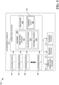
- the mapping vehicle 100 is configured to generate a three-dimensional map of a driving environment in which the mapping vehicle 100 operates.
- the mapping vehicle 100 traverses different portions of an operational region, the mapping vehicle 100 generates a three-dimensional map of the operational region.
- the three-dimensional map of the operational region includes data indicative of three-dimensional positions of surfaces of objects in the operational region.
- a three-dimensional map of an operational region that includes a building can include a plurality of points that are each indicative of a position of a point on an exterior surface of the building. Accordingly, the three-dimensional map is representative of positions of objects in the operational region.
- the mapping vehicle 100 includes a radar antenna array 102, a hardware logic component 104, and a computing system 106.
- the radar antenna array 102 can be an antenna array having any of various configurations.
- reference made herein to acts performed by a single radar antenna can also be performed by an array of antennas collectively controlled by way of electronic beamforming techniques.
- the antenna array 102 is configured to emit radar signals into the driving environment of the vehicle 100 and receive radar returns from objects in the driving environment.
- the hardware logic component 104 is configured to identify positions of object surfaces in the driving environment of the mapping vehicle 100 based upon the radar returns received by the antenna array 102.
- the computing system 106 is configured to update a three-dimensional map of an operational region of the vehicle 100 based upon the positions of object surfaces identified by the hardware logic component 104.
- the antenna array 102 receives radar returns from a driving environment of the mapping vehicle 100.
- the antenna array 102 can be configured as a frequency-modulated continuous wave (FMCW) radar array.
- FMCW frequency-modulated continuous wave
- the radar returns received by the antenna array 102 can be reflections of a radar signal output by one or more antennas of the antenna array 102 received from the driving environment.
- the mapping vehicle 100 can include a transmit antenna 105.
- the transmit antenna 105 can transmit a radar signal into the driving environment of the vehicle 100, and the antenna array 102 can receive reflections of the radar signal transmitted by the transmit antenna 105.
- the vehicle 100 can further include various additional componentry (not shown) that is configured for generating and processing a radar signal that is to be transmitted by way of the transmit antenna 105.
- the antenna array 102 outputs electrical signals that are indicative of the radar returns.
- the electrical signals output by the antenna array 102 are received by a signal processing component 107 that is configured to perform various analog signal processing operations over the electrical signals.
- the signal processing component 107 can include componentry configured to perform various signal processing operations such as filtering, signal conditioning, etc.
- the processed signals output by the signal processing component 107 are received by an ADC bank 108 that is included on the vehicle 100.
- the ADC bank 108 is configured to digitally sample the electrical signals output by the antenna array 102 and to output radar data that is indicative of the radar returns received by the antenna array 102.
- the hardware logic component 104 receives the radar data from the ADC bank 108.
- the ADC bank 108 can be included as a component of the hardware logic component 104.
- the hardware logic component includes a radar analysis component 110 that computes positions of points on surfaces of objects in the driving environment of the vehicle 100 based upon the radar data output by the ADC bank 108.
- the antenna array 102 is configured to emit the radar signals into the driving environment of the vehicle 100 as the vehicle 100 is traveling through the driving environment.
- Fig. 2 an exemplary driving environment 200 of the vehicle 100 is shown.
- the driving environment 200 includes the vehicle 100 and a roadway 202 on which the vehicle 100 travels.
- the driving environment 200 further includes a building 204, a hydrant 206, and a pedestrian 208 that are to one side of the roadway 202.
- the vehicle 100 travels along the roadway 202 in a forward direction 210.
- the antenna array 102 emits a radar signal 212 into the driving environment 200 at an angle offset from the forward direction 210 of motion of the vehicle 100.
- the antenna array 102 is positioned such that the radar signal 212 is emitted in a field-of-view FOV centered about a direction 214 that is orthogonal to the forward direction 210 of motion of the vehicle 100.
- the FOV of the antenna array 102 can be centered about a direction that is not orthogonal to the forward direction 210 of motion of the vehicle 100.
- the radar antenna 102 receives returns of the emitted radar signal 212 from the various objects in the driving environment 200 (e.g., the hydrant 206 and the building 204).
- the radar analysis component 110 is configured to determine three-dimensional coordinates of points on surfaces of the various objects in the driving environment 200 based upon the radar returns received by the antenna array 102. For example, the radar analysis component 110 can determine three-dimensional coordinates of a point 216 on a surface of the hydrant 206 based upon a return of the radar signal 212 received by the antenna array 102.
- Various exemplary aspects will be described below with reference to the point 216. However, it is to be understood that these aspects are applicable to substantially any point in a driving environment of the vehicle 100.
- the radar analysis component 110 can determine a range to the point 216 based upon the radar return from the point 216.
- the radar analysis component 110 can determine the range to the point 216 based upon a frequency difference between a reference signal (e.g., which can be a stored copy of the transmitted radar signal 212) and the received radar return.
- the radar analysis component 110 can determine the range to the point 216 based upon a time delay between transmission of the radar signal 212 (e.g., a pulsed radar signal) and receipt of the radar return at the antenna array 102.
- the radar analysis component 110 can determine an azimuth angle ⁇ to the point 216, measured relative to the direction 214 about which the FOV of the antenna array 102 is centered, based upon the radar return and the velocity of the vehicle 100 in the forward direction 210 by employing the SAR principle.
- the radar analysis component 110 can determine v radial based upon the radar return received by the antenna array 102.
- the forward velocity of the vehicle 100 can be determined based upon output of a vehicle motion sensor 112 mounted on the vehicle 100.
- the vehicle motion sensor 112 can be any of various sensors that output data indicative of a velocity of the vehicle 100, or output data from which the velocity of the vehicle 100 can be determined.
- the vehicle motion sensor 112 can be or include a speedometer.
- the vehicle motion sensor 112 can be or include an odometer or a GPS sensor.
- the hardware logic component 104 can be configured to compute a velocity of the vehicle 100 based upon traveled distance of the vehicle 100 (e.g., output by the odometer) or a series of positions of the vehicle 100 (e.g., output by the GPS sensor).
- the radar analysis component 110 can determine the azimuth angle ⁇ to a higher degree of precision than is typically achieved by conventional automotive radar systems. For example, the radar analysis component 110 can determine the azimuth angle ⁇ to a precision of less than or equal to 0.5°, less than or equal to 0.75°, or less than or equal to 1°.
- the vehicle 100 can be controlled to travel at a speed of at least 5 miles per hour, at least 10 miles per hour, or at least 20 miles per hour in the forward direction 210 during transmission of the radar signal 212 and receipt of its returns from the driving environment 200.
- the radar analysis component 110 can determine an elevation angle to the point 216 by employing AOA techniques between radar returns received at different antennas of the antenna array 102.
- Fig. 3 an exemplary radar antenna array 300 is shown.
- the radar antenna array 300 can be or be included in the antenna array 102.
- the antenna array 300 includes a plurality of n antennas 302 that are vertically aligned, where n is an integer greater than 1.
- the plurality of antennas 302 can include 8 or more antennas, 16 or more antennas, or 32 or more antennas.
- the antenna array 300 includes a first antenna 304 and a second antenna 306 wherein the antennas 304, 306 are vertically aligned but positioned at different heights.
- a number of the antennas 302 can be selected to provide a desired FOV in the elevation direction.
- the number of the antennas 302 can be selected such that the FOV in the elevation direction is greater than or equal to 30°, greater than or equal to 45°, or greater than or equal to 60°.
- the radar analysis component 110 can be configured to determine an elevation angle of the point 216 with respect to the antenna array 102 based upon TDOA between a first antenna in the array 102 and a second antenna in the array 102 that is positioned at a different height than the first antenna.
- the radar analysis component 110 can compute a TDOA of a return from the point 216 between the first antenna and the second antenna based upon the radar data associated with each of the first antenna and the second antenna.
- the radar analysis component 110 can then compute an elevation angle of the point based upon the computed TDOA.
- the range, azimuth angle, and elevation angle of the point 216 computed by the radar analysis component 110 define three-dimensional coordinates of the point 216.
- the radar analysis component 110 can output these coordinates to the computing system 106.
- the computing system 106 includes a processor 114, memory 116, and a data store 118.
- the data store 118 stores mapping data 119 that include a plurality of points that are representative of positions of surfaces of objects in an operational region of the mapping vehicle 100. Collectively, these mapping data 119 define a three-dimensional map of the operating region of the vehicle 100.
- the memory 116 stores instructions that are executed by the processor 114.
- the memory 116 includes a mapping component 120 that is configured to generate and/or update the mapping data 119 based upon data received from the radar analysis component 110.
- the mapping component 120 is configured to receive three-dimensional coordinates of a point in the driving environment as identified by the radar analysis component 110 (e.g., as described above).
- the mapping component 120 is configured to update the mapping data 119 to include the point. Prior to updating the mapping data 119 to include the point, the mapping component 120 can execute a transform to transform the range, azimuth, and elevation coordinates of the point to a different coordinate system such as, but not limited to, [latitude, longitude, height above ground]. Hence, as the mapping vehicle traverses the operational region and the radar analysis component 110 identifies additional points in the operational region based upon radar returns received by the antenna array 102, the mapping component 120 updates the mapping data 119 with points representative of positions of objects in the operational region.
- the vehicle 100 may be desirable for the vehicle 100 to exclude moving objects that are detected by the radar analysis component 110 from the mapping data 119.
- Moving objects such as vehicles, pedestrians, bicyclists, etc., tend to be ephemeral and may not be present at the same location in the operational region at different times.
- a static object such as a building is generally expected to be present at the same location over a long period of time (e.g., days, months, or years).
- the radar analysis component 110 can distinguish between static objects and moving objects by comparing an azimuth angle ⁇ for a point computed based upon the SAR principle (e.g., based upon Eq. 1) to an azimuth angle ⁇ for the same point computed based upon AOA techniques.
- the azimuth angle of a point on a moving object is not accurately computed by Eq. 1.
- the point can be inferred to represent a moving target.
- the radar analysis component 110 can be configured to compute, for a point in the driving environment, an azimuth angle ⁇ 1 based upon the SAR principle, and an azimuth angle ⁇ 2 based upon AOA techniques. If ⁇ 1 is not consistent with ⁇ 2 , the radar analysis component 110 can exclude the point in question from inclusion in the mapping data 119, on the inference that the point is representative of a moving target.
- the angles ⁇ 1 and ⁇ 2 are associated with some measure of uncertainty. For example, ⁇ 1 can be computed to a first value ⁇ 0.5° and ⁇ 2 can be computed to a second value ⁇ 3°.
- the radar analysis component 110 can identify a conflict between ⁇ 1 and ⁇ 2 when the uncertainty bounds of the angles ⁇ 1 and ⁇ 2 do not overlap. Responsive to identifying a conflict between ⁇ 1 and ⁇ 2 , the radar analysis component 110 can fail to output the associated point to the mapping component 120, and the point is not added to the mapping data 119.
- the antenna array 102 can include antennas that are horizontally offset from one another.
- the array 300 can include an additional antenna 308 that is offset from the vertically-aligned plurality of antennas 302.
- the additional antenna 308 can be horizontally aligned with one of the plurality of antennas 302 (e.g., the antenna 306 as shown in Fig. 3 ). Due to the horizontal offset of the additional antenna 308 from the plurality of antennas 302, an azimuth angle of a point can be determined using AOA techniques based upon radar returns of the additional antenna 308 and its horizontally aligned antenna 306.
- the array 400 is a two-dimensional array that includes a plurality of antennas arranged in l rows by m columns, where / and m are positive integers.
- the array 400 can include a first column of vertically aligned antennas 402 and a second column of vertically aligned antennas 404 that are horizontally offset from the first column of vertically aligned antennas 402.
- the radar analysis component 110 can compute an azimuth angle of a point using AOA techniques based upon radar returns of an antenna selected from the first column 402 and a corresponding horizontally aligned antenna from the second column 404.
- the mapping data 119 can be employed by an AV in connection with the AV navigating through its driving environment in the operational region represented by the mapping data 119.
- a first sensor system 502 through an Nth sensor system 508 The sensor systems 502-508 may be of different types.
- the first sensor system 502 may be a radar sensor system
- the second sensor system 504 may be a lidar sensor system
- the third sensor system 506 may be a camera (image) system
- the Nth sensor system 508 may be a sonar system.
- the various sensor systems 502-508 are arranged about the AV 500.
- the sensor systems 502-508 are configured to repeatedly (e.g. continuously, or periodically) output sensor data that is representative of objects and conditions in the driving environment of the AV 500.
- the AV 500 further includes several mechanical systems that are used to effectuate appropriate motion of the AV 500.
- the mechanical systems can include but are not limited to, a vehicle propulsion system 510, a braking system 512, and a steering system 514.
- the vehicle propulsion system 510 may be an electric engine, an internal combustion engine, or a combination thereof.
- the braking system 512 can include an engine brake, brake pads, actuators, a regenerative braking system, and/or any other suitable componentry that is configured to assist in decelerating the AV 500.
- the steering system 514 includes suitable componentry that is configured to control the direction of movement of the AV 500.
- the AV 500 additionally comprises a computing system 516 that is in communication with the sensor systems 502-508 and is further in communication with the vehicle propulsion system 510, the braking system 512, and the steering system 514.
- the computing system 516 includes a processor 518 and memory 520 that includes computer-executable instructions that are executed by the processor 518.
- the processor 518 can be or include a graphics processing unit (GPU), a plurality of GPUs, a central processing unit (CPU), a plurality of CPUs, an application-specific integrated circuit (ASIC), a microcontroller, a programmable logic controller (PLC), a field programmable gate array (FPGA), or the like.
- the memory 520 comprises a perception system 522, a planning system 524, and a control system 526.
- the perception system 522 is configured to identify the presence of objects and/or characteristics of objects in the driving environment of the AV 500.
- the planning system 524 is configured to plan a route and/or a maneuver of the AV 500 based upon data pertaining to objects in the driving environment that are output by the perception system 522.
- the control system 526 is configured to control the mechanical systems 510-514 of the AV 500 to effectuate appropriate motion to cause the AV 500 to execute a maneuver planned by the planning system 524.
- the perception system 522 is configured to identify objects (in proximity to the AV 500) captured in sensor signals output by the sensor systems 502-508.
- the perception system 522 can be configured to identify the presence of an object in the driving environment of the AV 500 based upon images generated by a camera system included in the sensor systems 502-508.
- the perception system 522 can be configured to determine a range to an object in the driving environment of the AV 500, a three-dimensional position of the object, or a radar cross-section of the object, based upon radar returns received by a radar sensor included in the sensor systems 502-508.
- the AV 500 can further include a data store 528 that stores mapping data 530.
- the mapping data 530 can include the mapping data 119 generated by the mapping vehicle 100.
- the mapping data 530 can include a map of navigable roadways in an operational region of the AV 500.
- the perception system 522 of the AV 500 can be configured to employ the mapping data 530 in connection with identifying objects and/or their properties.
- the perception system 522 can be configured to identify an object in lidar data based upon a three-dimensional map of the driving environment included in the mapping data 530.
- the perception system 522 can determine that a potentially mobile object is likely present at that location.
- the planning system 524 and the control system 526 can then plan and execute a maneuver for the AV 500, respectively, wherein the maneuver is based upon the likely presence of the potentially mobile object.
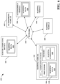
- an exemplary system 600 that facilitates aggregating mapping data from a fleet of mapping vehicles and disseminating the mapping data to a fleet of AVs.
- the system 600 includes the mapping vehicle 100 and a plurality of additional mapping vehicles 602, 604.
- the system 600 further includes a server computing device 606 that is in communication with the mapping vehicles 100, 602, 604 by way of a network 608.
- the system 600 still further includes the AV and one or more additional AVs 610 that are in communication with the server computing device 606 by way of the network 608.
- the server computing device 606 receives mapping data from each of the mapping vehicles 100, 602, 604 by way of the network 608.
- the mapping vehicle 100 generates the mapping data 119 as described above.
- the mapping vehicles 602, 604 can be configured to traverse different portions of an operational region of the mapping vehicles 100, 602, 604 than the mapping vehicle 100. Further, the mapping vehicles 602, 604 can be configured to generate mapping data pertaining to their respective driving environments based upon radar data, as described above with respect to the mapping vehicle 100. In other embodiments, one or more of the additional mapping vehicles can be configured to generate mapping data based upon lidar data generated by lidar sensors (not shown) mounted on board the mapping vehicles 602, 604.
- the server computing device 606 includes a data store 612 that stores mapping data 614 that pertains to an entire operational region of the mapping vehicles 100, 602, 604 and/or the AVs 500, 610.
- the server computing device 606 receives mapping data from each of the mapping vehicles 100, 602, 604, and updates the mapping data 614.
- the mapping data 614 is updated with new information.
- the mapping vehicles 100, 602, 604 can be configured to transmit updated mapping data to the server computing device 606 periodically as the vehicles 100, 602, 604 traverse their respective portions of the operational region.
- the mapping vehicles 100, 602, 604 can be configured to provide mapping data updates to the server computing device 606 in a single bulk update upon completion of a traversal of a portion of the operational region.
- the server computing device 606 is configured to transmit the mapping data 614 to the AVs 500, 610 for use by the AVs 500, 610 in navigating through the operational region represented by the mapping data 614. In some embodiments, the server computing device 606 can transmit the mapping data 614 to the AVs 500, 610 while the AVs 500, 610 are operating in the operational region. In other embodiments, the server computing device 606 can transmit the mapping data 614 to the AVs 500, 610 during down-time of the AVs 500, 610 (e.g., when the AVs 500, 610 are out of operation for maintenance or refueling).
- Fig. 7 illustrates an exemplary methodology 700 relating to generating mapping data pertaining to a driving environment of a vehicle based upon radar data by employing SAR principles. While the methodology is shown and described as being a series of acts that are performed in a sequence, it is to be understood and appreciated that the methodology is not limited by the order of the sequence. For example, some acts can occur in a different order than what is described herein. In addition, an act can occur concurrently with another act. Further, in some instances, not all acts may be required to implement the methodology described herein.
- the acts described herein may be computer-executable instructions that can be implemented by one or more processors and/or stored on a computer-readable medium or media.
- the computer-executable instructions can include a routine, a sub-routine, programs, a thread of execution, and/or the like.
- results of acts of the methodologies can be stored in a computer-readable medium, displayed on a display device, and/or the like.
- the methodology 700 starts at 702, and at 704 a first radar return is received from a first antenna mounted on a vehicle.
- the first vehicle-mounted antenna can be included in an array of antennas.
- a second radar return is received from a second antenna mounted on the vehicle.
- the second vehicle-mounted antenna can be included in a same array of antennas as the first vehicle-mounted antenna.
- data indicative of a velocity of the vehicle is received. For example, odometer data indicative of a distance traveled by the vehicle over a period of time can be received. In other embodiments, a velocity of the vehicle can be directly read out from a speedometer mounted on the vehicle.
- a position of a point on a surface in the driving environment of the vehicle is computed based upon the radar returns received by the first and second radar antennas at 704 and 706, respectively, and the velocity of the vehicle received at 708.
- a radial velocity of the point relative to the first radar antenna can be computed based upon the first radar return.
- n azimuth angle of the point can be determined based upon the radial velocity and the velocity of the vehicle.
- an elevation angle of the point can be determined based upon the first radar return and the second radar return by employing AOA techniques.
- a range from the first radar antenna to the point can be determined based upon the first radar return. In a non-limiting example, the range can be determined based upon a frequency difference between the first radar return and a reference signal (e.g., in embodiments wherein the radar antennas are configured for FMCW operation).
- a three-dimensional map of the driving environment of the vehicle is updated to indicate that an object is present at the position of the point computed at 710.
- the methodology 700 ends at 714.
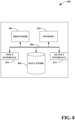
- the computing device 800 may be or include the computing systems 106 or 516.
- the computing device 800 includes at least one processor 802 that executes instructions that are stored in a memory 804.
- the instructions may be, for instance, instructions for implementing functionality described as being carried out by one or more modules, components, or systems discussed above or instructions for implementing one or more of the methods described above.
- the processor 802 may be a GPU, a plurality of GPUs, a CPU, a plurality of CPUs, a multi-core processor, etc.
- the processor 802 may access the memory 804 by way of a system bus 806.
- the memory 804 may also store radar data, velocity data, etc.
- the computing device 800 additionally includes a data store 808 that is accessible by the processor 802 by way of the system bus 806.
- the data store 808 may include executable instructions, sensor data, radar data, velocity data, mapping data, etc.
- the computing device 800 also includes an input interface 810 that allows external devices to communicate with the computing device 800. For instance, the input interface 810 may be used to receive instructions from an external computing device, etc.
- the computing device 800 also includes an output interface 812 that interfaces the computing device 800 with one or more external devices. For example, the computing device 800 may transmit control signals to the vehicle propulsion system 510, the braking system 512, and/or the steering system 514 by way of the output interface 812.
- the computing device 800 may be a distributed system. Thus, for instance, several devices may be in communication by way of a network connection and may collectively perform tasks described as being performed by the computing device 800.
- Computer-readable media includes computer-readable storage media.
- a computer-readable storage media can be any available storage media that can be accessed by a computer.
- such computer-readable storage media can comprise RAM, ROM, EEPROM, CD-ROM or other optical disk storage, magnetic disk storage or other magnetic storage devices, or any other medium that can be used to store desired program code in the form of instructions or data structures and that can be accessed by a computer.
- Disk and disc include compact disc (CD), laser disc, optical disc, digital versatile disc (DVD), floppy disk, and Blu-ray disc (BD), where disks usually reproduce data magnetically and discs usually reproduce data optically with lasers. Further, a propagated signal is not included within the scope of computer-readable storage media.
- Computer-readable media also includes communication media including any medium that facilitates transfer of a computer program from one place to another. A connection, for instance, can be a communication medium.
- the software is transmitted from a website, server, or other remote source using a coaxial cable, fiber optic cable, twisted pair, digital subscriber line (DSL), or wireless technologies such as infrared, radio, and microwave
- coaxial cable, fiber optic cable, twisted pair, DSL, or wireless technologies such as infrared, radio and microwave
- the coaxial cable, fiber optic cable, twisted pair, DSL, or wireless technologies such as infrared, radio and microwave
- the functionally described herein can be performed, at least in part, by one or more hardware logic components.
- illustrative types of hardware logic components include FPGAs, ASICs, Application-specific Standard Products (ASSPs), System-on-a-chip systems (SOCs), Complex Programmable Logic Devices (CPLDs), etc.
- the features described herein relate to systems and methods for generating a three-dimensional map of a region based upon output of a radar sensor, and operating an AV within the region based upon the three-dimensional map according to at least the examples provided below:
Landscapes
- Engineering & Computer Science (AREA)
- Remote Sensing (AREA)
- Radar, Positioning & Navigation (AREA)
- Physics & Mathematics (AREA)
- Computer Networks & Wireless Communication (AREA)
- General Physics & Mathematics (AREA)
- Electromagnetism (AREA)
- Radar Systems Or Details Thereof (AREA)
- Signal Processing (AREA)
Priority Applications (2)
| Application Number | Priority Date | Filing Date | Title |
|---|---|---|---|
| EP21206687.2A EP4177635A1 (de) | 2021-11-05 | 2021-11-05 | Autoradar zur abbildung und lokalisierung |
| US17/520,581 US12222418B2 (en) | 2021-11-05 | 2021-11-05 | Automotive radar for mapping and localization |
Applications Claiming Priority (1)
| Application Number | Priority Date | Filing Date | Title |
|---|---|---|---|
| EP21206687.2A EP4177635A1 (de) | 2021-11-05 | 2021-11-05 | Autoradar zur abbildung und lokalisierung |
Publications (1)
| Publication Number | Publication Date |
|---|---|
| EP4177635A1 true EP4177635A1 (de) | 2023-05-10 |
Family
ID=78536037
Family Applications (1)
| Application Number | Title | Priority Date | Filing Date |
|---|---|---|---|
| EP21206687.2A Pending EP4177635A1 (de) | 2021-11-05 | 2021-11-05 | Autoradar zur abbildung und lokalisierung |
Country Status (2)
| Country | Link |
|---|---|
| US (1) | US12222418B2 (de) |
| EP (1) | EP4177635A1 (de) |
Cited By (1)
| Publication number | Priority date | Publication date | Assignee | Title |
|---|---|---|---|---|
| US12222418B2 (en) | 2021-11-05 | 2025-02-11 | Gm Cruise Holdings Llc | Automotive radar for mapping and localization |
Citations (5)
| Publication number | Priority date | Publication date | Assignee | Title |
|---|---|---|---|---|
| WO2004059341A1 (de) * | 2002-12-20 | 2004-07-15 | Daimlerchrysler Ag | Verfahren zum erfassen von umgebungsinformationen und zum bestimmen der lage einer parklücke |
| US20120169532A1 (en) * | 2009-09-25 | 2012-07-05 | Toyota Jidosha Kabushiki Kaisha | Vehicle-mounted radar device |
| DE102017123902A1 (de) * | 2017-10-13 | 2019-04-18 | Conti Temic Microelectronic Gmbh | Verfahren zur Schätzung von Lagedaten basierend auf Radarinformationen |
| US20200174115A1 (en) * | 2018-05-18 | 2020-06-04 | Zendar Inc. | Systems and methods for detecting objects |
| US20210215817A1 (en) * | 2018-08-17 | 2021-07-15 | Aura Intelligent Systems, Inc. | Synthetic aperture antenna array for 3d imaging |
Family Cites Families (4)
| Publication number | Priority date | Publication date | Assignee | Title |
|---|---|---|---|---|
| WO2020072041A1 (en) * | 2018-10-02 | 2020-04-09 | Oculii Corp. | Systems and methods for stereo radar tracking |
| WO2021014686A1 (ja) * | 2019-07-24 | 2021-01-28 | ソニー株式会社 | レーダー装置、処理装置、算出方法、及び算出プログラム |
| US11209524B2 (en) * | 2019-09-30 | 2021-12-28 | Veoneer Us, Inc. | Detection system and method for characterizing targets |
| EP4177635A1 (de) | 2021-11-05 | 2023-05-10 | GM Cruise Holdings LLC | Autoradar zur abbildung und lokalisierung |
-
2021
- 2021-11-05 EP EP21206687.2A patent/EP4177635A1/de active Pending
- 2021-11-05 US US17/520,581 patent/US12222418B2/en active Active
Patent Citations (5)
| Publication number | Priority date | Publication date | Assignee | Title |
|---|---|---|---|---|
| WO2004059341A1 (de) * | 2002-12-20 | 2004-07-15 | Daimlerchrysler Ag | Verfahren zum erfassen von umgebungsinformationen und zum bestimmen der lage einer parklücke |
| US20120169532A1 (en) * | 2009-09-25 | 2012-07-05 | Toyota Jidosha Kabushiki Kaisha | Vehicle-mounted radar device |
| DE102017123902A1 (de) * | 2017-10-13 | 2019-04-18 | Conti Temic Microelectronic Gmbh | Verfahren zur Schätzung von Lagedaten basierend auf Radarinformationen |
| US20200174115A1 (en) * | 2018-05-18 | 2020-06-04 | Zendar Inc. | Systems and methods for detecting objects |
| US20210215817A1 (en) * | 2018-08-17 | 2021-07-15 | Aura Intelligent Systems, Inc. | Synthetic aperture antenna array for 3d imaging |
Cited By (1)
| Publication number | Priority date | Publication date | Assignee | Title |
|---|---|---|---|---|
| US12222418B2 (en) | 2021-11-05 | 2025-02-11 | Gm Cruise Holdings Llc | Automotive radar for mapping and localization |
Also Published As
| Publication number | Publication date |
|---|---|
| US20230145703A1 (en) | 2023-05-11 |
| US12222418B2 (en) | 2025-02-11 |
Similar Documents
| Publication | Publication Date | Title |
|---|---|---|
| JP7506829B2 (ja) | 自律車両用途のための速度推定および物体追跡 | |
| US11353589B2 (en) | Iterative closest point process based on lidar with integrated motion estimation for high definition maps | |
| US11702102B2 (en) | Filtering return points in a point cloud based on radial velocity measurement | |
| US12061276B2 (en) | Perception data based GNSS multipath identification and correction | |
| US10705220B2 (en) | System and method for ground and free-space detection | |
| US20230085887A1 (en) | Systems and methods for high velocity resolution high update rate radar for autonomous vehicles | |
| US20190324471A1 (en) | System and method for ground plane detection | |
| US20230384441A1 (en) | Estimating three-dimensional target heading using a single snapshot | |
| JP2025065215A (ja) | 地図作成装置、制御方法、プログラム及び記憶媒体 | |
| US12066542B2 (en) | Lidar system that generates a point cloud having multiple resolutions | |
| CN110660218B (zh) | 利用毫米波雷达的高精度地图制作方法及系统 | |
| US12523758B2 (en) | Systems and methods for online calibration in distributed aperture radar | |
| CN115166791A (zh) | 一种智能驾驶车辆双gnss天线航向角标定方法及装置 | |
| US11175382B2 (en) | Elevation angle estimation in horizontal antenna array with doppler and velocity measurements | |
| EP4148388B1 (de) | Fahrzeuglokalisierung auf basis von kartendaten | |
| US20200278688A1 (en) | Method for autonomous parking of a vehicle, and an autonomous vehicle thereof | |
| JP7808722B2 (ja) | 情報処理装置、地図データ生成装置、方法及びプログラム | |
| CN116890847A (zh) | 车辆姿势评估 | |
| US20230184890A1 (en) | Intensity-based lidar-radar target | |
| US12222418B2 (en) | Automotive radar for mapping and localization | |
| CN113767376B (zh) | 用于在车辆部件之间传送信息的消息缓存器 | |
| EP4174517A1 (de) | Domänenanpassung von sensordaten eines autonomen fahrzeugs | |
| US20250110212A1 (en) | Radar free space mapping | |
| US12546860B2 (en) | Magnitude calibration of radar sensor based on radar map of known objects | |
| EP4517378A1 (de) | Linearer kalmanfilter mit radar 2d vektor geschwindigkeit objektschätzung mittels verteiltem radar netzwerk |
Legal Events
| Date | Code | Title | Description |
|---|---|---|---|
| PUAI | Public reference made under article 153(3) epc to a published international application that has entered the european phase |
Free format text: ORIGINAL CODE: 0009012 |
|
| STAA | Information on the status of an ep patent application or granted ep patent |
Free format text: STATUS: THE APPLICATION HAS BEEN PUBLISHED |
|
| AK | Designated contracting states |
Kind code of ref document: A1 Designated state(s): AL AT BE BG CH CY CZ DE DK EE ES FI FR GB GR HR HU IE IS IT LI LT LU LV MC MK MT NL NO PL PT RO RS SE SI SK SM TR |
|
| P01 | Opt-out of the competence of the unified patent court (upc) registered |
Effective date: 20230526 |
|
| STAA | Information on the status of an ep patent application or granted ep patent |
Free format text: STATUS: REQUEST FOR EXAMINATION WAS MADE |
|
| 17P | Request for examination filed |
Effective date: 20231110 |
|
| RBV | Designated contracting states (corrected) |
Designated state(s): AL AT BE BG CH CY CZ DE DK EE ES FI FR GB GR HR HU IE IS IT LI LT LU LV MC MK MT NL NO PL PT RO RS SE SI SK SM TR |
|
| STAA | Information on the status of an ep patent application or granted ep patent |
Free format text: STATUS: EXAMINATION IS IN PROGRESS |
|
| 17Q | First examination report despatched |
Effective date: 20251128 |