EP4177520B1 - Safe start-up of a cooled radiant tube burner at high temperature operation - Google Patents
Safe start-up of a cooled radiant tube burner at high temperature operation Download PDFInfo
- Publication number
- EP4177520B1 EP4177520B1 EP22202500.9A EP22202500A EP4177520B1 EP 4177520 B1 EP4177520 B1 EP 4177520B1 EP 22202500 A EP22202500 A EP 22202500A EP 4177520 B1 EP4177520 B1 EP 4177520B1
- Authority
- EP
- European Patent Office
- Prior art keywords
- burner
- temperature
- furnace
- radiant tube
- radiant
- Prior art date
- Legal status (The legal status is an assumption and is not a legal conclusion. Google has not performed a legal analysis and makes no representation as to the accuracy of the status listed.)
- Active
Links
Images

Classifications
-
- F—MECHANICAL ENGINEERING; LIGHTING; HEATING; WEAPONS; BLASTING
- F23—COMBUSTION APPARATUS; COMBUSTION PROCESSES
- F23N—REGULATING OR CONTROLLING COMBUSTION
- F23N5/00—Systems for controlling combustion
- F23N5/02—Systems for controlling combustion using devices responsive to thermal changes or to thermal expansion of a medium
- F23N5/022—Systems for controlling combustion using devices responsive to thermal changes or to thermal expansion of a medium using electronic means
-
- F—MECHANICAL ENGINEERING; LIGHTING; HEATING; WEAPONS; BLASTING
- F23—COMBUSTION APPARATUS; COMBUSTION PROCESSES
- F23N—REGULATING OR CONTROLLING COMBUSTION
- F23N5/00—Systems for controlling combustion
- F23N5/24—Preventing development of abnormal or undesired conditions, i.e. safety arrangements
- F23N5/245—Preventing development of abnormal or undesired conditions, i.e. safety arrangements using electrical or electromechanical means
-
- F—MECHANICAL ENGINEERING; LIGHTING; HEATING; WEAPONS; BLASTING
- F23—COMBUSTION APPARATUS; COMBUSTION PROCESSES
- F23C—METHODS OR APPARATUS FOR COMBUSTION USING FLUID FUEL OR SOLID FUEL SUSPENDED IN A CARRIER GAS OR AIR
- F23C3/00—Combustion apparatus characterised by the shape of the combustion chamber
- F23C3/002—Combustion apparatus characterised by the shape of the combustion chamber the chamber having an elongated tubular form, e.g. for a radiant tube
-
- F—MECHANICAL ENGINEERING; LIGHTING; HEATING; WEAPONS; BLASTING
- F23—COMBUSTION APPARATUS; COMBUSTION PROCESSES
- F23C—METHODS OR APPARATUS FOR COMBUSTION USING FLUID FUEL OR SOLID FUEL SUSPENDED IN A CARRIER GAS OR AIR
- F23C2900/00—Special features of, or arrangements for combustion apparatus using fluid fuels or solid fuels suspended in air; Combustion processes therefor
- F23C2900/99001—Cold flame combustion or flameless oxidation processes
-
- F—MECHANICAL ENGINEERING; LIGHTING; HEATING; WEAPONS; BLASTING
- F23—COMBUSTION APPARATUS; COMBUSTION PROCESSES
- F23N—REGULATING OR CONTROLLING COMBUSTION
- F23N2225/00—Measuring
- F23N2225/08—Measuring temperature
- F23N2225/16—Measuring temperature burner temperature
-
- F—MECHANICAL ENGINEERING; LIGHTING; HEATING; WEAPONS; BLASTING
- F23—COMBUSTION APPARATUS; COMBUSTION PROCESSES
- F23N—REGULATING OR CONTROLLING COMBUSTION
- F23N2227/00—Ignition or checking
- F23N2227/02—Starting or ignition cycles
-
- F—MECHANICAL ENGINEERING; LIGHTING; HEATING; WEAPONS; BLASTING
- F23—COMBUSTION APPARATUS; COMBUSTION PROCESSES
- F23N—REGULATING OR CONTROLLING COMBUSTION
- F23N2231/00—Fail safe
- F23N2231/12—Fail safe for ignition failures
-
- F—MECHANICAL ENGINEERING; LIGHTING; HEATING; WEAPONS; BLASTING
- F23—COMBUSTION APPARATUS; COMBUSTION PROCESSES
- F23N—REGULATING OR CONTROLLING COMBUSTION
- F23N2237/00—Controlling
- F23N2237/02—Controlling two or more burners
-
- Y—GENERAL TAGGING OF NEW TECHNOLOGICAL DEVELOPMENTS; GENERAL TAGGING OF CROSS-SECTIONAL TECHNOLOGIES SPANNING OVER SEVERAL SECTIONS OF THE IPC; TECHNICAL SUBJECTS COVERED BY FORMER USPC CROSS-REFERENCE ART COLLECTIONS [XRACs] AND DIGESTS
- Y02—TECHNOLOGIES OR APPLICATIONS FOR MITIGATION OR ADAPTATION AGAINST CLIMATE CHANGE
- Y02E—REDUCTION OF GREENHOUSE GAS [GHG] EMISSIONS, RELATED TO ENERGY GENERATION, TRANSMISSION OR DISTRIBUTION
- Y02E20/00—Combustion technologies with mitigation potential
- Y02E20/34—Indirect CO2mitigation, i.e. by acting on non CO2directly related matters of the process, e.g. pre-heating or heat recovery
Definitions
- the invention relates to a furnace heating device and a method for igniting burners designed for flameless oxidation in order to heat intermittently operated radiant tubes.
- EP 0 463 218 A1 discloses the operation of burners with flameless oxidation. This operation is based on injecting a fuel and pre-heated air at high speed into a waste gas recirculation eddy. A burner is used to heat the combustion chamber and is operated with a flame. Once the operating temperature has been reached, it is possible to switch over to flameless oxidation.
- DE 102 17 524 B4 discloses the heating of radiant tubes by means of burners which operate with flameless oxidation. Burners of this kind are also designed to assume an operating mode with flame in the heating phase.
- EP 1 995 515 B1 discloses a burner for heating furnace chambers by means of flameless oxidation, in which the operating temperature is below a limit temperature necessary for the flameless oxidation. To this end, hot gases are generated by means of a steadily burning flame and are used to assist and maintain the otherwise flameless oxidation.
- US20190120483A1 discloses a method of heating a furnace using radiant tubes with flameless operation below oven temperature of 850°C and flameless operation with furnace temperature monitoring by means of two safety temperature monitors for two temperature limits such as 770°C and 850°C. This method extends the temperature range for flameless operation to temperatures below 850°C such as above 770°C instead of only above 850°C.
- Radiant tubes are typically used for indirect heating of industrial furnaces for temperatures up to approximately 1200° C.
- the radiant tubes are heated from the inside, wherein the radiant tube can be heated by flameless oxidation, which significantly reduces the nitrogen oxides in the waste gas.
- the radiant tubes must be switched on and off whilst still warm from operation.
- the radiant tubes are heated by burners with a flame and if the process is performed with high air preheating (in particular preheating to more than 500° C) for energy conservation reasons, the resultant nitrogen oxide values are unacceptably high.
- the operation of the burners with flameless oxidation by contrast leads to lower nitrogen oxide values, wherein according to experience, in the case of furnaces heated by means of radiant tube, a furnace operating temperature of at least 850° C is necessary in order to be able to reliably put a burner into operation with flameless oxidation.
- furnace operating temperatures below 850° C can be considered critical for intermittent flameless burner operation (flameless pulsed burning).
- the furnace system switches from flame monitoring to temperature monitoring at a central position after the ignition temperature has been reached.
- the temperature monitoring must be carried out with an approved complex fail-safe double thermocouple.
- the central position is not the coolest position under all conditions. After a cooling mode, the temperature in each individual radiant tube can fall below the monitored furnace chamber temperature.
- a thermocouple would need to be integrated in each radiant tube to reliably monitor a temperature above a critical temperature.
- WO2020/253970A1 which discloses a burner for heating a heating space, with a reduction of NOx emissions.
- the burner comprises a mixing and combustion chamber, a mixing and igniting device that is arranged in the mixing and combustion chamber, and a fuel supply that is connected to the mixing and igniting device and is designed to supply fuel to the mixing and igniting device.
- an air supply is provided, which is designed to supply at least one partial airflow to the mixing and combustion chamber.
- a combustion chamber opening opens the mixing and combustion chamber toward a heating space to be heated.
- control means are designed to control a fuel flow via the fuel supply and to control at least one partial airflow via the air supply, the burner, and the control means is designed for the operation of the burner with a stable flame that extends from the mixing and igniting device into the heating space through the combustion chamber opening.
- a furnace heating device is provided for the heating a furnace chamber in accordance with claim 1.
- Another embodiment provides a method for controlling a furnace heating device in accordance with claim 5.
- the core of the present invention is that in the start-up in central temperature monitored flameless operation the flameless mode cannot be started until the combustion zone inside of a radiant tube is first brought above a critical temperature. This causes the combustion chamber temperature in the radiant tube to rise to a safe temperature above a critical temperature.
- the invention solves the safety problem described above by means of software in the fail-safe burner control. Having a temperature monitoring configuration for each individual radiant tube burner would be complex and the costs for a double thermocouple with fail-safe evaluation per burner would be prohibitive, especially with the number of burners found in a typical furnace. With this innovation there is a higher safety and at the same time a competitive advantage over existing systems.
- the cooling of the radiant tube interior below a critical temperature and below the furnace chamber temperature detected by the usual temperature monitoring at a central point can only be achieved by control processes, e.g. cooling or purging by the user.
- This control process is performed by a burner control unit.
- this burner control system memorizes the process. In the case of a previously used cooling process, the start-up must not follow a high-temperature start-up afterwards, as this can lead to an explosion.
- the temperature in the radiant tube must first be brought to a value above a critical temperature and only then may the start-up or switchover of the burner occur in high-temperature operation follow.
- the time needed to reach the required temperature in the radiant tube is given by the mechanical construction and can be defined depending on the size of the radiant tube and the burner capacity.
- the furnace operator can use the burners for cooling and heating according to his control without any risk.
- the determined time for reaching the critical temperature must be parameterized. Depending on the capacity of the burner and the radiant tube volume, the time to be determined for this system must be defined.
- the burner is started in high temperature mode. Flame operation is activated after cool down after one of the following conditions have occurred: The device was switched on, there was a purge of gases in the burner tubes or there was a cooling process. A start attempt or a restart of the burner does not cause this start-up in flame operation to be aborted. The start in flame operation is repeated until the required burning time for heating up the burner is reached.
- a typical furnace there may be 2-20 burners per zone. There may be one or two or as many as 10 zones within a furnace.
- the furnace heating device comprises at least one radiant tube, preferably a plurality of radiant tubes, which can be heated in each case by means of a burner (at least one burner), which in a first operating mode can be operated with flame and in a second operating mode can be operated without flame, i.e. with flameless oxidation.
- the interior of the radiant tube is preferably sealed off with respect to the furnace chamber.
- At least one control device is provided, by means of which the burner or the burners of the radiant tubes can be switched on and off and can be switched over between the first and the second operating mode.
- the temperature of the interior of the radiant tube in the case of an active burner is greater than the temperature of the furnace chamber.
- control device is designed to operate the burner temporarily in the first operating mode and then in the second operating mode in the event of a warm start. If the burner of the radiant tube is clocked, i.e., is operated with what is known as pulsed burning, the burner must be reliably started again and again.
- the furnace heating device can comprise a device for at least local detection of the furnace temperature, for example in the form of one or more switching temperature sensors. If a temperature sensor of this kind is arranged at a point of an industrial furnace, it determines the switching on and off of burners on the basis of the furnace temperature, but not on the basis of the radiant tube temperature.
- Fig. 1 shows three radiant tubes 5, 10 and 15 that are connected to burners 20, 25 and 30 that are connected with burner control units 50, 55 and 60.
- a sensor 40 is shown that sends data including temperature data to a control unit 45 that is configured to communicate through line 70 to each of burner control units 50, 55 and 60.
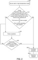
- FIG. 2 shows the steps involved in the operation of the process of the invention.
- box 500 is shown the start of the startup of the burner in high temperature mode. Before the gas is released for the flame, it is checked on a safety monitor as shown in box 510 if one of the following conditions was present before starting the burner:
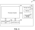
- FIG. 3 illustrates an example device 300 for detecting a safe point to start up according to the invention.
- the device 300 could, for example, denote any of the controllers, operator stations, or other devices in or used in conjunction with the system 100 in FIG. 1 .
- the device 300 could also represent the computing device that implements part or all of the control approach in FIG. 3 .
- the device 300 could be used in any other suitable system.
- the device 300 includes at least one processor system 302, at least one storage device 304, at least one communications unit 306, and at least one input/output (I/O) unit 308.
- processor system 302 can execute instructions, such as those that may be loaded into a memory 310. The instructions could implement the safe point functionality described herein.
- processor system 302 denotes any suitable processing device, such as one or more microprocessors, microcontrollers, digital signal processors, application specific integrated circuits (ASICs), field programmable gate arrays (FPGAs), or discrete circuitry.
- the memory 310 and a persistent storage 312 are examples of storage devices 304, which represent any structure(s) capable of storing and facilitating retrieval of information (such as data, program code, and/or other suitable information on a temporary or permanent basis).
- the memory 310 may represent a random-access memory or any other suitable volatile or non-volatile storage device(s).
- the persistent storage 312 may contain one or more components or devices supporting longer-term storage of data, such as a read only memory, hard drive, EEPROM, Flash memory, or optical disc.
- the communications unit 306 supports communications with other systems or devices.
- the communications unit 306 could include a network interface card or a wireless transceiver facilitating communications over a wired or wireless network.
- the communications unit 306 may support communications through any suitable physical or wireless communication link(s).
- the I/O unit 308 allows for input and output of data.
- the I/O unit 308 may provide a connection for user input through a keyboard, mouse, keypad, touchscreen, or other suitable input device.
- the I/O unit 308 may also send output to a display, printer, or other suitable output device.
- various functions described in this patent document are implemented or supported by a computer program that is formed from computer readable program code and that is embodied in a computer readable medium.
- computer readable program code includes any type of computer code, including source code, object code, and executable code.
- computer readable medium includes any type of medium capable of being accessed by a computer or controller, such as read only memory (ROM), random access memory (RAM), a hard disk drive, or any other type of memory.
- ROM read only memory
- RAM random access memory
- a "non-transitory” computer readable medium excludes wired, wireless, optical, or other communication links that transport transitory electrical or other signals.
- a non-transitory computer readable medium includes media where data can be permanently stored and media where data can be stored and later overwritten, such as a rewritable optical disc or an erasable storage device.
- application and “program” refer to one or more computer programs, software components, sets of instructions, procedures, functions, objects, classes, instances, related data, or a portion thereof adapted for implementation in a suitable computer code (including source code, object code, or executable code).
- program refers to one or more computer programs, software components, sets of instructions, procedures, functions, objects, classes, instances, related data, or a portion thereof adapted for implementation in a suitable computer code (including source code, object code, or executable code).
- communicate as well as derivatives thereof, encompasses both direct and indirect communication.
- the term “or” is inclusive, meaning and/or.
- phrases "associated with,” as well as derivatives thereof, may mean to include, be included within, interconnect with, contain, be contained within, connect to or with, couple to or with, be communicable with, cooperate with, interleave, juxtapose, be proximate to, be bound to or with, have, have a property of, have a relationship to or with, or the like.
- the phrase "at least one of,” when used with a list of items, means that different combinations of one or more of the listed items may be used, and only one item in the list may be needed. For example, "at least one of: A, B, and C" includes any of the following combinations: A, B, C, A and B, A and C, B and C, and A and B and C.
Landscapes
- Engineering & Computer Science (AREA)
- Chemical & Material Sciences (AREA)
- Combustion & Propulsion (AREA)
- Mechanical Engineering (AREA)
- General Engineering & Computer Science (AREA)
- Combustion Of Fluid Fuel (AREA)
Description
- The invention relates to a furnace heating device and a method for igniting burners designed for flameless oxidation in order to heat intermittently operated radiant tubes.
-
EP 0 463 218 A1 - Furthermore,
DE 102 17 524 B4 discloses the heating of radiant tubes by means of burners which operate with flameless oxidation. Burners of this kind are also designed to assume an operating mode with flame in the heating phase. -
EP 1 995 515 B1 discloses a burner for heating furnace chambers by means of flameless oxidation, in which the operating temperature is below a limit temperature necessary for the flameless oxidation. To this end, hot gases are generated by means of a steadily burning flame and are used to assist and maintain the otherwise flameless oxidation. -
US20190120483A1 discloses a method of heating a furnace using radiant tubes with flameless operation below oven temperature of 850°C and flameless operation with furnace temperature monitoring by means of two safety temperature monitors for two temperature limits such as 770°C and 850°C. This method extends the temperature range for flameless operation to temperatures below 850°C such as above 770°C instead of only above 850°C. - Radiant tubes are typically used for indirect heating of industrial furnaces for temperatures up to approximately 1200° C. In order to dissipate radiant heat, the radiant tubes are heated from the inside, wherein the radiant tube can be heated by flameless oxidation, which significantly reduces the nitrogen oxides in the waste gas.
- If the temperature of the industrial high temperature application is controlled by switching individual radiant tubes or entire radiant tube groups on and off, the radiant tubes must be switched on and off whilst still warm from operation. However, if the radiant tubes are heated by burners with a flame and if the process is performed with high air preheating (in particular preheating to more than 500° C) for energy conservation reasons, the resultant nitrogen oxide values are unacceptably high. The operation of the burners with flameless oxidation by contrast leads to lower nitrogen oxide values, wherein according to experience, in the case of furnaces heated by means of radiant tube, a furnace operating temperature of at least 850° C is necessary in order to be able to reliably put a burner into operation with flameless oxidation. If the furnace temperature is lower, however, deflagrations can occur in the event of intermittent operation, i.e. switching on and off of burners for output regulation. In this regard, furnace operating temperatures below 850° C can be considered critical for intermittent flameless burner operation (flameless pulsed burning).
- In high-temperature furnaces, which are gaining larger markets due to increasing low-emission requirements, the furnace system switches from flame monitoring to temperature monitoring at a central position after the ignition temperature has been reached. The temperature monitoring must be carried out with an approved complex fail-safe double thermocouple. In furnaces with indirect heating, i.e. the exhaust gases from the burners do not enter the furnace chamber, the central position is not the coolest position under all conditions. After a cooling mode, the temperature in each individual radiant tube can fall below the monitored furnace chamber temperature. As a consequence, a thermocouple would need to be integrated in each radiant tube to reliably monitor a temperature above a critical temperature.
- Examples of currently used systems can be found in the following documents:
-
US2019/120483A1 which discloses a device to heat a furnace chamber indirectly using radiant tubes, heating energy is transferred through the radiant tube wall into the furnace chamber. During steady-state operation, the temperature in the radiant tube and on its surface is higher than the furnace, depending on the specific heat output of the radiant tube. At a furnace temperature of 770° C. and a heat output of 50 kW/m2, the radiant tube has a temperature of 900° C. The radiant tube can thus operate continuously with flameless oxidation at this output, even though the temperature in the furnace is only 100° C. However, if the radiant tube has cooled to the furnace temperature of 770° C. during a break in burning, deflagration is avoided when the associated burner is ignited by initially operating said burner with a flame for a few seconds. -
US2013/157204A1 which discloses a method and apparatus for a burner adapted to heat a furnace or other environment of use. In particular, a burner for providing a fuel gas in combination with an oxidant to effect controlled reaction of the fuel gas in a manner to reduce NOx emissions is described. Combustion of the fuel gas is shifted from the burner combustor to a location outside the burner once the temperature within the furnace/radiant tube has reached a sufficient level to complete combustion of the fuel gas. -
WO2020/253970A1 which discloses a burner for heating a heating space, with a reduction of NOx emissions. The burner comprises a mixing and combustion chamber, a mixing and igniting device that is arranged in the mixing and combustion chamber, and a fuel supply that is connected to the mixing and igniting device and is designed to supply fuel to the mixing and igniting device. Furthermore, an air supply is provided, which is designed to supply at least one partial airflow to the mixing and combustion chamber. A combustion chamber opening opens the mixing and combustion chamber toward a heating space to be heated. In addition, control means are designed to control a fuel flow via the fuel supply and to control at least one partial airflow via the air supply, the burner, and the control means is designed for the operation of the burner with a stable flame that extends from the mixing and igniting device into the heating space through the combustion chamber opening. - A furnace heating device is provided for the heating a furnace chamber in accordance with claim 1.
- Another embodiment provides a method for controlling a furnace heating device in accordance with
claim 5. -
-
Fig. 1 shows a set of radiant tubes connected to burners with burner control units. -
Fig. 2 shows a flow scheme of the burner operation. -
Fig. 3 shows steps in the processing of data. - The core of the present invention is that in the start-up in central temperature monitored flameless operation the flameless mode cannot be started until the combustion zone inside of a radiant tube is first brought above a critical temperature. This causes the combustion chamber temperature in the radiant tube to rise to a safe temperature above a critical temperature. In comparison to the state of the art, the invention solves the safety problem described above by means of software in the fail-safe burner control. Having a temperature monitoring configuration for each individual radiant tube burner would be complex and the costs for a double thermocouple with fail-safe evaluation per burner would be prohibitive, especially with the number of burners found in a typical furnace. With this innovation there is a higher safety and at the same time a competitive advantage over existing systems. The cooling of the radiant tube interior below a critical temperature and below the furnace chamber temperature detected by the usual temperature monitoring at a central point can only be achieved by control processes, e.g. cooling or purging by the user. This control process is performed by a burner control unit. In accordance with the solution, this burner control system memorizes the process. In the case of a previously used cooling process, the start-up must not follow a high-temperature start-up afterwards, as this can lead to an explosion.
- In such a situation, the temperature in the radiant tube must first be brought to a value above a critical temperature and only then may the start-up or switchover of the burner occur in high-temperature operation follow. The time needed to reach the required temperature in the radiant tube is given by the mechanical construction and can be defined depending on the size of the radiant tube and the burner capacity.
- By using the burner control with the software extension, the furnace operator can use the burners for cooling and heating according to his control without any risk. In the burner control unit, the determined time for reaching the critical temperature must be parameterized. Depending on the capacity of the burner and the radiant tube volume, the time to be determined for this system must be defined.
- In a simplified operation of the burner control with the software extension, the burner is started in high temperature mode. Flame operation is activated after cool down after one of the following conditions have occurred: The device was switched on, there was a purge of gases in the burner tubes or there was a cooling process. A start attempt or a restart of the burner does not cause this start-up in flame operation to be aborted. The start in flame operation is repeated until the required burning time for heating up the burner is reached.
- In a typical furnace there may be 2-20 burners per zone. There may be one or two or as many as 10 zones within a furnace. In the operation of a radiant tube burner, it is desirable to control the burner without having a thermocouple on each burner tube. In starting up the burner, it is in flame mode and then switched to flameless mode. The flame continues to burn in the burner tube until the temperature is high enough so that flame monitoring may be turned off
- The furnace heating device according to the invention comprises at least one radiant tube, preferably a plurality of radiant tubes, which can be heated in each case by means of a burner (at least one burner), which in a first operating mode can be operated with flame and in a second operating mode can be operated without flame, i.e. with flameless oxidation. The interior of the radiant tube is preferably sealed off with respect to the furnace chamber. At least one control device is provided, by means of which the burner or the burners of the radiant tubes can be switched on and off and can be switched over between the first and the second operating mode. The temperature of the interior of the radiant tube in the case of an active burner is greater than the temperature of the furnace chamber. During breaks in operation, which occur repeatedly in the case of pulsed burning, the temperature in the interiors of the radiant tubes approaches the furnace temperature from above.
- In accordance with the invention the control device is designed to operate the burner temporarily in the first operating mode and then in the second operating mode in the event of a warm start. If the burner of the radiant tube is clocked, i.e., is operated with what is known as pulsed burning, the burner must be reliably started again and again.
- The furnace heating device can comprise a device for at least local detection of the furnace temperature, for example in the form of one or more switching temperature sensors. If a temperature sensor of this kind is arranged at a point of an industrial furnace, it determines the switching on and off of burners on the basis of the furnace temperature, but not on the basis of the radiant tube temperature.
-
Fig. 1 shows threeradiant tubes burners burner control units sensor 40 is shown that sends data including temperature data to acontrol unit 45 that is configured to communicate throughline 70 to each ofburner control units -
FIG. 2 shows the steps involved in the operation of the process of the invention. Atbox 500 is shown the start of the startup of the burner in high temperature mode. Before the gas is released for the flame, it is checked on a safety monitor as shown inbox 510 if one of the following conditions was present before starting the burner: - Device was switched off
- The burner has been purged
- The cooling operation was present
-
FIG. 3 illustrates anexample device 300 for detecting a safe point to start up according to the invention. Thedevice 300 could, for example, denote any of the controllers, operator stations, or other devices in or used in conjunction with the system 100 inFIG. 1 . Thedevice 300 could also represent the computing device that implements part or all of the control approach inFIG. 3 . However, thedevice 300 could be used in any other suitable system. - As shown in
FIG. 3 , thedevice 300 includes at least oneprocessor system 302, at least onestorage device 304, at least onecommunications unit 306, and at least one input/output (I/O)unit 308. Eachprocessor system 302 can execute instructions, such as those that may be loaded into amemory 310. The instructions could implement the safe point functionality described herein. Eachprocessor system 302 denotes any suitable processing device, such as one or more microprocessors, microcontrollers, digital signal processors, application specific integrated circuits (ASICs), field programmable gate arrays (FPGAs), or discrete circuitry. - The
memory 310 and apersistent storage 312 are examples ofstorage devices 304, which represent any structure(s) capable of storing and facilitating retrieval of information (such as data, program code, and/or other suitable information on a temporary or permanent basis). Thememory 310 may represent a random-access memory or any other suitable volatile or non-volatile storage device(s). Thepersistent storage 312 may contain one or more components or devices supporting longer-term storage of data, such as a read only memory, hard drive, EEPROM, Flash memory, or optical disc. - The
communications unit 306 supports communications with other systems or devices. For example, thecommunications unit 306 could include a network interface card or a wireless transceiver facilitating communications over a wired or wireless network. Thecommunications unit 306 may support communications through any suitable physical or wireless communication link(s).
The I/O unit 308 allows for input and output of data. For example, the I/O unit 308 may provide a connection for user input through a keyboard, mouse, keypad, touchscreen, or other suitable input device. The I/O unit 308 may also send output to a display, printer, or other suitable output device. - As explained above, after a cooling process, the burner must first be brought above the ignition temperature. The calculation of the time required to reheat the radiant heating tube can be done for either SI units or imperial units as explained in the following Example
- For SI units,
- T = required minimum heating time for reheating by flame in seconds
- D = diameter of the radiant tube in mm
- L = heated length of the radiant tube in mm
- P = gas connection capacity of the burner in kW
- T/s = 0,0037 x D/mm x L/mm / (P/kW)
- In an example where the radiant tube has D = 200 mm, L = 2000 mm, P = 40 kW

- For imperial units:
- T = required minimum heating time for reheating by flame in seconds
- D = diameter of the radiant tube in inch
- L = heated length of the radiant tube in inch
- P = gas connection capacity of the burner in BTU/hr

- Radiant tube with D = 7.9 inch, L = 78.7 inch, P = 151000 BTU/hr

- In some embodiments, various functions described in this patent document are implemented or supported by a computer program that is formed from computer readable program code and that is embodied in a computer readable medium. The phrase "computer readable program code" includes any type of computer code, including source code, object code, and executable code. The phrase "computer readable medium" includes any type of medium capable of being accessed by a computer or controller, such as read only memory (ROM), random access memory (RAM), a hard disk drive, or any other type of memory. A "non-transitory" computer readable medium excludes wired, wireless, optical, or other communication links that transport transitory electrical or other signals. A non-transitory computer readable medium includes media where data can be permanently stored and media where data can be stored and later overwritten, such as a rewritable optical disc or an erasable storage device.
- It may be advantageous to set forth definitions of certain words and phrases used throughout this patent document. The terms "application" and "program" refer to one or more computer programs, software components, sets of instructions, procedures, functions, objects, classes, instances, related data, or a portion thereof adapted for implementation in a suitable computer code (including source code, object code, or executable code). The term "communicate," as well as derivatives thereof, encompasses both direct and indirect communication. The terms "include" and "comprise," as well as derivatives thereof, mean inclusion without limitation. The term "or" is inclusive, meaning and/or. The phrase "associated with," as well as derivatives thereof, may mean to include, be included within, interconnect with, contain, be contained within, connect to or with, couple to or with, be communicable with, cooperate with, interleave, juxtapose, be proximate to, be bound to or with, have, have a property of, have a relationship to or with, or the like. The phrase "at least one of," when used with a list of items, means that different combinations of one or more of the listed items may be used, and only one item in the list may be needed. For example, "at least one of: A, B, and C" includes any of the following combinations: A, B, C, A and B, A and C, B and C, and A and B and C.
- The description in the present application should not be read as implying that any particular element, step, or function is an essential or critical element that must be included in the claim scope. The scope of patented subject matter is defined only by the allowed claims.
- While this invention has described certain embodiments and generally associated methods, alterations and permutations of these embodiments and methods will be apparent to those skilled in the art. Accordingly, the above description of example embodiments does not define or constrain this invention. Other changes, substitutions, and alterations are also possible without departing from the scope of this invention, as defined by the following claims
Claims (8)
- A furnace heating device, for heating a furnace chamber, comprising:at least one radiant tube (5) having a burner (20) and a combustion chamber, and configured to heat the furnace chamber, wherein said at least one radiant tube (5) is heated using said burner (20), wherein said burner (20) is operable in a first operating mode with a flame and in a second operating mode with flameless combustion, and wherein the temperature in the combustion chamber must be above a critical temperature for safe operation of flameless combustion;a burner control device (50) configured to control on and off states and operating mode setting for said burner (20) of said at least one radiant tube (5); andat least one single safety monitor for monitoring a temperature of said furnace chamber and communicating said temperature to said burner control device (50),wherein said burner control device (50) is configured to send a signal to prevent the start of said flameless combustion when it is determined that said temperature of the furnace chamber is above said critical temperature and a cooling process or a purging process or a control device switch on procedure has occurred.
- The furnace heating device of claim 1, wherein said burner control device (50) is further configured with information on sizes of radiant tubes (5, 10, 15) and burner capacity within said furnace chamber.
- The furnace heating device of claim 1 comprising a plurality of zones, wherein each zone includes said at least one single safety monitor.
- The furnace heating device of claim 3, wherein a group of radiant tubes (5, 10, 15) are monitored by said at least one single safety monitor.
- A method for controlling a furnace heating device comprising:a. determining factors for when a safe start-up of a furnace containing radiant tubes (5, 10, 15) heated by burners (20, 25, 30) takes place; andb. sending a signal to said furnace heating device from a burner control device (50) to prevent start of flameless combustion in said radiant tubes (5, 10, 15) when said factors indicate that a temperature within a furnace chamber is above a critical temperature for safe operation of flameless combustion and a cooling process or a purging process or a control device switch on procedure has occurred.
- The method of claim 5, wherein said factors comprise a measurement of time during which a smd- temperature within a radiant tube (5) is expected to be above said a critical temperature at which safe start-up with flameless mode of burners (20, 25, 30) of said furnace occurs.
- The method of claim 5, wherein said factors are determined based upon a volume of a radiant tube (5) and a capacity of a burner (20).
- The method of claim 5, wherein said factors comprise a minimum heating time, for each of said radiant tubes (5, 10, 15), for reheating by flame, and wherein the minimum heating time for each of said radiant tubes (5, 10, 15) is determined based on a diameter of a respective radiant tube, a heated length of a respective radiant tube, and a gas connection capacity of a burner (20).
Applications Claiming Priority (1)
| Application Number | Priority Date | Filing Date | Title |
|---|---|---|---|
| US17/521,441 US12398885B2 (en) | 2021-11-08 | 2021-11-08 | Safe start-up of a cooled radiant tube burner at high temperature operation |
Publications (2)
| Publication Number | Publication Date |
|---|---|
| EP4177520A1 EP4177520A1 (en) | 2023-05-10 |
| EP4177520B1 true EP4177520B1 (en) | 2025-01-29 |
Family
ID=83899673
Family Applications (1)
| Application Number | Title | Priority Date | Filing Date |
|---|---|---|---|
| EP22202500.9A Active EP4177520B1 (en) | 2021-11-08 | 2022-10-19 | Safe start-up of a cooled radiant tube burner at high temperature operation |
Country Status (2)
| Country | Link |
|---|---|
| US (1) | US12398885B2 (en) |
| EP (1) | EP4177520B1 (en) |
Families Citing this family (1)
| Publication number | Priority date | Publication date | Assignee | Title |
|---|---|---|---|---|
| US20260055892A1 (en) | 2024-08-21 | 2026-02-26 | Honeywell International Inc. | Optimized furnace burner adjustment for flameless combustion |
Family Cites Families (11)
| Publication number | Priority date | Publication date | Assignee | Title |
|---|---|---|---|---|
| DE59007772D1 (en) | 1990-06-29 | 1995-01-05 | Wuenning Joachim | Method and device for burning fuel in a combustion chamber. |
| DE10217524B4 (en) | 2002-04-19 | 2005-10-13 | WS - Wärmeprozesstechnik GmbH | Burner with side outlet for flameless oxidation |
| EP1995515B1 (en) | 2007-05-23 | 2013-10-30 | WS-Wärmeprozesstechnik GmbH | Supported FLOX operation and burner therefor |
| WO2013096646A1 (en) | 2011-12-20 | 2013-06-27 | Eclipse, Inc. | METHOD AND APPARATUS FOR A DUAL MODE BURNER YIELDING LOW NOx EMISSION |
| WO2013152012A1 (en) * | 2012-04-03 | 2013-10-10 | Eclipse, Inc. | METHOD AND APPARATUS FOR A DUAL MODE BURNER YIELDING LOW NOx EMISSION |
| US10422531B2 (en) | 2012-09-15 | 2019-09-24 | Honeywell International Inc. | System and approach for controlling a combustion chamber |
| EP3242080B1 (en) | 2016-05-04 | 2019-07-10 | WS-Wärmeprozesstechnik GmbH | Apparatus and method for heating of furnaces using radiant tubes |
| DE102016111656A1 (en) * | 2016-06-24 | 2017-12-28 | WS - Wärmeprozesstechnik GmbH | Burner with open jet |
| US10378765B2 (en) | 2017-04-24 | 2019-08-13 | Honeywell International Inc. | Apparatus and method for detecting furnace flooding |
| JP7218186B2 (en) * | 2019-01-16 | 2023-02-06 | 東京瓦斯株式会社 | How to provide diagnostic information for combustion equipment |
| MX2021006327A (en) | 2019-06-21 | 2021-08-11 | Econova GmbH | Burner for reducing nox emissions and method for operating the burner. |
-
2021
- 2021-11-08 US US17/521,441 patent/US12398885B2/en active Active
-
2022
- 2022-10-19 EP EP22202500.9A patent/EP4177520B1/en active Active
Also Published As
| Publication number | Publication date |
|---|---|
| EP4177520A1 (en) | 2023-05-10 |
| US12398885B2 (en) | 2025-08-26 |
| US20230143249A1 (en) | 2023-05-11 |
Similar Documents
| Publication | Publication Date | Title |
|---|---|---|
| CN102155796B (en) | A furnace, a method for operating a furnace and a furnace controller configured for the same | |
| US10180255B2 (en) | Combustion controlling device and combustion system | |
| EP4177520A1 (en) | Safe start-up of a cooled radiant tube burner at high temperature operation | |
| JP7038665B2 (en) | Furnace heating device and furnace heating method using radiant tube | |
| KR102201570B1 (en) | Industrial furnace and combustion control method for industrial furnace | |
| TWI753900B (en) | Industrial furnace | |
| US10247415B2 (en) | Combustion controlling device and combustion system | |
| KR20100110236A (en) | Apparatus and method of furnace pressure control in regenerative reheating furnace | |
| JP3795554B2 (en) | Furnace combustion control device | |
| JP2000018547A (en) | Gasification incineration apparatus and operation control method for gasification incineration apparatus | |
| JP4240773B2 (en) | Combustion control device | |
| JP3155543B2 (en) | Combustion heater control device | |
| JP3747481B2 (en) | Combustion control device in regenerative burner device | |
| JP3425705B2 (en) | Method of controlling regenerative burner group | |
| JP3463722B2 (en) | Oil heater control device | |
| JPH07280258A (en) | Burner combustion control method for industrial kilns | |
| JP3677797B2 (en) | Heating chamber pressure control device for heating device | |
| JP2017039612A (en) | Firing method and firing furnace | |
| JPH0264317A (en) | Combustion controller for hot air heater | |
| JPH08159452A (en) | Pressure control device for heating chamber of heating device | |
| JP2016142442A (en) | Alternate combustion burner device and heating furnace | |
| JP2005147474A (en) | Pot type burner ignition control device |
Legal Events
| Date | Code | Title | Description |
|---|---|---|---|
| PUAI | Public reference made under article 153(3) epc to a published international application that has entered the european phase |
Free format text: ORIGINAL CODE: 0009012 |
|
| STAA | Information on the status of an ep patent application or granted ep patent |
Free format text: STATUS: REQUEST FOR EXAMINATION WAS MADE |
|
| 17P | Request for examination filed |
Effective date: 20221019 |
|
| AK | Designated contracting states |
Kind code of ref document: A1 Designated state(s): AL AT BE BG CH CY CZ DE DK EE ES FI FR GB GR HR HU IE IS IT LI LT LU LV MC ME MK MT NL NO PL PT RO RS SE SI SK SM TR |
|
| GRAP | Despatch of communication of intention to grant a patent |
Free format text: ORIGINAL CODE: EPIDOSNIGR1 |
|
| STAA | Information on the status of an ep patent application or granted ep patent |
Free format text: STATUS: GRANT OF PATENT IS INTENDED |
|
| INTG | Intention to grant announced |
Effective date: 20240905 |
|
| GRAS | Grant fee paid |
Free format text: ORIGINAL CODE: EPIDOSNIGR3 |
|
| GRAA | (expected) grant |
Free format text: ORIGINAL CODE: 0009210 |
|
| STAA | Information on the status of an ep patent application or granted ep patent |
Free format text: STATUS: THE PATENT HAS BEEN GRANTED |
|
| AK | Designated contracting states |
Kind code of ref document: B1 Designated state(s): AL AT BE BG CH CY CZ DE DK EE ES FI FR GB GR HR HU IE IS IT LI LT LU LV MC ME MK MT NL NO PL PT RO RS SE SI SK SM TR |
|
| REG | Reference to a national code |
Ref country code: GB Ref legal event code: FG4D |
|
| REG | Reference to a national code |
Ref country code: CH Ref legal event code: EP |
|
| REG | Reference to a national code |
Ref country code: DE Ref legal event code: R096 Ref document number: 602022010044 Country of ref document: DE |
|
| REG | Reference to a national code |
Ref country code: IE Ref legal event code: FG4D |
|
| REG | Reference to a national code |
Ref country code: NL Ref legal event code: MP Effective date: 20250129 |
|
| PG25 | Lapsed in a contracting state [announced via postgrant information from national office to epo] |
Ref country code: NL Free format text: LAPSE BECAUSE OF FAILURE TO SUBMIT A TRANSLATION OF THE DESCRIPTION OR TO PAY THE FEE WITHIN THE PRESCRIBED TIME-LIMIT Effective date: 20250129 |
|
| PG25 | Lapsed in a contracting state [announced via postgrant information from national office to epo] |
Ref country code: RS Free format text: LAPSE BECAUSE OF FAILURE TO SUBMIT A TRANSLATION OF THE DESCRIPTION OR TO PAY THE FEE WITHIN THE PRESCRIBED TIME-LIMIT Effective date: 20250429 |
|
| PG25 | Lapsed in a contracting state [announced via postgrant information from national office to epo] |
Ref country code: FI Free format text: LAPSE BECAUSE OF FAILURE TO SUBMIT A TRANSLATION OF THE DESCRIPTION OR TO PAY THE FEE WITHIN THE PRESCRIBED TIME-LIMIT Effective date: 20250129 |
|
| PG25 | Lapsed in a contracting state [announced via postgrant information from national office to epo] |
Ref country code: PL Free format text: LAPSE BECAUSE OF FAILURE TO SUBMIT A TRANSLATION OF THE DESCRIPTION OR TO PAY THE FEE WITHIN THE PRESCRIBED TIME-LIMIT Effective date: 20250129 |
|
| PG25 | Lapsed in a contracting state [announced via postgrant information from national office to epo] |
Ref country code: ES Free format text: LAPSE BECAUSE OF FAILURE TO SUBMIT A TRANSLATION OF THE DESCRIPTION OR TO PAY THE FEE WITHIN THE PRESCRIBED TIME-LIMIT Effective date: 20250129 |
|
| REG | Reference to a national code |
Ref country code: LT Ref legal event code: MG9D |
|
| PG25 | Lapsed in a contracting state [announced via postgrant information from national office to epo] |
Ref country code: NO Free format text: LAPSE BECAUSE OF FAILURE TO SUBMIT A TRANSLATION OF THE DESCRIPTION OR TO PAY THE FEE WITHIN THE PRESCRIBED TIME-LIMIT Effective date: 20250429 Ref country code: IS Free format text: LAPSE BECAUSE OF FAILURE TO SUBMIT A TRANSLATION OF THE DESCRIPTION OR TO PAY THE FEE WITHIN THE PRESCRIBED TIME-LIMIT Effective date: 20250529 |
|
| REG | Reference to a national code |
Ref country code: AT Ref legal event code: MK05 Ref document number: 1763780 Country of ref document: AT Kind code of ref document: T Effective date: 20250129 |
|
| PG25 | Lapsed in a contracting state [announced via postgrant information from national office to epo] |
Ref country code: HR Free format text: LAPSE BECAUSE OF FAILURE TO SUBMIT A TRANSLATION OF THE DESCRIPTION OR TO PAY THE FEE WITHIN THE PRESCRIBED TIME-LIMIT Effective date: 20250129 |
|
| PG25 | Lapsed in a contracting state [announced via postgrant information from national office to epo] |
Ref country code: LV Free format text: LAPSE BECAUSE OF FAILURE TO SUBMIT A TRANSLATION OF THE DESCRIPTION OR TO PAY THE FEE WITHIN THE PRESCRIBED TIME-LIMIT Effective date: 20250129 Ref country code: PT Free format text: LAPSE BECAUSE OF FAILURE TO SUBMIT A TRANSLATION OF THE DESCRIPTION OR TO PAY THE FEE WITHIN THE PRESCRIBED TIME-LIMIT Effective date: 20250529 |
|
| PG25 | Lapsed in a contracting state [announced via postgrant information from national office to epo] |
Ref country code: GR Free format text: LAPSE BECAUSE OF FAILURE TO SUBMIT A TRANSLATION OF THE DESCRIPTION OR TO PAY THE FEE WITHIN THE PRESCRIBED TIME-LIMIT Effective date: 20250430 Ref country code: BG Free format text: LAPSE BECAUSE OF FAILURE TO SUBMIT A TRANSLATION OF THE DESCRIPTION OR TO PAY THE FEE WITHIN THE PRESCRIBED TIME-LIMIT Effective date: 20250129 |
|
| PG25 | Lapsed in a contracting state [announced via postgrant information from national office to epo] |
Ref country code: AT Free format text: LAPSE BECAUSE OF FAILURE TO SUBMIT A TRANSLATION OF THE DESCRIPTION OR TO PAY THE FEE WITHIN THE PRESCRIBED TIME-LIMIT Effective date: 20250129 |
|
| PG25 | Lapsed in a contracting state [announced via postgrant information from national office to epo] |
Ref country code: SE Free format text: LAPSE BECAUSE OF FAILURE TO SUBMIT A TRANSLATION OF THE DESCRIPTION OR TO PAY THE FEE WITHIN THE PRESCRIBED TIME-LIMIT Effective date: 20250129 |
|
| PG25 | Lapsed in a contracting state [announced via postgrant information from national office to epo] |
Ref country code: SM Free format text: LAPSE BECAUSE OF FAILURE TO SUBMIT A TRANSLATION OF THE DESCRIPTION OR TO PAY THE FEE WITHIN THE PRESCRIBED TIME-LIMIT Effective date: 20250129 |
|
| PG25 | Lapsed in a contracting state [announced via postgrant information from national office to epo] |
Ref country code: DK Free format text: LAPSE BECAUSE OF FAILURE TO SUBMIT A TRANSLATION OF THE DESCRIPTION OR TO PAY THE FEE WITHIN THE PRESCRIBED TIME-LIMIT Effective date: 20250129 |
|
| PG25 | Lapsed in a contracting state [announced via postgrant information from national office to epo] |
Ref country code: IT Free format text: LAPSE BECAUSE OF FAILURE TO SUBMIT A TRANSLATION OF THE DESCRIPTION OR TO PAY THE FEE WITHIN THE PRESCRIBED TIME-LIMIT Effective date: 20250129 |
|
| PG25 | Lapsed in a contracting state [announced via postgrant information from national office to epo] |
Ref country code: EE Free format text: LAPSE BECAUSE OF FAILURE TO SUBMIT A TRANSLATION OF THE DESCRIPTION OR TO PAY THE FEE WITHIN THE PRESCRIBED TIME-LIMIT Effective date: 20250129 Ref country code: CZ Free format text: LAPSE BECAUSE OF FAILURE TO SUBMIT A TRANSLATION OF THE DESCRIPTION OR TO PAY THE FEE WITHIN THE PRESCRIBED TIME-LIMIT Effective date: 20250129 |
|
| PG25 | Lapsed in a contracting state [announced via postgrant information from national office to epo] |
Ref country code: RO Free format text: LAPSE BECAUSE OF FAILURE TO SUBMIT A TRANSLATION OF THE DESCRIPTION OR TO PAY THE FEE WITHIN THE PRESCRIBED TIME-LIMIT Effective date: 20250129 |
|
| PG25 | Lapsed in a contracting state [announced via postgrant information from national office to epo] |
Ref country code: SK Free format text: LAPSE BECAUSE OF FAILURE TO SUBMIT A TRANSLATION OF THE DESCRIPTION OR TO PAY THE FEE WITHIN THE PRESCRIBED TIME-LIMIT Effective date: 20250129 |
|
| REG | Reference to a national code |
Ref country code: DE Ref legal event code: R097 Ref document number: 602022010044 Country of ref document: DE |
|
| PLBE | No opposition filed within time limit |
Free format text: ORIGINAL CODE: 0009261 |
|
| STAA | Information on the status of an ep patent application or granted ep patent |
Free format text: STATUS: NO OPPOSITION FILED WITHIN TIME LIMIT |
|
| 26N | No opposition filed |
Effective date: 20251030 |
|
| PGFP | Annual fee paid to national office [announced via postgrant information from national office to epo] |
Ref country code: DE Payment date: 20251028 Year of fee payment: 4 |