EP4177480A1 - Conversion device, braking system, and train - Google Patents
Conversion device, braking system, and train Download PDFInfo
- Publication number
- EP4177480A1 EP4177480A1 EP21809892.9A EP21809892A EP4177480A1 EP 4177480 A1 EP4177480 A1 EP 4177480A1 EP 21809892 A EP21809892 A EP 21809892A EP 4177480 A1 EP4177480 A1 EP 4177480A1
- Authority
- EP
- European Patent Office
- Prior art keywords
- valve body
- passage
- valve cover
- valve
- air outlet
- Prior art date
- Legal status (The legal status is an assumption and is not a legal conclusion. Google has not performed a legal analysis and makes no representation as to the accuracy of the status listed.)
- Granted
Links
Images
Classifications
-
- B—PERFORMING OPERATIONS; TRANSPORTING
- B60—VEHICLES IN GENERAL
- B60T—VEHICLE BRAKE CONTROL SYSTEMS OR PARTS THEREOF; BRAKE CONTROL SYSTEMS OR PARTS THEREOF, IN GENERAL; ARRANGEMENT OF BRAKING ELEMENTS ON VEHICLES IN GENERAL; PORTABLE DEVICES FOR PREVENTING UNWANTED MOVEMENT OF VEHICLES; VEHICLE MODIFICATIONS TO FACILITATE COOLING OF BRAKES
- B60T13/00—Transmitting braking action from initiating means to ultimate brake actuator with power assistance or drive; Brake systems incorporating such transmitting means, e.g. air-pressure brake systems
- B60T13/10—Transmitting braking action from initiating means to ultimate brake actuator with power assistance or drive; Brake systems incorporating such transmitting means, e.g. air-pressure brake systems with fluid assistance, drive, or release
- B60T13/66—Electrical control in fluid-pressure brake systems
- B60T13/665—Electrical control in fluid-pressure brake systems the systems being specially adapted for transferring two or more command signals, e.g. railway systems
-
- F—MECHANICAL ENGINEERING; LIGHTING; HEATING; WEAPONS; BLASTING
- F15—FLUID-PRESSURE ACTUATORS; HYDRAULICS OR PNEUMATICS IN GENERAL
- F15B—SYSTEMS ACTING BY MEANS OF FLUIDS IN GENERAL; FLUID-PRESSURE ACTUATORS, e.g. SERVOMOTORS; DETAILS OF FLUID-PRESSURE SYSTEMS, NOT OTHERWISE PROVIDED FOR
- F15B13/00—Details of servomotor systems ; Valves for servomotor systems
- F15B13/02—Fluid distribution or supply devices characterised by their adaptation to the control of servomotors
- F15B13/021—Valves for interconnecting the fluid chambers of an actuator
-
- B—PERFORMING OPERATIONS; TRANSPORTING
- B60—VEHICLES IN GENERAL
- B60T—VEHICLE BRAKE CONTROL SYSTEMS OR PARTS THEREOF; BRAKE CONTROL SYSTEMS OR PARTS THEREOF, IN GENERAL; ARRANGEMENT OF BRAKING ELEMENTS ON VEHICLES IN GENERAL; PORTABLE DEVICES FOR PREVENTING UNWANTED MOVEMENT OF VEHICLES; VEHICLE MODIFICATIONS TO FACILITATE COOLING OF BRAKES
- B60T15/00—Construction arrangement, or operation of valves incorporated in power brake systems and not covered by groups B60T11/00 or B60T13/00
- B60T15/02—Application and release valves
- B60T15/021—Railway control or brake valves
-
- B—PERFORMING OPERATIONS; TRANSPORTING
- B61—RAILWAYS
- B61H—BRAKES OR OTHER RETARDING DEVICES SPECIALLY ADAPTED FOR RAIL VEHICLES; ARRANGEMENT OR DISPOSITION THEREOF IN RAIL VEHICLES
- B61H13/00—Actuating rail-vehicle brakes
Definitions
- the present disclosure relates to the field of trains, particularly to a conversion device, a braking system, and a train.
- the trains are one of the important transportation means in the transportation system.
- the speed of braking force output of the braking system of the trains is closely related to the braking demand of the trains, and meanwhile also will affect the running of the trains.
- a conversion device is added to the braking system so as to adjust the braking force output of the braking system.
- the structure of the conversion device is relatively complex.
- the present disclosure provides a conversion device, a braking system, and a train, which can make the structure compact and simple.
- Embodiments of the present disclosure may be realized as follows.
- An embodiment of the present disclosure provides a conversion device, wherein the conversion device may include:
- valve body may be provided thereon with a second valve body air outlet path, and an air inlet end of the second valve body air outlet path may be in communication with the valve body passage.
- the air inlet end of the first valve body air outlet path may be provided with a second shrinkage member, and the second shrinkage member may be configured to slow down the gas in the second port of the second valve cover passage from entering the first valve body air outlet path.
- an outer wall of the second shrinkage member and an inner wall of the air inlet end of the first valve body air outlet path may be fitted to each other, an inner wall of the second shrinkage member may define a second flow-limiting channel, the second flow-limiting channel may be configured to slow down the gas in the second port of the second valve cover passage from entering the first valve body air outlet path.
- an outer wall of the first shrinkage member and an inner wall of the first port may be fitted to each other, an inner wall of the first shrinkage member may define a first flow-limiting channel, and the first flow-limiting channel may be configured to slow down the gas in the valve body passage from entering the second valve cover passage.
- the second port of the second valve cover passage may be in a cavity structure.
- the structure of the first valve cover passage and the structure of the second valve cover passage may be the same.
- an air inlet direction of the valve body and an air outlet direction of the valve body may form an angle.
- a protective cover may be installed outside the valve cover.
- An embodiment of the present disclosure further provides a braking system, wherein the braking system may include the above conversion device.
- An embodiment of the present disclosure further provides a train, wherein the train may include a vehicle body and the above braking system, and the braking system may be mounted on the vehicle body.
- the benefit effects of the conversion device, the braking system, and the train in the embodiments of the present disclosure at least include, for example: the embodiments of the present disclosure provide a conversion device.
- the conversion device may include a valve body, a valve cover, and a first shrinkage member, the valve body may be provided with a valve body air inlet path, a first valve body air outlet path, and a valve body passage; and the valve cover may be rotatably mounted on the valve body. Rotatably mounting the valve cover on the valve body can reduce the used space, and is more compact and simple.
- valve cover may be provided thereon with a first valve cover passage, a second valve cover passage, and a third valve cover passage;
- the first shrinkage member may be provided at a first port of the second valve cover passage;
- the valve cover may be configured to be rotatable relative to the valve body, so as to be switched between a first mounting position and a second mounting position, and to switch the valve cover between the first mounting position and the second mounting position in a rotating manner is also quite convenient.
- valve body air inlet path, the first valve cover passage, the valve body passage, the second valve cover passage, and the first valve body air outlet path may be in communication in sequence, a first port of the second valve cover passage may be in communication with an air outlet end of the valve body passage, a second port of the second valve cover passage may be in communication with an air inlet end of the first valve body air outlet path; the first shrinkage member may be configured to slow down a gas in the valve body passage from entering the second valve cover passage, and two ports of the third valve cover passage may be configured to be blocked by a side wall of the valve body, at this time, the first shrinkage member is also in the gas flow path, slowing down the velocity of the airflow.
- the valve body air inlet path, the third valve cover passage, the valve body passage, the second valve cover passage, and the first valve body air outlet path may be in communication in sequence
- the first port of the second valve cover passage may be configured to be blocked by the side wall of the valve body
- the second port of the second valve cover passage may be configured to make the air outlet end of the valve body passage in communication with the air inlet end of the first valve body air outlet path
- two ports of the first valve cover passage may be configured to be blocked by the side wall of the valve body.
- the first shrinkage member is not in the gas flow path, increasing the velocity of the airflow.
- the embodiments of the present disclosure further provide a braking system, wherein the braking system may include the above conversion device, which can make the structure compact and simple.
- the embodiments of the present disclosure further provide a train, wherein the train may include a vehicle body and the above braking system, and the braking system may be mounted on the vehicle body, which can make the structure compact and simple.
- orientation or positional relationships indicated by terms such as “upper”, “lower”, “inner”, and “outer”, if appear, are based on orientation or positional relationships as shown in the drawings, or orientation or positional relationships of a product of the present disclosure when being conventionally placed in use, merely for facilitating describing the present disclosure and simplifying the description, rather than indicating or suggesting that related devices or elements have to be in the specific orientation or configured and operated in a specific orientation, therefore, they should not be construed as limiting the present disclosure.
- the trains play a great role.
- the speed of braking force output of the braking system of the trains is closely related to the braking demand of the trains, and meanwhile also will affect the running of the trains.
- a conversion device is added to the braking system so as to adjust the braking force output of the braking system.
- the braking force output is required to be slow, in this way it can be ensured that all of the front vehicles, middle vehicles, and rear vehicles of the marshalling train may be subjected to different degrees of braking force, and the longitudinal impulse of the train may be effectively reduced. If the braking system output is faster, when the vehicles of the marshalling train near the front have output the braking force, the braking force of the vehicles of the marshalling train near the back have not been output yet, this will cause a very large longitudinal impulse of the train, and will cause derailment of the vehicles in the most severe case.
- the braking wave For short-marshalling and fast-speed express trains, it requires a short time for the braking wave to be transmitted from the front vehicles to the rear vehicles.
- the braking force is required to be output fast, in this way it ensures fast braking of the marshalling train, allowing the front and rear braking actions of the vehicles of the train to be consistent, effectively reducing the longitudinal impulse of the train, also greatly shortening an idling distance of the marshalling train, releasing a space of effective braking distance, and ensuring traveling safety of the vehicles.
- the express train When heading for other destinations to load goods in an empty state, the express train usually will be mixed with long-marshalling train, then the problem of inconsistent braking force output will be highlighted.
- the number of marshalling of the express train is large, the running of the train will be severely affected, therefore, a conversion device needs to be added to the braking system so as to adjust the braking force output of the braking system.
- the structure of the conversion device of the braking system of the train system is relatively complex.
- a conversion device, a braking system, and a train provided in the embodiments of the present disclosure at least may solve this problem.
- the present embodiment provides a conversion device 1000, a braking system, and a train, which will be described in detail below.
- the train may include a vehicle body (not shown) and a braking system (not shown), wherein the braking system may be mounted on the vehicle body.
- the braking system may include a conversion device 1000, and in the braking system, an airflow Cv needs to be input into the conversion device 1000, the conversion device 1000 can change an output flow rate of the airflow Cv, and further control the speed of power output, and when the airflow Cv output by the conversion device 1000 is relatively slow, the braking output force of the braking system is relatively small, and when the airflow Cv output by the conversion device 1000 is relatively fast, the braking output force of the braking system is relatively large.
- the conversion device 1000 may include a valve body 100, a valve cover 200, and a first shrinkage (hole-reducing) member 300, the valve body 100 may be provided thereon with a valve body air inlet path 110, a first valve body air outlet path 120, and a valve body passage 130, and the valve cover 200 may be rotatably mounted on the valve body 100. It may be understood that rotatably mounting the valve cover 200 on the valve body 100 can reduce the used space, and is more compact and simple. Certainly, in other embodiments, a protective cover further may be installed outside the valve cover 200, in turn, misoperation of personnel may be avoided.
- the valve cover 200 may be provided thereon with a first valve cover passage 210, a second valve cover passage 220, and a third valve cover passage 230; in the present embodiment, the structure of the first valve cover passage 210 and the structure of the second valve cover passage 220 may be the same.
- the first shrinkage member 300 may be provided at a first port 221 of the second valve cover passage 220; the valve cover 200 may be configured to be rotatable relative to the valve body 100, so as to be switched between a first mounting position and a second mounting position, and the switching between the first mounting position and the second mounting position in a rotating manner is also quite convenient.
- the second mounting position may be that the valve cover is rotated 180 degrees clockwise or 180 degrees counterclockwise with respect to the valve body 100 when the valve cover 200 is in the first mounting position.
- valve body air inlet path 110, the first valve cover passage 210, the valve body passage 130, the second valve cover passage 220, and the first valve body air outlet path 120 may be in communication in sequence
- a first port 221 of the second valve cover passage 220 may be in communication with an air outlet end of the valve body passage 130
- a second port 222 of the second valve cover passage 220 may be in communication with an air (gas) inlet end of the first valve body air outlet path 120
- the first shrinkage member 300 may be configured to slow down the gas in the valve body passage 130 from entering the second valve cover passage 220
- two ports of the third valve cover passage 230 may be configured to be blocked by a side wall of the valve body 100, and at this time, the first shrinkage member 300 is also in a gas flow path, slowing down the velocity of the airflow Cv.
- valve body air inlet path 110, the third valve cover passage 230, the valve body passage 130, the second valve cover passage 220, and the first valve body air outlet path may be in communication in sequence
- the first port 221 of the second valve cover passage 220 may be configured to be blocked by the side wall of the valve body 100
- the second port 222 of the second valve cover passage 220 may be configured to make the air outlet end of the valve body passage 130 in communication with the air inlet end of the first valve body air outlet path 120
- two ports of the first valve cover passage 210 may be configured to be blocked by the side wall of the valve body 100.
- the first shrinkage member 300 is not in the gas flow path, increasing the velocity of the airflow Cv, that is, the first shrinkage member 300 is also blocked by the side wall of the valve body 100, and it should be noted that the first shrinkage member 300 may be integrally molded with the valve cover 200.
- an air inlet direction of the valve body 100 and an air outlet direction of the valve body 100 may form an angle, and specifically, the air inlet direction of the valve body 100 and the air outlet direction of the valve body 100 may be perpendicular to each other.
- valve body 100 may be provided thereon with a second valve body air outlet path 140, and an air inlet end of the second valve body air outlet path 140 may be in communication with the valve body passage 130. It may be understood that, in this case, the airflow Cv may flow out simultaneously from the first valve body air outlet path 120 and the second valve body air outlet path 140.
- the air inlet end of the first valve body air outlet path 120 may be provided with a second shrinkage member 400, and the second shrinkage member 400 may be configured to slow down the gas in the second port 222 of the second valve cover passage 220 from entering the first valve body air outlet path 120.
- the second shrinkage member 400 may be integrally molded with the valve body 100, and at this time, in the first mounting position, the airflow Cv in the conversion device 1000 may pass through the first shrinkage member 300 and the second shrinkage member 400 and then flow out from the air outlet end of the first valve body air outlet path 120.
- An outer wall of the second shrinkage member 400 and an inner wall of the air inlet end of the first valve body air outlet path 120 may be fitted to each other, and an inner wall of the second shrinkage member 400 may define a second flow-limiting channel 410, the second flow-limiting channel 410 may be configured to slow down the gas in the second port 222 of the second valve cover passage 220 from entering the first valve body air outlet path 120, an outer wall of the first shrinkage member 300 and an inner wall of the first port 221 may be fitted to each other, an inner wall of the first shrinkage member 300 may define a first flow-limiting channel 310, and the first flow-limiting channel 310 may be configured to slow down the gas in the valve body passage 130 from entering the second valve cover passage 220.
- the second port 222 of the second valve cover passage 220 may be in a cavity structure. It may be understood that, when the airflow Cv enters the second valve cover passage 220 and then enters the second port 222, the resistance for the airflow Cv will change, and specifically, the resistance for the airflow Cv may be reduced.
- the conversion device 1000 may include the valve body 100, the valve cover 200, and the first shrinkage member 300, the valve body 100 may be provided thereon with the valve body air inlet path 110, the first valve body air outlet path 120, and the valve body passage 130; and the valve cover 200 may be rotatably mounted on the valve body 100. Rotatably mounting the valve cover 200 on the valve body 100 can reduce the used space, and is more compact and simple.
- valve cover 200 may be provided thereon with the first valve cover passage 210, the second valve cover passage 220, and the third valve cover passage 230; the first shrinkage member 300 may be provided at the first port 221 of the second valve cover passage 220; the valve cover 200 may be configured to be rotatable relative to the valve body 100, so as to be switched between a first mounting position and a second mounting position, and the switching between the first mounting position and the second mounting position in a rotating manner is quite convenient.
- valve body air inlet path 110, the first valve cover passage 210, the valve body passage 130, the second valve cover passage 220, and the first valve body air outlet path 120 may be in communication in sequence
- the first port 221 of the second valve cover passage 220 may be in communication with the air outlet end of the valve body passage 130
- the second port 222 of the second valve cover passage 220 may be in communication with the air inlet end of the first valve body air outlet path 120
- the first shrinkage member 300 may be configured to slow down the gas in the valve body passage 130 from entering the second valve cover passage 220
- two ports of the third valve cover passage 230 may be configured to be blocked by the side wall of the valve body 100, and at this time, the first shrinkage member 300 is also in the gas flow path, slowing down the velocity of the airflow Cv.
- valve body air inlet path 110, the third valve cover passage 230, the valve body passage 130, the second valve cover passage 220, and the first valve body air outlet path 120 may be in communication in sequence
- the first port 221 of the second valve cover passage 220 may be configured to be blocked by the side wall of the valve body 100
- the second port 222 of the second valve cover passage 220 may be configured to make the air outlet end of the valve body passage 130 in communication with the air inlet end of the first valve body air outlet path 120
- two ports of the first valve cover passage 210 may be configured to be blocked by the side wall of the valve body 100.
- the first port 221 of the second valve cover passage 220 is configured to be blocked by the side wall of the valve body 100, the first shrinkage member 300 is also blocked by the side wall of the valve body 100, and will not hinder the flow of the airflow Cv, increasing the velocity of the airflow Cv.
- the braking system may include the above conversion device 1000, which can make the structure compact and simple.
- the train may include a vehicle body and the above braking system, and the braking system may be mounted on the vehicle body, which can make the structure compact and simple.
- Embodiments of the present disclosure provide a conversion device, a braking system, and a train, relating to the field of trains.
- the conversion device includes a valve body, a valve cover, and a first shrinkage member, the valve body is provided with a valve body air inlet path, a first valve body air outlet path, and a valve body passage; the valve cover is rotatably mounted on the valve body, the valve cover is provided with a first valve cover passage, a second valve cover passage, and a third valve cover passage; the first shrinkage member is provided at a first port of the second valve cover passage; the valve cover is configured to be rotatable relative to the valve body, so as to be switched between a first mounting position and a second mounting position. Rotatably mounting the valve cover on the valve body can reduce the used space, and is more compact and simple.
- valve body, the valve cover, the first shrinkage member, the conversion device, and the braking system in the present disclosure may be reproduced, and may be applied in a variety of industrial applications.
- the valve body, the valve cover, the first shrinkage member, the conversion device, and the braking system in the present disclosure may be applied to transportation tools, such as trains.
Landscapes
- Engineering & Computer Science (AREA)
- Mechanical Engineering (AREA)
- Transportation (AREA)
- Chemical & Material Sciences (AREA)
- Analytical Chemistry (AREA)
- Physics & Mathematics (AREA)
- Fluid Mechanics (AREA)
- General Engineering & Computer Science (AREA)
- Multiple-Way Valves (AREA)
Abstract
Description
- The present disclosure claims the priority to the
Chinese patent application with the filing No. 202111123610.7, filed on September 24, 2021 - The present disclosure relates to the field of trains, particularly to a conversion device, a braking system, and a train.
- The trains are one of the important transportation means in the transportation system. The speed of braking force output of the braking system of the trains is closely related to the braking demand of the trains, and meanwhile also will affect the running of the trains. Generally, a conversion device is added to the braking system so as to adjust the braking force output of the braking system.
- In the prior art, the structure of the conversion device is relatively complex.
- The present disclosure provides a conversion device, a braking system, and a train, which can make the structure compact and simple.
- Embodiments of the present disclosure may be realized as follows.
- An embodiment of the present disclosure provides a conversion device, wherein the conversion device may include:
- a vehicle body, wherein the valve body may be provided with a valve body air inlet path, a first valve body air outlet path, and a valve body passage;
- a valve cover, wherein the valve cover may be rotatably mounted on the valve body; and the valve cover may be provided thereon with a first valve cover passage, a second valve cover passage, and a third valve cover passage; and
- a first shrinkage member, wherein the first shrinkage member may be provided at a first port of the second valve cover passage,
- the valve cover may be configured to be rotatable relative to the valve body, so as to be switched between a first mounting position and a second mounting position, wherein
- in a situation that the valve cover is in the first mounting position, the valve body air inlet path, the first valve cover passage, the valve body passage, the second valve cover passage, and the first valve body air outlet path may be in communication in sequence, a first port of the second valve cover passage may be in communication with an air outlet end of the valve body passage, a second port of the second valve cover passage may be in communication with an air inlet end of the first valve body air outlet path; the first shrinkage member may be configured to slow down a gas in the valve body passage from entering the second valve cover passage, and two ports of the third valve cover passage may be configured to be blocked by a side wall of the valve body; and
- in a situation that the valve cover is in the second mounting position, the valve body air inlet path, the third valve cover passage, the valve body passage, the second valve cover passage, and the first valve body air outlet path may be in communication in sequence, the first port of the second valve cover passage may be configured to be blocked by the side wall of the valve body, the second port of the second valve cover passage may be configured to make the air outlet end of the valve body passage in communication with the air inlet end of the first valve body air outlet path, and two ports of the first valve cover passage may be configured to be blocked by the side wall of the valve body.
- Optionally, the valve body may be provided thereon with a second valve body air outlet path, and an air inlet end of the second valve body air outlet path may be in communication with the valve body passage.
- Optionally, the air inlet end of the first valve body air outlet path may be provided with a second shrinkage member, and the second shrinkage member may be configured to slow down the gas in the second port of the second valve cover passage from entering the first valve body air outlet path.
- Optionally, an outer wall of the second shrinkage member and an inner wall of the air inlet end of the first valve body air outlet path may be fitted to each other, an inner wall of the second shrinkage member may define a second flow-limiting channel, the second flow-limiting channel may be configured to slow down the gas in the second port of the second valve cover passage from entering the first valve body air outlet path.
- Optionally, an outer wall of the first shrinkage member and an inner wall of the first port may be fitted to each other, an inner wall of the first shrinkage member may define a first flow-limiting channel, and the first flow-limiting channel may be configured to slow down the gas in the valve body passage from entering the second valve cover passage.
- Optionally, the second port of the second valve cover passage may be in a cavity structure.
- Optionally, the structure of the first valve cover passage and the structure of the second valve cover passage may be the same.
- Optionally, an air inlet direction of the valve body and an air outlet direction of the valve body may form an angle.
- Optionally, a protective cover may be installed outside the valve cover.
- An embodiment of the present disclosure further provides a braking system, wherein the braking system may include the above conversion device.
- An embodiment of the present disclosure further provides a train, wherein the train may include a vehicle body and the above braking system, and the braking system may be mounted on the vehicle body.
- The benefit effects of the conversion device, the braking system, and the train in the embodiments of the present disclosure at least include, for example:
the embodiments of the present disclosure provide a conversion device. The conversion device may include a valve body, a valve cover, and a first shrinkage member, the valve body may be provided with a valve body air inlet path, a first valve body air outlet path, and a valve body passage; and the valve cover may be rotatably mounted on the valve body. Rotatably mounting the valve cover on the valve body can reduce the used space, and is more compact and simple. In the above, the valve cover may be provided thereon with a first valve cover passage, a second valve cover passage, and a third valve cover passage; the first shrinkage member may be provided at a first port of the second valve cover passage; the valve cover may be configured to be rotatable relative to the valve body, so as to be switched between a first mounting position and a second mounting position, and to switch the valve cover between the first mounting position and the second mounting position in a rotating manner is also quite convenient. In a situation that the valve cover is in the first mounting position, the valve body air inlet path, the first valve cover passage, the valve body passage, the second valve cover passage, and the first valve body air outlet path may be in communication in sequence, a first port of the second valve cover passage may be in communication with an air outlet end of the valve body passage, a second port of the second valve cover passage may be in communication with an air inlet end of the first valve body air outlet path; the first shrinkage member may be configured to slow down a gas in the valve body passage from entering the second valve cover passage, and two ports of the third valve cover passage may be configured to be blocked by a side wall of the valve body, at this time, the first shrinkage member is also in the gas flow path, slowing down the velocity of the airflow. In a situation that the valve cover is in the second mounting position, the valve body air inlet path, the third valve cover passage, the valve body passage, the second valve cover passage, and the first valve body air outlet path may be in communication in sequence, the first port of the second valve cover passage may be configured to be blocked by the side wall of the valve body, the second port of the second valve cover passage may be configured to make the air outlet end of the valve body passage in communication with the air inlet end of the first valve body air outlet path, and two ports of the first valve cover passage may be configured to be blocked by the side wall of the valve body. In this case, since the first port of the second valve cover passage is configured to be blocked by the side wall of the valve body, the first shrinkage member is not in the gas flow path, increasing the velocity of the airflow. - The embodiments of the present disclosure further provide a braking system, wherein the braking system may include the above conversion device, which can make the structure compact and simple.
- The embodiments of the present disclosure further provide a train, wherein the train may include a vehicle body and the above braking system, and the braking system may be mounted on the vehicle body, which can make the structure compact and simple.
- In order to more clearly illustrate technical solutions of embodiments of the present disclosure, accompanying drawings which need to be used in the embodiments will be introduced briefly below, and it should be understood that the accompanying drawings below merely show some embodiments of the present disclosure, therefore, they should not be considered as limitation on the scope, and those ordinarily skilled in the art still could obtain other relevant accompanying drawings according to these accompanying drawings, without using any inventive efforts.
-
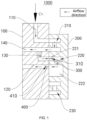
FIG. 1 is a structural schematic view of a conversion device provided in an embodiment of the present disclosure, with a valve cover being located in a first mounting position; and -
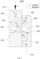
FIG. 2 is a structural schematic view of the conversion device provided in the embodiment of the present disclosure, with the valve cover being located in a second mounting position. - Reference signs: 1000-conversion device; 100-valve body; 200-valve cover; 110-valve body air inlet path; 120-first valve body air outlet path; 130-valve body passage; 140-second valve body air outlet path; 210-first valve cover passage; 220-second valve cover passage; 221-first port; 222-second port; 230-third valve cover passage; 300-first shrinkage member; 310-first flow-limiting channel; 400-second shrinkage member; 410-second flow-limiting channel; Cv-airflow.
- In order to make objectives, technical solutions, and advantages of the embodiments of the present disclosure clearer, the technical solutions in the embodiments of the present disclosure will be described clearly and completely below in conjunction with accompanying drawings in the embodiments of the present disclosure, and apparently, the embodiments described are some but not all embodiments of the present disclosure. Generally, components in the embodiments of the present disclosure, as described and shown in the accompanying drawings herein, may be arranged and designed in various different configurations.
- Therefore, the detailed description below of the embodiments of the present disclosure provided in the accompanying drawings is not intended to limit the scope of the present disclosure claimed, but merely illustrates chosen embodiments of the present disclosure. All of other embodiments obtained by those ordinarily skilled in the art based on the embodiments in the present disclosure without using inventive efforts shall fall within the scope of protection of the present disclosure.
- It should be noted that similar reference signs and letters represent similar items in the following accompanying drawings, therefore, once a certain item is defined in one accompanying drawing, it is not needed to be further defined or explained in subsequent accompanying drawings.
- In the description of the present disclosure, it should be indicated that orientation or positional relationships indicated by terms such as "upper", "lower", "inner", and "outer", if appear, are based on orientation or positional relationships as shown in the drawings, or orientation or positional relationships of a product of the present disclosure when being conventionally placed in use, merely for facilitating describing the present disclosure and simplifying the description, rather than indicating or suggesting that related devices or elements have to be in the specific orientation or configured and operated in a specific orientation, therefore, they should not be construed as limiting the present disclosure.
- Besides, terms such as "first" and "second", if appear, are merely for distinctive description, but should not be construed as indicating or implying importance in the relativity.
- It should be indicated that the features in the embodiments of the present disclosure may be combined with each other if there is no conflict.
- As one of the important transportation means in the transportation system, the trains play a great role. The speed of braking force output of the braking system of the trains is closely related to the braking demand of the trains, and meanwhile also will affect the running of the trains. Generally, a conversion device is added to the braking system so as to adjust the braking force output of the braking system.
- For example, for long-marshalling and slow-speed freight trains, it requires a relatively long time for the braking wave to be transmitted from front vehicles to rear vehicles. Generally, the braking force output is required to be slow, in this way it can be ensured that all of the front vehicles, middle vehicles, and rear vehicles of the marshalling train may be subjected to different degrees of braking force, and the longitudinal impulse of the train may be effectively reduced. If the braking system output is faster, when the vehicles of the marshalling train near the front have output the braking force, the braking force of the vehicles of the marshalling train near the back have not been output yet, this will cause a very large longitudinal impulse of the train, and will cause derailment of the vehicles in the most severe case.
- For short-marshalling and fast-speed express trains, it requires a short time for the braking wave to be transmitted from the front vehicles to the rear vehicles. Generally, the braking force is required to be output fast, in this way it ensures fast braking of the marshalling train, allowing the front and rear braking actions of the vehicles of the train to be consistent, effectively reducing the longitudinal impulse of the train, also greatly shortening an idling distance of the marshalling train, releasing a space of effective braking distance, and ensuring traveling safety of the vehicles.
- When heading for other destinations to load goods in an empty state, the express train usually will be mixed with long-marshalling train, then the problem of inconsistent braking force output will be highlighted. When the number of marshalling of the express train is large, the running of the train will be severely affected, therefore, a conversion device needs to be added to the braking system so as to adjust the braking force output of the braking system.
- In the prior art, the structure of the conversion device of the braking system of the train system is relatively complex.
- In view of this, a conversion device, a braking system, and a train provided in the embodiments of the present disclosure at least may solve this problem.
- Referring to
FIG. 1 to FIG. 2 , the present embodiment provides aconversion device 1000, a braking system, and a train, which will be described in detail below. - An embodiment of the present disclosure provides a train (not shown). The train may include a vehicle body (not shown) and a braking system (not shown), wherein the braking system may be mounted on the vehicle body. In the above, the braking system may include a
conversion device 1000, and in the braking system, an airflow Cv needs to be input into theconversion device 1000, theconversion device 1000 can change an output flow rate of the airflow Cv, and further control the speed of power output, and when the airflow Cv output by theconversion device 1000 is relatively slow, the braking output force of the braking system is relatively small, and when the airflow Cv output by theconversion device 1000 is relatively fast, the braking output force of the braking system is relatively large. - In the above, the
conversion device 1000 may include avalve body 100, avalve cover 200, and a first shrinkage (hole-reducing)member 300, thevalve body 100 may be provided thereon with a valve bodyair inlet path 110, a first valve bodyair outlet path 120, and avalve body passage 130, and thevalve cover 200 may be rotatably mounted on thevalve body 100. It may be understood that rotatably mounting thevalve cover 200 on thevalve body 100 can reduce the used space, and is more compact and simple. Certainly, in other embodiments, a protective cover further may be installed outside thevalve cover 200, in turn, misoperation of personnel may be avoided. - In the above, the
valve cover 200 may be provided thereon with a firstvalve cover passage 210, a secondvalve cover passage 220, and a thirdvalve cover passage 230; in the present embodiment, the structure of the firstvalve cover passage 210 and the structure of the secondvalve cover passage 220 may be the same. Thefirst shrinkage member 300 may be provided at afirst port 221 of the secondvalve cover passage 220; thevalve cover 200 may be configured to be rotatable relative to thevalve body 100, so as to be switched between a first mounting position and a second mounting position, and the switching between the first mounting position and the second mounting position in a rotating manner is also quite convenient. Specifically, the second mounting position may be that the valve cover is rotated 180 degrees clockwise or 180 degrees counterclockwise with respect to thevalve body 100 when thevalve cover 200 is in the first mounting position. - In the situation that the
valve cover 200 is in the first mounting position, the valve bodyair inlet path 110, the firstvalve cover passage 210, thevalve body passage 130, the secondvalve cover passage 220, and the first valve bodyair outlet path 120 may be in communication in sequence, afirst port 221 of the secondvalve cover passage 220 may be in communication with an air outlet end of thevalve body passage 130, asecond port 222 of the secondvalve cover passage 220 may be in communication with an air (gas) inlet end of the first valve bodyair outlet path 120, thefirst shrinkage member 300 may be configured to slow down the gas in thevalve body passage 130 from entering the secondvalve cover passage 220, two ports of the thirdvalve cover passage 230 may be configured to be blocked by a side wall of thevalve body 100, and at this time, thefirst shrinkage member 300 is also in a gas flow path, slowing down the velocity of the airflow Cv. - In the situation that the
valve cover 200 is in the second mounting position, the valve bodyair inlet path 110, the thirdvalve cover passage 230, thevalve body passage 130, the secondvalve cover passage 220, and the first valve body air outlet path may be in communication in sequence, thefirst port 221 of the secondvalve cover passage 220 may be configured to be blocked by the side wall of thevalve body 100, thesecond port 222 of the secondvalve cover passage 220 may be configured to make the air outlet end of thevalve body passage 130 in communication with the air inlet end of the first valve bodyair outlet path 120, two ports of the firstvalve cover passage 210 may be configured to be blocked by the side wall of thevalve body 100. In this case, since thefirst port 221 of the secondvalve cover passage 220 is configured to be blocked by the side wall of thevalve body 100, thefirst shrinkage member 300 is not in the gas flow path, increasing the velocity of the airflow Cv, that is, thefirst shrinkage member 300 is also blocked by the side wall of thevalve body 100, and it should be noted that thefirst shrinkage member 300 may be integrally molded with thevalve cover 200. - In the present embodiment, an air inlet direction of the
valve body 100 and an air outlet direction of thevalve body 100 may form an angle, and specifically, the air inlet direction of thevalve body 100 and the air outlet direction of thevalve body 100 may be perpendicular to each other. - In the above, the
valve body 100 may be provided thereon with a second valve bodyair outlet path 140, and an air inlet end of the second valve bodyair outlet path 140 may be in communication with thevalve body passage 130. It may be understood that, in this case, the airflow Cv may flow out simultaneously from the first valve bodyair outlet path 120 and the second valve bodyair outlet path 140. - The air inlet end of the first valve body
air outlet path 120 may be provided with asecond shrinkage member 400, and thesecond shrinkage member 400 may be configured to slow down the gas in thesecond port 222 of the secondvalve cover passage 220 from entering the first valve bodyair outlet path 120. It may be understood that thesecond shrinkage member 400 may be integrally molded with thevalve body 100, and at this time, in the first mounting position, the airflow Cv in theconversion device 1000 may pass through thefirst shrinkage member 300 and thesecond shrinkage member 400 and then flow out from the air outlet end of the first valve bodyair outlet path 120. - An outer wall of the
second shrinkage member 400 and an inner wall of the air inlet end of the first valve bodyair outlet path 120 may be fitted to each other, and an inner wall of thesecond shrinkage member 400 may define a second flow-limitingchannel 410, the second flow-limitingchannel 410 may be configured to slow down the gas in thesecond port 222 of the secondvalve cover passage 220 from entering the first valve bodyair outlet path 120, an outer wall of thefirst shrinkage member 300 and an inner wall of thefirst port 221 may be fitted to each other, an inner wall of thefirst shrinkage member 300 may define a first flow-limitingchannel 310, and the first flow-limitingchannel 310 may be configured to slow down the gas in thevalve body passage 130 from entering the secondvalve cover passage 220. - In the above, the
second port 222 of the secondvalve cover passage 220 may be in a cavity structure. It may be understood that, when the airflow Cv enters the secondvalve cover passage 220 and then enters thesecond port 222, the resistance for the airflow Cv will change, and specifically, the resistance for the airflow Cv may be reduced. - The
conversion device 1000 may include thevalve body 100, thevalve cover 200, and thefirst shrinkage member 300, thevalve body 100 may be provided thereon with the valve bodyair inlet path 110, the first valve bodyair outlet path 120, and thevalve body passage 130; and thevalve cover 200 may be rotatably mounted on thevalve body 100. Rotatably mounting thevalve cover 200 on thevalve body 100 can reduce the used space, and is more compact and simple. - In the above, the
valve cover 200 may be provided thereon with the firstvalve cover passage 210, the secondvalve cover passage 220, and the thirdvalve cover passage 230; thefirst shrinkage member 300 may be provided at thefirst port 221 of the secondvalve cover passage 220; thevalve cover 200 may be configured to be rotatable relative to thevalve body 100, so as to be switched between a first mounting position and a second mounting position, and the switching between the first mounting position and the second mounting position in a rotating manner is quite convenient. - In the situation that the
valve cover 200 is in the first mounting position, the valve bodyair inlet path 110, the firstvalve cover passage 210, thevalve body passage 130, the secondvalve cover passage 220, and the first valve bodyair outlet path 120 may be in communication in sequence, thefirst port 221 of the secondvalve cover passage 220 may be in communication with the air outlet end of thevalve body passage 130, thesecond port 222 of the secondvalve cover passage 220 may be in communication with the air inlet end of the first valve bodyair outlet path 120; thefirst shrinkage member 300 may be configured to slow down the gas in thevalve body passage 130 from entering the secondvalve cover passage 220, two ports of the thirdvalve cover passage 230 may be configured to be blocked by the side wall of thevalve body 100, and at this time, thefirst shrinkage member 300 is also in the gas flow path, slowing down the velocity of the airflow Cv. - In the situation that the
valve cover 200 is in the second mounting position, the valve bodyair inlet path 110, the thirdvalve cover passage 230, thevalve body passage 130, the secondvalve cover passage 220, and the first valve bodyair outlet path 120 may be in communication in sequence, thefirst port 221 of the secondvalve cover passage 220 may be configured to be blocked by the side wall of thevalve body 100, thesecond port 222 of the secondvalve cover passage 220 may be configured to make the air outlet end of thevalve body passage 130 in communication with the air inlet end of the first valve bodyair outlet path 120, two ports of the firstvalve cover passage 210 may be configured to be blocked by the side wall of thevalve body 100. In this case, since thefirst port 221 of the secondvalve cover passage 220 is configured to be blocked by the side wall of thevalve body 100, thefirst shrinkage member 300 is also blocked by the side wall of thevalve body 100, and will not hinder the flow of the airflow Cv, increasing the velocity of the airflow Cv. - The braking system may include the
above conversion device 1000, which can make the structure compact and simple. - The train may include a vehicle body and the above braking system, and the braking system may be mounted on the vehicle body, which can make the structure compact and simple.
- The above-mentioned are merely specific embodiments of the present disclosure, but the scope of protection of the present disclosure is not limited thereto, and any modification or substitution that may be easily envisaged by those skilled in the present technical field within the technical scope disclosed in the present disclosure should fall within the scope of protection of the present disclosure. Therefore, the scope of protection of the present disclosure should be determined by the scope of protection of the appended claims.
- Embodiments of the present disclosure provide a conversion device, a braking system, and a train, relating to the field of trains. The conversion device includes a valve body, a valve cover, and a first shrinkage member, the valve body is provided with a valve body air inlet path, a first valve body air outlet path, and a valve body passage; the valve cover is rotatably mounted on the valve body, the valve cover is provided with a first valve cover passage, a second valve cover passage, and a third valve cover passage; the first shrinkage member is provided at a first port of the second valve cover passage; the valve cover is configured to be rotatable relative to the valve body, so as to be switched between a first mounting position and a second mounting position. Rotatably mounting the valve cover on the valve body can reduce the used space, and is more compact and simple.
- Besides, it may be understood that the valve body, the valve cover, the first shrinkage member, the conversion device, and the braking system in the present disclosure may be reproduced, and may be applied in a variety of industrial applications. For example, the valve body, the valve cover, the first shrinkage member, the conversion device, and the braking system in the present disclosure may be applied to transportation tools, such as trains.
Claims (11)
- A conversion device, comprising:a vehicle body (100), wherein the valve body (100) is provided with a valve body air inlet path (110), a first valve body air outlet path (120), and a valve body passage (130);a valve cover (200), wherein the valve cover (200) is rotatably mounted on the valve body (100); and the valve cover (200) is provided with a first valve cover passage (210), a second valve cover passage (220), and a third valve cover passage (230); anda first shrinkage member (300), wherein the first shrinkage member (300) is provided at a first port (221) of the second valve cover passage (220),the valve cover (200) is configured to be rotatable relative to the valve body (100), so as to be switched between a first mounting position and a second mounting position, whereinin a situation that the valve cover (200) is in the first mounting position, the valve body air inlet path (110), the first valve cover passage (210), the valve body passage (130), the second valve cover passage (220), and the first valve body air outlet path (120) are in communication with each other in sequence, a first port (221) of the second valve cover passage (220) is in communication with an air outlet end of the valve body passage (130), a second port (222) of the second valve cover passage (220) is in communication with an air inlet end of the first valve body air outlet path (120); the first shrinkage member (300) is configured to slow down a gas in the valve body passage (130) entering the second valve cover passage (220), and two ports of the third valve cover passage (230) are configured to be blocked by a side wall of the valve body (100); andin a situation that the valve cover (200) is in the second mounting position, the valve body air inlet path (110), the third valve cover passage (230), the valve body passage (130), the second valve cover passage (220), and the first valve body air outlet path (120) are in communication with each other in sequence, the first port (221) of the second valve cover passage (220) is configured to be blocked by the side wall of the valve body (100), the second port (222) of the second valve cover passage (220) is configured to make the air outlet end of the valve body passage (130) in communication with the air inlet end of the first valve body air outlet path (120), and two ports of the first valve cover passage (210) are configured to be blocked by the side wall of the valve body (100).
- The conversion device according to claim 1, wherein the valve body (100) is provided with a second valve body air outlet path (140), and an air inlet end of the second valve body air outlet path (140) is in communication with the valve body passage (130).
- The conversion device according to claim 1 or 2, wherein the air inlet end of the first valve body air outlet path (120) is provided with a second shrinkage member (400), and the second shrinkage member (400) is configured to slow down gas in the second port (222) of the second valve cover passage (220) entering the first valve body air outlet path (120).
- The conversion device according to claim 3, wherein an outer wall of the second shrinkage member (400) and an inner wall of the air inlet end of the first valve body air outlet path (120) are fitted to each other, an inner wall of the second shrinkage member (400) defines a second flow-limiting channel (410), wherein the second flow-limiting channel (410) is configured to slow down the gas in the second port (222) of the second valve cover passage (220) entering the first valve body air outlet path (120).
- The conversion device according to any one of claims 1 to 4, wherein an outer wall of the first shrinkage member (300) and an inner wall of the first port (221) are fitted to each other, an inner wall of the first shrinkage member (300) defines a first flow-limiting channel (310), and the first flow-limiting channel (310) is configured to slow down the gas in the valve body passage (130) entering the second valve cover passage (220).
- The conversion device according to any one of claims 1 to 5, wherein the second port (222) of the second valve cover passage (220) is in a cavity structure.
- The conversion device according to any one of claims 1 to 6, wherein structure of the first valve cover passage (210) and structure of the second valve cover passage (220) are the same.
- The conversion device according to any one of claims 1 to 7, wherein an air inlet direction of the valve body (100) and an air outlet direction of the valve body (100) form an angle therebetween.
- The conversion device according to any one of claims 1 to 8, wherein a protective cover is installed outside the valve cover (200).
- A braking system, comprising the conversion device according to any one of claims 1-9.
- A train, comprising a vehicle body and the braking system according to claim 10, wherein the braking system is mounted on the vehicle body.
Applications Claiming Priority (2)
| Application Number | Priority Date | Filing Date | Title |
|---|---|---|---|
| CN202111123610.7A CN113803312B (en) | 2021-09-24 | 2021-09-24 | Conversion device, brake system and train |
| PCT/CN2021/126187 WO2023045010A1 (en) | 2021-09-24 | 2021-10-25 | Conversion device, braking system, and train |
Publications (3)
| Publication Number | Publication Date |
|---|---|
| EP4177480A1 true EP4177480A1 (en) | 2023-05-10 |
| EP4177480A4 EP4177480A4 (en) | 2023-08-09 |
| EP4177480B1 EP4177480B1 (en) | 2024-02-28 |
Family
ID=78940403
Family Applications (1)
| Application Number | Title | Priority Date | Filing Date |
|---|---|---|---|
| EP21809892.9A Active EP4177480B1 (en) | 2021-09-24 | 2021-10-25 | Conversion device, braking system, and train |
Country Status (4)
| Country | Link |
|---|---|
| EP (1) | EP4177480B1 (en) |
| CN (1) | CN113803312B (en) |
| HU (1) | HUE066926T2 (en) |
| WO (1) | WO2023045010A1 (en) |
Family Cites Families (16)
| Publication number | Priority date | Publication date | Assignee | Title |
|---|---|---|---|---|
| DE3427422A1 (en) * | 1983-07-26 | 1985-02-07 | Linde Ag, 6200 Wiesbaden | Control device for a drive |
| DE4232586A1 (en) * | 1992-09-23 | 1994-03-24 | Mannesmann Ag | Switching valve with regulation of output pressure - has inlet valve stage that closes when output pressure exceeds reference with vent valve stage opening to control pressure |
| US6135573A (en) * | 1998-06-29 | 2000-10-24 | Westinghouse Air Brake Company | 26-type electronic controlled pneumatic conversion block |
| US6086163A (en) * | 1998-09-25 | 2000-07-11 | Tsm, Inc. | Electronic interface manifold adapter for railroad passenger cars |
| CN2839686Y (en) * | 2005-10-13 | 2006-11-22 | 何贤能 | Automatic hydraulic flow regulating valve |
| CN201002603Y (en) * | 2006-12-12 | 2008-01-09 | 中国南车集团眉山车辆厂 | Braking controller for railway vehicle |
| EA019456B1 (en) * | 2010-09-20 | 2014-03-31 | Кнорр-Бремзе Зюстеме Фюр Шиненфарцойге Гмбх | Control valve comprising switching means for switching between characteristic curves of brake pressure |
| CN103470816B (en) * | 2013-09-16 | 2015-09-09 | 四川制动科技股份有限公司 | A kind of quick Control Valves for Freight Cars visitor/goods switching mechanism |
| CN104358925B (en) * | 2014-10-16 | 2017-10-13 | 眉山中车制动科技股份有限公司 | The stifled transformational structure of one kind contracting |
| CN104405712B (en) * | 2014-11-26 | 2016-08-24 | 眉山中车制动科技股份有限公司 | A kind of passenger-cargo switching valve |
| CN104482245B (en) * | 2014-12-09 | 2016-08-17 | 眉山中车制动科技股份有限公司 | A kind of railway brake valve is with fast general switching mechanism |
| CN106051213B (en) * | 2016-07-27 | 2018-01-30 | 眉山中车制动科技股份有限公司 | A kind of rolling stock alleviation adjustment valve |
| KR101926938B1 (en) * | 2016-12-26 | 2018-12-10 | 한국로봇융합연구원 | Small hydraulic system integrated with motor and pump and built-in hydraulic curcuit |
| CN108488125B (en) * | 2018-03-21 | 2019-12-17 | 洛阳世英机械制造有限公司 | A multifunctional flashlight integrated rotary control valve |
| DE102018003000A1 (en) * | 2018-04-12 | 2019-10-17 | Festo Ag & Co. Kg | Compensating valve, valve system and pneumatic system |
| CN111749943B (en) * | 2020-06-23 | 2024-05-17 | 安徽合力股份有限公司 | Follow-up rotary oil way switching valve |
-
2021
- 2021-09-24 CN CN202111123610.7A patent/CN113803312B/en active Active
- 2021-10-25 WO PCT/CN2021/126187 patent/WO2023045010A1/en not_active Ceased
- 2021-10-25 EP EP21809892.9A patent/EP4177480B1/en active Active
- 2021-10-25 HU HUE21809892A patent/HUE066926T2/en unknown
Also Published As
| Publication number | Publication date |
|---|---|
| WO2023045010A1 (en) | 2023-03-30 |
| CN113803312B (en) | 2022-04-29 |
| EP4177480A4 (en) | 2023-08-09 |
| HUE066926T2 (en) | 2024-09-28 |
| EP4177480B1 (en) | 2024-02-28 |
| CN113803312A (en) | 2021-12-17 |
Similar Documents
| Publication | Publication Date | Title |
|---|---|---|
| US3570515A (en) | Aminar stream cross-flow fluid diffusion logic gate | |
| US3984819A (en) | Data processing interconnection techniques | |
| Leitmann | On a class of variational problems in rocket flight | |
| EP4177480B1 (en) | Conversion device, braking system, and train | |
| GB1305813A (en) | ||
| WO2008057026A3 (en) | Providing safety in relation to mobile stations | |
| JPS63240460A (en) | Hydraulic brake circuit for aircraft | |
| Oliver et al. | Queuing for gaps in high flow traffic streams | |
| US3371675A (en) | Fluid amplifier | |
| US3643039A (en) | Multiple pitch carriage line spacing | |
| CN104954897A (en) | Novel vehicle-mounted intercom system | |
| US20030116961A1 (en) | Unitary multi-flow connection | |
| US5567992A (en) | Arrangement for a cruise control system for a motor vehicle | |
| WO2024153915A3 (en) | Systems and methods for directing fluid | |
| US3376882A (en) | Fluid logic anti-coincidence device by cancellation | |
| KR20120004813U (en) | The ship | |
| CN205632990U (en) | Two -way ship that cruises | |
| US3739814A (en) | Laminar flow wall attachment fluid logic device | |
| JP2018078711A (en) | Train system on train | |
| Greig | Notes on message switching systems | |
| US3562507A (en) | Pure fluid shift register | |
| JPH089329B2 (en) | Carrier control device | |
| CN207106416U (en) | A kind of carrier-and-stacker electric-control system | |
| Hsu | Construction of type b) XIP-neofields | |
| Swaczyna et al. | Interaction of Interstellar Clouds in the Solar Neighborhood |
Legal Events
| Date | Code | Title | Description |
|---|---|---|---|
| STAA | Information on the status of an ep patent application or granted ep patent |
Free format text: STATUS: UNKNOWN |
|
| STAA | Information on the status of an ep patent application or granted ep patent |
Free format text: STATUS: THE INTERNATIONAL PUBLICATION HAS BEEN MADE |
|
| PUAI | Public reference made under article 153(3) epc to a published international application that has entered the european phase |
Free format text: ORIGINAL CODE: 0009012 |
|
| STAA | Information on the status of an ep patent application or granted ep patent |
Free format text: STATUS: REQUEST FOR EXAMINATION WAS MADE |
|
| 17P | Request for examination filed |
Effective date: 20211129 |
|
| AK | Designated contracting states |
Kind code of ref document: A1 Designated state(s): AL AT BE BG CH CY CZ DE DK EE ES FI FR GB GR HR HU IE IS IT LI LT LU LV MC MK MT NL NO PL PT RO RS SE SI SK SM TR |
|
| A4 | Supplementary search report drawn up and despatched |
Effective date: 20230706 |
|
| RIC1 | Information provided on ipc code assigned before grant |
Ipc: F16K 11/00 20060101ALI20230630BHEP Ipc: F15B 13/02 20060101AFI20230630BHEP |
|
| GRAP | Despatch of communication of intention to grant a patent |
Free format text: ORIGINAL CODE: EPIDOSNIGR1 |
|
| STAA | Information on the status of an ep patent application or granted ep patent |
Free format text: STATUS: GRANT OF PATENT IS INTENDED |
|
| INTG | Intention to grant announced |
Effective date: 20230927 |
|
| GRAS | Grant fee paid |
Free format text: ORIGINAL CODE: EPIDOSNIGR3 |
|
| GRAA | (expected) grant |
Free format text: ORIGINAL CODE: 0009210 |
|
| STAA | Information on the status of an ep patent application or granted ep patent |
Free format text: STATUS: THE PATENT HAS BEEN GRANTED |
|
| AK | Designated contracting states |
Kind code of ref document: B1 Designated state(s): AL AT BE BG CH CY CZ DE DK EE ES FI FR GB GR HR HU IE IS IT LI LT LU LV MC MK MT NL NO PL PT RO RS SE SI SK SM TR |
|
| DAV | Request for validation of the european patent (deleted) | ||
| DAX | Request for extension of the european patent (deleted) | ||
| REG | Reference to a national code |
Ref country code: GB Ref legal event code: FG4D |
|
| REG | Reference to a national code |
Ref country code: CH Ref legal event code: EP |
|
| REG | Reference to a national code |
Ref country code: DE Ref legal event code: R096 Ref document number: 602021009925 Country of ref document: DE |
|
| REG | Reference to a national code |
Ref country code: IE Ref legal event code: FG4D |
|
| REG | Reference to a national code |
Ref country code: SE Ref legal event code: TRGR |
|
| REG | Reference to a national code |
Ref country code: LT Ref legal event code: MG9D |
|
| PG25 | Lapsed in a contracting state [announced via postgrant information from national office to epo] |
Ref country code: IS Free format text: LAPSE BECAUSE OF FAILURE TO SUBMIT A TRANSLATION OF THE DESCRIPTION OR TO PAY THE FEE WITHIN THE PRESCRIBED TIME-LIMIT Effective date: 20240628 |
|
| REG | Reference to a national code |
Ref country code: NL Ref legal event code: MP Effective date: 20240228 |
|
| PG25 | Lapsed in a contracting state [announced via postgrant information from national office to epo] |
Ref country code: LT Free format text: LAPSE BECAUSE OF FAILURE TO SUBMIT A TRANSLATION OF THE DESCRIPTION OR TO PAY THE FEE WITHIN THE PRESCRIBED TIME-LIMIT Effective date: 20240228 |
|
| PG25 | Lapsed in a contracting state [announced via postgrant information from national office to epo] |
Ref country code: GR Free format text: LAPSE BECAUSE OF FAILURE TO SUBMIT A TRANSLATION OF THE DESCRIPTION OR TO PAY THE FEE WITHIN THE PRESCRIBED TIME-LIMIT Effective date: 20240529 |
|
| PG25 | Lapsed in a contracting state [announced via postgrant information from national office to epo] |
Ref country code: HR Free format text: LAPSE BECAUSE OF FAILURE TO SUBMIT A TRANSLATION OF THE DESCRIPTION OR TO PAY THE FEE WITHIN THE PRESCRIBED TIME-LIMIT Effective date: 20240228 Ref country code: NL Free format text: LAPSE BECAUSE OF FAILURE TO SUBMIT A TRANSLATION OF THE DESCRIPTION OR TO PAY THE FEE WITHIN THE PRESCRIBED TIME-LIMIT Effective date: 20240228 Ref country code: RS Free format text: LAPSE BECAUSE OF FAILURE TO SUBMIT A TRANSLATION OF THE DESCRIPTION OR TO PAY THE FEE WITHIN THE PRESCRIBED TIME-LIMIT Effective date: 20240528 |
|
| PG25 | Lapsed in a contracting state [announced via postgrant information from national office to epo] |
Ref country code: ES Free format text: LAPSE BECAUSE OF FAILURE TO SUBMIT A TRANSLATION OF THE DESCRIPTION OR TO PAY THE FEE WITHIN THE PRESCRIBED TIME-LIMIT Effective date: 20240228 |
|
| PG25 | Lapsed in a contracting state [announced via postgrant information from national office to epo] |
Ref country code: RS Free format text: LAPSE BECAUSE OF FAILURE TO SUBMIT A TRANSLATION OF THE DESCRIPTION OR TO PAY THE FEE WITHIN THE PRESCRIBED TIME-LIMIT Effective date: 20240528 Ref country code: NO Free format text: LAPSE BECAUSE OF FAILURE TO SUBMIT A TRANSLATION OF THE DESCRIPTION OR TO PAY THE FEE WITHIN THE PRESCRIBED TIME-LIMIT Effective date: 20240528 Ref country code: NL Free format text: LAPSE BECAUSE OF FAILURE TO SUBMIT A TRANSLATION OF THE DESCRIPTION OR TO PAY THE FEE WITHIN THE PRESCRIBED TIME-LIMIT Effective date: 20240228 Ref country code: LT Free format text: LAPSE BECAUSE OF FAILURE TO SUBMIT A TRANSLATION OF THE DESCRIPTION OR TO PAY THE FEE WITHIN THE PRESCRIBED TIME-LIMIT Effective date: 20240228 Ref country code: IS Free format text: LAPSE BECAUSE OF FAILURE TO SUBMIT A TRANSLATION OF THE DESCRIPTION OR TO PAY THE FEE WITHIN THE PRESCRIBED TIME-LIMIT Effective date: 20240628 Ref country code: HR Free format text: LAPSE BECAUSE OF FAILURE TO SUBMIT A TRANSLATION OF THE DESCRIPTION OR TO PAY THE FEE WITHIN THE PRESCRIBED TIME-LIMIT Effective date: 20240228 Ref country code: GR Free format text: LAPSE BECAUSE OF FAILURE TO SUBMIT A TRANSLATION OF THE DESCRIPTION OR TO PAY THE FEE WITHIN THE PRESCRIBED TIME-LIMIT Effective date: 20240529 Ref country code: FI Free format text: LAPSE BECAUSE OF FAILURE TO SUBMIT A TRANSLATION OF THE DESCRIPTION OR TO PAY THE FEE WITHIN THE PRESCRIBED TIME-LIMIT Effective date: 20240228 Ref country code: ES Free format text: LAPSE BECAUSE OF FAILURE TO SUBMIT A TRANSLATION OF THE DESCRIPTION OR TO PAY THE FEE WITHIN THE PRESCRIBED TIME-LIMIT Effective date: 20240228 Ref country code: BG Free format text: LAPSE BECAUSE OF FAILURE TO SUBMIT A TRANSLATION OF THE DESCRIPTION OR TO PAY THE FEE WITHIN THE PRESCRIBED TIME-LIMIT Effective date: 20240228 |
|
| PG25 | Lapsed in a contracting state [announced via postgrant information from national office to epo] |
Ref country code: PT Free format text: LAPSE BECAUSE OF FAILURE TO SUBMIT A TRANSLATION OF THE DESCRIPTION OR TO PAY THE FEE WITHIN THE PRESCRIBED TIME-LIMIT Effective date: 20240628 Ref country code: PL Free format text: LAPSE BECAUSE OF FAILURE TO SUBMIT A TRANSLATION OF THE DESCRIPTION OR TO PAY THE FEE WITHIN THE PRESCRIBED TIME-LIMIT Effective date: 20240228 |
|
| REG | Reference to a national code |
Ref country code: AT Ref legal event code: MK05 Ref document number: 1661493 Country of ref document: AT Kind code of ref document: T Effective date: 20240228 |
|
| PG25 | Lapsed in a contracting state [announced via postgrant information from national office to epo] |
Ref country code: PT Free format text: LAPSE BECAUSE OF FAILURE TO SUBMIT A TRANSLATION OF THE DESCRIPTION OR TO PAY THE FEE WITHIN THE PRESCRIBED TIME-LIMIT Effective date: 20240628 Ref country code: PL Free format text: LAPSE BECAUSE OF FAILURE TO SUBMIT A TRANSLATION OF THE DESCRIPTION OR TO PAY THE FEE WITHIN THE PRESCRIBED TIME-LIMIT Effective date: 20240228 Ref country code: LV Free format text: LAPSE BECAUSE OF FAILURE TO SUBMIT A TRANSLATION OF THE DESCRIPTION OR TO PAY THE FEE WITHIN THE PRESCRIBED TIME-LIMIT Effective date: 20240228 |
|
| REG | Reference to a national code |
Ref country code: HU Ref legal event code: AG4A Ref document number: E066926 Country of ref document: HU |
|
| PG25 | Lapsed in a contracting state [announced via postgrant information from national office to epo] |
Ref country code: DK Free format text: LAPSE BECAUSE OF FAILURE TO SUBMIT A TRANSLATION OF THE DESCRIPTION OR TO PAY THE FEE WITHIN THE PRESCRIBED TIME-LIMIT Effective date: 20240228 |
|
| PG25 | Lapsed in a contracting state [announced via postgrant information from national office to epo] |
Ref country code: SM Free format text: LAPSE BECAUSE OF FAILURE TO SUBMIT A TRANSLATION OF THE DESCRIPTION OR TO PAY THE FEE WITHIN THE PRESCRIBED TIME-LIMIT Effective date: 20240228 |
|
| PG25 | Lapsed in a contracting state [announced via postgrant information from national office to epo] |
Ref country code: EE Free format text: LAPSE BECAUSE OF FAILURE TO SUBMIT A TRANSLATION OF THE DESCRIPTION OR TO PAY THE FEE WITHIN THE PRESCRIBED TIME-LIMIT Effective date: 20240228 Ref country code: CZ Free format text: LAPSE BECAUSE OF FAILURE TO SUBMIT A TRANSLATION OF THE DESCRIPTION OR TO PAY THE FEE WITHIN THE PRESCRIBED TIME-LIMIT Effective date: 20240228 |
|
| PG25 | Lapsed in a contracting state [announced via postgrant information from national office to epo] |
Ref country code: AT Free format text: LAPSE BECAUSE OF FAILURE TO SUBMIT A TRANSLATION OF THE DESCRIPTION OR TO PAY THE FEE WITHIN THE PRESCRIBED TIME-LIMIT Effective date: 20240228 |
|
| PG25 | Lapsed in a contracting state [announced via postgrant information from national office to epo] |
Ref country code: SK Free format text: LAPSE BECAUSE OF FAILURE TO SUBMIT A TRANSLATION OF THE DESCRIPTION OR TO PAY THE FEE WITHIN THE PRESCRIBED TIME-LIMIT Effective date: 20240228 |
|
| PG25 | Lapsed in a contracting state [announced via postgrant information from national office to epo] |
Ref country code: SM Free format text: LAPSE BECAUSE OF FAILURE TO SUBMIT A TRANSLATION OF THE DESCRIPTION OR TO PAY THE FEE WITHIN THE PRESCRIBED TIME-LIMIT Effective date: 20240228 Ref country code: SK Free format text: LAPSE BECAUSE OF FAILURE TO SUBMIT A TRANSLATION OF THE DESCRIPTION OR TO PAY THE FEE WITHIN THE PRESCRIBED TIME-LIMIT Effective date: 20240228 Ref country code: RO Free format text: LAPSE BECAUSE OF FAILURE TO SUBMIT A TRANSLATION OF THE DESCRIPTION OR TO PAY THE FEE WITHIN THE PRESCRIBED TIME-LIMIT Effective date: 20240228 Ref country code: EE Free format text: LAPSE BECAUSE OF FAILURE TO SUBMIT A TRANSLATION OF THE DESCRIPTION OR TO PAY THE FEE WITHIN THE PRESCRIBED TIME-LIMIT Effective date: 20240228 Ref country code: DK Free format text: LAPSE BECAUSE OF FAILURE TO SUBMIT A TRANSLATION OF THE DESCRIPTION OR TO PAY THE FEE WITHIN THE PRESCRIBED TIME-LIMIT Effective date: 20240228 Ref country code: CZ Free format text: LAPSE BECAUSE OF FAILURE TO SUBMIT A TRANSLATION OF THE DESCRIPTION OR TO PAY THE FEE WITHIN THE PRESCRIBED TIME-LIMIT Effective date: 20240228 Ref country code: AT Free format text: LAPSE BECAUSE OF FAILURE TO SUBMIT A TRANSLATION OF THE DESCRIPTION OR TO PAY THE FEE WITHIN THE PRESCRIBED TIME-LIMIT Effective date: 20240228 |
|
| REG | Reference to a national code |
Ref country code: DE Ref legal event code: R097 Ref document number: 602021009925 Country of ref document: DE |
|
| PG25 | Lapsed in a contracting state [announced via postgrant information from national office to epo] |
Ref country code: IT Free format text: LAPSE BECAUSE OF FAILURE TO SUBMIT A TRANSLATION OF THE DESCRIPTION OR TO PAY THE FEE WITHIN THE PRESCRIBED TIME-LIMIT Effective date: 20240228 |
|
| PG25 | Lapsed in a contracting state [announced via postgrant information from national office to epo] |
Ref country code: IT Free format text: LAPSE BECAUSE OF FAILURE TO SUBMIT A TRANSLATION OF THE DESCRIPTION OR TO PAY THE FEE WITHIN THE PRESCRIBED TIME-LIMIT Effective date: 20240228 |
|
| PLBE | No opposition filed within time limit |
Free format text: ORIGINAL CODE: 0009261 |
|
| STAA | Information on the status of an ep patent application or granted ep patent |
Free format text: STATUS: NO OPPOSITION FILED WITHIN TIME LIMIT |
|
| 26N | No opposition filed |
Effective date: 20241129 |
|
| PG25 | Lapsed in a contracting state [announced via postgrant information from national office to epo] |
Ref country code: SI Free format text: LAPSE BECAUSE OF FAILURE TO SUBMIT A TRANSLATION OF THE DESCRIPTION OR TO PAY THE FEE WITHIN THE PRESCRIBED TIME-LIMIT Effective date: 20240228 |
|
| PG25 | Lapsed in a contracting state [announced via postgrant information from national office to epo] |
Ref country code: MC Free format text: LAPSE BECAUSE OF FAILURE TO SUBMIT A TRANSLATION OF THE DESCRIPTION OR TO PAY THE FEE WITHIN THE PRESCRIBED TIME-LIMIT Effective date: 20240228 |
|
| PG25 | Lapsed in a contracting state [announced via postgrant information from national office to epo] |
Ref country code: LU Free format text: LAPSE BECAUSE OF NON-PAYMENT OF DUE FEES Effective date: 20241025 Ref country code: BE Free format text: LAPSE BECAUSE OF NON-PAYMENT OF DUE FEES Effective date: 20241031 |
|
| PG25 | Lapsed in a contracting state [announced via postgrant information from national office to epo] |
Ref country code: FR Free format text: LAPSE BECAUSE OF NON-PAYMENT OF DUE FEES Effective date: 20241031 |
|
| REG | Reference to a national code |
Ref country code: BE Ref legal event code: MM Effective date: 20241031 |
|
| PG25 | Lapsed in a contracting state [announced via postgrant information from national office to epo] |
Ref country code: IE Free format text: LAPSE BECAUSE OF NON-PAYMENT OF DUE FEES Effective date: 20241025 |
|
| REG | Reference to a national code |
Ref country code: CH Ref legal event code: U11 Free format text: ST27 STATUS EVENT CODE: U-0-0-U10-U11 (AS PROVIDED BY THE NATIONAL OFFICE) Effective date: 20251101 |
|
| PGFP | Annual fee paid to national office [announced via postgrant information from national office to epo] |
Ref country code: HU Payment date: 20251020 Year of fee payment: 5 |
|
| PGFP | Annual fee paid to national office [announced via postgrant information from national office to epo] |
Ref country code: DE Payment date: 20251020 Year of fee payment: 5 |
|
| PGFP | Annual fee paid to national office [announced via postgrant information from national office to epo] |
Ref country code: TR Payment date: 20251022 Year of fee payment: 5 |
|
| PGFP | Annual fee paid to national office [announced via postgrant information from national office to epo] |
Ref country code: SE Payment date: 20251023 Year of fee payment: 5 Ref country code: CH Payment date: 20251101 Year of fee payment: 5 |
|
| PG25 | Lapsed in a contracting state [announced via postgrant information from national office to epo] |
Ref country code: CY Free format text: LAPSE BECAUSE OF FAILURE TO SUBMIT A TRANSLATION OF THE DESCRIPTION OR TO PAY THE FEE WITHIN THE PRESCRIBED TIME-LIMIT; INVALID AB INITIO Effective date: 20211025 |