EP4177453A1 - Stirling engine - Google Patents
Stirling engine Download PDFInfo
- Publication number
- EP4177453A1 EP4177453A1 EP22205636.8A EP22205636A EP4177453A1 EP 4177453 A1 EP4177453 A1 EP 4177453A1 EP 22205636 A EP22205636 A EP 22205636A EP 4177453 A1 EP4177453 A1 EP 4177453A1
- Authority
- EP
- European Patent Office
- Prior art keywords
- engine
- heat exchanger
- stirling engine
- heater
- cylinder
- Prior art date
- Legal status (The legal status is an assumption and is not a legal conclusion. Google has not performed a legal analysis and makes no representation as to the accuracy of the status listed.)
- Granted
Links
Images




Classifications
-
- F—MECHANICAL ENGINEERING; LIGHTING; HEATING; WEAPONS; BLASTING
- F02—COMBUSTION ENGINES; HOT-GAS OR COMBUSTION-PRODUCT ENGINE PLANTS
- F02G—HOT GAS OR COMBUSTION-PRODUCT POSITIVE-DISPLACEMENT ENGINE PLANTS; USE OF WASTE HEAT OF COMBUSTION ENGINES; NOT OTHERWISE PROVIDED FOR
- F02G1/00—Hot gas positive-displacement engine plants
- F02G1/04—Hot gas positive-displacement engine plants of closed-cycle type
- F02G1/043—Hot gas positive-displacement engine plants of closed-cycle type the engine being operated by expansion and contraction of a mass of working gas which is heated and cooled in one of a plurality of constantly communicating expansible chambers, e.g. Stirling cycle type engines
- F02G1/044—Hot gas positive-displacement engine plants of closed-cycle type the engine being operated by expansion and contraction of a mass of working gas which is heated and cooled in one of a plurality of constantly communicating expansible chambers, e.g. Stirling cycle type engines having at least two working members, e.g. pistons, delivering power output
-
- F—MECHANICAL ENGINEERING; LIGHTING; HEATING; WEAPONS; BLASTING
- F02—COMBUSTION ENGINES; HOT-GAS OR COMBUSTION-PRODUCT ENGINE PLANTS
- F02G—HOT GAS OR COMBUSTION-PRODUCT POSITIVE-DISPLACEMENT ENGINE PLANTS; USE OF WASTE HEAT OF COMBUSTION ENGINES; NOT OTHERWISE PROVIDED FOR
- F02G1/00—Hot gas positive-displacement engine plants
- F02G1/04—Hot gas positive-displacement engine plants of closed-cycle type
- F02G1/043—Hot gas positive-displacement engine plants of closed-cycle type the engine being operated by expansion and contraction of a mass of working gas which is heated and cooled in one of a plurality of constantly communicating expansible chambers, e.g. Stirling cycle type engines
- F02G1/053—Component parts or details
- F02G1/055—Heaters or coolers
-
- F—MECHANICAL ENGINEERING; LIGHTING; HEATING; WEAPONS; BLASTING
- F02—COMBUSTION ENGINES; HOT-GAS OR COMBUSTION-PRODUCT ENGINE PLANTS
- F02G—HOT GAS OR COMBUSTION-PRODUCT POSITIVE-DISPLACEMENT ENGINE PLANTS; USE OF WASTE HEAT OF COMBUSTION ENGINES; NOT OTHERWISE PROVIDED FOR
- F02G1/00—Hot gas positive-displacement engine plants
- F02G1/04—Hot gas positive-displacement engine plants of closed-cycle type
- F02G1/043—Hot gas positive-displacement engine plants of closed-cycle type the engine being operated by expansion and contraction of a mass of working gas which is heated and cooled in one of a plurality of constantly communicating expansible chambers, e.g. Stirling cycle type engines
- F02G1/053—Component parts or details
- F02G1/057—Regenerators
-
- F—MECHANICAL ENGINEERING; LIGHTING; HEATING; WEAPONS; BLASTING
- F02—COMBUSTION ENGINES; HOT-GAS OR COMBUSTION-PRODUCT ENGINE PLANTS
- F02N—STARTING OF COMBUSTION ENGINES; STARTING AIDS FOR SUCH ENGINES, NOT OTHERWISE PROVIDED FOR
- F02N11/00—Starting of engines by means of electric motors
- F02N11/08—Circuits specially adapted for starting of engines
Definitions
- the present invention relates to a Stirling engine.
- a Stirling engine can recover motive power from a wide variety of high temperature heat sources.
- the Stirling engine has attracted attention as an exhaust heat recovery/power generation technique from existing high-temperature exhaust heat (from waste incineration plants, factory furnaces, and the like).
- spaces of a heater heat exchanger, a regenerator, and a cooler heat exchanger are connected in this order to a high-temperature space (expansion space) above the piston.
- the Stirling engine generates motive power by inserting a heater heat exchanger into a high-temperature heat source and absorbing heat therefrom.
- Patent Documents 1 to 3 Conventional Stirling engines (for example, Patent Documents 1 to 3) are structured such that a heater heat exchanger is directly connected to an expansion space and a regenerator, and the heater heat exchanger and the engine (including the expansion space) are arranged in proximity to each other.
- An object of the present invention is to provide a Stirling engine having a high degree of freedom in installation of a heater heat exchanger.
- a Stirling engine of the present invention is a Stirling engine including an engine unit, a heater heat exchanger, a regenerator, and a cooler heat exchanger.
- An engine main body including at least the engine unit and the cooler heat exchanger and a heater structure including at least the heater heat exchanger are separately structured.
- the engine main body and the heater structure are connected via a coupling pipe portion.
- the positional relationship between the engine main body and the heater structure can be easily changed by altering the shape of the coupling pipe portion (for example, by replacing the coupling pipe portion).
- the degree of freedom in installation of the heater heat exchanger is increased, so that the heater heat exchanger can be easily installed in a wide variety of high temperature heat sources.
- the regenerator and the cooler heat exchanger may be arranged behind a cylinder, and an upper end position of the regenerator may be above an upper end position of the cylinder.
- the Stirling engine may be a double-acting engine in which a plurality of cylinders is arranged linearly with respect to a crankshaft of the engine unit.
- the heater thin tube group for a plurality of cylinders may be arranged in an annular shape.
- the compact arrangement of the heater thin tube group can be realized by annularly arranging the heater thin tube group for the plurality of cylinders in the heater heat exchanger.
- the Stirling engine may be arranged such that a longitudinal direction of the heater heat exchanger intersects a sliding direction of a piston in the cylinder.
- the Stirling engine may include a first support member that holds the heater structure.
- the Stirling engine may include a second support member that holds the regenerator.
- the Stirling engine may include an on-off valve on a working fluid path connecting a low-temperature chamber of the cylinder and the cooler heat exchanger, and the working fluid path may be partially closed by the on-off valve during stoppage of the engine.
- the stop control of the engine can be safely performed using an inexpensive valve such as a butterfly valve.
- an inexpensive valve such as a butterfly valve.
- the on-off valve partially closes the working fluid path, it is possible to prevent a load (compression pressure) applied to the closed path from becoming too large, and avoid occurrence of damage to the components and the like.
- the Stirling engine may include a bypass path that connects low-temperature chambers of cylinders with a phase shift of 180°, and a communication valve provided on the bypass path, and the communication valve may be closed to close the bypass path during operation of the engine, and the communication valve may be opened to conduct the bypass path during stoppage of the engine.
- the Stirling engine can be configured such that the engine output is adjustable by controlling the on-off valve or the communication valve to an arbitrary opening degree during operation of the engine.
- the engine output is adjustable, when the temperature of the high-temperature heat source is excessively increased, for example, the engine output can be reduced to protect the components of the engine.
- the Stirling engine may include a starter motor for starting the engine, start the starter motor in a state where the communication valve is opened at a time of starting the engine, and close the communication valve after starting the engine to stop the starter motor.
- the engine load is reduced by opening the communication valve at the time of starting the engine, so that a small starter motor can be used.
- the regenerator may be included in the engine main body.
- both the regenerator and the cooler heat exchanger have a cylindrical similar shape, the regenerator is included in the engine main body, and the regenerator and the cooler heat exchanger are connected to each other in a constant manner, which is advantageous for downsizing the Stirling engine.
- each of the coupling pipes configuring the coupling pipe portion may be configured such that a heat storage is provided in the coupling pipe wall over the entire pipeline.
- connection pipe can have the same function as the regenerator by the heat storage action of the heat storage, so that the output of the Stirling engine can be improved by effectively using the heat.
- the heat storage may have a cavity portion in the center.
- the cavity portion serves as a passage for the working fluid, so that it is possible to restrain an increase in pressure loss due to the heat storage in the coupling pipe.
- the coupling pipe portion may be attachable to and detachable from the engine main body and the heater structure, and have a metal O-ring arranged on a sealing surface between the coupling pipe portion and a member to be connected.
- the coupling pipe portion is attachable to and detachable from the engine main body and the heater structure, the positional relationship between the engine main body and the heater structure can be easily changed, and the use of the metal O-ring enables sealing at a place requiring resistance to high temperatures.
- the engine main body and the heater structure have separate structures, and the engine main body and the heater structure are connected to each other via the coupling pipe portion, so that the degree of freedom in installation of the heater heat exchanger is increased, and the heater heat exchanger can be easily installed in a wide variety of high temperature heat sources.
- Figs. 1 and 2 are perspective views illustrating an outer appearance of a Stirling engine 10 according to a first embodiment.
- Fig. 3 is a schematic diagram illustrating a schematic configuration of the Stirling engine 10.
- the Stirling engine 10 includes an engine unit 11, a heater heat exchanger 12, a regenerator 13, a cooler heat exchanger 14, and a coupling pipe portion 15.
- a generator 20 is connected to a crankshaft 115 (see Fig. 3 ) of the engine unit 11, and the generator 20 can generate power by driving the Stirling engine 10.
- the heater heat exchanger 12 is inserted into a high-temperature heat source (for example, a high-temperature pipe through which a high-temperature fluid flows), and the working fluid is heated in the heater heat exchanger 12.
- a high-temperature heat source for example, a high-temperature pipe through which a high-temperature fluid flows
- the working fluid is heated in the heater heat exchanger 12.
- the cooler heat exchanger 14 the working fluid is cooled by cooling water (a cooling water supply unit is not illustrated).
- the Stirling engine 10 is designed to drive the engine unit 11 by the movement of the working fluid thus heated/cooled.
- the engine unit 11 may be a single-cylinder type engine or a multi-cylinder type engine, the four-cylinder type engine unit 11 is exemplified in the first embodiment.
- the engine unit 11 includes four cylinders 111A to 111D (simply referred to as cylinders 111 unless otherwise distinguished).
- four cylinders arranged linearly with respect to the crankshaft 115 are designated as the cylinders 111A to 111D according to the arrangement order.
- Each cylinder 111 includes a piston 112, a high-temperature chamber 113 on one side (upper side in Fig. 3 ) with respect to a sliding direction (up-down direction in Fig. 3 ) of the piston 112, and a low-temperature chamber 114 on the other side (lower side in Fig. 3 ).
- the high-temperature chamber 113 is connected to the heater heat exchanger 12, and the low-temperature chamber 114 is connected to the cooler heat exchanger 14.
- the heater heat exchanger 12 and the cooler heat exchanger 14 are connected with the regenerator 13 interposed therebetween.
- the regenerator 13 serves as a heat storage means between the heater heat exchanger 12 and the cooler heat exchanger 14, and stores heat from the working fluid when the working fluid moves from the heater heat exchanger 12 to the cooler heat exchanger 14 and causes the working fluid to recover the heat to the heater heat exchanger 12 in the opposite flow, thereby effectively utilizing the heat.
- the Stirling engine 10 illustrated in Fig. 3 is a four-cylinder double-acting engine, and the heater heat exchanger 12 and the cooler heat exchanger 14 connected with the same regenerator 13 interposed therebetween are connected to different cylinders 111.
- the operation of the Stirling engine 10 is established by repeating a cycle in which the pistons 112 in the cylinders 111 sequentially take a first position (a top dead center position: the cylinder 111A in Fig. 3 ), a second position (a position at which the crankshaft 115 is rotated by 90° from the top dead center position while the piston 112 moves downward: the cylinder 111D in Fig. 3 ), a third position (a bottom dead center position: the cylinder 111C in Fig. 3 ), and a fourth position (a position at which the crankshaft 115 is rotated 90° from the bottom dead center position while the piston 112 moves upward: the cylinder 111B in Fig. 3 ).
- the Stirling engine 10 is structurally characterized in that an engine main body E (see Fig. 4 ) including at least the engine unit 11 and the cooler heat exchanger 14 and a heater structure H (see Fig. 4 ) including at least the heater heat exchanger 12 are formed as separate structures, and are connected together via the coupling pipe portion 15.
- the regenerator 13 may be included in the engine main body E or may be included in the heater structure H. In the first embodiment, the regenerator 13 is included in the engine main body E as an example.
- the coupling pipe portion 15 includes a plurality of coupling pipes connecting the heater heat exchanger 12 and the regenerator 13 and a plurality of coupling pipes connecting the heater heat exchanger 12 and the high-temperature chambers 113 of the cylinders 111.
- the coupling pipe portion 15 includes a plurality of coupling pipes connecting the regenerator 13 and the cooler heat exchanger 14 and a plurality of coupling pipes connecting the heater heat exchanger 12 and the high-temperature chambers 113 of the cylinders 111.
- both the regenerator 13 and the cooler heat exchanger 14 have similar cylindrical shapes, integrally connecting them is advantageous to downsize the Stirling engine 10, and the regenerator 13 is preferably included in the engine main body E.
- the positional relationship between the engine main body E and the heater structure H can be easily changed by changing the shape of the coupling pipe portion 15 (for example, by replacing the coupling pipe portion 15). That is, the heater heat exchanger 12 can be easily installed in a wide variety of high-temperature heat sources.
- the heater structure H is arranged so as to extend laterally from the engine main body E.
- the high-temperature heat source in which the heater heat exchanger 12 is to be arranged is a high-temperature pipe 50A present on the side of the engine main body E
- the heater heat exchanger 12 can be easily installed in the high-temperature heat source.
- the heater structure H preferably extends upward rather than laterally from the engine main body E.
- the heater structure H can be easily arranged to extend upward from the engine main body E by changing the shape of the coupling pipe portion 15.
- the Stirling engine 10 preferably includes support members (for example, frames 31 and 32 in Fig. 1 ) that hold the engine main body E and the heater structure H.
- the frame 31 supports the heater heat exchanger 12 horizontally connected to the engine main body E, from an engine base 33 and the cylinder block of the engine unit 11.
- the frame 31 corresponds to the first support member described in the claims.
- the frame 32 connects the heater heat exchanger 12 and the regenerators 13, and also connects the regenerators 13 to each other and supports the regenerators 13.
- the frame 32 corresponds to the second support member described in the claims.
- a Stirling engine 10 is a four-cylinder double-acting engine. That is, as illustrated in Fig. 3 , in the Stirling engine 10, pistons 112 in four cylinders 111A to 111D are driven with a phase shift of 90° (specifically, the phases of the pistons 112 are delayed by 90° in the order of the cylinders 111A to 111D.).
- a reference cylinder for example, the cylinder 111A
- the other cylinders are defined as second to fourth cylinders in order of phase delay from the first cylinder
- the cylinder 111B is the second cylinder
- the cylinder 111C is the third cylinder
- the cylinder 111D is the fourth cylinder.
- a couple of forces is generated between two cylinders with a phase shift of 180°, and the couple of forces causes engine vibration or applies a load (bending stress) to the crankshaft.
- the four cylinders 111 are arranged in order from the first cylinder to the fourth cylinder.
- a couple of forces is generated between the first cylinder and the third cylinder and between the second cylinder and the fourth cylinder.
- the couple of forces generated in the crankshaft 115 is restrained (minimized) by adjusting the arrangement order of the cylinders.
- the cylinders with a phase shift of 180° are arranged close to (adjacent to) each other.
- the maximum couple of forces N for example, the couple of forces between the first cylinder and the third cylinder
- the first cylinder, the third cylinder, the fourth cylinder, and the second cylinder are arranged in this order in Fig. 6
- the order of the fourth cylinder and the second cylinder may be switched.
- the heater heat exchanger 12, the regenerator 13, and the cooler heat exchanger 14 as a set are connected between cylinders with a phase shift of 90°.
- a set of the heater heat exchanger 12, the regenerator 13, and the cooler heat exchanger 14 is connected between the cylinder 111A that is the first cylinder and the cylinder 111B that is the second cylinder.
- the cooler heat exchanger 14 is connected to the low-temperature chamber 114 of the cylinder 111A of which phase is advanced
- the heater heat exchanger 12 is connected to the high-temperature chamber 113 of the cylinder 111B of which phase is delayed.
- Fig. 3 illustrates the cylinder arrangement with respect to the crankshaft 115 in the order of the first to fourth cylinders (the arrangement order corresponding to Fig. 5 ).
- the cylinder arrangement is the order of the first cylinder, the third cylinder, the fourth cylinder, and the second cylinder (the arrangement order corresponding to Fig. 6 ) in order to reduce the load on the crankshaft 115, the connection of the heater heat exchanger 12, the regenerator 13, and the cooler heat exchanger 14 between the cylinders is schematically as illustrated in Fig. 7 .
- the heater heat exchanger 12 is configured with a heater thin tube group so that efficient heat exchange can be performed in a state of being inserted into a high-temperature heat source.
- the engine main body E and the heater structure H are separate structures and are connected via the coupling pipe portion 15. Therefore, as illustrated in Fig. 8 , the plurality of coupling pipes in the coupling pipe portion 15 enables the connection between the heater heat exchanger 12 and the regenerator 13 and the connection between the heater heat exchanger 12 and the high-temperature chamber 113 of each cylinder 111 with a high degree of freedom. As a result, the heater heat exchanger 12 can be compactly arranged in the heater thin tube group for four cylinders, regardless of the connection relationship with the regenerator 13 and the cylinder 111.
- the regenerator 13 and the cooler heat exchanger 14 are vertically placed close to each other at the rear of the cylinder 111, and an upper end position P1 of the regenerator 13 is above an upper end position P2 of the cylinder 111.
- the heater thin tube group for four cylinders is preferably arranged in an annular shape, as illustrated in Fig. 10 . This realizes compact arrangement of the heater thin tube group in the heater heat exchanger 12.
- the coupling pipe portion 15 can be configured such that a coupling pipe 150 as illustrated in Fig. 11 is individually connected (attachable to and detachable from the engine main body E and the heater structure H) between the heater heat exchanger 12 and the regenerator 13 or between the heater heat exchanger 12 and the cylinder 111.
- the coupling pipe 150 is preferably configured to obtain airtightness by arranging a metal O-ring 151 on a sealing surface between the coupling pipe 150 and a member (the heater heat exchanger 12, the regenerator 13, or the cylinder 111) to be connected.
- a metallic hollow O-ring gasket having resistance to high temperature or the like can be used.
- a Stirling engine 10 is a passive engine and basically continues to operate as long as heat is supplied from a high-temperature heat source (and stops operating when there is no supply of heat). However, it is also conceivable that the operation of the engine needs to be stopped in an emergency or the like. In a third embodiment, a preferred example of a configuration for stopping the Stirling engine 10 will be described.
- the Stirling engine 10 can stop by stopping the movement of a working fluid. Therefore, the Stirling engine 10 according to the third embodiment can be configured such that an on-off valve 16 (see Fig. 1 ) is provided in a low-temperature portion path of the working fluid (a working fluid path connecting a low-temperature chamber 114 of a cylinder 111 and a cooler heat exchanger 14), the on-off valve 16 is opened during the operation of the engine, and the engine is stopped by closing the on-off valve 16.
- the path provided with the on-off valve 16 is not particularly limited, and the on-off valve can be provided in a high-temperature portion path (a working fluid path connecting a high-temperature chamber 113 of the cylinder 111 and a heater heat exchanger 12).
- the high-temperature portion path configures a coupling pipe portion 15, so that the high-temperature portion path is unsuitable for arrangement of the on-off valve 16, and the on-off valve 16 is preferably provided on the low-temperature portion path.
- the type of the on-off valve 16 used is not particularly limited, and for example, an inexpensive valve such as a butterfly valve can be used.
- an inexpensive valve such as a butterfly valve
- the on-off valve 16 does not completely close the path, and is a perforated valve that can allow the working fluid to pass to some extent (partially close the path). That is, even if the on-off valve 16 does not completely close the path, the engine can be stopped only by decreasing the flow path area to reduce the movement amount of the working fluid. More specifically, the path closing area of the on-off valve 16 is set to a maximum area in which the engine is not damaged under the compression pressure generated by the closing the valve and in which the engine can be reliably stopped (engine output ⁇ mechanical loss).
- the on-off valve 16 may be configured to adjust the flow path area using a rotary solenoid or the like. In this case, it is possible to perform control to gradually reduce the flow path area, and it is possible to avoid a sudden stop of the engine and reduce a load or the like applied to pistons 112 when the engine is stopped.
- a Stirling engine 10 illustrated in Fig. 12 is configured such that low-temperature chambers 114 of cylinders 111 with phase shifts of 180° are connected to each other by bypass paths 17, and communication valves 171 are provided in the bypass paths 17.
- a cylinder 111A and a cylinder 111C are connected by the bypass path 17, and a cylinder 111B and a cylinder 111D are connected by the bypass path 17.
- the communication valves 171 are closed during the operation of the engine, and the communication valves 171 are opened to make the bypass paths 17 conductive (provide communication between the low-temperature chambers 114 of the cylinders 111 with a phase shift of 180°), whereby the engine can be stopped. In this configuration, it is possible to promptly stop the engine without applying an overload to components or the like.
- the opening degree of the on-off valves 16 and the communication valves 171 can be adjusted, so that the Stirling engine 10 can be used for output control of the engine.
- the on-off valves 16 are somewhat closed, or the communication valves 171 are somewhat opened, so that it is possible to reduce the engine output and protect the components of the engine.
- the Stirling engine 10 requires a starter motor 40 (see Fig. 1 ) at its startup.
- a starter motor 40 see Fig. 1
- the larger the engine load (pressure loss) at the startup of the Stirling engine 10 the larger the size of the starter motor 40 is required.
- the Stirling engine 10 according to the fourth embodiment is assumed to have the configuration illustrated in Fig. 12 , and is characterized by reducing the engine load at the time of startup using communication valves 171. That is, in the Stirling engine 10 according to the fourth embodiment, the starter motor 40 is started with the communication valves 171 opened at the time of startup. In the Stirling engine 10, since the engine load is reduced by opening the communication valves 171, the small-sized starter motor 40 can be used. Then, when the rotation speed of the engine reaches a predetermined value, the communication valves 171 are closed and the starter motor 40 is stopped, so that the operation of the engine can be maintained.
- the Stirling engine 10 described above is characterized in that the engine main body E and the heater structure H are formed as separate structures, and they are connected via the coupling pipe portion 15.
- the coupling pipe portion 15 becomes an ineffective volume that does not contribute to the thermal cycle, which may cause a decrease in the output of the Stirling engine 10.
- a preferred example for restraining a decrease in output due to the coupling pipe portion 15 will be described.
- Fig. 13 is a cross-sectional view of a coupling pipe 150 for use in the coupling pipe portion 15.
- a heat accumulator 153 such as a wire mesh or a metal nonwoven fabric is provided inside the coupling pipe wall 152 over the entire pipeline.
- the central portion of the heat accumulator 153 is preferably a cavity portion 154.
- the coupling pipe 150 configured in this manner can accumulate heat in the heat accumulator 153 and reduce heat dissipation to the outside when a high-temperature working fluid passes through the inside of the coupling pipe 150.
- the central portion of the heat accumulator 153 is formed as the cavity portion 154, the cavity portion 154 serves as a working fluid passage, so that it is possible to restrain an increase in pressure loss due to the heat accumulator 153.
- the coupling pipe 150 illustrated in Fig. 13 can have a function similar to that of a regenerator 13 by the heat accumulation action of the heat accumulator 153, so that the output of the Stirling engine 10 can be improved by effectively using the heat.
Landscapes
- Engineering & Computer Science (AREA)
- Chemical & Material Sciences (AREA)
- Combustion & Propulsion (AREA)
- Mechanical Engineering (AREA)
- General Engineering & Computer Science (AREA)
- Engine Equipment That Uses Special Cycles (AREA)
Abstract
Description
- The present invention relates to a Stirling engine.
- A Stirling engine can recover motive power from a wide variety of high temperature heat sources. In recent years, the Stirling engine has attracted attention as an exhaust heat recovery/power generation technique from existing high-temperature exhaust heat (from waste incineration plants, factory furnaces, and the like). In the Stirling engine, spaces of a heater heat exchanger, a regenerator, and a cooler heat exchanger are connected in this order to a high-temperature space (expansion space) above the piston. The Stirling engine generates motive power by inserting a heater heat exchanger into a high-temperature heat source and absorbing heat therefrom.
- Conventional Stirling engines (for example,
Patent Documents 1 to 3) are structured such that a heater heat exchanger is directly connected to an expansion space and a regenerator, and the heater heat exchanger and the engine (including the expansion space) are arranged in proximity to each other. -
- Patent Document 1:
JP-A-7-259646 - Patent Document 2:
JP-A-10-213012 - Patent Document 3:
Japanese Patent No. 5533713 - In the conventional Stirling engines, there is a problem that the degree of freedom of installation of the heater heat exchanger is small, and it is difficult to install the engine in accordance with various high temperature heat sources. For example, according to
Patent Document 1, since the heater heat exchanger is arranged in the piston sliding direction (on the cylinder axis) of the engine, if the pipe for the high-temperature heat source gas is installed just beside the engine, the heater heat exchanger cannot be inserted into the heat source pipe. - The present invention has been made in view of the above problem. An object of the present invention is to provide a Stirling engine having a high degree of freedom in installation of a heater heat exchanger.
- In order to solve the above problem, a Stirling engine of the present invention is a Stirling engine including an engine unit, a heater heat exchanger, a regenerator, and a cooler heat exchanger. An engine main body including at least the engine unit and the cooler heat exchanger and a heater structure including at least the heater heat exchanger are separately structured. The engine main body and the heater structure are connected via a coupling pipe portion.
- According to the above configuration, the positional relationship between the engine main body and the heater structure can be easily changed by altering the shape of the coupling pipe portion (for example, by replacing the coupling pipe portion). As a result, the degree of freedom in installation of the heater heat exchanger is increased, so that the heater heat exchanger can be easily installed in a wide variety of high temperature heat sources.
- In the Stirling engine, the regenerator and the cooler heat exchanger may be arranged behind a cylinder, and an upper end position of the regenerator may be above an upper end position of the cylinder.
- According to the above configuration, setting the upper end position of the regenerator above the upper end position of the cylinder makes it easy to secure the arrangement space of the coupling pipe portion among the regenerator, the cylinder, and the heater heat exchanger.
- The Stirling engine may be a double-acting engine in which a plurality of cylinders is arranged linearly with respect to a crankshaft of the engine unit.
- Further, in the Stirling engine, in the heater heat exchanger, the heater thin tube group for a plurality of cylinders may be arranged in an annular shape.
- According to the above configuration, the compact arrangement of the heater thin tube group can be realized by annularly arranging the heater thin tube group for the plurality of cylinders in the heater heat exchanger.
- The Stirling engine may be arranged such that a longitudinal direction of the heater heat exchanger intersects a sliding direction of a piston in the cylinder.
- The Stirling engine may include a first support member that holds the heater structure.
- The Stirling engine may include a second support member that holds the regenerator.
- The Stirling engine may include an on-off valve on a working fluid path connecting a low-temperature chamber of the cylinder and the cooler heat exchanger, and the working fluid path may be partially closed by the on-off valve during stoppage of the engine.
- According to the above configuration, the stop control of the engine can be safely performed using an inexpensive valve such as a butterfly valve. In addition, since the on-off valve partially closes the working fluid path, it is possible to prevent a load (compression pressure) applied to the closed path from becoming too large, and avoid occurrence of damage to the components and the like.
- The Stirling engine may include a bypass path that connects low-temperature chambers of cylinders with a phase shift of 180°, and a communication valve provided on the bypass path, and the communication valve may be closed to close the bypass path during operation of the engine, and the communication valve may be opened to conduct the bypass path during stoppage of the engine.
- According to the above configuration, since the low-temperature chambers of the cylinders with a phase shift of 180° communicate with each other, it is possible to promptly stop the engine without applying an overload to the components or the like when the engine is to be stopped.
- In addition, the Stirling engine can be configured such that the engine output is adjustable by controlling the on-off valve or the communication valve to an arbitrary opening degree during operation of the engine.
- According to the above configuration, since the engine output is adjustable, when the temperature of the high-temperature heat source is excessively increased, for example, the engine output can be reduced to protect the components of the engine.
- The Stirling engine may include a starter motor for starting the engine, start the starter motor in a state where the communication valve is opened at a time of starting the engine, and close the communication valve after starting the engine to stop the starter motor.
- According to the above configuration, the engine load is reduced by opening the communication valve at the time of starting the engine, so that a small starter motor can be used.
- In the Stirling engine, the regenerator may be included in the engine main body.
- According to the above configuration, since both the regenerator and the cooler heat exchanger have a cylindrical similar shape, the regenerator is included in the engine main body, and the regenerator and the cooler heat exchanger are connected to each other in a constant manner, which is advantageous for downsizing the Stirling engine.
- In the Stirling engine, each of the coupling pipes configuring the coupling pipe portion may be configured such that a heat storage is provided in the coupling pipe wall over the entire pipeline.
- According to the above configuration, the connection pipe can have the same function as the regenerator by the heat storage action of the heat storage, so that the output of the Stirling engine can be improved by effectively using the heat.
- In the Stirling engine, the heat storage may have a cavity portion in the center.
- According to the above configuration, the cavity portion serves as a passage for the working fluid, so that it is possible to restrain an increase in pressure loss due to the heat storage in the coupling pipe.
- In the Stirling engine, the coupling pipe portion may be attachable to and detachable from the engine main body and the heater structure, and have a metal O-ring arranged on a sealing surface between the coupling pipe portion and a member to be connected.
- According to the above configuration, since the coupling pipe portion is attachable to and detachable from the engine main body and the heater structure, the positional relationship between the engine main body and the heater structure can be easily changed, and the use of the metal O-ring enables sealing at a place requiring resistance to high temperatures.
- In the Stirling engine of the present invention, the engine main body and the heater structure have separate structures, and the engine main body and the heater structure are connected to each other via the coupling pipe portion, so that the degree of freedom in installation of the heater heat exchanger is increased, and the heater heat exchanger can be easily installed in a wide variety of high temperature heat sources.
-
-
Fig. 1 is a perspective view of an embodiment of the present invention, which illustrates an outer appearance of a Stirling engine; -
Fig. 2 is a perspective view of the Stirling engine ofFig. 1 as viewed from a different direction; -
Fig. 3 is a schematic diagram illustrating a schematic configuration of the Stirling engine; -
Fig. 4 is an explanatory diagram illustrating an example of a positional relationship between the Stirling engine and a high-temperature heat source; -
Fig. 5 is an explanatory diagram illustrating an example of a couple of forces acting on a crankshaft; -
Fig. 6 is an explanatory diagram illustrating a preferred example of a couple of forces acting on the crankshaft; -
Fig. 7 is a schematic diagram illustrating a schematic configuration of the Stirling engine; -
Fig. 8 is an enlarged perspective view of a coupling pipe portion in the Stirling engine; -
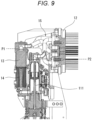
Fig. 9 is a diagram illustrating an arrangement relationship among a regenerator, a cooler heat exchanger, and cylinders in the Stirling engine; -
Fig. 10 is a plan view illustrating an arrangement example of a heater thin tube group in the heater heat exchanger; -
Fig. 11 is a perspective view illustrating an outer appearance example of a coupling pipe; -
Fig. 12 is a schematic diagram illustrating a schematic configuration of the Stirling engine; and -
Fig. 13 is a cross-sectional view of the coupling pipe. - Hereinafter, embodiments of the present invention will be described in detail with reference to the drawings.
Figs. 1 and2 are perspective views illustrating an outer appearance of aStirling engine 10 according to a first embodiment.Fig. 3 is a schematic diagram illustrating a schematic configuration of theStirling engine 10. - As illustrated in
Figs. 1 and2 , theStirling engine 10 includes anengine unit 11, aheater heat exchanger 12, aregenerator 13, acooler heat exchanger 14, and acoupling pipe portion 15. In addition, in theStirling engine 10 illustrated inFigs. 1 and2 , agenerator 20 is connected to a crankshaft 115 (seeFig. 3 ) of theengine unit 11, and thegenerator 20 can generate power by driving theStirling engine 10. - In the
Stirling engine 10, theheater heat exchanger 12 is inserted into a high-temperature heat source (for example, a high-temperature pipe through which a high-temperature fluid flows), and the working fluid is heated in theheater heat exchanger 12. In thecooler heat exchanger 14, the working fluid is cooled by cooling water (a cooling water supply unit is not illustrated). TheStirling engine 10 is designed to drive theengine unit 11 by the movement of the working fluid thus heated/cooled. Although theengine unit 11 may be a single-cylinder type engine or a multi-cylinder type engine, the four-cylindertype engine unit 11 is exemplified in the first embodiment. - As illustrated in
Fig. 3 , theengine unit 11 includes fourcylinders 111A to 111D (simply referred to ascylinders 111 unless otherwise distinguished). Here, four cylinders arranged linearly with respect to thecrankshaft 115 are designated as thecylinders 111A to 111D according to the arrangement order. Eachcylinder 111 includes apiston 112, a high-temperature chamber 113 on one side (upper side inFig. 3 ) with respect to a sliding direction (up-down direction inFig. 3 ) of thepiston 112, and a low-temperature chamber 114 on the other side (lower side inFig. 3 ). The high-temperature chamber 113 is connected to theheater heat exchanger 12, and the low-temperature chamber 114 is connected to thecooler heat exchanger 14. Theheater heat exchanger 12 and thecooler heat exchanger 14 are connected with theregenerator 13 interposed therebetween. Theregenerator 13 serves as a heat storage means between theheater heat exchanger 12 and thecooler heat exchanger 14, and stores heat from the working fluid when the working fluid moves from theheater heat exchanger 12 to thecooler heat exchanger 14 and causes the working fluid to recover the heat to theheater heat exchanger 12 in the opposite flow, thereby effectively utilizing the heat. TheStirling engine 10 illustrated inFig. 3 is a four-cylinder double-acting engine, and theheater heat exchanger 12 and thecooler heat exchanger 14 connected with thesame regenerator 13 interposed therebetween are connected todifferent cylinders 111. - The operation of the
Stirling engine 10 is established by repeating a cycle in which thepistons 112 in thecylinders 111 sequentially take a first position (a top dead center position: thecylinder 111A inFig. 3 ), a second position (a position at which thecrankshaft 115 is rotated by 90° from the top dead center position while thepiston 112 moves downward: thecylinder 111D inFig. 3 ), a third position (a bottom dead center position: thecylinder 111C inFig. 3 ), and a fourth position (a position at which thecrankshaft 115 is rotated 90° from the bottom dead center position while thepiston 112 moves upward: thecylinder 111B inFig. 3 ). - The
Stirling engine 10 according to the first embodiment is structurally characterized in that an engine main body E (seeFig. 4 ) including at least theengine unit 11 and thecooler heat exchanger 14 and a heater structure H (seeFig. 4 ) including at least theheater heat exchanger 12 are formed as separate structures, and are connected together via thecoupling pipe portion 15. Theregenerator 13 may be included in the engine main body E or may be included in the heater structure H. In the first embodiment, theregenerator 13 is included in the engine main body E as an example. In this case, thecoupling pipe portion 15 includes a plurality of coupling pipes connecting theheater heat exchanger 12 and theregenerator 13 and a plurality of coupling pipes connecting theheater heat exchanger 12 and the high-temperature chambers 113 of thecylinders 111. - If the
regenerator 13 is included in theheater heat exchanger 12, thecoupling pipe portion 15 includes a plurality of coupling pipes connecting theregenerator 13 and thecooler heat exchanger 14 and a plurality of coupling pipes connecting theheater heat exchanger 12 and the high-temperature chambers 113 of thecylinders 111. However, since both theregenerator 13 and thecooler heat exchanger 14 have similar cylindrical shapes, integrally connecting them is advantageous to downsize theStirling engine 10, and theregenerator 13 is preferably included in the engine main body E. - As described above, in the
Stirling engine 10 in which the engine main body E and the heater structure H are connected via thecoupling pipe portion 15, the positional relationship between the engine main body E and the heater structure H can be easily changed by changing the shape of the coupling pipe portion 15 (for example, by replacing the coupling pipe portion 15). That is, theheater heat exchanger 12 can be easily installed in a wide variety of high-temperature heat sources. - For example, in the example illustrated in
Fig. 4 , the heater structure H is arranged so as to extend laterally from the engine main body E. In a case where the high-temperature heat source in which theheater heat exchanger 12 is to be arranged is a high-temperature pipe 50A present on the side of the engine main body E, theheater heat exchanger 12 can be easily installed in the high-temperature heat source. However, in the case where the high-temperature heat source in which theheater heat exchanger 12 is to be arranged is a high-temperature pipe 50B existing above the engine main body E, the heater structure H preferably extends upward rather than laterally from the engine main body E. In theStirling engine 10 according to the first embodiment, the heater structure H can be easily arranged to extend upward from the engine main body E by changing the shape of thecoupling pipe portion 15. - In the
Stirling engine 10, if the engine main body E and the heater structure H are supported only by thecoupling pipe portion 15, there is a problem of strength. If the support strength in theStirling engine 10 is weak, the vibrations of the plurality ofcylinders 111 cannot be restrained, and the vibration of the entire engine increases. In addition, for example, as illustrated inFigs. 1 and2 , when the heater structure H has a lateral structure extending laterally from the engine main body E (in other words, a structure in which the longitudinal direction of theheater heat exchanger 12 is orthogonal to the sliding direction of thepiston 112 in the cylinder 111), an unbalanced load may be generated on thecoupling pipe portion 15 due to the weight of the heater structure H. - Therefore, the
Stirling engine 10 according to the present embodiment preferably includes support members (for example, frames 31 and 32 inFig. 1 ) that hold the engine main body E and the heater structure H. Theframe 31 supports theheater heat exchanger 12 horizontally connected to the engine main body E, from anengine base 33 and the cylinder block of theengine unit 11. Theframe 31 corresponds to the first support member described in the claims. Theframe 32 connects theheater heat exchanger 12 and theregenerators 13, and also connects theregenerators 13 to each other and supports theregenerators 13. Theframe 32 corresponds to the second support member described in the claims. These support members can restrain the vibration of theStirling engine 10. In addition, it is possible to adopt a heater lateral structure that cannot be realized by a conventional structure. - In a second embodiment, it is assumed that a
Stirling engine 10 is a four-cylinder double-acting engine. That is, as illustrated inFig. 3 , in theStirling engine 10,pistons 112 in fourcylinders 111A to 111D are driven with a phase shift of 90° (specifically, the phases of thepistons 112 are delayed by 90° in the order of thecylinders 111A to 111D.). When a reference cylinder (for example, thecylinder 111A) is defined as a first cylinder and the other cylinders are defined as second to fourth cylinders in order of phase delay from the first cylinder, in the example ofFig. 3 , thecylinder 111B is the second cylinder, thecylinder 111C is the third cylinder, and thecylinder 111D is the fourth cylinder. - In the case of a cylinder double-acting engine in which four cylinders are arranged linearly with respect to the
crankshaft 115, a couple of forces is generated between two cylinders with a phase shift of 180°, and the couple of forces causes engine vibration or applies a load (bending stress) to the crankshaft. In the example ofFig. 3 , the fourcylinders 111 are arranged in order from the first cylinder to the fourth cylinder. A couple of forces is generated between the first cylinder and the third cylinder and between the second cylinder and the fourth cylinder. In addition, as illustrated inFig. 5 , in a case where the force given to thecrankshaft 115 by the cylinder is F and the pitch between two adjacent cylinders is L, the maximum couple of forces N (for example, the couple of forces between the first cylinder and the third cylinder) acting on thecrankshaft 115 is N = 2FL. - On the other hand, in the second embodiment, the couple of forces generated in the
crankshaft 115 is restrained (minimized) by adjusting the arrangement order of the cylinders. Specifically, the cylinders with a phase shift of 180° are arranged close to (adjacent to) each other. For example, as illustrated inFig. 6 , when the first cylinder and the third cylinder are arranged adjacent to each other and the second cylinder and the fourth cylinder are arranged adjacent to each other, the maximum couple of forces N (for example, the couple of forces between the first cylinder and the third cylinder) acting on thecrankshaft 115 is N = FL. Although the first cylinder, the third cylinder, the fourth cylinder, and the second cylinder are arranged in this order inFig. 6 , the order of the fourth cylinder and the second cylinder may be switched. - In the four-cylinder double-acting engine, the
heater heat exchanger 12, theregenerator 13, and thecooler heat exchanger 14 as a set are connected between cylinders with a phase shift of 90°. TakingFig. 3 as an example, a set of theheater heat exchanger 12, theregenerator 13, and thecooler heat exchanger 14 is connected between thecylinder 111A that is the first cylinder and thecylinder 111B that is the second cylinder. Specifically, thecooler heat exchanger 14 is connected to the low-temperature chamber 114 of thecylinder 111A of which phase is advanced, and theheater heat exchanger 12 is connected to the high-temperature chamber 113 of thecylinder 111B of which phase is delayed. Similar connection relationships are present between thecylinder 111B that is the second cylinder and thecylinder 111C that is the third cylinder, between thecylinder 111C that is the third cylinder and thecylinder 111D that is the fourth cylinder, and between thecylinder 111D that is the fourth cylinder and thecylinder 111A that is the first cylinder. -
Fig. 3 illustrates the cylinder arrangement with respect to thecrankshaft 115 in the order of the first to fourth cylinders (the arrangement order corresponding toFig. 5 ). On the other hand, if the cylinder arrangement is the order of the first cylinder, the third cylinder, the fourth cylinder, and the second cylinder (the arrangement order corresponding toFig. 6 ) in order to reduce the load on thecrankshaft 115, the connection of theheater heat exchanger 12, theregenerator 13, and thecooler heat exchanger 14 between the cylinders is schematically as illustrated inFig. 7 . - The
heater heat exchanger 12 is configured with a heater thin tube group so that efficient heat exchange can be performed in a state of being inserted into a high-temperature heat source. In a conventional structure in which the engine main body E and the heater structure H have an integrated structure and theheater heat exchanger 12 is directly connected (without the coupling pipe portion 15) to both the high-temperature chamber 113 of theengine unit 11 and theregenerator 13, it is difficult to obtain a connection structure as illustrated inFig. 7 . That is, in theheater heat exchanger 12, compact arrangement of the heater thin tube group for four cylinders (for example, regular arrangement of the heater thin tube groups as illustrated inFig. 10 ) becomes impossible. - On the other hand, in the
Stirling engine 10 according to the second embodiment, as in the first embodiment, the engine main body E and the heater structure H are separate structures and are connected via thecoupling pipe portion 15. Therefore, as illustrated inFig. 8 , the plurality of coupling pipes in thecoupling pipe portion 15 enables the connection between theheater heat exchanger 12 and theregenerator 13 and the connection between theheater heat exchanger 12 and the high-temperature chamber 113 of eachcylinder 111 with a high degree of freedom. As a result, theheater heat exchanger 12 can be compactly arranged in the heater thin tube group for four cylinders, regardless of the connection relationship with theregenerator 13 and thecylinder 111. - More specifically, as illustrated in
Fig. 9 , it is preferable that theregenerator 13 and thecooler heat exchanger 14 are vertically placed close to each other at the rear of thecylinder 111, and an upper end position P1 of theregenerator 13 is above an upper end position P2 of thecylinder 111. This makes it easy to secure an arrangement space of thecoupling pipe portion 15 among theregenerator 13, thecylinder 111, and theheater heat exchanger 12. Further, in theheater heat exchanger 12, the heater thin tube group for four cylinders is preferably arranged in an annular shape, as illustrated inFig. 10 . This realizes compact arrangement of the heater thin tube group in theheater heat exchanger 12. - The
coupling pipe portion 15 can be configured such that acoupling pipe 150 as illustrated inFig. 11 is individually connected (attachable to and detachable from the engine main body E and the heater structure H) between theheater heat exchanger 12 and theregenerator 13 or between theheater heat exchanger 12 and thecylinder 111. Thecoupling pipe 150 is preferably configured to obtain airtightness by arranging a metal O-ring 151 on a sealing surface between thecoupling pipe 150 and a member (theheater heat exchanger 12, theregenerator 13, or the cylinder 111) to be connected. As the metal O-ring 151, a metallic hollow O-ring gasket having resistance to high temperature or the like can be used. - A
Stirling engine 10 is a passive engine and basically continues to operate as long as heat is supplied from a high-temperature heat source (and stops operating when there is no supply of heat). However, it is also conceivable that the operation of the engine needs to be stopped in an emergency or the like. In a third embodiment, a preferred example of a configuration for stopping theStirling engine 10 will be described. - The
Stirling engine 10 can stop by stopping the movement of a working fluid. Therefore, theStirling engine 10 according to the third embodiment can be configured such that an on-off valve 16 (seeFig. 1 ) is provided in a low-temperature portion path of the working fluid (a working fluid path connecting a low-temperature chamber 114 of acylinder 111 and a cooler heat exchanger 14), the on-offvalve 16 is opened during the operation of the engine, and the engine is stopped by closing the on-offvalve 16. In principle, the path provided with the on-offvalve 16 is not particularly limited, and the on-off valve can be provided in a high-temperature portion path (a working fluid path connecting a high-temperature chamber 113 of thecylinder 111 and a heater heat exchanger 12). However, in theStirling engine 10, the high-temperature portion path configures acoupling pipe portion 15, so that the high-temperature portion path is unsuitable for arrangement of the on-offvalve 16, and the on-offvalve 16 is preferably provided on the low-temperature portion path. - The type of the on-off
valve 16 used is not particularly limited, and for example, an inexpensive valve such as a butterfly valve can be used. In this case, if the on-offvalve 16 completely closes the path, a load (compression pressure) applied to the closed path becomes too large, and damage may occur in components and the like. Therefore, it is preferable that the on-offvalve 16 does not completely close the path, and is a perforated valve that can allow the working fluid to pass to some extent (partially close the path). That is, even if the on-offvalve 16 does not completely close the path, the engine can be stopped only by decreasing the flow path area to reduce the movement amount of the working fluid. More specifically, the path closing area of the on-offvalve 16 is set to a maximum area in which the engine is not damaged under the compression pressure generated by the closing the valve and in which the engine can be reliably stopped (engine output ≤ mechanical loss). - The on-off
valve 16 may be configured to adjust the flow path area using a rotary solenoid or the like. In this case, it is possible to perform control to gradually reduce the flow path area, and it is possible to avoid a sudden stop of the engine and reduce a load or the like applied topistons 112 when the engine is stopped. - As a modification of the
Stirling engine 10 according to the third embodiment, a configuration illustrated inFig. 12 is also conceivable. AStirling engine 10 illustrated inFig. 12 is configured such that low-temperature chambers 114 ofcylinders 111 with phase shifts of 180° are connected to each other bybypass paths 17, andcommunication valves 171 are provided in thebypass paths 17. In the example ofFig. 12 , acylinder 111A and acylinder 111C are connected by thebypass path 17, and acylinder 111B and acylinder 111D are connected by thebypass path 17. - In the
Stirling engine 10 ofFig. 12 , thecommunication valves 171 are closed during the operation of the engine, and thecommunication valves 171 are opened to make thebypass paths 17 conductive (provide communication between the low-temperature chambers 114 of thecylinders 111 with a phase shift of 180°), whereby the engine can be stopped. In this configuration, it is possible to promptly stop the engine without applying an overload to components or the like. - When the engine stop configuration in
Fig. 12 is applied to theStirling engine 10 employing the cylinder arrangement illustrated inFig. 6 , the cylinders with a phase shift of 180° are arranged adjacent to each other, so that thebypass paths 17 can be shortened. As a result, it is possible to restrain generation of an unnecessary volume and a cost increase due to thebypass paths 17. In addition, it is also possible to reduce the horsepower loss at the time of startup in a case where thebypass paths 17 are long. - In addition, in the
Stirling engine 10 according to the third embodiment, the opening degree of the on-offvalves 16 and thecommunication valves 171 can be adjusted, so that theStirling engine 10 can be used for output control of the engine. For example, if the temperature of the high-temperature heat source excessively rises, the on-offvalves 16 are somewhat closed, or thecommunication valves 171 are somewhat opened, so that it is possible to reduce the engine output and protect the components of the engine. - In a fourth embodiment, a preferred example of a configuration for startup control of a
Stirling engine 10 will be described. - The
Stirling engine 10 requires a starter motor 40 (seeFig. 1 ) at its startup. As a matter of course, the larger the engine load (pressure loss) at the startup of theStirling engine 10, the larger the size of thestarter motor 40 is required. - On the other hand, the
Stirling engine 10 according to the fourth embodiment is assumed to have the configuration illustrated inFig. 12 , and is characterized by reducing the engine load at the time of startup usingcommunication valves 171. That is, in theStirling engine 10 according to the fourth embodiment, thestarter motor 40 is started with thecommunication valves 171 opened at the time of startup. In theStirling engine 10, since the engine load is reduced by opening thecommunication valves 171, the small-sized starter motor 40 can be used. Then, when the rotation speed of the engine reaches a predetermined value, thecommunication valves 171 are closed and thestarter motor 40 is stopped, so that the operation of the engine can be maintained. - The
Stirling engine 10 described above is characterized in that the engine main body E and the heater structure H are formed as separate structures, and they are connected via thecoupling pipe portion 15. In this configuration, thecoupling pipe portion 15 becomes an ineffective volume that does not contribute to the thermal cycle, which may cause a decrease in the output of theStirling engine 10. In relation to a fifth embodiment, a preferred example for restraining a decrease in output due to thecoupling pipe portion 15 will be described. -
Fig. 13 is a cross-sectional view of acoupling pipe 150 for use in thecoupling pipe portion 15. In thecoupling pipe 150 illustrated inFig. 13 , aheat accumulator 153 such as a wire mesh or a metal nonwoven fabric is provided inside thecoupling pipe wall 152 over the entire pipeline. In addition, the central portion of theheat accumulator 153 is preferably acavity portion 154. Thecoupling pipe 150 configured in this manner can accumulate heat in theheat accumulator 153 and reduce heat dissipation to the outside when a high-temperature working fluid passes through the inside of thecoupling pipe 150. In addition, since the central portion of theheat accumulator 153 is formed as thecavity portion 154, thecavity portion 154 serves as a working fluid passage, so that it is possible to restrain an increase in pressure loss due to theheat accumulator 153. - The
coupling pipe 150 illustrated inFig. 13 can have a function similar to that of aregenerator 13 by the heat accumulation action of theheat accumulator 153, so that the output of theStirling engine 10 can be improved by effectively using the heat. - The embodiments disclosed herein are illustrative in all respects and do not provide a basis for a limited interpretation. Therefore, the technical scope of the present invention should not be construed only by the above-described embodiments, but is defined based on the description of the claims. In addition, the present invention includes all modifications within a meaning and scope equivalent to the claims.
-
- 10
- Stirling engine
- 11
- Engine unit
- 111
- Cylinder
- 112
- Piston
- 113
- High-temperature chamber
- 114
- Low-temperature chamber
- 115
- Crank shaft
- 12
- Heater heat exchanger
- 13
- Regenerator
- 14
- Cooler heat exchanger
- 15
- Coupling pipe portion
- 150
- Coupling pipe
- 151
- Metal O-ring
- 152
- Coupling pipe wall
- 153
- Heat accumulator
- 154
- Cavity portion
- 16
- On-off valve
- 17
- Bypass path
- 171
- Communication valve
- 20
- Generator
- 31
- Frame (first support member)
- 32
- Frame (second support member)
- 33
- Engine base
- 40
- Starter motor
- 50A
- High-temperature pipe
- 50B
- High-temperature pipe
- E
- Engine main body
- H
- Heater structure
Claims (16)
- A Stirling engine comprising:an engine unit;a heater heat exchanger;a regenerator; anda cooler heat exchanger,wherein an engine main body including at least the engine unit and the cooler heat exchanger and a heater structure including at least the heater heat exchanger are separately structured, andthe engine main body and the heater structure are connected via a coupling pipe portion.
- The Stirling engine according to claim 1, whereinthe regenerator and the cooler heat exchanger are arranged behind a cylinder, andan upper end position of the regenerator is above an upper end position of the cylinder.
- The Stirling engine according to claim 1 or 2, wherein the Stirling engine is a double-acting engine in which a plurality of cylinders arranged linearly with respect to a crankshaft of the engine unit is driven.
- The Stirling engine according to claim 3, wherein in the heater heat exchanger, a heater thin tube group for the plurality of cylinders is annularly arranged.
- The Stirling engine according to any one of claims 1 to 4, wherein the heater heat exchanger is arranged such that a longitudinal direction of the heater heat exchanger intersects a sliding direction of a piston in the cylinder.
- The Stirling engine according to claim 5, comprising a first support member that holds the heater structure.
- The Stirling engine according to claim 5 or 6, comprising a second support member that holds the regenerator.
- The Stirling engine according to claim 3, comprising an on-off valve on a working fluid path connecting a low-temperature chamber of the cylinder and the cooler heat exchanger,
wherein the working fluid path is partially closed by the on-off valve during stoppage of the engine. - The Stirling engine according to claim 3, comprising:a bypass path that connects low-temperature chambers of the cylinders with a phase shift of 180°; anda communication valve provided on the bypass path,wherein the communication valve is closed to close the bypass path during operation of the engine, and the communication valve is opened to let the bypass path communicate during stoppage of the engine.
- The Stirling engine according to claim 8, wherein engine output is adjustable by controlling the on-off valve to an arbitrary opening degree during operation of the engine.
- The Stirling engine according to claim 9, wherein engine output is adjustable by controlling the communication valve to an arbitrary opening degree during operation of the engine.
- The Stirling engine according to claim 9, comprising a starter motor for starting the engine,
wherein the starter motor is started in a state where the communication valve is opened at a time of starting the engine, and the communication valve is closed after starting the engine to stop the starter motor. - The Stirling engine according to any one of claims 1 to 12, wherein the regenerator is included in the engine main body.
- The Stirling engine according to any one of claims 1 to 13, wherein each of the coupling pipes configuring the coupling pipe portion is provided with a heat accumulator inside of a coupling pipe wall over an entire pipeline.
- The Stirling engine of claim 14, wherein a central portion of the heat accumulator is a hollow portion.
- The Stirling engine according to any one of claims 1 to 15, wherein the coupling pipe portion is attachable to and detachable from the engine main body and the heater structure, and has a metal O-ring arranged on a sealing surface between the coupling pipe portion and a member to be connected.
Applications Claiming Priority (1)
| Application Number | Priority Date | Filing Date | Title |
|---|---|---|---|
| JP2021182824A JP7645774B2 (en) | 2021-11-09 | 2021-11-09 | Stirling engine |
Publications (2)
| Publication Number | Publication Date |
|---|---|
| EP4177453A1 true EP4177453A1 (en) | 2023-05-10 |
| EP4177453B1 EP4177453B1 (en) | 2024-07-24 |
Family
ID=84246185
Family Applications (1)
| Application Number | Title | Priority Date | Filing Date |
|---|---|---|---|
| EP22205636.8A Active EP4177453B1 (en) | 2021-11-09 | 2022-11-04 | Stirling engine |
Country Status (3)
| Country | Link |
|---|---|
| US (1) | US11976609B2 (en) |
| EP (1) | EP4177453B1 (en) |
| JP (1) | JP7645774B2 (en) |
Citations (7)
| Publication number | Priority date | Publication date | Assignee | Title |
|---|---|---|---|---|
| DE2402289A1 (en) * | 1974-01-18 | 1975-07-24 | Motoren Werke Mannheim Ag | RANGE OF HOT GAS PISTON MACHINES |
| CN85104323A (en) * | 1985-06-07 | 1986-12-03 | 机械技术有限公司 | Stirling engine with air working fluid |
| JPH07259646A (en) | 1994-03-22 | 1995-10-09 | Aisin Seiki Co Ltd | Stirling engine |
| JPH10213012A (en) | 1997-01-29 | 1998-08-11 | Aisin Seiki Co Ltd | In-line double acting 4-cylinder hot gas engine |
| JPH11107856A (en) * | 1997-10-02 | 1999-04-20 | Daiwa Kosan Kk | Single stage and multistage expansion stirling engine expander and stirling cooler |
| JP5533713B2 (en) | 2011-02-04 | 2014-06-25 | トヨタ自動車株式会社 | Output control device for Stirling engine for exhaust heat recovery |
| KR20190070375A (en) * | 2017-12-12 | 2019-06-21 | 이종식 | Sunlight generation device using Fresnel lens |
Family Cites Families (12)
| Publication number | Priority date | Publication date | Assignee | Title |
|---|---|---|---|---|
| DE2231360C2 (en) * | 1972-06-27 | 1983-08-04 | M.A.N. Maschinenfabrik Augsburg-Nürnberg AG, 8900 Augsburg | Double-acting hot gas piston machine |
| JPS5914617B2 (en) * | 1980-06-30 | 1984-04-05 | 日産自動車株式会社 | Heater head of series double-acting hot gas engine |
| JPS58122343A (en) * | 1982-01-13 | 1983-07-21 | Aisin Seiki Co Ltd | Heater structure of stirling engine |
| US4569539A (en) * | 1982-12-17 | 1986-02-11 | Ga Technologies Inc. | Pipe joint |
| US4765138A (en) * | 1987-07-21 | 1988-08-23 | Mechanical Technology Incorporated | Stirling engine with pressurized crankcase |
| US4881372A (en) * | 1988-02-29 | 1989-11-21 | Aisin Seiki Kabushiki Kaisha | Stirling engine |
| JPH05231240A (en) * | 1992-02-21 | 1993-09-07 | Toyota Autom Loom Works Ltd | Duplex swash plate type stirling engine |
| US5325671A (en) * | 1992-09-11 | 1994-07-05 | Boehling Daniel E | Rotary heat engine |
| JPH07286558A (en) * | 1994-04-18 | 1995-10-31 | Shiroki Corp | Stirling engine |
| JP3175534B2 (en) * | 1995-06-05 | 2001-06-11 | ダイキン工業株式会社 | Stirling refrigerator |
| JP3986301B2 (en) | 2001-12-04 | 2007-10-03 | 日本バルカー工業株式会社 | Sealing structure and sealing method using metal gasket |
| JP5280325B2 (en) | 2009-09-17 | 2013-09-04 | 横浜製機株式会社 | Multi-cylinder external combustion closed cycle heat engine with heat recovery device |
-
2021
- 2021-11-09 JP JP2021182824A patent/JP7645774B2/en active Active
-
2022
- 2022-11-04 EP EP22205636.8A patent/EP4177453B1/en active Active
- 2022-11-07 US US17/982,196 patent/US11976609B2/en active Active
Patent Citations (7)
| Publication number | Priority date | Publication date | Assignee | Title |
|---|---|---|---|---|
| DE2402289A1 (en) * | 1974-01-18 | 1975-07-24 | Motoren Werke Mannheim Ag | RANGE OF HOT GAS PISTON MACHINES |
| CN85104323A (en) * | 1985-06-07 | 1986-12-03 | 机械技术有限公司 | Stirling engine with air working fluid |
| JPH07259646A (en) | 1994-03-22 | 1995-10-09 | Aisin Seiki Co Ltd | Stirling engine |
| JPH10213012A (en) | 1997-01-29 | 1998-08-11 | Aisin Seiki Co Ltd | In-line double acting 4-cylinder hot gas engine |
| JPH11107856A (en) * | 1997-10-02 | 1999-04-20 | Daiwa Kosan Kk | Single stage and multistage expansion stirling engine expander and stirling cooler |
| JP5533713B2 (en) | 2011-02-04 | 2014-06-25 | トヨタ自動車株式会社 | Output control device for Stirling engine for exhaust heat recovery |
| KR20190070375A (en) * | 2017-12-12 | 2019-06-21 | 이종식 | Sunlight generation device using Fresnel lens |
Also Published As
| Publication number | Publication date |
|---|---|
| US20230142663A1 (en) | 2023-05-11 |
| JP2023070562A (en) | 2023-05-19 |
| EP4177453B1 (en) | 2024-07-24 |
| JP7645774B2 (en) | 2025-03-14 |
| US11976609B2 (en) | 2024-05-07 |
Similar Documents
| Publication | Publication Date | Title |
|---|---|---|
| JP5372017B2 (en) | Linear multi-cylinder Stirling cycle machine | |
| EP2417343B1 (en) | Heat engine | |
| JP4638943B2 (en) | 4-cycle Stirling engine with two double piston units | |
| US9021800B2 (en) | Heat exchanger and associated method employing a stirling engine | |
| US8938942B2 (en) | External-combustion, closed-cycle thermal engine | |
| JP4520527B2 (en) | External combustion type closed cycle heat engine | |
| US6192683B1 (en) | Device for converting thermal energy into electrical energy | |
| EP4177453B1 (en) | Stirling engine | |
| JP3521183B2 (en) | Heat engine with independently selectable compression ratio and expansion ratio | |
| JP2020529550A (en) | Efficient heat recovery engine | |
| JP5525371B2 (en) | External combustion type closed cycle heat engine | |
| JP5067260B2 (en) | Free piston type Stirling cycle machine | |
| US8800281B2 (en) | Heat engine | |
| JPH0354348A (en) | Output control device for sterling engine | |
| JP5533713B2 (en) | Output control device for Stirling engine for exhaust heat recovery | |
| JP5120232B2 (en) | Automatic phase difference Stirling engine | |
| EP1116872A1 (en) | Thermal-energy conversion device | |
| JP2012197756A (en) | Stirling engine and stirling engine equipment | |
| JP5280325B2 (en) | Multi-cylinder external combustion closed cycle heat engine with heat recovery device | |
| JPH0213143B2 (en) | ||
| SK286065B6 (en) | Engine driven by low temperature gradient and method of operating the same | |
| KR20130062686A (en) | Pluse tube engine |
Legal Events
| Date | Code | Title | Description |
|---|---|---|---|
| PUAI | Public reference made under article 153(3) epc to a published international application that has entered the european phase |
Free format text: ORIGINAL CODE: 0009012 |
|
| STAA | Information on the status of an ep patent application or granted ep patent |
Free format text: STATUS: THE APPLICATION HAS BEEN PUBLISHED |
|
| AK | Designated contracting states |
Kind code of ref document: A1 Designated state(s): AL AT BE BG CH CY CZ DE DK EE ES FI FR GB GR HR HU IE IS IT LI LT LU LV MC ME MK MT NL NO PL PT RO RS SE SI SK SM TR |
|
| STAA | Information on the status of an ep patent application or granted ep patent |
Free format text: STATUS: REQUEST FOR EXAMINATION WAS MADE |
|
| 17P | Request for examination filed |
Effective date: 20231020 |
|
| GRAP | Despatch of communication of intention to grant a patent |
Free format text: ORIGINAL CODE: EPIDOSNIGR1 |
|
| STAA | Information on the status of an ep patent application or granted ep patent |
Free format text: STATUS: GRANT OF PATENT IS INTENDED |
|
| INTG | Intention to grant announced |
Effective date: 20240221 |
|
| GRAS | Grant fee paid |
Free format text: ORIGINAL CODE: EPIDOSNIGR3 |
|
| GRAA | (expected) grant |
Free format text: ORIGINAL CODE: 0009210 |
|
| STAA | Information on the status of an ep patent application or granted ep patent |
Free format text: STATUS: THE PATENT HAS BEEN GRANTED |
|
| AK | Designated contracting states |
Kind code of ref document: B1 Designated state(s): AL AT BE BG CH CY CZ DE DK EE ES FI FR GB GR HR HU IE IS IT LI LT LU LV MC ME MK MT NL NO PL PT RO RS SE SI SK SM TR |
|
| REG | Reference to a national code |
Ref country code: GB Ref legal event code: FG4D |
|
| REG | Reference to a national code |
Ref country code: CH Ref legal event code: EP |
|
| REG | Reference to a national code |
Ref country code: IE Ref legal event code: FG4D Ref country code: DE Ref legal event code: R096 Ref document number: 602022004800 Country of ref document: DE |
|
| REG | Reference to a national code |
Ref country code: LT Ref legal event code: MG9D |
|
| REG | Reference to a national code |
Ref country code: NL Ref legal event code: MP Effective date: 20240724 |
|
| PG25 | Lapsed in a contracting state [announced via postgrant information from national office to epo] |
Ref country code: PT Free format text: LAPSE BECAUSE OF FAILURE TO SUBMIT A TRANSLATION OF THE DESCRIPTION OR TO PAY THE FEE WITHIN THE PRESCRIBED TIME-LIMIT Effective date: 20241125 |
|
| REG | Reference to a national code |
Ref country code: AT Ref legal event code: MK05 Ref document number: 1706497 Country of ref document: AT Kind code of ref document: T Effective date: 20240724 |
|
| PG25 | Lapsed in a contracting state [announced via postgrant information from national office to epo] |
Ref country code: NL Free format text: LAPSE BECAUSE OF FAILURE TO SUBMIT A TRANSLATION OF THE DESCRIPTION OR TO PAY THE FEE WITHIN THE PRESCRIBED TIME-LIMIT Effective date: 20240724 |
|
| PG25 | Lapsed in a contracting state [announced via postgrant information from national office to epo] |
Ref country code: PT Free format text: LAPSE BECAUSE OF FAILURE TO SUBMIT A TRANSLATION OF THE DESCRIPTION OR TO PAY THE FEE WITHIN THE PRESCRIBED TIME-LIMIT Effective date: 20241125 Ref country code: NL Free format text: LAPSE BECAUSE OF FAILURE TO SUBMIT A TRANSLATION OF THE DESCRIPTION OR TO PAY THE FEE WITHIN THE PRESCRIBED TIME-LIMIT Effective date: 20240724 |
|
| PGFP | Annual fee paid to national office [announced via postgrant information from national office to epo] |
Ref country code: DE Payment date: 20241121 Year of fee payment: 3 |
|
| PG25 | Lapsed in a contracting state [announced via postgrant information from national office to epo] |
Ref country code: NO Free format text: LAPSE BECAUSE OF FAILURE TO SUBMIT A TRANSLATION OF THE DESCRIPTION OR TO PAY THE FEE WITHIN THE PRESCRIBED TIME-LIMIT Effective date: 20241024 |
|
| PG25 | Lapsed in a contracting state [announced via postgrant information from national office to epo] |
Ref country code: GR Free format text: LAPSE BECAUSE OF FAILURE TO SUBMIT A TRANSLATION OF THE DESCRIPTION OR TO PAY THE FEE WITHIN THE PRESCRIBED TIME-LIMIT Effective date: 20241025 Ref country code: FI Free format text: LAPSE BECAUSE OF FAILURE TO SUBMIT A TRANSLATION OF THE DESCRIPTION OR TO PAY THE FEE WITHIN THE PRESCRIBED TIME-LIMIT Effective date: 20240724 Ref country code: PL Free format text: LAPSE BECAUSE OF FAILURE TO SUBMIT A TRANSLATION OF THE DESCRIPTION OR TO PAY THE FEE WITHIN THE PRESCRIBED TIME-LIMIT Effective date: 20240724 |
|
| PG25 | Lapsed in a contracting state [announced via postgrant information from national office to epo] |
Ref country code: BG Free format text: LAPSE BECAUSE OF FAILURE TO SUBMIT A TRANSLATION OF THE DESCRIPTION OR TO PAY THE FEE WITHIN THE PRESCRIBED TIME-LIMIT Effective date: 20240724 |
|
| PGFP | Annual fee paid to national office [announced via postgrant information from national office to epo] |
Ref country code: FR Payment date: 20241128 Year of fee payment: 3 |
|
| PG25 | Lapsed in a contracting state [announced via postgrant information from national office to epo] |
Ref country code: LV Free format text: LAPSE BECAUSE OF FAILURE TO SUBMIT A TRANSLATION OF THE DESCRIPTION OR TO PAY THE FEE WITHIN THE PRESCRIBED TIME-LIMIT Effective date: 20240724 |
|
| PG25 | Lapsed in a contracting state [announced via postgrant information from national office to epo] |
Ref country code: IS Free format text: LAPSE BECAUSE OF FAILURE TO SUBMIT A TRANSLATION OF THE DESCRIPTION OR TO PAY THE FEE WITHIN THE PRESCRIBED TIME-LIMIT Effective date: 20241124 Ref country code: AT Free format text: LAPSE BECAUSE OF FAILURE TO SUBMIT A TRANSLATION OF THE DESCRIPTION OR TO PAY THE FEE WITHIN THE PRESCRIBED TIME-LIMIT Effective date: 20240724 |
|
| PG25 | Lapsed in a contracting state [announced via postgrant information from national office to epo] |
Ref country code: HR Free format text: LAPSE BECAUSE OF FAILURE TO SUBMIT A TRANSLATION OF THE DESCRIPTION OR TO PAY THE FEE WITHIN THE PRESCRIBED TIME-LIMIT Effective date: 20240724 |
|
| PG25 | Lapsed in a contracting state [announced via postgrant information from national office to epo] |
Ref country code: RS Free format text: LAPSE BECAUSE OF FAILURE TO SUBMIT A TRANSLATION OF THE DESCRIPTION OR TO PAY THE FEE WITHIN THE PRESCRIBED TIME-LIMIT Effective date: 20241024 Ref country code: ES Free format text: LAPSE BECAUSE OF FAILURE TO SUBMIT A TRANSLATION OF THE DESCRIPTION OR TO PAY THE FEE WITHIN THE PRESCRIBED TIME-LIMIT Effective date: 20240724 |
|
| PG25 | Lapsed in a contracting state [announced via postgrant information from national office to epo] |
Ref country code: RS Free format text: LAPSE BECAUSE OF FAILURE TO SUBMIT A TRANSLATION OF THE DESCRIPTION OR TO PAY THE FEE WITHIN THE PRESCRIBED TIME-LIMIT Effective date: 20241024 Ref country code: PL Free format text: LAPSE BECAUSE OF FAILURE TO SUBMIT A TRANSLATION OF THE DESCRIPTION OR TO PAY THE FEE WITHIN THE PRESCRIBED TIME-LIMIT Effective date: 20240724 Ref country code: NO Free format text: LAPSE BECAUSE OF FAILURE TO SUBMIT A TRANSLATION OF THE DESCRIPTION OR TO PAY THE FEE WITHIN THE PRESCRIBED TIME-LIMIT Effective date: 20241024 Ref country code: LV Free format text: LAPSE BECAUSE OF FAILURE TO SUBMIT A TRANSLATION OF THE DESCRIPTION OR TO PAY THE FEE WITHIN THE PRESCRIBED TIME-LIMIT Effective date: 20240724 Ref country code: IS Free format text: LAPSE BECAUSE OF FAILURE TO SUBMIT A TRANSLATION OF THE DESCRIPTION OR TO PAY THE FEE WITHIN THE PRESCRIBED TIME-LIMIT Effective date: 20241124 Ref country code: HR Free format text: LAPSE BECAUSE OF FAILURE TO SUBMIT A TRANSLATION OF THE DESCRIPTION OR TO PAY THE FEE WITHIN THE PRESCRIBED TIME-LIMIT Effective date: 20240724 Ref country code: GR Free format text: LAPSE BECAUSE OF FAILURE TO SUBMIT A TRANSLATION OF THE DESCRIPTION OR TO PAY THE FEE WITHIN THE PRESCRIBED TIME-LIMIT Effective date: 20241025 Ref country code: FI Free format text: LAPSE BECAUSE OF FAILURE TO SUBMIT A TRANSLATION OF THE DESCRIPTION OR TO PAY THE FEE WITHIN THE PRESCRIBED TIME-LIMIT Effective date: 20240724 Ref country code: ES Free format text: LAPSE BECAUSE OF FAILURE TO SUBMIT A TRANSLATION OF THE DESCRIPTION OR TO PAY THE FEE WITHIN THE PRESCRIBED TIME-LIMIT Effective date: 20240724 Ref country code: BG Free format text: LAPSE BECAUSE OF FAILURE TO SUBMIT A TRANSLATION OF THE DESCRIPTION OR TO PAY THE FEE WITHIN THE PRESCRIBED TIME-LIMIT Effective date: 20240724 Ref country code: AT Free format text: LAPSE BECAUSE OF FAILURE TO SUBMIT A TRANSLATION OF THE DESCRIPTION OR TO PAY THE FEE WITHIN THE PRESCRIBED TIME-LIMIT Effective date: 20240724 |
|
| PG25 | Lapsed in a contracting state [announced via postgrant information from national office to epo] |
Ref country code: SM Free format text: LAPSE BECAUSE OF FAILURE TO SUBMIT A TRANSLATION OF THE DESCRIPTION OR TO PAY THE FEE WITHIN THE PRESCRIBED TIME-LIMIT Effective date: 20240724 Ref country code: RO Free format text: LAPSE BECAUSE OF FAILURE TO SUBMIT A TRANSLATION OF THE DESCRIPTION OR TO PAY THE FEE WITHIN THE PRESCRIBED TIME-LIMIT Effective date: 20240724 Ref country code: DK Free format text: LAPSE BECAUSE OF FAILURE TO SUBMIT A TRANSLATION OF THE DESCRIPTION OR TO PAY THE FEE WITHIN THE PRESCRIBED TIME-LIMIT Effective date: 20240724 |
|
| PG25 | Lapsed in a contracting state [announced via postgrant information from national office to epo] |
Ref country code: EE Free format text: LAPSE BECAUSE OF FAILURE TO SUBMIT A TRANSLATION OF THE DESCRIPTION OR TO PAY THE FEE WITHIN THE PRESCRIBED TIME-LIMIT Effective date: 20240724 |
|
| PG25 | Lapsed in a contracting state [announced via postgrant information from national office to epo] |
Ref country code: CZ Free format text: LAPSE BECAUSE OF FAILURE TO SUBMIT A TRANSLATION OF THE DESCRIPTION OR TO PAY THE FEE WITHIN THE PRESCRIBED TIME-LIMIT Effective date: 20240724 |
|
| REG | Reference to a national code |
Ref country code: DE Ref legal event code: R097 Ref document number: 602022004800 Country of ref document: DE |
|
| PG25 | Lapsed in a contracting state [announced via postgrant information from national office to epo] |
Ref country code: SK Free format text: LAPSE BECAUSE OF FAILURE TO SUBMIT A TRANSLATION OF THE DESCRIPTION OR TO PAY THE FEE WITHIN THE PRESCRIBED TIME-LIMIT Effective date: 20240724 Ref country code: IT Free format text: LAPSE BECAUSE OF FAILURE TO SUBMIT A TRANSLATION OF THE DESCRIPTION OR TO PAY THE FEE WITHIN THE PRESCRIBED TIME-LIMIT Effective date: 20240724 |
|
| PLBE | No opposition filed within time limit |
Free format text: ORIGINAL CODE: 0009261 |
|
| STAA | Information on the status of an ep patent application or granted ep patent |
Free format text: STATUS: NO OPPOSITION FILED WITHIN TIME LIMIT |
|
| 26N | No opposition filed |
Effective date: 20250425 |
|
| PG25 | Lapsed in a contracting state [announced via postgrant information from national office to epo] |
Ref country code: MC Free format text: LAPSE BECAUSE OF FAILURE TO SUBMIT A TRANSLATION OF THE DESCRIPTION OR TO PAY THE FEE WITHIN THE PRESCRIBED TIME-LIMIT Effective date: 20240724 |
|
| PG25 | Lapsed in a contracting state [announced via postgrant information from national office to epo] |
Ref country code: LU Free format text: LAPSE BECAUSE OF NON-PAYMENT OF DUE FEES Effective date: 20241104 |
|
| REG | Reference to a national code |
Ref country code: BE Ref legal event code: MM Effective date: 20241130 |
|
| PG25 | Lapsed in a contracting state [announced via postgrant information from national office to epo] |
Ref country code: SE Free format text: LAPSE BECAUSE OF FAILURE TO SUBMIT A TRANSLATION OF THE DESCRIPTION OR TO PAY THE FEE WITHIN THE PRESCRIBED TIME-LIMIT Effective date: 20240724 |
|
| PG25 | Lapsed in a contracting state [announced via postgrant information from national office to epo] |
Ref country code: BE Free format text: LAPSE BECAUSE OF NON-PAYMENT OF DUE FEES Effective date: 20241130 |
|
| PG25 | Lapsed in a contracting state [announced via postgrant information from national office to epo] |
Ref country code: IE Free format text: LAPSE BECAUSE OF NON-PAYMENT OF DUE FEES Effective date: 20241104 |
|
| PG25 | Lapsed in a contracting state [announced via postgrant information from national office to epo] |
Ref country code: HU Free format text: LAPSE BECAUSE OF FAILURE TO SUBMIT A TRANSLATION OF THE DESCRIPTION OR TO PAY THE FEE WITHIN THE PRESCRIBED TIME-LIMIT; INVALID AB INITIO Effective date: 20221104 |
|
| PG25 | Lapsed in a contracting state [announced via postgrant information from national office to epo] |
Ref country code: CY Free format text: LAPSE BECAUSE OF FAILURE TO SUBMIT A TRANSLATION OF THE DESCRIPTION OR TO PAY THE FEE WITHIN THE PRESCRIBED TIME-LIMIT; INVALID AB INITIO Effective date: 20221104 |