EP4177445B1 - Nabenabdeckungsanordnung für ein abgasgehäuse einer hochleistungsgasturbine, hochleistungsgasturbine und verfahren zum nachrüsten einer hochleistungsgasturbine - Google Patents
Nabenabdeckungsanordnung für ein abgasgehäuse einer hochleistungsgasturbine, hochleistungsgasturbine und verfahren zum nachrüsten einer hochleistungsgasturbine Download PDFInfo
- Publication number
- EP4177445B1 EP4177445B1 EP21425055.7A EP21425055A EP4177445B1 EP 4177445 B1 EP4177445 B1 EP 4177445B1 EP 21425055 A EP21425055 A EP 21425055A EP 4177445 B1 EP4177445 B1 EP 4177445B1
- Authority
- EP
- European Patent Office
- Prior art keywords
- hub
- exhaust
- gas turbine
- heavy
- ring
- Prior art date
- Legal status (The legal status is an assumption and is not a legal conclusion. Google has not performed a legal analysis and makes no representation as to the accuracy of the status listed.)
- Active
Links
Images

Classifications
-
- F—MECHANICAL ENGINEERING; LIGHTING; HEATING; WEAPONS; BLASTING
- F02—COMBUSTION ENGINES; HOT-GAS OR COMBUSTION-PRODUCT ENGINE PLANTS
- F02C—GAS-TURBINE PLANTS; AIR INTAKES FOR JET-PROPULSION PLANTS; CONTROLLING FUEL SUPPLY IN AIR-BREATHING JET-PROPULSION PLANTS
- F02C7/00—Features, components parts, details or accessories, not provided for in, or of interest apart form groups F02C1/00 - F02C6/00; Air intakes for jet-propulsion plants
-
- F—MECHANICAL ENGINEERING; LIGHTING; HEATING; WEAPONS; BLASTING
- F01—MACHINES OR ENGINES IN GENERAL; ENGINE PLANTS IN GENERAL; STEAM ENGINES
- F01D—NON-POSITIVE DISPLACEMENT MACHINES OR ENGINES, e.g. STEAM TURBINES
- F01D25/00—Component parts, details, or accessories, not provided for in, or of interest apart from, other groups
- F01D25/30—Exhaust heads, chambers, or the like
-
- F—MECHANICAL ENGINEERING; LIGHTING; HEATING; WEAPONS; BLASTING
- F02—COMBUSTION ENGINES; HOT-GAS OR COMBUSTION-PRODUCT ENGINE PLANTS
- F02C—GAS-TURBINE PLANTS; AIR INTAKES FOR JET-PROPULSION PLANTS; CONTROLLING FUEL SUPPLY IN AIR-BREATHING JET-PROPULSION PLANTS
- F02C7/00—Features, components parts, details or accessories, not provided for in, or of interest apart form groups F02C1/00 - F02C6/00; Air intakes for jet-propulsion plants
- F02C7/06—Arrangements of bearings; Lubricating
-
- F—MECHANICAL ENGINEERING; LIGHTING; HEATING; WEAPONS; BLASTING
- F05—INDEXING SCHEMES RELATING TO ENGINES OR PUMPS IN VARIOUS SUBCLASSES OF CLASSES F01-F04
- F05D—INDEXING SCHEME FOR ASPECTS RELATING TO NON-POSITIVE-DISPLACEMENT MACHINES OR ENGINES, GAS-TURBINES OR JET-PROPULSION PLANTS
- F05D2220/00—Application
- F05D2220/30—Application in turbines
- F05D2220/32—Application in turbines in gas turbines
- F05D2220/323—Application in turbines in gas turbines for aircraft propulsion, e.g. jet engines
-
- F—MECHANICAL ENGINEERING; LIGHTING; HEATING; WEAPONS; BLASTING
- F05—INDEXING SCHEMES RELATING TO ENGINES OR PUMPS IN VARIOUS SUBCLASSES OF CLASSES F01-F04
- F05D—INDEXING SCHEME FOR ASPECTS RELATING TO NON-POSITIVE-DISPLACEMENT MACHINES OR ENGINES, GAS-TURBINES OR JET-PROPULSION PLANTS
- F05D2230/00—Manufacture
- F05D2230/80—Repairing, retrofitting or upgrading methods
Definitions
- the present invention relates to a hub cover assembly for an exhaust gas housing of a heavy-duty gas turbine engine, to a heavy-duty gas turbine and to a method of retrofitting a heavy-duty gas turbine.
- the exhaust gas housing of an exhaust gas system normally comprises a central hub, in which the rear bearings of the machine rotor are housed.
- the hub may be closed immediately downstream of the rotor bearings by a cover directly exposed to hot gas in the exhaust flow path. Even if special materials are used, the static temperature difference in use and thermal cycles may impair the sealing function of the cover, causing leakage and ingestion of hot gas, that may result in damages for the bearings.
- US 2015/143815 A1 discloses a hub cover assembly for an exhaust gas housing of a heavy-duty gas turbine engine, comprising an adapter ring, configured to be coaxially fitted to a rear end of an exhaust hub of a heavy-duty gas turbine engine, a spacer ring structure, having a first axial end removably and sealingly connectable to the adapter ring, and an external cover applied to a second axial end of the spacer ring structure, whereby the spacer ring structure and the external cover sealingly delimit a chamber laterally and axially on one side.
- a hub cover assembly for an exhaust hub of a heavy-duty gas turbine engine comprising:
- the hub cover assembly may be fitted to a rear end of an exhaust hub of a gas turbine engine to form a sealed cylindrical chamber that protects the shell of the exhaust hub from excessive thermal stress both in new and existing gas turbine engines.
- the exhaust hub may in fact accommodate structures designed to operate at relatively low temperature, such as rear bearings of the rotor of the gas turbine engine.
- the sealed cylindrical chamber which may be formed by the hub cover assembly keeps an intermediate temperature between the temperature of the hot gas flow path and the temperature inside the rear end of the exhaust hub and in practice serves as a temperature buffer that reduces the mechanical stress caused by different thermal expansion. The risk of damages of components exposed to extreme temperatures is therefore effectively attenuated.
- the structure of the hub cover assembly is quite simple and is relatively easy to replace in case of ageing. In any case, the hub cover assembly offers an additional protection to components at the rear end of the exhaust hub.
- the adapter ring may also have a function of restoring the original circular shape of the rear end of the exhaust hub, in case of deformation because of mechanical stress.
- the wedges help insertion and centering of the adapter ring when the latter is fitted to the rear end of the exhaust hub, especially when deformation has occurred on account of thermal stress during operation of the gas turbine engine.
- At least some of the wedges comprise respective feet extending radially inwards and preferably the wedges have respective radially outer faces inclined inwards away from the adapter ring.
- the wedges provided with feet may be used to carry mechanical load in the coupling of the adapter ring to the rear end of the exhaust hub.
- the other wedges, if any, may be dedicated to favor insertion and centering.
- the adapter ring comprises a flange and a circular coupling edge extending axially from the flange in a direction opposite to the spacer ring structure.
- the flange and a circular coupling edge define different coupling members that may be separately optimized and are dedicated to coupling to the rear end of the exhaust hub and to the spacer ring structure.
- the spacer ring structure comprises:
- the coupling ring extends radially inwards from the ring shell.
- the spacer ring structure thus defined has simple construction and the volume of the chamber can be easily and flexibly selected according to design preferences to provide appropriate temperature buffer function.
- the adapter ring and the spacer ring structure are formed of respective separable halves.
- a heavy-duty gas turbine engine comprising an exhaust hub extending along an axis and a hub cover assembly as defined above, sealingly closing a rear end of the exhaust hub.
- the exhaust hub comprises an inner cover closing the rear end and the adapter ring is coaxially fitted to the rear end of an exhaust hub around the inner cover.
- the hub cover assembly forms a chamber at intermediate temperature around the inner casing and thus reduces temperature gradients.
- a heavy-duty gas turbine engine comprising an exhaust hub extending along an axis, the method comprising:
- the method comprises forming longitudinal cuts in the cylindrical casing, wherein the longitudinal cuts extend to a rear edge of the cylindrical casing and define axial tabs.
- the tabs defined by the longitudinal cuts may be deflected by insertion of the wedges, that is therefore favored. Moreover, the longitudinal cuts and the tabs help restoring the original circular shape of the rear end of the exhaust hub, in case of deformation during operation.
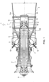
- number 1 defines a gas turbine engine comprising a compressor 2, a combustor assembly 3, a turbine 5, an exhaust gas housing 7 and an axial exhaust diffuser 8, all extending about a longitudinal axis, which is indicated by A in figure 2 .
- the diffuser may be a radial diffuser.
- the compressor 2 feeds the first combustor assembly 3 with a flow of compressed air drawn from outside.
- the first combustor assembly 3 comprises an annular combustion chamber 9 and a plurality of burners 10 circumferentially distributed about the longitudinal axis A.
- the combustor assembly could be of a different type, for example a silos combustor, a can or can-annular combustor with single or sequential stages.
- the turbine 5 receives and expands a flow of hot gas from the combustor assembly 3 to extract mechanical work, which is transferred to an external user, typically an electric generator, here not shown.
- the hot gas is then conveyed through the exhaust gas housing 7 and the exhaust diffuser 8.
- the exhaust gas housing 7 and the exhaust diffuser 8 extend along the longitudinal axis A immediately downstream of the turbine 5.
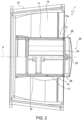
- the exhaust gas housing 7 comprises an exhaust hub 11 and an outer casing 12, that respectively define an inner boundary and an outer boundary of a portion of an exhaust flow path. Struts 14 connect the exhaust hub 11 to the outer casing 12.
- the exhaust hub 11 comprises a bearing casing 15 and a cylindrical casing 16 arranged concentrically around the bearing casing 15 (see the enlarged detail of figure 4 ).
- An annular gap 17 is defined between the bearing casing 15 and the cylindrical casing 16.
- the bearing casing 15 accommodates rear bearings 18 of a rotor 100 (not shown in figure 2 ; see figure 1 ) of the gas turbine engine 1.
- the bearing casing 15 is closed by an axially inner cover 19 at a rear end 11a of the exhaust hub 11.
- the cylindrical casing 16 defines the inner boundary of the flow path in the exhaust gas housing 7.
- the rear end 11a of the exhaust hub 11 is also sealingly closed by a hub cover assembly 20, which comprises an adapter ring 21, a spacer ring structure 22 and an external cover 25.
- a hub cover assembly 20 which comprises an adapter ring 21, a spacer ring structure 22 and an external cover 25.
- the adapter ring 21 and the spacer ring structure 22 are formed of respective separable halves, which join one another at a split plane of the gas turbine engine 1.
- the adapter ring 21 is coaxially fitted to the rear end 11a of the exhaust hub 11 and is removably connectable to the spacer ring structure 22. More precisely, the adapter ring 21 has a radial flange 26 for connection to the spacer structure 22 and a circular coupling edge 27 extending axially from the flange 26 in a direction opposite to the spacer ring structure 22. A diameter of the circular coupling edge 27 is selected to allow insertion of the circular coupling edge 27 into the annular gap 17.
- the adapter ring may be welded to the rear end 11a of the exhaust hub 11, specifically to the cylindrical casing 16.
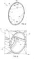
- the adapter ring 21 also comprises a plurality of wedges 30 circumferentially arranged at a same distance from a center of the adapter ring 21.
- the wedges 30 project axially from the circumferential coupling edge 27 in a direction opposite to the spacer ring structure 22 and have respective radially outer faces 30a inclined inwards in a direction away from the adapter ring 22 (in use, toward the rear end 11a of the exhaust hub 11).
- some of the wedges 30, for example two upper and two lower wedges 30, comprise respective feet 30b extending radially inwards.
- the wedges 30 equipped with feet 30b carry the mechanical load of the adapter ring 21, while the other wedges 30 may provide a centering function only and help fitting the adapter ring 21 into the gap 17.
- the different wedge or all or none of the wedges may have feet.
- the spacer ring structure 22 has a first axial end removably and sealingly connectable to the adapter ring 21, whereas a second axial end is closed by the external cover 25.
- the spacer ring structure 22 and the external cover 25 sealingly delimit a cylindrical chamber 28 laterally and axially on one side.
- the chamber 28 is axially delimited by the rear end 11a of the exhaust hub 11 on the opposite side.
- the spacer ring structure 22 and the chamber 28 need not be cylindrical or circular.
- the spacer ring structure may have oval shape or frustoconical shape, either right or oblique.
- the chamber, as it is laterally defined by the spacer ring structure, will have the same shape.
- the external cover 25 may not be coaxial with the rear end 11a of the exhaust hub 11 and the adapter ring 21.
- the external cover 25 is not coaxial.
- the spacer ring structure 22 comprises a ring shell 31, a coupling ring 32 at the first axial end and a cover ring 33 at the second axial end.
- the ring shell 31 axially extends from the first axial end to the second axial end and laterally delimits the chamber 28.
- the coupling ring 32 and the cover ring 33 may be formed monolithically with the ring shell 31; as an alternative the coupling ring 32 and the cover ring 33 may be formed as separate components and subsequently welded to opposite ends of the ring shell 31.
- the coupling ring 32 is removably connected to the adapter ring 21, e.g. by bolts 35. The connection also ensures that the chamber 28 is sealed and ingestion of hot gas is prevented.
- the coupling ring 32 extends radially inwards from the ring shell 31.
- the external cover 25 is secured to the cover ring 33 by bolts 37.
- the hub cover assembly 20 may be natively included in the gas turbine engine 1 or may be subsequently applied to the rear end 11a of the exhaust hub 11.
- the rear end 11a of the exhaust hub 11 may be prepared by forming longitudinal cuts 40 in the cylindrical casing 16.
- the longitudinal cuts 40 extend to the rear edge of the cylindrical casing and define axial tabs 41. Preparation is not strictly necessary and is particularly advantageous in case the rear end 11a of the exhaust hub 11 is severely deformed because of thermal and mechanical stress during use. If the shape of the rear end 11a has not substantially changed, the preparation may be omitted.
- the adapter ring 21 is then coaxially fitted to the rear end 11a of the exhaust hub 11 around the inner cover 19. Specifically, the circular coupling edge 27 and the wedges 30 of the adapter ring 21 are inserted in the gap 17 between the bearing casing 15 and the cylindrical casing 16. Axial tabs 41, if present, help insertion of the wedges 30 and of the circular coupling edge 27. In turn, the adapter ring 21, once fitted to the rear end 11a of the exhaust hub 11 helps restore its original circular shape, especially for the cylindrical casing 16.
- the adapter ring 21 is then welded to the cylindrical casing 16 through a welding cord, not shown.
- the coupling ring 32 at the first axial of the spacer ring structure 22 is removably and sealingly connected to the adapter ring 21 and the external cover 25 is applied to the second axial end of the spacer ring structure 22, thus forming the cylindrical chamber 28 at the rear end of the exhaust hub on a second side.
Landscapes
- Engineering & Computer Science (AREA)
- Mechanical Engineering (AREA)
- General Engineering & Computer Science (AREA)
- Chemical & Material Sciences (AREA)
- Combustion & Propulsion (AREA)
- Turbine Rotor Nozzle Sealing (AREA)
Claims (14)
- Nabenabdeckungs-Anordnung für ein Abgasgehäuse einer Hochleistungs-Gasturbinenmaschine, umfassend:einen Adapterring (21), der dazu konfiguriert ist, koaxial an einem hinteren Ende (11a) einer Abgasnabe (11) einer Hochleistungs-Gasturbinenmaschine angebracht zu werden;eine Abstandsringstruktur (22), die ein erstes axiales Ende aufweist, das abnehmbar und abdichtend mit dem Adapterring (21) verbindbar ist; undeine äußere Abdeckung (25), die an einem zweiten axialen Ende der Abstandsringstruktur (22) angebracht ist, wobei die Abstandsringstruktur (22) und die äußere Abdeckung (25) eine Kammer (28) lateral und axial auf einer Seite abdichtend begrenzen;dadurch gekennzeichnet, dass der Adapterring (21) mehrere Keile (30) umfasst, die in gleichem Abstand von einer Mitte des Adapterrings (21) angeordnet sind und axial in einer Richtung entgegengesetzt zu der Abstandsringstruktur (22) hervorstehen.
- Nabenabdeckungs-Anordnung nach Anspruch 1, wobei wenigstens einige der Keile (30) entsprechende Füße (30b) aufweisen, die sich radial nach innen erstrecken, wobei die Keile (30) vorzugsweise entsprechende radial äußere Flächen (30a) aufweisen, die von dem Adapterring (21) weg nach innen geneigt sind.
- Nabenabdeckungs-Anordnung nach einem der vorangehenden Ansprüche, wobei der Adapterring (21) einen Flansch (26) und eine kreisförmige Kupplungskante (27) umfasst, die sich axial von dem Flansch (26) in einer Richtung entgegengesetzt zu der Abstandsringstruktur (22) erstreckt.
- Nabenabdeckungs-Anordnung nach einem der vorangehenden Ansprüche, wobei die Abstandsringstruktur (22) umfasst:eine Ringhülse (31), die sich von dem ersten axialen Ende zu dem zweiten axialen Ende axial erstreckt;einen Kupplungsring (32) an dem ersten axialen Ende, wobei der Kupplungsring (32) abnehmbar und abdichtend mit dem Adapterring (21) verbindbar ist; undeinen Abdeckring (33) an dem zweiten axialen Ende, wobei die äußere Abdeckung (25) an dem Abdeckring (32) befestigt ist.
- Nabenabdeckungs-Anordnung nach Anspruch 4, wobei sich der Kupplungsring (32) von der Ringhülse (31) radial nach innen erstreckt.
- Nabenabdeckungs-Anordnung nach einem der vorangehenden Ansprüche, wobei der Adapterring (21) und die Abstandsringstruktur (22) aus entsprechenden trennbaren Hälften gebildet sind.
- Hochleistungs-Gasturbinenmaschine, die eine sich entlang einer Achse (A) erstreckende Abgasnabe (11) und eine Nabenabdeckungs-Anordnung (20) nach einem der vorangehenden Ansprüche, die ein hinteres Ende (11a) der Abgasnabe (11) abdichtend verschließt, umfasst.
- Hochleistungs-Gasturbinenmaschine nach Anspruch 7, wobei die Abgasnabe (11) eine innere Abdeckung (19) umfasst und der Adapterring (21) koaxial an dem hinteren Ende (11a) einer Abgasnabe (11) um die innere Abdeckung (19) herum angebracht ist.
- Hochleistungs-Gasturbinenmaschine nach Anspruch 7 oder 8, wobei die Abgasnabe (11) ein von der inneren Abdeckung (19) verschlossenes Lagergehäuse (15) und ein konzentrisch um das Lagergehäuse (15) angeordnetes zylindrisches Gehäuse (16) mit einem dazwischen liegenden Spalt (17) umfasst.
- Hochleistungs-Gasturbinenmaschine nach Anspruch 9, wobei die Keile (30) des Adapterrings (21) in den Spalt (17) eingesetzt sind und der Adapterring (21) vorzugsweise an das zylindrische Gehäuse (16) geschweißt ist.
- Hochleistungs-Gasturbinenmaschine nach einem der Ansprüche 7 bis 10, die ein Abgasgehäuse (7) umfasst, wobei:das Lagergehäuse (15) und das zylindrische Gehäuse (16) Teil des Abgasgehäuses (7) sind;das Abgasgehäuse (7) ferner ein äußeres Gehäuse (12) umfasst;das zylindrische Gehäuse (16) und das äußere Gehäuse (12) eine innere Begrenzung bzw. eine äußere Begrenzung eines Abgasströmungspfades in dem Abgasgehäuse (7) definieren; unddas Lagergehäuse (15) und das zylindrische Gehäuse (16) mit dem äußeren Gehäuse (12) durch Streben verbunden sind.
- Verfahren zur Nachrüstung einer Hochleistungs-Gasturbinenmaschine, die eine Abgasnabe (11) umfasst, die sich entlang einer Achse (A) erstreckt, wobei das Verfahren umfasst:koaxiales Anbringen eines Adapterrings (21) an einem hinteren Ende (115) der Abgasnabe (11);abnehmbares und dichtendes Verbinden eines ersten axialen Endes einer Abstandsringstruktur (22) mit dem Adapterring (21); undAnbringen einer äußeren Abdeckung (25) an einem zweiten axialen Ende der Abstandsringstruktur (22), wobei die Abstandsringstruktur (22) und die äußere Abdeckung (25) eine zylindrische Kammer (28) lateral und axial an einer ersten Seite abdichtend begrenzen, wobei die Kammer (28) durch das hintere Ende (11a) der Abgasnabe (11) an einer zweiten Seite axial begrenzt ist;dadurch gekennzeichnet, dass die Abgasnabe (11) ein Lagergehäuse (15), das durch die innere Abdeckung (19) verschlossen ist, und ein zylindrisches Gehäuse (16), das konzentrisch um das Lagergehäuse (15) angeordnet ist, mit einem Spalt (17) dazwischen umfasst, wobei der Adapterring (21) mehrere Keile (30) umfasst, die in einem gleichen Abstand von einer Mitte des Adapterrings (21) angeordnet sind und axial in einer Richtung entgegengesetzt zu der Abstandsringstruktur (22) hervorstehen; und wobei das koaxiale Anbringen des Adapterrings (21) das Einsetzen der Keile (30) des Adapterrings (21) in den Spalt (17) umfasst.
- Verfahren nach Anspruch 12, wobei das koaxiale Anbringen des Adapterrings (21) ein Schweißen des Adapterrings (21) an das zylindrische Gehäuse (16) umfasst.
- Verfahren nach Anspruch 12 oder 13, das die Ausbildung von Längsschnitten (40) in dem zylindrischen Gehäuse (16) umfasst, wobei sich die Längsschnitte (40) bis zu einer hinteren Kante des zylindrischen Gehäuses (16) erstrecken und axiale Laschen (41) definieren.
Priority Applications (2)
| Application Number | Priority Date | Filing Date | Title |
|---|---|---|---|
| EP21425055.7A EP4177445B1 (de) | 2021-11-05 | 2021-11-05 | Nabenabdeckungsanordnung für ein abgasgehäuse einer hochleistungsgasturbine, hochleistungsgasturbine und verfahren zum nachrüsten einer hochleistungsgasturbine |
| CN202211373490.0A CN116085113A (zh) | 2021-11-05 | 2022-11-04 | 燃气涡轮发动机及其排气气体外壳的毂盖组件和改装方法 |
Applications Claiming Priority (1)
| Application Number | Priority Date | Filing Date | Title |
|---|---|---|---|
| EP21425055.7A EP4177445B1 (de) | 2021-11-05 | 2021-11-05 | Nabenabdeckungsanordnung für ein abgasgehäuse einer hochleistungsgasturbine, hochleistungsgasturbine und verfahren zum nachrüsten einer hochleistungsgasturbine |
Publications (2)
| Publication Number | Publication Date |
|---|---|
| EP4177445A1 EP4177445A1 (de) | 2023-05-10 |
| EP4177445B1 true EP4177445B1 (de) | 2025-04-02 |
Family
ID=79231134
Family Applications (1)
| Application Number | Title | Priority Date | Filing Date |
|---|---|---|---|
| EP21425055.7A Active EP4177445B1 (de) | 2021-11-05 | 2021-11-05 | Nabenabdeckungsanordnung für ein abgasgehäuse einer hochleistungsgasturbine, hochleistungsgasturbine und verfahren zum nachrüsten einer hochleistungsgasturbine |
Country Status (2)
| Country | Link |
|---|---|
| EP (1) | EP4177445B1 (de) |
| CN (1) | CN116085113A (de) |
Family Cites Families (5)
| Publication number | Priority date | Publication date | Assignee | Title |
|---|---|---|---|---|
| US20130195647A1 (en) * | 2012-01-31 | 2013-08-01 | Marc J. Muldoon | Gas turbine engine bearing arrangement including aft bearing hub geometry |
| US9540956B2 (en) * | 2013-11-22 | 2017-01-10 | Siemens Energy, Inc. | Industrial gas turbine exhaust system with modular struts and collars |
| EP3155233B1 (de) * | 2014-06-10 | 2019-01-02 | Siemens Energy, Inc. | Gasturbinenmotor mit rotorzentrierungs- und -kühlsystem in einem abgasdiffusor |
| KR101914870B1 (ko) * | 2017-06-28 | 2018-12-28 | 두산중공업 주식회사 | 가스터빈의 분해 및 조립방법과 이에 의해 조립된 가스터빈 |
| US10953501B2 (en) * | 2018-07-25 | 2021-03-23 | Raytheon Technologies Corporation | Method of removing bearing compartment |
-
2021
- 2021-11-05 EP EP21425055.7A patent/EP4177445B1/de active Active
-
2022
- 2022-11-04 CN CN202211373490.0A patent/CN116085113A/zh active Pending
Also Published As
| Publication number | Publication date |
|---|---|
| EP4177445A1 (de) | 2023-05-10 |
| CN116085113A (zh) | 2023-05-09 |
Similar Documents
| Publication | Publication Date | Title |
|---|---|---|
| US8347500B2 (en) | Method of assembly and disassembly of a gas turbine mid turbine frame | |
| CA2672096C (en) | Fabricated itd-strut and vane ring for gas turbine engine | |
| US8500392B2 (en) | Sealing for vane segments | |
| US10132197B2 (en) | Shroud assembly and shroud for gas turbine engine | |
| US10301960B2 (en) | Shroud assembly for gas turbine engine | |
| EP2835503B1 (de) | Integrierte Streben- und Schaufelanordnungen | |
| US7237388B2 (en) | Assembly comprising a gas turbine combustion chamber integrated with a high pressure turbine nozzle | |
| US8561410B2 (en) | Outlet guide vane structure | |
| EP1247944B1 (de) | Gasturbinengehäuse | |
| US5605438A (en) | Casing distortion control for rotating machinery | |
| EP1217169B1 (de) | Verschraubung für Rotorscheiben | |
| US7237387B2 (en) | Mounting a high pressure turbine nozzle in leaktight manner to one end of a combustion chamber in a gas turbine | |
| US4503668A (en) | Strutless diffuser for gas turbine engine | |
| EP2851523A1 (de) | Mittleres Turbinenrahmensystem für Gasturbinenmotor | |
| US9528441B2 (en) | Aircraft turbofan comprising an intermediate ring with simplified downstream support | |
| EP4177445B1 (de) | Nabenabdeckungsanordnung für ein abgasgehäuse einer hochleistungsgasturbine, hochleistungsgasturbine und verfahren zum nachrüsten einer hochleistungsgasturbine | |
| EP3854995B1 (de) | Luftdichtungsanordnung | |
| EP4198270B1 (de) | Abgasgehäuse für einen hochleistungsgasturbinenmotor, hochleistungsgasturbinenmotor und verfahren zum nachrüsten einer hochleistungsgasturbine | |
| US12320275B2 (en) | Stator vane assembly for an aircraft turbine engine compressor |
Legal Events
| Date | Code | Title | Description |
|---|---|---|---|
| PUAI | Public reference made under article 153(3) epc to a published international application that has entered the european phase |
Free format text: ORIGINAL CODE: 0009012 |
|
| STAA | Information on the status of an ep patent application or granted ep patent |
Free format text: STATUS: THE APPLICATION HAS BEEN PUBLISHED |
|
| AK | Designated contracting states |
Kind code of ref document: A1 Designated state(s): AL AT BE BG CH CY CZ DE DK EE ES FI FR GB GR HR HU IE IS IT LI LT LU LV MC MK MT NL NO PL PT RO RS SE SI SK SM TR |
|
| STAA | Information on the status of an ep patent application or granted ep patent |
Free format text: STATUS: REQUEST FOR EXAMINATION WAS MADE |
|
| 17P | Request for examination filed |
Effective date: 20231106 |
|
| RBV | Designated contracting states (corrected) |
Designated state(s): AL AT BE BG CH CY CZ DE DK EE ES FI FR GB GR HR HU IE IS IT LI LT LU LV MC MK MT NL NO PL PT RO RS SE SI SK SM TR |
|
| P01 | Opt-out of the competence of the unified patent court (upc) registered |
Effective date: 20240430 |
|
| RIC1 | Information provided on ipc code assigned before grant |
Ipc: F01D 25/30 20060101AFI20241001BHEP |
|
| GRAP | Despatch of communication of intention to grant a patent |
Free format text: ORIGINAL CODE: EPIDOSNIGR1 |
|
| STAA | Information on the status of an ep patent application or granted ep patent |
Free format text: STATUS: GRANT OF PATENT IS INTENDED |
|
| INTG | Intention to grant announced |
Effective date: 20241108 |
|
| GRAS | Grant fee paid |
Free format text: ORIGINAL CODE: EPIDOSNIGR3 |
|
| GRAA | (expected) grant |
Free format text: ORIGINAL CODE: 0009210 |
|
| STAA | Information on the status of an ep patent application or granted ep patent |
Free format text: STATUS: THE PATENT HAS BEEN GRANTED |
|
| AK | Designated contracting states |
Kind code of ref document: B1 Designated state(s): AL AT BE BG CH CY CZ DE DK EE ES FI FR GB GR HR HU IE IS IT LI LT LU LV MC MK MT NL NO PL PT RO RS SE SI SK SM TR |
|
| REG | Reference to a national code |
Ref country code: GB Ref legal event code: FG4D |
|
| REG | Reference to a national code |
Ref country code: CH Ref legal event code: EP |
|
| REG | Reference to a national code |
Ref country code: IE Ref legal event code: FG4D |
|
| REG | Reference to a national code |
Ref country code: DE Ref legal event code: R096 Ref document number: 602021028476 Country of ref document: DE |
|
| REG | Reference to a national code |
Ref country code: NL Ref legal event code: MP Effective date: 20250402 |
|
| PG25 | Lapsed in a contracting state [announced via postgrant information from national office to epo] |
Ref country code: NL Free format text: LAPSE BECAUSE OF FAILURE TO SUBMIT A TRANSLATION OF THE DESCRIPTION OR TO PAY THE FEE WITHIN THE PRESCRIBED TIME-LIMIT Effective date: 20250402 |
|
| REG | Reference to a national code |
Ref country code: AT Ref legal event code: MK05 Ref document number: 1781446 Country of ref document: AT Kind code of ref document: T Effective date: 20250402 |
|
| PG25 | Lapsed in a contracting state [announced via postgrant information from national office to epo] |
Ref country code: ES Free format text: LAPSE BECAUSE OF FAILURE TO SUBMIT A TRANSLATION OF THE DESCRIPTION OR TO PAY THE FEE WITHIN THE PRESCRIBED TIME-LIMIT Effective date: 20250402 Ref country code: FI Free format text: LAPSE BECAUSE OF FAILURE TO SUBMIT A TRANSLATION OF THE DESCRIPTION OR TO PAY THE FEE WITHIN THE PRESCRIBED TIME-LIMIT Effective date: 20250402 Ref country code: PT Free format text: LAPSE BECAUSE OF FAILURE TO SUBMIT A TRANSLATION OF THE DESCRIPTION OR TO PAY THE FEE WITHIN THE PRESCRIBED TIME-LIMIT Effective date: 20250804 |
|
| REG | Reference to a national code |
Ref country code: LT Ref legal event code: MG9D |
|
| PG25 | Lapsed in a contracting state [announced via postgrant information from national office to epo] |
Ref country code: GR Free format text: LAPSE BECAUSE OF FAILURE TO SUBMIT A TRANSLATION OF THE DESCRIPTION OR TO PAY THE FEE WITHIN THE PRESCRIBED TIME-LIMIT Effective date: 20250703 Ref country code: NO Free format text: LAPSE BECAUSE OF FAILURE TO SUBMIT A TRANSLATION OF THE DESCRIPTION OR TO PAY THE FEE WITHIN THE PRESCRIBED TIME-LIMIT Effective date: 20250702 |
|
| PG25 | Lapsed in a contracting state [announced via postgrant information from national office to epo] |
Ref country code: PL Free format text: LAPSE BECAUSE OF FAILURE TO SUBMIT A TRANSLATION OF THE DESCRIPTION OR TO PAY THE FEE WITHIN THE PRESCRIBED TIME-LIMIT Effective date: 20250402 |
|
| PG25 | Lapsed in a contracting state [announced via postgrant information from national office to epo] |
Ref country code: BG Free format text: LAPSE BECAUSE OF FAILURE TO SUBMIT A TRANSLATION OF THE DESCRIPTION OR TO PAY THE FEE WITHIN THE PRESCRIBED TIME-LIMIT Effective date: 20250402 |
|
| PG25 | Lapsed in a contracting state [announced via postgrant information from national office to epo] |
Ref country code: HR Free format text: LAPSE BECAUSE OF FAILURE TO SUBMIT A TRANSLATION OF THE DESCRIPTION OR TO PAY THE FEE WITHIN THE PRESCRIBED TIME-LIMIT Effective date: 20250402 |
|
| PG25 | Lapsed in a contracting state [announced via postgrant information from national office to epo] |
Ref country code: AT Free format text: LAPSE BECAUSE OF FAILURE TO SUBMIT A TRANSLATION OF THE DESCRIPTION OR TO PAY THE FEE WITHIN THE PRESCRIBED TIME-LIMIT Effective date: 20250402 |
|
| PG25 | Lapsed in a contracting state [announced via postgrant information from national office to epo] |
Ref country code: RS Free format text: LAPSE BECAUSE OF FAILURE TO SUBMIT A TRANSLATION OF THE DESCRIPTION OR TO PAY THE FEE WITHIN THE PRESCRIBED TIME-LIMIT Effective date: 20250702 |
|
| PG25 | Lapsed in a contracting state [announced via postgrant information from national office to epo] |
Ref country code: IS Free format text: LAPSE BECAUSE OF FAILURE TO SUBMIT A TRANSLATION OF THE DESCRIPTION OR TO PAY THE FEE WITHIN THE PRESCRIBED TIME-LIMIT Effective date: 20250802 |
|
| PG25 | Lapsed in a contracting state [announced via postgrant information from national office to epo] |
Ref country code: LV Free format text: LAPSE BECAUSE OF FAILURE TO SUBMIT A TRANSLATION OF THE DESCRIPTION OR TO PAY THE FEE WITHIN THE PRESCRIBED TIME-LIMIT Effective date: 20250402 |
|
| REG | Reference to a national code |
Ref country code: DE Ref legal event code: R097 Ref document number: 602021028476 Country of ref document: DE |
|
| PGFP | Annual fee paid to national office [announced via postgrant information from national office to epo] |
Ref country code: DE Payment date: 20251118 Year of fee payment: 5 |
|
| PG25 | Lapsed in a contracting state [announced via postgrant information from national office to epo] |
Ref country code: DK Free format text: LAPSE BECAUSE OF FAILURE TO SUBMIT A TRANSLATION OF THE DESCRIPTION OR TO PAY THE FEE WITHIN THE PRESCRIBED TIME-LIMIT Effective date: 20250402 Ref country code: SM Free format text: LAPSE BECAUSE OF FAILURE TO SUBMIT A TRANSLATION OF THE DESCRIPTION OR TO PAY THE FEE WITHIN THE PRESCRIBED TIME-LIMIT Effective date: 20250402 |
|
| PGFP | Annual fee paid to national office [announced via postgrant information from national office to epo] |
Ref country code: IT Payment date: 20251128 Year of fee payment: 5 |
|
| PG25 | Lapsed in a contracting state [announced via postgrant information from national office to epo] |
Ref country code: CZ Free format text: LAPSE BECAUSE OF FAILURE TO SUBMIT A TRANSLATION OF THE DESCRIPTION OR TO PAY THE FEE WITHIN THE PRESCRIBED TIME-LIMIT Effective date: 20250402 |
|
| PG25 | Lapsed in a contracting state [announced via postgrant information from national office to epo] |
Ref country code: EE Free format text: LAPSE BECAUSE OF FAILURE TO SUBMIT A TRANSLATION OF THE DESCRIPTION OR TO PAY THE FEE WITHIN THE PRESCRIBED TIME-LIMIT Effective date: 20250402 |
|
| PG25 | Lapsed in a contracting state [announced via postgrant information from national office to epo] |
Ref country code: SK Free format text: LAPSE BECAUSE OF FAILURE TO SUBMIT A TRANSLATION OF THE DESCRIPTION OR TO PAY THE FEE WITHIN THE PRESCRIBED TIME-LIMIT Effective date: 20250402 |
|
| PLBE | No opposition filed within time limit |
Free format text: ORIGINAL CODE: 0009261 |
|
| STAA | Information on the status of an ep patent application or granted ep patent |
Free format text: STATUS: NO OPPOSITION FILED WITHIN TIME LIMIT |
|
| REG | Reference to a national code |
Ref country code: CH Ref legal event code: L10 Free format text: ST27 STATUS EVENT CODE: U-0-0-L10-L00 (AS PROVIDED BY THE NATIONAL OFFICE) Effective date: 20260211 |
|
| PG25 | Lapsed in a contracting state [announced via postgrant information from national office to epo] |
Ref country code: RO Free format text: LAPSE BECAUSE OF FAILURE TO SUBMIT A TRANSLATION OF THE DESCRIPTION OR TO PAY THE FEE WITHIN THE PRESCRIBED TIME-LIMIT Effective date: 20250402 |
|
| 26N | No opposition filed |
Effective date: 20260105 |