EP4177052A1 - 3d woven space filler - Google Patents
3d woven space filler Download PDFInfo
- Publication number
- EP4177052A1 EP4177052A1 EP22205639.2A EP22205639A EP4177052A1 EP 4177052 A1 EP4177052 A1 EP 4177052A1 EP 22205639 A EP22205639 A EP 22205639A EP 4177052 A1 EP4177052 A1 EP 4177052A1
- Authority
- EP
- European Patent Office
- Prior art keywords
- porosity
- region
- insert
- volume fraction
- preform
- Prior art date
- Legal status (The legal status is an assumption and is not a legal conclusion. Google has not performed a legal analysis and makes no representation as to the accuracy of the status listed.)
- Granted
Links
Images

Classifications
-
- C—CHEMISTRY; METALLURGY
- C04—CEMENTS; CONCRETE; ARTIFICIAL STONE; CERAMICS; REFRACTORIES
- C04B—LIME, MAGNESIA; SLAG; CEMENTS; COMPOSITIONS THEREOF, e.g. MORTARS, CONCRETE OR LIKE BUILDING MATERIALS; ARTIFICIAL STONE; CERAMICS; REFRACTORIES; TREATMENT OF NATURAL STONE
- C04B35/00—Shaped ceramic products characterised by their composition; Ceramics compositions; Processing powders of inorganic compounds preparatory to the manufacturing of ceramic products
- C04B35/71—Ceramic products containing macroscopic reinforcing agents
- C04B35/78—Ceramic products containing macroscopic reinforcing agents containing non-metallic materials
- C04B35/80—Fibres, filaments, whiskers, platelets, or the like
-
- B—PERFORMING OPERATIONS; TRANSPORTING
- B32—LAYERED PRODUCTS
- B32B—LAYERED PRODUCTS, i.e. PRODUCTS BUILT-UP OF STRATA OF FLAT OR NON-FLAT, e.g. CELLULAR OR HONEYCOMB, FORM
- B32B18/00—Layered products essentially comprising ceramics, e.g. refractory products
-
- C—CHEMISTRY; METALLURGY
- C04—CEMENTS; CONCRETE; ARTIFICIAL STONE; CERAMICS; REFRACTORIES
- C04B—LIME, MAGNESIA; SLAG; CEMENTS; COMPOSITIONS THEREOF, e.g. MORTARS, CONCRETE OR LIKE BUILDING MATERIALS; ARTIFICIAL STONE; CERAMICS; REFRACTORIES; TREATMENT OF NATURAL STONE
- C04B35/00—Shaped ceramic products characterised by their composition; Ceramics compositions; Processing powders of inorganic compounds preparatory to the manufacturing of ceramic products
- C04B35/622—Forming processes; Processing powders of inorganic compounds preparatory to the manufacturing of ceramic products
- C04B35/626—Preparing or treating the powders individually or as batches ; preparing or treating macroscopic reinforcing agents for ceramic products, e.g. fibres; mechanical aspects section B
- C04B35/628—Coating the powders or the macroscopic reinforcing agents
- C04B35/62844—Coating fibres
-
- C—CHEMISTRY; METALLURGY
- C04—CEMENTS; CONCRETE; ARTIFICIAL STONE; CERAMICS; REFRACTORIES
- C04B—LIME, MAGNESIA; SLAG; CEMENTS; COMPOSITIONS THEREOF, e.g. MORTARS, CONCRETE OR LIKE BUILDING MATERIALS; ARTIFICIAL STONE; CERAMICS; REFRACTORIES; TREATMENT OF NATURAL STONE
- C04B2235/00—Aspects relating to ceramic starting mixtures or sintered ceramic products
- C04B2235/02—Composition of constituents of the starting material or of secondary phases of the final product
- C04B2235/50—Constituents or additives of the starting mixture chosen for their shape or used because of their shape or their physical appearance
- C04B2235/52—Constituents or additives characterised by their shapes
- C04B2235/5208—Fibers
- C04B2235/5216—Inorganic
- C04B2235/524—Non-oxidic, e.g. borides, carbides, silicides or nitrides
- C04B2235/5244—Silicon carbide
-
- C—CHEMISTRY; METALLURGY
- C04—CEMENTS; CONCRETE; ARTIFICIAL STONE; CERAMICS; REFRACTORIES
- C04B—LIME, MAGNESIA; SLAG; CEMENTS; COMPOSITIONS THEREOF, e.g. MORTARS, CONCRETE OR LIKE BUILDING MATERIALS; ARTIFICIAL STONE; CERAMICS; REFRACTORIES; TREATMENT OF NATURAL STONE
- C04B2235/00—Aspects relating to ceramic starting mixtures or sintered ceramic products
- C04B2235/02—Composition of constituents of the starting material or of secondary phases of the final product
- C04B2235/50—Constituents or additives of the starting mixture chosen for their shape or used because of their shape or their physical appearance
- C04B2235/52—Constituents or additives characterised by their shapes
- C04B2235/5208—Fibers
- C04B2235/5252—Fibers having a specific pre-form
-
- C—CHEMISTRY; METALLURGY
- C04—CEMENTS; CONCRETE; ARTIFICIAL STONE; CERAMICS; REFRACTORIES
- C04B—LIME, MAGNESIA; SLAG; CEMENTS; COMPOSITIONS THEREOF, e.g. MORTARS, CONCRETE OR LIKE BUILDING MATERIALS; ARTIFICIAL STONE; CERAMICS; REFRACTORIES; TREATMENT OF NATURAL STONE
- C04B2235/00—Aspects relating to ceramic starting mixtures or sintered ceramic products
- C04B2235/02—Composition of constituents of the starting material or of secondary phases of the final product
- C04B2235/50—Constituents or additives of the starting mixture chosen for their shape or used because of their shape or their physical appearance
- C04B2235/52—Constituents or additives characterised by their shapes
- C04B2235/5208—Fibers
- C04B2235/5252—Fibers having a specific pre-form
- C04B2235/5256—Two-dimensional, e.g. woven structures
-
- C—CHEMISTRY; METALLURGY
- C04—CEMENTS; CONCRETE; ARTIFICIAL STONE; CERAMICS; REFRACTORIES
- C04B—LIME, MAGNESIA; SLAG; CEMENTS; COMPOSITIONS THEREOF, e.g. MORTARS, CONCRETE OR LIKE BUILDING MATERIALS; ARTIFICIAL STONE; CERAMICS; REFRACTORIES; TREATMENT OF NATURAL STONE
- C04B2235/00—Aspects relating to ceramic starting mixtures or sintered ceramic products
- C04B2235/60—Aspects relating to the preparation, properties or mechanical treatment of green bodies or pre-forms
- C04B2235/602—Making the green bodies or pre-forms by moulding
- C04B2235/6028—Shaping around a core which is removed later
-
- C—CHEMISTRY; METALLURGY
- C04—CEMENTS; CONCRETE; ARTIFICIAL STONE; CERAMICS; REFRACTORIES
- C04B—LIME, MAGNESIA; SLAG; CEMENTS; COMPOSITIONS THEREOF, e.g. MORTARS, CONCRETE OR LIKE BUILDING MATERIALS; ARTIFICIAL STONE; CERAMICS; REFRACTORIES; TREATMENT OF NATURAL STONE
- C04B2237/00—Aspects relating to ceramic laminates or to joining of ceramic articles with other articles by heating
- C04B2237/50—Processing aspects relating to ceramic laminates or to the joining of ceramic articles with other articles by heating
- C04B2237/58—Forming a gradient in composition or in properties across the laminate or the joined articles
- C04B2237/586—Forming a gradient in composition or in properties across the laminate or the joined articles by joining layers or articles of the same composition but having different densities
-
- C—CHEMISTRY; METALLURGY
- C04—CEMENTS; CONCRETE; ARTIFICIAL STONE; CERAMICS; REFRACTORIES
- C04B—LIME, MAGNESIA; SLAG; CEMENTS; COMPOSITIONS THEREOF, e.g. MORTARS, CONCRETE OR LIKE BUILDING MATERIALS; ARTIFICIAL STONE; CERAMICS; REFRACTORIES; TREATMENT OF NATURAL STONE
- C04B2237/00—Aspects relating to ceramic laminates or to joining of ceramic articles with other articles by heating
- C04B2237/50—Processing aspects relating to ceramic laminates or to the joining of ceramic articles with other articles by heating
- C04B2237/84—Joining of a first substrate with a second substrate at least partially inside the first substrate, where the bonding area is at the inside of the first substrate, e.g. one tube inside another tube
Definitions
- the present invention relates to ceramic matrix composites and, more particularly, space filling inserts for use in ceramic matrix composite preforms.
- CMC ceramic matrix composite
- Many ceramic matrix composite (CMC) components for gas turbine engines have regions of variable wall thickness. Some of these regions are too small to form with standard ply(s) of woven cloth but too large to form using individual fiber tows. In such cases, space filling inserts can be used to build upon and prevent large voids in the body of the CMC. As with other locally-thickened regions of CMCs, these inserts can often present challenges in achieving a high and/or uniform density through the chemical vapor infiltration (CVI) process.
- CVI chemical vapor infiltration
- a ceramic fiber preform includes a plurality of ceramic fiber plies arranged to define a wall, a void adjacent the wall, and an insert positioned within the void.
- the insert includes a first region having a first porosity and a second region in physical contact with the first region and having a second porosity.
- the first region and second region are formed from a woven ceramic material, the wall has a wall porosity, and the first porosity is less than at least one of the second porosity and the wall porosity.
- a ceramic fiber preforms includes a woven ceramic insert having a first porosity and a plurality of ceramic fiber plies surrounding the insert to form an outer layer.
- the outer layer has a second porosity greater than the first porosity.
- an insert for inclusion in a void of a ceramic fiber preform includes a first region having a first porosity and a second region in physical contact with the first region and having a second porosity.
- the first region and the second region are formed from a woven ceramic material, and the first porosity is different from the second porosity.
- the inserts can be formed using a three-dimensional (3D) weaving technique to create a structure with a gradient porosity through its thickness. More specifically, two or more regions of differing porosity can be incorporated into an insert depending on factors such as its thickness and shape.
- the gradient arrangement enables a more even matrix infiltration of the insert and encompassing preform structure.
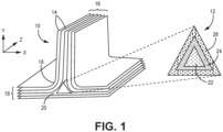
- FIG. 1 is a simplified perspective view of preform 10 with an enlarged view of insert 12.
- Preform 10 can be used to form a CMC component for use in a gas turbine engine combustor, compressor, and/or turbine section, to name a few non-limiting examples.
- Preform 10 is formed from multiple plies 14 laid up in such a manner as to form a structure with a desired shape and thickness.
- Plies 14 can be formed from braided, woven, and/or chopped ceramic fibers or tows.
- the ceramic material can be silicon carbide or another suitable ceramic material.
- plies 14 can be laid up to form walls 16 with curved regions 18. The bending of plies 14 to form curved region 18 can create a void 20 between a subset of plies 14.
- Void 20 can be too small to effectively fill with additional plies 14, and too large to fill with individual ceramic tows or tow bundles.
- insert 12 can be formed to have a shape and size generally complementary to void 20. More specifically, insert 12 can be formed to have a complementary triangular cross-sectional geometry, a thickness or width defined in one or a combination of the x and y-axes, and a length extending alone the z-axis. Generally speaking, insert 12 is sized to fill void 20 along the x, y, and z-axes.
- Insert 12 can be formed from woven ceramic fibers, as is discussed in greater detail below. As can be seen in the enlarged view, insert 12 includes regions 22, 24, and 26 in the concentrically innermost to outermost direction. Insert 12 can include just two or four regions in an alternative embodiment. Each region is associated with a different material porosity. In an exemplary embodiment, innermost (first) region 22 has a first porosity, middle (second) region 24 has a second porosity, and outermost (third) region 26 has a third porosity. The porosity gradient of insert 12 is such that first porosity ⁇ second porosity ⁇ third porosity. Material porosity can be a function of the fiber volume fraction of the woven ceramic material in each region 22, 24, and 26.
- Each of these regions can be formed to have a fiber volume fraction (i.e., the fraction of fiber volume to total volume of the insert) and a void/pore fraction (i.e., the fraction of void/pore volume to total volume of the insert) that differs from the other regions.
- fiber volume fraction and pore volume fraction are generally inversely proportional such that a region with low porosity will have a high fiber volume fraction relative to the other regions.
- the fiber volume fraction of each region will differ from the immediately adjacent region by at least 1%.
- region 22 can have a fiber volume fraction ranging from 40% to 45%
- region 24 can have a fiber volume fraction ranging from 35% to 40%
- region 26 can have a fiber volume fraction ranging from 30% to 35%.
- Walls 16 abutting void 20/insert 12 can also have a wall porosity and fiber volume fraction different from most or all of sections 22, 24, 26.
- walls 16 can have a porosity and fiber volume fraction generally equal to or slightly less than immediately adjacent region 26. More specifically, the fiber volume fraction of walls 16 can range from 32% to 40%.
- Insert 12 can be formed by 3D (i.e., Jacquard) weaving, having fiber components in three, generally orthogonal (x, y, z) axes.
- insert 12 can have warp and weft fibers (tows), but can further include z-fibers orthogonal to and crossing over layers of warp and/or weft fibers.
- the various fibers can be formed from the same ceramic (e.g., silicon carbide) material, or from combinations of different ceramics.
- polymer fibers or yarns can be included at some positions on the loom and incorporated into the insert.
- the polymer fibers can be decomposed (e.g., thermally or chemically) during subsequent processing to help locally control the fiber volume fraction/porosity of the insert, as these fugitive polymer fibers leave behind open spaces when decomposed.
- Certain embodiments can be formed such that each section 22, 24, 26 is separately woven from and joined with the other sections. More specifically, first section 22 can be woven, then second section 24 can be woven around first section 22, then third section 26 can be woven around section 24.
- material characteristics such as fiber length, shape, and/or cross-sectional area can be varied to achieve different fiber volume fractions.
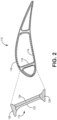
- FIG. 2 is a simplified cross-sectional view of airfoil preform 110 with an enlarged view of insert 112.
- preform 110 is formed from various plies 114, which can be substantially similar to plies 14.
- Insert 112 has an I-shaped cross-sectional geometry and is incorporated into an airfoil structural rib spanning between outer walls 116 formed by plies 114. Although not visible in FIG. 2 , insert 112 occupies a complementary void between rib walls 116 also formed by plies 114.
- insert 112 has abutting regions 122, 124, 126, and 128.
- all four regions 122, 124, 126, 128 can have different porosities.
- insert 112 can have only three regions, for example, with one on each end and one larger section (e.g., a combination of regions 122 and 124) disposed between the two ends. Other arrangements are contemplated herein.
- the fiber volume fraction of each region can be substantially similar to the ranges discussed above with respect to insert 12. That is, the fiber volume fraction of region 122 can range from 40% to 45%, region 124 can have a fiber volume fraction ranging from 35% to 40%, and regions 126 and 128 can each have a fiber volume fraction ranging from 30% to 35%. Walls 116 can have a fiber volume fraction ranging from 32% to 40%.
- insert 112 can be formed by 3D weaving. Each section can be individually woven and joined together using, for example, using a stitching technique to secure each section to the abutting section, or various adhesives can be used.
- preforms 10 and 110 can undergo matrix formation and densification using a CVI process in which plies 14, 114 and inserts 12, 112 are infiltrated by reactant vapors, and a gaseous precursor deposits on the ceramic fibers.
- the matrix material can be a silicon carbide or other suitable ceramic material. Densification is carried out until the resulting CMC has reached the desired residual porosity.
- the gradient arrangement of inserts 12, 112 with respect to the abutting walls 16, 116 allows for a more even distribution of matrix precursor material within preforms 10, 110.
- the regions can be arranged in any desired manner based on the expected direction of flow of the gaseous precursor in the reactor, for example, with regions more exposed to the gaseous precursor being more porous than those shielded by other preform structures.
- the porosity/fiber volume fraction gradient of insert 12, for example can produce a uniform density to the final workpiece (i.e., post-densification) by facilitating infiltration through higher porosity regions and providing higher fiber volume fraction in regions more difficult to infiltrate.
- the porosity gradient of any insert e.g., 112 can be selected to produce desired densities in different portions of the completed workpiece by providing locally increased preform density or locally enhanced infiltration via increased porosity.
- FIG. 3 is simplified cross-sectional view of preform 210 having T-shaped core insert 212 surrounded by plies 214.
- core insert 212 can serve as a scaffolding on which to lay up plies 214.
- Core insert 212 can further make up the majority (greater than 50%) of the total volume of preform 210.
- Plies 214 form a wall or outer layer 216 surrounding core insert 212.
- Plies 214 are substantially similar in composition to plies 14 and 114.
- Core insert 212 is similar to inserts 12 and 112 in composition and method of formation.
- core insert 212 can have a generally uniform porosity while a porosity gradient is created across preform 210 by making core insert 212 less porous (having a higher fiber volume fraction) than surrounding outer layer 216.
- core insert 212 can be formed to have regions of varying porosity.
- Preform 210 can undergo matrix formation in the same manner as preforms 10 and 110 such that a porosity gradient permits more even matrix distribution.
- insert shapes such as rectangular, circular, elliptical, "U,” and “V” can alternatively and/or additionally be formed for incorporation into the disclosed preforms without departing from the scope of the invention.
- a CMC component formed with the disclosed inserts can be incorporated into aerospace, maritime, or industrial equipment, to name a few, non-limiting examples.
- a ceramic fiber preform includes a plurality of ceramic fiber plies arranged to define a wall, a void adjacent the wall, and an insert positioned within the void.
- the insert includes a first region having a first porosity and a second region in physical contact with the first region and having a second porosity.
- the first region and second region are formed from a woven ceramic material, the wall has a wall porosity, and the first porosity is less than at least one of the second porosity and the wall porosity.
- the preform of the preceding paragraph can optionally include, additionally and/or alternatively, any one or more of the following features, configurations and/or additional components:
- the ceramic fiber plies and the woven ceramic material can be formed from silicon carbide.
- the insert can further include a third region in physical contact with at least one of the first or second region and having a third porosity.
- the first porosity can be less than the second porosity, and the second porosity can be less than the third porosity and the wall porosity.
- the first region can have a first fiber volume fraction
- the second region can have a second fiber volume fraction
- the third region can have a third fiber volume fraction
- the wall can have a wall fiber volume fraction
- the first fiber volume fraction can be greater than the second fiber volume fraction, and the second fiber volume fraction can be greater than the third fiber volume fraction and the wall fiber volume fraction.
- the insert can have a one of a triangular cross-sectional shape and an "I" cross-sectional shape.
- a gas turbine engine component can include any of the above preforms and a ceramic matrix deposited onto and within the preform.
- a ceramic fiber preforms includes a woven ceramic insert having a first porosity and a plurality of ceramic fiber plies surrounding the insert to form an outer layer.
- the outer layer has a second porosity greater than the first porosity.
- the insert can have a "T" cross-sectional shape.
- the insert can be 50% or more of the total volume of the preform.
- An insert for inclusion in a void of a ceramic fiber preform includes a first region having a first porosity and a second region in physical contact with the first region and having a second porosity.
- the first region and the second region are formed from a woven ceramic material, and the first porosity is different from the second porosity.
- the woven ceramic material can include tows of silicon carbide.
- any of the above inserts can further include woven polymer fibers.
- any of the above inserts can further include a third region in physical contact with at least one of the first or second region and having a third porosity, and the third region can be formed from the woven ceramic material.
- the first region can be positioned concentrically within the second region, the second region can be positioned concentrically within the third region, the first porosity can be less than the second porosity, and the second porosity can be less than the third porosity.
- the first region can have a first fiber volume fraction
- the second region can have a second fiber volume fraction less than the first fiber volume fraction
- the third region can have a third fiber volume fraction less than the second fiber volume fraction
- Any of the above inserts can have a triangular cross-sectional shape.
- any of the above inserts can further include a fourth region in physical contact with at least one of the first, second, or third regions and having a fourth porosity.
- the fourth region can be formed from the woven ceramic material, and the fourth porosity can be greater than at least one of the first porosity, the second porosity, and the third porosity.
- any of the above inserts can have a "I" cross-sectional shape.
Landscapes
- Chemical & Material Sciences (AREA)
- Engineering & Computer Science (AREA)
- Ceramic Engineering (AREA)
- Manufacturing & Machinery (AREA)
- Materials Engineering (AREA)
- Structural Engineering (AREA)
- Organic Chemistry (AREA)
- Chemical Kinetics & Catalysis (AREA)
- Inorganic Chemistry (AREA)
- Turbine Rotor Nozzle Sealing (AREA)
Abstract
Description
- The present invention relates to ceramic matrix composites and, more particularly, space filling inserts for use in ceramic matrix composite preforms.
- Many ceramic matrix composite (CMC) components for gas turbine engines have regions of variable wall thickness. Some of these regions are too small to form with standard ply(s) of woven cloth but too large to form using individual fiber tows. In such cases, space filling inserts can be used to build upon and prevent large voids in the body of the CMC. As with other locally-thickened regions of CMCs, these inserts can often present challenges in achieving a high and/or uniform density through the chemical vapor infiltration (CVI) process.
- From one aspect, there is provided a ceramic fiber preform includes a plurality of ceramic fiber plies arranged to define a wall, a void adjacent the wall, and an insert positioned within the void. The insert includes a first region having a first porosity and a second region in physical contact with the first region and having a second porosity. The first region and second region are formed from a woven ceramic material, the wall has a wall porosity, and the first porosity is less than at least one of the second porosity and the wall porosity.
- There is also provided a ceramic fiber preforms includes a woven ceramic insert having a first porosity and a plurality of ceramic fiber plies surrounding the insert to form an outer layer. The outer layer has a second porosity greater than the first porosity.
- There is also provided an insert for inclusion in a void of a ceramic fiber preform includes a first region having a first porosity and a second region in physical contact with the first region and having a second porosity. The first region and the second region are formed from a woven ceramic material, and the first porosity is different from the second porosity.
- Features of embodiments are set forth in the dependent claims.
-
-
FIG. 1 is a simplified perspective view of a preform structure with a triangular insert shown in close-up. -
FIG. 2 is simplified cross-sectional view of an airfoil preform with an I-shaped insert shown in close-up. -
FIG. 3 is a simplified cross-sectional view of a preform structure with a T-shaped core insert. - While the above-identified figures set forth one or more embodiments of the present disclosure, other embodiments are also contemplated, as noted in the discussion. In all cases, this disclosure presents the invention by way of representation and not limitation. It should be understood that numerous other modifications and embodiments can be devised by those skilled in the art, which fall within the scope and spirit of the principles of the invention. The figures may not be drawn to scale, and applications and embodiments of the present invention may include features and components not specifically shown in the drawings.
- This disclosure presents various space filling inserts, sometimes referred to as "noodles," for incorporation into a CMC preform. The inserts can be formed using a three-dimensional (3D) weaving technique to create a structure with a gradient porosity through its thickness. More specifically, two or more regions of differing porosity can be incorporated into an insert depending on factors such as its thickness and shape. The gradient arrangement enables a more even matrix infiltration of the insert and encompassing preform structure.
-
FIG. 1 is a simplified perspective view ofpreform 10 with an enlarged view ofinsert 12. Preform 10 can be used to form a CMC component for use in a gas turbine engine combustor, compressor, and/or turbine section, to name a few non-limiting examples.Preform 10 is formed frommultiple plies 14 laid up in such a manner as to form a structure with a desired shape and thickness.Plies 14 can be formed from braided, woven, and/or chopped ceramic fibers or tows. The ceramic material can be silicon carbide or another suitable ceramic material. As shown inFIG. 1 ,plies 14 can be laid up to formwalls 16 withcurved regions 18. The bending ofplies 14 to formcurved region 18 can create avoid 20 between a subset ofplies 14.Void 20 can be too small to effectively fill withadditional plies 14, and too large to fill with individual ceramic tows or tow bundles. Thus,insert 12 can be formed to have a shape and size generally complementary tovoid 20. More specifically,insert 12 can be formed to have a complementary triangular cross-sectional geometry, a thickness or width defined in one or a combination of the x and y-axes, and a length extending alone the z-axis. Generally speaking,insert 12 is sized to fillvoid 20 along the x, y, and z-axes. - Insert 12 can be formed from woven ceramic fibers, as is discussed in greater detail below. As can be seen in the enlarged view,
insert 12 includesregions region 22 has a first porosity, middle (second)region 24 has a second porosity, and outermost (third)region 26 has a third porosity. The porosity gradient ofinsert 12 is such that first porosity < second porosity < third porosity. Material porosity can be a function of the fiber volume fraction of the woven ceramic material in eachregion region 22 can have a fiber volume fraction ranging from 40% to 45%,region 24 can have a fiber volume fraction ranging from 35% to 40%, andregion 26 can have a fiber volume fraction ranging from 30% to 35%.Walls 16 abuttingvoid 20/insert 12 can also have a wall porosity and fiber volume fraction different from most or all ofsections walls 16 can have a porosity and fiber volume fraction generally equal to or slightly less than immediatelyadjacent region 26. More specifically, the fiber volume fraction ofwalls 16 can range from 32% to 40%. - Insert 12 can be formed by 3D (i.e., Jacquard) weaving, having fiber components in three, generally orthogonal (x, y, z) axes. As with two-dimensional (2D) woven structures (e.g., plies 14),
insert 12 can have warp and weft fibers (tows), but can further include z-fibers orthogonal to and crossing over layers of warp and/or weft fibers. The various fibers can be formed from the same ceramic (e.g., silicon carbide) material, or from combinations of different ceramics. In an alternative embodiment, polymer fibers or yarns can be included at some positions on the loom and incorporated into the insert. In such an embodiment, the polymer fibers can be decomposed (e.g., thermally or chemically) during subsequent processing to help locally control the fiber volume fraction/porosity of the insert, as these fugitive polymer fibers leave behind open spaces when decomposed. Certain embodiments can be formed such that eachsection first section 22 can be woven, thensecond section 24 can be woven aroundfirst section 22, thenthird section 26 can be woven aroundsection 24. In order to achieve the porosity gradient acrosssections -
FIG. 2 is a simplified cross-sectional view ofairfoil preform 110 with an enlarged view ofinsert 112. Likepreform 10,preform 110 is formed fromvarious plies 114, which can be substantially similar to plies 14.Insert 112 has an I-shaped cross-sectional geometry and is incorporated into an airfoil structural rib spanning betweenouter walls 116 formed byplies 114. Although not visible inFIG. 2 , insert 112 occupies a complementary void betweenrib walls 116 also formed byplies 114. - Instead of multiple concentric regions, insert 112 has abutting
regions first region 122 <second region 124 <third region 126 =fourth region 128. That is, the distal ends (regions 126 and 128) ofinsert 112 can have equal porosities. In an alternative embodiment, all fourregions regions 122 and 124) disposed between the two ends. Other arrangements are contemplated herein. The fiber volume fraction of each region can be substantially similar to the ranges discussed above with respect to insert 12. That is, the fiber volume fraction ofregion 122 can range from 40% to 45%,region 124 can have a fiber volume fraction ranging from 35% to 40%, andregions Walls 116 can have a fiber volume fraction ranging from 32% to 40%. Likeinsert 12, insert 112 can be formed by 3D weaving. Each section can be individually woven and joined together using, for example, using a stitching technique to secure each section to the abutting section, or various adhesives can be used. - Referring now to both
FIGS. 1 and2 , preforms 10 and 110 can undergo matrix formation and densification using a CVI process in which plies 14, 114 and inserts 12, 112 are infiltrated by reactant vapors, and a gaseous precursor deposits on the ceramic fibers. The matrix material can be a silicon carbide or other suitable ceramic material. Densification is carried out until the resulting CMC has reached the desired residual porosity. The gradient arrangement ofinserts walls preforms inserts insert 12, for example, can produce a uniform density to the final workpiece (i.e., post-densification) by facilitating infiltration through higher porosity regions and providing higher fiber volume fraction in regions more difficult to infiltrate. More generally, the porosity gradient of any insert (e.g., 112) can be selected to produce desired densities in different portions of the completed workpiece by providing locally increased preform density or locally enhanced infiltration via increased porosity. -
FIG. 3 is simplified cross-sectional view ofpreform 210 having T-shapedcore insert 212 surrounded byplies 214. Instead of being inserted into a void created by the lay-up ofplies 214,core insert 212 can serve as a scaffolding on which to lay up plies 214.Core insert 212 can further make up the majority (greater than 50%) of the total volume ofpreform 210.Plies 214 form a wall orouter layer 216 surroundingcore insert 212.Plies 214 are substantially similar in composition to plies 14 and 114.Core insert 212 is similar toinserts core insert 212 can have a generally uniform porosity while a porosity gradient is created acrosspreform 210 by making core insert 212 less porous (having a higher fiber volume fraction) than surroundingouter layer 216. In an alternative embodiment,core insert 212 can be formed to have regions of varying porosity. Preform 210 can undergo matrix formation in the same manner as preforms 10 and 110 such that a porosity gradient permits more even matrix distribution. - It should be understood that various other insert shapes, such as rectangular, circular, elliptical, "U," and "V" can alternatively and/or additionally be formed for incorporation into the disclosed preforms without departing from the scope of the invention. A CMC component formed with the disclosed inserts can be incorporated into aerospace, maritime, or industrial equipment, to name a few, non-limiting examples.
- The following are non-exclusive descriptions of possible embodiments of the present invention.
- A ceramic fiber preform includes a plurality of ceramic fiber plies arranged to define a wall, a void adjacent the wall, and an insert positioned within the void. The insert includes a first region having a first porosity and a second region in physical contact with the first region and having a second porosity. The first region and second region are formed from a woven ceramic material, the wall has a wall porosity, and the first porosity is less than at least one of the second porosity and the wall porosity.
- The preform of the preceding paragraph can optionally include, additionally and/or alternatively, any one or more of the following features, configurations and/or additional components:
In the above preform, the ceramic fiber plies and the woven ceramic material can be formed from silicon carbide. - In any of the above preforms, the insert can further include a third region in physical contact with at least one of the first or second region and having a third porosity.
- In any of the above preforms, the first porosity can be less than the second porosity, and the second porosity can be less than the third porosity and the wall porosity.
- In any of the above preforms, the first region can have a first fiber volume fraction, the second region can have a second fiber volume fraction, the third region can have a third fiber volume fraction, and the wall can have a wall fiber volume fraction.
- In any of the above preforms, the first fiber volume fraction can be greater than the second fiber volume fraction, and the second fiber volume fraction can be greater than the third fiber volume fraction and the wall fiber volume fraction.
- In any of the above preforms, the insert can have a one of a triangular cross-sectional shape and an "I" cross-sectional shape.
- A gas turbine engine component can include any of the above preforms and a ceramic matrix deposited onto and within the preform.
- A ceramic fiber preforms includes a woven ceramic insert having a first porosity and a plurality of ceramic fiber plies surrounding the insert to form an outer layer. The outer layer has a second porosity greater than the first porosity.
- In the above preform, the insert can have a "T" cross-sectional shape.
- In any of the above preforms, the insert can be 50% or more of the total volume of the preform.
- An insert for inclusion in a void of a ceramic fiber preform includes a first region having a first porosity and a second region in physical contact with the first region and having a second porosity. The first region and the second region are formed from a woven ceramic material, and the first porosity is different from the second porosity.
- In the above insert, the woven ceramic material can include tows of silicon carbide.
- Any of the above inserts can further include woven polymer fibers.
- Any of the above inserts can further include a third region in physical contact with at least one of the first or second region and having a third porosity, and the third region can be formed from the woven ceramic material.
- In any of the above inserts, the first region can be positioned concentrically within the second region, the second region can be positioned concentrically within the third region, the first porosity can be less than the second porosity, and the second porosity can be less than the third porosity.
- In any of the above inserts, the first region can have a first fiber volume fraction, the second region can have a second fiber volume fraction less than the first fiber volume fraction, and the third region can have a third fiber volume fraction less than the second fiber volume fraction.
- Any of the above inserts can have a triangular cross-sectional shape.
- Any of the above inserts can further include a fourth region in physical contact with at least one of the first, second, or third regions and having a fourth porosity. The fourth region can be formed from the woven ceramic material, and the fourth porosity can be greater than at least one of the first porosity, the second porosity, and the third porosity.
- Any of the above inserts can have a "I" cross-sectional shape.
- While the invention has been described with reference to an exemplary embodiment(s), it will be understood by those skilled in the art that various changes may be made and equivalents may be substituted for elements thereof without departing from the scope of the invention. In addition, many modifications may be made to adapt a particular situation or material to the teachings of the invention without departing from the essential scope thereof. Therefore, it is intended that the invention not be limited to the particular embodiment(s) disclosed, but that the invention will include all embodiments falling within the scope of the appended claims.
Claims (15)
- A ceramic fiber preform (10; 110) comprising:a plurality of ceramic fiber plies (14; 114) arranged to define a wall (16; 116);a void (20) adjacent the wall (16; 116); andan insert (12; 112) positioned within the void (20), the insert (12; 112) comprising:a first region (22; 122) having a first porosity; anda second region (24; 124) in physical contact with the first region (22; 122) and having a second porosity;wherein the first region (22; 122) and second region (24; 124) are formed from a woven ceramic material;wherein the wall (16; 116) has a wall porosity; andwherein the first porosity is less than at least one of the second porosity and the wall porosity.
- The preform (10; 110) of claim 1, wherein the ceramic fiber plies (14; 114) and the woven ceramic material are formed from silicon carbide.
- The preform (10; 110) of claim 1 or 2, wherein the insert further comprises a third region (26; 126) in physical contact with at least one of the first or second region (22, 24) and having a third porosity.
- The preform (10; 110) of claim 3, wherein the first porosity is less than the second porosity, and wherein the second porosity is less than the third porosity and the wall porosity.
- The preform (10; 110) of claim 4, wherein the first region (22; 122) has a first fiber volume fraction, the second region (24; 124) has a second fiber volume fraction, the third region (26; 126) has a third fiber volume fraction, and the wall (16; 116) has a wall fiber volume fraction, optionally, wherein the first fiber volume fraction is greater than the second fiber volume fraction, and wherein the second fiber volume fraction is greater than the third fiber volume fraction and the wall fiber volume fraction.
- The preform (10; 110) of any preceding claim, wherein the insert (12; 112) has a one of a triangular cross-sectional shape and an "I" cross-sectional shape.
- A gas turbine engine component comprising:the preform (10; 110) of any preceding claim; anda ceramic matrix deposited onto and within the preform (10; 110).
- A ceramic fiber preform (210) comprising:a woven ceramic insert (212) having a first porosity; anda plurality of ceramic fiber plies (214) surrounding the insert (212) to form an outer layer (216);wherein outer layer (216) has a second porosity greater than the first porosity.
- The preform (210) of claim 8, wherein the insert (212) has a "T" cross-sectional shape, and/or wherein the insert (212) comprises 50% or more of the total volume of the preform (210).
- An insert (12; 112) for inclusion in a void (20) of a ceramic fiber preform (10; 110), the insert (12; 112) comprising:a first region (22; 122) having a first porosity; anda second region (24; 124) in physical contact with the first region (22; 122) and having a second porosity;wherein the first region (22; 122) and the second region (24; 124) are formed from a woven ceramic material; andwherein the first porosity is different from the second porosity.
- The insert (12; 112) of claim 10, wherein the woven ceramic material comprises tows of silicon carbide, wherein the insert (12; 112) optionally further comprises woven polymer fibers.
- The insert (12; 112) of claim 10 or 11 and further comprising:a third region (26; 126) in physical contact with at least one of the first or second region (22, 24; 122, 124) and having a third porosity;wherein the third region (26; 126) is formed from the woven ceramic material.
- The insert (12) of claim 12, wherein:the first region (22) is positioned concentrically within the second region (24);the second region (24) is positioned concentrically within the third region (26);the first porosity is less than the second porosity; andthe second porosity is less than the third porosity.
- The insert (12; 112) of claim 12 or 13, wherein:the first region (22; 122) has a first fiber volume fraction,the second region (24; 124) has a second fiber volume fraction less than the first fiber volume fraction, andthe third region (26; 126) has a third fiber volume fraction less than the second fiber volume fraction, wherein the insert (12; 112) optionally has a triangular cross-sectional shape.
- The insert (112) of claim 14 when not dependent on claim 13, and further comprising:a fourth region (128) in physical contact with at least one of the first, second, or third regions (122, 124, 126) and having a fourth porosity;wherein the fourth region (128) is formed from the woven ceramic material; andwherein the fourth porosity is greater than at least one of the first porosity, the second porosity, and the third porosity, wherein the insert (112) optionally has an "I" cross-sectional shape.
Applications Claiming Priority (2)
| Application Number | Priority Date | Filing Date | Title |
|---|---|---|---|
| US202163276040P | 2021-11-05 | 2021-11-05 | |
| US17/556,416 US12540102B2 (en) | 2021-11-05 | 2021-12-20 | 3D woven space filler |
Publications (2)
| Publication Number | Publication Date |
|---|---|
| EP4177052A1 true EP4177052A1 (en) | 2023-05-10 |
| EP4177052B1 EP4177052B1 (en) | 2025-12-24 |
Family
ID=84245844
Family Applications (1)
| Application Number | Title | Priority Date | Filing Date |
|---|---|---|---|
| EP22205639.2A Active EP4177052B1 (en) | 2021-11-05 | 2022-11-04 | 3d woven space filler |
Country Status (2)
| Country | Link |
|---|---|
| US (1) | US12540102B2 (en) |
| EP (1) | EP4177052B1 (en) |
Families Citing this family (1)
| Publication number | Priority date | Publication date | Assignee | Title |
|---|---|---|---|---|
| US20250128453A1 (en) * | 2023-10-24 | 2025-04-24 | Rtx Corporation | Pre-shaped space fillers for small cross section features |
Citations (3)
| Publication number | Priority date | Publication date | Assignee | Title |
|---|---|---|---|---|
| GB2252315A (en) * | 1991-01-31 | 1992-08-05 | Man Technologie Gmbh | Fiber-reinforced ceramics |
| US20210239008A1 (en) * | 2018-07-06 | 2021-08-05 | Raytheon Technologies Corporation | Porous space fillers for ceramic matrix composites |
| US20210262353A1 (en) * | 2020-02-21 | 2021-08-26 | United Technologies Corporation | Ceramic matrix composite component having low density core and method of making |
Family Cites Families (45)
| Publication number | Priority date | Publication date | Assignee | Title |
|---|---|---|---|---|
| JPS6440663A (en) | 1987-08-03 | 1989-02-10 | Mitsubishi Rayon Co | Method for correcting mesh size of fabric |
| US5049329A (en) | 1989-10-30 | 1991-09-17 | Corning Incorporated | Process for forming ceramic matrix composites |
| JP2955145B2 (en) | 1992-09-08 | 1999-10-04 | 東レ株式会社 | Flat yarn woven fabric and its manufacturing method and manufacturing apparatus |
| EP0623571A4 (en) | 1992-11-26 | 1997-07-02 | Tonen Corp | PROCESS FOR MANUFACTURING CERAMIC PRODUCTS. |
| FR2698640B1 (en) | 1992-11-30 | 1995-02-17 | Brochier Sa | Warp and weft fabric based on predominantly twist-free multifilament technical yarns and process for obtaining it. |
| US5756206A (en) | 1995-03-15 | 1998-05-26 | Custom Composite Materials, Inc. | Flexible low bulk pre-impregnated tow |
| US5547622A (en) | 1995-03-15 | 1996-08-20 | Corning Incorporated | Binder for fiber reinforced composites |
| US6641893B1 (en) | 1997-03-14 | 2003-11-04 | Massachusetts Institute Of Technology | Functionally-graded materials and the engineering of tribological resistance at surfaces |
| FR2761380B1 (en) | 1997-03-28 | 1999-07-02 | Europ Propulsion | METHOD AND MACHINE FOR PRODUCING MULTIAXIAL FIBROUS MATS |
| JP2983531B1 (en) | 1998-09-29 | 1999-11-29 | 福井県 | Method and apparatus for producing spread yarn woven fabric |
| JP4647053B2 (en) | 1999-02-09 | 2011-03-09 | 日本碍子株式会社 | SiC-C / C composite composite material, use thereof, and production method thereof |
| WO2001041993A2 (en) | 1999-12-07 | 2001-06-14 | The Boeing Company | Double bag vacuum infusion process and system for low cost, advanced composite fabrication |
| US6627019B2 (en) | 2000-12-18 | 2003-09-30 | David C. Jarmon | Process for making ceramic matrix composite parts with cooling channels |
| GB0401645D0 (en) | 2004-01-26 | 2004-02-25 | Cytec Tech Corp | Stabilizable preform precursors and stabilized preforms for composite materials and processes for stabilizing and debulking preforms |
| JP4837897B2 (en) | 2004-03-31 | 2011-12-14 | サカイオーベックス株式会社 | Fiber reinforced resin and method for producing the same |
| US20070096371A1 (en) | 2005-10-27 | 2007-05-03 | General Electric Company | Process of producing ceramic matrix composites |
| US20070099527A1 (en) | 2005-11-01 | 2007-05-03 | General Electric Company | Method and reactor to coat fiber tows and article |
| JP4797820B2 (en) | 2006-06-14 | 2011-10-19 | 株式会社豊田自動織機 | Array head |
| US20100119777A1 (en) | 2006-11-16 | 2010-05-13 | Siemens Power Generation, Inc. | Ceramic matrix composite surfaces with open features for improved bonding to coatings |
| US7837914B2 (en) | 2006-12-04 | 2010-11-23 | General Electric Company | Process of producing a composite component and intermediate product thereof |
| FR2939130B1 (en) | 2008-11-28 | 2011-09-16 | Snecma Propulsion Solide | PROCESS FOR MANUFACTURING COMPOUND FORM SHAPE PIECE OF COMPOSITE MATERIAL |
| FR2944010B1 (en) | 2009-04-02 | 2012-07-06 | Snecma Propulsion Solide | METHOD FOR SMOOTHING THE SURFACE OF A PIECE OF CMC MATERIAL |
| CA2765138A1 (en) * | 2009-06-11 | 2010-12-16 | Saab Ab | Nano-reinforced radius filler for an aircraft structure and a method of producing an aircraft structure comprising such filler |
| FR2952052B1 (en) | 2009-10-30 | 2012-06-01 | Snecma Propulsion Solide | THERMOSTRUCTURAL COMPOSITE MATERIAL PIECE OF LOW THICKNESS AND MANUFACTURING METHOD THEREFOR. |
| FR2954356B1 (en) | 2009-12-22 | 2012-01-13 | Hexcel Reinforcements | NEW INTERMEDIATE MATERIALS PRODUCED BY INTERCONNECTION WITH INTERLAYING OF SAILED YARNS |
| US8440045B2 (en) | 2011-09-14 | 2013-05-14 | Sikorsky Aircraft Corporation | Conformal deltoid noodle for a composite structure |
| US8545938B2 (en) | 2011-10-03 | 2013-10-01 | United Technologies Corporation | Method of fabricating a ceramic component |
| US20140099484A1 (en) | 2012-10-04 | 2014-04-10 | General Electric Company | Ceramic matrix composite, method of making a ceramic matrix composite, and a pre-preg composite ply |
| EP2969553A1 (en) | 2013-03-15 | 2016-01-20 | Rolls-Royce Corporation | Fiber architecture optimization for ceramic matrix composites |
| EP3111055A2 (en) | 2014-02-25 | 2017-01-04 | Siemens Aktiengesellschaft | Turbine component thermal barrier coating with depth-varying material properties |
| US11072565B2 (en) | 2015-02-27 | 2021-07-27 | General Electric Company | Ceramic matrix composite structures with controlled microstructures fabricated using chemical vapor infiltration (CVI) |
| DE102015209535A1 (en) | 2015-05-22 | 2016-11-24 | Bayerische Motoren Werke Aktiengesellschaft | Method and device for producing a semi-finished fiber product, semi-finished fiber products and method for producing a fiber-reinforced plastic component |
| FR3041890B1 (en) | 2015-10-05 | 2017-11-24 | Snecma | PROCESS FOR MANUFACTURING A COMPOSITE MATERIAL PART BY INJECTING A BARBOTIN CHARGED IN A POROUS MOLD |
| FR3042188B1 (en) | 2015-10-08 | 2017-11-24 | Snecma | PROCESS FOR PRODUCING IMPREGNATED FIBROUS ASSEMBLY |
| US20170348876A1 (en) | 2016-05-31 | 2017-12-07 | General Electric Company | Thin ply high temperature composites |
| US10829418B2 (en) | 2017-11-27 | 2020-11-10 | United Technologies Corporation | Method of densifying a ceramic matrix composite using a filled tackifier |
| US11117838B2 (en) | 2018-05-23 | 2021-09-14 | Rolls-Royce High Temperature Composites Inc. | Method of making a fiber preform for ceramic matrix composite (CMC) fabrication |
| US11524480B2 (en) | 2018-06-22 | 2022-12-13 | Rolls-Royce Corporation | Adaptive microtexturing of a composite material |
| US20200078822A1 (en) | 2018-09-07 | 2020-03-12 | University Of Louisiana At Lafayette | Method for Automated Spraying of Nanoparticles |
| US10822281B2 (en) | 2018-11-09 | 2020-11-03 | Raytheon Technologies Corporation | Accelerated CVI densification of CMC through infiltration |
| US20200385898A1 (en) | 2019-06-10 | 2020-12-10 | Corex Materials Corporation | Fabrics woven by spread tow yarns consisting of polymer matrix composite and method for producing the same |
| EP3996889B1 (en) | 2019-07-11 | 2024-01-10 | Safran Aircraft Engines | Method for producing a part from composite material by injecting a filled slip into a fibrous texture |
| CN111058187B (en) | 2019-12-27 | 2021-03-19 | 中南大学 | Preparation method and equipment of SiC fiber prepreg tape attached with interface layer |
| US20230019485A1 (en) | 2021-07-14 | 2023-01-19 | Raytheon Technologies Corporation | Homogeneous composite microstructure |
| US12017379B2 (en) | 2021-12-20 | 2024-06-25 | Rtx Corporation | Ribbonized tows for optimized improved composite performance |
-
2021
- 2021-12-20 US US17/556,416 patent/US12540102B2/en active Active
-
2022
- 2022-11-04 EP EP22205639.2A patent/EP4177052B1/en active Active
Patent Citations (3)
| Publication number | Priority date | Publication date | Assignee | Title |
|---|---|---|---|---|
| GB2252315A (en) * | 1991-01-31 | 1992-08-05 | Man Technologie Gmbh | Fiber-reinforced ceramics |
| US20210239008A1 (en) * | 2018-07-06 | 2021-08-05 | Raytheon Technologies Corporation | Porous space fillers for ceramic matrix composites |
| US20210262353A1 (en) * | 2020-02-21 | 2021-08-26 | United Technologies Corporation | Ceramic matrix composite component having low density core and method of making |
Also Published As
| Publication number | Publication date |
|---|---|
| US20230145812A1 (en) | 2023-05-11 |
| US12540102B2 (en) | 2026-02-03 |
| EP4177052B1 (en) | 2025-12-24 |
Similar Documents
| Publication | Publication Date | Title |
|---|---|---|
| CN103998664B (en) | There is the fibre structure of changeable weight yarn | |
| US8685868B2 (en) | Reinforcing fibrous structure for a composite material and a part containing said structure | |
| JP5118134B2 (en) | Reinforcing fiber fabrics with multilayer satin weave for composite materials | |
| EP1215183B1 (en) | Ceramic matrix composite parts with channels and process of making the same | |
| JP5043936B2 (en) | Reinforcing fiber fabric for making composite materials | |
| JP6254532B2 (en) | Fiber reinforced structure for composite parts with thin wall | |
| US20230192561A1 (en) | Controlled gradient of porosity in cmc | |
| RU2695828C2 (en) | Reinforcing fibrous structure for parts from composite material with wide range of thickness | |
| CA2778383C (en) | Low-thickness thermostructural composite material part, and manufacture method | |
| US11905851B2 (en) | CMC trailing edge 3D weaved cross brace | |
| US10995431B2 (en) | Fiber structure and a composite material part incorporating such a structure | |
| CN105593417B (en) | Fibre structure with the floating silk of packet | |
| US20210238778A1 (en) | Fiber structure and a composite material part incorporating such a structure | |
| EP4177052B1 (en) | 3d woven space filler | |
| US20240278529A1 (en) | Ceramic matrix composites and their preforms | |
| CN114174576B (en) | Method for producing a ring segment | |
| EP4549416A1 (en) | Variable z-channel hole pattern | |
| EP4549146A1 (en) | Pre-shaped space fillers for small cross section features | |
| US20260008727A1 (en) | Fibrous blank with at least one disconnection having an alternation of weaving | |
| EP4571048A1 (en) | Method to tie composite vane platform and airfoil design details | |
| US20240229308A9 (en) | Fibrous texture for a thin-edged composite blade |
Legal Events
| Date | Code | Title | Description |
|---|---|---|---|
| PUAI | Public reference made under article 153(3) epc to a published international application that has entered the european phase |
Free format text: ORIGINAL CODE: 0009012 |
|
| STAA | Information on the status of an ep patent application or granted ep patent |
Free format text: STATUS: THE APPLICATION HAS BEEN PUBLISHED |
|
| AK | Designated contracting states |
Kind code of ref document: A1 Designated state(s): AL AT BE BG CH CY CZ DE DK EE ES FI FR GB GR HR HU IE IS IT LI LT LU LV MC ME MK MT NL NO PL PT RO RS SE SI SK SM TR |
|
| RAP3 | Party data changed (applicant data changed or rights of an application transferred) |
Owner name: RTX CORPORATION |
|
| STAA | Information on the status of an ep patent application or granted ep patent |
Free format text: STATUS: REQUEST FOR EXAMINATION WAS MADE |
|
| 17P | Request for examination filed |
Effective date: 20231103 |
|
| RBV | Designated contracting states (corrected) |
Designated state(s): AL AT BE BG CH CY CZ DE DK EE ES FI FR GB GR HR HU IE IS IT LI LT LU LV MC ME MK MT NL NO PL PT RO RS SE SI SK SM TR |
|
| STAA | Information on the status of an ep patent application or granted ep patent |
Free format text: STATUS: EXAMINATION IS IN PROGRESS |
|
| 17Q | First examination report despatched |
Effective date: 20250110 |
|
| GRAP | Despatch of communication of intention to grant a patent |
Free format text: ORIGINAL CODE: EPIDOSNIGR1 |
|
| STAA | Information on the status of an ep patent application or granted ep patent |
Free format text: STATUS: GRANT OF PATENT IS INTENDED |
|
| INTG | Intention to grant announced |
Effective date: 20250602 |
|
| GRAS | Grant fee paid |
Free format text: ORIGINAL CODE: EPIDOSNIGR3 |
|
| GRAA | (expected) grant |
Free format text: ORIGINAL CODE: 0009210 |
|
| STAA | Information on the status of an ep patent application or granted ep patent |
Free format text: STATUS: THE PATENT HAS BEEN GRANTED |
|
| AK | Designated contracting states |
Kind code of ref document: B1 Designated state(s): AL AT BE BG CH CY CZ DE DK EE ES FI FR GB GR HR HU IE IS IT LI LT LU LV MC ME MK MT NL NO PL PT RO RS SE SI SK SM TR |
|
| REG | Reference to a national code |
Ref country code: CH Ref legal event code: F10 Free format text: ST27 STATUS EVENT CODE: U-0-0-F10-F00 (AS PROVIDED BY THE NATIONAL OFFICE) Effective date: 20251224 Ref country code: GB Ref legal event code: FG4D |
|
| REG | Reference to a national code |
Ref country code: DE Ref legal event code: R096 Ref document number: 602022027341 Country of ref document: DE |
|
| REG | Reference to a national code |
Ref country code: LT Ref legal event code: MG9D |
|
| PG25 | Lapsed in a contracting state [announced via postgrant information from national office to epo] |
Ref country code: NO Free format text: LAPSE BECAUSE OF FAILURE TO SUBMIT A TRANSLATION OF THE DESCRIPTION OR TO PAY THE FEE WITHIN THE PRESCRIBED TIME-LIMIT Effective date: 20260324 |
|
| PG25 | Lapsed in a contracting state [announced via postgrant information from national office to epo] |
Ref country code: FI Free format text: LAPSE BECAUSE OF FAILURE TO SUBMIT A TRANSLATION OF THE DESCRIPTION OR TO PAY THE FEE WITHIN THE PRESCRIBED TIME-LIMIT Effective date: 20251224 Ref country code: HR Free format text: LAPSE BECAUSE OF FAILURE TO SUBMIT A TRANSLATION OF THE DESCRIPTION OR TO PAY THE FEE WITHIN THE PRESCRIBED TIME-LIMIT Effective date: 20251224 |
|
| PG25 | Lapsed in a contracting state [announced via postgrant information from national office to epo] |
Ref country code: RS Free format text: LAPSE BECAUSE OF FAILURE TO SUBMIT A TRANSLATION OF THE DESCRIPTION OR TO PAY THE FEE WITHIN THE PRESCRIBED TIME-LIMIT Effective date: 20260324 |
|
| PG25 | Lapsed in a contracting state [announced via postgrant information from national office to epo] |
Ref country code: LV Free format text: LAPSE BECAUSE OF FAILURE TO SUBMIT A TRANSLATION OF THE DESCRIPTION OR TO PAY THE FEE WITHIN THE PRESCRIBED TIME-LIMIT Effective date: 20251224 |
|
| REG | Reference to a national code |
Ref country code: NL Ref legal event code: MP Effective date: 20251224 |
|
| PG25 | Lapsed in a contracting state [announced via postgrant information from national office to epo] |
Ref country code: BG Free format text: LAPSE BECAUSE OF FAILURE TO SUBMIT A TRANSLATION OF THE DESCRIPTION OR TO PAY THE FEE WITHIN THE PRESCRIBED TIME-LIMIT Effective date: 20251224 |