EP4176958A1 - Composite filter and air purifier including same - Google Patents
Composite filter and air purifier including same Download PDFInfo
- Publication number
- EP4176958A1 EP4176958A1 EP21833904.2A EP21833904A EP4176958A1 EP 4176958 A1 EP4176958 A1 EP 4176958A1 EP 21833904 A EP21833904 A EP 21833904A EP 4176958 A1 EP4176958 A1 EP 4176958A1
- Authority
- EP
- European Patent Office
- Prior art keywords
- filter
- filtering
- filtering parts
- module
- base material
- Prior art date
- Legal status (The legal status is an assumption and is not a legal conclusion. Google has not performed a legal analysis and makes no representation as to the accuracy of the status listed.)
- Pending
Links
Images







Classifications
-
- B—PERFORMING OPERATIONS; TRANSPORTING
- B01—PHYSICAL OR CHEMICAL PROCESSES OR APPARATUS IN GENERAL
- B01D—SEPARATION
- B01D46/00—Filters or filtering processes specially modified for separating dispersed particles from gases or vapours
- B01D46/0002—Casings; Housings; Frame constructions
- B01D46/0016—Folded frame or housing constructions
-
- F—MECHANICAL ENGINEERING; LIGHTING; HEATING; WEAPONS; BLASTING
- F24—HEATING; RANGES; VENTILATING
- F24F—AIR-CONDITIONING; AIR-HUMIDIFICATION; VENTILATION; USE OF AIR CURRENTS FOR SCREENING
- F24F8/00—Treatment, e.g. purification, of air supplied to human living or working spaces otherwise than by heating, cooling, humidifying or drying
- F24F8/10—Treatment, e.g. purification, of air supplied to human living or working spaces otherwise than by heating, cooling, humidifying or drying by separation, e.g. by filtering
- F24F8/108—Treatment, e.g. purification, of air supplied to human living or working spaces otherwise than by heating, cooling, humidifying or drying by separation, e.g. by filtering using dry filter elements
-
- B—PERFORMING OPERATIONS; TRANSPORTING
- B01—PHYSICAL OR CHEMICAL PROCESSES OR APPARATUS IN GENERAL
- B01D—SEPARATION
- B01D39/00—Filtering material for liquid or gaseous fluids
- B01D39/14—Other self-supporting filtering material ; Other filtering material
-
- B—PERFORMING OPERATIONS; TRANSPORTING
- B01—PHYSICAL OR CHEMICAL PROCESSES OR APPARATUS IN GENERAL
- B01D—SEPARATION
- B01D46/00—Filters or filtering processes specially modified for separating dispersed particles from gases or vapours
- B01D46/0001—Making filtering elements
-
- B—PERFORMING OPERATIONS; TRANSPORTING
- B01—PHYSICAL OR CHEMICAL PROCESSES OR APPARATUS IN GENERAL
- B01D—SEPARATION
- B01D46/00—Filters or filtering processes specially modified for separating dispersed particles from gases or vapours
- B01D46/0002—Casings; Housings; Frame constructions
- B01D46/0013—Modules
-
- B—PERFORMING OPERATIONS; TRANSPORTING
- B01—PHYSICAL OR CHEMICAL PROCESSES OR APPARATUS IN GENERAL
- B01D—SEPARATION
- B01D46/00—Filters or filtering processes specially modified for separating dispersed particles from gases or vapours
- B01D46/0052—Filters or filtering processes specially modified for separating dispersed particles from gases or vapours with filtering elements moving during filtering operation
- B01D46/0056—Filters or filtering processes specially modified for separating dispersed particles from gases or vapours with filtering elements moving during filtering operation with rotational movement
-
- B—PERFORMING OPERATIONS; TRANSPORTING
- B01—PHYSICAL OR CHEMICAL PROCESSES OR APPARATUS IN GENERAL
- B01D—SEPARATION
- B01D46/00—Filters or filtering processes specially modified for separating dispersed particles from gases or vapours
- B01D46/10—Particle separators, e.g. dust precipitators, using filter plates, sheets or pads having plane surfaces
- B01D46/12—Particle separators, e.g. dust precipitators, using filter plates, sheets or pads having plane surfaces in multiple arrangements
-
- B—PERFORMING OPERATIONS; TRANSPORTING
- B01—PHYSICAL OR CHEMICAL PROCESSES OR APPARATUS IN GENERAL
- B01D—SEPARATION
- B01D46/00—Filters or filtering processes specially modified for separating dispersed particles from gases or vapours
- B01D46/42—Auxiliary equipment or operation thereof
-
- B—PERFORMING OPERATIONS; TRANSPORTING
- B01—PHYSICAL OR CHEMICAL PROCESSES OR APPARATUS IN GENERAL
- B01D—SEPARATION
- B01D46/00—Filters or filtering processes specially modified for separating dispersed particles from gases or vapours
- B01D46/52—Particle separators, e.g. dust precipitators, using filters embodying folded corrugated or wound sheet material
-
- B—PERFORMING OPERATIONS; TRANSPORTING
- B01—PHYSICAL OR CHEMICAL PROCESSES OR APPARATUS IN GENERAL
- B01D—SEPARATION
- B01D46/00—Filters or filtering processes specially modified for separating dispersed particles from gases or vapours
- B01D46/52—Particle separators, e.g. dust precipitators, using filters embodying folded corrugated or wound sheet material
- B01D46/521—Particle separators, e.g. dust precipitators, using filters embodying folded corrugated or wound sheet material using folded, pleated material
-
- F—MECHANICAL ENGINEERING; LIGHTING; HEATING; WEAPONS; BLASTING
- F24—HEATING; RANGES; VENTILATING
- F24F—AIR-CONDITIONING; AIR-HUMIDIFICATION; VENTILATION; USE OF AIR CURRENTS FOR SCREENING
- F24F13/00—Details common to, or for air-conditioning, air-humidification, ventilation or use of air currents for screening
- F24F13/28—Arrangement or mounting of filters
-
- B—PERFORMING OPERATIONS; TRANSPORTING
- B01—PHYSICAL OR CHEMICAL PROCESSES OR APPARATUS IN GENERAL
- B01D—SEPARATION
- B01D2239/00—Aspects relating to filtering material for liquid or gaseous fluids
- B01D2239/10—Filtering material manufacturing
-
- B—PERFORMING OPERATIONS; TRANSPORTING
- B01—PHYSICAL OR CHEMICAL PROCESSES OR APPARATUS IN GENERAL
- B01D—SEPARATION
- B01D2273/00—Operation of filters specially adapted for separating dispersed particles from gases or vapours
- B01D2273/30—Means for generating a circulation of a fluid in a filtration system, e.g. using a pump or a fan
Definitions
- the present disclosure relates to a composite filter and an air purifier including same.
- an air purifier is a device for sucking polluted indoor air, and filtering out dust, odor particles, and the like contained in the air through a filter to purify the air into clean air.
- Such an air purifier may purify indoor air by sucking in and purifying the surrounding polluted air, and then discharging the purified clean air to the outside of the air purifier.
- the air purifier may include a filter for filtering out dust, odor particles, and the like contained in the air introduced into the air purifier.
- the filter may have various shapes depending on the type of the air purifier.
- the filter may be provided in a cylindrical shape, a rectangular parallelepiped shape, or the like.
- the filter having the above-described shape occupies a relatively large volume in the process of transporting, which incurs a high cost for transporting the filter.
- the demand for a filter having a large area is increasing in order to purify air in a large space, and the volume occupied by the filter during transportation is increasing. Accordingly, filters having a reduced volume upon transportation of the filters have been developed.
- U.S. Patent Application Publication No. 2018/0221805 Air Purifier
- U.S. Patent Application Publication 2018/0304184 Flexible Air Filter Unit of Blueair AB
- a foldable filter capable of reducing the volume upon transportation of the filter.
- the conventional folding filter since a complicated hinge structure is required for folding, and the structure and manufacturing process of the foldable filter are complicated by using a complicated structure or a separate adhesive to combine the filter and a support (frame), there is a problem in that the manufacturing cost of the foldable filter increases.
- a sealing configuration for preventing air from leaking through a gap between the two stacked filters is required.
- a hinge structure which is structurally difficult to seal is applied to the composite filter, a separate sealing member needs to be added, so the manufacturing process becomes complicated and the overall manufacturing cost is also increased, which is undesirable.
- embodiments of the present disclosure provide a foldable composite filter which secures a large filtration area to filter a large amount of air and can reduce a volume thereof during transportation.
- embodiments of the present disclosure provide a composite filter which can be used for a long time by improving the durability of the foldable composite filter while simplifying the structure of the foldable composite filter.
- embodiments of the present disclosure provide a composite filter capable of reducing the time and cost required for manufacturing the foldable composite filter by simplifying the structure of the filter.
- a composite filter including: a filter unit including a filter member for filtering air, the filter member having a plurality of filtering parts with side surfaces connected to each other so that the filtering parts are rotatable with respect to each other; at least one filter module arranged in parallel with at least one of the plurality of filtering parts; and a bracket supporting the filtering parts disposed adjacent to each other among the plurality of filtering parts and the filter module together so that the filtering parts disposed adjacent to each other are rotatable with respect to each other, wherein the bracket includes: a folded portion that is selectively folded according to the relative rotation of the filtering parts disposed adjacent to each other; and a plurality of attachment portions respectively connected to the folded portion with the folded portion interposed therebetween, and respectively attached to the side surfaces of the filtering parts disposed adjacent to each other, wherein the folded portion and the attachment portions are provided integrally with each other and are formed of a flexible material, and wherein each of the attachment portions extends to the
- the plurality of filtering parts may include three or more filtering parts, and when each of the plurality of filtering parts is rotated with respect to the filtering part adjacent thereto at an angle less than a straight angle, the plurality of filtering parts may be arranged along a loop-like path.
- the number of the plurality of filtering parts may be an even number.
- the plurality of filtering parts may be rotatable with respect to each other so that at least two filtering parts adjacent to each other are arranged in parallel.
- the filter module may include: an air purification member for filtering air; and a module frame supporting an upper or lower side of the air purification member, and protrusions may be formed on at least one of both side surfaces of the air purification member.
- the bracket may have a concave portion corresponding to at least a portion of the protrusions and include an adhesive surface attached to the side surface of the air purification member.
- the filter unit may further include a filter frame having a support that supports an upper or lower side of the filtering parts
- the composite filter may further include a connection member attached to an upper side or lower side of the support and the module frame disposed adjacent to each other to seal a gap between the support and the module frame.
- the filter module may include a corrugated filter.
- an air purifier including the composite filter described above and a blower for providing blowing force to allow outside air to pass through the composite filter.
- a composite filter manufacturing method including: a laminated base material providing step of providing a laminated base material in which a filter unit base material and a filter module base material are stacked; a filter module cutting step of dividing and cutting the filter module base material into a plurality of filter modules by moving a cutter of the filter manufacturing apparatus along a virtual cutting line extending in a thickness direction of the laminated base material; a filter unit cutting step of cutting the filter unit base material to a depth smaller than a thickness of the filter unit base material by moving the cutter between the plurality of filter modules along the cutting line after the filter module cutting step; and a bracket attachment step of attaching the bracket to the side surfaces of the filtering part disposed adjacent to each other and the filter module, wherein the filter unit including the plurality of filtering parts and the plurality of supports is formed from the filter unit base material through the filter unit cutting step.
- the cost of transporting the filter can be reduced by reducing the volume of the foldable composite filter in which, for example, a dust collection filter and a deodorization filter are combined.
- the cost of manufacturing the filter can be reduced by simplifying the structure of the foldable composite filter.
- an up and down direction may be based on the up and down direction of FIGS. 3 to 10 .
- the air purifier 1 can purify polluted air into clean air by filtering out dust, odor particles, and the like in the air introduced into the air purifier 1.
- the air purifier 1 can suck air outside the air purifier into the inside thereof and discharge clean air purified from the inside to the outside.
- the air purifier 1 may include a body 10, a blower 20, and a composite filter 30.
- the body 10 may support the blower 20 and the composite filter 30, and provide a space in which the blower 20 and the composite filter 30 are accommodated.
- the body 10 may include a case surrounding the blower 20 and the composite filter 30.
- the blower 20 may be driven to allow polluted air outside the air purifier 1 to be introduced into the inside of the air purifier 1.
- the blower 20 may provide blowing force for causing the introduced air to pass through the composite filter 30.
- the blower 20 may be driven to discharge the clean air inside the air purifier 1 to the outside.
- the blower 20 may be disposed at a lower side in the body 10, and may be disposed inside the composite filter 30.
- the composite filter 30 may filter the air introduced from the outside of the air purifier 1 into clean air. For example, it is possible to filter out dust, odor particles, and the like in the air.
- the composite filter 30 may be provided to be selectively foldable. For example, the composite filter 30 may be folded to minimize the volume of the composite filter 30 during delivery, and may be unfolded to perform the function of the composite filter 30 after delivery.
- the composite filter 30 may include a filter unit 100, a filtration module 200, a bracket 300, and a connection member 400.
- the filter unit 100 is configured to allow air to pass therethrough, and can filter the air passing through the filter unit 100 into clean air.
- the filter unit 100 may be formed to extend in an up and down direction.
- one surface of the filter unit 100 through which air passes may be arranged in parallel with one surface of the filtration module 200.
- the filter unit 100 may secondarily filter the air that has passed through the filtration module 200 to be primarily filtered thereby, but may primarily filter the air before passing through the filter module 200 depending on the flow direction of the air.
- the filter unit 100 may include a filter member 110 and a filter frame 120.
- the filter member 110 is configured to catch dust in the air, and can filter the air passing through the filter member 110 into clean air.
- the filter member 110 may be supported by the filter frame 120.
- the filter member 110 may include a filtering part 111.
- the filtering part 111 may be provided to filter air.
- a plurality of pleats extending in an up and down direction may be formed in the filtering part 111.
- the plurality of pleats of the filtering part 111 may be folded to be contracted in a direction perpendicular to the up and down direction or may be unfolded to be stretched in the direction perpendicular to the up and down direction.
- a portion of an edge of the filtering part 111 may be surrounded by a support 121 to be described later, and may be supported by the support 121.
- upper and lower portions of the filtering part 111 may be supported by the support 121.
- the bracket 300 may be attached to a side portion of the filtering part 111.
- the filtering part 111 may include a plurality of filtering parts 111, and at least some of the plurality of filtering parts 111 may be disposed adjacent to each other.
- the plurality of filtering parts 111 may include two or more filtering parts 111, and more particularly, an even number of filtering parts 111 may be provided.
- four filters 111 are provided, but this is only an example and any number of filtering parts 111 may be provided.
- the plurality of filtering parts 111 may be integrally formed, and side surfaces thereof may be connected to each other so that the plurality of filtering parts 111 are rotatable with respect to each other.
- any one of the plurality of filtering parts 111 may rotate with respect to another filtering part 111 adjacent thereto.
- each of the plurality of filtering parts 111 may be configured to rotate about an imaginary axis extending in the up and down direction to be folded on the adjacent filtering part 111.
- the plurality of filtering parts 111 When each of the plurality of filtering parts 111 is rotated with respect to each other to form an angle smaller than a straight angle with the adjacent filtering part 111, the plurality of filtering parts 111 may be arranged to form a loop-shaped path.
- the loop-shaped path may be defined as a path which starts from one point, passes through another point, and returns to the one point back.
- the plurality of filtering parts 110 may include three filtering parts 111.
- the plurality of filtering parts 111 may be rotated with respect to each other to form a predetermined angle (90° in case of four filtering parts) with the adjacent filtering part 111.
- the predetermined angle may be an angle at which the area of the inner space surrounded by the plurality of filtering parts 111 is maximized when viewed from above.
- the plurality of filtering parts 111 viewed from above may form a rectangular loop.
- each of the plurality of filtering parts 111 forms an angle greater than 0° and less than 180° with the adjacent filtering part 111, it is defined as an unfolded state.
- the plurality of filtering parts 111 may rotate with respect to each other so that at least two filtering parts 111 adjacent to each other are arranged in parallel.
- any one filtering part 111 among the plurality of filtering parts 111 may be folded with respect to another filtering part 111 connected to one side thereof by rotating with respect to the another filtering part 111.
- the angle between the one filtering part 111 and the another filtering part 111 connected to the one side is 0°.
- the one filtering part 111 may be unfolded with respect to further another filtering part 111 connected to the other side by rotating with respect to the further another filtering part 111.
- each of the plurality of filtering parts 111 and the filtering part 111 adjacent thereto is 0° or 180°, it is defined as a folded state.
- the angle between the one filtering part 111 and the further another filtering part 111 connected to the other side is 180°.
- the plurality of filtering parts 111 when the plurality of filtering parts 111 are in the folded state, two filtering parts 111 adjacent to each other are arranged in parallel, so that the adjacent filtering parts 111 can be in close contact with each other. In addition, since the space between the plurality of filtering parts 111 is minimized, the volume of the filter member 110 is minimized.
- the filter frame 120 may support the filter member 110.
- the filter frame 120 is provided to surround an upper or lower side of the filter member 110, and may support the filter member 110 at the upper or lower side of the filter member 110.
- the filter frame 120 may include a plurality of supports 121.
- the support 121 may support the filtering part 111.
- the support 121 may support the filtering part 111 at the upper or lower side of the filtering part 111.
- the support 121 may include a plurality of supports 121, and the plurality of supports 121 may be integrally formed.
- the plurality of supports 121 may be connected at side surfaces thereof to be rotatable with respect to each other. In other words, any one of the plurality of supports 121 may rotate with respect to another support 121 adjacent thereto.
- the filter module 200 may be provided to filter the air introduced into the body 10 from the outside.
- the filter module 200 may be configured as an additional dust collection filter to maximize dust collection performance, but may also be configured as a functional filter other than the purpose of dust collection.
- the filter module 200 may be a deodorizing filter that removes odors, a smoke filter that removes smoke particles, and a sick house filter that removes substances which cause sick house syndrome.
- the deodorizing filter may include a corrugated-type or activated carbon-type deodorizing filter.
- the filter module 200 may be disposed in parallel with one or more of the plurality of filtering parts 111 of the filter unit 100, and may be disposed outside the filter unit 100.
- the filter module 200 may be disposed to surround at least a portion of the filter unit 100.
- the filter module 200 may filter the air primarily before the air introduced from the outside is filtered by the filter unit 100, but when applied to an air purifier having a different flow direction, the filter module 200 may filter the air that has been filtered by the filter unit 100.
- the filter module 200 may include a plurality of filter modules 200, and the plurality of filter modules 200 may be disposed side by side with the plurality of filtering units 111 and connected thereto, respectively.
- the bracket 300 and the connection member 400 may be attached to the filter module 200 and the filtering part 111 to connect the filter module 200 and the filtering part 111.
- upper and lower surfaces of the filter module 200 may be connected to the filtering part 111 through the connection member 400.
- side surfaces of the filter module 200 may be connected to the filtering part 111 through the bracket 300.
- the filter module 200 is expressed as being provided in plural corresponding to the number of the filtering parts 111, but this is only an example and one or more filter modules 200 may be provided independently of the number of the filtering parts 111. Accordingly, the filter module 200 may be provided in a smaller number than the number of the filtering parts 111 to surround the plurality of filtering parts 111, and as a detailed example, as shown in FIGS. 3 to 5 , one filter module 200 may be provided.
- the filter module 200 may include an air purification member 210 and a module frame 220.
- the air purification member 210 may be provided to filter air.
- the air purification member 210 may be partially supported by the module frame 220.
- an upper or lower side of the air purification member 210 may be surrounded by the module frame 220 and may be supported by the module frame 220.
- the bracket 300 may be attached to a side surface of the air purification member 210.
- protrusions 211 may be formed on at least one of both side surfaces of the air purification member 210.
- the air purification member 210 may include a plurality of portions extending in the up and down direction and having repeatedly curved shapes, and the protrusions 211 may be portions protruding outward among the repeatedly curved portions of the air purification member 210.
- the bracket 300 may be attached to the protrusions 211. Further, the protrusions 211 may be formed to correspond to concave portions 321 of the bracket 300 which will be described later.
- the module frame 220 may support the air purification member 210.
- the module frame 220 may support the air purification member 210 at the upper or lower side of the air purification member 210.
- the bracket 300 may support the filter unit 100 and the filter module 200 disposed adjacent to each other together.
- the bracket 300 may support the filtering parts 111 disposed adjacent to each other, among the plurality of filtering parts 111, to be rotatable with respect to each other.
- the bracket 300 may support the support parts 121 adjacent to each other, among the plurality of supports 121, to be rotatable with respect to each other.
- the bracket 300 may connect the filter unit 100 and the filter module 200.
- one side of the bracket 300 may be attached to the side surface of the filtering part 111 or the support 121, and the other side of the bracket 300 may be attached to the side surface of the filter module 200.
- the bracket 300 may seal a gap between the filter unit 100 and the filter module 200.
- an adhesive or adhesive tape providing adhesive strength to be attached to the side surface of the filter unit 100 and the side surface of the filter module 200 may be provided on one surface of the bracket 300.
- the bracket 300 may be formed to extend in the up and down direction along the filtering part 111, and may be provided in plural.
- the bracket 300 may be configured to be folded or unfolded in response to the rotation of the filtering part 111 or the support 121.
- the bracket 300 may be in the unfolded state to form an angle larger than 0° and smaller than 180°.
- the bracket 300 disposed between some of the plurality of filtering parts 111 may be fully unfolded to form an angle of 180°, and the bracket 300 disposed between other some of the plurality of filtering parts 111 may be folded to form an angle of 0°.
- the bracket 300 may be made of a flexible material including at least one of a porous material such as a foam, a nonwoven fabric, a synthetic fiber, and a natural fiber, for example.
- the bracket 300 may include a folded portion 310 and an attachment portion 320.
- the folded portion 310 and the attachment portion 320 may be integrally formed.
- the folded portion 310 may be selectively folded according to the rotation of the adjacent filtering parts 111 with respect to each other.
- the folded portion 310 may be configured as a portion of the bracket 300 folded in response to the rotation of the filtering part 111.
- an imaginary axis about which the filtering part 111 rotates may correspond to the folded portion 310.
- the folded portion 310 may be disposed between the filtering part 111 and another filtering part 111.
- the folded portion 310 may be provided at the center of the bracket 300 to extend in the up and down direction.
- the attachment portion 320 may be attached to the filtering part 111 to connect the plurality of filtering parts 111.
- the attachment portion 320 may include a plurality of attachment portions 320, and the plurality of attachment portions 320 may be respectively connected to the folded portion 310 with the folded portion 310 interposed therebetween. Further, the plurality of attachment portions 320 may be respectively attached to the adjacent filtering parts 111 among the plurality of filtering parts 111. Meanwhile, the attachment portion 320 may be attached over the filter member 110 and the filter module 200, and may seal between the filter member 110 and the filter module 200.
- the attachment portion 320 may be attached over the side surface of the filtering part 111 of the filter member 110 and the side surface of the air purification member 210 of the filter module 200.
- the attachment portion 320 may be attached to the support 121 to connect the plurality of filter frames 120.
- the attachment portion 320 may extend from one edge of the filtering part 111 to the other edge of the air purification member 210 in order to cover the side surfaces of the filtering part 111 and the air purification member 210.
- one surface of the attachment portion 320 may be provided with an adhesive surface that is adhered to the side surface of the air purification member 210.
- the adhesive surface may be adhered to the side surface of the air purification member 210.
- a concave portion 321 corresponding to at least a portion of the protrusions 211 may be formed in the attachment portion 320.
- the concave portion 311 may be attached to the protrusions 211.
- connection member 400 may be attached to the filter unit 100 and the filter module 200 to connect the filter unit 100 and the filter module 200.
- a portion of the connection member 400 may be attached to the upper and lower surfaces of the filter unit 100, and another portion of the connection member 400 may be attached to the upper and lower surfaces of the filter module 200.
- an adhesive or adhesive tape providing adhesive strength to be attached to the upper and lower surfaces of the filter unit 100 and the upper and lower surfaces of the filter module 200 may be provided on one surface of the connection member 400.
- the connection member 400 may seal a gap between the filter unit 100 and the filter module 200.
- connection member 400 may be attached to the support 121 and the module frame 220 so that the gap between the support 121 of the filter unit 100 and the module frame 220 of the filter module 200 is sealed.
- the connection member 400 may be a flexible material including at least one of a porous material such as a foam, a nonwoven fabric, a synthetic fiber, and a natural fiber, for example. However, as shown in FIG. 6 , the connection member 400 may be omitted.
- the composite filter 30 provides the effects to be described later, and above all, it is most meaningful that the composite filter 30 provides these effects economically with a simple configuration.
- the composite filter 30 can be easily converted into the unfolded state or the folded state by the plurality of filter units 100 configured to be rotatable with respect to each other.
- the adjacent filtering parts 111 are arranged to be in contact with each other, thereby minimizing the space between the plurality of filter members 110.
- the volume thereof can be minimized, which decreases the cost required for transportation.
- the composite filter 30 can be converted to the unfolded state to perform a filter function.
- the bracket 300 can connect the filtering part 111 and another filtering part 111, and has an effect of improving durability by reinforcing the connection portion. Further, the bracket 300 and the connection member 400 seal the gap between the filter unit 100 and the filter module 200 to prevent air from entering between the filter unit 100 and the filter module 200. To this end, it is possible to prevent the air that is not filtered by the filter module 200 from flowing directly into the filter unit 100, which increases the purification efficiency.
- filter members 110 may be provided.
- the second embodiment of the present disclosure will be described with further reference to FIG. 10 .
- the description of the second embodiment description will be made mainly on the difference compared with the above-described embodiment, and the same descriptions and reference numerals are referred to the above-described embodiment.
- each of the plurality of filter members 110 may rotate with respect to the adjacent filter member 110 to form an angle of 120° with the adjacent filter member 110 when in the unfolded state.
- the plurality of filter members 110 viewed from above may form a hexagonal loop.
- Each of the plurality of brackets 300 may rotate in response to the rotation of the plurality of filter members 110.
- the filter members 111 can filter the air introduced from more various directions, and can improve the filtration efficiency.
- the composite filter 30 may be manufactured by processing a laminated base material in which a filter unit base material 100 and a filter module base material 200 are stacked.
- the composite filter 30 may be manufactured using a filter manufacturing apparatus 40 including a cutter 41 and a conveyor 42.
- the composite filter manufacturing method S10 may include a laminated base material providing step S100, a filter module cutting step S200, a filter unit cutting step S300, and a bracket attachment step S400.
- the laminated base material may be provided by stacking a provided filter module base material 200 on a provided filter unit base material 100.
- the filter unit base material 100 means the filter unit 100 before being cut
- the filter module base material 200 means the filter module 200 before being cut.
- the laminated base material may be transferred to the conveyor 42, and may be transferred in one direction through the conveyor 42.
- the filter module base material 200 located at an upper side of the laminated base material moving on the conveyor 42 may be cut.
- a plurality of cutters 41 may cut the filter module base material 200 along a virtual cutting line extending in a thickness direction of the filter module base material 200.
- the filter module base material 200 may be divided into a plurality of filter modules 200.
- a part of the filter unit base material 100 located at a lower side of the laminated base material moving on the conveyor 42 may be cut.
- the plurality of cutters 41 cut the filter module base material 200 and then continuously move between the plurality of filter modules 200 along the cutting line to cut the filter unit base material 100 to a depth smaller than the thickness thereof.
- the depth at which the filter unit base material 100 is cut may be adjusted appropriately according to pleats formed in the filter unit base material 100 so that the filter unit base material 100 is not completely divided to form a plurality of filter members 110 connected to each other.
- the cutting depth is adjusted so that the filter unit base material 100 is completely cut to split.
- the filter unit 100 and the filter module 200 manufactured in the filter module cutting step S200 and the filter unit cutting step S300 may be connected through the bracket 300.
- the filter unit 100 and the filter module 200 are connected by attaching the bracket 300 to the side surfaces of the filter unit 100 and the filter module 200 disposed adjacent to each other.
- the bracket attachment step S400 may be performed after the filter module cutting step S200 and the filter unit cutting step S300.
Landscapes
- Chemical & Material Sciences (AREA)
- Chemical Kinetics & Catalysis (AREA)
- Engineering & Computer Science (AREA)
- Combustion & Propulsion (AREA)
- Mechanical Engineering (AREA)
- General Engineering & Computer Science (AREA)
- Filtering Of Dispersed Particles In Gases (AREA)
- Disinfection, Sterilisation Or Deodorisation Of Air (AREA)
Abstract
Description
- The present disclosure relates to a composite filter and an air purifier including same.
- In general, an air purifier is a device for sucking polluted indoor air, and filtering out dust, odor particles, and the like contained in the air through a filter to purify the air into clean air. Such an air purifier may purify indoor air by sucking in and purifying the surrounding polluted air, and then discharging the purified clean air to the outside of the air purifier.
- Meanwhile, the air purifier may include a filter for filtering out dust, odor particles, and the like contained in the air introduced into the air purifier. The filter may have various shapes depending on the type of the air purifier. For example, the filter may be provided in a cylindrical shape, a rectangular parallelepiped shape, or the like.
- However, the filter having the above-described shape occupies a relatively large volume in the process of transporting, which incurs a high cost for transporting the filter. In addition, in recent years, the demand for a filter having a large area is increasing in order to purify air in a large space, and the volume occupied by the filter during transportation is increasing. Accordingly, filters having a reduced volume upon transportation of the filters have been developed.
-
U.S. Patent Application Publication No. 2018/0221805 "Air Purifier" of the present applicant andU.S. Patent Application Publication 2018/0304184 "Foldable Air Filter Unit" of Blueair AB disclose a foldable filter capable of reducing the volume upon transportation of the filter. However, according to the conventional folding filter, since a complicated hinge structure is required for folding, and the structure and manufacturing process of the foldable filter are complicated by using a complicated structure or a separate adhesive to combine the filter and a support (frame), there is a problem in that the manufacturing cost of the foldable filter increases. - In addition, in the case of a composite filter that combines a dust collection filter for filtering dust and a functional filter such as a deodorization filter, a sealing configuration for preventing air from leaking through a gap between the two stacked filters is required. When a hinge structure which is structurally difficult to seal is applied to the composite filter, a separate sealing member needs to be added, so the manufacturing process becomes complicated and the overall manufacturing cost is also increased, which is undesirable.
- Accordingly, there is a need for a foldable filter with a simple structure capable of simplifying the manufacturing process and reducing manufacturing cost.
-
- (Patent Document 1)
US Patent Application Publication No. 2018/0221805 (published on August 09, 2018 ) - (Patent Document 2)
US Patent Application Publication No. 2018/0304184 (Published on October 25, 2018 ) - In view of the above, embodiments of the present disclosure provide a foldable composite filter which secures a large filtration area to filter a large amount of air and can reduce a volume thereof during transportation.
- In addition, embodiments of the present disclosure provide a composite filter which can be used for a long time by improving the durability of the foldable composite filter while simplifying the structure of the foldable composite filter.
- Further, embodiments of the present disclosure provide a composite filter capable of reducing the time and cost required for manufacturing the foldable composite filter by simplifying the structure of the filter.
- In accordance with an aspect of the present disclosure, there may be provided a composite filter including: a filter unit including a filter member for filtering air, the filter member having a plurality of filtering parts with side surfaces connected to each other so that the filtering parts are rotatable with respect to each other; at least one filter module arranged in parallel with at least one of the plurality of filtering parts; and a bracket supporting the filtering parts disposed adjacent to each other among the plurality of filtering parts and the filter module together so that the filtering parts disposed adjacent to each other are rotatable with respect to each other, wherein the bracket includes: a folded portion that is selectively folded according to the relative rotation of the filtering parts disposed adjacent to each other; and a plurality of attachment portions respectively connected to the folded portion with the folded portion interposed therebetween, and respectively attached to the side surfaces of the filtering parts disposed adjacent to each other, wherein the folded portion and the attachment portions are provided integrally with each other and are formed of a flexible material, and wherein each of the attachment portions extends to the side surface of the filter module adjacent thereto to seal a gap between the filtering part and the filter module.
- Further, the plurality of filtering parts may include three or more filtering parts, and when each of the plurality of filtering parts is rotated with respect to the filtering part adjacent thereto at an angle less than a straight angle, the plurality of filtering parts may be arranged along a loop-like path.
- Further, the number of the plurality of filtering parts may be an even number.
- Further, the plurality of filtering parts may be rotatable with respect to each other so that at least two filtering parts adjacent to each other are arranged in parallel.
- Further, the filter module may include: an air purification member for filtering air; and a module frame supporting an upper or lower side of the air purification member, and protrusions may be formed on at least one of both side surfaces of the air purification member.
- Further, the bracket may have a concave portion corresponding to at least a portion of the protrusions and include an adhesive surface attached to the side surface of the air purification member.
- Further, the filter unit may further include a filter frame having a support that supports an upper or lower side of the filtering parts, and the composite filter may further include a connection member attached to an upper side or lower side of the support and the module frame disposed adjacent to each other to seal a gap between the support and the module frame.
- Further, the filter module may include a corrugated filter.
- Further, there may be an air purifier including the composite filter described above and a blower for providing blowing force to allow outside air to pass through the composite filter.
- Further, there may be provided a composite filter manufacturing method including: a laminated base material providing step of providing a laminated base material in which a filter unit base material and a filter module base material are stacked; a filter module cutting step of dividing and cutting the filter module base material into a plurality of filter modules by moving a cutter of the filter manufacturing apparatus along a virtual cutting line extending in a thickness direction of the laminated base material; a filter unit cutting step of cutting the filter unit base material to a depth smaller than a thickness of the filter unit base material by moving the cutter between the plurality of filter modules along the cutting line after the filter module cutting step; and a bracket attachment step of attaching the bracket to the side surfaces of the filtering part disposed adjacent to each other and the filter module, wherein the filter unit including the plurality of filtering parts and the plurality of supports is formed from the filter unit base material through the filter unit cutting step.
- According to embodiments of the present disclosure, the cost of transporting the filter can be reduced by reducing the volume of the foldable composite filter in which, for example, a dust collection filter and a deodorization filter are combined.
- Furthermore, the cost of manufacturing the filter can be reduced by simplifying the structure of the foldable composite filter.
-
-
FIG. 1 is a perspective view showing an air purifier according to a first embodiment of the present disclosure. -
FIG. 2 is a cross-sectional view taken along II-II ofFIG. 1 . -
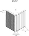
FIG. 3 is a partial perspective view of a composite filter shown inFIG. 2 . -
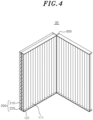
FIG. 4 is a rear perspective view ofFIG. 3 . -
FIG. 5 is an exploded perspective view ofFIG. 3 . -
FIG. 6 is a perspective view of the composite filter inFIG. 2 from which a connection member is omitted. -
FIG. 7 is a perspective view of the composite filter ofFIG. 2 . -
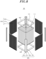
FIG. 8 is an exploded perspective view ofFIG. 7 . -
FIG. 9 is a perspective view when the composite filter ofFIG. 7 is in a folded state. -
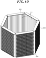
FIG. 10 is a perspective view illustrating a composite filter according to a second embodiment of the present disclosure. -
FIG. 11 is a conceptual diagram schematically illustrating a process for manufacturing a composite filter according to the present disclosure. -
FIG. 12 is a flowchart schematically illustrating a method for manufacturing a composite filter according to the present disclosure. - Hereinafter, a preferred embodiment of the present disclosure for implementing the spirit of the present disclosure will be described in more detail with reference to the accompanying drawings.
- However, in describing the present disclosure, detailed descriptions of known configurations or functions may be omitted to clarify the present disclosure.
- When an element is referred to as being 'connected' to, 'supported' by, or 'flowed' into another element, it should be understood that the element may be directly connected to, supported by, or flowed into the other element, but that other elements may exist in the middle.
- The terms used in the present disclosure are only used for describing specific embodiments, and are not intended to limit the present disclosure. Singular expressions include plural expressions unless the context clearly indicates otherwise.
- Terms including ordinal numbers, such as first and second, may be used for describing various elements, but the corresponding elements are not limited by these terms. These terms are only used for the purpose of distinguishing one element from another element.
- In the present specification, it is to be understood that the terms such as "including" are intended to indicate the existence of the certain features, areas, integers, steps, actions, elements and/or combinations thereof disclosed in the specification, and are not intended to preclude the possibility that one or more other certain features, areas, integers, steps, actions, elements and/or combinations thereof may exist or may be added.
- Furthermore, in the present disclosure, it is to be noted that expressions, such as the upper side and the lower side, are described based on the illustration of drawings, but may be modified if directions of corresponding objects are changed. Meanwhile, in the present specification, an up and down direction may be based on the up and down direction of
FIGS. 3 to 10 . - Hereinafter, a specific configuration of an
air purifier 1 according to a first embodiment of the present disclosure will be described with reference to the drawings. - Referring to
FIGS. 1 and2 , theair purifier 1 according to the first embodiment of the present disclosure can purify polluted air into clean air by filtering out dust, odor particles, and the like in the air introduced into theair purifier 1. In addition, theair purifier 1 can suck air outside the air purifier into the inside thereof and discharge clean air purified from the inside to the outside. Theair purifier 1 may include abody 10, ablower 20, and acomposite filter 30. - The
body 10 may support theblower 20 and thecomposite filter 30, and provide a space in which theblower 20 and thecomposite filter 30 are accommodated. Thebody 10 may include a case surrounding theblower 20 and thecomposite filter 30. - The
blower 20 may be driven to allow polluted air outside theair purifier 1 to be introduced into the inside of theair purifier 1. Theblower 20 may provide blowing force for causing the introduced air to pass through thecomposite filter 30. In addition, theblower 20 may be driven to discharge the clean air inside theair purifier 1 to the outside. For example, theblower 20 may be disposed at a lower side in thebody 10, and may be disposed inside thecomposite filter 30. - Referring to
FIGS. 3 to 5 , thecomposite filter 30 may filter the air introduced from the outside of theair purifier 1 into clean air. For example, it is possible to filter out dust, odor particles, and the like in the air. In addition, thecomposite filter 30 may be provided to be selectively foldable. For example, thecomposite filter 30 may be folded to minimize the volume of thecomposite filter 30 during delivery, and may be unfolded to perform the function of thecomposite filter 30 after delivery. Thecomposite filter 30 may include afilter unit 100, afiltration module 200, abracket 300, and aconnection member 400. - The
filter unit 100 is configured to allow air to pass therethrough, and can filter the air passing through thefilter unit 100 into clean air. Thefilter unit 100 may be formed to extend in an up and down direction. In addition, one surface of thefilter unit 100 through which air passes may be arranged in parallel with one surface of thefiltration module 200. For example, thefilter unit 100 may secondarily filter the air that has passed through thefiltration module 200 to be primarily filtered thereby, but may primarily filter the air before passing through thefilter module 200 depending on the flow direction of the air. Thefilter unit 100 may include afilter member 110 and afilter frame 120. - The
filter member 110 is configured to catch dust in the air, and can filter the air passing through thefilter member 110 into clean air. In addition, thefilter member 110 may be supported by thefilter frame 120. Further, thefilter member 110 may include afiltering part 111. - The
filtering part 111 may be provided to filter air. A plurality of pleats extending in an up and down direction may be formed in thefiltering part 111. For example, the plurality of pleats of thefiltering part 111 may be folded to be contracted in a direction perpendicular to the up and down direction or may be unfolded to be stretched in the direction perpendicular to the up and down direction. A portion of an edge of thefiltering part 111 may be surrounded by asupport 121 to be described later, and may be supported by thesupport 121. For example, upper and lower portions of thefiltering part 111 may be supported by thesupport 121. In addition, thebracket 300 may be attached to a side portion of thefiltering part 111. - Meanwhile, the
filtering part 111 may include a plurality of filteringparts 111, and at least some of the plurality of filteringparts 111 may be disposed adjacent to each other. The plurality of filteringparts 111 may include two ormore filtering parts 111, and more particularly, an even number offiltering parts 111 may be provided. Hereinafter, it is described that fourfilters 111 are provided, but this is only an example and any number offiltering parts 111 may be provided. - Referring to
FIGS. 6 to 8 , the plurality of filteringparts 111 may be integrally formed, and side surfaces thereof may be connected to each other so that the plurality of filteringparts 111 are rotatable with respect to each other. In other words, any one of the plurality of filteringparts 111 may rotate with respect to anotherfiltering part 111 adjacent thereto. For example, each of the plurality of filteringparts 111 may be configured to rotate about an imaginary axis extending in the up and down direction to be folded on theadjacent filtering part 111. - When each of the plurality of filtering
parts 111 is rotated with respect to each other to form an angle smaller than a straight angle with theadjacent filtering part 111, the plurality of filteringparts 111 may be arranged to form a loop-shaped path. In this case, the loop-shaped path may be defined as a path which starts from one point, passes through another point, and returns to the one point back. For example, the plurality of filteringparts 110 may include three filteringparts 111. As a detailed example, referring toFIG. 6 , the plurality of filteringparts 111 may be rotated with respect to each other to form a predetermined angle (90° in case of four filtering parts) with theadjacent filtering part 111. In this case, the predetermined angle may be an angle at which the area of the inner space surrounded by the plurality of filteringparts 111 is maximized when viewed from above. At this time, as shown inFIG. 2 , the plurality of filteringparts 111 viewed from above may form a rectangular loop. As such, when each of the plurality of filteringparts 111 forms an angle greater than 0° and less than 180° with theadjacent filtering part 111, it is defined as an unfolded state. - Referring to
FIG. 8 , the plurality of filteringparts 111 may rotate with respect to each other so that at least two filteringparts 111 adjacent to each other are arranged in parallel. As a detailed example, any onefiltering part 111 among the plurality of filteringparts 111 may be folded with respect to anotherfiltering part 111 connected to one side thereof by rotating with respect to the anotherfiltering part 111. In this case, the angle between the onefiltering part 111 and the anotherfiltering part 111 connected to the one side is 0°. In addition, the onefiltering part 111 may be unfolded with respect to further anotherfiltering part 111 connected to the other side by rotating with respect to the further anotherfiltering part 111. When the angle between each of the plurality of filteringparts 111 and thefiltering part 111 adjacent thereto is 0° or 180°, it is defined as a folded state. In this case, the angle between the onefiltering part 111 and the further anotherfiltering part 111 connected to the other side is 180°. - As described above, when the plurality of filtering
parts 111 are in the folded state, two filteringparts 111 adjacent to each other are arranged in parallel, so that theadjacent filtering parts 111 can be in close contact with each other. In addition, since the space between the plurality of filteringparts 111 is minimized, the volume of thefilter member 110 is minimized. - The
filter frame 120 may support thefilter member 110. For example, thefilter frame 120 is provided to surround an upper or lower side of thefilter member 110, and may support thefilter member 110 at the upper or lower side of thefilter member 110. Thefilter frame 120 may include a plurality ofsupports 121. - The
support 121 may support thefiltering part 111. For example, thesupport 121 may support thefiltering part 111 at the upper or lower side of thefiltering part 111. In addition, thesupport 121 may include a plurality ofsupports 121, and the plurality ofsupports 121 may be integrally formed. The plurality ofsupports 121 may be connected at side surfaces thereof to be rotatable with respect to each other. In other words, any one of the plurality ofsupports 121 may rotate with respect to anothersupport 121 adjacent thereto. - The
filter module 200 may be provided to filter the air introduced into thebody 10 from the outside. Thefilter module 200 may be configured as an additional dust collection filter to maximize dust collection performance, but may also be configured as a functional filter other than the purpose of dust collection. For example, thefilter module 200 may be a deodorizing filter that removes odors, a smoke filter that removes smoke particles, and a sick house filter that removes substances which cause sick house syndrome. As a detailed example, the deodorizing filter may include a corrugated-type or activated carbon-type deodorizing filter. Thefilter module 200 may be disposed in parallel with one or more of the plurality of filteringparts 111 of thefilter unit 100, and may be disposed outside thefilter unit 100. In other words, thefilter module 200 may be disposed to surround at least a portion of thefilter unit 100. Thefilter module 200 may filter the air primarily before the air introduced from the outside is filtered by thefilter unit 100, but when applied to an air purifier having a different flow direction, thefilter module 200 may filter the air that has been filtered by thefilter unit 100. - In addition, the
filter module 200 may include a plurality offilter modules 200, and the plurality offilter modules 200 may be disposed side by side with the plurality of filteringunits 111 and connected thereto, respectively. Thebracket 300 and theconnection member 400 may be attached to thefilter module 200 and thefiltering part 111 to connect thefilter module 200 and thefiltering part 111. For example, upper and lower surfaces of thefilter module 200 may be connected to thefiltering part 111 through theconnection member 400. Further, side surfaces of thefilter module 200 may be connected to thefiltering part 111 through thebracket 300. - In the present specification and some of the drawings, the
filter module 200 is expressed as being provided in plural corresponding to the number of thefiltering parts 111, but this is only an example and one ormore filter modules 200 may be provided independently of the number of thefiltering parts 111. Accordingly, thefilter module 200 may be provided in a smaller number than the number of thefiltering parts 111 to surround the plurality of filteringparts 111, and as a detailed example, as shown inFIGS. 3 to 5 , onefilter module 200 may be provided. - Meanwhile, the
filter module 200 may include anair purification member 210 and amodule frame 220. - The
air purification member 210 may be provided to filter air. Theair purification member 210 may be partially supported by themodule frame 220. For example, an upper or lower side of theair purification member 210 may be surrounded by themodule frame 220 and may be supported by themodule frame 220. In addition, thebracket 300 may be attached to a side surface of theair purification member 210. - Meanwhile,
protrusions 211 may be formed on at least one of both side surfaces of theair purification member 210. For example, theair purification member 210 may include a plurality of portions extending in the up and down direction and having repeatedly curved shapes, and theprotrusions 211 may be portions protruding outward among the repeatedly curved portions of theair purification member 210. Thebracket 300 may be attached to theprotrusions 211. Further, theprotrusions 211 may be formed to correspond toconcave portions 321 of thebracket 300 which will be described later. - The
module frame 220 may support theair purification member 210. Themodule frame 220 may support theair purification member 210 at the upper or lower side of theair purification member 210. - The
bracket 300 may support thefilter unit 100 and thefilter module 200 disposed adjacent to each other together. For example, thebracket 300 may support thefiltering parts 111 disposed adjacent to each other, among the plurality of filteringparts 111, to be rotatable with respect to each other. In addition, thebracket 300 may support thesupport parts 121 adjacent to each other, among the plurality ofsupports 121, to be rotatable with respect to each other. Thebracket 300 may connect thefilter unit 100 and thefilter module 200. For example, one side of thebracket 300 may be attached to the side surface of thefiltering part 111 or thesupport 121, and the other side of thebracket 300 may be attached to the side surface of thefilter module 200. Further, thebracket 300 may seal a gap between thefilter unit 100 and thefilter module 200. In addition, an adhesive or adhesive tape providing adhesive strength to be attached to the side surface of thefilter unit 100 and the side surface of thefilter module 200 may be provided on one surface of thebracket 300. Thebracket 300 may be formed to extend in the up and down direction along thefiltering part 111, and may be provided in plural. - Meanwhile, the
bracket 300 may be configured to be folded or unfolded in response to the rotation of thefiltering part 111 or thesupport 121. For example, when thefiltering part 111 is in the unfolded state (that is, when thecomposite filter 30 is in a first state in which thecomposite filter 30 is mounted in the air purifier 1), thebracket 300 may be in the unfolded state to form an angle larger than 0° and smaller than 180°. In addition, when thefiltering part 111 is in the folded state (that is, when thecomposite filter 30 is in a second state in which thecomposite filter 30 is removed from theair purifier 1 to be stored or transported), thebracket 300 disposed between some of the plurality of filteringparts 111 may be fully unfolded to form an angle of 180°, and thebracket 300 disposed between other some of the plurality of filteringparts 111 may be folded to form an angle of 0°. Thebracket 300 may be made of a flexible material including at least one of a porous material such as a foam, a nonwoven fabric, a synthetic fiber, and a natural fiber, for example. - The
bracket 300 may include a foldedportion 310 and anattachment portion 320. The foldedportion 310 and theattachment portion 320 may be integrally formed. - The folded
portion 310 may be selectively folded according to the rotation of theadjacent filtering parts 111 with respect to each other. The foldedportion 310 may be configured as a portion of thebracket 300 folded in response to the rotation of thefiltering part 111. For example, when thefiltering part 111 rotates with respect to theadjacent filtering part 111, an imaginary axis about which thefiltering part 111 rotates may correspond to the foldedportion 310. Further, the foldedportion 310 may be disposed between thefiltering part 111 and anotherfiltering part 111. The foldedportion 310 may be provided at the center of thebracket 300 to extend in the up and down direction. - Referring back to
FIG. 7 , theattachment portion 320 may be attached to thefiltering part 111 to connect the plurality of filteringparts 111. Theattachment portion 320 may include a plurality ofattachment portions 320, and the plurality ofattachment portions 320 may be respectively connected to the foldedportion 310 with the foldedportion 310 interposed therebetween. Further, the plurality ofattachment portions 320 may be respectively attached to theadjacent filtering parts 111 among the plurality of filteringparts 111. Meanwhile, theattachment portion 320 may be attached over thefilter member 110 and thefilter module 200, and may seal between thefilter member 110 and thefilter module 200. Specifically, theattachment portion 320 may be attached over the side surface of thefiltering part 111 of thefilter member 110 and the side surface of theair purification member 210 of thefilter module 200. Theattachment portion 320 may be attached to thesupport 121 to connect the plurality of filter frames 120. For example, theattachment portion 320 may extend from one edge of thefiltering part 111 to the other edge of theair purification member 210 in order to cover the side surfaces of thefiltering part 111 and theair purification member 210. - Meanwhile, one surface of the
attachment portion 320 may be provided with an adhesive surface that is adhered to the side surface of theair purification member 210. The adhesive surface may be adhered to the side surface of theair purification member 210. Further, aconcave portion 321 corresponding to at least a portion of theprotrusions 211 may be formed in theattachment portion 320. For example, when theattachment portion 320 is attached to the side surface of theair purification member 210, the concave portion 311 may be attached to theprotrusions 211. - The
connection member 400 may be attached to thefilter unit 100 and thefilter module 200 to connect thefilter unit 100 and thefilter module 200. For example, a portion of theconnection member 400 may be attached to the upper and lower surfaces of thefilter unit 100, and another portion of theconnection member 400 may be attached to the upper and lower surfaces of thefilter module 200. In addition, an adhesive or adhesive tape providing adhesive strength to be attached to the upper and lower surfaces of thefilter unit 100 and the upper and lower surfaces of thefilter module 200 may be provided on one surface of theconnection member 400. In addition, theconnection member 400 may seal a gap between thefilter unit 100 and thefilter module 200. In other words, theconnection member 400 may be attached to thesupport 121 and themodule frame 220 so that the gap between thesupport 121 of thefilter unit 100 and themodule frame 220 of thefilter module 200 is sealed. Theconnection member 400 may be a flexible material including at least one of a porous material such as a foam, a nonwoven fabric, a synthetic fiber, and a natural fiber, for example. However, as shown inFIG. 6 , theconnection member 400 may be omitted. - Hereinafter, the effect of the
composite filter 30 having the above-described configuration will be described. - The
composite filter 30 provides the effects to be described later, and above all, it is most meaningful that thecomposite filter 30 provides these effects economically with a simple configuration. - The
composite filter 30 can be easily converted into the unfolded state or the folded state by the plurality offilter units 100 configured to be rotatable with respect to each other. - In addition, when the
composite filter 30 is in the folded state, theadjacent filtering parts 111 are arranged to be in contact with each other, thereby minimizing the space between the plurality offilter members 110. When thecomposite filter 30 is in the folded state, the volume thereof can be minimized, which decreases the cost required for transportation. Further, after transportation, thecomposite filter 30 can be converted to the unfolded state to perform a filter function. - Meanwhile, the
bracket 300 can connect thefiltering part 111 and anotherfiltering part 111, and has an effect of improving durability by reinforcing the connection portion. Further, thebracket 300 and theconnection member 400 seal the gap between thefilter unit 100 and thefilter module 200 to prevent air from entering between thefilter unit 100 and thefilter module 200. To this end, it is possible to prevent the air that is not filtered by thefilter module 200 from flowing directly into thefilter unit 100, which increases the purification efficiency. - In addition to such configurations, according to a second embodiment of the present disclosure, six
filter members 110 may be provided. Hereinafter, the second embodiment of the present disclosure will be described with further reference toFIG. 10 . The description of the second embodiment description will be made mainly on the difference compared with the above-described embodiment, and the same descriptions and reference numerals are referred to the above-described embodiment. - In the second embodiment of the present disclosure, six
filter members 110 may be provided. Each of the plurality offilter members 110 may rotate with respect to theadjacent filter member 110 to form an angle of 120° with theadjacent filter member 110 when in the unfolded state. In addition, the plurality offilter members 110 viewed from above may form a hexagonal loop. Each of the plurality ofbrackets 300 may rotate in response to the rotation of the plurality offilter members 110. - The
filter members 111 can filter the air introduced from more various directions, and can improve the filtration efficiency. - Hereinafter, a composite filter manufacturing method S10 for manufacturing the composite filter with four sides according to the first embodiment of the present disclosure will be described with reference to
FIGS. 11 and12 . - In the composite filter manufacturing method S10, the
composite filter 30 may be manufactured by processing a laminated base material in which a filterunit base material 100 and a filtermodule base material 200 are stacked. For example, thecomposite filter 30 may be manufactured using afilter manufacturing apparatus 40 including acutter 41 and aconveyor 42. The composite filter manufacturing method S10 may include a laminated base material providing step S100, a filter module cutting step S200, a filter unit cutting step S300, and a bracket attachment step S400. - In the laminated base material providing step S100, the laminated base material may be provided by stacking a provided filter
module base material 200 on a provided filterunit base material 100. Here, the filterunit base material 100 means thefilter unit 100 before being cut, and the filtermodule base material 200 means thefilter module 200 before being cut. The laminated base material may be transferred to theconveyor 42, and may be transferred in one direction through theconveyor 42. - In the filter module cutting step S200, the filter
module base material 200 located at an upper side of the laminated base material moving on theconveyor 42 may be cut. For example, in the filter module cutting step S200, a plurality ofcutters 41 may cut the filtermodule base material 200 along a virtual cutting line extending in a thickness direction of the filtermodule base material 200. In this case, the filtermodule base material 200 may be divided into a plurality offilter modules 200. - In the filter unit cutting step S300, a part of the filter
unit base material 100 located at a lower side of the laminated base material moving on theconveyor 42 may be cut. For example, in the filter unit cutting step S300, the plurality ofcutters 41 cut the filtermodule base material 200 and then continuously move between the plurality offilter modules 200 along the cutting line to cut the filterunit base material 100 to a depth smaller than the thickness thereof. The depth at which the filterunit base material 100 is cut may be adjusted appropriately according to pleats formed in the filterunit base material 100 so that the filterunit base material 100 is not completely divided to form a plurality offilter members 110 connected to each other. In the case of manufacturing the composite filter with four sides according to the first embodiment of the present disclosure, as shown inFIG. 11 , when cutting a point corresponding to a multiple of 4, the cutting depth is adjusted so that the filterunit base material 100 is completely cut to split. - In the bracket attachment step S400, the
filter unit 100 and thefilter module 200 manufactured in the filter module cutting step S200 and the filter unit cutting step S300 may be connected through thebracket 300. In other words, in the bracket attachment step S400, thefilter unit 100 and thefilter module 200 are connected by attaching thebracket 300 to the side surfaces of thefilter unit 100 and thefilter module 200 disposed adjacent to each other. The bracket attachment step S400 may be performed after the filter module cutting step S200 and the filter unit cutting step S300. - The examples of the present disclosure have been described above as specific embodiments, but these are only examples, and the present disclosure is not limited thereto, and should be construed as having the widest scope according to the technical spirit disclosed in the present specification. A person skilled in the art may combine/substitute the disclosed embodiments to implement a pattern of a shape that is not disclosed, but it also does not depart from the scope of the present disclosure. In addition, those skilled in the art can easily change or modify the disclosed embodiments based on the present specification, and it is clear that such changes or modifications also belong to the scope of the present disclosure.
Claims (10)
- A composite filter comprising:a filter unit including a filter member for filtering air, the filter member having a plurality of filtering parts with side surfaces connected to each other so that the filtering parts are rotatable with respect to each other;at least one filter module arranged in parallel with at least one of the plurality of filtering parts; anda bracket supporting the filtering parts disposed adjacent to each other among the plurality of filtering parts and the filter module together so that the filtering parts disposed adjacent to each other are rotatable with respect to each other,wherein the bracket includes:a folded portion that is selectively folded according to the relative rotation of the filtering parts disposed adjacent to each other; anda plurality of attachment portions respectively connected to the folded portion with the folded portion interposed therebetween, and respectively attached to the side surfaces of the filtering parts disposed adjacent to each other,wherein the folded portion and the attachment portions are provided integrally with each other and are formed of a flexible material, andwherein each of the attachment portions extends to the side surface of the filter module adjacent thereto to seal a gap between the filtering part and the filter module.
- The composite filter of claim 1, wherein the plurality of filtering parts include three or more filtering parts, and when each of the plurality of filtering parts is rotated with respect to the filtering part adjacent thereto at an angle less than a straight angle, the plurality of filtering parts are arranged along a loop-like path.
- The composite filter of claim 2, wherein the number of the plurality of filtering parts is an even number.
- The composite filter of claim 1, wherein the plurality of filtering parts are rotatable with respect to each other so that at least two filtering parts adjacent to each other are arranged in parallel.
- The composite filter of claim 1, wherein the filter module includes:an air purification member for filtering air; anda module frame supporting an upper or lower side of the air purification member, andwherein protrusions are formed on at least one of both side surfaces of the air purification member.
- The composite filter of claim 5, wherein the bracket has a concave portion corresponding to at least a portion of the protrusions and includes an adhesive surface attached to the side surface of the air purification member.
- The composite filter of claim 5, wherein the filter unit further includes a filter frame having a support that supports an upper or lower side of the filtering parts, and
wherein the composite filter further includes a connection member attached to an upper side or lower side of the support and the module frame disposed adjacent to each other to seal a gap between the support and the module frame. - The composite filter of claim 1, wherein the filter module comprises a corrugated filter.
- An air purifier comprising:the composite filter of any one of claims 1 to 8; anda blower for providing blowing force to allow outside air to pass through the composite filter.
- A composite filter manufacturing method for manufacturing the composite filter of any one of claims 1 to 8 using a filter manufacturing apparatus, the method comprising:a laminated base material providing step of providing a laminated base material in which a filter unit base material and a filter module base material are stacked;a filter module cutting step of dividing and cutting the filter module base material into a plurality of filter modules by moving a cutter of the filter manufacturing apparatus along a virtual cutting line extending in a thickness direction of the laminated base material;a filter unit cutting step of cutting the filter unit base material to a depth smaller than a thickness of the filter unit base material by moving the cutter between the plurality of filter modules along the cutting line after the filter module cutting step; anda bracket attachment step of attaching the bracket to the side surfaces of the filtering part disposed adjacent to each other and the filter module,wherein the filter unit including the plurality of filtering parts and the plurality of supports is formed from the filter unit base material through the filter unit cutting step.
Applications Claiming Priority (2)
| Application Number | Priority Date | Filing Date | Title |
|---|---|---|---|
| KR1020200082122A KR20220004369A (en) | 2020-07-03 | 2020-07-03 | Composite filter and air clearner including the same |
| PCT/KR2021/008153 WO2022005154A1 (en) | 2020-07-03 | 2021-06-29 | Composite filter and air purifier including same |
Publications (2)
| Publication Number | Publication Date |
|---|---|
| EP4176958A1 true EP4176958A1 (en) | 2023-05-10 |
| EP4176958A4 EP4176958A4 (en) | 2024-06-26 |
Family
ID=79316511
Family Applications (1)
| Application Number | Title | Priority Date | Filing Date |
|---|---|---|---|
| EP21833904.2A Pending EP4176958A4 (en) | 2020-07-03 | 2021-06-29 | COMPOSITE FILTER AND AIR PURIFIER |
Country Status (6)
| Country | Link |
|---|---|
| US (1) | US20230266025A1 (en) |
| EP (1) | EP4176958A4 (en) |
| JP (1) | JP7741116B2 (en) |
| KR (1) | KR20220004369A (en) |
| CN (1) | CN115768540A (en) |
| WO (1) | WO2022005154A1 (en) |
Families Citing this family (2)
| Publication number | Priority date | Publication date | Assignee | Title |
|---|---|---|---|---|
| USD1055248S1 (en) * | 2022-05-27 | 2024-12-24 | Mullet Tools, LLC | Air scrubber |
| USD1034940S1 (en) * | 2022-06-02 | 2024-07-09 | Airdoctor, Llc | Air purifier unit |
Family Cites Families (17)
| Publication number | Priority date | Publication date | Assignee | Title |
|---|---|---|---|---|
| DE1086977B (en) * | 1956-05-31 | 1960-08-11 | Delbag Luftfilter Ges Mit Besc | Filter housing wall for V-shaped, exchangeable air filter cassettes |
| JP3448672B2 (en) * | 1993-10-19 | 2003-09-22 | 日本バイリーン株式会社 | Folding filter |
| EP1270059A1 (en) * | 2001-06-28 | 2003-01-02 | Frank Hammes | Single-use filter element and folding pattern for the production of the filter element |
| KR200396850Y1 (en) * | 2005-07-12 | 2005-09-27 | 이종만 | An air purifier having filter using charcoal |
| US7410520B2 (en) * | 2006-12-22 | 2008-08-12 | Hamilton Beach Brands, Inc. | Foldable filter for an air filtration unit and method |
| JP2010017630A (en) * | 2008-07-09 | 2010-01-28 | Toyota Boshoku Corp | Method for manufacturing air filter and processing mold |
| KR101342606B1 (en) * | 2012-07-27 | 2013-12-17 | 주식회사 젬백스앤카엘 | Chemical filter for easy replacement of filter media |
| WO2016070039A1 (en) * | 2014-10-31 | 2016-05-06 | Ahlstrom Corporation | Self-supporting pleatable fibrous web especially useful as oil filter media and oil filter comprising the same |
| KR101897561B1 (en) * | 2015-10-21 | 2018-09-12 | 코웨이 주식회사 | Shape-variable filter frame and air cleaner having the same |
| WO2017026761A1 (en) | 2015-08-12 | 2017-02-16 | 코웨이 주식회사 | Air purifier |
| JP6700409B2 (en) * | 2016-02-26 | 2020-05-27 | エルジー エレクトロニクス インコーポレイティド | Air cleaner |
| KR101776913B1 (en) * | 2016-03-14 | 2017-09-08 | (주)쓰리에이씨 | 3D deodorization filter |
| DE102016009603A1 (en) * | 2016-08-09 | 2017-08-03 | Mann + Hummel Gmbh | Filter element and filter assembly |
| CN108722031B (en) | 2017-04-24 | 2022-03-08 | 布鲁雅尔公司 | Air filter unit |
| JP2019025380A (en) * | 2017-07-25 | 2019-02-21 | ダイキン工業株式会社 | Air filter unit, air filter medium sheet for pleats, and method for manufacturing air filter unit |
| CN207641181U (en) * | 2017-12-06 | 2018-07-24 | 何著好 | A kind of air purifying filter core of foldable structure |
| ES3001938T3 (en) * | 2018-10-08 | 2025-03-06 | Filtereasy Llc | Folding air filter assemblies |
-
2020
- 2020-07-03 KR KR1020200082122A patent/KR20220004369A/en active Pending
-
2021
- 2021-06-29 WO PCT/KR2021/008153 patent/WO2022005154A1/en not_active Ceased
- 2021-06-29 EP EP21833904.2A patent/EP4176958A4/en active Pending
- 2021-06-29 US US18/004,107 patent/US20230266025A1/en active Pending
- 2021-06-29 JP JP2022581665A patent/JP7741116B2/en active Active
- 2021-06-29 CN CN202180047541.8A patent/CN115768540A/en active Pending
Also Published As
| Publication number | Publication date |
|---|---|
| EP4176958A4 (en) | 2024-06-26 |
| US20230266025A1 (en) | 2023-08-24 |
| JP7741116B2 (en) | 2025-09-17 |
| CN115768540A (en) | 2023-03-07 |
| JP2023533240A (en) | 2023-08-02 |
| WO2022005154A1 (en) | 2022-01-06 |
| KR20220004369A (en) | 2022-01-11 |
Similar Documents
| Publication | Publication Date | Title |
|---|---|---|
| US12274969B2 (en) | Vehicle cabin filter assembly | |
| US20230266025A1 (en) | Composite filter and air purifier including same | |
| US12257883B2 (en) | Vehicle cabin filter assembly | |
| WO2020008212A1 (en) | Vehicle cabin filter assembly | |
| US20250025817A1 (en) | Filter unit and method for manufacturing the same | |
| US20230233971A1 (en) | Air filter and air purifier comprising same | |
| US12453938B2 (en) | Filter frame and air purifier comprising same | |
| KR20220006223A (en) | Air filter and air clearner including the same | |
| EP4289496A1 (en) | Filter holder, filter assembly, and air purifier comprising same | |
| US20240344737A1 (en) | Filter module and air purifier comprising same | |
| WO2020008213A1 (en) | Vehicle cabin filter assembly | |
| WO2020008215A1 (en) | Vehicle cabin filter assembly | |
| JP2902414B2 (en) | Filter for air purifier | |
| JPH11114333A (en) | Air purifying filter and air purifier using the same | |
| JP3688866B2 (en) | Air cleaner | |
| KR20220118694A (en) | Filter holder, filter assembly and clearner including the same | |
| JP2001252512A (en) | Air cleaner | |
| JP2024100599A (en) | Air cleaner and filter attachment structure of air cleaner | |
| JP2002306916A (en) | Air filter unit | |
| KR20250132849A (en) | Multi filter assembly | |
| KR20220118704A (en) | Filter assembly and air clearner including the same | |
| JPH07213843A (en) | Filter for air cleaning | |
| JPH11267200A (en) | Sterilizing method using ozone gas |
Legal Events
| Date | Code | Title | Description |
|---|---|---|---|
| STAA | Information on the status of an ep patent application or granted ep patent |
Free format text: STATUS: THE INTERNATIONAL PUBLICATION HAS BEEN MADE |
|
| PUAI | Public reference made under article 153(3) epc to a published international application that has entered the european phase |
Free format text: ORIGINAL CODE: 0009012 |
|
| STAA | Information on the status of an ep patent application or granted ep patent |
Free format text: STATUS: REQUEST FOR EXAMINATION WAS MADE |
|
| 17P | Request for examination filed |
Effective date: 20230102 |
|
| AK | Designated contracting states |
Kind code of ref document: A1 Designated state(s): AL AT BE BG CH CY CZ DE DK EE ES FI FR GB GR HR HU IE IS IT LI LT LU LV MC MK MT NL NO PL PT RO RS SE SI SK SM TR |
|
| DAV | Request for validation of the european patent (deleted) | ||
| DAX | Request for extension of the european patent (deleted) | ||
| A4 | Supplementary search report drawn up and despatched |
Effective date: 20240524 |
|
| RIC1 | Information provided on ipc code assigned before grant |
Ipc: B01D 46/42 20060101ALI20240517BHEP Ipc: B01D 46/00 20220101AFI20240517BHEP |