EP4176833A1 - Angle-adjustable robot arm for minimally invasive surgery, surgical robot and method for producing same - Google Patents
Angle-adjustable robot arm for minimally invasive surgery, surgical robot and method for producing same Download PDFInfo
- Publication number
- EP4176833A1 EP4176833A1 EP22205321.7A EP22205321A EP4176833A1 EP 4176833 A1 EP4176833 A1 EP 4176833A1 EP 22205321 A EP22205321 A EP 22205321A EP 4176833 A1 EP4176833 A1 EP 4176833A1
- Authority
- EP
- European Patent Office
- Prior art keywords
- segment
- rack
- arm segment
- arm
- pinion
- Prior art date
- Legal status (The legal status is an assumption and is not a legal conclusion. Google has not performed a legal analysis and makes no representation as to the accuracy of the status listed.)
- Pending
Links
- 238000002324 minimally invasive surgery Methods 0.000 title claims abstract description 18
- 238000004519 manufacturing process Methods 0.000 title claims abstract description 14
- 230000033001 locomotion Effects 0.000 claims abstract description 42
- 230000015572 biosynthetic process Effects 0.000 claims description 13
- 238000005755 formation reaction Methods 0.000 claims description 13
- 238000005452 bending Methods 0.000 description 17
- 230000007246 mechanism Effects 0.000 description 10
- 229910001000 nickel titanium Inorganic materials 0.000 description 10
- 239000000654 additive Substances 0.000 description 6
- 230000000996 additive effect Effects 0.000 description 6
- 238000013461 design Methods 0.000 description 6
- 238000007789 sealing Methods 0.000 description 6
- 238000001356 surgical procedure Methods 0.000 description 6
- 238000010146 3D printing Methods 0.000 description 5
- 238000000034 method Methods 0.000 description 5
- 230000008859 change Effects 0.000 description 4
- 238000011161 development Methods 0.000 description 4
- 230000008569 process Effects 0.000 description 4
- 239000012636 effector Substances 0.000 description 3
- 238000002357 laparoscopic surgery Methods 0.000 description 3
- 210000000683 abdominal cavity Anatomy 0.000 description 2
- 238000005520 cutting process Methods 0.000 description 2
- 229910052751 metal Inorganic materials 0.000 description 2
- 239000002184 metal Substances 0.000 description 2
- 238000004080 punching Methods 0.000 description 2
- 238000012360 testing method Methods 0.000 description 2
- XLYOFNOQVPJJNP-UHFFFAOYSA-N water Substances O XLYOFNOQVPJJNP-UHFFFAOYSA-N 0.000 description 2
- 210000003815 abdominal wall Anatomy 0.000 description 1
- 238000004026 adhesive bonding Methods 0.000 description 1
- 238000004458 analytical method Methods 0.000 description 1
- 230000005540 biological transmission Effects 0.000 description 1
- 238000005219 brazing Methods 0.000 description 1
- 239000000969 carrier Substances 0.000 description 1
- 238000006243 chemical reaction Methods 0.000 description 1
- 238000002192 cholecystectomy Methods 0.000 description 1
- 238000010073 coating (rubber) Methods 0.000 description 1
- 238000002052 colonoscopy Methods 0.000 description 1
- 238000004590 computer program Methods 0.000 description 1
- 238000010276 construction Methods 0.000 description 1
- 230000001419 dependent effect Effects 0.000 description 1
- 238000006073 displacement reaction Methods 0.000 description 1
- 238000009826 distribution Methods 0.000 description 1
- 230000000694 effects Effects 0.000 description 1
- 238000001839 endoscopy Methods 0.000 description 1
- 238000005516 engineering process Methods 0.000 description 1
- 238000011156 evaluation Methods 0.000 description 1
- 239000012530 fluid Substances 0.000 description 1
- 230000002496 gastric effect Effects 0.000 description 1
- 238000003384 imaging method Methods 0.000 description 1
- 238000003754 machining Methods 0.000 description 1
- 239000000463 material Substances 0.000 description 1
- 238000003801 milling Methods 0.000 description 1
- 238000005065 mining Methods 0.000 description 1
- 238000004806 packaging method and process Methods 0.000 description 1
- 230000008707 rearrangement Effects 0.000 description 1
- 238000012552 review Methods 0.000 description 1
- 239000000523 sample Substances 0.000 description 1
- 229920002379 silicone rubber Polymers 0.000 description 1
- 239000004945 silicone rubber Substances 0.000 description 1
- 238000003892 spreading Methods 0.000 description 1
- 230000007480 spreading Effects 0.000 description 1
- 238000003466 welding Methods 0.000 description 1
Images


Classifications
-
- A—HUMAN NECESSITIES
- A61—MEDICAL OR VETERINARY SCIENCE; HYGIENE
- A61B—DIAGNOSIS; SURGERY; IDENTIFICATION
- A61B34/00—Computer-aided surgery; Manipulators or robots specially adapted for use in surgery
- A61B34/30—Surgical robots
-
- B—PERFORMING OPERATIONS; TRANSPORTING
- B25—HAND TOOLS; PORTABLE POWER-DRIVEN TOOLS; MANIPULATORS
- B25J—MANIPULATORS; CHAMBERS PROVIDED WITH MANIPULATION DEVICES
- B25J17/00—Joints
-
- B—PERFORMING OPERATIONS; TRANSPORTING
- B25—HAND TOOLS; PORTABLE POWER-DRIVEN TOOLS; MANIPULATORS
- B25J—MANIPULATORS; CHAMBERS PROVIDED WITH MANIPULATION DEVICES
- B25J18/00—Arms
-
- A—HUMAN NECESSITIES
- A61—MEDICAL OR VETERINARY SCIENCE; HYGIENE
- A61B—DIAGNOSIS; SURGERY; IDENTIFICATION
- A61B34/00—Computer-aided surgery; Manipulators or robots specially adapted for use in surgery
- A61B34/30—Surgical robots
- A61B2034/302—Surgical robots specifically adapted for manipulations within body cavities, e.g. within abdominal or thoracic cavities
Definitions
- the invention relates to a bendable robot arm for minimally invasive surgery, a surgical robot and a method for producing a bendable robot arm.
- Robots are increasingly being used in the field of surgery. These can be so-called telemanipulators, in which robotic systems directly execute a movement specified by a person performing the operation. Alternatively, robots in the narrower sense can be used, which execute movements at least partially autonomously based on previous specifications by a user and/or sensor data.
- actuation with NiTi wires has become particularly popular.
- flaps on robot arms can be opened via such wires, which deflect instruments or instrument arms (cf. Bardou, Berengere et al.: Design of a telemanipulated system for transluminal surgery, 31st Annual International Conference of the IEEE EMBS, 2009 ; Swanstrom, Lee et al.: Development of a New Access Device for Transgastric Surgery, The Society for Surgery of the Alimentary Tract, 2005 ; as well as De Donno, Antonio et al.: Introducing STRAS: a New Flexible Robotic System for Minimally Invasive Surgery, 2013 IEEE International Conference on Robotics and Automation (ICRA), 2013 ).
- ICRA Robotics and Automation
- An angle adjustment can also be achieved using a coiled cable, which, in contrast to a NiTi wire, cannot be subjected to tension or pressure, but only to tension.
- a coiled cable can be wrapped around a post with one turn.
- the cable On an opposite side, the cable may be wrapped around a second post in the opposite direction, such that if the cable is pulled on one side while trailing the cable on the other side, a robotic arm will angle in the appropriate direction. In this way, rotation in both directions is possible (cf. for example Can, Salman et al.: Design, Development and Evaluation of a Highly Versatile Robotic Platform for Minimally Invasive Single-Port Surgery, The Fourth IEEE RAS/EMBS International Conference on Biomedical Robotics and Biomechatronics, 2012 .).
- angular adjustment can be achieved by bending the first segment, i.e. the segment closest to a base plate, while bending the second segment in the opposite direction.
- first segment i.e. the segment closest to a base plate
- second segment in the opposite direction.
- SURS Unfoldable Robotic System
- An angle adjustment can take place in particular through the targeted curvature of individual segments that consist of NiTi wire.
- several robot arms of a robot are pushed apart, for example by means of a parallelogram mechanism.
- a parallelogram mechanism see Xu, Kai et al.: System Design of an Insertable Robotic Effector Platform for Single Port Access (SPA) Surgery, The 2009 IEEE/RSJ International Conference on Intelligent Robots and Systems, 2009 ) the parallelogram arm is erected by retracting a rail, while a forward displacement of the rail leads to the positioning of the flexible robot part.
- the document DE 10 2010 034 380 A1 discloses a joint section of an endoscope shaft for articulated connection of a distal part of the endoscope shaft to a proximal part of the endoscope shaft.
- the distal shaft part is different over two long, rigid joint rods are connected to the proximal shaft part, each of which attaches to a joint on the distal and proximal shaft part.
- the object of the invention is to specify improved technologies for surgical robots with robot arms that can be bent, in which, in particular, mechanical complexity is low and efficient operation is ensured.
- an articulated robotic arm for minimally invasive surgery has a proximal arm segment, which extends along a longitudinal axis of the robot arm, and a distal arm segment, which is pivotally connected to the proximal arm segment about a pivot axis orthogonal to the longitudinal axis.
- the distal arm segment includes a pinion segment formed with pinion teeth arranged in the shape of a pinion about the pivot axis.
- a rack member is disposed on the proximal arm segment such that the rack member is translationally movable longitudinally of the rack member parallel to the longitudinal axis, and rack teeth formed on the rack member mesh with the pinion teeth such that longitudinal movement of the rack member is via converting the rack teeth and the pinion teeth into rotational movement of the arm distal segment about the pivot axis; and pivoting the arm distal segment relative to the arm proximal segment about the pivot axis.
- a surgical robot in particular for minimally invasive surgery, which has a bendable robot arm according to the disclosure.
- a method for producing an articulated robot arm comprises the steps of providing a proximal arm segment, the direction of extension of which defines a longitudinal axis of the robot arm, providing a distal arm segment with a pinion segment which is formed with pinion teeth arranged in the form of a pinion about a pivot axis, connecting the distal arm segment to the proximal one Arm segment such that the distal arm segment is pivotable about the pivot axis relative to the proximal arm segment and the pivot axis is orthogonal to the longitudinal axis, and arranging a rack and pinion member on the proximal arm segment.
- the rack member is disposed on the proximal arm segment such that the rack member is translationally movable in the longitudinal direction of the rack member parallel to the longitudinal axis, and rack teeth formed on the rack member mesh with the pinion teeth so that longitudinal movement of the rack member is via converting the rack teeth and the pinion teeth into rotational movement of the arm distal segment about the pivot axis; and pivoting the arm distal segment relative to the arm proximal segment about the pivot axis.
- robot and robot arm refer both to robots in the narrower sense, which perform autonomous or semi-autonomous movements, and to telemanipulation systems in which robotic arms perform a movement specified directly by an operator.
- Conceptually included here are also combinations of the two concepts.
- proximal designates a direction or arrangement facing a central main part of the robot.
- distal designates a direction or arrangement facing away from the central main part and towards the operation site.
- a bend of a bendable robot arm can be provided without using cables or wires for this bend.
- cables or wires can be provided for additional movements and/or degrees of freedom of the robot arm.
- the pinion teeth can be formed as formations of the distal arm segment.
- the pinion segment forms a portion of the distal arm segment.
- the pinion teeth can be produced together with the distal arm segment by means of an additive process, in particular 3D printing, the pinion teeth can be molded onto the distal arm segment or the pinion teeth can be formed out of the distal arm segment, for example by means of machining such as milling or by punching or cutting, for example laser or water jet cutting. Forming the pinion teeth as formations of the distal arm segment can reduce the number of connecting elements required and the associated material costs and assembly time.
- the pinion teeth may be manufactured separately and attached to the distal arm segment, such as by gluing, welding, brazing, screws or rivets.
- the pinion segment forms a separate element which is arranged on and attached to the distal arm segment.
- a pinion or a portion of a pinion (in particular in the form of a circular segment with teeth along the circumference) can be arranged on the distal arm segment and firmly connected to it.
- the pinion teeth may extend about the pivot axis over a limited angular range.
- a section of a pinion can be formed and/or arranged on the distal arm segment with the pinion segment.
- the limited angular range can correspond to a radius of movement of the bending of the robot arm.
- the pinion teeth can span an angle between full extension of the distal arm segment relative to the proximal arm segment (corresponding to 0°) and a right angle between the proximal arm segment and the distal arm segment (90°).
- the distal arm segment may include a second pinion segment having pinion teeth disposed about the pivot axis and spaced from the pinion segment along the pivot axis on the distal arm segment.
- the pinion segments can be arranged along opposite sides of the distal arm segment along a direction predetermined by the pivot axis.
- rack teeth engage both pinion segments to pivot the arm distal segment.
- the rack member may have two sets of rack teeth, the two sets of rack teeth being parallel and spaced apart in the direction of the pivot axis such that the first set of rack teeth meshes with the pinion teeth of the pinion segment and the second set of rack teeth meshes with the Pinion teeth of the second pinion segment is engaged.
- the rack element can have only one set of rack teeth, with the rack teeth being designed so wide that they engage with both pinion segments in order to pivot the distal arm segment.
- the rack member may be formed with a proximal rack segment and a distal rack segment longitudinally adjoining the proximal rack segment, the distal rack segment being wider than the proximal rack segment in the direction of the pivot axis.
- the rack teeth can be arranged in the area of the distal toothed rack element.
- the proximal rack segment may be free of rack teeth.
- the sets of rack teeth may be parallel and spaced apart in the direction of the pivot axis on the distal rack segment.
- the proximal arm segment can have a guide channel running along the longitudinal axis, in which the rack element, in particular with a proximal rack segment, is arranged and guided at least in sections.
- the guide channel can have a V-shape or U-shape in cross section.
- the guide channel can extend the entire length of the proximal arm segment.
- the guide channel can extend only partially along the proximal arm segment, the length of the guide channel corresponding to at least a length by which the toothed rack element can be moved parallel to the longitudinal axis for maximum angling of the distal arm segment.
- the toothed rack element can have a projecting guide element which is arranged in the guide channel and is linearly guided in it.
- the proximal arm segment can have an arm segment guide element, which is preferably arranged on a distal end of the proximal arm segment so as to protrude in the longitudinal direction, in particular formed in one piece on the proximal arm segment or formed as a separate element and on which attached to the proximal arm segment.
- the arm segment guide element can be designed as a guide rod.
- the toothed rack element has a toothed rack element guide channel in which the arm segment guide element is arranged and guided at least in sections.
- the rack member guide channel may be located on a side of the rack member opposite the rack teeth, particularly on a side of the distal rack member opposite the rack teeth.
- the arm segment guide element and the rack element guide channel preferably have a non-round cross section, in particular a rectangular cross section.
- the distal arm segment can be formed, at least in sections, as a flexible arm segment which can be bent continuously or quasi-continuously along its length.
- the distal arm segment can be formed distally of a region in which the pinion segment is arranged according to a flexible robot structure, for example according to the principles of flexible robot structures, which are known as such from the prior art, or according to flexible robot structures deviating from the prior art .
- the flexible arm segment can be formed with at least three pull-push means, which are arranged parallel to one another along a longitudinal extent of the flexible arm segment and can be displaced along the longitudinal extent.
- Each pull-push device can be assigned a corresponding linear actuator, which is set up to move the relevant pull-push device along the longitudinal extension of the flexible arm segment.
- the corresponding linear actuators can be part of the bendable robot arm, or the relevant pull-push means can be set up to be functionally connected to a corresponding linear actuator, which is arranged outside of the bendable robot arm, for example as part of a surgical robot to which the bendable robot arm is assigned is.
- a linear actuator can be an actuator that provides a linear movement directly or an actuator that provides another form of movement, for example rotation, in conjunction with a mechanism that converts the movement provided by the actuator into a linear movement.
- the pull-push means can be wires, in particular NiTi wires, ie wires made from a nickel-titanium alloy.
- the wires can have a sufficiently high buckling stiffness to be used as a push-pull device in both a pull and a push mode.
- the length of a pull-push device that is arranged centrally in relation to the cross section of the flexible arm segment can remain constant, i.e. the corresponding linear actuator cannot move while one or more of the remaining pull-push devices moved, ie shifted along the length of the flexible arm segment.
- the flexible arm segment can be formed with at least five pull-push means, it being possible for the configurations explained above with regard to the pull-push means to be provided accordingly.
- the length of a relative to the cross section of the flexible arm segment centrally arranged pull-push means remain constant, while one or more of the remaining pull-push means moves, so along the longitudinal extent of the flexible arm segment, are shifted.
- two of the non-central pull-push means can be actuated antagonistically, so that one pull-push means is pushed in a distal direction, while the other pull-push means is in a direction related to the central pull-push Mean opposite side is pulled in a proximal direction, so that a bending of the flexible arm segment is achieved.
- the distal arm segment can be formed with a fixed segment which is connected to the proximal arm segment so that it can pivot about the pivot axis and which has the pinion segment, with the flexible arm segment being attached directly or indirectly to the fixed segment connects.
- pull-push elements of the flexible arm segment can be guided through the proximal arm segment and the fixed segment of the distal arm segment.
- the fixed segment can have element guide channels for guiding the push-pull elements. A different distribution of the push-pull elements in the distal arm segment compared to the proximal arm segment can be achieved by means of the element guide channels.
- the pull-push elements are arranged linearly next to one another in the proximal arm segment, while they are arranged along the distal arm segment in accordance with a flexible arm segment, in particular in a circle around a central pull-push element.
- an arrangement of the element guide channels corresponds to an arrangement of the pull-push elements in the distal arm segment, so that the pull-push elements are rearranged before entering the element guide channels compared to their arrangement in the proximal arm segment become.
- the element guide channels can be designed in such a way that they prescribe a rearrangement of the push-pull elements to guide them directly.
- the arrangement of the inlets of the element guide channels facing the proximal arm segment corresponds to an arrangement of the pull-push elements in the proximal arm segment and an arrangement of the outlets of the element guide channels facing away from the proximal arm segment corresponds to an arrangement of the pull-push elements in the distal arm segment.
- the distal arm segment can be formed at least in sections as a discrete robotic arm segment with segments arranged one behind the other along its length, the discrete robotic arm segment being able to be angled in segments along its length.
- the discrete robotic arm segment distal to an area in which the pinion segment is arranged can be designed according to a discrete robot structure, for example according to the principles of discrete robot structures which are known as such from the prior art, or according to discrete robot structures deviating from the prior art .
- the flexible arm segment and the discrete robotic arm segment can be arranged one behind the other in a suitable order along the longitudinal extent of the distal arm segment, with both the flexible Arm segment and the discrete-robotic arm segment are formed distally of an area in which the pinion segment is arranged, in particular distally of a fixed segment of the distal arm segment.
- the bendable robot arm can have a linear actuator which is connected to the rack element and is set up to move the rack element back and forth translationally parallel to the longitudinal axis.
- the toothed rack element can be set up to be functionally connected to a corresponding linear actuator which is arranged outside of the bendable robot arm, for example as part of a surgical robot to which the bendable robot arm is assigned.
- a linear actuator can be an actuator that provides a linear movement directly or an actuator that provides another form of movement, for example rotation, in conjunction with a mechanism that converts the movement provided by the actuator into a linear movement.
- the distal arm segment can be pivotally connected to the proximal arm segment by means of a screw connection about the pivot axis.
- a screw connection for example a rivet connection, a connection via a separate joint component or a direct and rotationally movable form-fitting connection between the distal arm segment and the proximal arm segment can be provided.
- the proximal arm segment may be formed with a link formation which extends to and is pivotally connected to the distal arm segment.
- the connecting formation extends between two pinion segments of the distal arm segment and is pivotably fixed between them.
- the pinion segments can be formed as formations of flank elements of the distal arm segment, and the connecting formation can extend between the flank elements and be pivotably fixed between them.
- the connector formation may be integrally formed with the proximal arm segment or may be separately formed and fixedly attached thereto.
- the surgical robot can be designed as a robot that can be mounted in the body of a patient. Provision can be made here for individual elements of the surgical robot, for example comprising a plurality of robot arms, to be introduced separately into the patient's body and to be connected to one another in the patient's body to form the surgical robot.
- the surgical robot as a robot that can be installed in a patient's body, the fact that the surgical robot is introduced into the patient's body in several separate elements can make it possible to introduce the surgical robot into the patient's body through a smaller incision in the patient's abdominal wall than would otherwise be possible.
- a sealing fixing element can be provided which, after the robot arms have been arranged in the housing, is introduced into the housing from outside the patient's body and encloses the robot arms in a sealing and fixing manner.
- the spreading of the distal arm segment can include the punching out of a metal sheet and the bending of the punched metal sheet to form the distal arm segment.
- providing the distal arm segment can include producing the distal arm segment at least in sections by means of an additive manufacturing process.
- provision can be made to produce the distal arm segment using a 3D printing process.
- the pinion segment in particular can be 3D-printed.
- each or all of the elements of the bendable robot arm can be produced by means of an additive manufacturing process, for example 3D printing. Accordingly, it can be provided for the bendable robot arm that one, some or all elements are produced by means of an additive manufacturing process, for example 3D printing.
- the disclosure extends to a computer program product comprising instructions which, when the program is executed on a device for additive manufacturing, in particular a 3D printer, cause additive manufacturing of the bendable robot arm or its components.
- the 1 shows an embodiment of an articulated robotic arm for minimally invasive surgery.
- the robot arm is formed with a proximal arm segment 1 and a distal arm segment 2 .
- the proximal arm segment 1 is formed as a rigid segment.
- the distal arm segment 2 is formed with a fixed segment 3 and a flexible arm segment 4 distally adjoining it.
- the flexible arm segment 4 has five NiTi wires as pull-push means 5 .
- two pairs of push-pull means 5 each acting antagonistically are arranged around a central axis of the flexible arm segment 4 . A pull on one of the pull-push means 5 of a pair while pushing the other pull-push means 5 of the pair causes an angling in the form of a bend in the flexible arm segment 4.
- an end effector 6 of the robot arm which is in the embodiment of 1 is a tong member whose jaws are opened and closed to provide a gripping motion.
- proximal arm segment 1 and the distal arm segment 2 are angled connected to each other.
- two flanks of the fixed segment 3 are arranged around a connecting formation 7 and are pivotably connected to the connecting formation by means of a screw connection 8 through the flanks and through the connecting formation 7 .
- a pivot axis of the distal arm segment 2 relative to the proximal arm segment 1 is thus defined by the screw connection 8 .
- the distal arm segment 2 has two pinion segments 9 formed from the flanks, which are formed with pinion teeth 10, the pinion teeth 10 being arranged around the pivot axis in accordance with a pinion.
- Rack teeth 11 of a rack member 12 mesh with the pinion teeth.
- an angling of the distal arm segment 2, namely the fixed segment 3, relative to the proximal arm segment 1 can be achieved about the pivot axis, with the linear or translational movement of the rack teeth 11 via the engagement with the pinion teeth 10 a rotation of the pinion segments 9 and thus the fixed Segment 3 cause about the pivot axis.
- This angling of the distal arm segment 2 is in principle independent of an angling caused by a bending of the flexible arm segment 4, although a relative change in path of the pull-push means 5 when the fixed segment 3 is bent can have an influence on the flexible arm segment 4.
- Figures 2B and 2C illustrate the angling of the distal arm segment 2 relative to the proximal arm segment 1 and the linear guidance of the toothed rack element 12 during the angling.
- Figure 2B a view of the proximal end of the proximal arm segment 1.
- the Figure 2C shows a view of the distal end of the proximal arm segment 1 with the distal arm segment 2 pivotably arranged thereon. It can be seen that the push-pull elements 5 of the flexible arm segment 4 over the entire length of the proximal arm segment 1 up to its proximal be led to the end.
- linear actuators can be operatively connected to the pull-push elements 5 in order to move them linearly and thus to actuate the flexible arm segment 4 .
- the rack member 12 is formed with a narrow proximal rack segment 13 and a wider distal rack segment 14 .
- two sets of rack teeth 11 are formed on opposite sides of the distal rack segment 14, which are each in engagement with the pinion teeth 10 of one of the pinion segments 9 of the distal arm segment 2 in the bendable robot arm.
- the Figure 4A shows the proximal arm segment 1.
- the Figure 4B 1 is a detailed view of the distal end of the proximal arm segment 1.
- a guide channel 15 is formed in the proximal arm segment 1 and accommodates the narrow proximal toothed rack segment 13 for linear guidance of the toothed rack element 12 in the longitudinal direction of the proximal arm segment 1.
- the guide channel 15 is formed in a cross section approximate to a U-shape, and the cross section of the proximal rack segment 13 is adapted to the cross section of the guide channel 15, as shown in FIG Figure 2B can be seen.
- the proximal arm segment 1 has a guide rod 16, which is linearly guided in a rack element guide channel 17, whereby additional guidance of the translational movement of the rack element 12 for bending the distal arm segment 2 is provided.
- the stylet 16 is disposed at the distal end of the proximal arm segment 1 and protrudes longitudinally therefrom.
- the rack member guide channel 17 is formed on the underside of the wide distal rack segment 14 and the cross-sectional shapes of the guide rod 16 and the Rack element guide channel 17 are matched to one another in such a way that the rack element 12 can run with the rack element guide channel 17 on the guide rod 16 in the sense of a linear guide, as for example in Figure 2A and 2C to recognize.
- the rack member 12 and the rack member guide channel 17 have rectangular cross sections. Alternatively, other cross-sectional shapes are also suitable, for example a U or V shape.
- the Figure 5A and 5B show a fixed segment 3 of a distal arm segment 2 from different perspectives.
- Guide bores 18 are formed on a side of the fixed segment which is opposite in the longitudinal direction to the pinion segments 9 formed on the flanks, which receive the push-pull elements 5 of the flexible arm segment 4 and guide them linearly.
- the pull-push elements 5 are moved from the flexible arm segment 4 to the proximal arm segment 1 and as shown in FIGS Figure 2A , 2B and 2C recognizable through this to its proximal end.
- the push-pull elements 5 can then be connected to linear actuators in order to drive and control the flexible arm segment 4.
- the Figure 5C shows a sectional view of the fixed segment 3, in which it can be seen that the guide bores 18 are through bores.
- two guide bores 18a of the embodiment shown run partially through the flanks with the pinion segments 9, or open into a recess in the flanks.
- the respective push-pull elements 5 can be guided in these guide bores 18a through a distal wall of the fixed segment 3 and then guided away from the respective flank by a slight bend.
- a path from the proximal end of the proximal arm segment 1 to the distal end of the fixed segment 3 can change slightly for some of the push-pull elements 5, depending on how they are guided along the robot arm change, which in turn can lead to a slight actuation of the flexible arm segment 4.
- Such a slight actuation of the flexible arm segment 4 can either be taken into account and used in an overall movement of the robot arm, or it can be provided that the change in path is compensated for by a corresponding actuated counter-movement of the relevant push-pull element, thus preventing an unwanted actuation of the flexible arm segment 4 avoid.
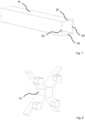
- the Figure 6A shows a surgical robot with four bendable robot arms according to the disclosure.
- the four proximal arm segments 1a, 1b, 1c, 1d of the robot arms are arranged in an enveloping housing 19 over the majority of their respective longitudinal extent.
- the distal arm segments 2a, 2b, 2c, 2d with the fixed segments 3a, 3b, 3c, 3d and the flexible arm segments 4a, 4b, 4c, 4d are arranged outside of the housing 19 and can move during an operation with the surgical robot.
- the Figure 6C Figure 12 shows the surgical robot from a proximal end perspective.
- the proximal end of the surgical robot can be connected to other components to actuate the robot arms, in particular to a drive unit with actuators for driving the various degrees of freedom of the robot arms.
- the surgical robot is a robot that can be mounted in the body of a patient.
- the bendable robot arms are introduced individually into the patient's body and only then connected to one another in the housing 19 to form the surgical robot.
- the 7 12 is a detailed view of the housing 19 of the surgical robot. It can be seen here that the housing 19 has cutouts 20 at a distal end, which are used for mounting the surgical robot, as explained in detail below.
- the 8 Fig. 1 shows a sealing fixing element 21 which is inserted into a proximal end of the housing after arranging several robotic arms in the housing 19 in order to correctly position the robotic arms in the housing in relation to one another and to fix them in this position.
- the fixing element 21 has a sealing effect. This can be avoided in particular be that during use, ie during an operation, insufflation gas escapes from the patient's abdominal cavity between the robot arms through the housing 19 .
- the fixing element 21 can be provided with a rubber coating for sealing.
- FIGS Figures 9A to 9G an assembly process of the surgical robot is shown.
- the robot arms are introduced into the distal end of the housing 19 one after the other.
- the first robot arm is inserted centrally into the housing 19 and then moved to the edge of the housing 19.
- the other robot arms can also be inserted into the housing 19 and moved to the edge of the housing 18 .
- Inserting the fourth robotic arm requires a twist to insert it through the cavity between the three already inserted robotic arms and then move it to the edge of the housing 19. This is shown in FIGS Figures 9C and 9D recognizable in detail.
- the robot arms are rearranged in the housing 19, as shown in FIGS Figures 9E and 9F shown so that each of the robotic arms is located in an associated assembled position.
- the respective connection formation 7 of the robot arm in question is pushed over the edge of the housing 19, whereby the robot arm is connected to the edge of the housing.
- the respective connection formations 7 are slid into the associated recesses 20, whereby the robotic arms are fixed in their mounted position at the distal end of the housing 19.
- the robotic arms can be miniaturized in such a way that they can be inserted directly into the housing 19 in their final arrangement.
- the rearranging step in assembly can be omitted.
- the sealing fixing element 21 is arranged in the proximal end of the housing 19, as in FIG Figure 9G shown where the Figure 9G represents a view of the distal end of the housing 19, so that the fixing element 21 is shown partially covered.
- the fixing element both fixes the robot arms in their mounted arrangement on the proximal end of the housing 19 and also maintains insufflation during an operation by means of the seal.
- a surgical robot may be provided that is not mountable in a patient's body.
- the robot arms can be arranged on arms of robots known as such, which also remain completely outside the patient during an operation and provide additional degrees of freedom.
- FIGS 10A and 10B an embodiment of a bendable robot arm for minimally invasive surgery is shown in different states of movement.
- the fixed segment 3 is angled at an approximately right angle relative to the proximal arm segment 1 .
- the toothed rack element 12 has been pushed far forward.
- the flexible arm segment 4 is strongly curved.
- the distal end of the robotic arm holds a weight.
- the fixed segment 3 is angled at a significantly smaller angle relative to the proximal segment and the flexible arm segment 4 is bent to a lesser extent.
- the structure of the robot arm and the forms of movement corresponded to the representations of the Figures 10A and 10B , wherein the proximal arm segment 1, the fixed segment 3 and the rack element 12 were produced by means of 3D printing.
- the robotic arm consists of a proximal arm segment, a distal arm segment with a fixed segment, a screw connection, a rack and a flexible arm segment.
- a pinion is integrated into the distal arm segment.
- the teeth of the rack and the teeth of the pinion mesh.
- the toothed rack is guided by means of a guide channel.
- the flexible arm segment consists of disks.
- the discs have two functions: they ensure radial spacing between individual NiTi wires, and by attaching all wires to the end of the flexible arm segment, a bend can be achieved.
- An end disk is attached to each NiTi wire on both sides.
- the angle adjustment unit showed a high level of functionality.
- the weakest point turned out to be the NiTi wires.
- the gearing between rack and pinion was flawless at all times.
- the angle adjustment mechanism was subjected to double the stress from bending the NiTi wires as well as lifting a load with a mass of 30 g and the teeth are relatively flat with a height of approx. 1.5 mm, the power transmission was at all times given.
- the minimum clearance between the pinion teeth and rack teeth was sufficient to ensure smooth movement.
- Position-independent stability of the toothed rack was achieved through the use of guide rails.
Abstract
Gemäß der Offenbarung ist ein abwinkelbarer Roboterarm für die minimal-invasive Chirurgie geschaffen. Der Roboterarm weist ein proximales Armsegment (1), welches sich entlang einer Längsachse des Roboterarms erstreckt, und ein distales Armsegment (2) auf, welches mit dem proximalen Armsegment (1) um eine zu der Längsachse orthogonale Schwenkachse schwenkbar verbunden ist. Das distale Armsegment (2) weist ein Ritzelsegment auf, welches mit in Form eines Ritzels um die Schwenkachse angeordneten Ritzelzähnen gebildet ist. Ein Zahnstangenelement (12) ist an dem proximalen Armsegment (1) derart angeordnet, dass das Zahnstangenelement (12) in Längsrichtung des Zahnstangenelements (12) parallel zu der Längsachse mittels einer Translation beweglich ist und an dem Zahnstangenelement (12) gebildete Stangenzähne mit den Ritzelzähnen in Eingriff stehen, so dass eine Bewegung des Zahnstangenelements (12) in der Längsrichtung über die Stangenzähne und die Ritzelzähne in eine Rotationsbewegung des distalen Armsegments (2) um die Schwenkachse gewandelt wird und das distale Armsegment (2) relativ zu dem proximalen Armsegment (1) um die Schwenkachse verschwenkt. Weiterhin sind ein Verfahren zum Herstellen eines abwinkelbaren Roboterarms sowie ein Chirurgieroboter bereitgestellt.According to the disclosure, an articulated robotic arm for minimally invasive surgery is provided. The robot arm has a proximal arm segment (1) which extends along a longitudinal axis of the robot arm and a distal arm segment (2) which is pivotally connected to the proximal arm segment (1) about a pivot axis orthogonal to the longitudinal axis. The distal arm segment (2) has a pinion segment which is formed with pinion teeth arranged in the form of a pinion around the pivot axis. A rack element (12) is arranged on the proximal arm segment (1) in such a way that the rack element (12) is movable in the longitudinal direction of the rack element (12) parallel to the longitudinal axis by means of translation and rack teeth formed on the rack element (12) with the pinion teeth are engaged so that movement of the rack member (12) in the longitudinal direction is converted via the rack teeth and the pinion teeth into rotational movement of the arm distal segment (2) about the pivot axis and the arm distal segment (2) relative to the arm proximal segment (1 ) pivoted about the pivot axis. Furthermore, a method for producing a bendable robot arm and a surgical robot are provided.
Description
Die Erfindung betrifft einen abwinkelbaren Roboterarm für die minimal-invasive Chirurgie, einen Chirurgieroboter sowie ein Verfahren zum Herstellen eines abwinkelbaren Roboterarms.The invention relates to a bendable robot arm for minimally invasive surgery, a surgical robot and a method for producing a bendable robot arm.
Im Bereich der Chirurgie kommen zunehmend Roboter zum Einsatz. Hierbei kann es sich um sogenannte Telemanipulatoren handeln, bei welchen robotische Systeme eine durch eine die Operation durchführende Person vorgegebene Bewegung direkt ausführen. Alternativ können Roboter im engeren Sinne eingesetzt werden, welche Bewegung zumindest teilautonom aufgrund vorheriger Vorgaben durch einen Nutzer und / oder von Sensordaten ausführen.Robots are increasingly being used in the field of surgery. These can be so-called telemanipulators, in which robotic systems directly execute a movement specified by a person performing the operation. Alternatively, robots in the narrower sense can be used, which execute movements at least partially autonomously based on previous specifications by a user and/or sensor data.
Insbesondere werden Chirurgieroboter in der minimal-invasiven Chirurgie (MIC bzw. minimally invasive surgery, MIS) eingesetzt, bei welcher der Zugang zum Operationssitus über kleine Einschnitte und / oder natürliche Körperöffnungen erfolgt. Hierbei können Chirurgieroboter dazu dienen, eine durch beengte Zugänge eingeschränkte Beweglichkeit einer operierenden Person zumindest teilweise zu kompensieren. Dies ist insbesondere bei sogenannten Single-Port-Eingriffen von Bedeutung, bei denen der Zugang zum Operationssitus über einen einzigen Zugang erfolgt. So wird bei der Single-Port-Laparoskopie (SPL) ein einziger Schnitt durch den Bauchnabel gesetzt, um durch diesen alle für die Operation benötigten Instrumente in die Bauchhöhle einzuführen.In particular, surgical robots are used in minimally invasive surgery (MIC or minimally invasive surgery, MIS), in which access to the operation site is via small incisions and/or natural body openings. Surgical robots can be used here to at least partially compensate for mobility of an operating person that is restricted due to cramped access. This is particularly important in the case of so-called single-port interventions, in which access to the surgical site is via a single port. With single-port laparoscopy (SPL), a single incision is made through the navel in order to insert all the instruments required for the operation into the abdominal cavity.
Bei Roboterarmen für Chirurgieroboter kann unterschieden werden zwischen diskreten und flexiblen Roboterstrukturen. Während diskrete Roboter auf hintereinandergeschalteten Gelenken beruhen, die durch starre Verbindungen miteinander verbunden sind, sind mit flexiblen Robotern kontinuierliche Krümmungen möglich, beispielsweise durch einen gekrümmten Draht.With robot arms for surgical robots, a distinction can be made between discrete and flexible robot structures. While discrete robots are based on cascaded joints connected by rigid connections, flexible robots allow for continuous curvatures, such as a curved wire.
Bei seriellen Abfolgen von Gelenken und starren Verbindungen im Sinne einer diskreten Roboterstruktur ist es beispielsweise bekannt, eine Winkelverstellung durch Drähte zu erreichen, welche zur Übertragung von Zug- und ggf. Schubkräften genutzt werden, um die Gelenke rotieren lassen, vgl. beispielsweise
Bei flexiblen Robotern hat sich insbesondere die Aktuation mit NiTi-Drähten durchgesetzt. Beispielsweise können über solche Drähte Klappen an Roboterarmen geöffnet werden, welche Instrumente bzw. Instrumentenarme ablenken (vgl.
Bei einem Konzept mit einer Vielzahl an Segmenten (beispielsweise gemäß
Eine weitere Möglichkeit, Winkel bei flexiblen Robotern einzustellen, ist die Verwendung von Kammern, die mit einem Fluid befüllt werden können (z.B. kompressierte Luft oder Wasser). Ein solches Konzept ist beispielsweise bekannt aus
In robotischen Systemen ist verbreitet eine Wandlung von Linear- in Rotationsbewegungen oder umgekehrt erforderlich. Hierbei ist es bekannt, für die Erzeugung einer Linear Bewegung aus einer Rotationsbewegung Zahnstangen-Ritzel-Paarungen einzusetzen, in denen das Ritzel, welches auf einer Motorwelle montiert ist, die Zahnstange antreibt, um eine Linearbewegung zu erzielen. Dabei können eine hohe Laufruhe, Positioniergenauigkeit und Vorschubkraft erzielt werden. Bei Maschinen (beispielweise Baumaschinen, Werkzeugmaschinen, Biegemaschinen, Formträgern, Gießerei-, Bergbau-, Land- und Verpackungsmaschinen), die eine Linearbewegung mit großer Kraft bereitstellen, insbesondere mittels Öldruck, sind Kolbendrehantriebe bekannt, bei denen Öldruck das Verschieben von Zahnstangen bewirkt, wobei die Linearbewegung der Zahnstangen über eine Verzahnung in eine Drehbewegung des Ritzels umgewandelt wird.In robotic systems, a conversion from linear to rotary movements or vice versa is often required. Here, it is known to use rack and pinion pairings for generating a linear movement from a rotational movement, in which the pinion, which is mounted on a motor shaft, drives the rack in order to achieve a linear movement. A high level of smooth running, positioning accuracy and feed force can be achieved. In machines (e.g. construction machinery, machine tools, bending machines, mold carriers, foundry, mining, agricultural and packaging machines) that provide a linear movement with great force, in particular by means of oil pressure, rotary piston drives are known in which oil pressure causes the racks to be displaced, whereby the linear movement of the toothed racks is converted into a rotary movement of the pinion via a gearing.
Aus dem Dokument
Das Dokument
Aufgabe der Erfindung ist es, verbesserte Technologien für Chirurgieroboter mit abwinkelbaren Roboterarmen anzugeben, bei denen insbesondere eine mechanische Komplexität gering ist und ein effizienter Betrieb gewährleistet ist.The object of the invention is to specify improved technologies for surgical robots with robot arms that can be bent, in which, in particular, mechanical complexity is low and efficient operation is ensured.
Die Aufgabe wird gelöst durch einen abwinkelbaren Roboterarm nach dem unabhängigen Anspruch 1 sowie einen Chirurgieroboter und ein Verfahren zum Herstellen eines abwinkelbaren Roboterarms nach weiteren unabhängigen Ansprüchen. Ausgestaltungen sind Gegenstand von abhängigen Ansprüchen.The object is achieved by a bendable robot arm according to
Gemäß einem Aspekt ist ein abwinkelbarer Roboterarm für die minimal-invasive Chirurgie geschaffen. Der abwinkelbare Roboterarm weist ein proximales Armsegment, welches sich entlang einer Längsachse des Roboterarms erstreckt, und ein distales Armsegment auf, welches mit dem proximalen Armsegment um eine zu der Längsachse orthogonale Schwenkachse schwenkbar verbunden ist. Das distale Armsegment weist ein Ritzelsegment auf, welches mit in Form eines Ritzels um die Schwenkachse angeordneten Ritzelzähnen gebildet ist. Ein Zahnstangenelement ist an dem proximalen Armsegment derart angeordnet, dass das Zahnstangenelement in Längsrichtung des Zahnstangenelements parallel zu der Längsachse mittels einer Translation beweglich ist, und an dem Zahnstangenelement gebildete Stangenzähne mit den Ritzelzähnen in Eingriff stehen, so dass eine Bewegung des Zahnstangenelements in der Längsrichtung über die Stangenzähne und die Ritzelzähne in eine Rotationsbewegung des distalen Armsegments um die Schwenkachse gewandelt wird und das distale Armsegment relativ zu dem proximalen Armsegment um die Schwenkachse verschwenkt.According to one aspect, an articulated robotic arm for minimally invasive surgery is provided. The bendable robot arm has a proximal arm segment, which extends along a longitudinal axis of the robot arm, and a distal arm segment, which is pivotally connected to the proximal arm segment about a pivot axis orthogonal to the longitudinal axis. The distal arm segment includes a pinion segment formed with pinion teeth arranged in the shape of a pinion about the pivot axis. A rack member is disposed on the proximal arm segment such that the rack member is translationally movable longitudinally of the rack member parallel to the longitudinal axis, and rack teeth formed on the rack member mesh with the pinion teeth such that longitudinal movement of the rack member is via converting the rack teeth and the pinion teeth into rotational movement of the arm distal segment about the pivot axis; and pivoting the arm distal segment relative to the arm proximal segment about the pivot axis.
Gemäß einem weiteren Aspekt ist ein Chirurgieroboter bereitgestellt, insbesondere für die minimal-invasive Chirurgie, der einen abwinkelbaren Roboterarm gemäß der Offenbarung aufweist.According to a further aspect, a surgical robot is provided, in particular for minimally invasive surgery, which has a bendable robot arm according to the disclosure.
Nach noch einem Aspekt ist ein Verfahren zum Herstellen eines abwinkelbaren Roboterarms geschaffen. Das Verfahren umfasst die Schritte des Bereitstellens eines proximalen Armsegments, dessen Erstreckungsrichtung eine Längsachse des Roboterarms definiert, des Bereitstellens eines distalen Armsegments mit einem Ritzelsegment, welches mit in Form eines Ritzels um eine Schwenkachse angeordneten Ritzelzähnen gebildet ist, des Verbindens des distalen Armsegments mit dem proximalen Armsegment, derart, dass das distale Armsegment um die Schwenkachse relativ zu dem proximalen Armsegment schwenkbar ist und die Schwenkachse zu der Längsachse orthogonal verläuft, und des Anordnen eines Zahnstangenelements an dem proximalen Armsegment. Das Zahnstangenelement wird an dem proximalen Armsegment derart angeordnet, dass das Zahnstangenelement in Längsrichtung des Zahnstangenelements parallel zu der Längsachse mittels einer Translation beweglich ist, und an dem Zahnstangenelement gebildete Stangenzähne mit den Ritzelzähnen in Eingriff stehen, so dass eine Bewegung des Zahnstangenelements in der Längsrichtung über die Stangenzähne und die Ritzelzähne in eine Rotationsbewegung des distalen Armsegments um die Schwenkachse gewandelt wird und das distale Armsegment relativ zu dem proximalen Armsegment um die Schwenkachse verschwenkt.According to another aspect, a method for producing an articulated robot arm is provided. The method comprises the steps of providing a proximal arm segment, the direction of extension of which defines a longitudinal axis of the robot arm, providing a distal arm segment with a pinion segment which is formed with pinion teeth arranged in the form of a pinion about a pivot axis, connecting the distal arm segment to the proximal one Arm segment such that the distal arm segment is pivotable about the pivot axis relative to the proximal arm segment and the pivot axis is orthogonal to the longitudinal axis, and arranging a rack and pinion member on the proximal arm segment. The rack member is disposed on the proximal arm segment such that the rack member is translationally movable in the longitudinal direction of the rack member parallel to the longitudinal axis, and rack teeth formed on the rack member mesh with the pinion teeth so that longitudinal movement of the rack member is via converting the rack teeth and the pinion teeth into rotational movement of the arm distal segment about the pivot axis; and pivoting the arm distal segment relative to the arm proximal segment about the pivot axis.
Im Sinne der vorliegenden Offenbarung beziehen sich die Begriffe Roboter und Roboterarm sowohl auf Roboter im engeren Sinne, welche autonome oder teil-autonome Bewegungen ausführen, als auch auf Telemanipulationssysteme, bei denen robotische Arme eine direkt von einer bedienenden Person vorgegebene Bewegung ausführen. Begrifflich umfasst sind hierbei auch Kombinationen der beiden Konzepte.Within the meaning of the present disclosure, the terms robot and robot arm refer both to robots in the narrower sense, which perform autonomous or semi-autonomous movements, and to telemanipulation systems in which robotic arms perform a movement specified directly by an operator. Conceptually included here are also combinations of the two concepts.
Der Begriff proximal bezeichnet im Zusammenhang mit dem abwinkelbaren Roboterarm und dem Chirurgieroboter eine einem zentralen Hauptteil des Roboters zugewandte Richtung bzw. Anordnung. Der Begriff distal bezeichnet eine dem zentralen Hauptteil abgewandte und dem Operationssitus zugewandte Richtung bzw. Anordnung.In connection with the bendable robot arm and the surgical robot, the term proximal designates a direction or arrangement facing a central main part of the robot. The term distal designates a direction or arrangement facing away from the central main part and towards the operation site.
Überraschenderweise wurde festgestellt, dass mit einer Zahnstangen-Ritzel-Paarung gemäß den unabhängigen Ansprüchen, welche durch das Zahnstangenelement und das Ritzelsegment gebildet ist, eine ausreichende Stabilität und Kraftwirkung für die Verwendung in einem abwinkelbaren Roboterarm für die minimal-invasive Chirurgie bereitgestellt werden kann, während gleichzeitig eine für diese Anwendung geeignete Dimensionierung der Komponenten vorgesehen ist. Demgegenüber entspricht es dem Stand der Technik, beispielsweise gemäß den oben genannten Dokumenten
Die Ritzelzähne können als Ausformungen des distalen Armsegments gebildet sein. In diesem Fall bildet das Ritzelsegment einen Abschnitt des distalen Armsegments. Beispielsweise können die Ritzelzähne mittels eines additiven Verfahrens, insbesondere 3D-Druck, zusammen mit dem distalen Armsegement hergestellt werden, die Ritzelzähne können an das distale Armsegment angeformt sein oder die Ritzelzähne können aus dem distalen Armsegment herausgeformt sein, zum Beispiel mittels spanender Bearbeitung wie Fräsen oder durch Stanzen oder Schneiden, zum Beispiel Laser- oder Wasserstrahlschneiden. Durch eine Bildung der Ritzelzähne als Ausformungen des distalen Armsegments können die Anzahl benötigter Verbindungselemente sowie hiermit verbunden Materialkosten und Montagezeit reduziert sein.The pinion teeth can be formed as formations of the distal arm segment. In this case the pinion segment forms a portion of the distal arm segment. For example, the pinion teeth can be produced together with the distal arm segment by means of an additive process, in particular 3D printing, the pinion teeth can be molded onto the distal arm segment or the pinion teeth can be formed out of the distal arm segment, for example by means of machining such as milling or by punching or cutting, for example laser or water jet cutting. Forming the pinion teeth as formations of the distal arm segment can reduce the number of connecting elements required and the associated material costs and assembly time.
Alternativ können die Ritzelzähne separat hergestellt und an dem distalen Armsegment befestigt sein, beispielsweise mittels Kleben, Schweißen, Löten, Schrauben oder Nieten. Hierbei bildet das Ritzelsegment ein separates Element, das an dem distalen Armsegment angeordnet und an diesem befestigt ist. Insbesondere kann ein Ritzel oder ein Abschnitt eines Ritzels (insbesondere in Form eines Kreissegments mit Zähnen entlang des Umfangs) an dem distalen Armsegment angeordnet und fest mit diesem verbunden sein. Hierdurch kann die Verwendung von Standardbauteilen ermöglicht sein, wodurch die Herstellungskosten reduziert sein können.Alternatively, the pinion teeth may be manufactured separately and attached to the distal arm segment, such as by gluing, welding, brazing, screws or rivets. Here, the pinion segment forms a separate element which is arranged on and attached to the distal arm segment. In particular, a pinion or a portion of a pinion (in particular in the form of a circular segment with teeth along the circumference) can be arranged on the distal arm segment and firmly connected to it. As a result, the use of standard components can be made possible, as a result of which the manufacturing costs can be reduced.
Die Ritzelzähne können sich um die Schwenkachse über einen begrenzten Winkelbereich erstrecken. Insbesondere kann hierdurch an dem distalen Armsegment mit dem Ritzelsegment ein Abschnitt eines Ritzels gebildet und / oder angeordnet sein. Der begrenzte Winkelbereich kann einem Bewegungsradius der Abwinklung des Roboterarms entsprechen. Beispielsweise können die Ritzelzähne einen Winkel zwischen einer vollständigen Streckung des distalen Armsegments gegenüber dem proximalen Armsegment (entsprechend 0°) und einem rechten Winkel zwischen proximalem Armsegment und distalem Armsegment (90°) umspannen.The pinion teeth may extend about the pivot axis over a limited angular range. In this way, in particular, a section of a pinion can be formed and/or arranged on the distal arm segment with the pinion segment. The limited angular range can correspond to a radius of movement of the bending of the robot arm. For example, the pinion teeth can span an angle between full extension of the distal arm segment relative to the proximal arm segment (corresponding to 0°) and a right angle between the proximal arm segment and the distal arm segment (90°).
Das distale Armsegment kann ein zweites Ritzelsegment mit um die Schwenkachse angeordneten Ritzelzähnen aufweisen, welches von dem Ritzelsegment entlang der Schwenkachse beabstandet an dem distalen Armsegment angeordnet ist. Insbesondere können die Ritzelsegmente an sich entlang einer durch die Schwenkachse vorgegebenen Richtung gegenüberliegenden Seiten des distalen Armsegments angeordnet sein. Hierbei stehen Stangenzähne mit beiden Ritzelsegmenten in Eingriff, um das distale Armsegment zu verschwenken. Durch das Bereitstellen eines zweiten Ritzelsegments, insbesondere an gegenüberliegenden Seiten des distalen Armsegments, kann ein Verklemmen und / oder Verkanten des Abwinkelmechanismus verhindert oder reduziert sein. Weiterhin kann mit einer Ausführung mit einem zweiten Ritzelsegment ein Sicherheitsmechanismus bereitgestellt sein, der nach einem eventuellen Zahnbruch eines der Ritzelsegmente das sichere Anlegen und Entfernen des Roboters durch das verbleibende, noch intakte Ritzelsegment ermöglicht.The distal arm segment may include a second pinion segment having pinion teeth disposed about the pivot axis and spaced from the pinion segment along the pivot axis on the distal arm segment. In particular, the pinion segments can be arranged along opposite sides of the distal arm segment along a direction predetermined by the pivot axis. Here, rack teeth engage both pinion segments to pivot the arm distal segment. By providing a second pinion segment, in particular on opposite sides of the distal arm segment, jamming and/or canting of the bending mechanism can be prevented or reduced. Furthermore, with an embodiment having a second pinion segment, a safety mechanism can be provided which, after a possible tooth breakage of one of the pinion segments, enables the robot to be put on and removed safely using the remaining, still intact pinion segment.
Das Zahnstangenelement kann zwei Sätze von Stangenzähnen aufweisen, wobei die zwei Sätze von Stangenzähnen parallel und in Richtung der Schwenkachse beabstandet zueinander angeordnet sind, derart, dass der erste Satz von Stangenzähnen mit den Ritzelzähnen des Ritzelsegments in Eingriff steht und der zweite Satz von Stangenzähnen mit den Ritzelzähnen des zweiten Ritzelsegments in Eingriff steht.The rack member may have two sets of rack teeth, the two sets of rack teeth being parallel and spaced apart in the direction of the pivot axis such that the first set of rack teeth meshes with the pinion teeth of the pinion segment and the second set of rack teeth meshes with the Pinion teeth of the second pinion segment is engaged.
Alternativ kann für Ausführungen mit einem zweiten Ritzelsegment vorgesehen sein, dass das Zahnstangenelement lediglich einen Satz von Stangenzähnen aufweist, wobei die Stangenzähne so breit ausgeführt sind, dass sie mit beiden Ritzelsegmenten in Eingriff stehen, um das distale Armsegment zu verschwenken.Alternatively, for embodiments with a second pinion segment, provision can be made for the rack element to have only one set of rack teeth, with the rack teeth being designed so wide that they engage with both pinion segments in order to pivot the distal arm segment.
Das Zahnstangenelement kann mit einem proximalen Zahnstangensegment und einem in der Längsrichtung an das proximale Zahnstangensegment anschließendem distalen Zahnstangensegment gebildet sein, wobei das distale Zahnstangesegment in Richtung der Schwenkachse breiter ist als das proximale Zahnstangensegment. Hierbei können die Stangenzähne im Bereich des distalen Zahnstangenelements angeordnet sein. Das proximale Zahnstangesegment kann frei von Stangenzähnen sein. Bei Ausführungen mit zwei Sätzen von Stangenzähnen können die Sätze von Stangenzähnen parallel und in Richtung der Schwenkachse beabstandet zueinander an dem distalen Zahnstangensegment angeordnet sein.The rack member may be formed with a proximal rack segment and a distal rack segment longitudinally adjoining the proximal rack segment, the distal rack segment being wider than the proximal rack segment in the direction of the pivot axis. Here, the rack teeth can be arranged in the area of the distal toothed rack element. The proximal rack segment may be free of rack teeth. In embodiments having two sets of rack teeth, the sets of rack teeth may be parallel and spaced apart in the direction of the pivot axis on the distal rack segment.
Das proximale Armsegment kann einen entlang der Längsachse verlaufenden Führungskanal aufweisen, in welchem das Zahnstangenelement, insbesondere mit einem proximalen Zahnstangensegment, zumindest abschnittsweise angeordnet und geführt ist. Beispielsweise kann der Führungskanal im Querschnitt eine V-Form oder U-Form aufweisen. Der Führungskanal kann sich über die gesamte Länge des proximalen Armsegments erstrecken. Alternativ kann sich der Führungskanal nur teilweise entlang des proximalen Armsegments erstrecken, wobei die Länge des Führungskanals mindestens einer Länge entspricht, um welche das Zahnstangenelement für eine maximale Abwinklung des distalen Armsegments parallel zu der Längsachse bewegbar ist. In diesem Fall kann das Zahnstangenelement ein vorstehendes Führungselement aufweisen welches in dem Führungskanal angeordnet und in diesem linear geführt ist.The proximal arm segment can have a guide channel running along the longitudinal axis, in which the rack element, in particular with a proximal rack segment, is arranged and guided at least in sections. For example, can the guide channel have a V-shape or U-shape in cross section. The guide channel can extend the entire length of the proximal arm segment. Alternatively, the guide channel can extend only partially along the proximal arm segment, the length of the guide channel corresponding to at least a length by which the toothed rack element can be moved parallel to the longitudinal axis for maximum angling of the distal arm segment. In this case, the toothed rack element can have a projecting guide element which is arranged in the guide channel and is linearly guided in it.
Zusätzlich oder alternativ zu einem Führungskanal des proximalen Armsegments kann das proximale Armsegment ein Armsegment-Führungselement aufweisen, welches vorzugsweise an einem distalen Ende des proximalen Armsegments in der Längsrichtung vorspringend angeordnet ist, insbesondere einstückig an das proximale Armsegment angeformt oder als separates Element gebildet und an dem proximalen Armsegment befestigt ist. Das Armsegment-Führungselement kann als Führungsstab ausgebildet sein. In einer Ausführung des abwinkelbaren Roboterarms mit Armsegment-Führungselement weist das Zahnstangenelement einen Zahnstangenelement-Führungskanal auf in welchem das Armsegment-Führungselement zumindest abschnittsweise angeordnet und geführt ist. Der Zahnstangenelement-Führungskanal kann auf einer den Stangenzähnen gegenüberliegenden Seite des Zahnstangenelements angeordnet sein, insbesondere an einer den Stangenzähnen gegenüberliegenden Seite des distalen Zahnstangenelements. Das Armsegment-Führungselement und der Zahnstangenelement-Führungskanal weisen vorzugsweise einen nicht-runden Querschnitt auf, insbesondere einen rechteckigen Querschnitt.In addition or as an alternative to a guide channel of the proximal arm segment, the proximal arm segment can have an arm segment guide element, which is preferably arranged on a distal end of the proximal arm segment so as to protrude in the longitudinal direction, in particular formed in one piece on the proximal arm segment or formed as a separate element and on which attached to the proximal arm segment. The arm segment guide element can be designed as a guide rod. In one embodiment of the bendable robot arm with an arm segment guide element, the toothed rack element has a toothed rack element guide channel in which the arm segment guide element is arranged and guided at least in sections. The rack member guide channel may be located on a side of the rack member opposite the rack teeth, particularly on a side of the distal rack member opposite the rack teeth. The arm segment guide element and the rack element guide channel preferably have a non-round cross section, in particular a rectangular cross section.
Durch eine Führung der Relativbewegung zwischen dem proximalen Armsegment und dem Zahnstangenelement mittels des Führungskanals und / oder des Zahnstangenelement-Führungskanals können eine sichere Führung und ein ruhiger Lauf gewährleistet sein, insbesondere dadurch, dass Seitenwände des Führungskanals und / oder des Zahnstangenelement-Führungskanals das Zahnstangenelement bzw. das Armsegment-Führungselement umgreifen. Durch eine Führung im Bereich der bzw. in geringer Entfernung zu den Stangenzähnen können wirkende Radialkräfte und / oder Tangentialkräfte der Zahnstangen-Ritzel-Paarung des abwinkelbaren Roboterarms in den Elementen der Führung aufgenommen werden, wodurch insbesondere ein auf das Zahnstangenelement wirkendes Biegemoment reduziert sein kann. Somit kann eine mechanische Belastung des Zahnstangenelements reduziert sein.By guiding the relative movement between the proximal arm segment and the rack element by means of the guide channel and/or the rack element guide channel, reliable guidance and smooth running can be ensured, in particular because side walls of the guide channel and/or the rack element guide channel cover the rack element or .Grasp the arm segment guide element. By guiding in the area of or at a short distance from the rod teeth, acting radial forces and/or tangential forces of the rack-pinion pairing of the articulated robot arm can be absorbed in the elements of the guide, which in particular can reduce a bending moment acting on the rack element. A mechanical load on the toothed rack element can thus be reduced.
Das distale Armsegment kann zumindest abschnittsweise als flexibles Armsegment gebildet sein, welches entlang seiner Längserstreckung kontinuierlich oder quasi-kontinuierlich abwinkelbar ist. Hierbei kann das distale Armsegment distal eines Bereichs, in dem das Ritzelsegment angeordnet ist gemäß einer flexiblen Roboterstruktur ausgebildet sein, beispielsweise gemäß den Prinzipien flexibler Roboterstrukturen, welche als solche aus dem Stand der Technik bekannt sind, oder gemäß von dem Stand der Technik abweichenden flexiblen Roboterstrukturen.The distal arm segment can be formed, at least in sections, as a flexible arm segment which can be bent continuously or quasi-continuously along its length. Here, the distal arm segment can be formed distally of a region in which the pinion segment is arranged according to a flexible robot structure, for example according to the principles of flexible robot structures, which are known as such from the prior art, or according to flexible robot structures deviating from the prior art .
In einer bevorzugten Ausführung kann das flexible Armsegment mit mindestens drei Zug-Schub-Mitteln gebildet sein, welche entlang einer Längserstreckung des flexiblen Armsegments parallel und entlang der Längserstreckung verschiebbar zueinander angeordnet sind. Jedem Zug-Schub-Mittel kann ein entsprechender Linearaktor zugeordnet sein, welcher eingerichtet ist das betreffende Zug-Schub-Mittel entlang der Längserstreckung des flexiblen Armsegments zu verschieben. Hierbei können die entsprechenden Linearaktoren Teil des abwinkelbaren Roboterarms sein, oder die betreffenden Zug-Schub-Mittel können eingerichtet sein, mit einem entsprechenden Linearaktor funktionsverbunden zu werden, welcher außerhalb des abwinkelbaren Roboterarms angeordnet ist, beispielsweise als Teil eine Chirurgieroboters, welchem der abwinkelbare Roboterarm zugeordnet ist. Ein Linearaktor kann ein Aktor sein, der direkt eine Linearbewegung bereitstellt oder ein Aktor, der eine andere Bewegungsform bereitstellt, beispielsweise eine Rotation, in Verbindung mit einer Mechanik, welche die von dem Aktor bereitgestellte Bewegung in eine Linearbewegung wandelt.In a preferred embodiment, the flexible arm segment can be formed with at least three pull-push means, which are arranged parallel to one another along a longitudinal extent of the flexible arm segment and can be displaced along the longitudinal extent. Each pull-push device can be assigned a corresponding linear actuator, which is set up to move the relevant pull-push device along the longitudinal extension of the flexible arm segment. In this case, the corresponding linear actuators can be part of the bendable robot arm, or the relevant pull-push means can be set up to be functionally connected to a corresponding linear actuator, which is arranged outside of the bendable robot arm, for example as part of a surgical robot to which the bendable robot arm is assigned is. A linear actuator can be an actuator that provides a linear movement directly or an actuator that provides another form of movement, for example rotation, in conjunction with a mechanism that converts the movement provided by the actuator into a linear movement.
Bei den Zug-Schub-Mitteln kann es sich um Drähte handeln, insbesondere NiTi-Drähte, also Drähte aus einer Nickel-Titan-Legierung. Die Drähte können eine ausreichend hohe Knicksteifigkeit aufweisen, um als Zug-Schub-Mittel sowohl in einem Zug- als auch in einem Schub-Modus zum Einsatz zu kommen. Bei einer Abwinklung bzw. Biegung des flexiblen Armsegments kann die Länge eines bezogen auf den Querschnitt des flexiblen Armsegments zentral angeordneten Zug-Schub-Mittels konstant bleiben, der entsprechende Linearaktor kann sich also nicht bewegen, während einer oder mehrere der verbleibenden Zug-Schub-Mittel bewegt, also entlang der Längserstreckung des flexiblen Armsegments verschoben, werden.The pull-push means can be wires, in particular NiTi wires, ie wires made from a nickel-titanium alloy. The wires can have a sufficiently high buckling stiffness to be used as a push-pull device in both a pull and a push mode. When the flexible arm segment bends or bends, the length of a pull-push device that is arranged centrally in relation to the cross section of the flexible arm segment can remain constant, i.e. the corresponding linear actuator cannot move while one or more of the remaining pull-push devices moved, ie shifted along the length of the flexible arm segment.
Gemäß einer bevorzugten Ausführung kann das flexible Armsegment mit mindestens fünf Zug-Schub-Mitteln gebildet sein, wobei die oben ausgeführten Ausgestaltungen bezüglich der Zug-Schub-Mittel entsprechend vorgesehen sein können. Insbesondere kann bei einer Abwinklung bzw. Biegung des flexiblen Armsegments die Länge eines bezogen auf den Querschnitt des flexiblen Armsegments zentral angeordneten Zug-Schub-Mittels konstant bleiben, während einer oder mehrere der verbleibenden Zug-Schub-Mittel bewegt, also entlang der Längserstreckung des flexiblen Armsegments verschoben, werden. Hierbei können zwei der nicht-zentralen Zug-Schub-Mittel antagonistisch aktuiert werden, so dass das eine Zug-Schub-Mittel in eine distale Richtung geschoben wird, während das andere Zug-Schub-Mittel auf einer bezogen auf das zentrale Zug-Schub-Mittel gegenüberliegenden Seite in eine proximale Richtung gezogen wird, so dass eine Biegung des flexiblen Armsegments erreicht wird.According to a preferred embodiment, the flexible arm segment can be formed with at least five pull-push means, it being possible for the configurations explained above with regard to the pull-push means to be provided accordingly. In particular, with an angling or bending of the flexible arm segment, the length of a relative to the cross section of the flexible arm segment centrally arranged pull-push means remain constant, while one or more of the remaining pull-push means moves, so along the longitudinal extent of the flexible arm segment, are shifted. Here, two of the non-central pull-push means can be actuated antagonistically, so that one pull-push means is pushed in a distal direction, while the other pull-push means is in a direction related to the central pull-push Mean opposite side is pulled in a proximal direction, so that a bending of the flexible arm segment is achieved.
Bei einer Ausführung des distalen Armsegments zumindest abschnittsweise als flexibles Armsegment kann das distale Armsegment mit einem festen Segment gebildet sein, welches mit dem proximalen Armsegment um die Schwenkachse schwenkbar verbunden ist und welches das Ritzelsegment aufweist, wobei sich das flexible Armsegment direkt oder mittelbar an das feste Segment anschließt. Hierbei können insbesondere Zug-Schub-Elemente des flexiblen Armsegments durch das proximale Armsegment und das feste Segment des distalen Armsegments geführt sein. Das feste Segment kann Element-Führungskanäle für die Führung der Zug-Schub-Elemente aufweisen. Mittels der Element-Führungskanäle kann eine unterschiedliche Verteilung der Zug-Schub-Elemente in dem distalen Armsegment gegenüber dem proximalen Armsegment erreicht sein. Beispielsweise kann vorgesehen sein, dass die Zug-Schub-Elemente in dem proximalen Armsegment direkt linear nebeneinander angeordnet geführt sind, während sie entlang des distalen Armsegment einem flexiblen Armsegment entsprechend angeordnet sind, insbesondere kreisförmig um ein zentrales Zug-Schub-Element herum. Hierzu kann vorgesehen sein, dass eine Anordnung der Element-Führungskanäle einer Anordnung der Zug-Schub-Elemente in dem distalen Armsegment entspricht, so dass die Zug-Schub-Elemente vor dem Eintreten in die Element-Führungskanäle gegenüber ihrer Anordnung in dem proximalen Armsegment umgeordnet werden. Alternativ können die Element-Führungskanäle so ausgestaltet sein, dass sie eine Umordnung der Zug-Schub-Elemente direkt führen vorgeben. In diesem Fall entspricht die Anordnung von dem proximalen Armsegment zugewandten Eingängen der Element-Führungskanäle einer Anordnung der Zug-Schub-Elemente in dem proximalen Armsegment und eine Anordnung von dem proximalen Armsegment abgewandten Ausgängen der Element-Führungskanäle entspricht einer Anordnung der Zug-Schub-Elemente in dem distalen Armsegment.If the distal arm segment is designed at least in sections as a flexible arm segment, the distal arm segment can be formed with a fixed segment which is connected to the proximal arm segment so that it can pivot about the pivot axis and which has the pinion segment, with the flexible arm segment being attached directly or indirectly to the fixed segment connects. Here, in particular, pull-push elements of the flexible arm segment can be guided through the proximal arm segment and the fixed segment of the distal arm segment. The fixed segment can have element guide channels for guiding the push-pull elements. A different distribution of the push-pull elements in the distal arm segment compared to the proximal arm segment can be achieved by means of the element guide channels. For example, it can be provided that the pull-push elements are arranged linearly next to one another in the proximal arm segment, while they are arranged along the distal arm segment in accordance with a flexible arm segment, in particular in a circle around a central pull-push element. For this purpose, it can be provided that an arrangement of the element guide channels corresponds to an arrangement of the pull-push elements in the distal arm segment, so that the pull-push elements are rearranged before entering the element guide channels compared to their arrangement in the proximal arm segment become. Alternatively, the element guide channels can be designed in such a way that they prescribe a rearrangement of the push-pull elements to guide them directly. In this case, the arrangement of the inlets of the element guide channels facing the proximal arm segment corresponds to an arrangement of the pull-push elements in the proximal arm segment and an arrangement of the outlets of the element guide channels facing away from the proximal arm segment corresponds to an arrangement of the pull-push elements in the distal arm segment.
Alternativ oder zusätzlich zu einem flexiblen Armsegment kann das distale Armsegment zumindest abschnittsweise als diskret-robotisches Armsegment mit entlang seiner Längserstreckung hintereinander angeordneten Segmenten gebildet sein, wobei das diskret-robotische Armsegment entlang seiner Längserstreckung segmentweise abwinkelbar ist. Hierbei kann das diskret-robotische Armsegment distal eines Bereichs, in dem das Ritzelsegment angeordnet ist gemäß einer diskreten Roboterstruktur ausgebildet sein, beispielsweise gemäß den Prinzipien diskreter Roboterstrukturen, welche als solche aus dem Stand der Technik bekannt sind, oder gemäß von dem Stand der Technik abweichenden diskreten Roboterstrukturen. In Ausführungen, in denen das distale Armsegment sowohl wenigstens ein flexibles Armsegment als auch wenigstens ein diskret-robotisches Armsegment aufweist, können das flexible Armsegment und das diskret-robotische Armsegment entlang der Längserstreckung des distalen Armsegments in geeigneter Reihenfolge hintereinander angeordnet sein, wobei sowohl das flexible Armsegment als auch das diskret-robotische Armsegment distal eines Bereichs ausgebildet sind, in dem das Ritzelsegment angeordnet ist, insbesondere distal eine festen Segments des distalen Armsegments.As an alternative or in addition to a flexible arm segment, the distal arm segment can be formed at least in sections as a discrete robotic arm segment with segments arranged one behind the other along its length, the discrete robotic arm segment being able to be angled in segments along its length. Here can the discrete robotic arm segment distal to an area in which the pinion segment is arranged can be designed according to a discrete robot structure, for example according to the principles of discrete robot structures which are known as such from the prior art, or according to discrete robot structures deviating from the prior art . In embodiments in which the distal arm segment has both at least one flexible arm segment and at least one discrete robotic arm segment, the flexible arm segment and the discrete robotic arm segment can be arranged one behind the other in a suitable order along the longitudinal extent of the distal arm segment, with both the flexible Arm segment and the discrete-robotic arm segment are formed distally of an area in which the pinion segment is arranged, in particular distally of a fixed segment of the distal arm segment.
Der abwinkelbare Roboterarm kann einen Linearaktor aufweisen, welcher mit dem Zahnstangenelement verbunden und eingerichtet ist, das Zahnstangenelement parallel zu der Längsachse translatorisch vor- und zurückzubewegen. Alternativ hierzu kann das Zahnstangenelement eingerichtet sein, mit einem entsprechenden Linearaktor funktionsverbunden zu werden, welcher außerhalb des abwinkelbaren Roboterarms angeordnet ist, beispielsweise als Teil eine Chirurgieroboters, welchem der abwinkelbare Roboterarm zugeordnet ist. Ein Linearaktor kann hierbei ein Aktor sein, der direkt eine Linearbewegung bereitstellt oder ein Aktor, der eine andere Bewegungsform bereitstellt, beispielsweise eine Rotation, in Verbindung mit einer Mechanik, welche die von dem Aktor bereitgestellte Bewegung in eine Linearbewegung wandelt.The bendable robot arm can have a linear actuator which is connected to the rack element and is set up to move the rack element back and forth translationally parallel to the longitudinal axis. As an alternative to this, the toothed rack element can be set up to be functionally connected to a corresponding linear actuator which is arranged outside of the bendable robot arm, for example as part of a surgical robot to which the bendable robot arm is assigned. A linear actuator can be an actuator that provides a linear movement directly or an actuator that provides another form of movement, for example rotation, in conjunction with a mechanism that converts the movement provided by the actuator into a linear movement.
Das distale Armsegment kann mit dem proximalen Armsegment mittels einer Schraubenverbindung um die Schwenkachse schwenkbar verbunden sein. Alternativ oder zusätzlich kann eine andere Verbindungsart, beispielsweise eine Nietverbindung eine Verbindung über ein separates Gelenkbauteil oder eine direkte und rotatorisch bewegliche formschlüssige Verbindung zwischen dem distalen Armsegment und dem proximalen Armsegment vorgesehen sein. Das proximale Armsegment kann mit einer Verbindungs-Ausformung gebildet sein, welche sich zu dem distalen Armsegment erstreckt und mit diesem schwenkbar verbunden ist. Insbesondere kann vorgesehen sein, dass sich die Verbindungs-Ausformung zwischen zwei Ritzelsegmente des distalen Armsegments erstreckt und zwischen diesen schwenkbar fixiert wird. Hierbei können die Ritzelsegmente als Ausformungen von Flankenelementen des distalen Armsegments gebildet sein, und die Verbindungs-Ausformung kann sich zwischen die Flankenelemente erstrecken und zwischen diesen schwenkbar fixiert sein. Die Verbindungs-Ausformung kann einstückig mit dem proximalen Armsegment gebildet oder separat gebildet und an diesem fest angeordnet sein.The distal arm segment can be pivotally connected to the proximal arm segment by means of a screw connection about the pivot axis. Alternatively or additionally, another type of connection, for example a rivet connection, a connection via a separate joint component or a direct and rotationally movable form-fitting connection between the distal arm segment and the proximal arm segment can be provided. The proximal arm segment may be formed with a link formation which extends to and is pivotally connected to the distal arm segment. In particular, it can be provided that the connecting formation extends between two pinion segments of the distal arm segment and is pivotably fixed between them. Here, the pinion segments can be formed as formations of flank elements of the distal arm segment, and the connecting formation can extend between the flank elements and be pivotably fixed between them. The connector formation may be integrally formed with the proximal arm segment or may be separately formed and fixedly attached thereto.
Der Chirurgieroboter kann als im Körper eines Patienten montierbarer Roboter ausgebildet sein. Hierbei kann vorgesehen sein, einzelne Elemente des Chirurgieroboters, beispielsweise umfassend mehrere Roboterarme, separat in den Körper des Patienten einzubringen und im Körper des Patienten miteinander zu dem Chirurgieroboter zu verbinden. Bei einer Ausgestaltung des Chirurgieroboters als im Körper eines Patienten montierbarer Roboter kann dadurch, dass der Chirurgieroboter in mehreren separaten Elementen in den Körper des Patienten eingebracht wird, ermöglicht sein, den Chirurgieroboter durch einen kleineren Schnitt in der Bauchdecke des Patienten in den Körper des Patienten einzubringen, als dies anderenfalls möglich wäre. Beispielsweise kann vorgesehen sein, mehrere Roboterarme, vorzugsweise vier Roboterarme in den Körper des Patienten einzubringen und anschließend ein Gehäuse in dem Zugang zum Körper des Patienten anzuordnen. Anschließend können die Roboterarme in dem Gehäuse angeordnet und fixiert werden, um den montierbaren Roboter zu montieren. Hierbei kann ein dichtendes Fixierelement bereitgestellt sein, welches nach dem Anordnen der Roboterarme in dem Gehäuse von außerhalbe des Körper des Patienten in das Gehäuse eingebracht wird und die Roboterarme dichtend und fixierend umschließt.The surgical robot can be designed as a robot that can be mounted in the body of a patient. Provision can be made here for individual elements of the surgical robot, for example comprising a plurality of robot arms, to be introduced separately into the patient's body and to be connected to one another in the patient's body to form the surgical robot. In one configuration of the surgical robot as a robot that can be installed in a patient's body, the fact that the surgical robot is introduced into the patient's body in several separate elements can make it possible to introduce the surgical robot into the patient's body through a smaller incision in the patient's abdominal wall than would otherwise be possible. For example, it can be provided that several robot arms, preferably four robot arms, are introduced into the patient's body and then a housing is arranged in the access to the patient's body. Subsequently, the robot arms can be arranged and fixed in the housing in order to assemble the mountable robot. In this case, a sealing fixing element can be provided which, after the robot arms have been arranged in the housing, is introduced into the housing from outside the patient's body and encloses the robot arms in a sealing and fixing manner.
Im Zusammenhang mit dem Verfahren zum Herstellen eines abwinkelbaren Roboterarms kann das Breitstellen des distalen Armsegments das Ausstanzen eines Blechs und das Abkanten des gestanzten Blechs zu dem distalen Armsegment umfassen. Alternativ kann das Breitstellen des distalen Armsegments das zumindest abschnittsweise Herstellen des distalen Armsegments mittels eines additiven Fertigungsverfahrens umfassen. Beispielsweise kann vorgesehen sein, das distale Armsegment mittels eines 3D-Druck-Verfahrens herzustellen. Hierbei kann insbesondere das Ritzelsegment 3D-gedruckt sein. Alternativ oder zusätzlich kann jedes oder alle der Elemente des abwinkelbaren Roboterarms mittels eines additiven Fertigungsverfahrens, beispielsweise 3D-Druck, hergestellt werden. Entsprechend kann für den abwinkelbaren Roboterarm vorgesehen sein, dass eines, einige oder alle Elemente mittels eines additiven Fertigungsverfahrens, beispielsweise 3D-Druck, hergestellt sind.In connection with the method for producing a robot arm that can be bent, the spreading of the distal arm segment can include the punching out of a metal sheet and the bending of the punched metal sheet to form the distal arm segment. Alternatively, providing the distal arm segment can include producing the distal arm segment at least in sections by means of an additive manufacturing process. For example, provision can be made to produce the distal arm segment using a 3D printing process. In this case, the pinion segment in particular can be 3D-printed. Alternatively or additionally, each or all of the elements of the bendable robot arm can be produced by means of an additive manufacturing process, for example 3D printing. Accordingly, it can be provided for the bendable robot arm that one, some or all elements are produced by means of an additive manufacturing process, for example 3D printing.
Entsprechend erstreckt sich die Offenbarung auf ein Computerprogrammprodukt umfassend Befehle, die bei der Ausführung des Programms auf einer Vorrichtung zur additiven Fertigung, insbesondere einem 3D-Drucker, eine additive Fertigung des abwinkelbaren Roboterarms bzw. dessen Komponenten veranlassen.Accordingly, the disclosure extends to a computer program product comprising instructions which, when the program is executed on a device for additive manufacturing, in particular a 3D printer, cause additive manufacturing of the bendable robot arm or its components.
Die oben im Zusammenhang mit dem abwinkelbaren Roboterarm erläuterten Ausführungsbeispiele können für den Chirurgieroboter sowie das Verfahren zum Herstellen eines abwinkelbaren Roboterarms entsprechend vorgesehen sein und umgekehrt.The exemplary embodiments explained above in connection with the bendable robot arm can be provided accordingly for the surgical robot and the method for producing a bendable robot arm and vice versa.
Im Folgenden werden weitere Ausführungsbeispiele unter Bezugnahme auf Figuren einer Zeichnung näher erläutert. Hierbei zeigen:
- Fig. 1
- eine schematische Darstellung eines abwinkelbaren Roboterarms für die minimal-invasive Chirurgie;
- Fig. 2A
- eine schematische Detailansicht des abwinkelbaren Roboterarms gemäß der
Fig. 1 ; - Fig. 2B
- eine weitere schematische Detailansicht des abwinkelbaren Roboterarms gemäß der
Fig. 1 ; - Fig. 2C
- noch eine weitere schematische Detailansicht des abwinkelbaren Roboterarms gemäß der
Fig. 1 ; - Fig. 3
- eine schematische Darstellung eines Zahnstangenelements eines abwinkelbaren Roboterarms;
- Fig. 4A
- eine schematische Darstellung eines proximalen Armsegments eines abwinkelbaren Roboterarms;
- Fig. 4B
- eine schematische Detailansicht des proximalen Armsegments aus
Fig. 4A ; - Fig. 5A
- eine schematische Darstellung eines Elements eines distalen Armsegments eines abwinkelbaren Roboterarms;
- Fig. 5B
- eine schematische Darstellung des Elements aus
Fig. 5A aus einer anderen Perspektive; - Fig. 5C
- eine schematische Schnittdarstellung des Elements aus
Fig. 5A ; - Fig. 6A
- eine schematische Darstellung eines Teils eines Chirurgieroboters;
- Fig. 6B
- eine schematische Detailansicht des Chirurgieroboters aus
Fig. 6A ; - Fig. 6C
- eine weitere schematische Detailansicht des Chirurgieroboters aus
Fig. 6A ; - Fig. 7
- eine schematische Darstellung eines Gehäuses eines Chirurgieroboters;
- Fig. 8
- eine schematische Darstellung eines Fixierelements für einen Chirurgieroboter;
- Fig. 9A bis 9G
- schematische Darstellungen des Ablaufs der Montage eines im Körper eines Patienten montierbaren Chirurgieroboters;
- Fig. 10A
- eine schematische Ansicht eines abwinkelbaren Roboterarms mit einer großen Abwinklung eines distalen Armsegments und einer großen Biegung eines flexiblen Armsegments des distalen Armsegments; und
- Fig. 10B
- eine schematische Ansicht des abwinkelbaren Roboterarms aus
Fig. 10A mit einer geringen Abwinklung des distalen Armsegments und einer geringen Biegung des flexiblen Armsegments des distalen Armsegments.
- 1
- a schematic representation of a bendable robot arm for minimally invasive surgery;
- Figure 2A
- a schematic detailed view of the bendable robot arm according to FIG
1 ; - Figure 2B
- a further schematic detailed view of the bendable robot arm according to FIG
1 ; - Figure 2C
- yet another schematic detailed view of the bendable robot arm according to FIG
1 ; - 3
- a schematic representation of a rack element of a bendable robot arm;
- Figure 4A
- a schematic representation of a proximal arm segment of a bendable robot arm;
- Figure 4B
- 1 shows a schematic detailed view of the proximal arm segment
Figure 4A ; - Figure 5A
- a schematic representation of an element of a distal arm segment of a bendable robot arm;
- Figure 5B
- a schematic representation of the element
Figure 5A from a different perspective; - Figure 5C
- a schematic sectional view of the element
Figure 5A ; - Figure 6A
- a schematic representation of part of a surgical robot;
- Figure 6B
- a schematic detailed view of the surgical robot
Figure 6A ; - Figure 6C
- Another schematic detailed view of the surgical robot
Figure 6A ; - 7
- a schematic representation of a housing of a surgical robot;
- 8
- a schematic representation of a fixing element for a surgical robot;
- Figures 9A to 9G
- schematic representations of the process of assembling a surgical robot that can be assembled in the body of a patient;
- Figure 10A
- a schematic view of a bendable robot arm with a large bend of a distal arm segment and a large bend of a flexible arm segment of the distal arm segment; and
- Figure 10B
- a schematic view of the bendable robot arm
Figure 10A with a small deflection of the distal arm segment and a small bend of the flexible arm segment of the distal arm segment.
Die
Wie in der Detailansicht der
Die Detailansichten der
Wie in der
Die
Zusätzliche weist das proximale Armsegment 1 einen Führungsstab 16 auf, welcher in einem Zahnstangenelement-Führungskanal 17 lineargeführt ist, wodurch eine zusätzliche Führung der translatorischen Bewegung des Zahnstangenelements 12 zur Abwinklung des distalen Armsegments 2 bereitgestellt ist. Der Führungsstab 16 ist an dem distalen Ende des proximalen Armsegments 1 angeordnet und steht sich in Längsrichtung erstreckend von diesem hervor. Der Zahnstangenelement-Führungskanal 17 ist an der Unterseite des breiten distalen Zahnstangensegment 14 gebildet und die Querschnittsformen des Führungsstabs 16 und des Zahnstangenelement-Führungskanals 17 sind derart aufeinander abgestimmt, dass das Zahnstangenelement 12 mit dem Zahnstangenelement-Führungskanal 17 auf dem Führungsstab 16 im Sinne einer Linearführung laufen kann, wie beispielsweise in
Die
Die
Bei einer Abwinklung des festen Segments 3 gegenüber dem proximalen Armsegment 1 kann sich für einige der Zug-Schub-Elemente 5, je nach deren Führung entlang des Roboterarms, ein Weg vom proximalen Ende des proximalen Armsegments 1 bis zum distalen Ende des festen Segments 3 geringfügig ändern, was wiederum zu einer geringfügigen Aktuierung des flexiblen Armsegments 4 führen kann. Eine solche geringfügige Aktuierung des flexiblen Armsegments 4 kann entweder in einer Gesamtbewegung des Roboterarms berücksichtigt und genutzt werden oder es kann vorgesehen sein, durch eine entsprechende aktuierte Gegenbewegung des betreffenden Zug-Schub-Elements die Wegänderung auszugleichen und so eine ungewollte Aktuierung des flexiblen Armsegments 4 zu vermeiden.If the
Die
In der
Die
Der Chirurgieroboter ist in der gezeigten Ausführungsform ein im Körper eines Patienten montierbarer Roboter. Hierbei werden die abwinkelbaren Roboterarme einzeln in den Körper des Patienten eingebracht und erst im Anschluss miteinander in dem Gehäuse 19 zu dem Chirurgieroboter verbunden.In the embodiment shown, the surgical robot is a robot that can be mounted in the body of a patient. In this case, the bendable robot arms are introduced individually into the patient's body and only then connected to one another in the
Die
Die
In den
Im Anschluss findet eine Umordnung der Roboterarme in dem Gehäuse 19 statt, wie in den
In alternativen Ausgestaltungen können die Roboterarme derart miniaturisiert sein, dass sie direkt in ihrer finalen Anordnung in das Gehäuse 19 eingeführt werden können. In diesem Fall kann der Schritt des Umordnens bei der Montage entfallen.In alternative configurations, the robotic arms can be miniaturized in such a way that they can be inserted directly into the
Abschließend wird eine das dichtende Fixierelement 21 in dem proximalen Ende des Gehäuses 19 angeordnet, wie in der
In alternativen Ausgestaltungen kann ein Chirurgieroboter bereitgestellt sein, der nicht im Körper eines Patienten montierbar ist. Beispielsweise können die Roboterarme an Armen von als solches bekannten Robotern angeordnet werden, welche auch während einer Operation vollständig außerhalb des Patienten verbleiben und zusätzliche Freiheitsgrade bereitstellen.In alternative configurations, a surgical robot may be provided that is not mountable in a patient's body. For example, the robot arms can be arranged on arms of robots known as such, which also remain completely outside the patient during an operation and provide additional degrees of freedom.
In den
Mit einer beispielhaften Ausführung eines abwinkelbaren Roboterarms wurden Versuche zur Belastbarkeit durchgeführt. Dabei entsprachen der Aufbau des Roboterarms und die Bewegungsformen den Darstellungen der
In den Versuchen wies die Winkelverstelleinheit eine hohe Funktionalität auf. Als schwächster Punkt erwiesen sich die NiTi-Drähte. Die Verzahnung zwischen Zahnstange und Ritzel war zu jedem Zeitpunkt einwandfrei. Obwohl der Winkelverstellmechanismus einer doppelten Belastung durch die Biegung der NiTi-Drähte als auch das Heben einer Last mit einer Masse von 30 g ausgesetzt war und die Zähne mit einer Höhe von ca. 1,5 mm relativ flach sind, war die Kraftübertragung zu jedem Zeitpunkt gegeben. Das minimale Spiel zwischen Ritzelzähnen und Zahnstangenzähnen war ausgereichend, um einen reibungslosen Bewegungsablauf zu gewährleisten. Durch die Führung per Führungsschiene war eine positionsunabhängige Stabilität der Zahnstange erreicht.In the tests, the angle adjustment unit showed a high level of functionality. The weakest point turned out to be the NiTi wires. The gearing between rack and pinion was flawless at all times. Although the angle adjustment mechanism was subjected to double the stress from bending the NiTi wires as well as lifting a load with a mass of 30 g and the teeth are relatively flat with a height of approx. 1.5 mm, the power transmission was at all times given. The minimum clearance between the pinion teeth and rack teeth was sufficient to ensure smooth movement. Position-independent stability of the toothed rack was achieved through the use of guide rails.
Bei einer Anbringung des Gewichts direkt an dem Ende des distalen Armsegments, also an einer Grundplatte, konnten problemlos Lasten von 200 g gehoben werden. Hieraus kann geschlossen werden, dass der Abwinklungsmechanismus für die Verwendung in der minimal-invasiven Chirurgie geeignet ist. Hierbei war es unerwartet, dass die Kombination aus Zahnstange, Ritzel und Führungsschiene selbst bei einer hohen Last von 200 g als Winkelverstellmöglichkeit die festgestellte Funktionalität aufweist. Die Verzahnung erwies sich als zuverlässig und Verstellbefehle wurden umgesetzt.When the weight was attached directly to the end of the distal arm segment, i.e. to a base plate, loads of 200 g could be lifted without any problems. From this it can be concluded that the deflection mechanism is suitable for use in minimally invasive surgery. Here it was unexpected that the combination of toothed rack, pinion and guide rail had the determined functionality even with a high load of 200 g as an angle adjustment option. The gearing proved to be reliable and adjustment commands were implemented.
Die in der vorstehenden Beschreibung, den Ansprüchen sowie der Zeichnung offenbarten Merkmale können sowohl einzeln als auch in beliebiger Kombination für die Verwirklichung der verschiedenen Ausführungen von Bedeutung sein.The features disclosed in the above description, the claims and the drawing can be important both individually and in any combination for the realization of the various embodiments.
Claims (14)
Applications Claiming Priority (1)
| Application Number | Priority Date | Filing Date | Title |
|---|---|---|---|
| DE102021128809.6A DE102021128809B3 (en) | 2021-11-05 | 2021-11-05 | Articulating robotic arm for minimally invasive surgery, surgical robots and methods of manufacture |
Publications (1)
| Publication Number | Publication Date |
|---|---|
| EP4176833A1 true EP4176833A1 (en) | 2023-05-10 |
Family
ID=84245802
Family Applications (1)
| Application Number | Title | Priority Date | Filing Date |
|---|---|---|---|
| EP22205321.7A Pending EP4176833A1 (en) | 2021-11-05 | 2022-11-03 | Angle-adjustable robot arm for minimally invasive surgery, surgical robot and method for producing same |
Country Status (3)
| Country | Link |
|---|---|
| US (1) | US20230145905A1 (en) |
| EP (1) | EP4176833A1 (en) |
| DE (1) | DE102021128809B3 (en) |
Citations (6)
| Publication number | Priority date | Publication date | Assignee | Title |
|---|---|---|---|---|
| FR2440270A1 (en) * | 1978-11-02 | 1980-05-30 | Polymatic Sa | Feed system for high rate press - comprises automatically controlled main and secondary arm assemblies with planer trajectory |
| WO2003013349A2 (en) | 2001-08-09 | 2003-02-20 | Smith & Nephew, Inc. | Endoscope with imaging probe |
| DE102010034380A1 (en) | 2010-08-13 | 2012-02-16 | Karl Storz Gmbh & Co. Kg | Joint section of an endoscope shaft |
| DE102015114742B4 (en) | 2015-09-03 | 2017-06-14 | Imk Automotive Gmbh | Kinematics for an intracorporeally driven instrument of an endoscope |
| US20190084149A1 (en) * | 2016-03-08 | 2019-03-21 | Igus Gmbh | Robot arm |
| US20190192129A1 (en) * | 2016-08-31 | 2019-06-27 | BEIJING SURGERi! TECHNOLOGY CO., LTD. | Flexible surgical instrument system |
-
2021
- 2021-11-05 DE DE102021128809.6A patent/DE102021128809B3/en active Active
-
2022
- 2022-11-03 EP EP22205321.7A patent/EP4176833A1/en active Pending
- 2022-11-04 US US17/981,279 patent/US20230145905A1/en active Pending
Patent Citations (6)
| Publication number | Priority date | Publication date | Assignee | Title |
|---|---|---|---|---|
| FR2440270A1 (en) * | 1978-11-02 | 1980-05-30 | Polymatic Sa | Feed system for high rate press - comprises automatically controlled main and secondary arm assemblies with planer trajectory |
| WO2003013349A2 (en) | 2001-08-09 | 2003-02-20 | Smith & Nephew, Inc. | Endoscope with imaging probe |
| DE102010034380A1 (en) | 2010-08-13 | 2012-02-16 | Karl Storz Gmbh & Co. Kg | Joint section of an endoscope shaft |
| DE102015114742B4 (en) | 2015-09-03 | 2017-06-14 | Imk Automotive Gmbh | Kinematics for an intracorporeally driven instrument of an endoscope |
| US20190084149A1 (en) * | 2016-03-08 | 2019-03-21 | Igus Gmbh | Robot arm |
| US20190192129A1 (en) * | 2016-08-31 | 2019-06-27 | BEIJING SURGERi! TECHNOLOGY CO., LTD. | Flexible surgical instrument system |
Non-Patent Citations (12)
| Title |
|---|
| AMY C. ET AL.: "Natural orifice cholecystectomy using a miniature robot", SURGICAL ENDOSCOPY, 2009 |
| BARDOU, BERENGERE ET AL.: "Design of a telemanipulated system for transluminal surgery", 31ST ANNUAL INTERNATIONAL CONFERENCE OF THE IEEE EMBS, 2009 |
| BEISPIEL CAN, SALMAN ET AL.: "Design, Development and Evaluation of a Highly Versatile Robot Platform for Minimally Invasive Single-Port Surgery", THE FOURTH IEEE RAS/EMBS INTERNATIONAL CONFERENCE ON BIOMEDICAL ROBOTICS AND BIOMECHATRONICS, 2012 |
| CHEN, G. ET AL.: "Development and kinematic analysis of a siliconerubber bending tip for colonoscopy", PROCEEDINGS OF THE 2006 IEEE/RSJ INTERNATIONAL CONFERENCE ON INTELLIGENT ROBOTS AND SYSTEMS, 2006 |
| DE DONNO, ANTONIO ET AL.: "Introducing STRAS: a New Flexible Robotic System for Minimally Invasive Surgery", 2013 IEEE INTERNATIONAL CONFERENCE ON ROBOTICS AND AUTOMATION (ICRA, 2013 |
| OUYANG, BO ET AL.: "Design of a three-segment continuum robot for minimally invasive surgery", ROBOTICS AND BIOMEMETICS, 2016 |
| S. PICCIGALLO, MARCO ET AL.: "Design of a Novel Bimanual Robotic System for Single-Port Laparoscopy", IEEE/ASME TRANSACTIONS ON MECHATRONICS, vol. 15, 2010, pages 6 |
| SWANSTROM, LEE ET AL.: "Development of a New Access Device for Transgastric Surgery", THE SOCIETY FOR SURGERY OF THE ALIMENTARY TRACT, 2005 |
| THANT, Z.M. ET AL.: "Ergonomie Master Controller for Flexible Endoscopic Gastrointestinal Robot Manipulator", INTL. CONF. ON BIOMEDICAL AND PHARMACEUTICAL ENGINEERING, 2006 |
| VALENTINA ET AL.: "Emerging Robotic Platforms for Minimally Invasive Surgery", IEEE REVIEWS IN BIOMEDICAL ENGINEERING, vol. 6, 2013, XP011499012, DOI: 10.1109/RBME.2012.2236311 |
| XU, KAI ET AL.: "Development of the SJTU Unfoldable Robotic System (SURS) for Single Port Laparoscopy", IEEE/ASME TRANSACTIONS ON MECHATRONICS, vol. 1, 2015 |
| XU, KAI ET AL.: "System Design of an Insertable Robotic Effector Platform for Single Port Access (SPA) Surgery", THE 2009 IEEE/RSJ INTERNATIONAL CONFERENCE ON INTELLIGENT ROBOTS AND SYSTEMS, 2009 |
Also Published As
| Publication number | Publication date |
|---|---|
| US20230145905A1 (en) | 2023-05-11 |
| DE102021128809B3 (en) | 2023-05-04 |
Similar Documents
| Publication | Publication Date | Title |
|---|---|---|
| EP2869779B1 (en) | Surgical instrument arrangement | |
| EP3184072B1 (en) | Joint assembly, guiding device, production and use of a joint assembly | |
| DE102014009891B4 (en) | instrument | |
| EP3136988B1 (en) | Medical shaft-type instrument with different storage position distances due to clamp entraining elements and retaining lugs for clamps | |
| WO2015039938A1 (en) | End effector for a surgical instrument and surgical instrument comprising an end effector | |
| DE102008038911A1 (en) | Manipulation device for a surgical instrument | |
| DE102012211886A1 (en) | Medical instrument and method for pivoting such a medical instrument | |
| DE102014205159A1 (en) | robot system | |
| EP3510964A1 (en) | Moving device and system for cleaning medical instruments | |
| DE102017215942A1 (en) | SCARA-type robots | |
| WO2012065895A1 (en) | Instrument system | |
| WO2007025495A2 (en) | Device for swiveling objects | |
| DE102021128809B3 (en) | Articulating robotic arm for minimally invasive surgery, surgical robots and methods of manufacture | |
| DE102012212094A1 (en) | Endoscopic instrument has elongate shaft and distal instrument head which is controlled from proximal instrument end, where joint is formed in shaft or between distal shaft end and instrument head | |
| DE112007001241T5 (en) | Medical device using a bar construction and method | |
| DE102015204486B4 (en) | surgical instrument | |
| DE102014206930B4 (en) | Instrument, in particular medical endoscopic instrument | |
| WO2009100954A1 (en) | Instrument for insertion into inaccessible spaces and method for producing an end portion of such an instrument | |
| DE102019115004A1 (en) | Surgical instrument for minimally invasive surgery | |
| EP3453309A1 (en) | Endoscopic instrument | |
| DE102018125953A1 (en) | industrial robots | |
| DE102012220666A1 (en) | Modular multi-hinge mechanism for use in minimal invasive surgery, has multiple links arranged in rows and connected with each other by main hinge, where main hinge has two pivot axes | |
| WO2011079897A1 (en) | Control of a tubular shaft of a surgical instrument | |
| WO2018099582A1 (en) | Connection system |
Legal Events
| Date | Code | Title | Description |
|---|---|---|---|
| PUAI | Public reference made under article 153(3) epc to a published international application that has entered the european phase |
Free format text: ORIGINAL CODE: 0009012 |
|
| STAA | Information on the status of an ep patent application or granted ep patent |
Free format text: STATUS: THE APPLICATION HAS BEEN PUBLISHED |
|
| AK | Designated contracting states |
Kind code of ref document: A1 Designated state(s): AL AT BE BG CH CY CZ DE DK EE ES FI FR GB GR HR HU IE IS IT LI LT LU LV MC ME MK MT NL NO PL PT RO RS SE SI SK SM TR |
|
| STAA | Information on the status of an ep patent application or granted ep patent |
Free format text: STATUS: REQUEST FOR EXAMINATION WAS MADE |
|
| 17P | Request for examination filed |
Effective date: 20231106 |