EP4176167B1 - Verfahren zur überwachung und steuerung eines hybriden gasturbinensystems und system dafür - Google Patents
Verfahren zur überwachung und steuerung eines hybriden gasturbinensystems und system dafür Download PDFInfo
- Publication number
- EP4176167B1 EP4176167B1 EP21736245.8A EP21736245A EP4176167B1 EP 4176167 B1 EP4176167 B1 EP 4176167B1 EP 21736245 A EP21736245 A EP 21736245A EP 4176167 B1 EP4176167 B1 EP 4176167B1
- Authority
- EP
- European Patent Office
- Prior art keywords
- variables
- gas turbine
- electric motor
- control
- generator
- Prior art date
- Legal status (The legal status is an assumption and is not a legal conclusion. Google has not performed a legal analysis and makes no representation as to the accuracy of the status listed.)
- Active
Links
Images




Classifications
-
- F—MECHANICAL ENGINEERING; LIGHTING; HEATING; WEAPONS; BLASTING
- F02—COMBUSTION ENGINES; HOT-GAS OR COMBUSTION-PRODUCT ENGINE PLANTS
- F02C—GAS-TURBINE PLANTS; AIR INTAKES FOR JET-PROPULSION PLANTS; CONTROLLING FUEL SUPPLY IN AIR-BREATHING JET-PROPULSION PLANTS
- F02C6/00—Plural gas-turbine plants; Combinations of gas-turbine plants with other apparatus; Adaptations of gas-turbine plants for special use
-
- F—MECHANICAL ENGINEERING; LIGHTING; HEATING; WEAPONS; BLASTING
- F01—MACHINES OR ENGINES IN GENERAL; ENGINE PLANTS IN GENERAL; STEAM ENGINES
- F01D—NON-POSITIVE DISPLACEMENT MACHINES OR ENGINES, e.g. STEAM TURBINES
- F01D15/00—Adaptations of machines or engines for special use; Combinations of engines with devices driven thereby
- F01D15/10—Adaptations for driving, or combinations with, electric generators
-
- F—MECHANICAL ENGINEERING; LIGHTING; HEATING; WEAPONS; BLASTING
- F02—COMBUSTION ENGINES; HOT-GAS OR COMBUSTION-PRODUCT ENGINE PLANTS
- F02C—GAS-TURBINE PLANTS; AIR INTAKES FOR JET-PROPULSION PLANTS; CONTROLLING FUEL SUPPLY IN AIR-BREATHING JET-PROPULSION PLANTS
- F02C9/00—Controlling gas-turbine plants; Controlling fuel supply in air- breathing jet-propulsion plants
-
- F—MECHANICAL ENGINEERING; LIGHTING; HEATING; WEAPONS; BLASTING
- F02—COMBUSTION ENGINES; HOT-GAS OR COMBUSTION-PRODUCT ENGINE PLANTS
- F02C—GAS-TURBINE PLANTS; AIR INTAKES FOR JET-PROPULSION PLANTS; CONTROLLING FUEL SUPPLY IN AIR-BREATHING JET-PROPULSION PLANTS
- F02C9/00—Controlling gas-turbine plants; Controlling fuel supply in air- breathing jet-propulsion plants
- F02C9/26—Control of fuel supply
- F02C9/28—Regulating systems responsive to plant or ambient parameters, e.g. temperature, pressure, rotor speed
-
- F—MECHANICAL ENGINEERING; LIGHTING; HEATING; WEAPONS; BLASTING
- F05—INDEXING SCHEMES RELATING TO ENGINES OR PUMPS IN VARIOUS SUBCLASSES OF CLASSES F01-F04
- F05D—INDEXING SCHEME FOR ASPECTS RELATING TO NON-POSITIVE-DISPLACEMENT MACHINES OR ENGINES, GAS-TURBINES OR JET-PROPULSION PLANTS
- F05D2220/00—Application
- F05D2220/70—Application in combination with
- F05D2220/76—Application in combination with an electrical generator
-
- F—MECHANICAL ENGINEERING; LIGHTING; HEATING; WEAPONS; BLASTING
- F05—INDEXING SCHEMES RELATING TO ENGINES OR PUMPS IN VARIOUS SUBCLASSES OF CLASSES F01-F04
- F05D—INDEXING SCHEME FOR ASPECTS RELATING TO NON-POSITIVE-DISPLACEMENT MACHINES OR ENGINES, GAS-TURBINES OR JET-PROPULSION PLANTS
- F05D2270/00—Control
- F05D2270/01—Purpose of the control system
- F05D2270/20—Purpose of the control system to optimize the performance of a machine
Definitions
- the present disclosure concerns improvements to a method for controlling a hybrid gas turbine systems used in mechanical drive applications, capable of increasing the efficiency during the operations.
- the disclosure concerns a hybrid gas turbine system for driving a load, e.g., compressors for refrigerant fluids in liquefied natural gas facilities, compressors for compressing gas in pipeline transportation, a pump or any other rotary machine.
- the invention also relates to the monitoring and control system that makes it possible to implement the method.
- trains In particular, there are available in the market systems, called “trains”, “train systems” or similar, where an electric machine, or more specifically an electric motor/generator, is coupled with a gas turbine, to drive a load, such as one or more compressors or pumps.
- a system comprising a gas turbine, an electric motor/generator, and a load, e.g. a compressor, usually connected to the electric motor/generator by a clutch or a disconnecting device in general may be referred to as a "train”, a “train system” or a “train plant”.
- a system comprising a gas turbine coupled with an electric motor/generator may be referred to as "a hybrid gas turbine system” or a "hybrid gas turbine train”.
- Electric motor/generators may be used to supplement mechanical power to a load, thereby keeping the overall mechanical power on the load shaft constant when power availability of the turbine decreases, and/or to increase the total mechanical power used to drive the load.
- This function of the electric motor/generator is referred to as "helper duty”.
- Another electric motor or, alternatively a pneumatic motor/generator is usually used also as a starter motor, to accelerate the gas turbine from zero to the rated speed.
- Examples of hybrid gas turbine systems designed to drive mechanical loads are those applied to Liquefied Natural Gas (LNG) applications.
- LNG results from a liquefaction process, in which the natural gas is cooled using one or more refrigeration cycles in a cascade arrangement, until it becomes liquid.
- Natural gas is often liquefied for storage or transportation purposes, especially when pipeline transportation is not possible. Cooling of the natural gas is performed using closed or opened refrigeration cycles.
- a refrigerant is processed in a compressor or compressors, condensed and expanded. The expanded, chilled refrigerant is used to remove heat from the natural gas flowing in a heat exchanger.
- One of the most common includes a gas turbine connected to one or more cascade-connected compressors, withthe latter compressor of the cascade mechanically connected to an electric motor/generator; or, as an alternative, a gas turbine connected to an electric motor/generator, which is then connected to a compressor.
- the present invention is defined in the accompanying claims.
- the subject matter disclosed herein is directed to a method for monitoring and controlling a hybrid gas turbine system.
- the hybrid gas turbine system includes at least one gas turbine, to be operated by fuel, at least one electric motor/generator, capable of operating as a generator or as a motor, and a plurality of actuators for their control.
- the method is implemented by a control logic unit as defined in claim 9.
- the method includes the steps as defined in claim 1.
- the one or more control signals allow the control of the fuel supplying the gas turbine, and the power generated or transformed by the electric motor/generator.
- a gas turbine comprising a fuel controller module, operatively connected to a control logic unit.
- the electric motor/generator comprises an electric motor/generator controller, operatively connected to the control logic unit.
- the control logic unit is configured to transmit the control signals generated in the generating step to the fuel controller module and to the electric motor/generator controller to control the operation of the gas turbine, and the operation of the electric motor/generator.
- control logic unit is connected to an energy source or a power plant.
- types of power plants may include: a grid energy storage plant, a solar panel power plant, a wind power plant, a hydrothermal power plant, and a thermal power plant.
- the gas turbine is connected to a load, such as a pump or a compressor. Also, the gas turbine is connected to the load through a disconnecting device, like a self-synchronizing clutch or an over running.
- the disconnection or connection made by the disconnecting device may be operated manually by an operator and/or automatically by an actuator.
- the subject matter disclosed herein is directed to a hybrid gas turbine system, at least one gas turbine, to be operated by fuel, comprising a fuel controller module, operable to control the fuel to be supplied to the gas turbine.
- the hybrid gas turbine system also comprises at least one electric motor/generator, capable of operating as a generator or as a motor, comprising an electric motor/generator controller, adapted to control and adjust the electric power generated or transformed by the electric motor/generator, and a control logic unit, operatively connected to the fuel controller module, and to the electric motor/generator controller.
- Turbomachinery equipment such as gas turbines, electric motors/generators, and compressors/pumps may be coupled together in various configurations called, within the field, "trains” or "train systems".
- the operation of a train system requires the control of a large number of physical parameters, which also depend on ambient parameters, such as: ambient temperature and the humidity, equipment age, losses at inlet/outlet, combustion dynamics, and more.
- ambient parameters such as: ambient temperature and the humidity, equipment age, losses at inlet/outlet, combustion dynamics, and more.
- emissions of the gas turbines may need to be optimized to satisfy laws, rules or regulations of the country where the train system is installed and operated.
- capital expenditures, maintenance expenditures, and operating expenditures have to be kept as low as possible. Managing this load of data and constraints turns out to be complicated and thus a new computer-based optimization method for accomplishing all the requests above is turbomachinery equipment and/or accessories within a train system itself is/are operated and/or maintained.
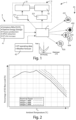
- Fig. 1 it is illustrated schematically a managing and controlling hybrid gas turbine system, wholly indicated by the reference number 1, that includes, in general, a control logic unit 2, a hybrid gas turbine 3, comprising, in its turn, a gas turbine 31, and an electric motor/generator 32, both operatively connected to the control logic unit 2 through a fuel controller module 311, and an electric motor/generator controller 321, respectively.
- the control logic unit 2 is configured to control the operation of the hybrid gas turbine 3, as better explained below, fulfilling constraints and optimizing the use of the resources, namely the fuel of the gas turbine 31 and the power absorbed or supplied by the electric motor/generator 32.
- control logic unit 2 can be realized in different ways.
- the control logic unit 2 is fully embodied in a circuit board, directly installed in the managing and controlling hybrid gas turbine system, with previously installed processing components, such as a microprocessor, a PLC, and the like, which are properly programmed, so as to carry out the management and control operation.
- the control logic unit 2 can be at least in part realized as a software, remotely run with respect to the managing and controlling hybrid gas turbine system.
- the control logic unit 2 can be a common personal computer or a terminal in general, which is programmed to interface with the hybrid gas turbine system, receiving instruction from another, possibly remote with respect to it.
- control logic unit 2 is configured to receive data from several sources 4, and therefore as much types of variables and data, used as input of the monitoring and controlling method, based on an optimization algorithm. This is aimed at allowing the gas turbine 31 to run always preferably at 100%, thus maximizing the capex, adding revenues stream and reducing CO 2 and No x emission in complete automatic mode based on process condition and financial inputs.
- the managing and controlling hybrid gas turbine system 1 also operates in predictive mode, i.e. whether forecast for renewable availability and energy storage using pipeline as vessel, trading of electric energy or fuel. The control will act in dynamic mode, so that the maximization is kept always at the best possible level.
- a first group of data or variables 41 comprises operator's target rankings, that in general includes constraints regarding the emission of CO, CO 2 , and NO x , the pipeline energy storage, which comprises the capability of a pipeline to store energy for example in a pipeline management, and process production, operating expenditures, and requirements to increase the life of the gas turbine 31. These data are usually received from the operator.
- a second group of data or variables 42 can comprise gas turbine operating data and weather forecasts. It is known, in fact, that the weather affect considerably the operation of a gas turbine.
- Fig. 2 shows the percentage of operation of ISO base load of the gas turbine 31, as a function of the ambient temperature.
- T th the power generated by the gas turbine 31 decreases remarkably with the increasing ambient temperature T .
- the electric motor/generator 32 operates as helper or not.
- the operation of the electric motor/generator 32 as helper has the only effect to shift the threshold temperature T th toward a higher temperature (namely on the right of the abscissa of the graph).
- a third group of data 43 can come from one or more energy sources or power plants the hybrid gas turbine system 3 is connected to, such as, by way of example, a grid energy storage 431, a solar panel power plant 432, a wind power plant 433, a hydrothermal power plant 434, and a thermal power plant 435.
- a grid energy storage 431 a solar panel power plant 432, a wind power plant 433, a hydrothermal power plant 434, and a thermal power plant 435.
- the gas turbine 31 can be of different types, such as, by way of example and not limitation: a heavy duty, gas turbine, or aeroderivative gas turbine. In a case where different types of gas turbines 31 are installed, the related control variables or parameters may change. However, the installation of different gas turbines 31 or the other possible hybrid architecture, as better specified below, would not change the scope of protection of the solution herein disclosed.
- the electric motor/generator 32 can be also of different type.
- a type of electric motor/generator 32 is the variable frequency drive electric motor (VFD electric motor) 32, which is very often used in the field in combination with gas turbines 31 for several functions, and in particular as a generator or motor, as better explained in the following.
- VFD electric motor variable frequency drive electric motor
- the use of this type of electric motor/generator 32 is often motivated by the fact that it is particularly useful for electrical control.
- the control logic unit 2 may include: a processor 21, a bus 22, to which the processor 21 is connected to, a database 23, connected to the bus 22, so as to be accessed and controlled by the processor 21, a computer-readable memory 24, also connected to the bus 22, so as to be accessed and controlled by the processor 21, a receiving-transmitting module 25, connected to the bus 22, configured to transmit control signals to the fuel controller module 311 of the gas turbine 31, and to the an electric motor/generator controller 321 of the electric motor/generator 32, to control the operations of the hybrid gas turbine system 3, in the different operation modes available.
- the monitoring and controlling method herein described controls the gas turbine 31 and the electric motor/generator 32 for optimizing the operation of the hybrid gas turbine system 3.
- the processor 21 running one or more computer programs sent to the fuel controller module 311, and to the electric motor/generator controller 321 the optimization of the hybrid gas turbine system 3 is achieved.
- the fuel controller module 311 and the electric motor/generator controller 321 respectively control the actuators of the gas turbine 31, and the electric motor/generator 32, to select the operating patterns for their operation.
- the control logic unit is installed close to the train system.
- the control logic unit 2 is configured to execute one or more computer programs for carrying out an optimization method or algorithm aimed at controlling the hybrid gas turbine system 3.
- the control logic unit 2 can be a physical hardware, possibly installed close to the hybrid gas turbine 3 installation, or remotely arranged.
- the control logic unit 2 can also be based or run in a cloud.
- control logic unit 2 that transmits the control signal is required to be installed close to the train system, while a data processing part can be located remote with respect to the train system, and, as mentioned, in a cloud-based system or near or at the location where the control room (or computer / server / terminals) is located, wherein the control room / computer / server is coupled via wire or wireless means to the train system or the control signal transmission part.
- the controlling and managing method based on an optimization algorithm, one embodiment of which is better explained below, has, as input, the data and variables coming from the sources 4, namely the first 41, the second 42, and the third 43 groups of data and variables. These groups of data 41, 42, and 43 are then organized, for example, in three sets or vectors, in order to be processed.
- the controlling and managing method can process all the data and the variables or a part of them, so that the method can be flexible.
- the same algorithm based on which the controlling and managing method is based, can be used for optimizing a subset of data or for adapting to different layouts of hybrid gas turbine systems. This is done, as better explained below, by setting at zero or at one (or, in general, at a value difference from zero) a set of weighting parameters, used for selecting or not one or more parameters or variables.
- the monitoring and controlling optimization method/algorithm is based on a set of equations for a multivariate regression analysis in a multi-objective optimization problem.
- control functions f k (x, u, w) represent relation between the different variables of the model, as better explained below.
- the variable vector x comprises state variables and can contain both measured values (instruments) and calculated values (through tables and/or known functions) or estimated values (through estimators). Such state variable vector x describe the operating state of the gas turbine 31 and of the electric motor/generator 32. In the following, an example of the state variables x organized as a vector is provided, taking in consideration that different variables or additional variables can be considered
- Another vector u comprises control variables, which are the outputs of the control logic unit 2 for driving the fuel controller module 311, and the electric motor/generator controller 321.
- An example of control variable u, arranged as a column vector, is reported below u fuel demand inlet guide vanes demand variable stator vanes demand variable bleed vanes demand bleed valve demand over ⁇ board bleed vanes demand axial antisurge valve demand nozzle guide vanes centrifugal antisurge valve demand compressor inlet vanes demand motor setpoint reactive power setpoint ⁇
- the third variable vector w comprises external variables or data or parameters, which can include also economic parameters and constraints such as the fuel cost or the taxes to be charged for operating the system.
- the control data or variables w includes actually data and constraints normally set either by the operator or by an external agent.
- the variables processed by the method for monitoring and controlling a hybrid gas turbine system is designed to process three sets of variables, namely the above-mentioned state variables x, control variables u, and external variables w . It is clear that all the variables capable of characterizing the operation of the hybrid gas turbine 3 or, in general, the train system wherein the hybrid gas turbine system 3 is provided, can include additional variables or grouping thereof.
- the method for controlling a hybrid gas turbine system 3 operates a set of optimization variables y i to be optimized. These optimization or target variables y i can be different of the state variables x, control variables u, and external variables w , or even a subset thereof.
- the optimization variables y i can also be organized in column vector.
- the optimization method minimizes the equation above through the application also of a weight vector ⁇ i for each summed factor ⁇ y i - f i ( x, u, w ) ⁇ .
- the optimization variables y i have in common the same measure, namely they should be in principle measured by the same metrics.
- the optimization variables y i can be the capex costs of the plant, so that they should be measured in US$.
- the optimization variables y i can be the power consumption of the plant, in which case the variables should be measured in MW.
- each of the parameters y i would represent the cost of the operation of the plant, such as the fuel cost, the maintenance, the cost of the fines in case of excess of emissions, and so on.
- a possible optimization variable y i of a set can be the torque/speed ratio of the electric motor/generator 32, which is a known parameters of any electrical machine.
- each of the control functions f i ( x, u, w) expresses the relation between each of the parameters y i and the state variables x, the control variables u, and the external parameters w .
- the cost of the fuel e.g. expressed in US$, would be function of the type of operation selected (use of the electric motor/generator 32 as starter/helper mode, generator mode, etc.), the power generated by the electric motor/generator 32, the current cost of the fuel and the fuel consumption by the gas turbine 31 as a function of the environmental temperature and humidity.
- the cost of the fuel although expressed in terms of a currency, namely US$, likewise, preferably, all the other parameters of the optimization variables y i , is a function of several other parameters and variables, both technical (necessarily), and non-technical.
- the model at the end of the optimization process, find the most appropriate set of values for the control variables u , which include usually technical variables, to drive, at the end of the process, the fuel controller module 311, and the electric motor/generator controller 321, obtaining the required optimized adjustment.
- control functions f i ( x, u, w ) are usually non-linear functions and can vary, for example, from gas turbine and gas turbine, as well as from electric motor/generator and electric motor/generator.
- the cost of the fuel employed is a function of the power generated by the gas turbine 31 of the hybrid gas turbine 3, which is a specific function of the machine.
- the weight parameters ⁇ i are applied to set relative weights among the different optimization variables y i .
- the algorithm underlying the monitoring and controlling method can be flexible.
- the corresponding optimization variable y i would be excluded by the optimization process.
- This also allows to simplify the algorithm, adapting the same to a subset of variables received or available, or even to adapt the same algorithm, and therefore the monitoring and controlling method, to a different hybrid gas turbine system 3, may be having a different layout.
- subsets of the weight parameters ⁇ i is preset or selected, in order to drive the optimization method 5 for monitoring and controlling a hybrid gas turbine system according to specific patterns, to achieve certain results, such as maximize the power to be generated, maximize the life of the gas turbine 31, minimize the emissions, and so on.
- the logic control unit 2 can send one or more command signals to the fuel controller module 311, and to the electric motor/generator controller 321, so as to control their operation and select the hybrid gas turbine system 3, tuning, in particular, the fuel consumption of the gas turbine 31, and the power generated by the electric motor/generator 32, while operating as a motor, and therefore the power supplied by the electric motor/generator 32 helps the gas turbine 31, or as a generator, and therefore the power generated is injected for example in the electric grid (not shown in the figures).
- the operation of the controlling and monitoring method, as well as of the gas turbine system 1 is as follows.
- the control logic unit 2 receives the data from the several sources 4, which it is connected to, the data (or variables) are organized in subsets. In particular, for ease of description, they are organized according to tree sets or vectors above-mentioned, namely the state variables x, the control variables u, and the external variables w, which are then processed by the processor 21. It is clear that the division of the variables according to the above three sets or vector is only formal, and a different grouping can be arranged (or no grouping at all).
- the processor 21, retrieves in the embodiment disclosed in Fig. 4 , the computer program to be processed memorized in the computer-readable memory 24, to process the data received. Subsequently, the data are processed on the basis of an optimization algorithm, of which an embodiment has been disclosed above, so as to find an optimization of the control the gas turbine 31, and the electric motor/generator 32.
- Fig. 5 illustrates an embodiment of hybrid gas turbine 3, comprising a variable frequency drive electric motor (VFD electric motor) 32, as electric motor/generator, and a gas turbine 31, connected downstream the VFD electric motor 32.
- VFD electric motor variable frequency drive electric motor
- the load L is connected to the gas turbine 31.
- the VFD electric motor 32 is capable of generating an electric power of 1-3MW. It is intended that the VFD electric motor 32 can be of different type, and capable of generating different power.
- the VFD electric motor 32 is usually implemented in the field since it turns out to be particularly easy to manage and control electrically.
- the gas turbine 31 is designed to generate a power supply of 30MW. Also in this case, the gas turbine 31 is exemplary and different type of gas turbines 31 can be provided.
- Figs. 6 and 7 two different operation modes of a hybrid gas turbine 2 are shown. More specifically, in Fig. 6 the VFD electric motor 32 is operated as starter/helper mode, where the VFD electric motor 32 supplies (maximum) 2MW the gas turbine 31, so as to supply the load L with a total amount of (maximum) 32MW of power.
- the gas turbine 31 is operated in the starter/generator mode, so that the gas turbine 31 supplies the load L with (maximum) 28MW and the VFD electric motor 32 with (maximum) 2MW.
- the VFD electric motor 32 can be also connected to the power grid (not shown in the figures) so as to inject power into the same.
- the operation of the hybrid gas turbine system 3 can be operated by the logic control unit 2, selecting the different operating modes, optimizing the operation with respect to the circumstances, namely depending on any layout of hybrid gas turbine 3.
- processor 21 (or processing means in general) processes the various vectors and variables of each, depends, in part, on the requirement of the load L and the constraints received to maximize some of the optimization variables y i , so as to maximize either operating performance of the hybrid gas turbine system 3 or the cost of the power to be supplied.
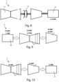
- FIG. 8 another layout of a train system is shown, where the load L is connected to a 30MW gas turbine 31 through a disconnecting device 33, and a 30MW VFD electric motor 32 is connected to the load L as well.
- disconnecting devices 33 installed in the train systems are clutches, of self-synchronizing clutch or over running types.
- Such clutches are equipped with devices known as lock-in and lock-out devices, which, when activated, have the function of locking the clutch in an engaged or disengaged position.
- Fig. 9 illustrates the operation of the hybrid gas turbine 3 in helper mode, when both the gas turbine 31 as well as the VFD electric motor 32 generate the maximum power to the load L, which in this case is (maximum) 60MW (namely, the sum of the maximum power, for example, generated by the gas turbine 31 and the VFD electric motor 32; or in full electric mode, where the gas turbine 31 is shut down and the VFD electric motor 32 supplies the load L, with a (maximum) power of 30MW.
- the disconnecting device 33 is disconnected.
- Fig. 10 depicts the hybrid gas turbine system 3 operating in generator mode, where the gas turbine 31 is able to generate, for instance, (maximum) 30MW power, part of which (for example 50% of the maximum power generated by the gas turbine 31, namely 15MW) is absorbed by the load L, and the residual 50% of the power generated, always 15MW is absorbed by the VFD electric motor 32, and thus injected in the power grid (not shown) the VFD electric motor 32 is connected to.
- the gas turbine 31 is able to generate, for instance, (maximum) 30MW power, part of which (for example 50% of the maximum power generated by the gas turbine 31, namely 15MW) is absorbed by the load L, and the residual 50% of the power generated, always 15MW is absorbed by the VFD electric motor 32, and thus injected in the power grid (not shown) the VFD electric motor 32 is connected to.
- the appropriate adjustment of the power to be generated by the gas turbine 31 or absorbed by the VFD electric motor 32 and/or to be absorbed by the load L (a pump, a compressor or the like) and the VFD electric motor 32, in the different operating mode, is a matter or proper optimization, depending on the several variables or groups of data 41, 42, and 43 briefly listed above.
- the monitoring and controlling method is flexible, as it can adapt to different layouts.
- the state variable "clutch feedback” will be not used in the hybrid gas turbine system 3 shown in Fig. 5 , while it is used in in the layout of the hybrid gas turbine system 3 of Fig. 8 or the layout provided with two clutches. Therefore, by the right selection of the control functions f i ( x, u, w), by way of setting of the appropriate values of the weight parameters ⁇ i , it possible to realize any possible layout of hybrid gas turbine system 3.
- FIG. 5 In addition to the layouts shown in Figs. 5, 6, 7 , 8, 9 and10, other layouts can be foreseen. More specifically, other embodiments can include a hybrid gas turbine system 3 similar to that shown in Fig. 8 , where an additional clutch is interposed between the load L and the electric motor/generator 32.
- a possible layout would provide a gas turbine, an electric motor/generator 32, between which a first clutch is interposed, a load, and a second clutch, interposed between the a electric motor/generator 32 and the load L.
- the monitoring and controlling method 5 herein disclosed can be also appreciated looking at the flowchart of Fig. 11 , showing the following steps:
- the electric motor/generator 32 can be connected to a grid energy storage 431, to a solar panel power plant 432, to a wind power plant 433, to a hydrothermal power plant 434, or to a thermal power plant 435, or to any general power grid, into which it is capable of injecting any excess energy.
- a grid energy storage 431, a solar panel power plant 432, a wind power plant 433, a hydrothermal power plant 434, or a thermal power plant 435 can be operatively connected the control logic unit 2, from which the latter can gather data, such as part of the external variables w.
- Fig. 12 it is in particular illustrated how the control logic unit 2, and in particular the a receiving-transmitting module 25, transmits (step 57) the control signals received by the processor 21 to the fuel controller module 311 of the gas turbine 31, and transmits (step 58) the an electric motor/generator controller 321 of the electric motor/generator 32.
Landscapes
- Engineering & Computer Science (AREA)
- Chemical & Material Sciences (AREA)
- Combustion & Propulsion (AREA)
- Mechanical Engineering (AREA)
- General Engineering & Computer Science (AREA)
- Control Of Eletrric Generators (AREA)
Claims (19)
- Verfahren (5) zum Überwachen und Steuern eines Hybridgasturbinensystems (3), wobei das Hybridgasturbinensystem (3) mindestens eine Gasturbine (31), die durch Kraftstoff betrieben werden soll, mindestens einen Elektromotor/Generator (32), der in der Lage ist, als ein Generator oder als ein Motor betrieben zu werden, und eine Vielzahl von Aktuatoren für deren Steuerung umfasst, und wobei das Verfahren (5) durch eine Steuerlogikeinheit (2) implementiert wird, dadurch gekennzeichnet, dass das Verfahren (5) die folgenden Schritte einschließt:Empfangen (51) eines Satzes von Betriebsvariablen x zum Erfassen der Betriebszustände der Gasturbine (31) und des Elektromotors/Generators (32);Empfangen (53) eines Satzes von externen Variablen w;Auswählen (52) eines Satzes von Steuervariablen u zum Steuern der Betriebszustände der Gasturbine (31) und des Elektromotors/Generators (32);Einstellen (54) eines Satzes von Optimierungsvariablen y,wobei die Werte der Optimierungsvariablen y von den Betriebsvariablen x, den Steuervariablen u und den externen Variablen w abhängen, undwobei die Werte der Optimierungsvariablen y zum Optimieren angepasst werden müssen;Verarbeiten (55) einer oder mehrerer der Betriebsvariablen x, der Steuervariablen u und der externen Variablen w durch Optimieren der Werte der Optimierungsvariablen y; undErzeugen und Übertragen (56) eines oder mehrerer Steuersignale basierend auf der Steuervariablen u wie sie durch die Optimierung der Optimierungsvariablen y erreicht werden, um die Aktuatoren des Hybridgasturbinensystems (3) zu steuern;wobei die Optimierungsvariablen yi eine Funktion der Betriebsvariablen x und/oder der Steuervariablen u und/oder der externen Variablen w durch Steuerfunktionen fi (x, u, w) sind, undwobei der Optimierungsschritt (55) ausgeführt wird, wobei die Summe der Module der Optimierungsvariablen yi und der Steuerfunktion fi (x, u, w) gemäß der folgenden Gleichung minimiert wird:


- Verfahren (5) nach Anspruch 1, wobei das eine oder die mehreren Steuersignale die Steuerung des Kraftstoffs, der die Gasturbine (31) versorgt, und der Leistung ermöglichen, die durch den Elektromotor/Generator (32) erzeugt oder umgewandelt wird.
- Verfahren (5) nach einem der vorstehenden Ansprüche, wobei die Optimierungsvariablen yi eine Teilmenge der Betriebsvariablen x und/oder der Steuervariablen u und/oder der externen Variablen w sind.
- Verfahren (5) nach Anspruch 1, umfassend den Schritt eines Auswählens einer Teilmenge der Gewichtungsparameter αi , um die eine oder die mehreren der Betriebsvariablen x, der Steuervariablen u und der externen Variablen w zu verarbeiten, durch Optimieren der Werte der Optimierungsvariablen y gemäß bestimmten Mustern, wie etwa einem Maximieren der Leistung, die erzeugt werden soll, dem Maximieren der Lebensdauer der Gasturbine (31), dem Minimieren der Emissionen und dergleichen.
- Verfahren (5) nach einem der vorstehenden Ansprüche, wobei die Zustandsvariablen x mindestens eine der folgenden Variablen umfassen: Umgebungsdruck, Umgebungsdruck, Umgebungsfeuchtigkeit, Turbineneinlasstemperatur, Turbineneinlassdruck, Turbinenkompressorauslasstemperatur, Turbinenkompressorauslassdruck, Turbinenkompressorluftstrom, Einlassfilterverluste, Kraftstofftemperatur, Kraftstoffzusammensetzung, Verbrennungsmodus, Hochleistungsturbinendrehzahl, Temperatur einer ersten Düse, Hochleistungsturbinenauslasstemperatur, Hochleistungsturbinenauslassdruck, Hochleistungsturbinenstrom, Boost-Turbinendrehzahl, Boost-Turbinenauslasstemperatur, Boost-Turbinenstrom, Niedrigleistungsturbinendrehlzahl, Niedrigleistungsturbinenauslasstemperatur, Niedrigleistungsturbinenstrom, Einlassdruck eines angetriebenen Kompressors, Einlasstemperatur des angetriebenen Kompressors, Einlassstrom des angetriebenen Kompressors, Auslasstemperatur des angetriebenen Kompressors, Auslassdruck des angetriebenen Kompressors, Elektromotorleistung, Emissionen, Lebensdauer, Kupplung, Rückmeldung.
- Verfahren (5) nach einem der vorstehenden Ansprüche, wobei die Steuervariablen u, um die Steuersignale zu erzeugen, mindestens eine der folgenden Variablen umfassen: Kraftstoffbedarf, Bedarf an Einlassleitschaufeln, Bedarf an variablen Statorschaufeln, Bedarf an variablen Entlüftungsschaufeln, Bedarf an Entlüftungsventilen, Bedarf an Entlüftungsschaufeln über Bord, Bedarf an axialen Umluftventilen, Düsenleitschaufeln, Bedarf an Zentrifugalumluftventilen, Bedarf an Kompressoreinlassschaufeln, Motorsollwert, Blindleistungssollwert.
- Verfahren (5) nach einem der vorstehenden Ansprüche, wobei die externen Variablen w mindestens eine der folgenden Variablen umfassen: Kraftstoffkosten, Verkaufspreis elektrischer Energie, Kosten elektrischer Energie, Emissionssteuern, Wartungskosten, zusätzliche Energieverfügbarkeit, Kosten/Preis von Blindleistung, Leistungsfaktor.
- Verfahren (5) nach einem der vorstehenden Ansprüche, wobei die Gasturbine (31) eine leistungsstarke oder eine aeroderivative Gasturbine ist.
- Steuerlogikeinheit (2), umfassend:einen Prozessor (21), der konfiguriert ist, um das Verfahren nach einem der Ansprüche 1 bis 8 durchzuführen; undein Empfangs-/Sendemodul (25), das mit dem Prozessor (21) verbindbar ist und konfiguriert ist, um die Steuersignale zu senden (57), die durch den Prozessor (21) empfangen werden, um die Aktuatoren des Hybridgasturbinensystems (3) zu steuern.
- Steuerlogikeinheit (2) nach Anspruch 9, umfassend:einen Bus (22), mit dem der Prozessor (21) verbunden ist;eine Datenbank (23), die mit dem Bus (22) verbunden ist, so dass sie durch den Prozessor (21) aufgerufen und gesteuert werden kann; undeinen computerlesbaren Speicher (24), der mit dem Bus (22) verbunden ist, so dass er durch den Prozessor (21) aufgerufen und gesteuert werden kann.
- Hybridgasturbinensystem (3), umfassend:mindestens eine Gasturbine (31), die durch Kraftstoff betrieben werden soll, umfassend ein Kraftstoffsteuermodul (311), das zum Steuern des Kraftstoffs betreibbar ist, mit dem die Gasturbine (3) versorgt werden soll; undmindestens einen Elektromotor/Generator (32), der in der Lage ist, als ein Generator oder als ein Motor betrieben zu werden, umfassend eine Elektromotor/Generator-Steuerung (321), die geeignet ist, um die elektrische Leistung zu steuern und einzustellen, die durch den Elektromotor/Generator (32) erzeugt oder umgewandelt wird;dadurch gekennzeichnet, dass das Hybridgasturbinensystem (3) die Steuerlogikeinheit (2) nach einem der Ansprüche 9 oder 10 umfasst, die mit dem Kraftstoffsteuermodul (311) und mit der Elektromotor/Generator-Steuerung (321) wirkverbunden ist.
- Hybridgasturbinensystem (3) nach Anspruch 11, wobei das Empfangs-/Sendemodul (25) der Steuerlogikeinheit (2) konfiguriert ist, um die Steuersignale, die durch den Prozessor (21) empfangen werden, an das Kraftstoffsteuermodul (311) der Gasturbine (31) zu senden (57) und um die Steuersignale an die Elektromotor/Generator-Steuerung (321) des Elektromotors/Generators (32) zu senden (58).
- Stromerzeugungsanlage, umfassend das Hybridgasturbinensystem (3) nach einem der Ansprüche 11 oder 12, wobei der elektrische Motor/Generator (32) mit mindestens einer Stromerzeugungsanlage (41, 42, 43, 44, 45) verbunden ist.
- Stromerzeugungsanlage nach Anspruch 13, wobei die mindestens eine Stromerzeugungsanlage einen Netzenergiespeicher (431), eine Solarpanelstromerzeugungsanlage (432), eine Windstromerzeugungsanlage (433), eine hydrothermale Stromerzeugungsanlage (434) und/oder eine thermische Stromerzeugungsanlage (435) umfasst.
- Last, umfassend das Hybridgasturbinensystem (3) nach Anspruch 11 oder 12, wobei die Gasturbine (31) mit der Last (L), beispielsweise einer Pumpe oder einem Kompressor, verbunden ist.
- Last nach Anspruch 15, wobei die Gasturbine (31) mit der Last (L) über eine Trennvorrichtung (33) wie etwa eine selbstsynchronisierende Kupplung oder einen Freilauf verbunden ist.
- Last nach Anspruch 16, wobei die Trennung oder Verbindung, die durch die Trennvorrichtung hergestellt wird, durch einen Betreiber manuell und/oder durch einen Aktuator automatisch betrieben wird.
- Hybridgasturbinensystem (3), die Stromerzeugungsanlage oder die Last nach einem der Ansprüche 11 bis 17, wobei der Elektromotor/Generator (32) ein Elektromotor mit variablem Frequenzantrieb (VFD-Elektromotor) ist.
- Hybridgasturbinensystem (3), die Stromerzeugungsanlage oder die Last nach einem der Ansprüche 11 bis 18, wobei die Gasturbine (2) eine leistungsstarke oder aeroderivative Gasturbine ist.
Applications Claiming Priority (2)
| Application Number | Priority Date | Filing Date | Title |
|---|---|---|---|
| IT102020000016009A IT202000016009A1 (it) | 2020-07-02 | 2020-07-02 | Metodo per monitorare e controllare un sistema di turbina a gas ibrida e relativo sistema |
| PCT/EP2021/025231 WO2022002436A1 (en) | 2020-07-02 | 2021-06-24 | Method for monitoring and controlling a hybrid gas turbine system and system thereof |
Publications (2)
| Publication Number | Publication Date |
|---|---|
| EP4176167A1 EP4176167A1 (de) | 2023-05-10 |
| EP4176167B1 true EP4176167B1 (de) | 2025-04-30 |
Family
ID=72356430
Family Applications (1)
| Application Number | Title | Priority Date | Filing Date |
|---|---|---|---|
| EP21736245.8A Active EP4176167B1 (de) | 2020-07-02 | 2021-06-24 | Verfahren zur überwachung und steuerung eines hybriden gasturbinensystems und system dafür |
Country Status (10)
| Country | Link |
|---|---|
| US (1) | US12123346B2 (de) |
| EP (1) | EP4176167B1 (de) |
| JP (1) | JP7670361B2 (de) |
| KR (1) | KR102918859B1 (de) |
| CN (1) | CN115812121B (de) |
| AU (1) | AU2021300507B2 (de) |
| CA (1) | CA3184171A1 (de) |
| GB (1) | GB2612219B (de) |
| IT (1) | IT202000016009A1 (de) |
| WO (1) | WO2022002436A1 (de) |
Families Citing this family (2)
| Publication number | Priority date | Publication date | Assignee | Title |
|---|---|---|---|---|
| IT202200008633A1 (it) * | 2022-04-29 | 2023-10-29 | Nuovo Pignone Tecnologie Srl | Stazione di compressione a basse emissioni senza isola di generazione di energia dedicata |
| IT202200008660A1 (it) * | 2022-04-29 | 2023-10-29 | Nuovo Pignone Tecnologie Srl | Stazione di compressione a basse emissioni di carbonio con capacità d’uso duale |
Family Cites Families (11)
| Publication number | Priority date | Publication date | Assignee | Title |
|---|---|---|---|---|
| US6912451B2 (en) * | 2001-09-06 | 2005-06-28 | Energy Transfer Group, Llc | Control system for a redundant prime mover system |
| JP3930371B2 (ja) * | 2002-04-24 | 2007-06-13 | 三菱重工業株式会社 | ガスタービン制御装置、ガスタービンシステム及びガスタービン制御方法 |
| WO2009109446A1 (de) * | 2008-03-05 | 2009-09-11 | Alstom Technology Ltd | Verfahren zur regelung einer gasturbine in einem kraftwerk und kraftwerk zur durchführung des verfahrens |
| JP4995169B2 (ja) * | 2008-09-29 | 2012-08-08 | 三菱重工業株式会社 | ガスタービン制御方法及び装置 |
| JP2011048688A (ja) * | 2009-08-27 | 2011-03-10 | Hitachi Ltd | プラントライフサイクル評価装置及び方法 |
| ITFI20120292A1 (it) * | 2012-12-24 | 2014-06-25 | Nuovo Pignone Srl | "gas turbines in mechanical drive applications and operating methods" |
| ITFI20130130A1 (it) * | 2013-05-31 | 2014-12-01 | Nuovo Pignone Srl | "gas turbines in mechanical drive applications and operating methods" |
| US9494086B2 (en) * | 2014-02-28 | 2016-11-15 | General Electric Company | Systems and methods for improved combined cycle control |
| US10094297B2 (en) * | 2014-09-09 | 2018-10-09 | Hitachi, Ltd. | Power generation system and power generation method |
| US20160147204A1 (en) * | 2014-11-26 | 2016-05-26 | General Electric Company | Methods and systems for enhancing control of power plant generating units |
| US9926852B2 (en) * | 2015-03-03 | 2018-03-27 | General Electric Company | Methods and systems for enhancing control of power plant generating units |
-
2020
- 2020-07-02 IT IT102020000016009A patent/IT202000016009A1/it unknown
-
2021
- 2021-06-24 GB GB2300309.8A patent/GB2612219B/en active Active
- 2021-06-24 WO PCT/EP2021/025231 patent/WO2022002436A1/en not_active Ceased
- 2021-06-24 JP JP2022578679A patent/JP7670361B2/ja active Active
- 2021-06-24 CA CA3184171A patent/CA3184171A1/en active Pending
- 2021-06-24 AU AU2021300507A patent/AU2021300507B2/en active Active
- 2021-06-24 CN CN202180047386.XA patent/CN115812121B/zh active Active
- 2021-06-24 EP EP21736245.8A patent/EP4176167B1/de active Active
- 2021-06-24 KR KR1020237003144A patent/KR102918859B1/ko active Active
- 2021-06-24 US US18/003,631 patent/US12123346B2/en active Active
Also Published As
| Publication number | Publication date |
|---|---|
| AU2021300507B2 (en) | 2024-05-02 |
| WO2022002436A1 (en) | 2022-01-06 |
| EP4176167A1 (de) | 2023-05-10 |
| CA3184171A1 (en) | 2022-01-06 |
| KR20230028533A (ko) | 2023-02-28 |
| JP2023531454A (ja) | 2023-07-24 |
| GB2612219A (en) | 2023-04-26 |
| US20230243302A1 (en) | 2023-08-03 |
| JP7670361B2 (ja) | 2025-04-30 |
| AU2021300507A1 (en) | 2023-02-23 |
| KR102918859B1 (ko) | 2026-01-27 |
| IT202000016009A1 (it) | 2022-01-02 |
| CN115812121B (zh) | 2025-06-13 |
| BR112023000009A2 (pt) | 2023-01-31 |
| GB2612219B (en) | 2024-07-10 |
| US12123346B2 (en) | 2024-10-22 |
| CN115812121A (zh) | 2023-03-17 |
Similar Documents
| Publication | Publication Date | Title |
|---|---|---|
| RU2381386C2 (ru) | Способ оптимизации эксплуатации множества компрессорных агрегатов и устройство для этого | |
| US9853581B2 (en) | Lifing and performance optimization limit management for turbine engine | |
| US8727736B2 (en) | Multiple electric motors driving a single compressor string | |
| EP4176167B1 (de) | Verfahren zur überwachung und steuerung eines hybriden gasturbinensystems und system dafür | |
| US8676554B2 (en) | Simulation apparatus for motor-driven compressor system and the simulation method thereof | |
| AU2022386378B2 (en) | Power plant for controlling the renewable energy use in an lng train | |
| US20250286376A1 (en) | Power plant having a flexible firm skid | |
| EP4430287B1 (de) | Verfahren zur steuerung der nutzung erneuerbarer energien in einer lng-prozesslinie | |
| BR112023000009B1 (pt) | Método e sistema para monitorar e controlar um sistema de turbina a gás híbrida, e unidade lógica de controle | |
| US12573855B2 (en) | Power plant having a flexible firm skid | |
| EP4528962A1 (de) | Kraftwerk mit flexiblem festgleit | |
| Turetskov et al. | Increasing the Economic Operation of Steam Turbines by Optimizing the Operating Modes of the Control Stage | |
| Takeda et al. | Advanced Control Technique Of Centrifugal Compressor For Complex Gas Compression Processes. | |
| Federico et al. | Performance/Cost Assessment of a Variable Frequency Drive (VFD) Control Applied to a Brazilian Long Pipeline |
Legal Events
| Date | Code | Title | Description |
|---|---|---|---|
| STAA | Information on the status of an ep patent application or granted ep patent |
Free format text: STATUS: UNKNOWN |
|
| STAA | Information on the status of an ep patent application or granted ep patent |
Free format text: STATUS: THE INTERNATIONAL PUBLICATION HAS BEEN MADE |
|
| PUAI | Public reference made under article 153(3) epc to a published international application that has entered the european phase |
Free format text: ORIGINAL CODE: 0009012 |
|
| STAA | Information on the status of an ep patent application or granted ep patent |
Free format text: STATUS: REQUEST FOR EXAMINATION WAS MADE |
|
| 17P | Request for examination filed |
Effective date: 20230113 |
|
| AK | Designated contracting states |
Kind code of ref document: A1 Designated state(s): AL AT BE BG CH CY CZ DE DK EE ES FI FR GB GR HR HU IE IS IT LI LT LU LV MC MK MT NL NO PL PT RO RS SE SI SK SM TR |
|
| P01 | Opt-out of the competence of the unified patent court (upc) registered |
Effective date: 20230526 |
|
| DAV | Request for validation of the european patent (deleted) | ||
| DAX | Request for extension of the european patent (deleted) | ||
| GRAP | Despatch of communication of intention to grant a patent |
Free format text: ORIGINAL CODE: EPIDOSNIGR1 |
|
| STAA | Information on the status of an ep patent application or granted ep patent |
Free format text: STATUS: GRANT OF PATENT IS INTENDED |
|
| INTG | Intention to grant announced |
Effective date: 20250217 |
|
| GRAS | Grant fee paid |
Free format text: ORIGINAL CODE: EPIDOSNIGR3 |
|
| GRAA | (expected) grant |
Free format text: ORIGINAL CODE: 0009210 |
|
| STAA | Information on the status of an ep patent application or granted ep patent |
Free format text: STATUS: THE PATENT HAS BEEN GRANTED |
|
| AK | Designated contracting states |
Kind code of ref document: B1 Designated state(s): AL AT BE BG CH CY CZ DE DK EE ES FI FR GB GR HR HU IE IS IT LI LT LU LV MC MK MT NL NO PL PT RO RS SE SI SK SM TR |
|
| RAP3 | Party data changed (applicant data changed or rights of an application transferred) |
Owner name: NUOVO PIGNONE TECNOLOGIE - S.R.L. |
|
| REG | Reference to a national code |
Ref country code: CH Ref legal event code: EP Ref country code: GB Ref legal event code: FG4D |
|
| REG | Reference to a national code |
Ref country code: DE Ref legal event code: R096 Ref document number: 602021030020 Country of ref document: DE |
|
| REG | Reference to a national code |
Ref country code: IE Ref legal event code: FG4D |
|
| REG | Reference to a national code |
Ref country code: SE Ref legal event code: TRGR |
|
| PGFP | Annual fee paid to national office [announced via postgrant information from national office to epo] |
Ref country code: DE Payment date: 20250520 Year of fee payment: 5 |
|
| PGFP | Annual fee paid to national office [announced via postgrant information from national office to epo] |
Ref country code: GB Payment date: 20250520 Year of fee payment: 5 |
|
| PGFP | Annual fee paid to national office [announced via postgrant information from national office to epo] |
Ref country code: NO Payment date: 20250522 Year of fee payment: 5 |
|
| PGFP | Annual fee paid to national office [announced via postgrant information from national office to epo] |
Ref country code: AT Payment date: 20250721 Year of fee payment: 5 |
|
| PGFP | Annual fee paid to national office [announced via postgrant information from national office to epo] |
Ref country code: SE Payment date: 20250520 Year of fee payment: 5 |
|
| REG | Reference to a national code |
Ref country code: NL Ref legal event code: MP Effective date: 20250430 |
|
| REG | Reference to a national code |
Ref country code: AT Ref legal event code: MK05 Ref document number: 1790213 Country of ref document: AT Kind code of ref document: T Effective date: 20250430 |
|
| PG25 | Lapsed in a contracting state [announced via postgrant information from national office to epo] |
Ref country code: FI Free format text: LAPSE BECAUSE OF FAILURE TO SUBMIT A TRANSLATION OF THE DESCRIPTION OR TO PAY THE FEE WITHIN THE PRESCRIBED TIME-LIMIT Effective date: 20250430 Ref country code: PT Free format text: LAPSE BECAUSE OF FAILURE TO SUBMIT A TRANSLATION OF THE DESCRIPTION OR TO PAY THE FEE WITHIN THE PRESCRIBED TIME-LIMIT Effective date: 20250901 Ref country code: ES Free format text: LAPSE BECAUSE OF FAILURE TO SUBMIT A TRANSLATION OF THE DESCRIPTION OR TO PAY THE FEE WITHIN THE PRESCRIBED TIME-LIMIT Effective date: 20250430 |
|
| REG | Reference to a national code |
Ref country code: LT Ref legal event code: MG9D |
|
| PG25 | Lapsed in a contracting state [announced via postgrant information from national office to epo] |
Ref country code: GR Free format text: LAPSE BECAUSE OF FAILURE TO SUBMIT A TRANSLATION OF THE DESCRIPTION OR TO PAY THE FEE WITHIN THE PRESCRIBED TIME-LIMIT Effective date: 20250731 |
|
| PG25 | Lapsed in a contracting state [announced via postgrant information from national office to epo] |
Ref country code: NL Free format text: LAPSE BECAUSE OF FAILURE TO SUBMIT A TRANSLATION OF THE DESCRIPTION OR TO PAY THE FEE WITHIN THE PRESCRIBED TIME-LIMIT Effective date: 20250430 Ref country code: PL Free format text: LAPSE BECAUSE OF FAILURE TO SUBMIT A TRANSLATION OF THE DESCRIPTION OR TO PAY THE FEE WITHIN THE PRESCRIBED TIME-LIMIT Effective date: 20250430 |
|
| PG25 | Lapsed in a contracting state [announced via postgrant information from national office to epo] |
Ref country code: BG Free format text: LAPSE BECAUSE OF FAILURE TO SUBMIT A TRANSLATION OF THE DESCRIPTION OR TO PAY THE FEE WITHIN THE PRESCRIBED TIME-LIMIT Effective date: 20250430 |
|
| PG25 | Lapsed in a contracting state [announced via postgrant information from national office to epo] |
Ref country code: HR Free format text: LAPSE BECAUSE OF FAILURE TO SUBMIT A TRANSLATION OF THE DESCRIPTION OR TO PAY THE FEE WITHIN THE PRESCRIBED TIME-LIMIT Effective date: 20250430 |
|
| PG25 | Lapsed in a contracting state [announced via postgrant information from national office to epo] |
Ref country code: AT Free format text: LAPSE BECAUSE OF FAILURE TO SUBMIT A TRANSLATION OF THE DESCRIPTION OR TO PAY THE FEE WITHIN THE PRESCRIBED TIME-LIMIT Effective date: 20250430 |
|
| PGFP | Annual fee paid to national office [announced via postgrant information from national office to epo] |
Ref country code: CH Payment date: 20250701 Year of fee payment: 5 |
|
| PG25 | Lapsed in a contracting state [announced via postgrant information from national office to epo] |
Ref country code: RS Free format text: LAPSE BECAUSE OF FAILURE TO SUBMIT A TRANSLATION OF THE DESCRIPTION OR TO PAY THE FEE WITHIN THE PRESCRIBED TIME-LIMIT Effective date: 20250731 |
|
| PG25 | Lapsed in a contracting state [announced via postgrant information from national office to epo] |
Ref country code: IS Free format text: LAPSE BECAUSE OF FAILURE TO SUBMIT A TRANSLATION OF THE DESCRIPTION OR TO PAY THE FEE WITHIN THE PRESCRIBED TIME-LIMIT Effective date: 20250830 |
|
| PG25 | Lapsed in a contracting state [announced via postgrant information from national office to epo] |
Ref country code: LV Free format text: LAPSE BECAUSE OF FAILURE TO SUBMIT A TRANSLATION OF THE DESCRIPTION OR TO PAY THE FEE WITHIN THE PRESCRIBED TIME-LIMIT Effective date: 20250430 |
|
| PG25 | Lapsed in a contracting state [announced via postgrant information from national office to epo] |
Ref country code: DK Free format text: LAPSE BECAUSE OF FAILURE TO SUBMIT A TRANSLATION OF THE DESCRIPTION OR TO PAY THE FEE WITHIN THE PRESCRIBED TIME-LIMIT Effective date: 20250430 Ref country code: SM Free format text: LAPSE BECAUSE OF FAILURE TO SUBMIT A TRANSLATION OF THE DESCRIPTION OR TO PAY THE FEE WITHIN THE PRESCRIBED TIME-LIMIT Effective date: 20250430 |
|
| PG25 | Lapsed in a contracting state [announced via postgrant information from national office to epo] |
Ref country code: CZ Free format text: LAPSE BECAUSE OF FAILURE TO SUBMIT A TRANSLATION OF THE DESCRIPTION OR TO PAY THE FEE WITHIN THE PRESCRIBED TIME-LIMIT Effective date: 20250430 |
|
| PG25 | Lapsed in a contracting state [announced via postgrant information from national office to epo] |
Ref country code: EE Free format text: LAPSE BECAUSE OF FAILURE TO SUBMIT A TRANSLATION OF THE DESCRIPTION OR TO PAY THE FEE WITHIN THE PRESCRIBED TIME-LIMIT Effective date: 20250430 |
|
| PG25 | Lapsed in a contracting state [announced via postgrant information from national office to epo] |
Ref country code: SK Free format text: LAPSE BECAUSE OF FAILURE TO SUBMIT A TRANSLATION OF THE DESCRIPTION OR TO PAY THE FEE WITHIN THE PRESCRIBED TIME-LIMIT Effective date: 20250430 |
|
| PG25 | Lapsed in a contracting state [announced via postgrant information from national office to epo] |
Ref country code: IT Free format text: LAPSE BECAUSE OF FAILURE TO SUBMIT A TRANSLATION OF THE DESCRIPTION OR TO PAY THE FEE WITHIN THE PRESCRIBED TIME-LIMIT Effective date: 20250430 |
|
| PG25 | Lapsed in a contracting state [announced via postgrant information from national office to epo] |
Ref country code: MC Free format text: LAPSE BECAUSE OF FAILURE TO SUBMIT A TRANSLATION OF THE DESCRIPTION OR TO PAY THE FEE WITHIN THE PRESCRIBED TIME-LIMIT Effective date: 20250430 |
|
| REG | Reference to a national code |
Ref country code: DE Ref legal event code: R097 Ref document number: 602021030020 Country of ref document: DE |
|
| PG25 | Lapsed in a contracting state [announced via postgrant information from national office to epo] |
Ref country code: LU Free format text: LAPSE BECAUSE OF NON-PAYMENT OF DUE FEES Effective date: 20250624 |
|
| REG | Reference to a national code |
Ref country code: BE Ref legal event code: MM Effective date: 20250630 |
|
| PG25 | Lapsed in a contracting state [announced via postgrant information from national office to epo] |
Ref country code: RO Free format text: LAPSE BECAUSE OF FAILURE TO SUBMIT A TRANSLATION OF THE DESCRIPTION OR TO PAY THE FEE WITHIN THE PRESCRIBED TIME-LIMIT Effective date: 20250430 |
|
| PLBE | No opposition filed within time limit |
Free format text: ORIGINAL CODE: 0009261 |
|
| STAA | Information on the status of an ep patent application or granted ep patent |
Free format text: STATUS: NO OPPOSITION FILED WITHIN TIME LIMIT |
|
| REG | Reference to a national code |
Ref country code: CH Ref legal event code: L10 Free format text: ST27 STATUS EVENT CODE: U-0-0-L10-L00 (AS PROVIDED BY THE NATIONAL OFFICE) Effective date: 20260311 |
|
| 26N | No opposition filed |
Effective date: 20260202 |
|
| PG25 | Lapsed in a contracting state [announced via postgrant information from national office to epo] |
Ref country code: IE Free format text: LAPSE BECAUSE OF NON-PAYMENT OF DUE FEES Effective date: 20250624 |
|
| PG25 | Lapsed in a contracting state [announced via postgrant information from national office to epo] |
Ref country code: BE Free format text: LAPSE BECAUSE OF NON-PAYMENT OF DUE FEES Effective date: 20250630 |
|
| PG25 | Lapsed in a contracting state [announced via postgrant information from national office to epo] |
Ref country code: FR Free format text: LAPSE BECAUSE OF NON-PAYMENT OF DUE FEES Effective date: 20250630 |