EP4176147B1 - Electronic padlock - Google Patents
Electronic padlock Download PDFInfo
- Publication number
- EP4176147B1 EP4176147B1 EP21739409.7A EP21739409A EP4176147B1 EP 4176147 B1 EP4176147 B1 EP 4176147B1 EP 21739409 A EP21739409 A EP 21739409A EP 4176147 B1 EP4176147 B1 EP 4176147B1
- Authority
- EP
- European Patent Office
- Prior art keywords
- electronic
- spring
- cover part
- shaft
- shaft pin
- Prior art date
- Legal status (The legal status is an assumption and is not a legal conclusion. Google has not performed a legal analysis and makes no representation as to the accuracy of the status listed.)
- Active
Links
Images

Classifications
-
- E—FIXED CONSTRUCTIONS
- E05—LOCKS; KEYS; WINDOW OR DOOR FITTINGS; SAFES
- E05B—LOCKS; ACCESSORIES THEREFOR; HANDCUFFS
- E05B67/00—Padlocks; Details thereof
-
- E—FIXED CONSTRUCTIONS
- E05—LOCKS; KEYS; WINDOW OR DOOR FITTINGS; SAFES
- E05B—LOCKS; ACCESSORIES THEREFOR; HANDCUFFS
- E05B15/00—Other details of locks; Parts for engagement by bolts of fastening devices
- E05B15/004—Lost motion connections
-
- E—FIXED CONSTRUCTIONS
- E05—LOCKS; KEYS; WINDOW OR DOOR FITTINGS; SAFES
- E05B—LOCKS; ACCESSORIES THEREFOR; HANDCUFFS
- E05B15/00—Other details of locks; Parts for engagement by bolts of fastening devices
- E05B15/04—Spring arrangements in locks
-
- E—FIXED CONSTRUCTIONS
- E05—LOCKS; KEYS; WINDOW OR DOOR FITTINGS; SAFES
- E05B—LOCKS; ACCESSORIES THEREFOR; HANDCUFFS
- E05B17/00—Accessories in connection with locks
- E05B17/0054—Fraction or shear lines; Slip-clutches, resilient parts or the like for preventing damage when forced or slammed
- E05B17/0058—Fraction or shear lines; Slip-clutches, resilient parts or the like for preventing damage when forced or slammed with non-destructive disengagement
-
- E—FIXED CONSTRUCTIONS
- E05—LOCKS; KEYS; WINDOW OR DOOR FITTINGS; SAFES
- E05B—LOCKS; ACCESSORIES THEREFOR; HANDCUFFS
- E05B47/00—Operating or controlling locks or other fastening devices by electric or magnetic means
- E05B47/0001—Operating or controlling locks or other fastening devices by electric or magnetic means with electric actuators; Constructional features thereof
- E05B47/0002—Operating or controlling locks or other fastening devices by electric or magnetic means with electric actuators; Constructional features thereof with electromagnets
-
- E—FIXED CONSTRUCTIONS
- E05—LOCKS; KEYS; WINDOW OR DOOR FITTINGS; SAFES
- E05B—LOCKS; ACCESSORIES THEREFOR; HANDCUFFS
- E05B47/00—Operating or controlling locks or other fastening devices by electric or magnetic means
- E05B47/0001—Operating or controlling locks or other fastening devices by electric or magnetic means with electric actuators; Constructional features thereof
- E05B47/0012—Operating or controlling locks or other fastening devices by electric or magnetic means with electric actuators; Constructional features thereof with rotary electromotors
-
- E—FIXED CONSTRUCTIONS
- E05—LOCKS; KEYS; WINDOW OR DOOR FITTINGS; SAFES
- E05B—LOCKS; ACCESSORIES THEREFOR; HANDCUFFS
- E05B49/00—Electric permutation locks; Circuits therefor ; Mechanical aspects of electronic locks; Mechanical keys therefor
-
- E—FIXED CONSTRUCTIONS
- E05—LOCKS; KEYS; WINDOW OR DOOR FITTINGS; SAFES
- E05B—LOCKS; ACCESSORIES THEREFOR; HANDCUFFS
- E05B67/00—Padlocks; Details thereof
- E05B67/06—Shackles; Arrangement of the shackle
- E05B67/22—Padlocks with sliding shackles, with or without rotary or pivotal movement
-
- E—FIXED CONSTRUCTIONS
- E05—LOCKS; KEYS; WINDOW OR DOOR FITTINGS; SAFES
- E05B—LOCKS; ACCESSORIES THEREFOR; HANDCUFFS
- E05B67/00—Padlocks; Details thereof
- E05B67/06—Shackles; Arrangement of the shackle
- E05B67/22—Padlocks with sliding shackles, with or without rotary or pivotal movement
- E05B67/24—Padlocks with sliding shackles, with or without rotary or pivotal movement with built- in cylinder locks
-
- E—FIXED CONSTRUCTIONS
- E05—LOCKS; KEYS; WINDOW OR DOOR FITTINGS; SAFES
- E05B—LOCKS; ACCESSORIES THEREFOR; HANDCUFFS
- E05B15/00—Other details of locks; Parts for engagement by bolts of fastening devices
- E05B15/04—Spring arrangements in locks
- E05B2015/0403—Wound springs
- E05B2015/0406—Wound springs wound in a cylindrical shape
-
- E—FIXED CONSTRUCTIONS
- E05—LOCKS; KEYS; WINDOW OR DOOR FITTINGS; SAFES
- E05B—LOCKS; ACCESSORIES THEREFOR; HANDCUFFS
- E05B15/00—Other details of locks; Parts for engagement by bolts of fastening devices
- E05B15/04—Spring arrangements in locks
- E05B2015/0437—Attachments or mountings; Mounting of springs
-
- E—FIXED CONSTRUCTIONS
- E05—LOCKS; KEYS; WINDOW OR DOOR FITTINGS; SAFES
- E05B—LOCKS; ACCESSORIES THEREFOR; HANDCUFFS
- E05B47/00—Operating or controlling locks or other fastening devices by electric or magnetic means
- E05B47/0001—Operating or controlling locks or other fastening devices by electric or magnetic means with electric actuators; Constructional features thereof
- E05B2047/0014—Constructional features of actuators or power transmissions therefor
- E05B2047/0015—Output elements of actuators
- E05B2047/0017—Output elements of actuators with rotary motion
-
- E—FIXED CONSTRUCTIONS
- E05—LOCKS; KEYS; WINDOW OR DOOR FITTINGS; SAFES
- E05B—LOCKS; ACCESSORIES THEREFOR; HANDCUFFS
- E05B47/00—Operating or controlling locks or other fastening devices by electric or magnetic means
- E05B47/0001—Operating or controlling locks or other fastening devices by electric or magnetic means with electric actuators; Constructional features thereof
- E05B2047/0014—Constructional features of actuators or power transmissions therefor
- E05B2047/0018—Details of actuator transmissions
- E05B2047/0024—Cams
Definitions
- the invention relates to electronic padlocks.
- the invention particularly relates to electronic padlocks, in which an electronic actuator is arranged to turn a cam piece in order to release latch parts from a locking state. When the latch parts are released from the locking state, the electronic padlock can be opened.
- the electronic padlock can receive an opening code in different ways, depending on the implementation method.
- the opening code can be entered in the electronic padlock for example from a mobile phone via a Bluetooth connection or via some other wireless network. RFID technology or NFC technology can also be used.
- the electronic padlock can also have a keyboard or a touch screen for entering the opening code, or the lock has for example a fingerprint identifier.
- the electronic actuator in the lock releases the locking, whereby the padlock can be opened.
- the padlock shackle can be moved from the closed position to the open position, i.e. the padlock can be opened.
- the electronic actuator can for example be an electric motor, which is arranged to turn the cam piece of the padlock.
- the cam piece is a part, which holds the latch parts against counter holes in the shackle, when the padlock is locked.
- the electronic actuator turns the cam piece (usually 90 degrees), so that the recesses in the cam piece are by the latch parts.
- the latch parts can move away from the counter hole in the shackle, i.e. the locking state is released, and the electronic padlock can be opened.
- the shackle is in the closed position and the electronic actuator turns the cam piece into the locking position, whereby it holds the latch parts against the counter holes in the shackle.
- the latch parts are normally balls.
- the electronic actuator can break, when it turns the cam piece to lock the electronic padlock. If a jerk is simultaneous directed at the shackle, which jerk strives to move the shackle to the open position, the latch parts start to move back into the recesses in the cam piece, which in turn causes the cam piece to turn against the turning force of the electronic actuator. The turning of the cam piece against the turning direction of the electronic actuator can break the electronic actuator. Buffering arrangements using a spring to avoid damage of an electronic actuator have been disclosed in WO 2015/049680 A1 .
- the object of the invention is to provide an alternative construction of an electronic padlock, which eliminates or at least significantly reduces the possibility of breaking of the electronic actuator of the electronic padlock, when the electronic padlock is being locked. This is achieved in the manner presented in the independent claim.
- the dependent claims present different embodiments of the invention.
- the electronic padlock according to the invention comprises a body 2 and a shackle 3.
- the body has latch parts 7, a cam piece 5 and an electronic actuator 4.
- the electronic actuator is arranged to turn the cam piece 5 to release the latch parts 7 from a locking state, and to turn the cam piece 5 to hold the latch parts 7 in the locking state. In the locking state, the latch parts 7 prevent the shackle 3 from being moved to open the electronic padlock.
- the cam piece 5 comprises a cover part 5A and a shaft part 5B.
- the cover part has a central hole 12 for the shaft part and recesses 10 on the surface of the cover part.
- the shaft part 5B has a shaft pin 15, which is set into the central hole 12.
- the shaft part also has a connecting part 19, which is arranged to be in contact with the electronic actuator 4.
- the cam piece further comprises a spring 9, which is between the shaft pin 15 and the cover part 5A.
- the spring comprises a first end 9A and a second end 9B.
- the first end 9A is arranged to be in contact with the cover part 5A.
- the second end 9B is arranged to be in contact with the shaft part 5B.
- the spring is arranged to transmit turning force of the electronic actuator from the shaft pin 15 to the cover part 5A in the direction of said locking state.
- the cover part 5A comprises a hole 11 for the first end 9A of the spring, which hole has a side surface 11A for transmitting turning force between the end 9A of the spring and the cover part.
- the shaft part further comprises at least one protrusion 17 on the surface of the shaft pin 15 and/or on the surface of the connecting part 19. This protrusion is arranged to transmit turning force of the electronic actuator from the shaft pin 15 to the cover part 5A to release the latch parts.
- the spring is further arranged to allow turning of the cover part 5A against the turning force of the electronic actuator from the shaft pin 15 to the cover part 5A.
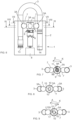
- Figure 1 shows an example of an electronic padlock 1 according to the invention.
- Figure 1 shows a situation, where the electronic padlock is opened and the shackle can be raised even higher than Figure 1 shows.
- the electronic padlock according to the invention comprises a body 2 and a shackle 3.
- the body has latch parts 7, a cam piece 5 and an electronic actuator 4.
- the electronic actuator is arranged to turn the cam piece 5 to release the latch parts 7 from a locking state, and to turn the cam piece 5 to hold the latch parts 7 in the locking state.
- the latch parts 7 prevent the shackle 3 from being moved to open the electronic padlock.
- the locking state is shown in Figure 6 .
- the shackle 3 has holes 3A for the latch parts. In the locking state, the latch parts 7 are partly in the shackle holes 3A, whereby they prevent the shackle from being pulled out in relation to the body 2. The electronic padlock is thus locked.
- the body 2 of the electronic padlock 1 has spaces (such as drillings) for different parts of the padlock. These spaces are not shown in more detail in Figure 1 , for the sake of clarity.
- the electronic padlock also comprises other parts than the ones mentioned above, such as indicators 13, 14, to indicate if the shackle is completely inside the body, whereby the electronic padlock can be locked with the electronic actuator 4.
- the electronic actuator and cam piece are put into the body in the space/drilling reserved for them, and held inside the lock body with a lid part 8.
- the lid part is for example a cylinder equipped with an outer thread, which is locked to the body with a separate locking screw (not shown in the figures).
- the figures do not show all parts of the electronic padlock.
- the figures show the parts, which are necessary for describing the invention.
- the electronic actuator 4 can be directly connected to the cam piece 6, so that the electronic actuator can turn the cam piece.
- the electronic actuator turns the cam piece to open the locking of the electronic padlock or to lock the electronic padlock.
- the electronic padlock can also comprise a separate power transmission part 6 between the electronic actuator 4 and the shaft part 5B.
- the power transmission part 6 transmits the force turning the electronic actuator to the cam piece 5.
- the power transmission part can also comprise other functions. It can for example also functions as a blocking mechanism. The blocking mechanism allows turning of the cam piece with the electronic actuator, but strives to prevent any other turning of the cam piece 5 in relation to the body 2.
- the cam piece 5 comprises a cover part 5A and a shaft part 5B.
- the cover part has a central hole 12 for the shaft part and recesses 10 on the surface of the cover part.
- the shaft part 5B has an axle pin 15, which is set into the central hole 12.
- the shaft part also has a connecting part 19, which is arranged to be in contact with the electronic actuator 4.
- the diameter of the connecting part 19 can be wider than the diameter of the shaft pin, as illustrated in Figure 2 .
- the diameters of both the connecting part 19 and the shaft pin 15 are perpendicular in relation to the longitudinal axis X of the shaft pin.
- the cam piece further comprises a spring 9, which is between the shaft pin 15 and the cover part 5A. The spring is thus also placed in the central hole 12.
- the spring is a coil spring, which is shaped as a torsion spring, but it can also be another type of spring.
- the spring comprises a first end 9A and a second end 9B.
- the first end 9A is arranged to be in contact with the cover part 5A.
- the second end 9B is arranged to be in contact with the shaft part 5B.
- the spring is arranged to transmit turning force of the electronic actuator from the axle pin 15 to the cover part 5A in the direction of said locking state.
- the spring is arranged to transmit the turning force of the electronic actuator, which turns the shaft pin, via the first end 9A of the spring to the cover part 5A to turn it into the locking position.
- the shaft part further comprises at least one protrusion 17 on the surface of the shaft pin 15 and/or on the surface of the connecting part 19.
- This protrusion is arranged to transmit turning force of the electronic actuator from the shaft pin 15 to the cover part 5A to release the latch parts.
- the electronic actuator 4 turns (either directly or via a power transmission part 6) the connecting part 19, the protrusion/protrusions 17, 18 of which transmit the turning force to the cover part 5A.
- the force used for opening the electronic padlock is thus transmitted via at least one protrusion 17, 18 and the force used for locking via the spring 9.
- two protrusions are placed at the base of the shaft pin 15 against the connecting part 19.
- the spring is further arranged to allow turning of the cover part 5A against the turning force of the electronic actuator from the shaft pin 15 to the cover part 5A.
- Such a situation can happen, if simultaneously a jerk is directed at the shackle, which jerk strives to move the shackle to the open position.
- the shackle In the open position, the shackle can be set in the target, so that the target can be locked, when the electronic padlock is locked.
- Figures 3-5 show sectional depictions of the embodiment of Figure 1 . From Figure 3 can be seen how the second end of the spring 9 is arranged against the shaft pin.
- the shaft pin 15 can comprise a groove 16 or a hole for the second end 9B of the spring.
- the groove 16 can split the shaft pin on the side of its free end a part of the way toward the connecting part 19, as shown in Figure 2 . This way, installation of the spring is easy.
- the second end 9B of the spring is in the direction of the diameter of the shaft pin, but it can also be for example in the direction of the longitudinal axis X of the shaft pin, whereby the shaft pin has a hole (such as a drilling) for the second end of the spring.
- the cover part 5A in turn comprises a hole 11 for the first end 9A of the spring.
- the hole has a side surface 11A for transmitting turning force between the end 9A of the spring and the cover part 5A.
- Figure 4 shows how the latch parts 7 are in the recesses 10 in the cover part 5A, when the electronic padlock is open.
- Figures 3 and 5 show the turning direction A, by turning in which direction the shaft pin 15 transmits the turning force of the electronic actuator via the protrusions 17, 18 to the cover part 5A.
- the electronic padlock is opened with the electronic actuator by turning the shaft part 5B and thus also the cover part 5A in the opening turning direction A.
- the spring 9 does thus not transmit turning force.
- Figures 3 and 5 also show a second turning direction K, by turning in which direction the electronic padlock is locked.
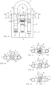
- Figure 6 shows the electronic padlock as locked.
- Figures 7-8 show sectional depictions of the embodiment of Figure 6.
- Figures 6 and 8 show how the latch parts 7 are partly in the holes 3A of the shackle and the recesses 10 in the cover part are not toward the latch parts.
- the cover part 5A holds the latch parts against the holes 3A in the shackle, and the electronic padlock is in the locking state.
- Figures 7 and 9 show the turning direction K toward the locking of the electronic padlock.
- the spring 9 has (via the ends 9A, 9B of the spring) transmitted the turning force from the shaft pin 15 to the cover part 5A.
- the turning force has been transmitted from the electronic actuator 4 to the shaft pin 15.
- the protrusion 17, 18 or protrusions of the shaft part 5B do not transmit turning force in the locking direction K, as can be seen in Figure 9 .
- the central hole 12 comprises at least one recess 12A for said at least one protrusion 17.
- the recess/recesses 12A is/are wider than the protrusion/protrusions 17, 18.
- Figures 7 and 9 also show the opening turning direction A for opening the electronic padlock.
- Figures 10 - 14 show a situation, where the electronic padlock is locked with the electronic actuator 4 by turning the shaft part (and its shaft pin 15) in the turning direction K, whereby also the cover part 5A turns via the spring 9. Simultaneously, a jerk has been directed at the shackle in the direction N, which jerk strives to move the shackle to the open position. Thus, the latch parts 7 strive to move back toward the recesses 10 in the cover part 5A, which in turn turns the cover part in the opposite direction (i.e. the opening direction A) to the direction in which the electronic actuator turns the cover part. A large stress is thus directed at the electronic actuator, which may break it.
- Figure 14 illustrates how the movement of the shackle caused by the jerk moves N1 the latch parts 7 toward the cover part 5A. Via the recesses 10, the force of the jerk turns the cover part in the turning direction A.
- Figure 14 shows the starting phase of the jerk.
- Figures 11 - 13 show how the spring 9 has received the external force (jerk) and allowed the cover part 5A to turn in the turning direction A.
- the recesses 12A of the central hole 12 are designed to allow this turning due to an external force, as Figure 13 illustrates. It is desirable that the width of the recess 12A of the central hole is not wider than the width necessary for the turning of the cover part in the turning direction A against the turning of the electronic actuator in the turning direction K. On the other hand, the recess/recesses 12A of the central hole can also be wider.
- the electronic padlock according to the invention can be implemented in many different ways.
- the connecting part 19 comprises a transmission surface 19A, via which the shaft part 5B is arranged to be in contact with the electronic actuator 4.
- the transmission surface 19A comprises at least one recess and/or protrusion.
- the shapes of the transmission surface can thus have different embodiments.
- the latch parts 7 are balls or pins, the ends of which pins are hemispherical.
- the electronic actuator 4 can be an electric motor or a solenoid. Using an electric motor is usually more straight-forward, but turning the cam piece can be done also with a solenoid. Thus, the electronic actuator 4 has some kind of power transmission to transmit the movement of the solenoid (such as the movement of the pin of the solenoid) into a turning movement.
- the opening and locking of the electronic padlock entering the opening code, lock ready to be locked, locking command) is implemented in an otherwise known manner, so it is not described in further detail in this context.
- the solution according to the invention effectively prevents breaking of the electronic actuator of the electronic padlock, such as the electric motor, if an external force, which pulls the shackle away from the body of the electronic padlock, is directed at the shackle at the closing phase.
- the electronic padlock according to the invention can be realized in many different ways, as can be discerned from the description above.
- the invention is thus not limited to the examples presented herein, but can be implemented in different ways within the scope of the independent claim.
Landscapes
- Physics & Mathematics (AREA)
- Electromagnetism (AREA)
- Switch Cases, Indication, And Locking (AREA)
- Lock And Its Accessories (AREA)
- Electrochromic Elements, Electrophoresis, Or Variable Reflection Or Absorption Elements (AREA)
- Road Repair (AREA)
- Printers Or Recording Devices Using Electromagnetic And Radiation Means (AREA)
- Casings For Electric Apparatus (AREA)
Description
- The invention relates to electronic padlocks. The invention particularly relates to electronic padlocks, in which an electronic actuator is arranged to turn a cam piece in order to release latch parts from a locking state. When the latch parts are released from the locking state, the electronic padlock can be opened.
- Prior art electronic padlocks often use an electronic actuator for opening the locking. The electronic padlock can receive an opening code in different ways, depending on the implementation method. The opening code can be entered in the electronic padlock for example from a mobile phone via a Bluetooth connection or via some other wireless network. RFID technology or NFC technology can also be used. The electronic padlock can also have a keyboard or a touch screen for entering the opening code, or the lock has for example a fingerprint identifier. When the correct opening code has been entered into the electronic padlock, the electronic actuator in the lock releases the locking, whereby the padlock can be opened. When the locking is released, the padlock shackle can be moved from the closed position to the open position, i.e. the padlock can be opened.
- The electronic actuator can for example be an electric motor, which is arranged to turn the cam piece of the padlock. The cam piece is a part, which holds the latch parts against counter holes in the shackle, when the padlock is locked. When the electronic padlock receives the correct opening code, the electronic actuator turns the cam piece (usually 90 degrees), so that the recesses in the cam piece are by the latch parts. Thus, the latch parts can move away from the counter hole in the shackle, i.e. the locking state is released, and the electronic padlock can be opened. When the electronic padlock is locked, the shackle is in the closed position and the electronic actuator turns the cam piece into the locking position, whereby it holds the latch parts against the counter holes in the shackle. The latch parts are normally balls.
- Known electronic padlock solutions, which have an electronic actuator, are presented in publications
WO 2018184070 ,US 2013276487 ,CN 206158371 andWO 2019223522 . - In electronic padlocks like the ones described above, the electronic actuator can break, when it turns the cam piece to lock the electronic padlock. If a jerk is simultaneous directed at the shackle, which jerk strives to move the shackle to the open position, the latch parts start to move back into the recesses in the cam piece, which in turn causes the cam piece to turn against the turning force of the electronic actuator. The turning of the cam piece against the turning direction of the electronic actuator can break the electronic actuator. Buffering arrangements using a spring to avoid damage of an electronic actuator have been disclosed in
WO 2015/049680 A1 . - The object of the invention is to provide an alternative construction of an electronic padlock, which eliminates or at least significantly reduces the possibility of breaking of the electronic actuator of the electronic padlock, when the electronic padlock is being locked. This is achieved in the manner presented in the independent claim. The dependent claims present different embodiments of the invention.
- The electronic padlock according to the invention comprises a
body 2 and ashackle 3. The body haslatch parts 7, acam piece 5 and anelectronic actuator 4. The electronic actuator is arranged to turn thecam piece 5 to release thelatch parts 7 from a locking state, and to turn thecam piece 5 to hold thelatch parts 7 in the locking state. In the locking state, thelatch parts 7 prevent theshackle 3 from being moved to open the electronic padlock. Thecam piece 5 comprises acover part 5A and ashaft part 5B. The cover part has acentral hole 12 for the shaft part and recesses 10 on the surface of the cover part. Theshaft part 5B has ashaft pin 15, which is set into thecentral hole 12. The shaft part also has a connectingpart 19, which is arranged to be in contact with theelectronic actuator 4. The cam piece further comprises a spring 9, which is between theshaft pin 15 and thecover part 5A. The spring comprises afirst end 9A and asecond end 9B. Thefirst end 9A is arranged to be in contact with thecover part 5A. Thesecond end 9B is arranged to be in contact with theshaft part 5B. The spring is arranged to transmit turning force of the electronic actuator from theshaft pin 15 to thecover part 5A in the direction of said locking state. Thecover part 5A comprises ahole 11 for thefirst end 9A of the spring, which hole has aside surface 11A for transmitting turning force between theend 9A of the spring and the cover part. - The shaft part further comprises at least one
protrusion 17 on the surface of theshaft pin 15 and/or on the surface of the connectingpart 19. This protrusion is arranged to transmit turning force of the electronic actuator from theshaft pin 15 to thecover part 5A to release the latch parts. The spring is further arranged to allow turning of thecover part 5A against the turning force of the electronic actuator from theshaft pin 15 to thecover part 5A. - In the following, the invention will be described in more detail with reference to the appended figures, in which
- Figure 1
- shows an example of an electronic padlock according to the invention as opened,
- Figure 2
- shows an example of the cam piece of an electronic padlock according to the invention,
- Figure 3
- shows a section of the example of
Figure 1 , - Figure 4
- shows a second section of the example of
Figure 1 , - Figure 5
- shows a third section of the example of
Figure 1 , - Figure 6
- shows an example of an electronic padlock according to the invention as locked,
- Figure 7
- shows a section of the example of
Figure 6 , - Figure 8
- shows a second section of the example of
Figure 6 , - Figure 9
- shows a third section of the example of
Figure 6 , - Figure 10
- shows an example of an electronic padlock according to the invention, when an outward pulling jerk has been directed at the shackle when locking the electronic padlock,
- Figure 11
- shows a section of the example of
Figure 10 , - Figure 12
- shows a second section of the example of
Figure 10 , - Figure 13
- shows a third section of the example of
Figure 10 , and - Figure 14
- shows an illustrative example of the electronic padlock according to the invention at the beginning of a jerk directed at the shackle.
-
Figure 1 shows an example of anelectronic padlock 1 according to the invention.Figure 1 shows a situation, where the electronic padlock is opened and the shackle can be raised even higher thanFigure 1 shows. - The electronic padlock according to the invention comprises a
body 2 and ashackle 3. The body haslatch parts 7, acam piece 5 and anelectronic actuator 4. The electronic actuator is arranged to turn thecam piece 5 to release thelatch parts 7 from a locking state, and to turn thecam piece 5 to hold thelatch parts 7 in the locking state. In the locking state, thelatch parts 7 prevent theshackle 3 from being moved to open the electronic padlock. The locking state is shown inFigure 6 . Theshackle 3 hasholes 3A for the latch parts. In the locking state, thelatch parts 7 are partly in the shackle holes 3A, whereby they prevent the shackle from being pulled out in relation to thebody 2. The electronic padlock is thus locked. - The
body 2 of theelectronic padlock 1 has spaces (such as drillings) for different parts of the padlock. These spaces are not shown in more detail inFigure 1 , for the sake of clarity. The electronic padlock also comprises other parts than the ones mentioned above, such asindicators electronic actuator 4. The electronic actuator and cam piece are put into the body in the space/drilling reserved for them, and held inside the lock body with alid part 8. The lid part is for example a cylinder equipped with an outer thread, which is locked to the body with a separate locking screw (not shown in the figures). The figures do not show all parts of the electronic padlock. The figures show the parts, which are necessary for describing the invention. - The
electronic actuator 4 can be directly connected to thecam piece 6, so that the electronic actuator can turn the cam piece. The electronic actuator turns the cam piece to open the locking of the electronic padlock or to lock the electronic padlock. The electronic padlock can also comprise a separatepower transmission part 6 between theelectronic actuator 4 and theshaft part 5B. Thus, thepower transmission part 6 transmits the force turning the electronic actuator to thecam piece 5. The power transmission part can also comprise other functions. It can for example also functions as a blocking mechanism. The blocking mechanism allows turning of the cam piece with the electronic actuator, but strives to prevent any other turning of thecam piece 5 in relation to thebody 2. - An embodiment of the
cam piece 5 according to the invention is shown inFigure 2 . Thecam piece 5 comprises acover part 5A and ashaft part 5B. The cover part has acentral hole 12 for the shaft part and recesses 10 on the surface of the cover part. Theshaft part 5B has anaxle pin 15, which is set into thecentral hole 12. The shaft part also has a connectingpart 19, which is arranged to be in contact with theelectronic actuator 4. The diameter of the connectingpart 19 can be wider than the diameter of the shaft pin, as illustrated inFigure 2 . The diameters of both the connectingpart 19 and theshaft pin 15 are perpendicular in relation to the longitudinal axis X of the shaft pin. The cam piece further comprises a spring 9, which is between theshaft pin 15 and thecover part 5A. The spring is thus also placed in thecentral hole 12. In the figures the spring is a coil spring, which is shaped as a torsion spring, but it can also be another type of spring. - The spring comprises a
first end 9A and asecond end 9B. Thefirst end 9A is arranged to be in contact with thecover part 5A. Thesecond end 9B is arranged to be in contact with theshaft part 5B. The spring is arranged to transmit turning force of the electronic actuator from theaxle pin 15 to thecover part 5A in the direction of said locking state. In other words, the spring is arranged to transmit the turning force of the electronic actuator, which turns the shaft pin, via thefirst end 9A of the spring to thecover part 5A to turn it into the locking position. - The shaft part further comprises at least one
protrusion 17 on the surface of theshaft pin 15 and/or on the surface of the connectingpart 19. This protrusion is arranged to transmit turning force of the electronic actuator from theshaft pin 15 to thecover part 5A to release the latch parts. In other words, when the locking of the electronic padlock is opened, theelectronic actuator 4 turns (either directly or via a power transmission part 6) the connectingpart 19, the protrusion/protrusions cover part 5A. The force used for opening the electronic padlock is thus transmitted via at least oneprotrusion Figure 2 , two protrusions are placed at the base of theshaft pin 15 against the connectingpart 19. - The spring is further arranged to allow turning of the
cover part 5A against the turning force of the electronic actuator from theshaft pin 15 to thecover part 5A. Such a situation can happen, if simultaneously a jerk is directed at the shackle, which jerk strives to move the shackle to the open position. In the open position, the shackle can be set in the target, so that the target can be locked, when the electronic padlock is locked. -
Figures 3-5 show sectional depictions of the embodiment ofFigure 1 . FromFigure 3 can be seen how the second end of the spring 9 is arranged against the shaft pin. Theshaft pin 15 can comprise agroove 16 or a hole for thesecond end 9B of the spring. Thegroove 16 can split the shaft pin on the side of its free end a part of the way toward the connectingpart 19, as shown inFigure 2 . This way, installation of the spring is easy. In the embodiment of the figures, thesecond end 9B of the spring is in the direction of the diameter of the shaft pin, but it can also be for example in the direction of the longitudinal axis X of the shaft pin, whereby the shaft pin has a hole (such as a drilling) for the second end of the spring. Thecover part 5A in turn comprises ahole 11 for thefirst end 9A of the spring. The hole has aside surface 11A for transmitting turning force between theend 9A of the spring and thecover part 5A. -
Figure 4 shows how thelatch parts 7 are in therecesses 10 in thecover part 5A, when the electronic padlock is open.Figures 3 and 5 show the turning direction A, by turning in which direction theshaft pin 15 transmits the turning force of the electronic actuator via theprotrusions cover part 5A. In other words, the electronic padlock is opened with the electronic actuator by turning theshaft part 5B and thus also thecover part 5A in the opening turning direction A. The spring 9 does thus not transmit turning force.Figures 3 and 5 also show a second turning direction K, by turning in which direction the electronic padlock is locked. -
Figure 6 shows the electronic padlock as locked.Figures 7-8 show sectional depictions of the embodiment ofFigure 6. Figures 6 and 8 show how thelatch parts 7 are partly in theholes 3A of the shackle and therecesses 10 in the cover part are not toward the latch parts. Thus, thecover part 5A holds the latch parts against theholes 3A in the shackle, and the electronic padlock is in the locking state.Figures 7 and 9 show the turning direction K toward the locking of the electronic padlock. As can be seen, the spring 9 has (via theends shaft pin 15 to thecover part 5A. As was already noted before, the turning force has been transmitted from theelectronic actuator 4 to theshaft pin 15. Theprotrusion shaft part 5B do not transmit turning force in the locking direction K, as can be seen inFigure 9 . Thecentral hole 12 comprises at least onerecess 12A for said at least oneprotrusion 17. The recess/recesses 12A is/are wider than the protrusion/protrusions Figures 7 and 9 also show the opening turning direction A for opening the electronic padlock. -
Figures 10 - 14 show a situation, where the electronic padlock is locked with theelectronic actuator 4 by turning the shaft part (and its shaft pin 15) in the turning direction K, whereby also thecover part 5A turns via the spring 9. Simultaneously, a jerk has been directed at the shackle in the direction N, which jerk strives to move the shackle to the open position. Thus, thelatch parts 7 strive to move back toward therecesses 10 in thecover part 5A, which in turn turns the cover part in the opposite direction (i.e. the opening direction A) to the direction in which the electronic actuator turns the cover part. A large stress is thus directed at the electronic actuator, which may break it. - The spring 9, however, allows the cover part to turn in such a situation in the opening direction A, even though the shaft pin turns as turned by the electronic actuator in the locking direction K. Thus, only a part of the force of the jerk is directed at the electronic actuator, because a part of the force goes into tensing the spring 9.
Figures 11-13 show this situation, where the spring 9 is tensed due to a jerk or other external force and thecover part 5A has turned in the turning direction A against the turning direction K of the electronic actuator. -
Figure 14 illustrates how the movement of the shackle caused by the jerk moves N1 thelatch parts 7 toward thecover part 5A. Via therecesses 10, the force of the jerk turns the cover part in the turning direction A.Figure 14 shows the starting phase of the jerk.Figures 11 - 13 show how the spring 9 has received the external force (jerk) and allowed thecover part 5A to turn in the turning direction A. Therecesses 12A of thecentral hole 12 are designed to allow this turning due to an external force, asFigure 13 illustrates. It is desirable that the width of therecess 12A of the central hole is not wider than the width necessary for the turning of the cover part in the turning direction A against the turning of the electronic actuator in the turning direction K. On the other hand, the recess/recesses 12A of the central hole can also be wider. - The electronic padlock according to the invention can be implemented in many different ways. For example, there can be various embodiments of the parts of the
cam piece 5. AsFigure 2 illustrates, the connectingpart 19 comprises atransmission surface 19A, via which theshaft part 5B is arranged to be in contact with theelectronic actuator 4. Thetransmission surface 19A comprises at least one recess and/or protrusion. The shapes of the transmission surface can thus have different embodiments. - The
latch parts 7 are balls or pins, the ends of which pins are hemispherical. Theelectronic actuator 4 can be an electric motor or a solenoid. Using an electric motor is usually more straight-forward, but turning the cam piece can be done also with a solenoid. Thus, theelectronic actuator 4 has some kind of power transmission to transmit the movement of the solenoid (such as the movement of the pin of the solenoid) into a turning movement. The opening and locking of the electronic padlock (entering the opening code, lock ready to be locked, locking command) is implemented in an otherwise known manner, so it is not described in further detail in this context. - The solution according to the invention effectively prevents breaking of the electronic actuator of the electronic padlock, such as the electric motor, if an external force, which pulls the shackle away from the body of the electronic padlock, is directed at the shackle at the closing phase.
- The electronic padlock according to the invention can be realized in many different ways, as can be discerned from the description above. The invention is thus not limited to the examples presented herein, but can be implemented in different ways within the scope of the independent claim.
Claims (8)
- An electronic padlock, which comprises a body (2) and a shackle (3), which body has latch parts (7), a cam piece (5) and an electronic actuator (4), which electronic actuator is arranged to turn the cam piece (5) to release the latch parts (7) from the locking state and to turn the cam piece (5) to hold the latch parts (7) in the locking state, in which locking state the latch parts (7) prevent the moving of the shackle (3) to open the electronic padlock, characterized in that the cam piece (5) comprises a cover part (5A) and a shaft part (5B), which cover part has a central hole (12) for the shaft part and recesses (10) on the surface of the cover part, and which shaft part (5B) has a shaft pin (15), which is set in the central hole (12), and a connecting part (19), which is arranged to be in contact with the electronic actuator (4), which cam piece additionally comprises a spring (9) between the shaft pin (15) and the cover part (5A), which spring comprises a first end (9A) and a second end (9B), which first end (9A) is arranged to be in contact with the cover part (5A) and which second end is arranged to be in contact with the shaft part (5B), which spring is arranged to transmit turning force of the electronic actuator from the shaft pin (15) to the cover part (5A) in the direction of said locking state andwhich shaft part further comprises at least one protrusion (17) on the surface of the shaft pin (15) and/or on the surface of the connecting part (19), which protrusion is arranged to transmit turning force of the electronic actuator from the shaft pin (15) to the cover part (5A) to release the latch parts, andwhich spring is further arranged to allow turning of the cover part (5A) against the turning force of the electronic actuator if the spring is tensioned due to external force, andthe central hole (12) comprises at least one recess (12A) for said at least one protrusion (17), which recess (12A) is wider than the protrusion (17), andthe cover part (5A) comprises a hole (11) for the first end (9A) of the spring, which hole has a side surface (11A) for transmitting turning force between the end (9A) of the spring and the cover part.
- The electronic padlock according to claim 1, characterized in that the shaft pin (15) comprises a groove (16) or hole for the second end (9B) of the spring.
- The electronic padlock according to claim 2, characterized in that the connecting part (19) comprises a transmission surface (19A), via which the shaft part (5B) is arranged to be in contact with the electronic actuator (4).
- The electronic padlock according to claim 3, characterized in that the transmission surface (19A) comprises at least one recess and/or protrusion.
- The electronic padlock according to claim 4, characterized in that the diameter of the connecting part (19) is wider than the diameter of the shaft pin (15), while both diameters are perpendicular to the longitudinal axis of the shaft pin.
- The electronic padlock according to claim 5, characterized in that the electronic padlock comprises a separate power transmission part (6) between the electronic actuator (4) and the connecting part (19).
- The electronic padlock according to claim 6, characterized in that the latch parts (7) are balls or pins, the ends of which pins are hemispherical.
- The electronic padlock according to claim 7, characterized in that the electronic actuator (4) is an electric motor or a solenoid.
Applications Claiming Priority (2)
| Application Number | Priority Date | Filing Date | Title |
|---|---|---|---|
| FI20205701A FI129016B (en) | 2020-07-01 | 2020-07-01 | Electric padlock |
| PCT/FI2021/050452 WO2022003236A1 (en) | 2020-07-01 | 2021-06-16 | Electronic padlock |
Publications (3)
| Publication Number | Publication Date |
|---|---|
| EP4176147A1 EP4176147A1 (en) | 2023-05-10 |
| EP4176147B1 true EP4176147B1 (en) | 2024-12-04 |
| EP4176147C0 EP4176147C0 (en) | 2024-12-04 |
Family
ID=75866303
Family Applications (1)
| Application Number | Title | Priority Date | Filing Date |
|---|---|---|---|
| EP21739409.7A Active EP4176147B1 (en) | 2020-07-01 | 2021-06-16 | Electronic padlock |
Country Status (13)
| Country | Link |
|---|---|
| US (1) | US11708707B2 (en) |
| EP (1) | EP4176147B1 (en) |
| JP (1) | JP7404560B2 (en) |
| CN (1) | CN116075621B (en) |
| AU (1) | AU2021298903B2 (en) |
| BR (1) | BR112022026020A2 (en) |
| CA (1) | CA3183156C (en) |
| CO (1) | CO2023000752A2 (en) |
| FI (1) | FI129016B (en) |
| IL (1) | IL299539B2 (en) |
| MX (1) | MX2022016186A (en) |
| WO (1) | WO2022003236A1 (en) |
| ZA (1) | ZA202213547B (en) |
Families Citing this family (3)
| Publication number | Priority date | Publication date | Assignee | Title |
|---|---|---|---|---|
| DE102019113184B4 (en) * | 2019-05-17 | 2021-08-12 | ABUS August Bremicker Söhne Kommanditgesellschaft | Mobile electronic lock |
| USD1115491S1 (en) * | 2024-09-18 | 2026-03-03 | Master Lock Company Llc | Padlock |
| USD1130068S1 (en) * | 2024-09-18 | 2026-06-16 | Master Lock Company Llc | Padlock |
Citations (1)
| Publication number | Priority date | Publication date | Assignee | Title |
|---|---|---|---|---|
| WO2019200554A1 (en) * | 2018-04-18 | 2019-10-24 | 东莞清溪光华制锁厂有限公司 | Electronic padlock |
Family Cites Families (40)
| Publication number | Priority date | Publication date | Assignee | Title |
|---|---|---|---|---|
| US2132201A (en) * | 1935-06-27 | 1938-10-04 | Allman Joseph | Padlock |
| SE328804B (en) * | 1967-08-29 | 1970-09-21 | Waertsilae Oy Ab | |
| US3793856A (en) * | 1972-10-13 | 1974-02-26 | Junkunc Bros American Lock Co | Padlock and key cylinder release |
| US3952559A (en) * | 1974-05-10 | 1976-04-27 | Long Manufacturing Co., Inc. | Exposed shackle padlock |
| JPS5838126Y2 (en) * | 1980-08-27 | 1983-08-29 | セブンロツク株式会社 | padlock |
| US4763496A (en) * | 1987-05-27 | 1988-08-16 | Sargent & Greenleaf, Inc. | High security changeable key cylinder type shackle padlock |
| US4938039A (en) * | 1989-05-09 | 1990-07-03 | Tzung I Lo | Actuating mechanism for padlock |
| JPH10184154A (en) * | 1996-12-24 | 1998-07-14 | Komori Kosakusho:Kk | Padlock with two locking methods |
| CA2199217A1 (en) * | 1997-03-05 | 1998-09-05 | Michael Reed Thomas | Digital electronic lock |
| US20030159479A1 (en) * | 2002-02-05 | 2003-08-28 | Peter Kajuch | Multi-function locking cam for locks |
| US6761051B1 (en) * | 2003-02-27 | 2004-07-13 | Ez Trend Technology Co., Ltd. | Electric padlock |
| CN1961129A (en) * | 2004-04-29 | 2007-05-09 | 塞莱斯蒂亚股份有限公司 | Padlock with key retention or non-retention (and snap - lock) facility |
| US20060288744A1 (en) * | 2005-06-28 | 2006-12-28 | William Smith | Alarm lock |
| CN101029548B (en) | 2006-03-02 | 2011-02-09 | 川斯海洋集团有限公司 | Padlock with quick shackle change |
| US8225629B2 (en) * | 2008-04-18 | 2012-07-24 | Ingersoll Rand Company | Portable lock with electronic lock actuator |
| JP5296650B2 (en) | 2009-09-28 | 2013-09-25 | 東海理研株式会社 | Electronic padlock |
| MX2013000526A (en) * | 2010-07-15 | 2013-03-22 | Master Lock Co | PADLOCK. |
| WO2013049533A1 (en) * | 2011-09-30 | 2013-04-04 | Master Lock Company Llc | Multiple mode locking arrangements |
| FI124681B (en) * | 2011-10-28 | 2014-12-15 | Abloy Oy | Padlock |
| CA2855134A1 (en) * | 2011-11-11 | 2013-05-16 | Master Lock Company Llc | Battery access and power supply arrangements |
| US8806905B2 (en) * | 2012-04-19 | 2014-08-19 | Master Lock Company Llc | Padlock assembly |
| US8850858B2 (en) * | 2012-12-06 | 2014-10-07 | Master Lock Company Llc | Lock subassembly |
| US8904833B1 (en) * | 2013-07-22 | 2014-12-09 | Federal Lock Co., Ltd. | Lock with replaceable shackle |
| WO2015049680A1 (en) * | 2013-10-02 | 2015-04-09 | Knock N'lock Ltd. | Sliding bolt padlock |
| US9109379B1 (en) * | 2014-08-12 | 2015-08-18 | Dog & Bone Holdings Pty Ltd | Keyless padlock, system and method of use |
| US20170268260A1 (en) * | 2015-04-24 | 2017-09-21 | My Touch Id, Llc | Replacement Shackle for Portable Lock |
| US9574377B2 (en) * | 2015-04-24 | 2017-02-21 | MyTouch ID, LLC | Replacement shackle for portable lock |
| CN205531813U (en) * | 2015-12-11 | 2016-08-31 | 珠海优特电力科技股份有限公司 | Electronic padlock |
| US10267062B2 (en) * | 2015-12-11 | 2019-04-23 | The Sun Lock Company, Ltd. | Electronic combination lock with different levels of access control |
| US10614641B2 (en) * | 2015-12-11 | 2020-04-07 | The Sun Lock Company, Ltd. | Electronic combination lock with different levels of access control |
| DE112015007187T5 (en) * | 2015-12-15 | 2018-08-30 | Assa Abloy Japan Co., Ltd. | padlock |
| CN206158371U (en) | 2016-10-09 | 2017-05-10 | 浙江浦江梅花锁业集团有限公司 | Electronic lock courage |
| US10337209B2 (en) * | 2016-10-25 | 2019-07-02 | Leslie Ho Leung Chow | Motor with mounted printed circuit board for electronic lock |
| EP3607160B1 (en) | 2017-04-05 | 2024-02-21 | Assa Abloy Australia Pty Limited | Electronically controlled padlock |
| US10221592B2 (en) * | 2017-06-23 | 2019-03-05 | Master Lock Company Llc | Padlock assembly |
| CN107524357B (en) | 2017-09-12 | 2023-01-31 | 珠海耀阳电子科技有限公司 | Padlock |
| CN208396493U (en) | 2018-05-21 | 2019-01-18 | 浙江浦江梅花锁业集团有限公司 | A kind of electronic lock |
| US11346134B2 (en) * | 2019-02-06 | 2022-05-31 | Brady Worldwide, Inc. | Lock with integrated cam |
| CN110107165A (en) * | 2019-05-15 | 2019-08-09 | 宁波生久柜锁有限公司 | Intelligent padlock |
| CN110439377B (en) * | 2019-08-23 | 2024-05-31 | 珠海优特电力科技股份有限公司 | Electronic lock cylinder and lockset thereof |
-
2020
- 2020-07-01 FI FI20205701A patent/FI129016B/en active IP Right Grant
-
2021
- 2021-06-16 CN CN202180047137.0A patent/CN116075621B/en active Active
- 2021-06-16 WO PCT/FI2021/050452 patent/WO2022003236A1/en not_active Ceased
- 2021-06-16 CA CA3183156A patent/CA3183156C/en active Active
- 2021-06-16 EP EP21739409.7A patent/EP4176147B1/en active Active
- 2021-06-16 US US18/014,278 patent/US11708707B2/en active Active
- 2021-06-16 JP JP2022575404A patent/JP7404560B2/en active Active
- 2021-06-16 AU AU2021298903A patent/AU2021298903B2/en active Active
- 2021-06-16 MX MX2022016186A patent/MX2022016186A/en unknown
- 2021-06-16 BR BR112022026020A patent/BR112022026020A2/en unknown
- 2021-06-16 IL IL299539A patent/IL299539B2/en unknown
-
2022
- 2022-12-14 ZA ZA2022/13547A patent/ZA202213547B/en unknown
-
2023
- 2023-01-24 CO CONC2023/0000752A patent/CO2023000752A2/en unknown
Patent Citations (1)
| Publication number | Priority date | Publication date | Assignee | Title |
|---|---|---|---|---|
| WO2019200554A1 (en) * | 2018-04-18 | 2019-10-24 | 东莞清溪光华制锁厂有限公司 | Electronic padlock |
Also Published As
| Publication number | Publication date |
|---|---|
| AU2021298903B2 (en) | 2026-07-30 |
| US11708707B2 (en) | 2023-07-25 |
| CN116075621B (en) | 2024-02-02 |
| FI129016B (en) | 2021-05-14 |
| US20230193658A1 (en) | 2023-06-22 |
| MX2022016186A (en) | 2023-02-13 |
| JP7404560B2 (en) | 2023-12-25 |
| ZA202213547B (en) | 2024-06-26 |
| IL299539A (en) | 2023-02-01 |
| EP4176147C0 (en) | 2024-12-04 |
| WO2022003236A1 (en) | 2022-01-06 |
| EP4176147A1 (en) | 2023-05-10 |
| IL299539B1 (en) | 2023-10-01 |
| CO2023000752A2 (en) | 2023-02-16 |
| CA3183156A1 (en) | 2022-01-06 |
| JP2023532420A (en) | 2023-07-28 |
| CA3183156C (en) | 2023-09-26 |
| FI20205701A1 (en) | 2021-05-14 |
| CN116075621A (en) | 2023-05-05 |
| IL299539B2 (en) | 2024-02-01 |
| AU2021298903A1 (en) | 2023-02-02 |
| BR112022026020A2 (en) | 2023-01-17 |
Similar Documents
| Publication | Publication Date | Title |
|---|---|---|
| US11708707B2 (en) | Electronic padlock | |
| US8375753B2 (en) | Solenoid-operated electromechanical lock | |
| US10533345B2 (en) | Electronic locking device | |
| CA2419756C (en) | Electromechanical cylinder lock-key-combination | |
| EP4150177B1 (en) | Electronic padlock | |
| US20100050715A1 (en) | Magnetic coded lock mechanism | |
| HK40087502A (en) | Electronic padlock | |
| HK40087502B (en) | Electronic padlock | |
| US11428029B2 (en) | Collet latch | |
| EA002716B1 (en) | Cylinder lock combined with a magnetic pin and a non-magnetic pin | |
| CN210888411U (en) | Unlocking mechanism and lock | |
| EP2450507B1 (en) | Lock protection for a cylinder lock | |
| GB2575164A (en) | An electronic locking device | |
| HK40082553B (en) | Electronic padlock | |
| HK40082553A (en) | Electronic padlock | |
| EP3578743A1 (en) | An electronic locking device | |
| AU2024310939A1 (en) | Lock arrangement | |
| GB2588170A (en) | A component for use in a locking device | |
| JP2008075273A (en) | Cylinder lock |
Legal Events
| Date | Code | Title | Description |
|---|---|---|---|
| STAA | Information on the status of an ep patent application or granted ep patent |
Free format text: STATUS: UNKNOWN |
|
| STAA | Information on the status of an ep patent application or granted ep patent |
Free format text: STATUS: THE INTERNATIONAL PUBLICATION HAS BEEN MADE |
|
| PUAI | Public reference made under article 153(3) epc to a published international application that has entered the european phase |
Free format text: ORIGINAL CODE: 0009012 |
|
| STAA | Information on the status of an ep patent application or granted ep patent |
Free format text: STATUS: REQUEST FOR EXAMINATION WAS MADE |
|
| 17P | Request for examination filed |
Effective date: 20230111 |
|
| AK | Designated contracting states |
Kind code of ref document: A1 Designated state(s): AL AT BE BG CH CY CZ DE DK EE ES FI FR GB GR HR HU IE IS IT LI LT LU LV MC MK MT NL NO PL PT RO RS SE SI SK SM TR |
|
| REG | Reference to a national code |
Ref country code: HK Ref legal event code: DE Ref document number: 40087502 Country of ref document: HK |
|
| DAV | Request for validation of the european patent (deleted) | ||
| DAX | Request for extension of the european patent (deleted) | ||
| GRAP | Despatch of communication of intention to grant a patent |
Free format text: ORIGINAL CODE: EPIDOSNIGR1 |
|
| STAA | Information on the status of an ep patent application or granted ep patent |
Free format text: STATUS: GRANT OF PATENT IS INTENDED |
|
| INTG | Intention to grant announced |
Effective date: 20240206 |
|
| GRAJ | Information related to disapproval of communication of intention to grant by the applicant or resumption of examination proceedings by the epo deleted |
Free format text: ORIGINAL CODE: EPIDOSDIGR1 |
|
| STAA | Information on the status of an ep patent application or granted ep patent |
Free format text: STATUS: REQUEST FOR EXAMINATION WAS MADE |
|
| GRAP | Despatch of communication of intention to grant a patent |
Free format text: ORIGINAL CODE: EPIDOSNIGR1 |
|
| STAA | Information on the status of an ep patent application or granted ep patent |
Free format text: STATUS: GRANT OF PATENT IS INTENDED |
|
| INTC | Intention to grant announced (deleted) | ||
| INTG | Intention to grant announced |
Effective date: 20240625 |
|
| GRAS | Grant fee paid |
Free format text: ORIGINAL CODE: EPIDOSNIGR3 |
|
| GRAA | (expected) grant |
Free format text: ORIGINAL CODE: 0009210 |
|
| STAA | Information on the status of an ep patent application or granted ep patent |
Free format text: STATUS: THE PATENT HAS BEEN GRANTED |
|
| AK | Designated contracting states |
Kind code of ref document: B1 Designated state(s): AL AT BE BG CH CY CZ DE DK EE ES FI FR GB GR HR HU IE IS IT LI LT LU LV MC MK MT NL NO PL PT RO RS SE SI SK SM TR |
|
| REG | Reference to a national code |
Ref country code: CH Ref legal event code: EP |
|
| REG | Reference to a national code |
Ref country code: DE Ref legal event code: R096 Ref document number: 602021022889 Country of ref document: DE |
|
| REG | Reference to a national code |
Ref country code: IE Ref legal event code: FG4D |
|
| U01 | Request for unitary effect filed |
Effective date: 20241217 |
|
| U07 | Unitary effect registered |
Designated state(s): AT BE BG DE DK EE FI FR IT LT LU LV MT NL PT RO SE SI Effective date: 20250110 |
|
| PG25 | Lapsed in a contracting state [announced via postgrant information from national office to epo] |
Ref country code: HR Free format text: LAPSE BECAUSE OF FAILURE TO SUBMIT A TRANSLATION OF THE DESCRIPTION OR TO PAY THE FEE WITHIN THE PRESCRIBED TIME-LIMIT Effective date: 20241204 |
|
| PG25 | Lapsed in a contracting state [announced via postgrant information from national office to epo] |
Ref country code: ES Free format text: LAPSE BECAUSE OF FAILURE TO SUBMIT A TRANSLATION OF THE DESCRIPTION OR TO PAY THE FEE WITHIN THE PRESCRIBED TIME-LIMIT Effective date: 20241204 |
|
| PG25 | Lapsed in a contracting state [announced via postgrant information from national office to epo] |
Ref country code: NO Free format text: LAPSE BECAUSE OF FAILURE TO SUBMIT A TRANSLATION OF THE DESCRIPTION OR TO PAY THE FEE WITHIN THE PRESCRIBED TIME-LIMIT Effective date: 20250304 |
|
| PG25 | Lapsed in a contracting state [announced via postgrant information from national office to epo] |
Ref country code: GR Free format text: LAPSE BECAUSE OF FAILURE TO SUBMIT A TRANSLATION OF THE DESCRIPTION OR TO PAY THE FEE WITHIN THE PRESCRIBED TIME-LIMIT Effective date: 20250305 |
|
| PG25 | Lapsed in a contracting state [announced via postgrant information from national office to epo] |
Ref country code: RS Free format text: LAPSE BECAUSE OF FAILURE TO SUBMIT A TRANSLATION OF THE DESCRIPTION OR TO PAY THE FEE WITHIN THE PRESCRIBED TIME-LIMIT Effective date: 20250304 |
|
| U20 | Renewal fee for the european patent with unitary effect paid |
Year of fee payment: 5 Effective date: 20250522 |
|
| PG25 | Lapsed in a contracting state [announced via postgrant information from national office to epo] |
Ref country code: SM Free format text: LAPSE BECAUSE OF FAILURE TO SUBMIT A TRANSLATION OF THE DESCRIPTION OR TO PAY THE FEE WITHIN THE PRESCRIBED TIME-LIMIT Effective date: 20241204 |
|
| PG25 | Lapsed in a contracting state [announced via postgrant information from national office to epo] |
Ref country code: PL Free format text: LAPSE BECAUSE OF FAILURE TO SUBMIT A TRANSLATION OF THE DESCRIPTION OR TO PAY THE FEE WITHIN THE PRESCRIBED TIME-LIMIT Effective date: 20241204 |
|
| PG25 | Lapsed in a contracting state [announced via postgrant information from national office to epo] |
Ref country code: IS Free format text: LAPSE BECAUSE OF FAILURE TO SUBMIT A TRANSLATION OF THE DESCRIPTION OR TO PAY THE FEE WITHIN THE PRESCRIBED TIME-LIMIT Effective date: 20250404 |
|
| PG25 | Lapsed in a contracting state [announced via postgrant information from national office to epo] |
Ref country code: SK Free format text: LAPSE BECAUSE OF FAILURE TO SUBMIT A TRANSLATION OF THE DESCRIPTION OR TO PAY THE FEE WITHIN THE PRESCRIBED TIME-LIMIT Effective date: 20241204 |
|
| PG25 | Lapsed in a contracting state [announced via postgrant information from national office to epo] |
Ref country code: CZ Free format text: LAPSE BECAUSE OF FAILURE TO SUBMIT A TRANSLATION OF THE DESCRIPTION OR TO PAY THE FEE WITHIN THE PRESCRIBED TIME-LIMIT Effective date: 20241204 |
|
| PLBE | No opposition filed within time limit |
Free format text: ORIGINAL CODE: 0009261 |
|
| STAA | Information on the status of an ep patent application or granted ep patent |
Free format text: STATUS: NO OPPOSITION FILED WITHIN TIME LIMIT |
|
| REG | Reference to a national code |
Ref country code: CH Ref legal event code: L10 Free format text: ST27 STATUS EVENT CODE: U-0-0-L10-L00 (AS PROVIDED BY THE NATIONAL OFFICE) Effective date: 20251015 |
|
| 26N | No opposition filed |
Effective date: 20250905 |
|
| REG | Reference to a national code |
Ref country code: CH Ref legal event code: H13 Free format text: ST27 STATUS EVENT CODE: U-0-0-H10-H13 (AS PROVIDED BY THE NATIONAL OFFICE) Effective date: 20260127 |
|
| PG25 | Lapsed in a contracting state [announced via postgrant information from national office to epo] |
Ref country code: MC Free format text: LAPSE BECAUSE OF FAILURE TO SUBMIT A TRANSLATION OF THE DESCRIPTION OR TO PAY THE FEE WITHIN THE PRESCRIBED TIME-LIMIT Effective date: 20241204 |
|
| GBPC | Gb: european patent ceased through non-payment of renewal fee |
Effective date: 20250616 |
|
| PG25 | Lapsed in a contracting state [announced via postgrant information from national office to epo] |
Ref country code: GB Free format text: LAPSE BECAUSE OF NON-PAYMENT OF DUE FEES Effective date: 20250616 |
|
| PG25 | Lapsed in a contracting state [announced via postgrant information from national office to epo] |
Ref country code: IE Free format text: LAPSE BECAUSE OF NON-PAYMENT OF DUE FEES Effective date: 20250616 |
|
| PG25 | Lapsed in a contracting state [announced via postgrant information from national office to epo] |
Ref country code: CH Free format text: LAPSE BECAUSE OF NON-PAYMENT OF DUE FEES Effective date: 20250630 |
|
| U20 | Renewal fee for the european patent with unitary effect paid |
Year of fee payment: 6 Effective date: 20260521 |
|
| PG25 | Lapsed in a contracting state [announced via postgrant information from national office to epo] |
Ref country code: CY Free format text: LAPSE BECAUSE OF FAILURE TO SUBMIT A TRANSLATION OF THE DESCRIPTION OR TO PAY THE FEE WITHIN THE PRESCRIBED TIME-LIMIT Effective date: 20241204 |