EP4175913B1 - Cartridge extraction unit for water purifier - Google Patents
Cartridge extraction unit for water purifier Download PDFInfo
- Publication number
- EP4175913B1 EP4175913B1 EP21740245.2A EP21740245A EP4175913B1 EP 4175913 B1 EP4175913 B1 EP 4175913B1 EP 21740245 A EP21740245 A EP 21740245A EP 4175913 B1 EP4175913 B1 EP 4175913B1
- Authority
- EP
- European Patent Office
- Prior art keywords
- cartridge
- seat
- lever
- chamber
- receiving chamber
- Prior art date
- Legal status (The legal status is an assumption and is not a legal conclusion. Google has not performed a legal analysis and makes no representation as to the accuracy of the status listed.)
- Active
Links
Images


Classifications
-
- A—HUMAN NECESSITIES
- A47—FURNITURE; DOMESTIC ARTICLES OR APPLIANCES; COFFEE MILLS; SPICE MILLS; SUCTION CLEANERS IN GENERAL
- A47J—KITCHEN EQUIPMENT; COFFEE MILLS; SPICE MILLS; APPARATUS FOR MAKING BEVERAGES
- A47J31/00—Apparatus for making beverages
- A47J31/40—Beverage-making apparatus with dispensing means for adding a measured quantity of ingredients, e.g. coffee, water, sugar, cocoa, milk, tea
-
- A—HUMAN NECESSITIES
- A47—FURNITURE; DOMESTIC ARTICLES OR APPLIANCES; COFFEE MILLS; SPICE MILLS; SUCTION CLEANERS IN GENERAL
- A47J—KITCHEN EQUIPMENT; COFFEE MILLS; SPICE MILLS; APPARATUS FOR MAKING BEVERAGES
- A47J31/00—Apparatus for making beverages
- A47J31/44—Parts or details or accessories of beverage-making apparatus
-
- A—HUMAN NECESSITIES
- A47—FURNITURE; DOMESTIC ARTICLES OR APPLIANCES; COFFEE MILLS; SPICE MILLS; SUCTION CLEANERS IN GENERAL
- A47J—KITCHEN EQUIPMENT; COFFEE MILLS; SPICE MILLS; APPARATUS FOR MAKING BEVERAGES
- A47J31/00—Apparatus for making beverages
- A47J31/44—Parts or details or accessories of beverage-making apparatus
- A47J31/46—Dispensing spouts, pumps, drain valves or like liquid transporting devices
-
- A—HUMAN NECESSITIES
- A47—FURNITURE; DOMESTIC ARTICLES OR APPLIANCES; COFFEE MILLS; SPICE MILLS; SUCTION CLEANERS IN GENERAL
- A47J—KITCHEN EQUIPMENT; COFFEE MILLS; SPICE MILLS; APPARATUS FOR MAKING BEVERAGES
- A47J31/00—Apparatus for making beverages
- A47J31/44—Parts or details or accessories of beverage-making apparatus
- A47J31/60—Cleaning devices
- A47J31/605—Water filters
-
- B—PERFORMING OPERATIONS; TRANSPORTING
- B01—PHYSICAL OR CHEMICAL PROCESSES OR APPARATUS IN GENERAL
- B01D—SEPARATION
- B01D35/00—Filtering devices having features not specifically covered by groups B01D24/00 - B01D33/00, or for applications not specifically covered by groups B01D24/00 - B01D33/00; Auxiliary devices for filtration; Filter housing constructions
- B01D35/30—Filter housing constructions
- B01D35/306—Filter mounting adapter
-
- C—CHEMISTRY; METALLURGY
- C02—TREATMENT OF WATER, WASTE WATER, SEWAGE, OR SLUDGE
- C02F—TREATMENT OF WATER, WASTE WATER, SEWAGE, OR SLUDGE
- C02F1/00—Treatment of water, waste water, or sewage
- C02F1/001—Processes for the treatment of water whereby the filtration technique is of importance
- C02F1/003—Processes for the treatment of water whereby the filtration technique is of importance using household-type filters for producing potable water, e.g. pitchers, bottles, faucet mounted devices
-
- C—CHEMISTRY; METALLURGY
- C02—TREATMENT OF WATER, WASTE WATER, SEWAGE, OR SLUDGE
- C02F—TREATMENT OF WATER, WASTE WATER, SEWAGE, OR SLUDGE
- C02F9/00—Multistage treatment of water, waste water or sewage
- C02F9/20—Portable or detachable small-scale multistage treatment devices, e.g. point of use or laboratory water purification systems
-
- B—PERFORMING OPERATIONS; TRANSPORTING
- B01—PHYSICAL OR CHEMICAL PROCESSES OR APPARATUS IN GENERAL
- B01D—SEPARATION
- B01D2201/00—Details relating to filtering apparatus
- B01D2201/24—Tools used for the removal of filters
-
- B—PERFORMING OPERATIONS; TRANSPORTING
- B01—PHYSICAL OR CHEMICAL PROCESSES OR APPARATUS IN GENERAL
- B01D—SEPARATION
- B01D2201/00—Details relating to filtering apparatus
- B01D2201/29—Filter cartridge constructions
-
- C—CHEMISTRY; METALLURGY
- C02—TREATMENT OF WATER, WASTE WATER, SEWAGE, OR SLUDGE
- C02F—TREATMENT OF WATER, WASTE WATER, SEWAGE, OR SLUDGE
- C02F2201/00—Apparatus for treatment of water, waste water or sewage
- C02F2201/002—Construction details of the apparatus
- C02F2201/004—Seals, connections
-
- C—CHEMISTRY; METALLURGY
- C02—TREATMENT OF WATER, WASTE WATER, SEWAGE, OR SLUDGE
- C02F—TREATMENT OF WATER, WASTE WATER, SEWAGE, OR SLUDGE
- C02F2201/00—Apparatus for treatment of water, waste water or sewage
- C02F2201/002—Construction details of the apparatus
- C02F2201/006—Cartridges
-
- C—CHEMISTRY; METALLURGY
- C02—TREATMENT OF WATER, WASTE WATER, SEWAGE, OR SLUDGE
- C02F—TREATMENT OF WATER, WASTE WATER, SEWAGE, OR SLUDGE
- C02F2307/00—Location of water treatment or water treatment device
- C02F2307/10—Location of water treatment or water treatment device as part of a potable water dispenser, e.g. for use in homes or offices
Definitions
- the present disclosure concerns beverage dispensers of the kind that comprise exchangeable water treatment cartridges, more specifically the dispensers having a unit for extracting the cartridge.
- Beverage dispensers which dispense water-based beverages typically comprise one or more water treatment cartridges for treating source water to remove various contaminants therefrom. Such cartridges typically need to be replaced after a predetermined number of liters that pass through the cartridge and/or after a predetermined number of filtering cycles.
- the cartridge When the dispenser is designed to be compact, e.g. for domestic use, the cartridge typically fits into a limited space within the dispenser, causing the cartridge to have limited user-accessibility for its replacement.
- US2016/263504 describes a filter device having a water inlet and a water outlet.
- the filter device comprises a filter cabin and a filter core.
- the water inlet and the water outlet are disposed on one end of the filter cabin.
- the filter cabin comprises a cabin body, a cabin door and a gear driving assembly.
- the cabin body disposes a gear-mounting slot for receiving and holding the gear driving assembly.
- the filter core has an end portion, which is fluidly connected with the water inlet and the water outlet.
- the filter core disposes a driving rack on an outside surface thereof. The driving rack is engaged with the gear driving assembly.
- EP1775538 describes a water dispenser in a refrigerator door which can include a filter casing in the door opening into the bottom of the dispenser housing.
- the filter casing can include a top wall positioned in the bottom of the dispenser housing, a head assembly at the bottom of the filter casing connected to the water supply and to a water outlet in the dispenser, and can include a filter casing drain.
- a filter cartridge in the filter casing can be
- the filter casing can include a filter retainer mounted adjacent the opening into the filter casing and can hold the filter cartridge connected to the head assembly in a first position and can release the filter cartridge in a second position.
- the filter casing can include a drain line leading from the filter casing drain to a pan outside the refrigerated space.
- the object of the invention is a cartridge extraction unit according to appended claim 1.
- a mechanism for extracting a water treatment cartridge from a beverage dispenser enabling a user to easily remove the cartridge from the dispenser and replace it by a fresh cartridge.
- a beverage dispenser that comprises a housing having a cartridge receiving chamber, the chamber comprises a water inlet and a treated water outlet configured to connect to a cartridge water inlet and a treated water cartridge outlet of a water treatment cartridge, respectively.
- the cartridge receiving chamber is fitted with a cartridge seat, that is slidingly displaceable within the cartridge receiving chamber between a cartridge operative position in which the cartridge water inlet and the treated water cartridge outlet establish fluid communication with the water inlet and the treated water outlet of said chamber, respectively, and a cartridge extraction position in which the cartridge water inlet and the treated water cartridge outlet are disengaged from the water inlet and the treated water outlet of the chamber, respectively.
- the cartridge seat is configured to engage a seat-receiving location formed at an external wall portion of the cartridge when it is received within the cartridge receiving chamber.
- a user accessible actuation member is associated with the cartridge seat and is switchable between a locked position and an unlocked position, the actuation member being configured to slidingly displace the cartridge seat between said cartridge operative position, corresponding to said locked position, and said cartridge extraction position that corresponds to said unlocked position.
- the cartridge seat engages the seat-receiving location of the cartridge, and couples the seat with the cartridge. Displacement of the actuation member by the user between its locked and unlocked positions causes the cartridge seat to slidingly displace from its cartridge operative position to its cartridge extraction position, hence displacing the cartridge associated therewith to enable a user to access the cartridge and extract it from the cartridge receiving chamber for replacement.
- top is arbitrarily applied to the upper side of the cartridge or the chamber that faces the user.
- an element-relating frame of reference includes a vertical direction that extends between the top side and the opposite, bottom side of the cartridge.
- the cartridge extraction position is vertically displaced from the cartridge operative position along a longitudinal axis of the cartridge receiving chamber.
- the cartridge receiving chamber may be positioned horizontally or angularly within the dispenser - in such cases, the cartridge extraction position will be horizontally or angularly displaced from the cartridge operative position along a longitudinal axis of the cartridge receiving chamber.
- the cartridge receiving chamber may, by some embodiments, comprise a top opening that is configured to permit insertion and extraction of the cartridge from the cartridge receiving chamber.
- the opening is typically dimensioned to be slightly larger than the largest diameter of the cartridge to be inserted into the chamber and match the cross-sectional shape of the cartridge.
- the cartridge In order to prevent unintentional extraction of the cartridge from the cartridge receiving chamber during operation of the cartridge, the cartridge is typically received within the chamber when the cartridge seat is at its cartridge operative position, such that a top external surface of the cartridge is flush with or below a rim of the cartridge receiving chamber.
- the cartridge extraction position of the cartridge seat is vertically displaced from the cartridge operative position of the cartridge seat, transition of the seat from the cartridge operative position to the cartridge extraction position causes the top surface of the cartridge chamber to protrude above the rim of the cartridge receiving chamber, thus enabling extraction of the cartridge from the chamber by the user when needed.
- the cartridge may comprise an extraction accessory associated (or integral) with a top surface thereof, such that the accessory is non-accessible to the user when the cartridge seat is at its cartridge operative position, and becomes accessible to the user when the seat is displaced into its cartridge extraction position.
- the extraction accessory may be any arrangement that can permits the user to remove the cartridge from the chamber once pulling onto the accessory.
- Exemplary extraction accessories may be a recess dimensioned to receive a user's finger, a tab, a ring, etc.
- the cartridge seat is associated with a user-accessible actuation member, operation of which causes the cartridge seat to displace between its various positions.
- the actuation member is a lever that is associated to the cartridge seat by a movement translation mechanism, that transfers the movement of the lever to the cartridge seat.
- the movement translation mechanism comprises a cogwheel, rotationally held between a first, vertically displaceable toothed rack associated or being part of the lever, and a second, toothed rack that is formed on a surface of the cartridge seat, whereby displacement of the lever between the locked position and the unlocked position causes downward vertical displacement of the first rack to rotate the cogwheel, thereby causing upward vertical displacement of the second rack to axially slidingly displace the cartridge seat between the cartridge operative position and the cartridge extraction position.
- the lever in order to prevent a user from accessing the cartridge during its operation, may extend across the cartridge insertion opening of the cartridge receiving chamber when the lever is in the locked position. In the unlocked position, the lever may be angled with respect to a plane defined by the cartridge insertion opening, thus permitting access to the cartridge for its extraction.
- the lever can comprise a locking latch configured, when the lever is in its locked position, to be releasably received within a latch-receiving location formed at the rim of the cartridge receiving chamber.
- the latch-receiving location may be formed at the housing, such that the lever is releasably locked to the housing when in the locked position.
- the lever may, by an embodiment, comprise a user-accessible handle configured for disengaging the locking latch from the latch-receiving location.
- the actuation member may be a spring-biased push button that is associated with the movement translation mechanism.
- the push button may have a button body that is configured with the first toothed rack, and the surface of the cartridge seat is formed with a second, toothed rack, with a cogwheel being held between the first and second toothed racks.
- pressing the button downwards (against the bias of the spring) to an unlocked position causes the rotation of a cogwheel and hence upward displacement of the cartridge seat, together with its associated cartridge, into the cartridge extraction position. Release of the pressure causes the spring to push the button upwards, and via rotation of the cogwheel, displaces the cartridge seat downwards to its cartridge operative position.
- Beverage dispenser 100 is configured to receive source water from a source via inlet 102, feed the source water into water treatment cartridge 104, and dispense treated water-based beverage (e.g . water, carbonated water, flavored water, hot water, cold water, etc .) via dispenser outlet 106.
- the dispenser may include additional disinfection utilities, such as a UV lamp 105, to further treat the source water.
- water treatment cartridge 104 is received within cartridge receiving chamber 108 via a top opening 110 of the chamber, permitting insertion and extraction of the cartridge from the chamber as will be explained below.
- the cartridge receiving chamber 108 has a source water inlet 112 and a treated water outlet 114, configured to receive and form fluid communication with cartridge water inlet and treated water cartridge outlet (both not shown) of a cartridge when received in the chamber and in the cartridge operative position, as will be discussed below.
- the cartridge chamber 108 is fitted with a cartridge seat 116 constituted by L-shaped member 117, that is configured with a cartridge engaging member 118.
- the cartridge engaging member 118 fits into and engages with a seat-receiving location formed at an external wall portion of the cartridge (not shown) when received within the cartridge receiving chamber, thus coupling between the cartridge seat and the cartridge.
- An actuation member in the form of lever 120 is associated with the cartridge seat 116 via a movement translation mechanism, generally designated 122.
- the movement translation mechanism includes a cogwheel 124, linked to lever 120 via a linking bridge 126.
- Cogwheel 124 is held between two toothed racks, a first rack 128 being formed on a portion of vertically displaceable member 129, and a second rack 130 that is formed on a surface of the L-shaped member 117 forming the cartridge seat 116.
- Fig. 1A when the lever is in its locked position, the cartridge seat is at its cartridge operative position, such that a top surface 140 of the cartridge 104 is flush with a rim 142 of the chamber 108.
- the lever is moved to its unlocked position ( Fig. 1B )
- the cartridge seat is displaced upwardly into the cartridge extraction position, causing the top surface 140 to protrude from the chamber beyond rim 142, thus enabling user access to the cartridge for its removal from the chamber.
- Lever 120 extends across top opening 110 of chamber 108 when the lever is in its locked position, thus both holding the cartridge in its operative position and preventing undesired extraction of the cartridge from the chamber during its operation.
- the lever is provided with a locking latch 144, configured onto a flexible or semi-flexible arm 146 of the lever's user-accessible handle 148.
- the locking latch is configured to be releasably received within a latch-receiving location, in this example within slot 150, formed in the housing 151 of dispenser 100. Due to its partial flexibility, pressing the arm 146 towards the direction of arrow 152 will cause the locking latch 144 to disengage from the slot 150, thereby unlocking the lever and permitting its displacement from the locked position to the unlocked position.
- the movement translation mechanism (or any of its parts) and/or the latch receiving location can be associated with sensors, e.g. microswitches, allowing a controlling unit of the dispenser to receive indication of the position of the lever and/or the cartridge seat.
- Flow sensors can also be provided at one or both of the source water inlet and the treated water outlet of the chamber in order to provide indication whether the cartridge is in operation or disengaged from the water inlet and outlet of the chamber.
Landscapes
- Engineering & Computer Science (AREA)
- Food Science & Technology (AREA)
- Chemical & Material Sciences (AREA)
- Hydrology & Water Resources (AREA)
- Environmental & Geological Engineering (AREA)
- Water Supply & Treatment (AREA)
- Life Sciences & Earth Sciences (AREA)
- Organic Chemistry (AREA)
- Chemical Kinetics & Catalysis (AREA)
- Health & Medical Sciences (AREA)
- Clinical Laboratory Science (AREA)
- Devices For Dispensing Beverages (AREA)
- Water Treatment By Sorption (AREA)
Description
- The present disclosure concerns beverage dispensers of the kind that comprise exchangeable water treatment cartridges, more specifically the dispensers having a unit for extracting the cartridge.
- Beverage dispensers which dispense water-based beverages typically comprise one or more water treatment cartridges for treating source water to remove various contaminants therefrom. Such cartridges typically need to be replaced after a predetermined number of liters that pass through the cartridge and/or after a predetermined number of filtering cycles.
- When the dispenser is designed to be compact, e.g. for domestic use, the cartridge typically fits into a limited space within the dispenser, causing the cartridge to have limited user-accessibility for its replacement.
-
US2016/263504 describes a filter device having a water inlet and a water outlet. The filter device comprises a filter cabin and a filter core. The water inlet and the water outlet are disposed on one end of the filter cabin. The filter cabin comprises a cabin body, a cabin door and a gear driving assembly. The cabin body disposes a gear-mounting slot for receiving and holding the gear driving assembly. The filter core has an end portion, which is fluidly connected with the water inlet and the water outlet. The filter core disposes a driving rack on an outside surface thereof. The driving rack is engaged with the gear driving assembly. -
EP1775538 describes a water dispenser in a refrigerator door which can include a filter casing in the door opening into the bottom of the dispenser housing. The filter casing can include a top wall positioned in the bottom of the dispenser housing, a head assembly at the bottom of the filter casing connected to the water supply and to a water outlet in the dispenser, and can include a filter casing drain. A filter cartridge in the filter casing can - connect to the head assembly. The filter casing can include a filter retainer mounted adjacent the opening into the filter casing and can hold the filter cartridge connected to the head assembly in a first position and can release the filter cartridge in a second position. The filter casing can include a drain line leading from the filter casing drain to a pan outside the refrigerated space.
- The object of the invention is a cartridge extraction unit according to appended claim 1. According to this disclosure, there is provided a mechanism for extracting a water treatment cartridge from a beverage dispenser, enabling a user to easily remove the cartridge from the dispenser and replace it by a fresh cartridge.
- Thus, according to a first aspect of this disclosure, there is provided a beverage dispenser that comprises a housing having a cartridge receiving chamber, the chamber comprises a water inlet and a treated water outlet configured to connect to a cartridge water inlet and a treated water cartridge outlet of a water treatment cartridge, respectively. The cartridge receiving chamber is fitted with a cartridge seat, that is slidingly displaceable within the cartridge receiving chamber between a cartridge operative position in which the cartridge water inlet and the treated water cartridge outlet establish fluid communication with the water inlet and the treated water outlet of said chamber, respectively, and a cartridge extraction position in which the cartridge water inlet and the treated water cartridge outlet are disengaged from the water inlet and the treated water outlet of the chamber, respectively. The cartridge seat is configured to engage a seat-receiving location formed at an external wall portion of the cartridge when it is received within the cartridge receiving chamber. A user accessible actuation member is associated with the cartridge seat and is switchable between a locked position and an unlocked position, the actuation member being configured to slidingly displace the cartridge seat between said cartridge operative position, corresponding to said locked position, and said cartridge extraction position that corresponds to said unlocked position.
- Thus, once a water treatment cartridge is inserted into the cartridge receiving chamber, the cartridge seat engages the seat-receiving location of the cartridge, and couples the seat with the cartridge. Displacement of the actuation member by the user between its locked and unlocked positions causes the cartridge seat to slidingly displace from its cartridge operative position to its cartridge extraction position, hence displacing the cartridge associated therewith to enable a user to access the cartridge and extract it from the cartridge receiving chamber for replacement.
- In the text below an arbitrary directionality is used in reference to cartridge and/or the cartridge receiving chamber. The term "top" is arbitrarily applied to the upper side of the cartridge or the chamber that faces the user. Consistent therewith an element-relating frame of reference includes a vertical direction that extends between the top side and the opposite, bottom side of the cartridge.
- Typically, the cartridge extraction position is vertically displaced from the cartridge operative position along a longitudinal axis of the cartridge receiving chamber. However, it is also contemplated that the cartridge receiving chamber may be positioned horizontally or angularly within the dispenser - in such cases, the cartridge extraction position will be horizontally or angularly displaced from the cartridge operative position along a longitudinal axis of the cartridge receiving chamber.
- The cartridge receiving chamber may, by some embodiments, comprise a top opening that is configured to permit insertion and extraction of the cartridge from the cartridge receiving chamber. The opening is typically dimensioned to be slightly larger than the largest diameter of the cartridge to be inserted into the chamber and match the cross-sectional shape of the cartridge.
- In order to prevent unintentional extraction of the cartridge from the cartridge receiving chamber during operation of the cartridge, the cartridge is typically received within the chamber when the cartridge seat is at its cartridge operative position, such that a top external surface of the cartridge is flush with or below a rim of the cartridge receiving chamber. As the cartridge extraction position of the cartridge seat is vertically displaced from the cartridge operative position of the cartridge seat, transition of the seat from the cartridge operative position to the cartridge extraction position causes the top surface of the cartridge chamber to protrude above the rim of the cartridge receiving chamber, thus enabling extraction of the cartridge from the chamber by the user when needed.
- In some embodiments, the cartridge may comprise an extraction accessory associated (or integral) with a top surface thereof, such that the accessory is non-accessible to the user when the cartridge seat is at its cartridge operative position, and becomes accessible to the user when the seat is displaced into its cartridge extraction position. The extraction accessory may be any arrangement that can permits the user to remove the cartridge from the chamber once pulling onto the accessory. Exemplary extraction accessories may be a recess dimensioned to receive a user's finger, a tab, a ring, etc.
- As noted, the cartridge seat is associated with a user-accessible actuation member, operation of which causes the cartridge seat to displace between its various positions. according to the invention the actuation member is a lever that is associated to the cartridge seat by a movement translation mechanism, that transfers the movement of the lever to the cartridge seat.
- The movement translation mechanism, comprises a cogwheel, rotationally held between a first, vertically displaceable toothed rack associated or being part of the lever, and a second, toothed rack that is formed on a surface of the cartridge seat, whereby displacement of the lever between the locked position and the unlocked position causes downward vertical displacement of the first rack to rotate the cogwheel, thereby causing upward vertical displacement of the second rack to axially slidingly displace the cartridge seat between the cartridge operative position and the cartridge extraction position.
- By some embodiments, in order to prevent a user from accessing the cartridge during its operation, the lever may extend across the cartridge insertion opening of the cartridge receiving chamber when the lever is in the locked position. In the unlocked position, the lever may be angled with respect to a plane defined by the cartridge insertion opening, thus permitting access to the cartridge for its extraction.
- By an embodiment, the lever can comprise a locking latch configured, when the lever is in its locked position, to be releasably received within a latch-receiving location formed at the rim of the cartridge receiving chamber. By another exemplary arrangement, the latch-receiving location may be formed at the housing, such that the lever is releasably locked to the housing when in the locked position.
- To facilitate ease of operation, the lever may, by an embodiment, comprise a user-accessible handle configured for disengaging the locking latch from the latch-receiving location.
- In examples not covered by the invention the actuation member may be a spring-biased push button that is associated with the movement translation mechanism. The push button may have a button body that is configured with the first toothed rack, and the surface of the cartridge seat is formed with a second, toothed rack, with a cogwheel being held between the first and second toothed racks. In such an arrangement, pressing the button downwards (against the bias of the spring) to an unlocked position causes the rotation of a cogwheel and hence upward displacement of the cartridge seat, together with its associated cartridge, into the cartridge extraction position. Release of the pressure causes the spring to push the button upwards, and via rotation of the cogwheel, displaces the cartridge seat downwards to its cartridge operative position.
- In order to better understand the subject matter that is disclosed herein and to exemplify how it may be carried out in practice, embodiments will now be described, by way of non-limiting example only, with reference to the accompanying drawings, in which:
-
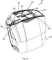
Fig. 1A is a top perspective view of a dispenser according to an embodiment of this disclosure, with a water treatment cartridge received in the cartridge receiving chamber and the actuation member being at its locked position. -
Fig. 1B shows the dispenser ofFig. 1A , however with the actuation member being at its unlocked position. -
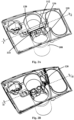
Fig. 2A is a top perspective view of the cartridge receiving chamber of the dispenser ofFig. 1A , shown in isolation with the cartridge removed for ease of viewing. -
Fig. 2B is a top perspective view of the cartridge receiving chamber of the dispenser ofFig. 1B , shown in isolation with the cartridge removed for ease of viewing. -
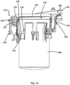
Fig. 3A is a longitudinal cross section of the cartridge receiving chamber through line I-I inFig. 2A . -
Fig. 3B is a longitudinal cross section of the cartridge receiving chamber through line II-II inFig. 2B . - Shown in
Figs. 1A-1B , is a beverage dispenser according to an exemplary embodiment of this disclosure.Beverage dispenser 100 is configured to receive source water from a source viainlet 102, feed the source water intowater treatment cartridge 104, and dispense treated water-based beverage (e.g. water, carbonated water, flavored water, hot water, cold water, etc.) viadispenser outlet 106. The dispenser may include additional disinfection utilities, such as aUV lamp 105, to further treat the source water. In this specific embodiment,water treatment cartridge 104 is received withincartridge receiving chamber 108 via atop opening 110 of the chamber, permitting insertion and extraction of the cartridge from the chamber as will be explained below. - As can better be seen in
Figs. 2A-3B , thecartridge receiving chamber 108 has asource water inlet 112 and a treatedwater outlet 114, configured to receive and form fluid communication with cartridge water inlet and treated water cartridge outlet (both not shown) of a cartridge when received in the chamber and in the cartridge operative position, as will be discussed below. Thecartridge chamber 108 is fitted with acartridge seat 116 constituted by L-shapedmember 117, that is configured with acartridge engaging member 118. Thecartridge engaging member 118 fits into and engages with a seat-receiving location formed at an external wall portion of the cartridge (not shown) when received within the cartridge receiving chamber, thus coupling between the cartridge seat and the cartridge. - An actuation member in the form of
lever 120, is associated with thecartridge seat 116 via a movement translation mechanism, generally designated 122. The movement translation mechanism includes acogwheel 124, linked to lever 120 via a linkingbridge 126. Thus, angular movement of the lever from its locked position (shown inFigs. 1A ,2A ,3A ) to its unlocked position (shown inFigs. 1B ,2B ,3B ) causes rotation of thecogwheel 124.Cogwheel 124 is held between two toothed racks, afirst rack 128 being formed on a portion of verticallydisplaceable member 129, and asecond rack 130 that is formed on a surface of the L-shapedmember 117 forming thecartridge seat 116. Hence, angular displacement oflever 120 in the direction ofarrow 132 from the locked position (Fig. 3A ) to the unlocked position (Fig. 3B ), causes rotation of cogwheel 124 - as the cogwheel is held betweenracks member 129 in the direction ofarrow 134, and upward vertical displacement of L-shapedmember 117 along the direction ofarrow 136. The upward displacement of L-shapedmember 117 causes the cartridge seat 116 (and the cartridge held thereby) to displace from its cartridge operative position (Fig. 3A ) to its cartridge extraction position (Fig. 3B ). - As can be seen in
Fig. 1A , when the lever is in its locked position, the cartridge seat is at its cartridge operative position, such that atop surface 140 of thecartridge 104 is flush with arim 142 of thechamber 108. When the lever is moved to its unlocked position (Fig. 1B ), the cartridge seat is displaced upwardly into the cartridge extraction position, causing thetop surface 140 to protrude from the chamber beyondrim 142, thus enabling user access to the cartridge for its removal from the chamber. -
Lever 120 extends acrosstop opening 110 ofchamber 108 when the lever is in its locked position, thus both holding the cartridge in its operative position and preventing undesired extraction of the cartridge from the chamber during its operation. For holding thelever 120 in its locked position, the lever is provided with a lockinglatch 144, configured onto a flexible orsemi-flexible arm 146 of the lever's user-accessible handle 148. The locking latch is configured to be releasably received within a latch-receiving location, in this example withinslot 150, formed in thehousing 151 ofdispenser 100. Due to its partial flexibility, pressing thearm 146 towards the direction ofarrow 152 will cause the lockinglatch 144 to disengage from theslot 150, thereby unlocking the lever and permitting its displacement from the locked position to the unlocked position. - It is noted that the movement translation mechanism (or any of its parts) and/or the latch receiving location can be associated with sensors, e.g. microswitches, allowing a controlling unit of the dispenser to receive indication of the position of the lever and/or the cartridge seat. Flow sensors can also be provided at one or both of the source water inlet and the treated water outlet of the chamber in order to provide indication whether the cartridge is in operation or disengaged from the water inlet and outlet of the chamber.
Claims (10)
- A cartridge extraction unit configured for fitting into a cartridge receiving chamber (108) of a beverage dispenser (100) the cartridge extraction unit comprising:a cartridge seat (116) configured to slidingly displace within the cartridge receiving chamber (108) between a cartridge operative position in which a water inlet of the cartridge and the treated water outlet of the cartridge establish a fluid communication with a water inlet (112) and a treated water outlet (114) of said chamber (108), respectively, and a cartridge extraction position in which the cartridge water inlet and the treated water cartridge outlet are disengaged from the water inlet and the treated water outlet of the chamber, respectively, the cartridge seat configured to engage a seat-receiving location formed at an external wall portion of said cartridge when received within the cartridge receiving chamber; anda user-accessible actuation member associated with the cartridge seat and switchable between a locked position and an unlocked position, the actuation member being configured to slidingly displace the cartridge seat between said cartridge operative position, corresponding to said locked position, and said cartridge extraction position that corresponds to said unlocked position,wherein said user-accessible actuation member is a lever (120) associated with the cartridge seat (116) via a movement translation mechanism (122), the movement transition mechanism (122) comprises a cogwheel (124), rotationally held between a first, vertically displaceable toothed rack (128) associated or being part of the lever (120), and a second, toothed rack (130) that is formed on a surface of the cartridge seat (116), whereby displacement of the lever (120) between the locked position and the unlocked position causes downward vertical displacement of the first rack (128) to rotate the cogwheel (124), thereby causing upward vertical displacement of the second rack (130) to axially slidingly displace the cartridge seat (116) between the cartridge operative position and the cartridge extraction position.
- A beverage dispenser (100) comprising: a housing having a cartridge receiving chamber (108), the chamber (108) comprising a water inlet (112) and a treated water outlet (114) configured to connect to a cartridge water inlet and a treated water cartridge outlet of a water treatment cartridge (104), a cartridge extraction unit according to claim 1.
- The beverage dispenser of claim 2, wherein the cartridge extraction position is vertically displaced from the cartridge operative position along a longitudinal axis of the cartridge receiving chamber.
- The beverage dispenser of claim 3, wherein the cartridge receiving chamber comprises a top opening (110) configured to permit insertion and extraction of the cartridge from the cartridge receiving chamber.
- The beverage dispenser of claim 4, wherein, when the cartridge is received with the cartridge chamber and the cartridge seat is at its cartridge operative position, a top external surface of the cartridge is flush with or below a rim (142) of the cartridge receiving chamber, and when the cartridge seat is at its cartridge extraction position, the top surface of the cartridge chamber protrudes above said rim.
- The beverage dispenser of any one of claims 2 to 5, wherein in the locked position, the lever extends across a cartridge insertion opening (110) of the cartridge receiving chamber.
- The beverage dispenser of claim 6, wherein in the unlocked position, the lever is angled with respect to a plane defined by the cartridge insertion opening.
- The beverage dispenser of any one of claims 2 to 7, wherein the lever comprises a locking latch (144) configured, when the lever is in its locked position, to be releasably received within a latch-receiving location (150) formed at a rim (142) of the cartridge receiving chamber.
- The beverage dispenser of any one of claims 2 to 7, wherein the lever comprises a locking latch configured, when the lever is in its locked position, to be releasably received within a latch-receiving location formed at the housing.
- The beverage dispenser of claim 8 or 9, wherein the lever comprises a user-accessible handle (148) configured for disengaging the locking latch from the latch-receiving location.
Applications Claiming Priority (2)
| Application Number | Priority Date | Filing Date | Title |
|---|---|---|---|
| IL275788A IL275788B2 (en) | 2020-07-01 | 2020-07-01 | Cartridge extraction mechanism |
| PCT/IL2021/050814 WO2022003697A1 (en) | 2020-07-01 | 2021-07-01 | Cartridge extraction unit for water purifier |
Publications (3)
| Publication Number | Publication Date |
|---|---|
| EP4175913A1 EP4175913A1 (en) | 2023-05-10 |
| EP4175913C0 EP4175913C0 (en) | 2024-06-19 |
| EP4175913B1 true EP4175913B1 (en) | 2024-06-19 |
Family
ID=79010390
Family Applications (1)
| Application Number | Title | Priority Date | Filing Date |
|---|---|---|---|
| EP21740245.2A Active EP4175913B1 (en) | 2020-07-01 | 2021-07-01 | Cartridge extraction unit for water purifier |
Country Status (6)
| Country | Link |
|---|---|
| US (1) | US12616333B2 (en) |
| EP (1) | EP4175913B1 (en) |
| CN (2) | CN216675485U (en) |
| ES (1) | ES2992780T3 (en) |
| IL (1) | IL275788B2 (en) |
| WO (1) | WO2022003697A1 (en) |
Families Citing this family (5)
| Publication number | Priority date | Publication date | Assignee | Title |
|---|---|---|---|---|
| IL275788B2 (en) * | 2020-07-01 | 2024-05-01 | Strauss Water Ltd | Cartridge extraction mechanism |
| USD1064703S1 (en) * | 2023-02-09 | 2025-03-04 | LNJ Group, LLC | Beverage dispenser |
| USD1040591S1 (en) * | 2023-05-25 | 2024-09-03 | A. S. Marketing Systems Ltd | Water dispenser |
| USD1109785S1 (en) * | 2023-10-27 | 2026-01-20 | Swimc Llc | Cover for a dispensing assembly |
| USD1108866S1 (en) * | 2024-01-18 | 2026-01-13 | Strauss Water Ltd | Domestic carbonated drink preparing device |
Citations (1)
| Publication number | Priority date | Publication date | Assignee | Title |
|---|---|---|---|---|
| EP1775538B1 (en) * | 2005-10-12 | 2016-08-10 | Whirlpool Corporation | Water filter for refrigerator water dispenser |
Family Cites Families (9)
| Publication number | Priority date | Publication date | Assignee | Title |
|---|---|---|---|---|
| US5397462A (en) * | 1993-08-24 | 1995-03-14 | Matsushita Electric Industrial Co., Ltd. | Filter with laterally removable element and valve means |
| US6554165B2 (en) * | 2001-03-15 | 2003-04-29 | Cactrus Drink Systems Inc. | Beverage dispenser |
| DE202008012412U1 (en) * | 2008-07-24 | 2009-12-03 | Liebherr-Hausgeräte Ochsenhausen GmbH | Water filter unit |
| IL212134A (en) * | 2011-02-08 | 2012-09-24 | Strauss Water Ltd | Beverage dispenser with a removable filter |
| EP2983568A1 (en) * | 2013-04-11 | 2016-02-17 | Ethical Coffee Company SA | Machine for preparing a drink |
| US9439532B2 (en) * | 2014-03-11 | 2016-09-13 | Starbucks Corporation | Beverage production machines with multi-chambered basket units |
| CN106458558B (en) * | 2014-05-05 | 2019-01-11 | 磨王公司 | Frozen Beverage Dispenser |
| CN204502554U (en) * | 2015-03-12 | 2015-07-29 | 溢泰(南京)环保科技有限公司 | A kind of filter |
| IL275788B2 (en) * | 2020-07-01 | 2024-05-01 | Strauss Water Ltd | Cartridge extraction mechanism |
-
2020
- 2020-07-01 IL IL275788A patent/IL275788B2/en unknown
-
2021
- 2021-07-01 CN CN202121480690.7U patent/CN216675485U/en not_active Withdrawn - After Issue
- 2021-07-01 WO PCT/IL2021/050814 patent/WO2022003697A1/en not_active Ceased
- 2021-07-01 EP EP21740245.2A patent/EP4175913B1/en active Active
- 2021-07-01 US US18/003,950 patent/US12616333B2/en active Active
- 2021-07-01 CN CN202110743401.6A patent/CN113876203B/en active Active
- 2021-07-01 ES ES21740245T patent/ES2992780T3/en active Active
Patent Citations (1)
| Publication number | Priority date | Publication date | Assignee | Title |
|---|---|---|---|---|
| EP1775538B1 (en) * | 2005-10-12 | 2016-08-10 | Whirlpool Corporation | Water filter for refrigerator water dispenser |
Also Published As
| Publication number | Publication date |
|---|---|
| EP4175913C0 (en) | 2024-06-19 |
| IL275788B1 (en) | 2024-01-01 |
| IL275788A (en) | 2022-01-01 |
| WO2022003697A1 (en) | 2022-01-06 |
| CN113876203A (en) | 2022-01-04 |
| IL275788B2 (en) | 2024-05-01 |
| CN113876203B (en) | 2023-09-29 |
| EP4175913A1 (en) | 2023-05-10 |
| CN216675485U (en) | 2022-06-07 |
| US12616333B2 (en) | 2026-05-05 |
| US20230263334A1 (en) | 2023-08-24 |
| ES2992780T3 (en) | 2024-12-18 |
Similar Documents
| Publication | Publication Date | Title |
|---|---|---|
| US12616333B2 (en) | Cartridge extraction unit for water purifier | |
| CN110945289B (en) | Steam cooking appliance | |
| RU2354435C2 (en) | Refrigerator with purified water | |
| EP0650461B1 (en) | Beverage dispenser | |
| EP2903712B1 (en) | Filtration apparatus | |
| US6105809A (en) | Lid mounting structure of vessel | |
| RU2318423C2 (en) | Coffee beverage preparing machine | |
| US20110185762A1 (en) | Lever design version of "push button" filter | |
| EP2678468B1 (en) | Washing machine with selectively extractable filter | |
| US20220047114A1 (en) | Device for Cleaning an Espresso Machine | |
| JP2022501272A (en) | Liquid dispenser that distributes water and flavored beverages | |
| US9955816B2 (en) | Beverage preparation apparatus | |
| ZA200603286B (en) | Alcoholic beverage dispensing appliance with gas connection | |
| CN116324313B (en) | Single-use beverage dispenser for an appliance | |
| CN108137308B (en) | water dispenser with key | |
| KR20180129772A (en) | Beverage tap device | |
| JP5012205B2 (en) | Beverage extractor | |
| CN120882350A (en) | Beverage brewing device | |
| KR101291981B1 (en) | Built-in water purifier | |
| EP4622910B1 (en) | Beverage dispensing unit for a machine for preparing and dispensing beverages | |
| EP4166049A1 (en) | Coffee machine with beans container module | |
| JPH0228827Y2 (en) | ||
| JPH0515449A (en) | Circulation purification type electric hot water storage container | |
| CA2441019A1 (en) | Valve for liquid dispensing system | |
| HK1249474B (en) | Set of parts for assembling head part for forming a liquid treatment apparatus and method of assembling |
Legal Events
| Date | Code | Title | Description |
|---|---|---|---|
| STAA | Information on the status of an ep patent application or granted ep patent |
Free format text: STATUS: UNKNOWN |
|
| STAA | Information on the status of an ep patent application or granted ep patent |
Free format text: STATUS: THE INTERNATIONAL PUBLICATION HAS BEEN MADE |
|
| PUAI | Public reference made under article 153(3) epc to a published international application that has entered the european phase |
Free format text: ORIGINAL CODE: 0009012 |
|
| STAA | Information on the status of an ep patent application or granted ep patent |
Free format text: STATUS: REQUEST FOR EXAMINATION WAS MADE |
|
| 17P | Request for examination filed |
Effective date: 20230113 |
|
| AK | Designated contracting states |
Kind code of ref document: A1 Designated state(s): AL AT BE BG CH CY CZ DE DK EE ES FI FR GB GR HR HU IE IS IT LI LT LU LV MC MK MT NL NO PL PT RO RS SE SI SK SM TR |
|
| DAV | Request for validation of the european patent (deleted) | ||
| DAX | Request for extension of the european patent (deleted) | ||
| GRAP | Despatch of communication of intention to grant a patent |
Free format text: ORIGINAL CODE: EPIDOSNIGR1 |
|
| STAA | Information on the status of an ep patent application or granted ep patent |
Free format text: STATUS: GRANT OF PATENT IS INTENDED |
|
| INTG | Intention to grant announced |
Effective date: 20240117 |
|
| GRAS | Grant fee paid |
Free format text: ORIGINAL CODE: EPIDOSNIGR3 |
|
| GRAA | (expected) grant |
Free format text: ORIGINAL CODE: 0009210 |
|
| STAA | Information on the status of an ep patent application or granted ep patent |
Free format text: STATUS: THE PATENT HAS BEEN GRANTED |
|
| AK | Designated contracting states |
Kind code of ref document: B1 Designated state(s): AL AT BE BG CH CY CZ DE DK EE ES FI FR GB GR HR HU IE IS IT LI LT LU LV MC MK MT NL NO PL PT RO RS SE SI SK SM TR |
|
| REG | Reference to a national code |
Ref country code: GB Ref legal event code: FG4D |
|
| REG | Reference to a national code |
Ref country code: CH Ref legal event code: EP |
|
| REG | Reference to a national code |
Ref country code: DE Ref legal event code: R096 Ref document number: 602021014612 Country of ref document: DE |
|
| U01 | Request for unitary effect filed |
Effective date: 20240710 |
|
| U07 | Unitary effect registered |
Designated state(s): AT BE BG DE DK EE FI FR IT LT LU LV MT NL PT RO SE SI Effective date: 20240902 |
|
| U20 | Renewal fee for the european patent with unitary effect paid |
Year of fee payment: 4 Effective date: 20240905 |
|
| PG25 | Lapsed in a contracting state [announced via postgrant information from national office to epo] |
Ref country code: HR Free format text: LAPSE BECAUSE OF FAILURE TO SUBMIT A TRANSLATION OF THE DESCRIPTION OR TO PAY THE FEE WITHIN THE PRESCRIBED TIME-LIMIT Effective date: 20240619 |
|
| REG | Reference to a national code |
Ref country code: GR Ref legal event code: EP Ref document number: 20240401966 Country of ref document: GR Effective date: 20241007 |
|
| PG25 | Lapsed in a contracting state [announced via postgrant information from national office to epo] |
Ref country code: HR Free format text: LAPSE BECAUSE OF FAILURE TO SUBMIT A TRANSLATION OF THE DESCRIPTION OR TO PAY THE FEE WITHIN THE PRESCRIBED TIME-LIMIT Effective date: 20240619 Ref country code: RS Free format text: LAPSE BECAUSE OF FAILURE TO SUBMIT A TRANSLATION OF THE DESCRIPTION OR TO PAY THE FEE WITHIN THE PRESCRIBED TIME-LIMIT Effective date: 20240919 |
|
| REG | Reference to a national code |
Ref country code: ES Ref legal event code: FG2A Ref document number: 2992780 Country of ref document: ES Kind code of ref document: T3 Effective date: 20241218 |
|
| PG25 | Lapsed in a contracting state [announced via postgrant information from national office to epo] |
Ref country code: PL Free format text: LAPSE BECAUSE OF FAILURE TO SUBMIT A TRANSLATION OF THE DESCRIPTION OR TO PAY THE FEE WITHIN THE PRESCRIBED TIME-LIMIT Effective date: 20240619 |
|
| PG25 | Lapsed in a contracting state [announced via postgrant information from national office to epo] |
Ref country code: IS Free format text: LAPSE BECAUSE OF FAILURE TO SUBMIT A TRANSLATION OF THE DESCRIPTION OR TO PAY THE FEE WITHIN THE PRESCRIBED TIME-LIMIT Effective date: 20241019 |
|
| PG25 | Lapsed in a contracting state [announced via postgrant information from national office to epo] |
Ref country code: CZ Free format text: LAPSE BECAUSE OF FAILURE TO SUBMIT A TRANSLATION OF THE DESCRIPTION OR TO PAY THE FEE WITHIN THE PRESCRIBED TIME-LIMIT Effective date: 20240619 |
|
| PG25 | Lapsed in a contracting state [announced via postgrant information from national office to epo] |
Ref country code: SK Free format text: LAPSE BECAUSE OF FAILURE TO SUBMIT A TRANSLATION OF THE DESCRIPTION OR TO PAY THE FEE WITHIN THE PRESCRIBED TIME-LIMIT Effective date: 20240619 |
|
| PG25 | Lapsed in a contracting state [announced via postgrant information from national office to epo] |
Ref country code: SM Free format text: LAPSE BECAUSE OF FAILURE TO SUBMIT A TRANSLATION OF THE DESCRIPTION OR TO PAY THE FEE WITHIN THE PRESCRIBED TIME-LIMIT Effective date: 20240619 |
|
| PG25 | Lapsed in a contracting state [announced via postgrant information from national office to epo] |
Ref country code: SM Free format text: LAPSE BECAUSE OF FAILURE TO SUBMIT A TRANSLATION OF THE DESCRIPTION OR TO PAY THE FEE WITHIN THE PRESCRIBED TIME-LIMIT Effective date: 20240619 Ref country code: SK Free format text: LAPSE BECAUSE OF FAILURE TO SUBMIT A TRANSLATION OF THE DESCRIPTION OR TO PAY THE FEE WITHIN THE PRESCRIBED TIME-LIMIT Effective date: 20240619 Ref country code: PL Free format text: LAPSE BECAUSE OF FAILURE TO SUBMIT A TRANSLATION OF THE DESCRIPTION OR TO PAY THE FEE WITHIN THE PRESCRIBED TIME-LIMIT Effective date: 20240619 Ref country code: IS Free format text: LAPSE BECAUSE OF FAILURE TO SUBMIT A TRANSLATION OF THE DESCRIPTION OR TO PAY THE FEE WITHIN THE PRESCRIBED TIME-LIMIT Effective date: 20241019 Ref country code: CZ Free format text: LAPSE BECAUSE OF FAILURE TO SUBMIT A TRANSLATION OF THE DESCRIPTION OR TO PAY THE FEE WITHIN THE PRESCRIBED TIME-LIMIT Effective date: 20240619 |
|
| REG | Reference to a national code |
Ref country code: CH Ref legal event code: PL |
|
| PG25 | Lapsed in a contracting state [announced via postgrant information from national office to epo] |
Ref country code: MC Free format text: LAPSE BECAUSE OF FAILURE TO SUBMIT A TRANSLATION OF THE DESCRIPTION OR TO PAY THE FEE WITHIN THE PRESCRIBED TIME-LIMIT Effective date: 20240619 |
|
| PG25 | Lapsed in a contracting state [announced via postgrant information from national office to epo] |
Ref country code: MC Free format text: LAPSE BECAUSE OF FAILURE TO SUBMIT A TRANSLATION OF THE DESCRIPTION OR TO PAY THE FEE WITHIN THE PRESCRIBED TIME-LIMIT Effective date: 20240619 |
|
| PG25 | Lapsed in a contracting state [announced via postgrant information from national office to epo] |
Ref country code: CH Free format text: LAPSE BECAUSE OF NON-PAYMENT OF DUE FEES Effective date: 20240731 |
|
| PLBE | No opposition filed within time limit |
Free format text: ORIGINAL CODE: 0009261 |
|
| STAA | Information on the status of an ep patent application or granted ep patent |
Free format text: STATUS: NO OPPOSITION FILED WITHIN TIME LIMIT |
|
| 26N | No opposition filed |
Effective date: 20250320 |
|
| PGFP | Annual fee paid to national office [announced via postgrant information from national office to epo] |
Ref country code: GB Payment date: 20250605 Year of fee payment: 5 |
|
| PGFP | Annual fee paid to national office [announced via postgrant information from national office to epo] |
Ref country code: GR Payment date: 20250618 Year of fee payment: 5 |
|
| PG25 | Lapsed in a contracting state [announced via postgrant information from national office to epo] |
Ref country code: IE Free format text: LAPSE BECAUSE OF NON-PAYMENT OF DUE FEES Effective date: 20240701 |
|
| U20 | Renewal fee for the european patent with unitary effect paid |
Year of fee payment: 5 Effective date: 20250621 |
|
| PGFP | Annual fee paid to national office [announced via postgrant information from national office to epo] |
Ref country code: ES Payment date: 20250805 Year of fee payment: 5 |
|
| PGFP | Annual fee paid to national office [announced via postgrant information from national office to epo] |
Ref country code: NO Payment date: 20250709 Year of fee payment: 5 |
|
| PG25 | Lapsed in a contracting state [announced via postgrant information from national office to epo] |
Ref country code: CY Free format text: LAPSE BECAUSE OF FAILURE TO SUBMIT A TRANSLATION OF THE DESCRIPTION OR TO PAY THE FEE WITHIN THE PRESCRIBED TIME-LIMIT; INVALID AB INITIO Effective date: 20210701 |
|
| PG25 | Lapsed in a contracting state [announced via postgrant information from national office to epo] |
Ref country code: HU Free format text: LAPSE BECAUSE OF FAILURE TO SUBMIT A TRANSLATION OF THE DESCRIPTION OR TO PAY THE FEE WITHIN THE PRESCRIBED TIME-LIMIT; INVALID AB INITIO Effective date: 20210701 |
|
| U1N | Appointed representative for the unitary patent procedure changed after the registration of the unitary effect |
Representative=s name: MARKS & CLERK LLP; GB |