EP4175601B1 - Patient handling apparatus - Google Patents
Patient handling apparatus Download PDFInfo
- Publication number
- EP4175601B1 EP4175601B1 EP21733965.4A EP21733965A EP4175601B1 EP 4175601 B1 EP4175601 B1 EP 4175601B1 EP 21733965 A EP21733965 A EP 21733965A EP 4175601 B1 EP4175601 B1 EP 4175601B1
- Authority
- EP
- European Patent Office
- Prior art keywords
- patient
- guiding element
- support device
- frame
- handling apparatus
- Prior art date
- Legal status (The legal status is an assumption and is not a legal conclusion. Google has not performed a legal analysis and makes no representation as to the accuracy of the status listed.)
- Active
Links
Images


Classifications
-
- A—HUMAN NECESSITIES
- A61—MEDICAL OR VETERINARY SCIENCE; HYGIENE
- A61G—TRANSPORT, PERSONAL CONVEYANCES, OR ACCOMMODATION SPECIALLY ADAPTED FOR PATIENTS OR DISABLED PERSONS; OPERATING TABLES OR CHAIRS; CHAIRS FOR DENTISTRY; FUNERAL DEVICES
- A61G7/00—Beds specially adapted for nursing; Devices for lifting patients or disabled persons
- A61G7/10—Devices for lifting patients or disabled persons, e.g. special adaptations of hoists thereto
- A61G7/1001—Devices for lifting patients or disabled persons, e.g. special adaptations of hoists thereto specially adapted for specific applications
- A61G7/1003—Devices for lifting patients or disabled persons, e.g. special adaptations of hoists thereto specially adapted for specific applications mounted on or in combination with a bath-tub
-
- A—HUMAN NECESSITIES
- A61—MEDICAL OR VETERINARY SCIENCE; HYGIENE
- A61G—TRANSPORT, PERSONAL CONVEYANCES, OR ACCOMMODATION SPECIALLY ADAPTED FOR PATIENTS OR DISABLED PERSONS; OPERATING TABLES OR CHAIRS; CHAIRS FOR DENTISTRY; FUNERAL DEVICES
- A61G7/00—Beds specially adapted for nursing; Devices for lifting patients or disabled persons
- A61G7/10—Devices for lifting patients or disabled persons, e.g. special adaptations of hoists thereto
- A61G7/1013—Lifting of patients by
- A61G7/1019—Vertical extending columns or mechanisms
-
- A—HUMAN NECESSITIES
- A61—MEDICAL OR VETERINARY SCIENCE; HYGIENE
- A61G—TRANSPORT, PERSONAL CONVEYANCES, OR ACCOMMODATION SPECIALLY ADAPTED FOR PATIENTS OR DISABLED PERSONS; OPERATING TABLES OR CHAIRS; CHAIRS FOR DENTISTRY; FUNERAL DEVICES
- A61G7/00—Beds specially adapted for nursing; Devices for lifting patients or disabled persons
- A61G7/10—Devices for lifting patients or disabled persons, e.g. special adaptations of hoists thereto
- A61G7/104—Devices carried or supported by
- A61G7/1046—Mobile bases, e.g. having wheels
-
- A—HUMAN NECESSITIES
- A61—MEDICAL OR VETERINARY SCIENCE; HYGIENE
- A61G—TRANSPORT, PERSONAL CONVEYANCES, OR ACCOMMODATION SPECIALLY ADAPTED FOR PATIENTS OR DISABLED PERSONS; OPERATING TABLES OR CHAIRS; CHAIRS FOR DENTISTRY; FUNERAL DEVICES
- A61G7/00—Beds specially adapted for nursing; Devices for lifting patients or disabled persons
- A61G7/10—Devices for lifting patients or disabled persons, e.g. special adaptations of hoists thereto
- A61G7/1049—Attachment, suspending or supporting means for patients
- A61G7/1059—Seats
Definitions
- the present invention relates to a patient handling apparatus.
- Patient handling apparatuses such as lifts, also referred to as patient hoists, are commonly used to raise, lower and transfer patients who are disabled or who otherwise have mobility problems.
- Two common types of patient lifts are stanchion-mounted lifts, also known as floor lifts. and ceiling lifts.
- Floor lifts often have a hoist assembly which may be disposed at the upper end of a stanchion or a chair movably mounted to the stanchion.
- the stanchion has a wheeled base, which allows for the lift to be moved along the ground to different locations.
- One common application for a patient handling apparatuses is to transfer patients into and out of a bathtub. This is associated with a number of challenges.
- the patient has to be seated securely without the risk of falling out, this is particularly important in cases where the patient has a limited balance when seated. Further, the patient has to be lifted high enough over the tub of the rim in order to clear the tub with the patient's feet.
- it is crucial to avoid a feeling of free falling for the patient.
- the feeling of free falling is particularly strong when only the backrest of the patient handling backrest is folded and the seat remains horizontal.
- the patient handling apparatus for such an application implements a bath chair, i.e. a chair mounted to the frame or chassis of the patient handling apparatus.
- the bath chair only allows vertical movements with a fix hip angle, i.e. angle between a back portion and seat portion of the bath chair.
- the patient handling apparatus provides a tilting movement once the chair comes in contact with sloping surfaces of the bath.
- Bath stretchers are more suitable for patients requiring more support and are less mobile.
- Some bath stretches enable a combination of independent height adjustment of the stretcher and a tiltable back rest.
- Such bath stretches typically implement technology which enables the back rest to be lifted or lowered, either manually or electrically. However, since only the angle of the back rest is reclinable the comfort is lacking.
- a patient handling apparatus comprises a base with a frame and a patient support device.
- the patient support device is movable relative to the base.
- the patient support device is movably mounted to the frame between an upright and an inclined position. In the inclined position, the patient support device is inclined backwards or forwards in the inclined position relative to the upright position by means of a guiding arrangement.
- the guiding arrangement comprises at least one frame guiding element mounted to the frame.
- the guiding arrangement further comprises a support guiding element mounted to the patient support device.
- the support guiding element is movably connected to the frame guiding element and at least one of the at least one frame guiding element and the support guiding element has a continuously arched portion concave relative the patient support device in the upright position.
- the continuously arched portion is arranged to guide a relative movement between the support guiding element and the frame guiding element for providing movement of the patient support device between the upright and inclined position.
- FIG. 1 shows a patient handling apparatus 10.
- the patient handling apparatus 10 comprises a base 30 with a frame 31.
- the base 30 may be movable relative the ground.
- the base 30 may be provided with wheels 32, 33 adapted to allow movement of the base, i.e. the patient handling apparatus 10, relative the ground.
- the base 30 may comprise a horizontal portion 39.
- the frame 31 may extend orthogonally to the horizontal portion.
- the horizontal portion 39 may be provided with the wheels 32, 33.
- the frame 31 may protrude from a position adjacent to an end of the horizontal portion 39. Said frame 31 may further be substantially aligned with one or more of the wheels 33.
- the patient handling apparatus 10 comprises a patient support device 20.
- the patient support device 20 is adapted to support a patient, i.e. support the weight of said patient.
- the patient support device 20 is movable relative to the base 30.
- the patient support device 20 is movably mounted to the frame 31.
- the patient support device 20 is movable between an upright position and an inclined position.
- the patient support device 20 is inclined backwards or forwards in the inclined position relative to the upright position by means of a guiding arrangement 70.
- An upright position may herein be defined as a position wherein the patient supported by the patient support device 20 is in an upright position. Accordingly, the spine of the patient extends substantially in a vertical direction when supported by the patient support device 20 in the upright position.
- An inclined position may herein be defined as a position wherein the patient supported by the patient support device 20 is an inclined position, i.e. an inclined position relative the upright position.
- the inclined position is thus a position wherein the patient is tilted, i.e. the spine of the patient is tilted, relative a vertical axis of the patient handling apparatus.
- the guiding arrangement 70 comprises at least one frame guiding element 72, 84.
- the at least one frame guiding element 72, 84 is mounted to the frame 31.
- the guiding arrangement 70 further comprises a support guiding element 71.
- the support guiding element 71 is mounted to the patient support device 20.
- the support guiding element 71 is movably connected to the frame guiding element 72, 84. At least one of the at least one frame guiding element 72, 84 and the support guiding element 71 has a continuously arched portion.
- the continuously arched portion is concave relative the patient support device 20 in the upright position. Accordingly, the continuously arched portion is concave relative patient support device 20 when the patient support device 20 is in the upright position.
- the continuously arched portion is arranged to guide a relative movement between the support guiding element 71 and the frame guiding element 72, 84 for providing movement of the patient support device 20 between the upright and inclined position.
- the patient support device 20 may be movable backwards or forwards to the inclined position relative the upright position about a horizontal axis.
- the horizontal axis may extend through a vertical plane.
- the horizontal axis may be extending orthogonally to the vertical plane.
- the continuously arched portion may extend in said vertical plane.
- the continuously arched portion may be arranged to guide the relative movement between the support guiding element 71 and the frame guiding element 72, 84 in said vertical plane for providing the movement of the patient support device 20 between the upright and inclined position.
- This type of guiding arrangement is associated with a number of advantages. Firstly, it allows for the patient support device to maintain an orientation which provides a natural position for the patient both when the patient support device is in the inclined position and the upright position. Secondly, the tilting movement of the patient support device may be achieved without the need of a support structure underneath the patient support device since the load of the patient support device and patient as well as the guiding arrangement may be concentrated to a vertical frame. This is particularly advantageous in the field of bath chairs and lifts wherein it is of great importance to be able to raise, lower and pivot a patient inside a bath tub or pool.
- the patient handling apparatus according to the invention allows for all of the required operations without the base obstructing. Also, it makes it possible to adjust the angle of patient support device inside a bath tub which is functionality not provided by conventional patient handling apparatuses.
- the horizontal axis may be defined as a tilt axis of the patient support device 20.
- the horizontal axis may be arranged to extend through a centrum point of a circular sector formed by the continuously arched portion. Said circular sector may extend in the previously mentioned vertical plane.
- the patient support device 20 is mounted to the base 30 solely by means of the guiding arrangement 70.
- the patient support device 20 is only suspended from the base 30 at the guiding arrangement 70.
- the space underneath the patient support device may be kept free from structural elements for supporting the patient support device.
- a connecting point P formed by the connection between the patient support device 20 and the support guiding element 71 may be movable along a curved trajectory about the horizontal axis.
- the curved trajectory may be a continuation of the continuously arched portion, i.e. the circular sector.
- the patient support device 20 is mounted to the base 30 solely at the connection point P.
- Movement of the patient support device backwards from the upright position to the inclined position may be considered a movement along said curved trajectory, i.e. along the frame guiding element 72, 84, towards the base 30.
- the connecting point P is moved towards the frame guiding element 72, 84 along the curved trajectory.
- Movement of the patient support device forwards from the upright position to the inclined position may be considered a movement along said curved trajectory, i.e. along the frame guiding element 72, 84, away from the base 30.
- the connecting point P is moved away from the frame guiding element 72, 84 along the curved trajectory.
- the patient support device 20 may be movable up to 45 degrees backwards or forwards to the inclined position relative the upright position about a horizontal axis.
- the patient support device 20 may be movable up to 30 degrees backwards or forwards to the inclined position relative the upright position about the horizontal axis.
- the patient support device 20 is movably mounted to the frame 31 between an upright and an inclined position in which the patient support device 20 is inclined backwards relative to the upright position. This allows for the patient to maintain a comfortable position and a sense of safety.
- the patient support device 20 may comprise a seat supporting section 21.
- the seat supporting section 21 is adapted to support the rear of a patient.
- the patient support device 20 may further comprise a back supporting section 22.
- the back supporting section 22 is adapted to support the back of a patient.
- the tilting of the patient support device 20 between the upright position and the inclined position allows for the sitting position of the patient to be maintained in a natural manner during movement of the patient support device.
- the patient support device 20 may be in the form of a chair support.
- the patient support device 20 is thus adapted to support a seated patient.
- the back supporting section 22 and the seat supporting section 21 may be substantially orthogonal to each other.
- the patient support device 20 may further comprise a calf supporting section pivotally mounted to the seat supporting section 21. Said calf supporting section is adapted to support the calves of a patient supported by the patient support device 20.
- the patient support device 20 may be a stretcher.
- the patient support device 20 may comprise a substantially planar member. Said substantially planar member is adapted to support a patient, i.e. a patient in a recumbent position.
- the patient support device 20 has the back supporting section 22 and the seat supporting section 21.
- the support guiding element 71 is mounted to the back supporting section 22 of the patient support device 20.
- the support guiding element 71 may be mounted to a top portion 23 of the back supporting section 22.
- the top portion 23 is the uppermost portion of the back supporting section 23 when the patient support device 20 is in the upright position.
- top portion 23 fix to the support guiding element 71 ensures that all structural elements of the patient handling apparatus may be kept outside a bath tub during lifting and handling operations. This is achieved while the arched portion provides the desired pivoting movement of the patient support device 20.
- the connecting point P may thus be arranged between the back supporting section 22 and the support guiding element 71.
- the connecting point P may further be arranged between the top portion 23 and the support guiding element 71.
- the top portion 23 may be further adapted to support the back of the head of a patient. Accordingly, said top portion 23 may constitute a neck support portion.
- the patient support device 20 is a substantially rigid patient support device.
- the patient support device 20 may be in a rigid material, such as plastic.
- the patient support device 20 may be in the form of a rigid chair.
- the rigid patient support device may be provided with padded sections for additional support.
- the substantially rigid patient support device 20 allows for a more stable movement of the patient by means of the patient handling apparatus compared to a flexible patient support device such as for example a patient sling.
- the patient handling apparatus may be arranged such that the center of gravity of the patient supported by the patient support device is arranged with a horizontal offset relative the load bearing structure of the patient handling apparatus, i.e. the frame 31. Accordingly, the patient handling apparatus may be arranged such that the center of gravity of the patient supported by the patient support device is arranged at a horizontal distance from the load bearing structure of the patient handling apparatus, i.e. the frame 31.
- the moving of the patient at said offset increases the stability of the movement and allows for unobstructed lifting over obstacles such as beds. This may be achieved in a number of ways.
- the frame guiding element 72, 84 is arranged at a horizontal distance from the patient support device 20 at least when the patient support device 20 is in the upright position.
- the seat supporting section 21 is arranged at a horizontal distance from the guiding arrangement 70.
- the connection point P is arranged at a horizontal distance from the seat supporting section 21.
- the patient handling apparatus may further implement an arrangement for linear movement, i.e. raising and lowering of the patient support device 20.
- the patient handling apparatus 10 may comprise a translational arrangement 60.
- the translational arrangement 60 movably connects the patient support device 20 and the base 30.
- the translational arrangement 60 is adapted to guide raising and/or lowering of the patient support device 20 relative the base 30 in a vertical direction.
- the translational arrangement 60 and the guiding arrangement 70 are adapted to independently guide the movement of the patient support device 20 relative the frame 30. Hence, the position and/or orientation of the patient support device 20 may be adjusted by means of the translational arrangement 60 and the guiding arrangement 70. The adjustment of the patient support device 20 by means of the translational arrangement 60 is thus independent from the adjustment of said patient support device 20 by means of the guiding arrangement 70.
- the translational arrangement 60 may be a telescopic arrangement.
- the translational arrangement 60 may comprise a support translational member 61 mounted to the patient support device 20 and a guiding translational member 62 mounted to the base 30.
- the support translational member 61 and the guiding translational member 62 are movably connected to allow relative vertical movement between said support translational member 61 and the guiding translational member 62.
- the guiding translational member may be comprised in the frame 31.
- One of the support translational member 61 and the guiding translational member 62 may be hollow and adapted to receive the other of the support translational member 61 and the guiding translational member 62.
- the support translational member 61 may be a hollow member and adapted to receive the guiding translational member 62.
- the guiding translational member 62 is arranged inside the support translational member 61.
- the support translational member 61 is thus movable relative the guiding translational member 62, said guiding translational member 62 being fix. Thereby, a more compact translational arrangement is achieved. Further, having the fix translational member arranged inside the movable translational member mitigates the risk for pinching.
- the patient handling apparatus 10 may further comprise a locking unit.
- the locking unit may be adapted to upon actuation prevent the relative movement between the support guiding element and the at least one frame guiding element.
- the locking unit may thus be adapted to upon actuation prevent relative movement between the patient support device 20 and the base 30 by means of the guiding arrangement 70 and/or the translational arrangement 60.
- the locking unit may be a friction lock such as a brake or a locking pin or any other mean known to the skilled person.
- the guiding arrangement 70 is in the form a gear rack interfacing with a pinion, i.e. a cogged wheel.
- one of the at least one frame guiding element 72 comprises a curved gear rack 79.
- the support guiding element 71 comprises a pinion 41 interfacing with said curved gear rack 79 (depicted in further detail in Figure 3 ).
- the curved gear rack allows for the rotation of the patient support device around the center of mass of the patient. Thus, the patient support device may be moved between the upright and inclined position by a relatively small force.
- the curved gear rack 79 may form the continuously arched portion.
- the curved gear rack 79 may form said continuously arched portion in itself or in conjunction with additional guiding elements.
- a toothed surface of the curved gear rack 79 interfacing with the pinion 41 faces the patient support device 20. This ensures that the engagement between the pinion and the gear rack is preserved, since movement of the patient handling apparatus will cause a contact force onto the pinion towards the gear rack.
- the support guiding element 71 may comprise the continuously arched portion comprising the curved gear rack 79, whereby the frame guiding element 72 may comprise the pinion 41.
- the patient handling apparatus may further comprise a casing 91.
- the casing 91 is mounted to the at least one frame guiding element 72, 84 or the support guiding element 71.
- the casing 91 may be arranged to cover at least a portion of the other of the at least one frame guiding element 71 and the support guiding element 71 at least when the patient support device 20 is in the inclined position.
- the casing reduces the exposure of the moving parts of the patient handling apparatus, thus a safer patient handling apparatus is achieved.
- the casing 91 is arranged to cover the other of the at least one frame guiding element 72, 84 and the support guiding element 71 when the patient support device 20 is an inclined position which is backwards or forwards relative the upright position. Accordingly, the patient support device 20 may be adapted to support a patient facing away from the guiding arrangement or faces the guiding arrangement.
- the casing 91 may act as a part of the guiding arrangement 70 for further securing a robust and stable relative movement of the parts of the guiding arrangement.
- the casing 91 may form the continuously arched portion.
- the casing 91 may form said continuously arched portion in itself or in conjunction with guiding elements such as the previously described curved gear rack.
- the support guiding element 71 may comprise the casing 91.
- One of the at least one frame guiding elements 84 may be arranged to be in contact with the casing 91 for guiding the relative movement between the support guiding element 71 and the frame guiding element 84. This will be further described with reference to Figure 3 .
- At least one frame guiding element may have a matching continuously arched portion in the form of an outer surface corresponding to the casing for guiding relative movement between the casing 91, i.e. the frame guiding element 84, and the support guiding element 71 by means of sliding contact between said casing and continuously arched portion.
- a single frame guiding element 72, 84 may comprise said outer surface and the previously described curved gear rack. Accordingly, the single frame guiding element 72, 84 may comprise a first continuously arched portion comprising the outer surface and a second continuously arched position comprising the curved gear rack.
- a first frame guiding element 84 may comprise said outer surface and a second frame guiding element 72 may comprise the curved gear rack. Accordingly, both the first and second frame guiding element may comprise a continuously arched portion.
- the patient handling apparatus 10 further comprises a drive unit 42 adapted to drive the support guiding element 71 relative the at least one frame guiding element 72.
- the patient support device 20 may be moved relative the base 30 both by means of manual operation and by means of the drive unit 42.
- the patient handling apparatus 10 may be solely manually operated and may thus not comprise said drive unit.
- the at least one of the frame guiding element 72, 84 may have a first end 77 and a second end 78.
- the second end 78 may be opposite to the first end 77.
- the first end 77 may be a non-fixated end and the second end 78 may be mounted to the base 30 and more preferably the frame 31 of the base 30. Having the first end as a free end, i.e. floating end, allows better alignment between the parts of the guiding arrangement since the frame guiding element 72, 84 may flex slightly to guide the relative movement between the parts of the guiding arrangement.
- the first end 77 is a top end of the at least one of frame guiding element 72, 84.
- the second end 78 is a bottom end of the at least one frame guiding element 72, 84.
- the frame guiding element 72, 84 may thus extend in a vertical direction.
- the at least one frame guiding element 72 may comprise the continuously arched portion. Further, the at least one frame guiding element 72 may comprise the curved gear rack 79. Extending along a portion of or the entire length of the frame guiding element 72.
- the patient handling apparatus may comprise a control unit and a user interface connected to said control unit.
- the control unit is connected to the drive unit 42 and configured to control said drive unit 42.
- the user interface is configured to receive a control signal based on user input, whereby the control unit is configured to control the drive unit based on said control signal.
- the patient handling apparatus 10 may comprise at least one support guide 36, 37 adapted to support the relative movement between the support guiding element 71 and the at least one frame guiding element 72, 84.
- the at least one support guide 36, 37 is a roller. The support guide allows the guiding arrangement to carry higher loads without affecting the relative movement of its parts, since the support guide will effectively take up a portion of the load.
- the at least one support guide 36, 37 may be arranged to unload the casing 91.
- the casing 91 may thus be in contact with said at least one support guide 36, 37.
- the casing 91 may be in rolling contact with the at least one support guide 36, 37.
- the at least one support guide may constitute frame guiding elements.
- the frame 31 may comprise at least one vertical column 58, 59.
- the frame 31 may comprise a first and second vertical column 58, 59 extending orthogonally from the horizontal portion 39.
- the first and second vertical column 58, 59 may extend parallel and at a distance from each other. Both the first and second vertical column 58, 59 may be movably connected to the patient support device 20 via the translational arrangement 60.
- the at least one frame guiding element 72, 84 with the continuously arched portion may extend between the vertical columns 58, 59 of the frame 31.
- Said frame guiding element 72, 84 may be attached to said vertical columns 58, 59 of the frame 31.
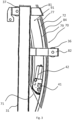
- Figure 3 depicts a partial cross-section of a part of the patient handling apparatus according to an embodiment.
- the patient handling apparatus is depicted when the patient support device is in the inclined position. Accordingly, the support guiding element 71 is in a lowered position relative the frame guiding element 72, 84, whereby the support guiding element 71 is in a raised position relative the frame guiding element 72, 84 when the patient handling apparatus 20 is in the upright position.
- the drive unit 42 may be fix to one of the support guiding element 71 and the frame guiding element 72, 84.
- the drive unit 42 may comprise an electrical motor and a transmission for transferring torque to a driven member of guiding arrangement 70.
- the driven component of the guiding arrangement is the pinion 41.
- the drive unit 42 connected to said pinion 41 and configured to transfer torque to said pinion 41.
- the drive unit 42 is fix to the support guiding element 71.
- the drive unit 42 may be fix to the casing 91.
- the pinion 41 when the pinion 41 is driven by the drive unit 42 in a first rotational direction, the pinion 41 will climb upwards on the curved gear rack 79 causing movement of the patient support device towards the upright position.
- the pinion 41 When the pinion 41 is driven by the drive unit 42 in a second rotational direction, the pinion will climb downwards on the curved gear rack 79 causing movement of the patient support device backwards towards the inclined position.
- Figure 3 depicts the at least one support guide 36, 37 in further detail.
- a first support guide 36 may be mounted to the frame 31.
- the first support guide 36 may be arranged to guide the casing 91 by being in contact with a first outer surface of the casing 91.
- Said first outer surface of the casing 91 may be distal from the patient support device, i.e. facing away from the patient support device.
- a second support guide 37 may be mounted to the frame 31.
- the second support guide 37 may be arranged to guide the casing 91 by being in contact with a second outer surface of the casing 91.
- Said second outer surface of the casing 91 may be proximal the patient support device, i.e. facing the patient support device.
- Supporting both the first and second outer surface of the casing 91 is particularly advantageous, since it provides for unloading of the guiding arrangement resulting in a more robust and durable patient handling apparatus.
- the first support guide 36 may be mounted to the frame 31 by means of a first frame element 82.
- the first support guide 36 is connected to the first support guide 36.
- the first frame element 82 may comprise a U-shaped portion arranged to extend around the casing 91. This provides additional support for the guiding arrangement in case of impacts etc.
- the second support guide 37 may be mounted to the frame 31 by means of a second frame element 81.
- the second support guide 37 is connected to the second support guide 37.
- the second frame element 81 may comprise a U-shaped portion arranged to extend around the casing 91. This provides additional support for the guiding arrangement in case of impacts etc.
- first frame element 82 and the second frame element 81 may be mounted to the vertical columns 58, 59 of the frame 31. Accordingly, a first portion of the first frame element 82 may be mounted to the first vertical column 58 of the frame 31 and a second portion of the first frame element 82 may be mounted to the second vertical column 59 of the frame 31. Correspondingly, a first portion of the second frame element 81 may be mounted to the first vertical column 58 of the frame 31 and a second portion of the second frame element 81 may be mounted to the second vertical column 59 of the frame 31.
Landscapes
- Health & Medical Sciences (AREA)
- Nursing (AREA)
- Life Sciences & Earth Sciences (AREA)
- Animal Behavior & Ethology (AREA)
- General Health & Medical Sciences (AREA)
- Public Health (AREA)
- Veterinary Medicine (AREA)
- Invalid Beds And Related Equipment (AREA)
- Accommodation For Nursing Or Treatment Tables (AREA)
- External Artificial Organs (AREA)
- Handcart (AREA)
Description
- The present invention relates to a patient handling apparatus.
- Patient handling apparatuses such as lifts, also referred to as patient hoists, are commonly used to raise, lower and transfer patients who are disabled or who otherwise have mobility problems. Two common types of patient lifts are stanchion-mounted lifts, also known as floor lifts. and ceiling lifts. Floor lifts often have a hoist assembly which may be disposed at the upper end of a stanchion or a chair movably mounted to the stanchion. The stanchion has a wheeled base, which allows for the lift to be moved along the ground to different locations.
- One common application for a patient handling apparatuses is to transfer patients into and out of a bathtub. This is associated with a number of challenges. The patient has to be seated securely without the risk of falling out, this is particularly important in cases where the patient has a limited balance when seated. Further, the patient has to be lifted high enough over the tub of the rim in order to clear the tub with the patient's feet. In addition, in cases where the patient is elderly and cognitively impaired, it is crucial to avoid a feeling of free falling for the patient. The feeling of free falling is particularly strong when only the backrest of the patient handling backrest is folded and the seat remains horizontal.
- Typically, the patient handling apparatus for such an application implements a bath chair, i.e. a chair mounted to the frame or chassis of the patient handling apparatus. The bath chair only allows vertical movements with a fix hip angle, i.e. angle between a back portion and seat portion of the bath chair. In some cases, the patient handling apparatus provides a tilting movement once the chair comes in contact with sloping surfaces of the bath.
- When the bath chair has been lowered into the chair, the slope of the tub wall has angled the chair correspondingly. The disadvantage with such a bath chair is that it is not possible to adjust the hip angle outside the tub and independently of the height position of the chair.
- Another option is to provide the patient handling apparatus with a bath stretcher. Bath stretchers are more suitable for patients requiring more support and are less mobile. Some bath stretches enable a combination of independent height adjustment of the stretcher and a tiltable back rest. Such bath stretches typically implement technology which enables the back rest to be lifted or lowered, either manually or electrically. However, since only the angle of the back rest is reclinable the comfort is lacking.
- A number of solutions for adjustment of sitting angles for disabled and specifically for wheelchairs are known in the prior art, for example from
US 6,793,232 ,US6793232 ,US2681455 ,US5790995A ,GB2154201 GB2433925 US2014137323A1 ,US2006220429A1 andWO2004/098479 . There are also many technologies that provides mobile chairs that can be transformed to stretchers and vice versa. Common for both these type of technologies is that they all have a supporting structure underneath the seat of the chair or stretcher. When in use with a bath tube there is no room for such a structure. - In the light of the above, there is a need for a patient handling apparatus which addresses the above mentioned challenges.
- The invention is set out in the appended set of claims.
- According to one aspect a patient handling apparatus is provided. The patient handling apparatus comprises a base with a frame and a patient support device. The patient support device is movable relative to the base.
- The patient support device is movably mounted to the frame between an upright and an inclined position. In the inclined position, the patient support device is inclined backwards or forwards in the inclined position relative to the upright position by means of a guiding arrangement.
- The guiding arrangement comprises at least one frame guiding element mounted to the frame. The guiding arrangement further comprises a support guiding element mounted to the patient support device.
- The support guiding element is movably connected to the frame guiding element and at least one of the at least one frame guiding element and the support guiding element has a continuously arched portion concave relative the patient support device in the upright position. The continuously arched portion is arranged to guide a relative movement between the support guiding element and the frame guiding element for providing movement of the patient support device between the upright and inclined position.
- Further objects and features of the present invention will appear from the following detailed description of embodiments of the invention.
- The invention will be described with reference to the accompanying drawings, in which:
-
Figure 1 is a side view of the patient handling apparatus according to an embodiment. -
Figure 2 is a perspective view of the guiding arrangement and the back supporting section of a patient handling apparatus according to an embodiment. -
Figure 3 is a partial cross-section of the guiding arrangement of a patient handling apparatus according to an embodiment. -
Figure 1 shows apatient handling apparatus 10. Thepatient handling apparatus 10 comprises abase 30 with aframe 31. Thebase 30 may be movable relative the ground. Thebase 30 may be provided withwheels patient handling apparatus 10, relative the ground. - The
base 30 may comprise ahorizontal portion 39. Theframe 31 may extend orthogonally to the horizontal portion. Thehorizontal portion 39 may be provided with thewheels - The
frame 31 may protrude from a position adjacent to an end of thehorizontal portion 39. Saidframe 31 may further be substantially aligned with one or more of thewheels 33. - The patient handling
apparatus 10 comprises apatient support device 20. Thepatient support device 20 is adapted to support a patient, i.e. support the weight of said patient. - The
patient support device 20 is movable relative to thebase 30. Thepatient support device 20 is movably mounted to theframe 31. Thepatient support device 20 is movable between an upright position and an inclined position. Thepatient support device 20 is inclined backwards or forwards in the inclined position relative to the upright position by means of a guidingarrangement 70. - An upright position may herein be defined as a position wherein the patient supported by the
patient support device 20 is in an upright position. Accordingly, the spine of the patient extends substantially in a vertical direction when supported by thepatient support device 20 in the upright position. - An inclined position may herein be defined as a position wherein the patient supported by the
patient support device 20 is an inclined position, i.e. an inclined position relative the upright position. The inclined position is thus a position wherein the patient is tilted, i.e. the spine of the patient is tilted, relative a vertical axis of the patient handling apparatus. - The guiding
arrangement 70 comprises at least oneframe guiding element frame guiding element frame 31. The guidingarrangement 70 further comprises asupport guiding element 71. Thesupport guiding element 71 is mounted to thepatient support device 20. - The
support guiding element 71 is movably connected to theframe guiding element frame guiding element support guiding element 71 has a continuously arched portion. The continuously arched portion is concave relative thepatient support device 20 in the upright position. Accordingly, the continuously arched portion is concave relativepatient support device 20 when thepatient support device 20 is in the upright position. - The continuously arched portion is arranged to guide a relative movement between the
support guiding element 71 and theframe guiding element patient support device 20 between the upright and inclined position. - The
patient support device 20 may be movable backwards or forwards to the inclined position relative the upright position about a horizontal axis. The horizontal axis may extend through a vertical plane. Thus, the horizontal axis may be extending orthogonally to the vertical plane. The continuously arched portion may extend in said vertical plane. The continuously arched portion may be arranged to guide the relative movement between thesupport guiding element 71 and theframe guiding element patient support device 20 between the upright and inclined position. - This type of guiding arrangement is associated with a number of advantages. Firstly, it allows for the patient support device to maintain an orientation which provides a natural position for the patient both when the patient support device is in the inclined position and the upright position. Secondly, the tilting movement of the patient support device may be achieved without the need of a support structure underneath the patient support device since the load of the patient support device and patient as well as the guiding arrangement may be concentrated to a vertical frame. This is particularly advantageous in the field of bath chairs and lifts wherein it is of great importance to be able to raise, lower and pivot a patient inside a bath tub or pool. The patient handling apparatus according to the invention allows for all of the required operations without the base obstructing. Also, it makes it possible to adjust the angle of patient support device inside a bath tub which is functionality not provided by conventional patient handling apparatuses.
- Notably, the horizontal axis may be defined as a tilt axis of the
patient support device 20. The horizontal axis may be arranged to extend through a centrum point of a circular sector formed by the continuously arched portion. Said circular sector may extend in the previously mentioned vertical plane. - Preferably, the
patient support device 20 is mounted to the base 30 solely by means of the guidingarrangement 70. Thus, thepatient support device 20 is only suspended from the base 30 at the guidingarrangement 70. Thereby, the space underneath the patient support device may be kept free from structural elements for supporting the patient support device. - A connecting point P formed by the connection between the
patient support device 20 and thesupport guiding element 71 may be movable along a curved trajectory about the horizontal axis. The curved trajectory may be a continuation of the continuously arched portion, i.e. the circular sector. Preferably, thepatient support device 20 is mounted to the base 30 solely at the connection point P. - Movement of the patient support device backwards from the upright position to the inclined position may be considered a movement along said curved trajectory, i.e. along the
frame guiding element base 30. Thus the connecting point P is moved towards theframe guiding element - Movement of the patient support device forwards from the upright position to the inclined position may be considered a movement along said curved trajectory, i.e. along the
frame guiding element base 30. Thus the connecting point P is moved away from theframe guiding element - The
patient support device 20 may be movable up to 45 degrees backwards or forwards to the inclined position relative the upright position about a horizontal axis. - More preferably, the
patient support device 20 may be movable up to 30 degrees backwards or forwards to the inclined position relative the upright position about the horizontal axis. - It is particularly advantageous that the
patient support device 20 is movably mounted to theframe 31 between an upright and an inclined position in which thepatient support device 20 is inclined backwards relative to the upright position. This allows for the patient to maintain a comfortable position and a sense of safety. - In one embodiment, the
patient support device 20 may comprise aseat supporting section 21. Theseat supporting section 21 is adapted to support the rear of a patient. Thepatient support device 20 may further comprise aback supporting section 22. Theback supporting section 22 is adapted to support the back of a patient. - The tilting of the
patient support device 20 between the upright position and the inclined position allows for the sitting position of the patient to be maintained in a natural manner during movement of the patient support device. - In one embodiment, the
patient support device 20 may be in the form of a chair support. Thepatient support device 20 is thus adapted to support a seated patient. Accordingly, theback supporting section 22 and theseat supporting section 21 may be substantially orthogonal to each other. In one embodiment, thepatient support device 20 may further comprise a calf supporting section pivotally mounted to theseat supporting section 21. Said calf supporting section is adapted to support the calves of a patient supported by thepatient support device 20. - In an alternative embodiment, the
patient support device 20 may be a stretcher. Thus, thepatient support device 20 may comprise a substantially planar member. Said substantially planar member is adapted to support a patient, i.e. a patient in a recumbent position. - Further referencing
Figure 1 , thepatient support device 20 has theback supporting section 22 and theseat supporting section 21. Thesupport guiding element 71 is mounted to theback supporting section 22 of thepatient support device 20. - The
support guiding element 71 may be mounted to atop portion 23 of theback supporting section 22. In one embodiment, thetop portion 23 is the uppermost portion of theback supporting section 23 when thepatient support device 20 is in the upright position. - Having the
top portion 23 fix to thesupport guiding element 71 ensures that all structural elements of the patient handling apparatus may be kept outside a bath tub during lifting and handling operations. This is achieved while the arched portion provides the desired pivoting movement of thepatient support device 20. - The connecting point P may thus be arranged between the back supporting
section 22 and thesupport guiding element 71. The connecting point P may further be arranged between thetop portion 23 and thesupport guiding element 71. - In one embodiment, the
top portion 23 may be further adapted to support the back of the head of a patient. Accordingly, saidtop portion 23 may constitute a neck support portion. - In one embodiment, the
patient support device 20 is a substantially rigid patient support device. Thus, thepatient support device 20 may be in a rigid material, such as plastic. For example, thepatient support device 20 may be in the form of a rigid chair. In one embodiment, the rigid patient support device may be provided with padded sections for additional support. The substantially rigidpatient support device 20 allows for a more stable movement of the patient by means of the patient handling apparatus compared to a flexible patient support device such as for example a patient sling. - The patient handling apparatus may be arranged such that the center of gravity of the patient supported by the patient support device is arranged with a horizontal offset relative the load bearing structure of the patient handling apparatus, i.e. the
frame 31. Accordingly, the patient handling apparatus may be arranged such that the center of gravity of the patient supported by the patient support device is arranged at a horizontal distance from the load bearing structure of the patient handling apparatus, i.e. theframe 31. The moving of the patient at said offset increases the stability of the movement and allows for unobstructed lifting over obstacles such as beds. This may be achieved in a number of ways. In one embodiment, theframe guiding element patient support device 20 at least when thepatient support device 20 is in the upright position. In one embodiment, theseat supporting section 21 is arranged at a horizontal distance from the guidingarrangement 70. In one embodiment, the connection point P is arranged at a horizontal distance from theseat supporting section 21. - Again referencing
Figure 1 , the patient handling apparatus may further implement an arrangement for linear movement, i.e. raising and lowering of thepatient support device 20. Thepatient handling apparatus 10 may comprise atranslational arrangement 60. Thetranslational arrangement 60 movably connects thepatient support device 20 and thebase 30. Thetranslational arrangement 60 is adapted to guide raising and/or lowering of thepatient support device 20 relative the base 30 in a vertical direction. - In one embodiment, the
translational arrangement 60 and the guidingarrangement 70 are adapted to independently guide the movement of thepatient support device 20 relative theframe 30. Hence, the position and/or orientation of thepatient support device 20 may be adjusted by means of thetranslational arrangement 60 and the guidingarrangement 70. The adjustment of thepatient support device 20 by means of thetranslational arrangement 60 is thus independent from the adjustment of saidpatient support device 20 by means of the guidingarrangement 70. - As depicted in
Figure 1 , thetranslational arrangement 60 may be a telescopic arrangement. Thetranslational arrangement 60 may comprise a supporttranslational member 61 mounted to thepatient support device 20 and a guidingtranslational member 62 mounted to thebase 30. The supporttranslational member 61 and the guidingtranslational member 62 are movably connected to allow relative vertical movement between said supporttranslational member 61 and the guidingtranslational member 62. The guiding translational member may be comprised in theframe 31. - One of the support
translational member 61 and the guidingtranslational member 62 may be hollow and adapted to receive the other of the supporttranslational member 61 and the guidingtranslational member 62. In one embodiment, the supporttranslational member 61 may be a hollow member and adapted to receive the guidingtranslational member 62. Thus, the guidingtranslational member 62 is arranged inside the supporttranslational member 61. The supporttranslational member 61 is thus movable relative the guidingtranslational member 62, said guidingtranslational member 62 being fix. Thereby, a more compact translational arrangement is achieved. Further, having the fix translational member arranged inside the movable translational member mitigates the risk for pinching. - In one embodiment, the
patient handling apparatus 10 may further comprise a locking unit. The locking unit may be adapted to upon actuation prevent the relative movement between the support guiding element and the at least one frame guiding element. - The locking unit may thus be adapted to upon actuation prevent relative movement between the
patient support device 20 and the base 30 by means of the guidingarrangement 70 and/or thetranslational arrangement 60. - The locking unit may be a friction lock such as a brake or a locking pin or any other mean known to the skilled person.
- Further referencing
Figure 1 , the guidingarrangement 70 is in the form a gear rack interfacing with a pinion, i.e. a cogged wheel. Accordingly, one of the at least oneframe guiding element 72 comprises acurved gear rack 79. Thesupport guiding element 71 comprises apinion 41 interfacing with said curved gear rack 79 (depicted in further detail inFigure 3 ). The curved gear rack allows for the rotation of the patient support device around the center of mass of the patient. Thus, the patient support device may be moved between the upright and inclined position by a relatively small force. - The
curved gear rack 79 may form the continuously arched portion. Thecurved gear rack 79 may form said continuously arched portion in itself or in conjunction with additional guiding elements. - A toothed surface of the
curved gear rack 79 interfacing with thepinion 41 faces thepatient support device 20. This ensures that the engagement between the pinion and the gear rack is preserved, since movement of the patient handling apparatus will cause a contact force onto the pinion towards the gear rack. - Notably, in an alternative embodiment not encompassed by the wording of the claims, the
support guiding element 71 may comprise the continuously arched portion comprising thecurved gear rack 79, whereby theframe guiding element 72 may comprise thepinion 41. - Again referencing
Figure 1 , the patient handling apparatus may further comprise acasing 91. Thecasing 91 is mounted to the at least oneframe guiding element support guiding element 71. - The
casing 91 may be arranged to cover at least a portion of the other of the at least oneframe guiding element 71 and thesupport guiding element 71 at least when thepatient support device 20 is in the inclined position. The casing reduces the exposure of the moving parts of the patient handling apparatus, thus a safer patient handling apparatus is achieved. - Depending on the direction of the
patient support device 20 relative the base, thecasing 91 is arranged to cover the other of the at least oneframe guiding element support guiding element 71 when thepatient support device 20 is an inclined position which is backwards or forwards relative the upright position. Accordingly, thepatient support device 20 may be adapted to support a patient facing away from the guiding arrangement or faces the guiding arrangement. - In one embodiment, the
casing 91 may act as a part of the guidingarrangement 70 for further securing a robust and stable relative movement of the parts of the guiding arrangement. Thecasing 91 may form the continuously arched portion. Thecasing 91 may form said continuously arched portion in itself or in conjunction with guiding elements such as the previously described curved gear rack. - The
support guiding element 71 may comprise thecasing 91. One of the at least oneframe guiding elements 84 may be arranged to be in contact with thecasing 91 for guiding the relative movement between thesupport guiding element 71 and theframe guiding element 84. This will be further described with reference toFigure 3 . - In one embodiment, at least one frame guiding element may have a matching continuously arched portion in the form of an outer surface corresponding to the casing for guiding relative movement between the
casing 91, i.e. theframe guiding element 84, and thesupport guiding element 71 by means of sliding contact between said casing and continuously arched portion. In one embodiment, a singleframe guiding element frame guiding element frame guiding element 84 may comprise said outer surface and a secondframe guiding element 72 may comprise the curved gear rack. Accordingly, both the first and second frame guiding element may comprise a continuously arched portion. - In one embodiment, the
patient handling apparatus 10 further comprises adrive unit 42 adapted to drive thesupport guiding element 71 relative the at least oneframe guiding element 72. Thus, thepatient support device 20 may be moved relative the base 30 both by means of manual operation and by means of thedrive unit 42. In an alternative embodiment, thepatient handling apparatus 10 may be solely manually operated and may thus not comprise said drive unit. - As depicted in
Figure 1 , the at least one of theframe guiding element first end 77 and asecond end 78. Thesecond end 78 may be opposite to thefirst end 77. Thefirst end 77 may be a non-fixated end and thesecond end 78 may be mounted to thebase 30 and more preferably theframe 31 of thebase 30. Having the first end as a free end, i.e. floating end, allows better alignment between the parts of the guiding arrangement since theframe guiding element - In one embodiment, the
first end 77 is a top end of the at least one offrame guiding element second end 78 is a bottom end of the at least oneframe guiding element frame guiding element - The at least one
frame guiding element 72 may comprise the continuously arched portion. Further, the at least oneframe guiding element 72 may comprise thecurved gear rack 79. Extending along a portion of or the entire length of theframe guiding element 72. - In one embodiment, the patient handling apparatus may comprise a control unit and a user interface connected to said control unit. The control unit is connected to the
drive unit 42 and configured to control saiddrive unit 42. The user interface is configured to receive a control signal based on user input, whereby the control unit is configured to control the drive unit based on said control signal. - Turning to
Figure 2 and3 , a more detailed view of the guiding arrangement and the frame is depicted. In one embodiment, thepatient handling apparatus 10 may comprise at least onesupport guide support guiding element 71 and the at least oneframe guiding element support guide - Further referencing
Figure 2 , the at least onesupport guide casing 91. Thecasing 91 may thus be in contact with said at least onesupport guide casing 91 may be in rolling contact with the at least onesupport guide - Thus, the at least one support guide may constitute frame guiding elements.
- The
frame 31 may comprise at least onevertical column frame 31 may comprise a first and secondvertical column horizontal portion 39. The first and secondvertical column vertical column patient support device 20 via thetranslational arrangement 60. - The at least one
frame guiding element vertical columns frame 31. Saidframe guiding element vertical columns frame 31. -
Figure 3 depicts a partial cross-section of a part of the patient handling apparatus according to an embodiment. The patient handling apparatus is depicted when the patient support device is in the inclined position. Accordingly, thesupport guiding element 71 is in a lowered position relative theframe guiding element support guiding element 71 is in a raised position relative theframe guiding element patient handling apparatus 20 is in the upright position. - The
drive unit 42 may be fix to one of thesupport guiding element 71 and theframe guiding element drive unit 42 may comprise an electrical motor and a transmission for transferring torque to a driven member of guidingarrangement 70. - In one embodiment, the driven component of the guiding arrangement is the
pinion 41. Thus thedrive unit 42 connected to saidpinion 41 and configured to transfer torque to saidpinion 41. - Further referencing
Figure 3 , thedrive unit 42 is fix to thesupport guiding element 71. Thedrive unit 42 may be fix to thecasing 91. - Accordingly, when the
pinion 41 is driven by thedrive unit 42 in a first rotational direction, thepinion 41 will climb upwards on thecurved gear rack 79 causing movement of the patient support device towards the upright position. When thepinion 41 is driven by thedrive unit 42 in a second rotational direction, the pinion will climb downwards on thecurved gear rack 79 causing movement of the patient support device backwards towards the inclined position. -
Figure 3 depicts the at least onesupport guide - A
first support guide 36 may be mounted to theframe 31. Thefirst support guide 36 may be arranged to guide thecasing 91 by being in contact with a first outer surface of thecasing 91. Said first outer surface of thecasing 91 may be distal from the patient support device, i.e. facing away from the patient support device. - A
second support guide 37 may be mounted to theframe 31. Thesecond support guide 37 may be arranged to guide thecasing 91 by being in contact with a second outer surface of thecasing 91. Said second outer surface of thecasing 91 may be proximal the patient support device, i.e. facing the patient support device. - Supporting both the first and second outer surface of the
casing 91 is particularly advantageous, since it provides for unloading of the guiding arrangement resulting in a more robust and durable patient handling apparatus. - The
first support guide 36 may be mounted to theframe 31 by means of afirst frame element 82. Thefirst support guide 36 is connected to thefirst support guide 36. In one embodiment, thefirst frame element 82 may comprise a U-shaped portion arranged to extend around thecasing 91. This provides additional support for the guiding arrangement in case of impacts etc. - Correspondingly, the
second support guide 37 may be mounted to theframe 31 by means of asecond frame element 81. Thesecond support guide 37 is connected to thesecond support guide 37. In one embodiment, thesecond frame element 81 may comprise a U-shaped portion arranged to extend around thecasing 91. This provides additional support for the guiding arrangement in case of impacts etc. - In one embodiment, the
first frame element 82 and thesecond frame element 81 may be mounted to thevertical columns frame 31. Accordingly, a first portion of thefirst frame element 82 may be mounted to the firstvertical column 58 of theframe 31 and a second portion of thefirst frame element 82 may be mounted to the secondvertical column 59 of theframe 31. Correspondingly, a first portion of thesecond frame element 81 may be mounted to the firstvertical column 58 of theframe 31 and a second portion of thesecond frame element 81 may be mounted to the secondvertical column 59 of theframe 31. - The invention has been described above in detail with reference to embodiments thereof. However, as is readily understood by those skilled in the art, other embodiments are equally possible within the scope of the present invention, as defined by the appended claims.
Claims (14)
- A patient handling apparatus (10) comprising a base (30) with a frame (31) and a patient support device (20), the patient support device (20) being movable relative to the base (30), wherein the patient support device (20) is movably mounted to the frame (31) between an upright and an inclined position, in which the patient support device (20) is inclined backwards or forwards in the inclined position relative to the upright position by means of a guiding arrangement (70), whereby said guiding arrangement (70) comprises at least one frame guiding element (72, 84) mounted to the frame (31) and a support guiding element (71) mounted to the patient support device (20), wherein the support guiding element (71) is movably connected to the frame guiding element (72, 84) and at least one of the at least one frame guiding element (72, 84) and the support guiding element (71) has a continuously arched portion concave relative the patient support device (20) in the upright position, said continuously arched portion being arranged to guide a relative movement between the support guiding element (71) and the frame guiding element (72, 84) for providing movement of the patient support device (20) between the upright and inclined position,one of the at least one frame guiding element (72, 84) comprises a curved gear rack (79) while the support guiding element (71) comprises a pinion (41) interfacing with said curved gear rack (79),characterized in that, a toothed surface of the curved gear rack (79) interfacing with the pinion (41) faces the patient support device (20) whereby upon movement of the patient handling apparatus (10) a contact force is caused onto the pinion (41) towards the gear rack (79).
- The patient handling apparatus according to claim 1, wherein the patient support device (20) comprises a seat supporting section (21) and a back supporting section (22) having the support guiding element (71) mounted to the back supporting section (22).
- The patient handling apparatus according to claim 2, wherein the support guiding element (71) is mounted to a top portion (23) being the uppermost portion of the back supporting section (22) when the patient support device (20) is in the upright position.
- The patient handling apparatus according to any one of the preceding claims, further comprising a translational arrangement (60) movably connecting the patient support device (20) and the base (30), the translational arrangement (60) being adapted to guide raising and/or lowering of the patient support device (20) relative the base (30) in a vertical direction.
- The patient handling apparatus according to claim 4, wherein the translational arrangement (60) and the guiding arrangement (70) are adapted to independently guide the movement of the patient support device (20) relative the frame (31).
- The patient handling apparatus according to any one of the preceding claims, wherein the patient support device (20) is movable up to 45 degrees, and more preferably up to 30 degrees, backwards or forwards to the inclined position relative the upright position about a horizontal axis.
- The patient handling apparatus according to any one of the preceding claims, further comprising a drive unit (42) adapted to drive the support guiding element (71) relative the at least one frame guiding element (72).
- The patient handling apparatus according to any one of the preceding claims, further comprising a casing (91) mounted to the at least one frame guiding element (72, 84) or the support guiding element (71), the casing (91) being arranged to cover at least a portion of the other of the at least one frame guiding element (72, 84) and the support guiding element (71) at least when the patient support device (20) is in the inclined position.
- The patient handling apparatus according to claim 8, wherein the casing (91) is arranged to cover the drive unit (42) at least when the patient support device is in the inclined position.
- The patient handling apparatus according to claim 7 or 8, wherein the support guiding element (71) comprises the casing (91) and one of the at least one frame guiding element (84) is arranged to be in contact with the casing (91) for guiding the relative movement between the support guiding element (71) and said frame guiding element (84).
- The patient handling apparatus according to any one of the preceding claims, wherein the at least one of the frame guiding element (72, 84) has a first end (77) and a second end (78) opposite to said first end (77), whereby the first end (77) is a non-fixated end and the second end (78) is mounted to the base (30).
- The patient handling apparatus according to claim 11, wherein the first end (77) is a top end of the at least one of frame guiding element (72, 84) and the second end (78) is a bottom end of the at least one frame guiding element (72, 84).
- The patient handling apparatus according to any one of the preceding claims, further comprising at least one support guide (36, 37) being a roller adapted to support the relative movement between the support guiding element (71) and the at least one frame guiding element (72, 84).
- The patient handling apparatus according to any one of the preceding claims, wherein the patient support device (20) is mounted to the base (30) solely by means of the guiding arrangement (70).
Applications Claiming Priority (2)
| Application Number | Priority Date | Filing Date | Title |
|---|---|---|---|
| SE2050849 | 2020-07-06 | ||
| PCT/EP2021/066412 WO2022008193A1 (en) | 2020-07-06 | 2021-06-17 | Patient handling apparatus |
Publications (3)
| Publication Number | Publication Date |
|---|---|
| EP4175601A1 EP4175601A1 (en) | 2023-05-10 |
| EP4175601B1 true EP4175601B1 (en) | 2025-03-26 |
| EP4175601C0 EP4175601C0 (en) | 2025-03-26 |
Family
ID=76553774
Family Applications (1)
| Application Number | Title | Priority Date | Filing Date |
|---|---|---|---|
| EP21733965.4A Active EP4175601B1 (en) | 2020-07-06 | 2021-06-17 | Patient handling apparatus |
Country Status (7)
| Country | Link |
|---|---|
| US (1) | US12263129B2 (en) |
| EP (1) | EP4175601B1 (en) |
| AU (1) | AU2021306472B2 (en) |
| CA (1) | CA3188331A1 (en) |
| ES (1) | ES3032412T3 (en) |
| PL (1) | PL4175601T3 (en) |
| WO (1) | WO2022008193A1 (en) |
Citations (1)
| Publication number | Priority date | Publication date | Assignee | Title |
|---|---|---|---|---|
| SE522825C2 (en) * | 2003-05-05 | 2004-03-09 | Arjo Hospital Equipment Ab | Patient chair has chassis and undercarriage, with seat arrangement connected to chassis for patient, drive being provided for moving seat arrangement in height direction relatively to undercarriage |
Family Cites Families (8)
| Publication number | Priority date | Publication date | Assignee | Title |
|---|---|---|---|---|
| US2681455A (en) | 1952-04-05 | 1954-06-22 | William A Schwartz | Carrier for invalids combining horizontal and chair supports |
| GB8403788D0 (en) | 1984-02-14 | 1984-03-21 | James Ind Ltd | Invalid hoists |
| US5153953A (en) * | 1991-06-27 | 1992-10-13 | Sumrall Joe L | Apparatus for transfer of the disabled |
| US5790995A (en) | 1997-06-10 | 1998-08-11 | Caden; John | Aquatic lifting device |
| US6902178B2 (en) | 2003-04-28 | 2005-06-07 | O-Matic Corp. | Transport chair for a patient |
| GB2433925B (en) | 2006-01-07 | 2008-06-04 | Proto Magic Innovations Ltd | Counterbalanced hoist |
| EP2648671B1 (en) * | 2010-12-10 | 2016-03-23 | Giancarlo Ciotti | A chair for disabled or non self-sufficient people provided with automatized lifting of the seat. |
| US20140137323A1 (en) | 2012-11-20 | 2014-05-22 | University Health Network | Patient lift and positioning system, and adjustable components thereof |
-
2021
- 2021-06-17 US US18/014,496 patent/US12263129B2/en active Active
- 2021-06-17 AU AU2021306472A patent/AU2021306472B2/en active Active
- 2021-06-17 ES ES21733965T patent/ES3032412T3/en active Active
- 2021-06-17 WO PCT/EP2021/066412 patent/WO2022008193A1/en not_active Ceased
- 2021-06-17 EP EP21733965.4A patent/EP4175601B1/en active Active
- 2021-06-17 PL PL21733965.4T patent/PL4175601T3/en unknown
- 2021-06-17 CA CA3188331A patent/CA3188331A1/en active Pending
Patent Citations (1)
| Publication number | Priority date | Publication date | Assignee | Title |
|---|---|---|---|---|
| SE522825C2 (en) * | 2003-05-05 | 2004-03-09 | Arjo Hospital Equipment Ab | Patient chair has chassis and undercarriage, with seat arrangement connected to chassis for patient, drive being provided for moving seat arrangement in height direction relatively to undercarriage |
Also Published As
| Publication number | Publication date |
|---|---|
| AU2021306472B2 (en) | 2026-02-12 |
| AU2021306472A1 (en) | 2023-02-02 |
| PL4175601T3 (en) | 2025-07-21 |
| US12263129B2 (en) | 2025-04-01 |
| EP4175601C0 (en) | 2025-03-26 |
| US20230263679A1 (en) | 2023-08-24 |
| ES3032412T3 (en) | 2025-07-18 |
| EP4175601A1 (en) | 2023-05-10 |
| WO2022008193A1 (en) | 2022-01-13 |
| CA3188331A1 (en) | 2022-01-13 |
Similar Documents
| Publication | Publication Date | Title |
|---|---|---|
| JP4202916B2 (en) | Standing assist wheelchair | |
| US6173461B1 (en) | Support unit | |
| EP1478318B1 (en) | Health care equipment that incorporates a lifting mechanism | |
| US6454285B1 (en) | Ergonomic wheelchair with patient lifting mechanism | |
| AU615881B2 (en) | A wheelchair apparatus | |
| US6058532A (en) | Apparatus for elevating one end portion of a bed frame | |
| US9089464B2 (en) | Patient lifting device | |
| KR102265885B1 (en) | Electric wheelchair with multiple mode type changes | |
| JPS61255657A (en) | Hospital bed | |
| WO1993010738A1 (en) | Patient sling | |
| US7360262B2 (en) | Lifting and transfer apparatus | |
| EP1208830B1 (en) | A lifting and/or transporting device for humans | |
| AU2021306472B2 (en) | Patient handling apparatus | |
| CN1946360B (en) | Bed | |
| US20020038477A1 (en) | Lifting and transfer apparatus | |
| JP2003079668A (en) | Standing-up supporting legless chair | |
| US20040019967A1 (en) | Assistance apparatus for assisting a person into and out of bed | |
| GB2617570A (en) | Intensive care chair | |
| KR20180129241A (en) | Prefabricated electric bed | |
| US5357640A (en) | Dressing-aid-and-transfer device | |
| JP5142693B2 (en) | Transfer assist device | |
| CN113613611A (en) | Tilting bed with independent control of bed head | |
| JPH10234781A (en) | Moving bed and chair device | |
| US20250375327A1 (en) | Mobility chair with accessibility features | |
| KR102532369B1 (en) | A multifunctional patient bed |
Legal Events
| Date | Code | Title | Description |
|---|---|---|---|
| STAA | Information on the status of an ep patent application or granted ep patent |
Free format text: STATUS: UNKNOWN |
|
| STAA | Information on the status of an ep patent application or granted ep patent |
Free format text: STATUS: THE INTERNATIONAL PUBLICATION HAS BEEN MADE |
|
| PUAI | Public reference made under article 153(3) epc to a published international application that has entered the european phase |
Free format text: ORIGINAL CODE: 0009012 |
|
| STAA | Information on the status of an ep patent application or granted ep patent |
Free format text: STATUS: REQUEST FOR EXAMINATION WAS MADE |
|
| 17P | Request for examination filed |
Effective date: 20221223 |
|
| AK | Designated contracting states |
Kind code of ref document: A1 Designated state(s): AL AT BE BG CH CY CZ DE DK EE ES FI FR GB GR HR HU IE IS IT LI LT LU LV MC MK MT NL NO PL PT RO RS SE SI SK SM TR |
|
| DAV | Request for validation of the european patent (deleted) | ||
| DAX | Request for extension of the european patent (deleted) | ||
| STAA | Information on the status of an ep patent application or granted ep patent |
Free format text: STATUS: EXAMINATION IS IN PROGRESS |
|
| 17Q | First examination report despatched |
Effective date: 20240301 |
|
| GRAP | Despatch of communication of intention to grant a patent |
Free format text: ORIGINAL CODE: EPIDOSNIGR1 |
|
| STAA | Information on the status of an ep patent application or granted ep patent |
Free format text: STATUS: GRANT OF PATENT IS INTENDED |
|
| INTG | Intention to grant announced |
Effective date: 20241017 |
|
| RIN1 | Information on inventor provided before grant (corrected) |
Inventor name: BACKMAN, JON Inventor name: LUNDQUIST, ANDERS Inventor name: JOENSSON, JOERGEN PER Inventor name: NILSSON, RICHARD |
|
| GRAS | Grant fee paid |
Free format text: ORIGINAL CODE: EPIDOSNIGR3 |
|
| GRAJ | Information related to disapproval of communication of intention to grant by the applicant or resumption of examination proceedings by the epo deleted |
Free format text: ORIGINAL CODE: EPIDOSDIGR1 |
|
| GRAL | Information related to payment of fee for publishing/printing deleted |
Free format text: ORIGINAL CODE: EPIDOSDIGR3 |
|
| STAA | Information on the status of an ep patent application or granted ep patent |
Free format text: STATUS: EXAMINATION IS IN PROGRESS |
|
| GRAP | Despatch of communication of intention to grant a patent |
Free format text: ORIGINAL CODE: EPIDOSNIGR1 |
|
| STAA | Information on the status of an ep patent application or granted ep patent |
Free format text: STATUS: GRANT OF PATENT IS INTENDED |
|
| GRAA | (expected) grant |
Free format text: ORIGINAL CODE: 0009210 |
|
| STAA | Information on the status of an ep patent application or granted ep patent |
Free format text: STATUS: THE PATENT HAS BEEN GRANTED |
|
| INTC | Intention to grant announced (deleted) | ||
| INTG | Intention to grant announced |
Effective date: 20250131 |
|
| AK | Designated contracting states |
Kind code of ref document: B1 Designated state(s): AL AT BE BG CH CY CZ DE DK EE ES FI FR GB GR HR HU IE IS IT LI LT LU LV MC MK MT NL NO PL PT RO RS SE SI SK SM TR |
|
| REG | Reference to a national code |
Ref country code: GB Ref legal event code: FG4D |
|
| REG | Reference to a national code |
Ref country code: CH Ref legal event code: EP |
|
| REG | Reference to a national code |
Ref country code: DE Ref legal event code: R096 Ref document number: 602021028153 Country of ref document: DE |
|
| REG | Reference to a national code |
Ref country code: IE Ref legal event code: FG4D |
|
| U01 | Request for unitary effect filed |
Effective date: 20250407 |
|
| U07 | Unitary effect registered |
Designated state(s): AT BE BG DE DK EE FI FR IT LT LU LV MT NL PT RO SE SI Effective date: 20250411 |
|
| PG25 | Lapsed in a contracting state [announced via postgrant information from national office to epo] |
Ref country code: RS Free format text: LAPSE BECAUSE OF FAILURE TO SUBMIT A TRANSLATION OF THE DESCRIPTION OR TO PAY THE FEE WITHIN THE PRESCRIBED TIME-LIMIT Effective date: 20250626 |
|
| PGFP | Annual fee paid to national office [announced via postgrant information from national office to epo] |
Ref country code: GB Payment date: 20250618 Year of fee payment: 5 |
|
| PGFP | Annual fee paid to national office [announced via postgrant information from national office to epo] |
Ref country code: NO Payment date: 20250624 Year of fee payment: 5 |
|
| PG25 | Lapsed in a contracting state [announced via postgrant information from national office to epo] |
Ref country code: HR Free format text: LAPSE BECAUSE OF FAILURE TO SUBMIT A TRANSLATION OF THE DESCRIPTION OR TO PAY THE FEE WITHIN THE PRESCRIBED TIME-LIMIT Effective date: 20250326 |
|
| REG | Reference to a national code |
Ref country code: ES Ref legal event code: FG2A Ref document number: 3032412 Country of ref document: ES Kind code of ref document: T3 Effective date: 20250718 |
|
| PG25 | Lapsed in a contracting state [announced via postgrant information from national office to epo] |
Ref country code: GR Free format text: LAPSE BECAUSE OF FAILURE TO SUBMIT A TRANSLATION OF THE DESCRIPTION OR TO PAY THE FEE WITHIN THE PRESCRIBED TIME-LIMIT Effective date: 20250627 |
|
| U20 | Renewal fee for the european patent with unitary effect paid |
Year of fee payment: 5 Effective date: 20250627 |
|
| PG25 | Lapsed in a contracting state [announced via postgrant information from national office to epo] |
Ref country code: SM Free format text: LAPSE BECAUSE OF FAILURE TO SUBMIT A TRANSLATION OF THE DESCRIPTION OR TO PAY THE FEE WITHIN THE PRESCRIBED TIME-LIMIT Effective date: 20250326 |
|
| PGFP | Annual fee paid to national office [announced via postgrant information from national office to epo] |
Ref country code: ES Payment date: 20250731 Year of fee payment: 5 |
|
| PGFP | Annual fee paid to national office [announced via postgrant information from national office to epo] |
Ref country code: PL Payment date: 20250606 Year of fee payment: 5 |
|
| PGFP | Annual fee paid to national office [announced via postgrant information from national office to epo] |
Ref country code: CH Payment date: 20250701 Year of fee payment: 5 |
|
| PG25 | Lapsed in a contracting state [announced via postgrant information from national office to epo] |
Ref country code: SK Free format text: LAPSE BECAUSE OF FAILURE TO SUBMIT A TRANSLATION OF THE DESCRIPTION OR TO PAY THE FEE WITHIN THE PRESCRIBED TIME-LIMIT Effective date: 20250326 |
|
| PG25 | Lapsed in a contracting state [announced via postgrant information from national office to epo] |
Ref country code: IS Free format text: LAPSE BECAUSE OF FAILURE TO SUBMIT A TRANSLATION OF THE DESCRIPTION OR TO PAY THE FEE WITHIN THE PRESCRIBED TIME-LIMIT Effective date: 20250726 |
|
| PG25 | Lapsed in a contracting state [announced via postgrant information from national office to epo] |
Ref country code: CZ Free format text: LAPSE BECAUSE OF FAILURE TO SUBMIT A TRANSLATION OF THE DESCRIPTION OR TO PAY THE FEE WITHIN THE PRESCRIBED TIME-LIMIT Effective date: 20250326 |
|
| PG25 | Lapsed in a contracting state [announced via postgrant information from national office to epo] |
Ref country code: MC Free format text: LAPSE BECAUSE OF FAILURE TO SUBMIT A TRANSLATION OF THE DESCRIPTION OR TO PAY THE FEE WITHIN THE PRESCRIBED TIME-LIMIT Effective date: 20250326 |
|
| PLBE | No opposition filed within time limit |
Free format text: ORIGINAL CODE: 0009261 |
|
| STAA | Information on the status of an ep patent application or granted ep patent |
Free format text: STATUS: NO OPPOSITION FILED WITHIN TIME LIMIT |
|
| REG | Reference to a national code |
Ref country code: CH Ref legal event code: L10 Free format text: ST27 STATUS EVENT CODE: U-0-0-L10-L00 (AS PROVIDED BY THE NATIONAL OFFICE) Effective date: 20260211 |
|
| 26N | No opposition filed |
Effective date: 20260105 |
|
| PG25 | Lapsed in a contracting state [announced via postgrant information from national office to epo] |
Ref country code: IE Free format text: LAPSE BECAUSE OF NON-PAYMENT OF DUE FEES Effective date: 20250617 |