EP4175335B1 - Zugangsverfahren für wifi-netzwerk, peripherievorrichtung und speichermedium - Google Patents
Zugangsverfahren für wifi-netzwerk, peripherievorrichtung und speichermedium Download PDFInfo
- Publication number
- EP4175335B1 EP4175335B1 EP22203457.1A EP22203457A EP4175335B1 EP 4175335 B1 EP4175335 B1 EP 4175335B1 EP 22203457 A EP22203457 A EP 22203457A EP 4175335 B1 EP4175335 B1 EP 4175335B1
- Authority
- EP
- European Patent Office
- Prior art keywords
- peripheral apparatus
- control terminal
- data packet
- network configuration
- bluetooth
- Prior art date
- Legal status (The legal status is an assumption and is not a legal conclusion. Google has not performed a legal analysis and makes no representation as to the accuracy of the status listed.)
- Active
Links
Images


Classifications
-
- H—ELECTRICITY
- H04—ELECTRIC COMMUNICATION TECHNIQUE
- H04W—WIRELESS COMMUNICATION NETWORKS
- H04W4/00—Services specially adapted for wireless communication networks; Facilities therefor
- H04W4/80—Services using short range communication, e.g. near-field communication [NFC], radio-frequency identification [RFID] or low energy communication
-
- H—ELECTRICITY
- H04—ELECTRIC COMMUNICATION TECHNIQUE
- H04W—WIRELESS COMMUNICATION NETWORKS
- H04W76/00—Connection management
- H04W76/40—Connection management for selective distribution or broadcast
-
- H—ELECTRICITY
- H04—ELECTRIC COMMUNICATION TECHNIQUE
- H04W—WIRELESS COMMUNICATION NETWORKS
- H04W76/00—Connection management
- H04W76/10—Connection setup
- H04W76/14—Direct-mode setup
Definitions
- the present disclosure generally relates to the electronic technology field and, more particularly, to a WiFi network access method, a communication method, a peripheral apparatus, and a storage medium.
- a network of a printer needs to be configured through a control terminal such as a personal computer (PC) or a cell phone.
- the printer can be connected to a wireless network.
- a commonly used network configuration method includes controlling the terminal to scan the printer using Bluetooth.
- a user may select a target printer in a printer list that is generated by scanning the printer to perform network configuration.
- the user cannot quickly select the printer that needs the network configuration. Thus, a false selection may occur, which causes poor user experience.
- the present application provides methods, and apparatuses according to the claims in order to help solve problems in the existing technology which is that the user cannot quickly select the printer that needs the network configuration. Thus, a false selection may occur, which causes poor user experience.
- a and/or B may represent the three relationships of A alone, A and B at the same time, and B alone.
- the character "/" in the specification may generally indicate that the related objects in front and back are in a "or" relationship.
- the peripheral apparatus of embodiments of the present disclosure may include an image-forming device or a peripheral apparatus having another function, which is not limited by embodiments of the present disclosure.
- the image-forming device may include a device having at least one function related to image forming.
- the function related to image forming may include but is not limited to, a printing function, a scanning function, a copying function, and a fax function.
- the image-forming device may include a single-function printer, a multifunction printer, and a digital composition machine.
- the single-function printer may be an image-forming device only having a printing function.
- the multifunction printer may be an image-forming device with a printing function, a copying function, a scanning function, and/or a fax function. In the multifunction printer, a number of paper trays may be also set.
- the digital composition machine may include a copying function as a base function with standard or optional printing, scanning, and fax functions. Document output may be performed using a digital principle in a laser printing manner. An edition operation may be performed on an image or text.
- the digital composition machine may include a paper tray with a relatively large capacity.
- the digital composition machine may include a large memory, a large hard drive, strong network support, and a multitasking parallel processing capability.
- FIG. 1 is a schematic diagram of an application scene according to some embodiments of the present disclosure.
- the application scene includes a control terminal 110 and an image-forming device 120. Data communication exists between the control terminal 110 and the image-forming device 120.
- the image-forming device 120 may include but is not limited to the single-function printer, the multifunction printer, and the digital composition machine.
- the control terminal 110 may be an electronic device installed with a printer driver, e.g., a computer or an electronic device that can be configured to communicate with the image-forming device 120 such as a cell phone or a mobile tablet and may also be referred to as a user terminal, a client terminal, or a host.
- a printer driver e.g., a computer or an electronic device that can be configured to communicate with the image-forming device 120 such as a cell phone or a mobile tablet and may also be referred to as a user terminal, a client terminal, or a host.
- a connection manner between the control terminal 110 and the image-forming device 120 may not be limited by embodiments of the present disclosure.
- the control terminal 110 may be connected to the image-forming device 120 via a local area network (LAN).
- the image-forming device 120 may be connected to the control terminal 110 through a USB cable.
- the image-forming device 120 may be connected to the control terminal 110 in a wireless manner, such as Bluetooth or Wi-Fi Direct.
- control terminal 110 may send a printing job to the image-forming device 120 to perform printing output.
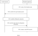
- FIG. 2 is a schematic diagram of another application scene according to some embodiments of the present disclosure.
- the peripheral apparatus 120 includes a first Bluetooth module and a WiFi module.
- the peripheral apparatus 120 may establish communication with a router through the WiFi module. That is, the peripheral apparatus 120 may need to support both WiFi and Bluetooth.
- the control terminal 110 includes a second Bluetooth module.
- the control terminal 110 may establish a Bluetooth connection with the first Bluetooth module of the peripheral apparatus 120 through the second Bluetooth module to implement the Bluetooth communication.
- the first Bluetooth module and the second Bluetooth module may be Bluetooth low energy (BLE) modules or standard Bluetooth modules.
- BLE Bluetooth low energy
- Embodiments of the present disclosure may provide a WiFi network access method, which enables the user to quickly configure the network of the peripheral apparatus, such as a printer.
- the printer can quickly be connected to the wireless network.
- the method may be described in detail in connection with the accompanying drawings.
- FIG. 3 is a schematic flowchart of a WiFi network access method according to some embodiments of the present disclosure. The method can be applied to the application scenes shown in FIG. 1 and FIG. 2 . As shown in FIG. 3 , the method includes the following processes.
- the first Bluetooth module enters a first broadcast state.
- the user may start the network configuration operation in the peripheral apparatus.
- the first Bluetooth module may be switched from a second broadcast state to the first broadcast state.
- a second type broadcast packet sent by the first Bluetooth module in the second broadcast state may be different from a first type broadcast packet.
- the user can start the peripheral apparatus to enter the network configuration state through a panel button of the peripheral apparatus.
- the first Bluetooth module may be switched from the second broadcast state to the first broadcast state.
- the first Bluetooth module when the peripheral apparatus is turned on the first time after leaving the factory, the first Bluetooth module may be turned on to enter the first broadcast state, which allows the user to quickly configure the wireless network for the peripheral apparatus. After the peripheral apparatus is configured to be connected to the wireless network, the first Bluetooth module may be switched to the second broadcast state, which can be used for interaction of other messages. When the user needs to reconfigure the wireless network for the peripheral apparatus, the broadcast state of the first Bluetooth module may be started or switched to enter the first broadcast state through a push button.
- the peripheral apparatus may enter the second broadcast state, the second type broadcast packet may be sent.
- the second type broadcast packet may not include recognition information.
- the control terminal may detect the peripheral apparatus and establish the Bluetooth connection to perform information interaction.
- the peripheral apparatus when the peripheral apparatus is in the second broadcast state, only the Bluetooth connection may be established for information interaction, and the information interaction of the network configuration may not be realized.
- the first Bluetooth module when the WiFi module of the peripheral apparatus is turned on and connected to the router, the first Bluetooth module may be in the second broadcast state.
- the WiFi module of the peripheral apparatus when the WiFi module of the peripheral apparatus is turned on and is not connected to the router, the first Bluetooth module may be set to automatically enter the first broadcast state or to be started to enter the first broadcast state through a user key.
- an individual key in the peripheral apparatus, may be arranged to start the first Bluetooth module to enter the first broadcast state, or an existing key in the peripheral apparatus may be reused to start the first Bluetooth module to enter the first broadcast state, which is not limited by embodiments of the present disclosure.
- the first type broadcast packet is sent to the control terminal through the first Bluetooth module.
- the first Bluetooth module of the peripheral apparatus may broadcast the first type broadcast packet to the outside.
- the control terminal may enter a scanning state to obtain the first type broadcast packet through the second Bluetooth module.
- the first type broadcast packet may include service UUID, identification information of the peripheral apparatus, and a device ID.
- Service UUID can be used to identify whether the corresponding peripheral apparatus satisfies a communication protocol agreed between the control terminal and the peripheral apparatus.
- a plurality of BLE devices that broadcast the broadcast packets of the plurality of BLE devices may exist around a same control terminal. Thus, only the BLE device, which conforms to the agreed communication protocol may be displayed in the device list of the control terminal APP. A BLE device that does not conform to the agreed communication protocol may not be displayed.
- the control terminal may display the device ID of the peripheral apparatus first.
- the user can select the peripheral apparatus to perform a quick configuration on the peripheral apparatus to connect the peripheral apparatus to the wireless network.
- displaying the device ID of the peripheral apparatus first by the control terminal includes receiving the first type broadcast packet by the control terminal and displaying the device ID of the peripheral apparatus at a first position of the device list on a display interface according to the identification information of the peripheral apparatus.
- the broadcast data when the peripheral apparatus enters the first broadcast state, the broadcast data may be as follows. Broadcast Segment Value Service UUID Including FFD1 Manufacture Data Manufacturer ID ("PT"string, 2 byte) + Model no. (“M6700DW'string, 7byte) + Reserved segment (00, 13byte) +identify (uchar, 1 byte)
- Identify may be used to set a position to 1 after a predetermined key is clicked, which may last for 30s. After the control terminal recognizes the position, the peripheral apparatus may be first displayed in a search list.
- a Bluetooth connection is established between the peripheral apparatus and the control terminal.
- the device ID of the peripheral apparatus may be displayed at the first position of the device list on the display interface of the terminal device.
- the user may trigger the Bluetooth connection between the peripheral apparatus and the control terminal by clicking the device ID of the peripheral apparatus.
- the Bluetooth connection may be the connection between the first Bluetooth module of the peripheral apparatus and the second Bluetooth module of the terminal device.
- the router network configuration information is sent to the peripheral apparatus through the second Bluetooth module.
- the network configuration operation can be performed next.
- the network configuration operation may include selecting SSID of the router that needs to be connected at the control terminal by the user and entering a password. After the password is confirmed, the network configuration information may be sent to the peripheral apparatus through Bluetooth. Thus, the WiFi module of the peripheral apparatus may be connected to the wireless network.
- the Service may include the two features below.
- the data structure may be sent in packets with a maximum of 20 bytes per packet. In order to ensure that the packet is sent correctly. This feature may need to have write (with response) authority.
- the corresponding data structure may be as follows.
- the WiFi module may be connected to the WiFi network according to the router network configuration information.
- the peripheral apparatus may notify ILink_LinkSuccess to indicate that the network configuration is successful.
- ILink_LinkWiFiErr may be notified.
- the control terminal may prompt the user to modify the router information.
- FIG. 4 is a schematic flowchart of the WiFi network access method according to some embodiments of the present disclosure.
- the peripheral apparatus may be an image-forming device.
- the image-forming device may include the control module (the first Bluetooth module arranged on the control module) and the WiFi module.
- An APP may be installed on the control terminal.
- the control terminal can communicate with the image-forming device using the APP.
- the method includes the following processes.
- the user triggers the network configuration process by the control terminal.
- the user can trigger the network configuration process through the APP of the control terminal, and discover the image-forming device with the network to be configured through Bluetooth.
- the user triggers the network configuration process through the image-forming device.
- Process S401 and process S402 may not be represented in order.
- the first type broadcast packet may include the service UUID, the identification information of the printer, and the device ID.
- control terminal is configured to parse the first type broadcast packet to identify the image-forming device and display the device ID of the image-forming device at a front end of the Bluetooth search list according to the identification information.
- the user may first select the image-forming device.
- the control terminal may establish a Bluetooth connection with the image-forming device.
- the image-forming device may return two feature values of ssid_info and device_state to the control terminal.
- the two feature values of ssid_info and device_state may be returned to the APP of the control terminal.
- the control terminal writes the information (SSID and password) of the router that is to be connected by the user into ssid_info and sends ssid_info to the image-forming device.
- control terminal may send ssid_info to the first Bluetooth module of the image-forming device through the second Bluetooth module.
- the image-forming device sends ssid_info to the WiFi module.
- the first Bluetooth module of the image-forming device may send ssid_info to the WiFi module.
- the WiFi module may obtain the SSID and password according to ssid_info to be connect to the router.
- the image-forming device is configured to send device_state to the control terminal through the first Bluetooth module.
- device_state may be used to notify the control terminal of the state and result of the network configuration. For example, the network configuration is successful or fails.
- the information of the router may need to be sent in packets.
- the APP may be used to perform packet processing on SSID and password of the router and combine a total number of packets and a cyclic redundancy check (CRC) value of each packet into the first type data packet.
- CRC cyclic redundancy check
- the data of the first type data packet may be saved.
- the subsequent second type data packet may be distinguished according to the CRC check value of the first type data packet.
- the data carried by the second type data packet may be combined to restore the information of the router.
- the first type data packet may include the total number of data packets, 10, and 10 CRC check values.
- the image-forming device may be configured to perform checking according to the CRC value carried by the second type data packet and the stored CRC value of the first type data packet. If packet is determined to be correct, the packet may be saved. The second type data packet that is checked to be correct may be parsed to obtain SSID and password of the router.
- FIG. 5 is a schematic diagram of a type data packet division according to some embodiments of the present disclosure.
- a total number of packets is 1 byte.
- the CRC value is 2 bytes, and the data is 18 bytes.
- the total packet number, the CRC value, and/or the data may be set to other byte numbers, which are not limited by embodiments of the present disclosure.
- the super long information of the router can be divided into packets and sent.
- the data packets may be ensured to be transmitted safely.
- the WiFi network access method is described above. Based on the WiFi network access method, the present disclosure further provides a method for adding the peripheral apparatus to the control terminal after the peripheral apparatus is connected to the WiFi network.
- FIG. 6 is a schematic flowchart showing a method for adding a peripheral according to some embodiments of the present disclosure. As shown in FIG. 6 , the method includes the following processes.
- the user may click on the APP of the control terminal to add the device.
- Adding the device may include adding the peripheral apparatus.
- control terminal performs a search to display a list of devices that are searched (i.e., device list).
- the device list may include a Bluetooth-enabled device list and/or a networked device list.
- the device name of the peripheral apparatus whose predetermined button is pressed may be displayed at the front end in the device list.
- the wireless network connection may be established with the peripheral apparatus after the network configuration to add the peripheral apparatus.
- the device name of the peripheral apparatus whose predetermined button is pressed may be displayed at the front end in the device list, which is the same as described above.
- the control terminal may receive the first type broadcast packet or the second type broadcast packet.
- the control terminal may be configured to display the peripheral apparatus that sends the first type broadcast packet at the front end of the device list.
- the list of the device that is connected to the network may include the peripheral apparatus that is configured with the wireless network, or the peripheral apparatus that has been connected to the network in a wired manner, or the peripheral apparatus that establishes communication with a cloud server.
- the control terminal searches for the device that is connected to the network, all the peripheral apparatuses that are connected to a same local area network (LAN) may be searched in the LAN where the control terminal is connected to.
- the control terminal can be configured to search the cloud server for an online peripheral apparatus that establishes the communication with the cloud server through a cellular network or a wide area network and display the searched peripheral apparatus in the list of the device that is connected to the network.
- the control terminal can be quickly bounded to the peripheral apparatus.
- the user can use the Wi-Fi network of a cell phone to quickly search for the peripheral apparatus (such as image-forming device) connected to the same Wi-Fi network in the control terminal (such as the cell phone).
- the peripheral apparatus such as image-forming device
- the control terminal such as the cell phone.
- the user may search the peripheral apparatus with cloud communication.
- the user can add different peripheral apparatuses to realize a wide range of mobile printing communication.
- the displayed device list may further include the peripheral apparatus that sends SSID.
- the user may establish direct communication with the peripheral apparatus.
- the control terminal may be configured to transmit the router information to the peripheral apparatus that sends SSID.
- the peripheral apparatus that sends SSID may be connected to the wireless network. Then, the control terminal may establish the communication with the peripheral apparatus in the wireless network and perform the binding operation.
- establishing the direct communication between the control terminal and the peripheral apparatus may include establishing the direct communication between the control terminal with the APP of the peripheral apparatus or establishing a point-to-point connection with the peripheral apparatus through Wi-Fi Direct.
- the control terminal may display the searched peripheral apparatus.
- a list of the peripheral apparatus supporting Bluetooth and/or a list of the peripheral apparatus supporting WiFi or network may be displayed separately.
- the user can quickly identify a desired target device, rather than a device list that displays all the searched peripheral apparatuses, which causes a selection difficulty for the user.
- the first Bluetooth module of the peripheral apparatus may send a broadcast packet with a same protocol.
- the control terminal may be configured to parse the broadcast packet according to the Bluetooth protocol to obtain corresponding data.
- Bluetooth protocols supported by the peripheral apparatus and the control terminal are different, the peripheral apparatus and the control terminal cannot perform Bluetooth communication.
- embodiments of the present disclosure may provide a communication method.
- FIG. 7 is a schematic diagram of the communication method according to some embodiments of the present disclosure. The method can be applied to the application scenes shown in FIG. 1 and FIG. 2 . As shown in FIG. 7 , the method includes the following processes.
- the peripheral apparatus sends the first broadcast packet packaged according to a first Bluetooth protocol to the control terminal.
- the peripheral apparatus may support a plurality of Bluetooth protocols, e.g., the first Bluetooth protocol and a second Bluetooth protocol.
- the first Bluetooth protocol and the second Bluetooth protocol are described as examples, which are not limited by embodiments of the present disclosure.
- the peripheral apparatus may also support more than three Bluetooth protocols.
- the peripheral apparatus may package the first broadcast packet according to the first Bluetooth protocol.
- the first Bluetooth module may enable Bluetooth broadcasting and sends the first broadcast packet to the control terminal.
- the first Bluetooth protocol is a protocol supported by a first APP of the control terminal
- the first broadcast packet is parsed using the first APP.
- the control terminal may or may not support the first Bluetooth protocol.
- the first Bluetooth protocol is the protocol supported by the first APP of the control terminal
- the first APP may be used to parse the first broadcast packet. If the first Bluetooth protocol is a protocol that is not supported by the control terminal, the first APP may not be used to parse the first broadcast packet, and the first broadcast packet may be discarded.
- the peripheral apparatus sends a second broadcast packet packaged according to the second Bluetooth protocol to the control terminal.
- the peripheral apparatus can package the second broadcast packet according to the second Bluetooth protocol.
- the first Bluetooth module may enable the Bluetooth broadcasting and send the second broadcast packet to the control terminal.
- the peripheral apparatus may send the second broadcast packet after delaying a predetermined time, for example, 500 ms, 800 ms, etc., which is not limited by embodiments of the present disclosure.
- the second Bluetooth protocol is a protocol supported by a second APP of the control terminal
- the second broadcast packet is parsed using the second APP.
- the control terminal may or may not support the second Bluetooth protocol.
- the second Bluetooth protocol is the protocol supported by the second APP of the control terminal
- the second APP may be used to parse the second broadcast packet. If the second Bluetooth protocol is a protocol that is not supported by the control terminal, the second APP may not be used to parse the second broadcast packet, and the second broadcast packet may be discarded.
- the peripheral apparatus may support the plurality of Bluetooth protocols, which can improve the compatibility of the peripheral apparatus.
- the first broadcast packet and/or the second broadcast packet may include the first type broadcast packet and the second type broadcast packet.
- the first type broadcast packet may be only sent when the network is configured.
- the second type broadcast packet may be sent when the network is not configured to perform a normal Bluetooth communication.
- the user may start the network configuration operation in the peripheral apparatus.
- the first Bluetooth module may be switched from the second broadcast state to the first broadcast state.
- the first Bluetooth module may be configured to broadcast the first type broadcast packet packaged according to the first Bluetooth protocol to the control terminal.
- the first Bluetooth module may be configured to broadcast the second type broadcast packet packaged according to the first Bluetooth protocol to the control terminal.
- the first type of broadcast packet may be different from the second type broadcast packet. If the first Bluetooth protocol is the protocol supported by the first APP of the control terminal, the control terminal may use the first APP to parse the first type broadcast packet and the second type broadcast packet.
- the first broadcast packet and/or the second broadcast packet may include service UUID, identification information of the peripheral apparatus, and the device ID.
- Service UUID can be used to identify whether the corresponding peripheral apparatus conforms to the communication protocol agreed between the control terminal and the peripheral apparatus.
- a plurality of BLE devices that broadcast the broadcast packets of the plurality of BLE devices may exist around the same control terminal. Thus, only the BLE device, which conforms to the agreed communication protocol may be displayed in the device list of the control terminal APP. The BLE device that does not conform to the agreed communication protocol may not be displayed.
- the control terminal may display the device ID of the peripheral apparatus first. Thus, the user can select the peripheral apparatus to perform a quick configuration on the peripheral apparatus to connect the peripheral apparatus to the wireless network.
- the Bluetooth connection between the control terminal and the peripheral apparatus can be established according to the data obtained by parsing the first broadcast packet and/or the second broadcast packet.
- the control terminal may send the router network configuration information to the first Bluetooth module of the peripheral apparatus through the second Bluetooth module.
- the peripheral apparatus may be configured to connect the WiFi module to the WiFi network according to the router network configuration information.
- the router network configuration information when the router network configuration information (i.e., SSID and password of the router) exceeds predetermined bytes, the router network configuration information may need to be sent in packets.
- the control terminal may be used to perform packet processing on SSID and password of the router and combine the total number of packets and the cyclic redundancy check (CRC) value of each packet into the first type data packet.
- CRC cyclic redundancy check
- the data of the first type data packet After the image-forming device receives the first type data packet, the data of the first type data packet may be saved. The subsequent second type data packet may be distinguished according to the CRC check value of the first type data packet.
- the data carried by the second type data packet may be combined to restore the information of the router.
- the first type data packet may include the total number of data packets, 10, and 10 CRC check values.
- the image-forming device may be configured to perform checking according to the CRC value carried by the second type data packet and the stored CRC value of the first type data packet. If packet is determined to be correct, the packet may be saved. The second type data packet that is checked to be correct may be parsed to obtain SSID and password of the router. For the specific contents of the network configuration operation, references may be made to the description above, which are not repeated here.
- FIG. 8 is a schematic structural diagram of a peripheral apparatus 800 according to some embodiments of the present disclosure.
- the peripheral apparatus 800 includes a processor 801, a memory 802, and a communication unit 803, which communicate through one or more buses.
- a structure of the peripheral apparatus shown in the drawings does not form a limitation on embodiments of the present disclosure.
- the structure may be a bus-type structure or a star-shaped structure.
- the structure may also include more or fewer components than the structure shown in the drawings, or some components may be combined, or the components may be arranged differently.
- the communication unit 803 may be configured to establish a communication channel.
- the memory 802 can communicate with other devices to receive user data sent by the other devices or send the user data to the other devices.
- the processor 801 which is a control center of a storage device, may be configured to run or execute a software program and/or module stored in the memory 802 and call the data in the memory.to execute various functions of the electronic device and/or process the data by using various interfaces and lines to connect various components of the entire electronic device.
- the processor may be formed by an integrated circuit (IC), for example, by a single packaged IC or a plurality of packaged ICs with a same function or different functions.
- the processor 801 may include a central processing unit (CPU).
- the CPU may include a single computation core or a plurality of computation cores.
- the memory 802 may be used to store an execution instruction of the processor 801.
- the memory 802 may include any type of volatile or non-volatile storage device or a combination thereof, such as static random access memory (SRAM), electrically erasable programmable read-only memory (EEPROM), erasable programmable read-only memory (EPROM), programmable read-only memory (PROM), read-only memory (ROM), magnetic memory, flash memory, magnetic disk, or optical disk.
- SRAM static random access memory
- EEPROM electrically erasable programmable read-only memory
- EPROM erasable programmable read-only memory
- PROM programmable read-only memory
- ROM read-only memory
- the peripheral apparatus 800 may be enabled to execute some or all of the processes above.
- the present disclosure also provides a non-transitory computer storage medium.
- the computer storage medium can store a program and, when the program is executed, causes the processor to perform some or all of the processes of the method of embodiments of the present disclosure.
- the storage medium may include a magnetic disk, an optical disk, a read-only memory (ROM), a random access memory (RAM), etc.
- "at least one” may indicate one or more, and "a plurality of” may indicate two or more.
- "And/or" which describes the association relationship of the associated objects, may indicate three kinds of relationships. For example, A and/or B, which can indicate A alone, A and B, and B alone. A and B can be singular or plural.
- the character "/” may generally indicate that the associated objects have an "or” relationship.
- "At least one of' and a similar expression may indicate any combination of these items, including any combination of single or plural items.
- At least one of a, b, or c may represent a, b, c, a-b, a-c, b-c, or a-b-c, where a, b, and c may be single or plural.
- any function is implemented in the form of a software functional unit and sold or used as an independent product, the function may be stored in a computer-readable storage medium.
- the computer software product may be stored in the storage medium, including some instructions that are used to cause a computer device (e.g., a personal computer, a server, or a network device, etc.) to execute all or part of the processes of the methods of embodiments of the present disclosure.
- the storage medium may include a U flash drive, mobile hard drive, read-only memory (ROM), random access memory (RAM), magnetic disk, optical disk, or another medium that can store program codes.
Landscapes
- Engineering & Computer Science (AREA)
- Computer Networks & Wireless Communication (AREA)
- Signal Processing (AREA)
- Mobile Radio Communication Systems (AREA)
Claims (10)
- WiFi-Netzwerkzugriffsverfahren, das an einer peripheren Vorrichtung (120, 800) angewendet wird, wobei die periphere Vorrichtung (120, 800) ein erstes Bluetooth-Modul und ein WiFi-Modul beinhaltet, das Verfahren umfassend:(S301) als Reaktion darauf, dass die periphere Vorrichtung (120, 800) in einen Netzwerkkonfigurationszustand eintritt, Eintreten in einen ersten Rundfunkzustand durch das erste Bluetooth-Modul;(S302) Senden eines Rundfunkpakets von einem ersten Typ an ein Steuerungsendgerät (110) über das erste Bluetooth-Modul, wobei das Rundfunkpaket vom ersten Typ eine Identifikationsinformation der peripheren Vorrichtung (120, 800) und eine Gerätekennung beinhaltet, wobei die Identifikationsinformation der peripheren Vorrichtung (120, 800) einem Benutzer ermöglicht, zuerst die periphere Vorrichtung (120, 800) auf einer Anzeigeoberfläche des Steuerungsendgeräts (110) zur Netzwerkkonfiguration auszuwählen;(S303, S405120, 800) Herstellen einer Bluetooth-Verbindung zwischen der peripheren Vorrichtung (120, 800) und dem Steuerungsendgerät (110);(S304) Empfangen von Router-Netzwerkkonfigurationsinformationen von dem Steuerungsendgerät (110) über das erste Bluetooth-Modul; und(S305) Verbinden des WiFi-Moduls mit einem WiFi-Netzwerk gemäß den Router-Netzwerkkonfigurationsinformationen, dadurch gekennzeichnet, dassdas Rundfunkpaket vom ersten Typ eine Dienst-UUID beinhaltet; undErmöglichen einem Benutzer, die periphere Vorrichtung (120, 800) durch den Benutzer auf der Anzeigeoberfläche des Steuerungsendgeräts (110) auszuwählen, beinhaltend:Klicken oder Drücken einer vorgegebenen Taste oder eines vorgegebenen Knopfs an der peripheren Vorrichtung (120, 800), um die Identifikationsinformation einzustellen, die angibt, dass die Gerätekennung der peripheren Vorrichtung (120, 800) an einer ersten Position einer Geräteliste der Anzeigeoberfläche angezeigt wird; undSenden des Rundfunkpakets vom ersten Typ an das Steuerungsendgerät (110), um das Rundfunkpaket vom ersten Typ zu analysieren, um die Identifikationsinformation zu erhalten;dadurch Veranlassen des Steuerungsendgeräts (110), die Gerätekennung der peripheren Vorrichtung (120, 800) an der ersten Position der Geräteliste der Anzeigeoberfläche zuerst gemäß der Identifikationsinformation der peripheren Vorrichtung (120, 800) anzuzeigen.
- Verfahren nach Anspruch 1, wobei in Reaktion darauf, dass die periphere Vorrichtung (120, 800) in den Netzwerkkonfigurationszustand eintritt, Veranlassen des Bluetooth-Moduls, in den ersten Rundfunkzustand einzutreten, Folgendes beinhaltet:
Starten eines Netzwerkkonfigurationsbetriebs in der peripheren Vorrichtung (120, 800), wobei das erste Bluetooth-Modul von einem zweiten Rundfunkzustand zu dem ersten Rundfunkzustand geschaltet wird, wobei sich ein Rundfunkpaket vom zweiten Typ, das von dem ersten Bluetooth-Modul in dem zweiten Rundfunkzustand gesendet wird, von dem Rundfunkpaket vom ersten Typ unterscheidet. - Verfahren nach Anspruch 1, wobei Empfangen der Router-Netzwerkkonfigurationsinformationen von dem Steuerungsendgerät (110) über das erste Bluetooth-Modul Folgendes beinhaltet:Empfangen eines ersten Datenpakets, wobei das erste Datenpaket eine Gesamtzahl von Paketen und einen Prüfwert der Pakete beinhaltet;Empfangen eines zweiten Datenpakets;Bestimmen, ob das zweite Datenpaket gemäß dem Prüfwert des ersten Datenpakets korrekt ist; undals Reaktion darauf, dass das zweite Datenpaket korrekt ist, Analysieren des zweiten Datenpakets, um die Router-Netzwerkkonfigurationsinformationen zu erhalten.
- WiFi-Netzwerkzugriffsverfahren, das auf ein Steuerungsendgerät (110) angewendet wird, wobei das Steuerungsendgerät (110) ein zweites Bluetooth-Modul beinhaltet, wobei das Verfahren Folgendes umfasst:
Erhalten einer Identifikationsinformation einer peripheren Vorrichtung (120, 800) über ein zweites Bluetooth-Modul, beinhaltend:Steuern des Steuerungsendgeräts (110), in einen Abtastungszustand einzutreten, um ein Rundfunkpaket vom ersten Typ zu erhalten, das von der peripheren Vorrichtung (120, 800) gesendet wurde, wobei das Rundfunkpaket vom ersten Typ die Identifikationsinformation der peripheren Vorrichtung (120, 800) und eine Gerätekennung beinhaltet, wobei die Identifikationsinformation der peripheren Vorrichtung (120, 800) einem Benutzer ermöglicht, zuerst die periphere Vorrichtung (120, 800) auf einer Anzeigeoberfläche des Steuerungsendgeräts (110) zur Netzwerkkonfiguration auszuwählen; undHerstellen der Bluetooth-Verbindung mit der peripheren Vorrichtung (120, 800) gemäß einer Benutzerauswahl, um die Router-Netzwerkkonfigurationsinformationen an die periphere Vorrichtung (120, 800) zu senden; dadurch gekennzeichnet, dassdas Rundfunkpaket vom ersten Typ eine Dienst-UUID beinhaltet; undAuswählen der peripheren Vorrichtung (120, 800) durch den Benutzer auf der Anzeigeoberfläche des Steuerungsendgeräts (110) Folgendes beinhaltet:Empfangen des Rundfunkpakets vom ersten Typ durch das Steuerungsendgerät (110) und Analysieren des Rundfunkpakets vom ersten Typ, um die Identifikationsinformation zu erhalten, die angibt, dass eine vorgegebene Taste oder ein vorgegebener Knopf an der peripheren Vorrichtung (120, 800) geklickt oder gedrückt worden ist, um die Gerätekennung der peripheren Vorrichtung (120, 800) zu veranlassen, an einer ersten Position einer Geräteliste der Anzeigeoberfläche angezeigt zu werden; undAnzeigen der Gerätekennung der peripheren Vorrichtung (120, 800) an der ersten Position der Geräteliste der Anzeigeoberfläche zuerst gemäß der Identifikationsinformation der peripheren Vorrichtung (120, 800). - Verfahren nach Anspruch 4, weiter umfassend:Empfangen einer Nachricht zur erfolgreichen Netzwerkverbindung, die von der peripheren Vorrichtung (120, 800) retourniert wird; undSenden eines Trennungsbefehls an die periphere Vorrichtung (120, 800), um die Bluetooth-Verbindung von der peripheren Vorrichtung (120, 800) zu trennen.
- Verfahren nach Anspruch 4, wobei Senden der Router-Netzwerkkonfigurationsinformationen an die periphere Vorrichtung (120, 800) Folgendes beinhaltet:Senden eines ersten Datenpakets, wobei das erste Datenpaket eine Gesamtzahl von Paketen und einen Prüfwert der Pakete beinhaltet;Senden eines zweiten Datenpakets;Bestimmen, ob das zweite Datenpaket gemäß dem Prüfwert des ersten Datenpakets korrekt ist, durch die periphere Vorrichtung (120, 800); undals Reaktion darauf, dass das zweite Datenpaket korrekt ist, Analysieren des zweiten Datenpakets, um die Router-Netzwerkkonfigurationsinformationen zu erhalten.
- Verfahren nach Anspruch 4, wobei:die Geräteliste der Anzeigeoberfläche weiter eine periphere Vorrichtung (120, 800) beinhaltet, die eine SSID sendet; undals Reaktion darauf, dass der Benutzer die periphere Vorrichtung (120, 800) auswählt, die die SSID sendet, eine direkte Kommunikation mit der peripheren Vorrichtung (120, 800) hergestellt wird, um die Router-Netzwerkkonfigurationsinformationen an die periphere Vorrichtung (120, 800) zu senden.
- Periphere Vorrichtung (120, 800), umfassend: einen Speicher (802), der ein Computerprogramm speichert; und einen Prozessor (801), der mit dem Speicher (802) gekoppelt ist, und, wenn das Computerprogramm von dem Prozessor (801) ausgeführt wird, dazu konfiguriert ist, das Verfahren nach einem der Ansprüche 1 bis 3 durchzuführen.
- Nichtflüchtiges computerlesbares Speichermedium, das ein Computerprogramm speichert, das, wenn es von einem Prozessor (801) ausgeführt wird, den Prozessor (801) dazu veranlasst, das Verfahren nach einem der Ansprüche 1 bis 3 durchzuführen.
- Nichtflüchtiges computerlesbares Speichermedium, das ein Computerprogramm speichert, das, wenn es von einem Prozessor (801) ausgeführt wird, den Prozessor (801) dazu veranlasst, das Verfahren nach einem der Ansprüche 4 bis 7 durchzuführen.
Applications Claiming Priority (2)
| Application Number | Priority Date | Filing Date | Title |
|---|---|---|---|
| CN202111257540 | 2021-10-27 | ||
| CN202210532260.8A CN114980266B (zh) | 2021-10-27 | 2022-04-27 | WiFi入网方法、通信方法、外围设备和存储介质 |
Publications (3)
| Publication Number | Publication Date |
|---|---|
| EP4175335A1 EP4175335A1 (de) | 2023-05-03 |
| EP4175335B1 true EP4175335B1 (de) | 2024-10-16 |
| EP4175335C0 EP4175335C0 (de) | 2024-10-16 |
Family
ID=84332346
Family Applications (1)
| Application Number | Title | Priority Date | Filing Date |
|---|---|---|---|
| EP22203457.1A Active EP4175335B1 (de) | 2021-10-27 | 2022-10-25 | Zugangsverfahren für wifi-netzwerk, peripherievorrichtung und speichermedium |
Country Status (2)
| Country | Link |
|---|---|
| US (1) | US20230126360A1 (de) |
| EP (1) | EP4175335B1 (de) |
Families Citing this family (1)
| Publication number | Priority date | Publication date | Assignee | Title |
|---|---|---|---|---|
| CN115460674A (zh) | 2022-09-19 | 2022-12-09 | 珠海奔图电子有限公司 | 配网方法和装置 |
Family Cites Families (2)
| Publication number | Priority date | Publication date | Assignee | Title |
|---|---|---|---|---|
| US9961484B2 (en) * | 2016-01-22 | 2018-05-01 | Lg Electronics Inc. | Method and apparatus for controlling a device using bluetooth technology |
| US12238003B2 (en) * | 2016-07-05 | 2025-02-25 | Six Impossible Things Before Breakfast Limited | Systems, apparatuses and methods for cooperating routers |
-
2022
- 2022-10-25 EP EP22203457.1A patent/EP4175335B1/de active Active
- 2022-10-26 US US17/974,270 patent/US20230126360A1/en active Pending
Also Published As
| Publication number | Publication date |
|---|---|
| EP4175335A1 (de) | 2023-05-03 |
| US20230126360A1 (en) | 2023-04-27 |
| EP4175335C0 (de) | 2024-10-16 |
Similar Documents
| Publication | Publication Date | Title |
|---|---|---|
| EP3621358B1 (de) | Endgerätevorrichtung und nichttransitorisches computerlesbares speichermedium mit darauf gespeichertem speicherprogramm | |
| US9860417B2 (en) | Communication apparatus | |
| US9942759B2 (en) | Communication apparatus | |
| US20170290071A1 (en) | Information processing apparatus, control method, and non-transitory computer-readable storage medium | |
| CN114980266B (zh) | WiFi入网方法、通信方法、外围设备和存储介质 | |
| CN107920354A (zh) | 多频段设备连接方法及系统 | |
| US9338818B2 (en) | Wireless communication apparatus for wireless network and computer readable media | |
| US10382923B2 (en) | Communication apparatus capable of preventing data erroneous transmission, control method therefor, and storage medium storing control program therefor | |
| US20050270989A1 (en) | Method and apparatus for automatically configuring wireless network device | |
| US11099797B2 (en) | Non-transitory computer-readable recording medium storing computer-readable instructions for establishing wireless connection between terminal device and communication device | |
| EP4175335B1 (de) | Zugangsverfahren für wifi-netzwerk, peripherievorrichtung und speichermedium | |
| EP3267656B1 (de) | Verfahren und vorrichtungen zur nachrichtenverarbeitung während einer pppoe-authentifizierung | |
| US10289360B2 (en) | Information processing apparatus, control method and recording medium | |
| US12452675B2 (en) | Bluetooth connection | |
| JP7196248B2 (ja) | 通信装置、制御方法及びプログラム | |
| US7702793B2 (en) | Method and apparatus for setting network using DHCP server or client function | |
| US10719281B2 (en) | Communication terminal, method of controlling communication terminal, and non-transitory computer-readable recording medium therefor | |
| CN115733745A (zh) | 灵活以太网业务传输配置的生成方法和装置 | |
| US20200245245A1 (en) | Information processing device, wireless terminal, and non-transitory computer-readable medium | |
| US20250294439A1 (en) | Communication device, image processing device, and non-transitory computer-readable recording medium storing computer-readable instructions for communication device and image processing device | |
| CN111490910A (zh) | 设备信息的扫描方法、终端设备及计算机可读存储介质 | |
| EP4468788A1 (de) | Wi-fi p2p verbindungsverfahren, vorrichtung und system | |
| US20250294438A1 (en) | Communication device, image processing device, and non-transitory computer-readable recording medium storing computer-readable instructions for communication device and image processing device | |
| US20230421438A1 (en) | Information processing apparatus, control method of the same, and non-transitory computer-readable storage medium | |
| CN113890839B (zh) | 物联网设备的网络连接状态的确定方法及装置 |
Legal Events
| Date | Code | Title | Description |
|---|---|---|---|
| PUAI | Public reference made under article 153(3) epc to a published international application that has entered the european phase |
Free format text: ORIGINAL CODE: 0009012 |
|
| STAA | Information on the status of an ep patent application or granted ep patent |
Free format text: STATUS: REQUEST FOR EXAMINATION WAS MADE |
|
| 17P | Request for examination filed |
Effective date: 20230330 |
|
| AK | Designated contracting states |
Kind code of ref document: A1 Designated state(s): AL AT BE BG CH CY CZ DE DK EE ES FI FR GB GR HR HU IE IS IT LI LT LU LV MC ME MK MT NL NO PL PT RO RS SE SI SK SM TR |
|
| STAA | Information on the status of an ep patent application or granted ep patent |
Free format text: STATUS: EXAMINATION IS IN PROGRESS |
|
| 17Q | First examination report despatched |
Effective date: 20231212 |
|
| GRAP | Despatch of communication of intention to grant a patent |
Free format text: ORIGINAL CODE: EPIDOSNIGR1 |
|
| STAA | Information on the status of an ep patent application or granted ep patent |
Free format text: STATUS: GRANT OF PATENT IS INTENDED |
|
| INTG | Intention to grant announced |
Effective date: 20240517 |
|
| GRAS | Grant fee paid |
Free format text: ORIGINAL CODE: EPIDOSNIGR3 |
|
| GRAA | (expected) grant |
Free format text: ORIGINAL CODE: 0009210 |
|
| STAA | Information on the status of an ep patent application or granted ep patent |
Free format text: STATUS: THE PATENT HAS BEEN GRANTED |
|
| AK | Designated contracting states |
Kind code of ref document: B1 Designated state(s): AL AT BE BG CH CY CZ DE DK EE ES FI FR GB GR HR HU IE IS IT LI LT LU LV MC ME MK MT NL NO PL PT RO RS SE SI SK SM TR |
|
| REG | Reference to a national code |
Ref country code: GB Ref legal event code: FG4D |
|
| REG | Reference to a national code |
Ref country code: CH Ref legal event code: EP |
|
| REG | Reference to a national code |
Ref country code: IE Ref legal event code: FG4D |
|
| REG | Reference to a national code |
Ref country code: DE Ref legal event code: R096 Ref document number: 602022006834 Country of ref document: DE |
|
| U01 | Request for unitary effect filed |
Effective date: 20241031 |
|
| U07 | Unitary effect registered |
Designated state(s): AT BE BG DE DK EE FI FR IT LT LU LV MT NL PT RO SE SI Effective date: 20241112 |
|
| U20 | Renewal fee for the european patent with unitary effect paid |
Year of fee payment: 3 Effective date: 20241227 |
|
| PG25 | Lapsed in a contracting state [announced via postgrant information from national office to epo] |
Ref country code: HR Free format text: LAPSE BECAUSE OF FAILURE TO SUBMIT A TRANSLATION OF THE DESCRIPTION OR TO PAY THE FEE WITHIN THE PRESCRIBED TIME-LIMIT Effective date: 20241016 Ref country code: IS Free format text: LAPSE BECAUSE OF FAILURE TO SUBMIT A TRANSLATION OF THE DESCRIPTION OR TO PAY THE FEE WITHIN THE PRESCRIBED TIME-LIMIT Effective date: 20250216 |
|
| PG25 | Lapsed in a contracting state [announced via postgrant information from national office to epo] |
Ref country code: ES Free format text: LAPSE BECAUSE OF FAILURE TO SUBMIT A TRANSLATION OF THE DESCRIPTION OR TO PAY THE FEE WITHIN THE PRESCRIBED TIME-LIMIT Effective date: 20241016 |
|
| PG25 | Lapsed in a contracting state [announced via postgrant information from national office to epo] |
Ref country code: NO Free format text: LAPSE BECAUSE OF FAILURE TO SUBMIT A TRANSLATION OF THE DESCRIPTION OR TO PAY THE FEE WITHIN THE PRESCRIBED TIME-LIMIT Effective date: 20250116 |
|
| PG25 | Lapsed in a contracting state [announced via postgrant information from national office to epo] |
Ref country code: GR Free format text: LAPSE BECAUSE OF FAILURE TO SUBMIT A TRANSLATION OF THE DESCRIPTION OR TO PAY THE FEE WITHIN THE PRESCRIBED TIME-LIMIT Effective date: 20250117 |
|
| PG25 | Lapsed in a contracting state [announced via postgrant information from national office to epo] |
Ref country code: PL Free format text: LAPSE BECAUSE OF FAILURE TO SUBMIT A TRANSLATION OF THE DESCRIPTION OR TO PAY THE FEE WITHIN THE PRESCRIBED TIME-LIMIT Effective date: 20241016 |
|
| PG25 | Lapsed in a contracting state [announced via postgrant information from national office to epo] |
Ref country code: RS Free format text: LAPSE BECAUSE OF FAILURE TO SUBMIT A TRANSLATION OF THE DESCRIPTION OR TO PAY THE FEE WITHIN THE PRESCRIBED TIME-LIMIT Effective date: 20250116 |
|
| PG25 | Lapsed in a contracting state [announced via postgrant information from national office to epo] |
Ref country code: SM Free format text: LAPSE BECAUSE OF FAILURE TO SUBMIT A TRANSLATION OF THE DESCRIPTION OR TO PAY THE FEE WITHIN THE PRESCRIBED TIME-LIMIT Effective date: 20241016 |
|
| PG25 | Lapsed in a contracting state [announced via postgrant information from national office to epo] |
Ref country code: MC Free format text: LAPSE BECAUSE OF FAILURE TO SUBMIT A TRANSLATION OF THE DESCRIPTION OR TO PAY THE FEE WITHIN THE PRESCRIBED TIME-LIMIT Effective date: 20241016 |
|
| PG25 | Lapsed in a contracting state [announced via postgrant information from national office to epo] |
Ref country code: SK Free format text: LAPSE BECAUSE OF FAILURE TO SUBMIT A TRANSLATION OF THE DESCRIPTION OR TO PAY THE FEE WITHIN THE PRESCRIBED TIME-LIMIT Effective date: 20241016 |
|
| PG25 | Lapsed in a contracting state [announced via postgrant information from national office to epo] |
Ref country code: CZ Free format text: LAPSE BECAUSE OF FAILURE TO SUBMIT A TRANSLATION OF THE DESCRIPTION OR TO PAY THE FEE WITHIN THE PRESCRIBED TIME-LIMIT Effective date: 20241016 |
|
| PLBE | No opposition filed within time limit |
Free format text: ORIGINAL CODE: 0009261 |
|
| STAA | Information on the status of an ep patent application or granted ep patent |
Free format text: STATUS: NO OPPOSITION FILED WITHIN TIME LIMIT |
|
| 26N | No opposition filed |
Effective date: 20250717 |
|
| PG25 | Lapsed in a contracting state [announced via postgrant information from national office to epo] |
Ref country code: IE Free format text: LAPSE BECAUSE OF NON-PAYMENT OF DUE FEES Effective date: 20241025 |
|
| U20 | Renewal fee for the european patent with unitary effect paid |
Year of fee payment: 4 Effective date: 20251028 |
|
| PG25 | Lapsed in a contracting state [announced via postgrant information from national office to epo] |
Ref country code: CY Free format text: LAPSE BECAUSE OF FAILURE TO SUBMIT A TRANSLATION OF THE DESCRIPTION OR TO PAY THE FEE WITHIN THE PRESCRIBED TIME-LIMIT; INVALID AB INITIO Effective date: 20221025 |