EP4175314A1 - Microphone device with a closed housing and a membrane - Google Patents
Microphone device with a closed housing and a membrane Download PDFInfo
- Publication number
- EP4175314A1 EP4175314A1 EP21204796.3A EP21204796A EP4175314A1 EP 4175314 A1 EP4175314 A1 EP 4175314A1 EP 21204796 A EP21204796 A EP 21204796A EP 4175314 A1 EP4175314 A1 EP 4175314A1
- Authority
- EP
- European Patent Office
- Prior art keywords
- microphone
- sidewall
- housing
- membrane
- cavity
- Prior art date
- Legal status (The legal status is an assumption and is not a legal conclusion. Google has not performed a legal analysis and makes no representation as to the accuracy of the status listed.)
- Pending
Links
Images


Classifications
-
- H—ELECTRICITY
- H04—ELECTRIC COMMUNICATION TECHNIQUE
- H04R—LOUDSPEAKERS, MICROPHONES, GRAMOPHONE PICK-UPS OR LIKE ACOUSTIC ELECTROMECHANICAL TRANSDUCERS; ELECTRIC HEARING AIDS; PUBLIC ADDRESS SYSTEMS
- H04R1/00—Details of transducers, loudspeakers or microphones
- H04R1/02—Casings; Cabinets ; Supports therefor; Mountings therein
-
- H—ELECTRICITY
- H04—ELECTRIC COMMUNICATION TECHNIQUE
- H04R—LOUDSPEAKERS, MICROPHONES, GRAMOPHONE PICK-UPS OR LIKE ACOUSTIC ELECTROMECHANICAL TRANSDUCERS; ELECTRIC HEARING AIDS; PUBLIC ADDRESS SYSTEMS
- H04R1/00—Details of transducers, loudspeakers or microphones
- H04R1/08—Mouthpieces; Microphones; Attachments therefor
- H04R1/083—Special constructions of mouthpieces
- H04R1/086—Protective screens, e.g. all weather or wind screens
-
- H—ELECTRICITY
- H04—ELECTRIC COMMUNICATION TECHNIQUE
- H04R—LOUDSPEAKERS, MICROPHONES, GRAMOPHONE PICK-UPS OR LIKE ACOUSTIC ELECTROMECHANICAL TRANSDUCERS; ELECTRIC HEARING AIDS; PUBLIC ADDRESS SYSTEMS
- H04R1/00—Details of transducers, loudspeakers or microphones
- H04R1/08—Mouthpieces; Microphones; Attachments therefor
-
- H—ELECTRICITY
- H04—ELECTRIC COMMUNICATION TECHNIQUE
- H04R—LOUDSPEAKERS, MICROPHONES, GRAMOPHONE PICK-UPS OR LIKE ACOUSTIC ELECTROMECHANICAL TRANSDUCERS; ELECTRIC HEARING AIDS; PUBLIC ADDRESS SYSTEMS
- H04R1/00—Details of transducers, loudspeakers or microphones
- H04R1/02—Casings; Cabinets ; Supports therefor; Mountings therein
- H04R1/021—Casings; Cabinets ; Supports therefor; Mountings therein incorporating only one transducer
-
- H—ELECTRICITY
- H04—ELECTRIC COMMUNICATION TECHNIQUE
- H04R—LOUDSPEAKERS, MICROPHONES, GRAMOPHONE PICK-UPS OR LIKE ACOUSTIC ELECTROMECHANICAL TRANSDUCERS; ELECTRIC HEARING AIDS; PUBLIC ADDRESS SYSTEMS
- H04R2201/00—Details of transducers, loudspeakers or microphones covered by H04R1/00 but not provided for in any of its subgroups
- H04R2201/003—Mems transducers or their use
-
- H—ELECTRICITY
- H04—ELECTRIC COMMUNICATION TECHNIQUE
- H04R—LOUDSPEAKERS, MICROPHONES, GRAMOPHONE PICK-UPS OR LIKE ACOUSTIC ELECTROMECHANICAL TRANSDUCERS; ELECTRIC HEARING AIDS; PUBLIC ADDRESS SYSTEMS
- H04R2499/00—Aspects covered by H04R or H04S not otherwise provided for in their subgroups
- H04R2499/10—General applications
- H04R2499/13—Acoustic transducers and sound field adaptation in vehicles
Definitions
- the present disclosure relates to a microphone device and a method for generating the device.
- the disclosure relates to methods and systems for protecting microphones from water and solid particles at IP69K standard.
- IP69K IP69K
- a system is required to withstand exposure to water at high-pressure and high temperature. For example, a car may be exposed to such conditions when hit by a water jet for car washing or similar.
- any such exposures could lead to a malfunction of the sensors such as a microphone, and thereby to a malfunction of the vehicle or a loss of safety for the occupants.
- the level of autonomous driving could decrease and require human interaction or a sensor malfunction could force a complete stop of vehicle.
- a first aspect of the present disclosure relates to a microphone device.
- the microphone device comprises a closed housing with a sidewall, a microphone arranged within the closed housing, and a membrane at an outer surface of the sidewall, wherein a first part of the sidewall has a first thickness and wherein the membrane is comprised by, in particular is formed by, a second part of the sidewall having a second thickness smaller than the first thickness.
- the microphone device allows protecting a microphone against external entities such as water or dust particles.
- the device enables a protection at high level standards, in particular IP69K, due to the use of a closed housing, i.e. a housing without openings.
- a closed housing may thus also be referred to as a waterproof housing.
- sound waves reaching the microphone by air or holes in the housing - through which also water and dust can enter - the sound is transmitted and/or reflected from the outside to the inside of the housing by membrane parts in the housing.
- the sound waves which hit the membrane area generate a vibration of this specific area of the housing and a new sound wave is created inside the microphone housing. This new sound wave then reaches the microphone.
- the microphone element may be a micro-electro-mechanical system (MEMS) microphone and situated on a printed circuit board, PCB, inside the housing. The sound may then reach the microphone through a port hole inside the PCB.
- MEMS micro-electro-mechanical system
- the microphone element may alternatively be a top-ported MEMS microphone, wherein the microphone is situated on a PCB facing the membrane.
- the microphone element may comprise other microphone sensor, for instance in an ECM capsule architecture.
- the thickness of the sound transfer area may be determined by the acoustical and mechanical properties of the intended material of the housing. Thus, the material selection may influence or determine the performance of the microphone.
- the sidewall of the housing may be formed in one piece.
- the membrane is formed by a thinner part of the sidewall of the housing.
- the housing has no openings through which water and/or dust particles may enter.
- no additional integration of an external membrane through, for example, adhesion or sealed attachment is necessary. This further reduces the risk of producing openings in the housing.
- a cavity is arranged between the membrane and the microphone, in particular wherein the second part of the sidewall is arranged adjacent to the cavity and/or wherein the cavity is arranged within the sidewall.
- the size and/or form of the cavity may be chosen such that the transmission of the sound from the outside of the housing to the microphone is optimized.
- the membrane covers the cavity.
- the membrane may be formed by a thinner area of the sidewall of the housing as describes above.
- the membrane may alternatively be an additional, external membrane.
- the cavity may be comprised by a hole in the sidewall of the housing.
- the external membrane covers the cavity, i.e. the hole, within the sidewall of the housing. This also results in a closed housing without holes through which water and/or dust particles may enter the housing.
- the use of an external membrane allows choosing different materials for the membrane and the housing. Thereby, for example, suitable material for a good sound wave transmission/reflection may be chosen for membrane, while suitable materials with, for example, good mechanical properties may be chosen for the housing. Further, materials can be exploited as membranes, for which a necessary membrane thickness not easily achieved by production methods for the housing.
- the external membranes may be applied sealed to the sidewall of the housing enabling an enclosed housing without openings.
- the microphone device further comprises at least one support element, wherein the at least one support element retains the microphone at a fixed position relative to the housing and/or the sidewall of the housing.
- the at least one support element is arranged between the microphone and the membrane. Thereby, within the housing, the sound wave may propagate through (an opening of) the at least one support element.
- the cavity is confined by the sidewall of the closed housing, in particular by the second part of the sidewall of the housing, and the one or more support elements.
- the microphone is situated at a fixed position within the housing by a support element.
- An exemplary support element may be a printed circuit board, PCB.
- PCB printed circuit board
- a first support element may be a PCB holding the microphone and a second support element may be a plastic or elastomer element with a cylindrical or conical shape and/or a cylindrically or conically shaped opening enclosing the cavity between the membrane area and the PCB.
- a plastic or elastomer element with a cylindrical or conical shape and/or a cylindrically or conically shaped opening enclosing the cavity between the membrane area and the PCB.
- the at least one support element seals the cavity against an inner space of the housing.
- the support element may be a plastic element with a cylindrical or conical opening enclosing the cavity.
- the support element may protect the cavity from water and/or particles coming in and avoids sound waves exiting the cavity into other areas within the housing. Thereby, the support element defines the space for wave transmission.
- At least a part of the at least one support element is embedded within the sidewall of the housing, in particular within the cavity. This enables a sealed implementation of the support element(s) and improves mechanical stability of the microphone device, in particular of the sidewall of the housing.
- the microphone is arranged on the at least one support element opposite the membrane and/or adjacent to the cavity and/or the at least one support element comprises an opening between the cavity and the microphone.
- the support element may be a PCB and the opening between the cavity and the microphone may be port hole in the PCB. Positioning the support element opposite to the membrane and adjacent to the cavity enables an enclosed space for wave transmission.
- the cavity and/or the at least one support element has a conical or cylindrical shape.
- the shape may determine the sound transmission within the cavity and/or the at least one support element. Changing the shape enables, for example, tuning of the frequency response within the cavity and/or the at least one support element.
- the at least one support element is made of plastic or rubber.
- the use of elastomeric materials allows for an easy, sealed integration of the support element between the inner sidewall of housing and the microphone or another support element, for example a PCB holding the microphone or any other casing of the microphone.
- the invention further comprises, according to an embodiment a plurality of microphones arranged as a microphone array.
- the microphone array may comprise any number of microphones operating in tandem. Microphone arrays allow for better extraction of sound input from ambient noise and/or enable the localization of acoustic sources.
- each of the microphones of the microphone array is opposed by a respective one of a plurality of membranes and, preferably, by a respective one of a plurality of cavities. Thereby, each microphone is protected. Further, the sound transmission through the membrane and the cavity may be adjusted for each microphone. For example, the direction of incoming sound waves can be detected.
- the method comprises providing a closed housing with a sidewall, providing a membrane at an outer surface of the sidewall and placing a microphone within the housing, wherein a first part of the sidewall has a first thickness and wherein the membrane is comprised by, in particular is formed by, a second part of the sidewall having a second thickness smaller than the first thickness.
- the method further comprises forming a cavity within the sidewall of the housing, in particular wherein the cavity is arranged between the microphone and the membrane. All properties of the microphone device of the present disclosure also apply to the method.
- FIG. 1 depicts a schematic of a first microphone device.
- the microphone device 100 comprises a closed housing 102 with a sidewall 104 and a microphone 106 arranged within the closed housing 102.
- the microphone 106 may be a MEMS microphone.
- a membrane 108 is situated at the outer of surface of the sidewall 104.
- a cavity 110 is located between the membrane 108 and the microphone 106.
- the cavity 110 is located within the sidewall 104 of the closed housing 102.
- the distance between the cavity 110 and the microphone 106 may be below 2 mm, for example 1.6 mm.
- the cavity 110 may be filled with air.
- a first part 112 of the sidewall 104 has a first thickness. The first thickness may be in the range of 1 - 2 millimeters.
- the membrane 108 may be comprised by, or in particular formed by, a second part 114 of the sidewall 104.
- the second part 104 of the sidewall may have a thickness below 1 mm, in particular between 0.2 mm and 0.8 mm, more particularly of 0.4 mm.
- the second part of the sidewall covers the cavity 110 within the housing 102.
- the second part may have a lateral size between 0.5 cm and 1.5 cm, in particular a diameter or side length of 10 mm or 12 mm.
- the second part 114 forming the membrane 108 and sidewall 104 may be made of the same material, for example, one of a polymeric material, metallic material, steel, glass or a composite material.
- the microphone device further comprises two support elements 116, 118.
- the first support element 118 retains the microphone 106 at a fix position relative to the housing102.
- the first support elements may comprise a printed circuit board, PCB, which covers the microphone and forms spaces for other devices, such as MEMS devices.
- the first support element118 comprise a port hole 122 forming a channel between the cavity 110 and the microphone 106.
- the microphone device comprises a second support element 116.
- the second support element 116 confines the cavity 110 between the membrane 108 and the microphone 106 or between the membrane 108 and the first support element 118.
- the second support element 116 seals the cavity 110 against an inner space 120 of the housing 102.
- the second support element 116 is partially embedded within the sidewall 104 of the housing, more particularly within the cavity 110.
- the cavity 110 may have a conical or cylindrical shape.
- the second support element enclosing the cavity may be of plastic or elastomer or another polymeric material.
- Figure 2 depicts a schematic of the working principle of the microphone device.
- An outer sound wave 202 hits the membrane 108 of the sidewall. The sound wave is then transmitted via the membrane 108 into the cavity 110. This inner sound wave 204 may then enter the microphone 106.
- the shape of the support elements 116 and 118 and the material of the support elements 116 and 118 may determine the frequency response within the cavity 110.
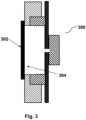
- Figure 3 depicts a second microphone device according to another embodiment.
- the sidewall 104 of the housing contains an opening 304.
- This opening 304 is adjacent to the cavity 110 within the housing.
- the opening 304 in the sidewall 104 is covered by an external membrane 302.
- the opening in the sidewall may be circular or rectangular.
- the opening 304 may have a lateral size between 0.5 cm and 1.5 cm, in particular a diameter or side length of 10 mm or 12 mm.
- the membrane 302 may be comprised by a different material than the sidewall of the housing.
- the membrane 302 may have a thickness below 1 mm, in particular between 0.2 mm and 0.8 mm.
- the membrane may be made of a polymeric material, metallic material, steel, glass or a composite material.
- the membrane 302 may be applied sealed to the sidewall 104. For example, the membrane 302 may be adhered to the sidewall or applied by injection molding.
- the microphone device may comprise a plurality of microphones 108 arranged as a microphone array.
- Each of the microphones 108 of the microphone array may be opposed by a respective one of a plurality of membranes 108 and a respect of one of a plurality of cavities 110.
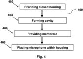
- Figure 4 depicts the flow diagram of a method for generating the microphone device 100 of any of the above embodiments.
- the method comprises providing a closed housing within the sidewall in step 402, forming a cavity within the sidewall of the housing in step 404, providing a membrane at an outer surface of the sidewall in step 406 and placing a microphone within the housing at step 408.
- the cavity is arranged between the microphone and the membrane.
Landscapes
- Physics & Mathematics (AREA)
- Engineering & Computer Science (AREA)
- Acoustics & Sound (AREA)
- Signal Processing (AREA)
- Details Of Audible-Bandwidth Transducers (AREA)
Abstract
Description
- The present disclosure relates to a microphone device and a method for generating the device. In particular, the disclosure relates to methods and systems for protecting microphones from water and solid particles at IP69K standard.
- With the growth of driving assistance technologies and autonomous driving vehicles, the amount of sensors in a car has grown extensively. Due to the development of these technologies, it has become necessary to detect sound from outside a vehicle such as emergency vehicles, pedestrians or events happening in the surroundings of the car. Therefore, a number of microphones on the exterior body or surface of the vehicle is required. These microphones must withstand the usage of the car in different driving scenarios. In particular, external entities including water, ice, dust or debris could potentially alter the performance of any sensor such as a microphone and thereby jeopardize, for instance, integrated safety systems of the vehicle.
- To enable a robust performance, it is desirable to achieve highest protection levels of sensors such as microphones. To achieve IP ratings as high as IP69K, a system is required to withstand exposure to water at high-pressure and high temperature. For example, a car may be exposed to such conditions when hit by a water jet for car washing or similar.
- Without protection, any such exposures could lead to a malfunction of the sensors such as a microphone, and thereby to a malfunction of the vehicle or a loss of safety for the occupants. In case of a self-driving vehicle, the level of autonomous driving could decrease and require human interaction or a sensor malfunction could force a complete stop of vehicle.
- Therefore, there is a need for protection systems for sensors, such as microphones.
- A first aspect of the present disclosure relates to a microphone device. The microphone device comprises a closed housing with a sidewall, a microphone arranged within the closed housing, and a membrane at an outer surface of the sidewall, wherein a first part of the sidewall has a first thickness and wherein the membrane is comprised by, in particular is formed by, a second part of the sidewall having a second thickness smaller than the first thickness.
- The microphone device allows protecting a microphone against external entities such as water or dust particles. The device enables a protection at high level standards, in particular IP69K, due to the use of a closed housing, i.e. a housing without openings. A closed housing may thus also be referred to as a waterproof housing. Instead of sound waves reaching the microphone by air or holes in the housing - through which also water and dust can enter - the sound is transmitted and/or reflected from the outside to the inside of the housing by membrane parts in the housing. The sound waves which hit the membrane area generate a vibration of this specific area of the housing and a new sound wave is created inside the microphone housing. This new sound wave then reaches the microphone. For example, the microphone element may be a micro-electro-mechanical system (MEMS) microphone and situated on a printed circuit board, PCB, inside the housing. The sound may then reach the microphone through a port hole inside the PCB. The microphone element may alternatively be a top-ported MEMS microphone, wherein the microphone is situated on a PCB facing the membrane. Alternatively, the microphone element may comprise other microphone sensor, for instance in an ECM capsule architecture. The thickness of the sound transfer area may be determined by the acoustical and mechanical properties of the intended material of the housing. Thus, the material selection may influence or determine the performance of the microphone.
- The sidewall of the housing may be formed in one piece. In other words: The membrane is formed by a thinner part of the sidewall of the housing. Thereby, the housing has no openings through which water and/or dust particles may enter. Hence, no additional integration of an external membrane through, for example, adhesion or sealed attachment is necessary. This further reduces the risk of producing openings in the housing.
- Further in an embodiment, a cavity is arranged between the membrane and the microphone, in particular wherein the second part of the sidewall is arranged adjacent to the cavity and/or wherein the cavity is arranged within the sidewall. The size and/or form of the cavity may be chosen such that the transmission of the sound from the outside of the housing to the microphone is optimized.
- In an embodiment, the membrane covers the cavity. The membrane may be formed by a thinner area of the sidewall of the housing as describes above. The membrane may alternatively be an additional, external membrane. The cavity may be comprised by a hole in the sidewall of the housing. In this case, the external membrane covers the cavity, i.e. the hole, within the sidewall of the housing. This also results in a closed housing without holes through which water and/or dust particles may enter the housing. Further, the use of an external membrane allows choosing different materials for the membrane and the housing. Thereby, for example, suitable material for a good sound wave transmission/reflection may be chosen for membrane, while suitable materials with, for example, good mechanical properties may be chosen for the housing. Further, materials can be exploited as membranes, for which a necessary membrane thickness not easily achieved by production methods for the housing. The external membranes may be applied sealed to the sidewall of the housing enabling an enclosed housing without openings.
- According to an embodiment, the microphone device further comprises at least one support element, wherein the at least one support element retains the microphone at a fixed position relative to the housing and/or the sidewall of the housing. In one embodiment, the at least one support element is arranged between the microphone and the membrane. Thereby, within the housing, the sound wave may propagate through (an opening of) the at least one support element.
- In one embodiment, the cavity is confined by the sidewall of the closed housing, in particular by the second part of the sidewall of the housing, and the one or more support elements. In other words: The microphone is situated at a fixed position within the housing by a support element. An exemplary support element may be a printed circuit board, PCB. Thereby, a controlled transmission of a sound wave (through the cavity and/or the support element) between the housing and the microphone and, in particular, a controlled receipt of the sound wave by the microphone is enabled. Further, an exemplary support element may confine the cavity between the membrane area of the sidewall of the housing and the microphone. In an example, a first support element may be a PCB holding the microphone and a second support element may be a plastic or elastomer element with a cylindrical or conical shape and/or a cylindrically or conically shaped opening enclosing the cavity between the membrane area and the PCB. Thereby, the volume and shape of the cavity can be tailored, the sound transmission properties of the cavity and/or the support element can be tuned and, thus, the sound wave transmission can be controlled.
- Further, according to an embodiment, the at least one support element seals the cavity against an inner space of the housing. The support element may be a plastic element with a cylindrical or conical opening enclosing the cavity. The support element may protect the cavity from water and/or particles coming in and avoids sound waves exiting the cavity into other areas within the housing. Thereby, the support element defines the space for wave transmission.
- In another embodiment, at least a part of the at least one support element is embedded within the sidewall of the housing, in particular within the cavity. This enables a sealed implementation of the support element(s) and improves mechanical stability of the microphone device, in particular of the sidewall of the housing.
- According to another embodiment, the microphone is arranged on the at least one support element opposite the membrane and/or adjacent to the cavity and/or the at least one support element comprises an opening between the cavity and the microphone. For example, the support element may be a PCB and the opening between the cavity and the microphone may be port hole in the PCB. Positioning the support element opposite to the membrane and adjacent to the cavity enables an enclosed space for wave transmission.
- According to an embodiment, the cavity and/or the at least one support element has a conical or cylindrical shape. The shape may determine the sound transmission within the cavity and/or the at least one support element. Changing the shape enables, for example, tuning of the frequency response within the cavity and/or the at least one support element.
- According to an embodiment, the at least one support element is made of plastic or rubber. The use of elastomeric materials allows for an easy, sealed integration of the support element between the inner sidewall of housing and the microphone or another support element, for example a PCB holding the microphone or any other casing of the microphone.
- The invention further comprises, according to an embodiment a plurality of microphones arranged as a microphone array. The microphone array may comprise any number of microphones operating in tandem. Microphone arrays allow for better extraction of sound input from ambient noise and/or enable the localization of acoustic sources.
- Further, according to an embodiment, each of the microphones of the microphone array is opposed by a respective one of a plurality of membranes and, preferably, by a respective one of a plurality of cavities. Thereby, each microphone is protected. Further, the sound transmission through the membrane and the cavity may be adjusted for each microphone. For example, the direction of incoming sound waves can be detected.
- Another aspect of this disclosure relates to a method for generating the microphone device. The method comprises providing a closed housing with a sidewall, providing a membrane at an outer surface of the sidewall and placing a microphone within the housing, wherein a first part of the sidewall has a first thickness and wherein the membrane is comprised by, in particular is formed by, a second part of the sidewall having a second thickness smaller than the first thickness.
- According to one embodiment, the method further comprises forming a cavity within the sidewall of the housing, in particular wherein the cavity is arranged between the microphone and the membrane. All properties of the microphone device of the present disclosure also apply to the method.
- The features, objects, and advantages of the present disclosure will become more apparent from the detailed description set forth below when taken in conjunction with the drawings in which like reference numerals refer to similar elements.
-
Figure 1 depicts a schematic of a first microphone device according to an embodiment; -
Figure 2 depicts a schematic of a sound wave transmission through the first microphone device according to an embodiment; -
Figure 3 depicts a schematic of a second microphone device according to another embodiment; -
Figure 4 depicts a flow chart of a method for generating a microphone device. -
Figure 1 depicts a schematic of a first microphone device. Themicrophone device 100 comprises aclosed housing 102 with asidewall 104 and amicrophone 106 arranged within theclosed housing 102. Themicrophone 106 may be a MEMS microphone. At the outer of surface of thesidewall 104, amembrane 108 is situated. Acavity 110 is located between themembrane 108 and themicrophone 106. Thecavity 110 is located within thesidewall 104 of theclosed housing 102. The distance between thecavity 110 and themicrophone 106 may be below 2 mm, for example 1.6 mm. Thecavity 110 may be filled with air. Afirst part 112 of thesidewall 104 has a first thickness. The first thickness may be in the range of 1 - 2 millimeters. Themembrane 108 may be comprised by, or in particular formed by, asecond part 114 of thesidewall 104. Thesecond part 104 of the sidewall may have a thickness below 1 mm, in particular between 0.2 mm and 0.8 mm, more particularly of 0.4 mm. The second part of the sidewall covers thecavity 110 within thehousing 102. The second part may have a lateral size between 0.5 cm and 1.5 cm, in particular a diameter or side length of 10 mm or 12 mm. Thesecond part 114 forming themembrane 108 andsidewall 104 may be made of the same material, for example, one of a polymeric material, metallic material, steel, glass or a composite material. - The microphone device further comprises two
support elements first support element 118 retains themicrophone 106 at a fix position relative to the housing102. The first support elements may comprise a printed circuit board, PCB, which covers the microphone and forms spaces for other devices, such as MEMS devices. The first support element118 comprise aport hole 122 forming a channel between thecavity 110 and themicrophone 106. The microphone device comprises asecond support element 116. Thesecond support element 116 confines thecavity 110 between themembrane 108 and themicrophone 106 or between themembrane 108 and thefirst support element 118. Thesecond support element 116 seals thecavity 110 against aninner space 120 of thehousing 102. Thesecond support element 116 is partially embedded within thesidewall 104 of the housing, more particularly within thecavity 110. Thecavity 110 may have a conical or cylindrical shape. The second support element enclosing the cavity may be of plastic or elastomer or another polymeric material. -
Figure 2 depicts a schematic of the working principle of the microphone device. Anouter sound wave 202 hits themembrane 108 of the sidewall. The sound wave is then transmitted via themembrane 108 into thecavity 110. Thisinner sound wave 204 may then enter themicrophone 106. The shape of thesupport elements support elements cavity 110. -
Figure 3 depicts a second microphone device according to another embodiment. According to this embodiment, thesidewall 104 of the housing contains anopening 304. Thisopening 304 is adjacent to thecavity 110 within the housing. Theopening 304 in thesidewall 104 is covered by anexternal membrane 302. The opening in the sidewall may be circular or rectangular. Theopening 304 may have a lateral size between 0.5 cm and 1.5 cm, in particular a diameter or side length of 10 mm or 12 mm. Themembrane 302 may be comprised by a different material than the sidewall of the housing. Themembrane 302 may have a thickness below 1 mm, in particular between 0.2 mm and 0.8 mm. The membrane may be made of a polymeric material, metallic material, steel, glass or a composite material. Themembrane 302 may be applied sealed to thesidewall 104. For example, themembrane 302 may be adhered to the sidewall or applied by injection molding. - According to another embodiment, the microphone device may comprise a plurality of
microphones 108 arranged as a microphone array. Each of themicrophones 108 of the microphone array may be opposed by a respective one of a plurality ofmembranes 108 and a respect of one of a plurality ofcavities 110. -
Figure 4 depicts the flow diagram of a method for generating themicrophone device 100 of any of the above embodiments. The method comprises providing a closed housing within the sidewall instep 402, forming a cavity within the sidewall of the housing instep 404, providing a membrane at an outer surface of the sidewall instep 406 and placing a microphone within the housing atstep 408. The cavity is arranged between the microphone and the membrane. -
- 100
- First microphone device according to an embodiment
- 102
- Closed housing
- 104
- Sidewall of the housing
- 106
- Microphone
- 108
- First membrane
- 110
- Cavity
- 112
- First part of the sidewall
- 114
- Second part of the sidewall
- 116
- First support element
- 118
- Second support element
- 120
- Inner space of the housing
- 122
- Opening in the second support element
- 200
- Schematic of the sound wave transmission through a microphone device
- 202
- Sound wave outside the housing
- 204
- Sound wave inside the cavity
- 300
- Second microphone device according to another embodiment
- 302
- Second membrane
- 304
- Opening in the sidewall
- 400
- Method for generating a microphone device
- 402-408
- Steps of the
method 400
Claims (14)
- A microphone device (100), comprising:a closed housing (102) with a sidewall (104); anda microphone (106) arranged within the closed housing (102); anda membrane (108) at an outer surface of the sidewall (104),wherein a first part (112) of the sidewall (104) has a first thickness and wherein the membrane (108) is comprised by, in particular is formed by, a second part (114) of the sidewall (104) having a second thickness smaller than the first thickness.
- The microphone device (100) of claim 1, further comprising:
a cavity (110) arranged between the membrane (108) and the microphone (106), in particular wherein the second part (114) of the sidewall (104) is arranged adjacent to the cavity (110) and/or wherein the cavity (110) is arranged within the sidewall (104). - The microphone device (100) of claim 2, wherein the membrane (108; 302) covers the cavity (110).
- The microphone device (100) of any preceding claim, further comprising at least one support element (116, 118), wherein the at least one support element (116, 118) retains the microphone (106) at a fixed position relative to the housing (102) and/or the sidewall (104) of the housing.
- The microphone device (100) of any of claims 2-4, wherein the cavity (110) is confined by the sidewall (104) of the closed housing (102), in particular by the second part (114) of the sidewall (104) of the housing (102), and the one or more support elements (116, 118).
- The microphone device (100) of claim 4 or 5, wherein the at least one support element (116, 118) seals the cavity (110) against an inner space (120) of the housing (102).
- The microphone device (100) of any of claims 4-6, wherein at least a part of the at least one support element (116, 118) is embedded within the sidewall (104) of the housing (102), in particular within the cavity (110).
- The microphone device (100) of any of claims 4-7, wherein the microphone (106) is arranged on the at least one support element (116, 118) opposite the membrane (108) and/or adjacent to the cavity (110) and/or wherein the at least one support element (116, 118) comprises an opening (122) between the cavity (110) and the microphone (108).
- The microphone device (100) of any of claims 2-8, wherein the cavity (110) and/or the at least one support element has a conical or cylindrical shape.
- The microphone device (100) of any of claims 4-9, wherein the at least one support element (116) is made of plastic or rubber.
- The microphone device (100) of any preceding claim comprising a plurality of microphones (108) arranged as a microphone array.
- The microphone device (100) of claim 1, wherein each of the microphones (106) of the microphone array is opposed by a respective one of a plurality of membranes (108) and, preferably, by a respective one of a plurality of cavities (110).
- A method (400) for generating the microphone device (100) of any of the preceding claims, the method comprising:providing a closed housing with a sidewall (402); andproviding a membrane at an outer surface of the sidewall (406);placing a microphone within the housing (408), in particular opposite the membrane;wherein a first part of the sidewall has a first thickness and wherein the membrane is comprised by, in particular is formed by, a second part of the sidewall having a second thickness smaller than the first thickness.
- The method (400) of claim 13, further comprising:
forming a cavity within the sidewall of the housing (404), in particular wherein the cavity is arranged between the microphone and the membrane.
Priority Applications (3)
| Application Number | Priority Date | Filing Date | Title |
|---|---|---|---|
| EP21204796.3A EP4175314A1 (en) | 2021-10-26 | 2021-10-26 | Microphone device with a closed housing and a membrane |
| CN202211234354.3A CN116033310A (en) | 2021-10-26 | 2022-10-10 | Microphone device with a closed housing and a membrane |
| US17/971,106 US12317016B2 (en) | 2021-10-26 | 2022-10-21 | Microphone device with a closed housing and a membrane |
Applications Claiming Priority (1)
| Application Number | Priority Date | Filing Date | Title |
|---|---|---|---|
| EP21204796.3A EP4175314A1 (en) | 2021-10-26 | 2021-10-26 | Microphone device with a closed housing and a membrane |
Publications (1)
| Publication Number | Publication Date |
|---|---|
| EP4175314A1 true EP4175314A1 (en) | 2023-05-03 |
Family
ID=78413688
Family Applications (1)
| Application Number | Title | Priority Date | Filing Date |
|---|---|---|---|
| EP21204796.3A Pending EP4175314A1 (en) | 2021-10-26 | 2021-10-26 | Microphone device with a closed housing and a membrane |
Country Status (3)
| Country | Link |
|---|---|
| US (1) | US12317016B2 (en) |
| EP (1) | EP4175314A1 (en) |
| CN (1) | CN116033310A (en) |
Families Citing this family (4)
| Publication number | Priority date | Publication date | Assignee | Title |
|---|---|---|---|---|
| EP4727157A2 (en) * | 2021-05-11 | 2026-04-15 | Infineon Technologies AG | Sound transducer device comprising an environmental barrier |
| US20250113132A1 (en) * | 2023-09-29 | 2025-04-03 | Harman International Industries, Incorporated | Thin panel surface mount microphone |
| US12607500B2 (en) * | 2023-09-29 | 2026-04-21 | Harman International Industries, Incorporated | Waterproof sound and vibration sensing device |
| DE102024207349B4 (en) * | 2024-08-02 | 2026-04-23 | Zf Friedrichshafen Ag | Acoustic sensor housing for mounting on a vehicle, and vehicle comprising one or more acoustic sensor housings |
Citations (7)
| Publication number | Priority date | Publication date | Assignee | Title |
|---|---|---|---|---|
| US2552878A (en) * | 1947-09-24 | 1951-05-15 | Electro Voice | Second order differential microphone |
| US20140044297A1 (en) * | 2012-08-10 | 2014-02-13 | Knowles Electronics, Llc | Microphone Assembly With Barrier To Prevent Contaminant Infiltration |
| US20160234594A1 (en) * | 2013-10-15 | 2016-08-11 | Panasonic Intellectual Property Management Co., Ltd. | Microphone |
| US20170041692A1 (en) * | 2015-08-07 | 2017-02-09 | Knowles Electronics, Llc | Ingress protection for reducing particle infiltration into acoustic chamber of a mems microphone package |
| US20180362332A1 (en) * | 2017-06-16 | 2018-12-20 | Cirrus Logic International Semiconductor Ltd. | Transducer packaging |
| US20190335262A1 (en) * | 2018-04-26 | 2019-10-31 | Knowles Electronics, Llc | Acoustic assembly having an acoustically permeable membrane |
| WO2020224903A1 (en) * | 2019-05-03 | 2020-11-12 | Zf Friedrichshafen Ag | Device and system for measuring the sound volumes of noises of a road vehicle in road traffic |
Family Cites Families (5)
| Publication number | Priority date | Publication date | Assignee | Title |
|---|---|---|---|---|
| US8200339B2 (en) * | 2008-10-13 | 2012-06-12 | Cochlear Limited | Implantable microphone for an implantable hearing prothesis |
| US8625832B2 (en) * | 2011-04-04 | 2014-01-07 | Invensense, Inc. | Packages and methods for packaging microphone devices |
| US9357292B2 (en) * | 2012-12-06 | 2016-05-31 | Fortemedia, Inc. | Implementation of microphone array housing receiving sound via guide tube |
| US10327063B1 (en) * | 2018-03-23 | 2019-06-18 | Gopro, Inc. | Systems and methods for minimizing vibration sensitivity for protected microphones |
| CN208572438U (en) * | 2018-08-02 | 2019-03-01 | 瑞声声学科技(深圳)有限公司 | The terminal assembling structure of MEMS microphone |
-
2021
- 2021-10-26 EP EP21204796.3A patent/EP4175314A1/en active Pending
-
2022
- 2022-10-10 CN CN202211234354.3A patent/CN116033310A/en active Pending
- 2022-10-21 US US17/971,106 patent/US12317016B2/en active Active
Patent Citations (7)
| Publication number | Priority date | Publication date | Assignee | Title |
|---|---|---|---|---|
| US2552878A (en) * | 1947-09-24 | 1951-05-15 | Electro Voice | Second order differential microphone |
| US20140044297A1 (en) * | 2012-08-10 | 2014-02-13 | Knowles Electronics, Llc | Microphone Assembly With Barrier To Prevent Contaminant Infiltration |
| US20160234594A1 (en) * | 2013-10-15 | 2016-08-11 | Panasonic Intellectual Property Management Co., Ltd. | Microphone |
| US20170041692A1 (en) * | 2015-08-07 | 2017-02-09 | Knowles Electronics, Llc | Ingress protection for reducing particle infiltration into acoustic chamber of a mems microphone package |
| US20180362332A1 (en) * | 2017-06-16 | 2018-12-20 | Cirrus Logic International Semiconductor Ltd. | Transducer packaging |
| US20190335262A1 (en) * | 2018-04-26 | 2019-10-31 | Knowles Electronics, Llc | Acoustic assembly having an acoustically permeable membrane |
| WO2020224903A1 (en) * | 2019-05-03 | 2020-11-12 | Zf Friedrichshafen Ag | Device and system for measuring the sound volumes of noises of a road vehicle in road traffic |
Also Published As
| Publication number | Publication date |
|---|---|
| US20230131440A1 (en) | 2023-04-27 |
| US12317016B2 (en) | 2025-05-27 |
| CN116033310A (en) | 2023-04-28 |
Similar Documents
| Publication | Publication Date | Title |
|---|---|---|
| US12317016B2 (en) | Microphone device with a closed housing and a membrane | |
| CN111796291B (en) | Ultrasonic sensor | |
| JP4367533B2 (en) | Self-diagnosis method of ultrasonic sensor | |
| KR102160370B1 (en) | Pronunciation | |
| CN106537938B (en) | MEMS acoustic transducer with stopper mechanism and acoustic transducer device | |
| EP1998591B1 (en) | Submersible loudspeaker assembly | |
| US20190149934A1 (en) | Device for airborne sound acoustic sensing of the surroundings of a vehicle, vehicle | |
| WO2013142813A1 (en) | Offset acoustic channel for microphone system | |
| CN211321468U (en) | Microphone structure and electronic equipment | |
| CN112585991A (en) | Integrated low power system designed to monitor an acoustic environment | |
| US20230092860A1 (en) | Protective microphone enclosure for automotive exterior | |
| US11667247B2 (en) | Ultrasonic sensor | |
| US20240056729A1 (en) | Vehicle Sensor Device with Integrated Ultrasonic Sensor and Microphone | |
| CN105359208B (en) | sound transducer device | |
| CN108139479B (en) | Acoustic sensor for transmitting and/or receiving acoustic signals | |
| EP3167623B1 (en) | Apparatus and method for protecting a micro-electro-mechanical system | |
| CN112449292A (en) | System and method for piezoelectric diaphragm transducers for automotive microphone applications | |
| CN105339099B (en) | Ambient enviroment sensing device with ultrasonic tr-ansducer and the motor vehicle with this ambient enviroment sensing device | |
| JP2008306315A (en) | Ultrasonic transducer | |
| EP4531426A1 (en) | Waterproof sound and vibration sensing device | |
| EP4531424A1 (en) | Thin panel surface mount microphone | |
| CN223567722U (en) | Acoustic unit of acoustic vehicle alarm system and acoustic vehicle alarm system | |
| KR200380429Y1 (en) | Microphone noise eliminating apparatus | |
| REAL | Reviews Of Acoustical Patents | |
| WO2023203996A1 (en) | Microphone and microphone device |
Legal Events
| Date | Code | Title | Description |
|---|---|---|---|
| PUAI | Public reference made under article 153(3) epc to a published international application that has entered the european phase |
Free format text: ORIGINAL CODE: 0009012 |
|
| STAA | Information on the status of an ep patent application or granted ep patent |
Free format text: STATUS: THE APPLICATION HAS BEEN PUBLISHED |
|
| AK | Designated contracting states |
Kind code of ref document: A1 Designated state(s): AL AT BE BG CH CY CZ DE DK EE ES FI FR GB GR HR HU IE IS IT LI LT LU LV MC MK MT NL NO PL PT RO RS SE SI SK SM TR |
|
| STAA | Information on the status of an ep patent application or granted ep patent |
Free format text: STATUS: REQUEST FOR EXAMINATION WAS MADE |
|
| 17P | Request for examination filed |
Effective date: 20230703 |
|
| RBV | Designated contracting states (corrected) |
Designated state(s): AL AT BE BG CH CY CZ DE DK EE ES FI FR GB GR HR HU IE IS IT LI LT LU LV MC MK MT NL NO PL PT RO RS SE SI SK SM TR |
|
| STAA | Information on the status of an ep patent application or granted ep patent |
Free format text: STATUS: EXAMINATION IS IN PROGRESS |
|
| 17Q | First examination report despatched |
Effective date: 20250313 |