EP4175269B1 - Sound signal decoding method, sound signal decoding device, program, and recording medium - Google Patents
Sound signal decoding method, sound signal decoding device, program, and recording medium Download PDFInfo
- Publication number
- EP4175269B1 EP4175269B1 EP20941798.9A EP20941798A EP4175269B1 EP 4175269 B1 EP4175269 B1 EP 4175269B1 EP 20941798 A EP20941798 A EP 20941798A EP 4175269 B1 EP4175269 B1 EP 4175269B1
- Authority
- EP
- European Patent Office
- Prior art keywords
- signal
- section
- decoded
- additional
- monaural
- Prior art date
- Legal status (The legal status is an assumption and is not a legal conclusion. Google has not performed a legal analysis and makes no representation as to the accuracy of the status listed.)
- Active
Links
Images



Classifications
-
- G—PHYSICS
- G10—MUSICAL INSTRUMENTS; ACOUSTICS
- G10L—SPEECH ANALYSIS TECHNIQUES OR SPEECH SYNTHESIS; SPEECH RECOGNITION; SPEECH OR VOICE PROCESSING TECHNIQUES; SPEECH OR AUDIO CODING OR DECODING
- G10L19/00—Speech or audio signals analysis-synthesis techniques for redundancy reduction, e.g. in vocoders; Coding or decoding of speech or audio signals, using source filter models or psychoacoustic analysis
- G10L19/008—Multichannel audio signal coding or decoding using interchannel correlation to reduce redundancy, e.g. joint-stereo, intensity-coding or matrixing
-
- G—PHYSICS
- G10—MUSICAL INSTRUMENTS; ACOUSTICS
- G10L—SPEECH ANALYSIS TECHNIQUES OR SPEECH SYNTHESIS; SPEECH RECOGNITION; SPEECH OR VOICE PROCESSING TECHNIQUES; SPEECH OR AUDIO CODING OR DECODING
- G10L19/00—Speech or audio signals analysis-synthesis techniques for redundancy reduction, e.g. in vocoders; Coding or decoding of speech or audio signals, using source filter models or psychoacoustic analysis
- G10L19/04—Speech or audio signals analysis-synthesis techniques for redundancy reduction, e.g. in vocoders; Coding or decoding of speech or audio signals, using source filter models or psychoacoustic analysis using predictive techniques
- G10L19/16—Vocoder architecture
- G10L19/18—Vocoders using multiple modes
- G10L19/24—Variable rate codecs, e.g. for generating different qualities using a scalable representation such as hierarchical encoding or layered encoding
-
- H—ELECTRICITY
- H04—ELECTRIC COMMUNICATION TECHNIQUE
- H04M—TELEPHONIC COMMUNICATION
- H04M3/00—Automatic or semi-automatic exchanges
- H04M3/42—Systems providing special services or facilities to subscribers
- H04M3/56—Arrangements for connecting several subscribers to a common circuit, i.e. affording conference facilities
- H04M3/568—Arrangements for connecting several subscribers to a common circuit, i.e. affording conference facilities audio processing specific to telephonic conferencing, e.g. spatial distribution, mixing of participants
Definitions
- the present invention relates to a technology of embedded encoding/decoding of a sound signal having a plurality of channels and a sound signal having one channel.
- Non-Patent Literature 1 As a technology of embedded encoding/decoding of a sound signal having a plurality of channels and a monaural sound signal, there is a technology of Non-Patent Literature 1 and of Patent Literature 1. .
- the summary of the technology of Non-Patent Literature 1 will be described with an encoding device 500 illustrated in Fig. 5 and a decoding device 600 illustrated in Fig. 6 .
- a stereo encoding unit 510 of the encoding device 500 obtains, from a stereo input sound signal which is an inputted sound signal having a plurality of channels, a stereo code CS representing a characteristic parameter which is a parameter representing a characteristic of difference between the channels of the stereo input sound signal, and a downmix signal which is a signal obtained by mixing the stereo input sound signal.
- a monaural encoding unit 520 of the encoding device 500 encodes the downmix signal for each frame to obtain a monaural code CM.
- a monaural decoding unit 610 of the decoding device 600 decodes the monaural code CM for each frame to obtain a monaural decoded sound signal which is a decoded signal of the downmix signal.
- a stereo decoding unit 620 of the decoding device 600 performs, for each frame, process of obtaining the characteristic parameter which is the parameter representing the characteristic of the difference between the channels by decoding the stereo code CS, and obtaining a stereo decoded sound signal from the monaural decoded sound signal and the characteristic parameter (so-called upmix processing).
- Non-Patent Literature 2 As a monaural encoding/decoding scheme by which a high-quality monaural decoded sound signal can be obtained, there is a 3GPP EVS standard encoding/decoding scheme described in Non-Patent Literature 2.
- a high-quality monaural encoding/decoding scheme like that of Non-Patent Literature 2 As the monaural encoding/decoding scheme of Non-Patent Literature 1, there is a possibility that a higher-quality embedded encoding/decoding of a sound signal having a plurality of channels and a monaural sound signal can be realized.
- Non-Patent Literature 1 is signal processing in the frequency domain that includes processing of applying a window having overlap between adjacent frames to a monaural decoded sound signal.
- the monaural encoding/decoding scheme of Non-Patent Literature 2 also includes processing of applying a window having overlap between adjacent frames.
- a decoded sound signal is obtained by combining a signal which is obtained by applying an inclined window in an attenuating shape to a signal obtained by decoding a code of a preceding frame and a signal which is obtained by applying an inclined window in an increasing shape to a signal obtained by decoding a code of a following frame, on both of the decoding side of the stereo encoding/decoding scheme of Non-Patent Literature 1 and the decoding side of the monaural encoding/decoding scheme of Non-Patent Literature 2.
- a multipoint control unit for performing a conference call at many places, it is common to control to switch that a signal from which place is to be outputted to which place, for each predetermined time section, and it is difficult to control in a state where a stereo decoded sound signal delays with respect to a monaural decoded sound signal by an amount corresponding to the window in the upmix processing.
- the implementation is such that the control is performed in a state where the stereo decoded sound signal is delayed by one frame with respect to the monaural decoded sound signal.
- the problem described above becomes more prominent, and there is a possibility that the algorithmic delay of stereo encoding/decoding becomes larger than the algorithmic delay of monaural encoding/decoding by one frame. Further, though it becomes possible to control the switching for each predetermined time section by delaying the stereo decoded sound signal with respect to the monaural decoded sound signal by one frame, there is a possibility that the control about a monaural decoded sound signal from which place and a stereo decoded sound signal from which place are to be combined and outputted for each time section becomes complicated because the monaural decoded sound signal and the stereo decoded sound signal have different delays.
- the present invention has been made in view of such a problem, and its objective is to provide such embedded encoding/decoding of a sound signal having a plurality of channels and a monaural sound signal that the algorithmic delay of stereo encoding/decoding is not larger than the algorithmic delay of monaural encoding/decoding.
- a sound signal decoding method as one aspect of the present invention is a sound signal decoding method for decoding an inputted code for each frame to obtain a decoded sound signal having C channels (C is an integer of 2 or larger), the sound signal decoding method comprising: as processing of a current frame, a monaural decoding step of decoding a monaural code included in the inputted code by a decoding scheme that includes processing of applying a window having overlap between frames to obtain a monaural decoded sound signal; an additional decoding step of decoding an additional code included in the inputted code to obtain an additional decoded signal, which is a monaural decoded signal for a section X, which is a section corresponding to the overlap between the current frame and an immediately following frame; and a stereo decoding step of obtaining a decoded downmix signal, which is a concatenation of a part of the monaural decoded sound signal for a section except the section X and the additional decoded signal for
- Figs. 1 and 2 describe operations on the encoding side and are thus not covered by the subject-matter of the claims that only specify the decoding side but are useful for understanding the invention.
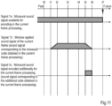
- each signal and algorithmic delay in encoding/decoding of the background art and a first embodiment will be described first, with reference to Figs. 7 to 11 schematically illustrating each signal when the frame length is 20 ms.
- the horizontal axis of each of Figs. 7 to 11 is a time axis. Since description will be made on an example where a current frame is processed at time t7 below, descriptions of "past" and “future” are attached to the left end and right end of the axis arranged at the top of each diagram, and an upward arrow is attached to the position of t7 which is the time when the current frame is processed.
- Figs. 7 schematically illustrating each signal when the frame length is 20 ms.
- the horizontal axis of each of Figs. 7 to 11 is a time axis. Since description will be made on an example where a current frame is processed at time t7 below, descriptions of "past" and "future” are attached to the left end and right end of the
- time of the start of each section is identified using words such as "from” or "at and after” in order to avoid a complicated wording expression
- the actual start of each section is the time immediately after the specified time
- the actual start of a digital signal for each section is the sample immediately after the specified time, as one skilled in the art could understand.
- Fig. 7 is a diagram schematically showing each signal in an encoding device of Non-Patent Literature 2 that processes the current frame at time t7. It is the signal 1a, which is a monaural sound signal up to t7, that the encoding device of Non-Patent Literature 2 can use for the processing of the current frame.
- the encoding device of Non-Patent Literature 2 uses the 8.75 ms section from t6 to t7 of the signal 1a for analysis, as a so-called "look-ahead section", and encodes the signal 1b, which is a signal obtained by applying a window to a part of the signal 1a for the 23.25 ms section from t1 to t6, to obtain and output a monaural code.
- the shape of the window is increasing in the 3.25 ms section from t1 to t2, is flat in the 16.75 ms section from t2 to t5 and is attenuating in the 3.25 ms section from t5 to t6.
- the signal 1b is a monaural sound signal corresponding to the monaural code obtained in the processing of the current frame.
- the encoding device of Non-Patent Literature 2 had already finished similar processing as processing of an immediately previous frame at the time when the monaural sound signal up to t3 was inputted, and had already encoded the signal 1c which is a signal obtained by applying a window in a shape of attenuating in the section from t1 to t2 to the monaural sound signal for the 23.25 ms section up to t2.
- the signal 1c is a monaural sound signal corresponding to a monaural code obtained in the processing of the immediately previous frame
- the section from t1 to t2 is an overlap section between the current frame and the immediately previous frame.
- the encoding device of Non-Patent Literature 2 encodes the signal 1d, which is a signal obtained by applying a window in a shape of increasing in the section from t5 to t6 to the monaural sound signal for the 23.25 ms section at and after t5, as processing of an immediately following frame. That is, the signal 1d is a monaural sound signal corresponding to a monaural code obtained in the processing of the immediately following frame, and the section from t5 to t6 is an overlap section between the current frame and the immediately following frame.
- Fig. 8 is a diagram schematically showing each signal in a decoding device of Non-Patent Literature 2 that processes the current frame at time t7 when the monaural code of the current frame is inputted from the encoding device of Non-Patent Literature 2.
- the decoding device of Non-Patent Literature 2 obtains the signal 2a which is a decoded sound signal for the section from t1 to t6, from the monaural code of the current frame.
- the signal 2a is a decoded sound signal corresponding to the signal 1b and is a signal to which the window in the shape of increasing in the section from t1 to t2, being flat in the section from t2 to t5 and attenuating in the section from t5 to t6 is applied.
- the decoding device of Non-Patent Literature 2 had already obtained the signal 2b which is a decoded sound signal of the 23.25 ms section up to t2, to which the window in the shape of attenuating in the section from t1 to t2 is applied, from the monaural code of the immediately previous frame at time t3 when the monaural code of the immediately previous frame was inputted, as the processing of the immediately previous frame.
- Non-Patent Literature 2 obtains the signal 2c which is a decoded sound signal of the 23.25 ms section at and after t5, to which the window in the shape of increasing in the section from t5 to t6 is applied, from a monaural code of the immediately following frame, as processing of the immediately following frame.
- the signal 2c since the signal 2c has not been obtained at time t7, a complete decoded sound signal is not obtained for the section from t5 to t6 at time t7 though an incomplete decoded sound signal is obtained.
- the decoding device of Non-Patent Literature 2 obtains and outputs the signal 2d, which is a monaural decoded sound signal of the 20 ms section from t1 to t5, by combining the signal 2b obtained in the processing of the immediately previous frame and the signal 2a obtained in the processing of the current frame for the section from t1 to t2 and using the signal 2a obtained in the processing of the current frame as it is for the section from t2 to t5.
- Non-Patent Literature 2 Since the decoding device of Non-Patent Literature 2 obtains the decoded sound signal, whose sections start from t1, at time t7, the algorithmic delay of the monaural encoding/decoding scheme of Non-Patent Literature 2 is 32 ms which is a time length from t1 to t7.
- Fig. 9 is a diagram schematically showing each signal in the decoding device 600 of Non-Patent Literature 1 in a case where the monaural decoding unit 610 uses the monaural decoding scheme of Non-Patent Literature 2.
- the stereo decoding unit 620 performs stereo decoding processing (upmix processing) of the current frame using the signal 3a, which is a monaural decoded sound signal up to t5 completely obtained by the monaural decoding unit 610.
- the stereo decoding unit 620 uses the signal 3b, which is a signal of the 23.25 ms section from t0 to t5 obtained by applying a window in a shape of increasing in the 3.25 ms section from t0 to t1, being flat in the 16.75 ms section from t1 to t4 and attenuating in the 3.25 ms section from t4 to t5 to the signal 3a to obtain the signal 3c-i ("i" is a channel number), which is a decoded sound signal from t0 to t5 to which a window in the same shape as the window for the signal 3b is applied, for each channel.
- the signal 3b is a signal of the 23.25 ms section from t0 to t5 obtained by applying a window in a shape of increasing in the 3.25 ms section from t0 to t1, being flat in the 16.75 ms section from t1 to t4 and attenuating in the 3.25 ms section from t
- the stereo decoding unit 620 had already obtained the signal 3d-i which is a decoded sound signal of each channel for the 23.25 ms section up to t1, to which a window in a shape of attenuating in the section from t0 to t1 is applied, at the point of time t3, as the processing of the immediately previous frame. Further, the stereo decoding unit 620 obtains the signal 3e-i which is a decoded sound signal of each channel for the 23.25 ms section at and after t4, to which the window in the shape of increasing in the section from t4 to t5 is applied, as the processing of the immediately following frame.
- the stereo decoding unit 620 obtains and outputs the signal 3f-i, which is a complete decoded sound signal for the 20 ms section from t0 to t4, by combining the signal 3d-i obtained in the processing of the immediately previous frame and the signal 3c-i obtained in the processing of the current frame for the section from t0 to t1 and using the signal 3c-i obtained in the processing of the current frame as it is for the section from t1 to t4.
- the algorithmic delay of the stereo encoding/decoding of Non-Patent Literature 1 using the monaural encoding/decoding scheme of Non-Patent Literature 2 as a monaural encoding/decoding scheme is 35.25 ms which is a time length from t0 to t7. That is, the algorithmic delay of the stereo encoding/decoding in the embedded encoding/decoding is larger than the algorithmic delay of the monaural encoding/decoding.
- Fig. 10 is a diagram schematically showing each signal in a decoding device 200 of the first embodiment described later.
- the decoding device 200 of the first embodiment has a configuration shown in Fig. 3 and includes a monaural decoding unit 210, an additional decoding unit 230 and a stereo decoding unit 220 that operate as described in detail in the first embodiment.
- the stereo decoding unit 220 processes the current frame using the signal 4c, which is a completely obtained monaural decoded sound signal up to t6.
- the signal 3a which is the monaural decoded sound signal up to t5 that is completely obtained by the monaural decoding unit 210 at time t7.
- the additional decoding unit 230 decodes an additional code CA to obtain the signal 4b, which is a monaural decoded sound signal of the 3.25 ms section from t5 to t6 (additional decoding processing), and the stereo decoding unit 220 performs stereo decoding processing (upmix processing) of the current frame using the signal 4c concatenating the signal 3a which is the monaural decoded sound signal up to t5 obtained by the monaural decoding unit 210, and the signal 4b which is the monaural decoded sound signal of the section from t5 to t6 obtained by the additional decoding unit 230.
- the stereo decoding unit 220 uses the signal 4d of the 23.75 ms section from t1 to t6 obtained by applying the window in the shape of increasing in the 3.25 ms section from t1 to t2, being flat in the 16.75 ms section from t2 to t5 and attenuating in the 3.25 ms section from t5 to t6 to the signal 4c to obtain the signal 4e-i, which is a decoded sound signal of the section from t1 to t6 to which a window in the same shape as the window for the signal 4d is applied, for each channel.
- the stereo decoding unit 220 had already obtained the signal 4f-i which is a decoded sound signal of each channel for the 23.75 ms section up to t2, to which the window in the shape of attenuating in the section from t1 to t2 is applied, at time t3, as the processing of the immediately previous frame. Further, the stereo decoding unit 220 obtains the signal 4g-i, which is a decoded sound signal of each channel for the 23.75 ms section at and after t5, to which the window in the shape of increasing in the section from t5 to t6 is applied, as processing of the immediately following frame.
- the stereo decoding unit 220 obtains and outputs the signal 4h-i, which is a complete decoded sound signal for the 20 ms section from t1 to t5, by combining the signal 4f-i obtained in the processing of the immediately previous frame and the signal 4e-i obtained in the processing of the current frame for the section from t1 to t2 and using the signal 4e-i obtained in the processing of the current frame as it is for the section from t2 to t5.
- the algorithmic delay of the stereo encoding/decoding in the embedded encoding/decoding of the first embodiment is 32 ms which is the time length from t1 to t7. That is, the algorithmic delay of the stereo encoding/decoding by the embedded encoding/decoding of the first embodiment is not larger than the algorithmic delay of the monaural encoding/decoding.
- Fig. 11 is a diagram schematically showing each signal in an encoding device 100 of the first embodiment described later, that is, an encoding device corresponding to the decoding device 200 of the first embodiment which is a decoding device for making each signal as schematically shown in Fig. 10 .
- the encoding device 100 of the first embodiment has a configuration shown in Fig.
- the 1 and includes an additional encoding unit 130 that processes encoding the signal 5c which is a part of the signal 1a, which is a monaural sound signal, for the section from t5 to t6, which is an overlap section between the current frame and the immediately following frame to obtain the additional code CA, in addition to a stereo encoding unit 110 that performs processing similar to that of the stereo encoding unit 510 of the encoding device 500 and a monaural encoding unit 120 that encodes the signal 1b, which is a signal obtained by applying a window to a part of the signal 1a, which is the monaural sound signal up to t7, for the section from t1 to t6 to obtain a monaural code CM similarly to the monaural encoding unit 520 of the encoding device 500.
- an additional encoding unit 130 that processes encoding the signal 5c which is a part of the signal 1a, which is a monaural sound signal, for the section from t5 to t6, which is
- section X is a section for which the monaural encoding unit 120 encodes a monaural sound signal to which a window is applied, in both of the processing of the current frame and processing of the immediately following frame.
- the section X is a section with a predetermined length of a sound signal that includes an end of the sound signal that the monaural encoding unit 120 encodes in the processing of the current frame, a section for which the monaural encoding unit 120 encodes a sound signal, to which the window in the attenuating shape is applied, in the processing of the current frame, a section with the predetermined length including the beginning of the section encoded by the monaural encoding unit 120 in the processing of the immediately following frame, and a section for which the monaural encoding unit 120 encodes a sound signal, to which the window in the increasing shape is applied, in the processing of the immediately following frame.
- the section X is a section for which the monaural decoding unit 210 decodes the monaural code CM to obtain a decoded sound signal to which a window is applied, in both of the processing of the current frame and the processing of the immediately following frame.
- the section X is a section with the predetermined length of a decoded sound signal that the monaural decoding unit 210 obtains by decoding the monaural code CM in the processing of the current frame, that includes the end of the decoded sound signal, a section of the decoded sound signal that the monaural decoding unit 210 obtains by decoding the monaural code CM in the processing of the current frame, to which a window in the attenuating shape is applied, a section with the predetermined length of a decoded sound signal that the monaural decoding unit 210 obtains by decoding the monaural code CM in the processing of the immediately following frame, that includes the start of the decoded sound signal, a section of the decoded sound signal that the monaural decoding unit 210 obtains by decoding the monaural code CM in the processing of the immediately following frame, to which a window in the increasing shape is applied, and a section for which the monaural decoding unit 210 obtains a decoded
- section t1 to t5 which is a section except the section X in a section for which monaural encoding/decoding is performed in the processing of the current frame
- section Y is, on the encoding side, a part of the section for which the monaural sound signal is encoded by the monaural encoding unit 120 in the processing of the current frame except the overlap section between the current frame and the immediately following frame
- the decoding side a part of the section for which the monaural code CM is decoded by the monaural decoding unit 210 to obtain a decoded sound signal in the processing of the current frame except the overlap section between the current frame and the immediately following frame.
- the section Y is a concatenation of a section where the monaural sound signal is represented by the monaural code CM of the current frame and the monaural code CM of the immediately previous frame and a section where a monaural sound signal is represented only by the monaural code CM of the current frame, the section Y is a section for which the monaural decoded sound signal can be completely obtained in processing up to the processing of the current frame.
- the encoding device 100 of the first embodiment includes the stereo encoding unit 110, the monaural encoding unit 120 and the additional encoding unit 130.
- the encoding device 100 encodes an inputted two-channel stereo time-domain sound signal (a two-channel stereo input sound signal) for each frame with a predetermined time length, for example, 20 ms to obtain and output a stereo code CS, a monaural code CM and an additional code CA described later.
- the two-channel stereo input sound signal inputted to the encoding device 100 is a digital voice or acoustic signal obtained, for example, by picking up sound such as voice and music by each of two microphones, and performing AD conversion thereof, and consists of an input sound signal of a left channel which is a first channel and an input sound signal of a right channel which is a second channel.
- Codes outputted by the encoding device 100 that is, the stereo code CS, the monaural code CM and the additional code CA are inputted to the decoding device 200 described later.
- the encoding device 100 processes steps S111, S121 and S131 illustrated in Fig. 2 for each frame, that is, each time the above-stated two-channel stereo input sound signal of the predetermined time length is inputted. In the case of the example described above, the encoding device 100 processes steps S111, S121 and S131 for the current frame when a two-channel stereo input sound signal of 20 ms from t3 to t7 is inputted.
- the stereo encoding unit 110 obtains and outputs the stereo code CS representing a characteristic parameter, which is a parameter representing a characteristic of difference between the inputted sound signals of the two channels, and a downmix signal which is a signal obtained by mixing the sound signals of the two channels (step S111).
- the stereo encoding unit 110 As an example of the stereo encoding unit 110, an operation of the stereo encoding unit 110 for each frame when taking information representing strength difference between the inputted sound signals of the two channels for each frequency band as the characteristic parameter will be described. Note that, though a specific example using a complex DFT (Discrete Fourier Transformation) is described below, a well-known method for conversion to the frequency domain other than the complex DFT may be used. Note that, in the case of converting such a sample sequence, whose number of samples is not a power of two, into the frequency domain, a well-known technology, such as using a sample sequence with zero stuffing so that the number of samples becomes a power of two, can be used.
- a well-known technology such as using a sample sequence with zero stuffing so that the number of samples becomes a power of two, can be used.
- the stereo encoding unit 110 performs complex DFT for each of the inputted sound signals of the two channels to obtain a complex DFT coefficient sequence (step S111-1).
- the complex DFT coefficient sequence is obtained by applying a window having overlap between frames and using processing in consideration of symmetry of complex numbers obtained by complex DFT.
- the processing is performed each time sound signals of the two channels, each of which has 640 samples corresponding to 20 ms, are inputted; and, for each channel, it is enough to obtain a sequence of 372 complex numbers corresponding to the former half of a sequence of 744 complex numbers to be obtained by performing complex DFT for a digital sound signal sample sequence of successive 744 samples (in the case of the example described above, a sample sequence of the section from t1 to t6) as the complex DFT coefficient sequence; which 744 samples includes 104 samples overlapping with a sample group at the end of the immediately previous frame (in case of the example described above, samples of the section from t1 to t2) and 104 samples overlapping with a sample group at the beginning of the immediately following frame (in the case of the example described above, samples of the section from t5 to t6) .
- each complex DFT coefficient of a complex DFT coefficient sequence of the first channel is indicated by V1(f); and each complex DFT coefficient of a complex DFT coefficient sequence of the second channel is indicated by V2(f).
- the stereo encoding unit 110 obtains sequences of radiuses of the complex DFT coefficients on the complex plane (step S111-2). The radius of each complex DFT coefficient of each channel on the complex plane corresponds to strength of the sound signal of each channel for each frequency bin.
- the stereo encoding unit 110 obtains an average of ratios of radiuses of one channel and radiuses of the other channel for each frequency band, and obtains a sequence of averages as the characteristic parameter (step S111-3).
- the sequence of averages is the characteristic parameter corresponding to the information representing the strength difference between the inputted sound signals of the two channels for each frequency band.
- the stereo encoding unit 110 obtain 93 values for each of four bands by dividing the radius V1r(f) of the first channel by the radius V2r(f) of the second channel, obtains averages thereof as Mr(1), Mr(2), Mr(3) and Mr(4), and obtains a series of average ⁇ Mr(1), Mr(2), Mr(3), Mr(4) ⁇ as the characteristic parameter.
- the number of bands is only required to be a value equal to or smaller than the number of frequency bins, and the same number as the number of frequency bins or 1 may be used as the number of bands.
- the stereo encoding unit 110 can obtain, for each frequency bin, a value of a ratio between a radius of one channel and a radius of the other channel and obtain a sequence of the obtained values of ratios as the characteristic parameter.
- the stereo encoding unit 110 can obtain, for each frequency bin, a value of a ratio between a radius of one channel and a radius of the other channel and obtain an average of the obtained ratio values for all the bands as the characteristic parameter.
- the number of frequency bins to be included in each frequency band is arbitrary.
- the number of frequency bins to be included in a low-frequency band may be smaller than the number of frequency bins to be included in a high-frequency band.
- the stereo encoding unit 110 may use difference between a radius of one channel and a radius of the other channel, instead of the ratio between a radius of one channel and a radius of the other channel. That is, in the case of the example described above, the stereo encoding unit 110 may use a value obtained by subtracting the radius V2r(f) of the second channel from the radius V1r(f) of the first channel, instead of the value obtained by dividing the radius V1r(f) of the first channel by the radius V2r(f) of the second channel.
- the stereo encoding unit 110 obtains the stereo code CS which is a code representing the characteristic parameter (step S111-4).
- the stereo code CS which is a code representing the characteristic parameter can be obtained by a well-known method.
- the stereo encoding unit 110 performs vector quantization of the value sequence obtained at step S111-3 to obtain a code, and outputs the obtained code as the stereo code CS.
- the stereo encoding unit 110 performs scalar quantization of each of the values included in the value sequence obtained at step S111-3 to obtain codes, and outputs the obtained codes together as the stereo code CS. Note that, in a case where what is obtained at step S111-3 is one value, the stereo encoding unit 110 can output a code obtained by scalar quantization of the one value, as the stereo code CS.
- the stereo encoding unit 110 also obtains a downmix signal which is a signal obtained by mixing the sound signals of the two channels of the first channel and the second channel (step S111-5). For example, in the processing of the current frame, the stereo encoding unit 110 obtains a downmix signal, which is a monaural signal obtained by mixing the sound signals of the two channels, for 20 ms from t3 to t7.
- the stereo encoding unit 110 may mix the sound signals of the two channels in the time domain like step S111-5A described later or may mix the sound signals of the two channels in the frequency domain like step S111-5B described later.
- the stereo encoding unit 110 obtains a sequence of averages of corresponding samples between the sample sequence of the sound signal of the first channel and the sample sequence of the sound signal of the second channel, as the downmix signal which is a monaural signal obtained by mixing the sound signals of the two channels (step S111-5A).
- the stereo encoding unit 110 obtains a complex DFT coefficient sequence applying complex DFT to the sample sequence of the first channel sound signal, obtains a complex DFT coefficient sequence applying complex DFT to the sample sequence of the second channel sound signal, obtains a radius average VMr(f) and an angle average VM ⁇ (f) from each complex DFT coefficient thereof, and obtains a sample sequence applying inverse complex DFT to a sequence of complex values VM(f) whose radius is VMr(f) and angle is VM ⁇ (f) on the complex plane , as the downmix signal which is a monaural signal obtained by mixing the sound signals of the two channels (step S111-5B).
- the encoding device 100 may be provided with a downmix unit 150 so that step S111-5 for obtaining a downmix signal may be processed not within the stereo encoding unit 110 but by the downmix unit 150.
- the stereo encoding unit 110 obtains and outputs the stereo code CS representing the characteristic parameter which is a parameter representing the characteristic of the difference between the inputted sound signals of the two channels, from the two-channel stereo input sound signal inputted to the encoding device 100 (step S111), and the downmix unit 150 obtains and outputs the downmix signal, which is a signal obtained by mixing the sound signals of the two channels, from the two-channel stereo input sound signal inputted to the encoding device 100 (step S151). That is, the stereo encoding unit 110 may perform steps S111-1 to step S111-4 described above as step S111, and the downmix unit 150 may perform step S111-5 described above as step S151.
- the downmix signal outputted by the stereo encoding unit 110 is inputted to the monaural encoding unit 120.
- the encoding device 100 is provided with the downmix unit 150, the downmix signal outputted by the downmix unit 150 is inputted to the monaural encoding unit 120.
- the monaural encoding unit 120 encodes the downmix signal by a predetermined encoding scheme to obtain and output the monaural code CM (step S121).
- a predetermined encoding scheme an encoding scheme that includes processing of applying a window having overlap between frames, for example, like the 13.2 kbps mode of the 3GPP EVS standard (3GPP TS26.445) of Non-Patent Literature 2 is used.
- the monaural encoding unit 120 encodes the signal 1b, which is a signal for the section from t1 to t6 obtained by applying a window in a shape of increasing in the section from t1 to t2 where the current frame and the immediately previous frame overlap, attenuating in the section from t5 to t6 where the current frame and the immediately following frame overlap and being flat in the section from t2 to t5 between the above sections, to the signal 1a which is the downmix signal, using the section from t6 to t7 of the signal 1a which is the "look-ahead section" for analysis processing, to obtain and output the monaural code CM.
- the signal 1b which is a signal for the section from t1 to t6 obtained by applying a window in a shape of increasing in the section from t1 to t2 where the current frame and the immediately previous frame overlap, attenuating in the section from t5 to t6 where the current frame and the immediately following frame overlap and being flat in the section from t
- the monaural encoding unit 120 when the encoding scheme used by the monaural encoding unit 120 includes processing of applying a window having overlap and analysis processing using a "look-ahead section", not only the downmix signal outputted by the stereo encoding unit 110 or the downmix unit 150 in the processing of the current frame but also a downmix signal outputted by the stereo encoding unit 110 or the downmix unit 150 in frame processing in the past is also used in encoding processing. Therefore, the monaural encoding unit 120 can be provided with a storage not shown to store downmix signals inputted in frame processing in the past so that the monaural encoding unit 120 can process encoding of the current frame using a downmix signal stored in the storage, too.
- the stereo encoding unit 110 or the downmix unit 150 may be provided with a storage not shown so that the stereo encoding unit 110 or the downmix unit 150 may output a downmix signal to be used by the monaural encoding unit 120 in encoding processing of the current frame, including a downmix signal obtained in frame processing in the past, in the processing of the current frame, and the monaural encoding unit 120 may use the downmix signals inputted from the stereo encoding unit 110 or the downmix unit 150 in the processing of the current frame.
- storing signals obtained in frame processing in the past in a storage not shown and using a signal in the processing of the current frame are also performed by each unit described later when necessary. Since it is well-known processing in the technological field of encoding, description thereof will be omitted below in order to avoid redundancy.
- the downmix signal outputted by the stereo encoding unit 110 is inputted to the additional encoding unit 130.
- the encoding device 100 is provided with the downmix unit 150
- the downmix signal outputted by the downmix unit 150 is inputted to the additional encoding unit 130.
- the additional encoding unit 130 encodes a part of the inputted downmix signal for the section X to obtain and output the additional code CA (step S131).
- the additional encoding unit 130 encodes the signal 5c, which is a downmix signal for the section from t5 to t6, to obtain and output the additional code CA.
- an encoding scheme such as well-known scalar quantization or vector quantization can be used.
- the decoding device 200 of the first embodiment includes the monaural decoding unit 210, the additional decoding unit 230 and the stereo decoding unit 220.
- the decoding device 200 decodes the inputted monaural code CM, additional code CA and stereo code CS to obtain and output the two-channel stereo time-domain sound signal (a two-channel stereo decoded sound signal).
- the codes inputted to the decoding device 200 that is, the monaural code CM, the additional code CA and the stereo code CS are outputted by the encoding device 100.
- the decoding device 200 processes steps S211, S221 and S231 illustrated in Fig.
- the decoding device 200 processes steps S211, S221 and S231 for the current frame. Note that, as shown by a broken line in Fig. 3 , the decoding device 200 also outputs a monaural decoded sound signal which is a monaural time-domain sound signal when necessary.
- the monaural code CM included among the codes inputted to the decoding device 200 is inputted to the monaural decoding unit 210.
- the monaural decoding unit 210 obtains and outputs the monaural decoded sound signal for the section Y using the inputted monaural code CM (step S211).
- a decoding scheme corresponding to the encoding scheme used by the monaural encoding unit 120 of the encoding device 100 is used.
- the monaural decoding unit 210 decodes the monaural code CM of the current frame by the predetermined decoding scheme to obtain the signal 2a for the 23.25 ms section from t1 to t6, to which the window in the shape of increasing in the 3.25 ms section from t1 to t2, being flat in the 16.75 ms section from t2 to t5 and attenuating in the 3.25 ms section from t5 to t6 is applied.
- the monaural decoding unit 210 obtains and outputs the signal 2d, which is the monaural decoded sound signal for 20 ms section from t1 to t5.
- the monaural decoding unit 210 stores the signal 2a for the section from t5 to t6 obtained from the monaural code CM of the current frame into a storage not shown in the monaural decoding unit 210.
- the additional code CA included among the codes inputted to the decoding device 200 is inputted to the additional decoding unit 230.
- the additional decoding unit 230 decodes the additional code CA to obtain and output an additional decoded signal which is the monaural decoded sound signal for the section X (step S231).
- a decoding scheme corresponding to the encoding scheme used by the additional encoding unit 130 is used.
- the additional decoding unit 230 decodes the additional code CA of the current frame to obtain and output the signal 4b which is the monaural decoded sound signal for the 3.25 ms section from t5 to t6.
- the monaural decoded sound signal outputted by the monaural decoding unit 210, the additional decoded signal outputted by the additional decoding unit 230 and the stereo code CS included among the codes inputted to the decoding device 200 are inputted to the stereo decoding unit 220.
- the stereo decoding unit 220 From the inputted monaural decoded sound signal, additional decoded signal and stereo code CS, the stereo decoding unit 220 obtains and outputs a stereo decoded sound signal, which is a decoded sound signal having the two channels (step S221).
- the stereo decoding unit 220 obtains a decoded downmix signal for a section Y+X which is a signal obtained by concatenating the monaural decoded sound signal for the section Y and the additional decoded signal for the section X (that is, a section obtained by concatenating the section Y and the section X) (step S221-1), and obtains and outputs the decoded sound signals of the two channels from the decoded downmix signal obtained at step S221-1 by upmix processing using the characteristic parameter obtained from the stereo code CS (step S221-2).
- the upmix processing is processing of obtaining the decoded sound signals of the two channels, regarding the decoded downmix signal as a signal obtained by mixing the decoded sound signals of the two channels and regarding the characteristic parameter obtained from the stereo code CS as information representing the characteristic of difference between the decoded sound signals of the two channels. The same goes for each embodiment described later.
- the stereo decoding unit 220 obtains the decoded downmix signal for the 23.25 ms section from t1 to t6 (the section from t1 to t6 of the signal 4c) by concatenating the monaural decoded sound signal for the 20 ms section from t1 to t5 outputted by the monaural decoding unit 210 (the section from t1 to t5 of the signals 2d and 3a) and an additional decoded signal (the signal 4b) for the 3.25 ms section from t5 to t6 outputted by the additional decoding unit 230.
- the stereo decoding unit 220 obtains and outputs the decoded sound signals of the two channels for the 20 ms section from t1 to t5 (signals 4h-1 and 4h-2).
- Step S221-2 performed by the stereo decoding unit 220 when the characteristic parameter is information representing the strength difference between the sound signals of the two channels for each frequency band will be described as an example of step S221-2 performed by the stereo decoding unit 220.
- the stereo decoding unit 220 decodes the inputted stereo code CS to obtain the information representing the strength difference for each frequency band (S221-21).
- the stereo decoding unit 220 obtains the characteristic parameter from the stereo code CS by a scheme corresponding to the scheme by which the stereo encoding unit 110 of the encoding device 100 obtained the stereo code CS from the information representing the strength difference for each frequency band.
- the stereo decoding unit 220 performs vector decoding of the inputted stereo code CS to obtain element values of a vector corresponding to the inputted stereo code CS as information representing strength differences for a plurality of frequency bands, respectively.
- the stereo decoding unit 220 performs scalar decoding of each of codes included in the inputted stereo code CS to obtain the information representing the strength difference for each frequency band. Note that, in a case where the number of bands is one, the stereo decoding unit 220 performs scalar decoding of the inputted stereo code CS to obtain information representing the strength difference for the one frequency band, that is, for the whole band.
- the stereo decoding unit 220 obtains and outputs the decoded sound signals of the two channels from the decoded downmix signal obtained at step S221-1 and the characteristic parameter obtained at step S221-21 (step S220-22).
- the stereo decoding unit 220 operates at step S221-22 as follows.
- the stereo decoding unit 220 obtains the signal 4d obtained by applying the window in the shape of increasing in the 3.25 ms section from t1 to t2, being flat in the 16.75 ms section from t2 to t5 and attenuating in the 3.25 ms section from t5 to t6 to a decoded downmix signal with 744 samples for the 23.25 ms section from t1 to t6 (step S221-221).
- the stereo decoding unit 220 obtains a sequence of 372 complex numbers of the former half of a sequence of 744 complex numbers to be obtained by performing complex DFT to the signal 4d as a complex DFT coefficient sequence (a monaural complex DFT coefficient sequence) (step S221-222).
- each complex DFT coefficient of the monaural complex DFT coefficient sequence obtained by the stereo decoding unit 220 is indicated by MQ(f).
- the stereo decoding unit 220 obtains a radius MQr(f) of each complex DFT coefficient on the complex plane and an angle MQ ⁇ (f) of each complex DFT coefficient on the complex plane from the monaural complex DFT coefficient sequence (step S221-223).
- the stereo decoding unit 220 obtains a value by multiplying each radius MQr(f) by a square root of a corresponding value in the characteristic parameter, as each radius VLQr(f) of the first channel, and obtains a value by dividing each radius MQr(f) by a square root of a corresponding value in the characteristic parameter, as each radius VRQr(f) of the second channel (step S221-224).
- the corresponding value in the characteristic parameter for each frequency bin is Mr(1) when "f" is 1 to 93, Mr(2) when "f” is 94 to 186, Mr(3) when "f” is 187 to 279 and Mr(4) when "f” is 280 to 372.
- the stereo decoding unit 220 can obtain a value by adding a value obtained by dividing a corresponding value in the characteristic parameter by 2 to each radius MQr(f) as each radius VLQr(f) of the first channel and obtain a value by subtracting the value obtained by dividing a corresponding value in the characteristic parameter by 2 from each radius MQr(f) as each radius VRQr(f) of the second channel.
- the stereo decoding unit 220 performs inverse complex DFT to the sequence of such complex numbers that the radius and angle on the complex plane are VLQr(f) and MQ ⁇ (f), respectively, to obtain a decoded sound signal of the first channel with the 744 samples for the 23.25 ms section from t1 to t6 (the signal 4e-1) to which a window is applied, and performs inverse complex DFT to the sequence of such complex numbers that the radius and angle on the complex plane are VRQr(f) and MQ ⁇ (f), respectively, to obtain a decoded sound signal of the second channel with the 744 samples for the 23.25 ms section from t1 to t6 (the signal 4e-2) (step S221-225) to which a window is applied.
- the decoded sound signals of the channels to which the window is applied obtained at step S221-225 are signals to which the window in the shape of increasing in the 3.25 ms section from t1 to t2, being flat in the 16.75 ms section from t2 to t5 and attenuating in the 3.25 ms section from t5 to t6 is applied.
- the stereo decoding unit 220 obtains and outputs the decoded sound signals for the 20 ms section from t1 to t5 (the signal 4h-1 and 4h-2) by combining the signals obtained at step S221-225 for the immediately previous frame (the signal 4f-1 and 4f-2) and the signals obtained at step S221-225 for the current frame (the signals 4e-1 and 4e-2) for the section from t1 to t2, respectively, and using the signals obtained at step S221-225 (the signals 4e-1 and 4e-2) for the current frame as they are for the section from t2 to t5, for the first and second channels, respectively (step S221-226).
- Difference between the downmix signal and a locally decoded signal of monaural encoding for the section Y which is a time section for which the monaural decoding unit 210 can obtain a complete monaural decoded sound signal from the monaural code CM, may also be an encoding target of the additional encoding unit 130.
- This embodiment is regarded as a second embodiment, and points different from the first embodiment will be described.
- the monaural encoding unit 120 In addition to encoding the downmix signal by the predetermined encoding scheme to obtain and output the monaural code CM, the monaural encoding unit 120 also obtains and outputs a signal obtained by decoding the monaural code CM, that is, a monaural locally decoded signal which is a locally decoded signal of the downmix signal for the section Y (step S122).
- the monaural encoding unit 120 obtains a locally decoded signal corresponding to the monaural code CM of the current frame, that is, a locally decoded signal to which the window in the shape of increasing in the 3.25 ms section from t1 to t2, being flat in the 16.75 ms section from t2 to t5 and attenuating in the 3.25 ms section from t5 to t6 is applied.
- the monaural encoding unit 120 obtains and outputs a locally decoded signal for the 20 ms section from t1 to t5.
- a signal stored in the storage not shown in the monaural encoding unit 120 is used as the locally decoded signal corresponding to the monaural code CM of the immediately previous frame for the section from t1 to t2.
- the monaural encoding unit 120 Since a part of the locally decoded signal corresponding to the monaural code CM of the current frame for the section from t5 to t6 is used as "a locally decoded signal corresponding to the monaural code CM of an immediately previous frame" in the processing of the immediately following frame, the monaural encoding unit 120 stores the locally decoded signal for the section from t5 to t6 obtained from the monaural code CM of the current frame into the storage not shown in the monaural encoding unit 120.
- the monaural locally decoded signal outputted by the monaural encoding unit 120 is also inputted to the additional encoding unit 130 as shown by a dashed line in Fig. 1 .
- the additional encoding unit 130 encodes not only the downmix signal for the section X which is the encoding target of the additional encoding unit 130 of the first embodiment, but also a difference signal between the downmix signal and the monaural locally decoded signal for the section Y (a signal configured by subtraction between sample values of corresponding samples) to obtain and output the additional code CA (step S132).
- the additional encoding unit 130 can encode each of the downmix signal for the section X and the difference signal for the section Y to obtain codes and obtain a concatenation of the obtained codes as the additional code CA.
- an encoding scheme similar to that of the additional encoding unit 130 of the first embodiment can be used.
- the additional encoding unit 130 may encode a signal obtained by concatenating the difference signal for the section Y and the downmix signal for the section X to obtain the addition code CA.
- the additional encoding unit 130 can perform first additional encoding that encodes the downmix signal for the section X to obtain a code (a first additional code CA1) and second additional encoding that encodes a signal obtained by concatenating the difference signal for the section Y (that is, a quantization error signal of the monaural encoding unit 120) and a difference signal between the downmix signal for the section X and the locally decoded signal of the first additional encoding (that is, a quantization error signal of the first additional encoding) to obtain a code (a second additional code CA2), and obtain a combination of the first additional code CA1 and the second additional code CA2 as the additional code CA.
- a first additional code CA1 that encodes the downmix signal for the section X
- second additional encoding that encodes a signal obtained by concatenating the difference signal for the section Y (that is, a quantization error signal of the monaural encoding unit 120) and a difference signal between the downmix signal for the section X
- the second additional encoding is performed, with a concatenation of such signals that amplitude difference between two sections is assumed to be smaller than that between the difference signal for the section Y and the downmix signal for the section X as an encoding target, and, as for the downmix signal itself, the first additional encoding is performed, with only a short time section as an encoding target. Therefore, efficient encoding can be expected.
- the additional encoding unit 130 encodes the inputted downmix signal for the section X to obtain the first additional code CA1 (step S132-1; hereinafter also referred to as "first additional encoding") and obtains a locally decoded signal for the section X corresponding to the first additional code CA1, that is, a locally decoded signal of the first encoding for the section X (step S132-2).
- first additional encoding an encoding scheme such as well-known scalar quantization or vector quantization can be used.
- the additional encoding unit 130 obtains a difference signal (a signal configured by subtraction between sample values of corresponding samples) between the inputted downmix signal for the section X and the locally decoded signal for the section X obtained at step S132-2 (step S132-3). Further, the additional encoding unit 130 obtains a difference signal (a signal configured by subtraction between sample values of corresponding samples) between the downmix signal and the monaural locally decoded signal for the section Y (step S132-4).
- a difference signal a signal configured by subtraction between sample values of corresponding samples
- the additional encoding unit 130 encodes a signal obtained by concatenating the difference signal for the section Y obtained at step S132-4 and the difference signal for the section X obtained at step S132-3 to obtain the second additional code CA2 (step S132-5; hereinafter also referred to as "second additional encoding").
- second additional encoding an encoding scheme of collectively encoding a sample sequence obtained by concatenating a sample sequence of the difference signal for the section Y obtained at step S132-4 and a sample sequence of the difference signal for the section X obtained at step S132-3, for example, an encoding scheme using prediction in the time domain or an encoding scheme adapted to amplitude imbalance in the frequency domain is used.
- the additional encoding unit 130 outputs a concatenation of the first additional code CA1 obtained at step S132-1 and the second additional code CA2 obtained at step S132-5 as the additional code CA (step S132-6).
- the additional encoding unit 130 may target a weighted difference signal for encoding instead of the difference signal described above. That is, the additional encoding unit 130 may code a weighted difference signal (a signal configured by weighted subtraction between sample values of corresponding samples) between the downmix signal and the monaural locally decoded signal for the section Y and the downmix signal for the section X to obtain and output the additional code CA.
- the additional encoding unit 130 can obtain the weighted difference signal (a signal configured by weighted subtraction between sample values of corresponding samples) between the downmix signal and the monaural locally decoded signal for the section Y as the processing of step S132-4.
- the additional encoding unit 130 may obtain the weighted difference signal (a signal configured by weighted subtraction between sample values of corresponding samples) between the inputted downmix signal for the section X and the locally decoded signal for the section X obtained at step S132-2 as the processing of step S132-3 of [Specific example 1 of additional encoding unit 130].
- the weight used for generation of each weighted difference signal can be encoded by a well-known encoding technology to obtain a code, and the obtained code (a code representing the weight) can be included in the additional code CA.
- the additional decoding unit 230 decodes the additional code CA to obtain and output not only the additional decoded signal for the section X, which is an additional decoded signal obtained by the additional decoding unit 230 of the first embodiment but also an additional decoded signal for the section Y (step S232).
- a decoding scheme corresponding to the encoding scheme used by the additional encoding unit 130 at step S132 is used. That is, if the additional encoding unit 130 uses [Specific example 1 of additional encoding unit 130] at step S132, the additional decoding unit 230 performs the processing of [Specific example 1 of additional decoding unit 230] described below.
- the additional decoding unit 230 decodes the first additional code CA1 included in the additional code CA to obtain a first decoded signal for the section X (step S232-1; hereinafter also referred to as "first additional decoding").
- first additional decoding a decoding scheme corresponding to the encoding scheme used for the first additional encoding by the additional encoding unit 130 is used.
- second additional decoding a decoding scheme corresponding to the encoding scheme used for the first additional encoding by the additional encoding unit 130 is used.
- the additional decoding unit 230 decodes the second additional code CA2 included in the additional code CA to obtain a second decoded signal for the sections Y and X (step S232-2; hereinafter also referred to as "second additional decoding").
- a decoding scheme corresponding to the encoding scheme used by the additional encoding unit 130 for the second additional encoding is used, that is, a decoding scheme that yields, from the code, a collective sample sequence which is a concatenation of a sample sequence of the additional decoded signal for the section Y and a sample sequence of the second decoded signal for the section X; for example, a decoding scheme using prediction in the time domain or a decoding scheme adapted to amplitude imbalance in the frequency domain.
- the additional decoding unit 230 obtains a part of the second decoded signal obtained at step S232-2 for the section Y as the additional decoded signal for the section Y, obtains an addition signal (a signal configured by addition of sample values of corresponding samples) of the first decoded signal for the section X obtained at step S232-1 and a part of the second decoded signal for the section X obtained at step S232-2 as the additional decoded signal for the section X, and outputs the additional decoded signals for the sections Y and X (step S232-4).
- an addition signal a signal configured by addition of sample values of corresponding samples
- the additional decoding unit 230 can decode a code of the additional code CA except the code representing the weight to obtain and output an additional decoded signal, and decode the code representing the weight, which is included in the additional code CA, to obtain and output the weight at step S232 described above.
- a code representing a weight for the section X, which is included in the additional code CA, is decoded to obtain the weight for the section X; and, at step S232-4, the additional decoding unit 230 can obtain the part of the second decoded signal obtained at step S232-2 for the section Y as the additional decoded signal for the section Y, obtain a weighted addition signal (a signal configured by weighted addition of sample values of corresponding samples) of the first decoded signal for the section X obtained at step S232-1 and the part of the second decoded signal obtained at step S232-2 for the section X as the additional decoded signal for the section X, and output the additional decoded signals for the sections Y and X and a weight for the section Y obtained by decoding a code representing the weight for the section Y, which is included in the additional code CA.
- the stereo decoding unit 220 performs steps S222-1 and S222-2 below (step S222).
- the stereo decoding unit 220 obtains a signal concatenating a sum signal (a signal configured by addition of sample values of corresponding samples) of the monaural decoded sound signal for the section Y and the additional decoded signal for the section Y and the additional decoded signal for the section X, as a decoded downmix signal for the section Y+X (step S222-1) instead of step S221-1 performed by the stereo decoding unit 220 of the first embodiment and obtains and outputs the decoded sound signals of the two channels from the decoded downmix signal obtained at step S222-1 by the upmix processing using the characteristic parameter obtained from the stereo code CS, using the decoded downmix signal obtained at step S222-1 instead of the decoded downmix signal obtained at step S221-1 (step S222-2).
- the stereo decoding unit 220 can obtain a signal concatenating a weighted sum signal (a signal configured by weighted addition of sample values of corresponding samples) of the monaural decoded sound signal for the section Y and the additional decoded signal for the section Y and the additional decoded signal for the section X, as the decoded downmix signal for the section X+Y at step S222-1.
- a weighted sum signal a signal configured by weighted addition of sample values of corresponding samples
- the weight for the section Y outputted by the additional decoding unit 230 can be used. Though the above is the same for addition of signals in each embodiment described later, it is well known in the technological field of encoding that weighted addition (generation of a weighted sum signal) is performed instead of addition (generation of a sum signal) and that, in that case, a weight is also obtained from a code as described in the description of the additional decoding unit 230.
- the algorithmic delay of stereo encoding/decoding is not larger than the algorithmic delay of monaural encoding/decoding, it is possible to cause the quality of a decoded downmix signal used for stereo decoding to be higher than the first embodiment. Therefore, it is possible to cause the sound quality of a decoded sound signal of each channel obtained by stereo decoding to be high.
- the monaural encoding processing by the monaural encoding unit 120 and the additional encoding processing by the additional encoding unit 130 are used as encoding processing for high-quality encoding of a downmix signal; the monaural code CM and the additional code CA are obtained as codes that represents the favorable downmix signal; and the monaural decoding processing by the monaural decoding unit 210 and the additional decoding processing by the additional decoding unit 230 are used as decoding processing for obtaining a high-quality decoded downmix signal.
- a code amount assigned to each of the monaural code CM and the additional code CA can be arbitrarily determined according to purposes.
- a larger code amount can be assigned to the additional code CA. That is, "monaural code” and “additional code” are mere convenient names from a viewpoint of stereo encoding/decoding. Since each of the monaural code CM and the additional code CA is a part of a code representing a downmix signal, one of the codes may be called “a first downmix code”, and the other may be called “a second downmix code”. When it is assumed that a larger code amount is assigned to the additional code CA, the additional code CA may be called “a downmix code", "a downmix signal code” or the like. The above is the same in a third embodiment and each embodiment based on the second embodiment described after the third embodiment.
- the stereo decoding unit 220 may obtain the decoded sound signals of the two channels with a higher sound quality by using a decoded downmix signal corresponding to a downmix signal obtained by mixing sound signals of the two channels in the frequency domain, and it is possible for the monaural decoding unit 210 to obtain a monaural decoded sound signal with a higher sound quality when the monaural encoding unit 120 encodes a signal obtained by mixing sound signals of the two channels in the time domain.
- the stereo encoding unit 110 obtains the downmix signal by mixing the sound signals of the two channels inputted to the encoding device 100 in the frequency domain, that the monaural encoding unit 120 encodes a signal obtained by mixing the sound signals of the two channels inputted to the encoding device 100 in the time domain, and that the additional encoding unit 130 also encodes difference between the signal obtained by mixing the sound signals of the two channels in the frequency domain and the signal obtained by mixing the sound signals of the two channels in the time domain.
- This embodiment is regarded as a third embodiment, and points different from the second embodiment will be mainly described.
- the stereo encoding unit 110 operates as described in the first embodiment similarly to the stereo encoding unit 110 of the second embodiment. However, as for the processing of obtaining the downmix signal which is the signal obtained by mixing the sound signals of the two channels, the processing is performed by processing of mixing the sound signals of the two channels in the frequency domain, for example, like step S111-5B (step S113). That is, the stereo encoding unit 110 obtains a downmix signal obtained by mixing the sound signals of the two channels in the frequency domain. For example, in the processing of the current frame, the stereo encoding unit 110 can obtain a downmix signal, which is a monaural signal obtained by mixing the sound signals of the two channels in the frequency domain, for the section from t1 to t6.
- the stereo encoding unit 110 obtains and outputs the stereo code CS representing the characteristic parameter, which is a parameter representing the characteristic of the difference between the sound signals of the two channels inputted from the two-channel stereo input sound signal inputted to the encoding device 100 (step S113), and the downmix unit 150 obtains and outputs the downmix signal, which is a signal obtained by mixing the sound signals of the two channels in the frequency domain, from the two-channel stereo input sound signal inputted to the encoding device 100 (step S153).
- the encoding device 100 of the third embodiment also includes a monaural encoding target signal generation unit 140 as shown by a one-dot chain line in Fig. 1 .
- the two-channel stereo input sound signal inputted to the encoding device 100 is inputted to the monaural encoding target signal generation unit 140.
- the monaural encoding target signal generation unit 140 obtains a monaural encoding target signal, which is a monaural signal, from the inputted two-channel stereo input sound signal by processing of mixing the sound signals of the two channels in the time domain (step S143).
- the monaural encoding target signal generation unit 140 obtains a sequence of averages of corresponding samples between the sample sequence of the sound signal of the first channel and the sample sequence of the sound signal of the second channel, as the monaural encoding target signal which is a signal obtained by mixing the sound signals of the two channels. That is, the monaural encoding target signal obtained by the monaural encoding target signal generation unit 140 is a signal obtained by mixing the sound signals of the two channels in the time domain.
- the monaural encoding target signal generation unit 140 can obtain the monaural encoding target signal, which is the monaural signal obtained by mixing the sound signals of the two channels in the time domain, for 20 ms from t3 to t7.
- the monaural encoding target signal outputted by the monaural encoding target signal generation unit 140 is inputted to the monaural encoding unit 120 instead of the downmix signal outputted by the stereo encoding unit 110 or the downmix unit 150.
- the monaural encoding unit 120 encodes the monaural encoding target signal to obtain and output the monaural code CM (step S123).
- the monaural encoding unit 120 encodes the signal for the section from t1 to t6 obtained by applying the window in the shape of increasing in the section from t1 to t2 where the current frame and the immediately previous frame overlap, attenuating in the section from t5 to t6 where the current frame and the immediately following frame overlap and being flat in the section from t2 to t5 between the above sections, to the monaural encoding target signal, using the section from t6 to t7 of the monaural encoding target signal which is "a look-ahead section" for analysis processing, to obtain and output the monaural code CM.
- the additional encoding unit 130 encodes a difference signal or weighted difference signal (a signal configured by subtraction or weighted subtraction between sample values of corresponding samples) between the downmix signal and the monaural locally decoded signal for the section Y and the downmix signal for the section X to obtain and output the additional code CA (step S133).
- the downmix signal for the section Y is a signal obtained by mixing the sound signals of the two channels in the frequency domain
- the monaural locally decoded signal for the section Y is a signal obtained by locally decoding a signal obtained by mixing the sound signals of the two channels in the time domain.
- the additional encoding unit 130 of the third embodiment can perform the first additional encoding that encodes the downmix signal for the section X to obtain a first additional code CA and the second additional encoding that encodes a signal obtained by concatenating the difference signal or weighted difference signal for the section Y and the difference signal or weighted difference signal between the downmix signal for the section X and the locally decoded signal of the first additional encoding to obtain a second additional code CA2, and obtain a concatenation of the first additional code CA1 and the second additional code CA2 as the additional code CA, as described in [Specific example 1 of additional encoding unit 130].
- the monaural decoding unit 210 obtains and outputs the monaural decoded sound signal for the section Y using the monaural code CM (step S213).
- the monaural decoded sound signal obtained by the monaural decoding unit 120 of the third embodiment is a decoded signal of a signal obtained by mixing sound signals of the two channels in the time domain.
- the additional decoding unit 230 decodes the additional code CA to obtain and output additional decoded signals for the sections Y and X, (step S233).
- the additional decoded signal for the section Y includes difference between a signal obtained by mixing sound signals of the two channels in the time domain and the monaural decoded sound signal, and difference between a signal obtained by mixing the sound signals of the two channels in the frequency domain and the signal obtained by mixing the sound signals of the two channels in the time domain.
- the stereo decoding unit 220 performs steps S223-1 and S223-2 below (step S223). Similarly to the additional decoding unit 230 of the second embodiment, the stereo decoding unit 220 obtains a signal obtained by concatenating a sum signal or weighted sum signal (a signal configured by addition or weighted addition of sample values of corresponding samples) of the monaural decoded sound signal for the section Y and an additional decoded signal for the section Y and an additional decoded signal for the section X, as the decoded downmix signal for the section Y+X (step S223-1), and obtains and outputs the decoded sound signals of the two channels from the decoded downmix signal obtained at step S223-1 by the upmix processing using the characteristic parameter obtained from the stereo code CS (step S223-2).
- a sum signal or weighted sum signal a signal configured by addition or weighted addition of sample values of corresponding samples
- the sum signal for the section Y includes the monaural decoded sound signal obtained by performing monaural encoding/decoding of the signal obtained by mixing the sound signals of the two channels in the time domain, difference between the signal obtained by mixing the sound signals of the two channels in the time domain and the monaural decoded sound signal, and difference between the signal obtained by mixing the sound signals of the two channels in the frequency domain and the signal obtained by mixing the sound signals of the two channels in the time domain.
- each of the first to third embodiments may be changed so that, as for the section X, the additional encoding unit 130 encodes not the downmix signal itself but difference between the downmix signal and a monaural locally decoded signal obtained from the signal of the frames up to the current frame.
- This embodiment will be described as fourth embodiments.
- the downmix signal outputted by the stereo encoding unit 110 or the downmix unit 150 is inputted to the monaural encoding unit 120.
- the monaural encoding unit 120 obtains and outputs the monaural code CM obtained by encoding the downmix signal, and a signal obtained by decoding the monaural code CM of the frames up to the current frame, that is, a monaural locally decoded signal, which is a locally decoded signal of the downmix signal for the section Y+X (step S124).
- the monaural encoding unit 120 obtains a locally decoded signal corresponding to the monaural code CM of the current frame, that is, a locally decoded signal to which the window in the shape of increasing in the 3.25 ms section from t1 to t2, being flat in the 16.75 ms section from t2 to t5 and attenuating in the 3.25 ms section from t5 to t6 is applied; and, by combining a locally decoded signal corresponding to the monaural code CM of the immediately previous frame and the locally decoded signal corresponding to the monaural code CM of the current frame, for the section from t1 to t2, and using the locally decoded signal corresponding to the monaural code CM of the current frame as it is, for the section from t2 to t6, the monaural encoding unit 120 obtains and outputs a locally decoded signal for the section of 23.25
- a locally decoded signal for the section from t5 to t6 is a locally decoded signal that becomes a complete locally decoded signal by being combined with a locally decoded signal to which the window in the increasing shape is applied, the locally decoded signal being obtained in processing of the immediately following frame, and is an incomplete locally decoded signal to which the window in the attenuating shape is applied.
- the downmix signal outputted by the stereo encoding unit 110 or the downmix unit 150, and the monaural locally decoded signal outputted by the monaural encoding unit 120 are inputted to the additional encoding unit 130.
- the additional encoding unit 130 encodes a difference signal or weighted difference signal (a signal configured by subtraction or weighted subtraction between sample values of corresponding samples) between the downmix signal and the monaural locally decoded signal for the section Y+X to obtain and output the additional code CA (step S134).
- the monaural code CM is inputted to the monaural decoding unit 210.
- the monaural decoding unit 210 obtains and outputs the monaural decoded sound signal for the section Y+X using the monaural code CM (step S214).
- the decoded signal for the section X that is, the section from t5 to t6 is a decoded signal that becomes a complete decoded signal by being combined with a decoded signal to which the window in the increasing shape is applied, the decoded signal being obtained in processing of the immediately following frame, and is an incomplete decoded signal to which the window in the attenuating shape is applied.
- the additional code CA is inputted to the additional decoding unit 230.
- the additional decoding unit 230 decodes the additional code CA to obtain and output an additional decoded signal for the section Y+X (step S234).
- the monaural decoded sound signal outputted by the monaural decoding unit 210, the additional decoded signal outputted by the additional decoding unit 230 and the stereo code CS inputted to the decoding device 200 are inputted to the stereo decoding unit 220.
- the stereo decoding unit 220 obtains a sum signal or weighted sum signal (a signal configured by addition or weighted addition of sample values of corresponding samples) of the monaural decoded sound signal and the additional decoded signal for the section Y+X as the decoded downmix signal, and obtains and outputs the decoded sound signals of the two channels from the decoded downmix signal by the upmix processing using the characteristic parameter obtained from the stereo code CS (step S224).
- a sum signal or weighted sum signal a signal configured by addition or weighted addition of sample values of corresponding samples
- each of the monaural locally decoded signal obtained by the monaural encoding unit 120, the difference signal or weighted difference signal coded by the additional encoding unit 130 and the additional decoded signal obtained by the additional decoding unit 230 in the description of the fourth embodiment A is the signal for the section X
- the stereo decoding unit 220 obtains a signal that is a concatenation of the monaural decoded sound signal for the section Y and a sum signal or weighted sum signal of the monaural decoded sound signal and the additional decoded signal for the section X as the decoded downmix signal
- a fourth embodiment C which is a fourth embodiment obtained by changing the first embodiment, is obtained.
- the downmix signal for the section X includes a part that can be predicted from the monaural locally decoded signal for the section Y. Therefore, for the section X, the difference between the downmix signal and a predicted signal from the monaural locally decoded signal for the section Y may be encoded by the additional encoding unit 130 in each of the first to fourth embodiments. This embodiment will be described as fifth embodiments.
- the additional encoding unit 130 performs steps S135A-1 and S135A-2 below (step S135A).
- the additional encoding unit 130 obtains a predicted signal for the monaural locally decoded signal for the section X from the inputted monaural locally decoded signal for the section Y or the section Y+X (however, for the section X, an incomplete monaural locally decoded signal as described above) using a predetermined well-known prediction technology (step S135A-1).
- the inputted incomplete monaural locally decoded signal for the section X is included in the predicted signal for the section X.
- the additional encoding unit 130 encodes the difference signal or weighted difference signal (a signal configured by subtraction or weighted subtraction between sample values of corresponding samples) between the downmix signal and the monaural locally decoded signal for the section Y and a difference signal or weighted difference signal (a signal configured by subtraction or weighted subtraction between sample values of corresponding samples) between the downmix signal for the section X and the predicted signal obtained at step S135A-1 to obtain and output the additional code CA (step S135A-2).
- a signal obtained by concatenating the difference signal for the section Y and the difference signal for the section X may be encoded to obtain the additional code CA.
- each of the difference signal for the section Y and the difference signal for the section X may be encoded to obtain a code, and a concatenation of the obtained codes may be obtained as the additional code CA.
- an encoding scheme similar to that of the additional encoding unit 130 of each of the second embodiment, the third embodiment, the fourth embodiment A and the fourth embodiment B can be used.
- the stereo decoding unit 220 performs steps S225A-0 to S225A-2 below (step S225A). First, the stereo decoding unit 220 obtains the predicted signal for the section X from the monaural decoded sound signal for the section Y or the section Y+X, using the same prediction technology used by the additional encoding unit 130 at step S135 (step S225A-0).
- the stereo decoding unit 220 obtains a signal obtained by concatenating a sum signal or weighted sum signal (a signal configured by addition or weighted addition of sample values of corresponding samples) of the monaural decoded sound signal and the additional decoded signal for the section Y and a sum signal or weighted sum signal (a signal configured by addition or weighted addition of sample values of corresponding samples) of the additional decoded signal and the predicted signal for the section X as the decoded downmix signal for the section Y+X (step S225A-1).
- the stereo decoding unit 220 obtains and outputs the decoded sound signals of the two channels from the decoded downmix signal obtained at step S225A-1, by the upmix processing using the characteristic parameter obtained from the stereo code CS (step S225A-2).
- the monaural encoding unit 120 In addition to the monaural code CM obtained by encoding the downmix signal, the monaural encoding unit 120 also obtains and outputs, for the section Y or the section Y+X, a signal obtained by decoding the monaural code CM of the frames up to the current frame, that is, a monaural locally decoded signal which is a locally decoded signal of the inputted downmix signal (step S125B).
- the monaural locally decoded signal for the section X is an incomplete monaural locally decoded signal.
- the additional encoding unit 130 performs steps S135B-1 and S135B-2 below (step S135B).
- the additional encoding unit 130 obtains the predicted signal for the monaural locally decoded signal for the section X from the inputted monaural locally decoded signal for the section Y or the section Y+X (however, for the section X, an incomplete monaural locally decoded signal as described above) using the predetermined well-known prediction technology (step S135B-1).
- the inputted monaural locally decoded signal for the section X is included in the predicted signal for the section X.
- the additional encoding unit 130 encodes the difference signal or weighted difference signal between the downmix signal for the section X and the predicted signal (a signal configured by subtraction or weighted subtraction between sample values of corresponding samples) obtained at step S135B-1 to obtain and output the additional code CA (step S135B-2).
- the encoding for example, an encoding scheme similar to that of the additional encoding unit 130 of each of the first embodiment and the fourth embodiment C can be used.
- the stereo decoding unit 220 performs steps S225B-0 to S225B-2 below (step S225B). First, the stereo decoding unit 220 obtains the predicted signal for the section X from the monaural decoded sound signal for the section Y or the section Y+X, using the same prediction technology used by the additional encoding unit 130 (step S225B-0).
- the stereo decoding unit 220 obtains a signal that is a concatenation of the monaural decoded sound signal for the section Y and a sum signal or weighted sum signal (a signal configured by addition or weighted addition of sample values of corresponding samples) of the additional decoded signal and the predicted signal for the section X as the decoded downmix signal for the section Y+X (step S225B-1).
- the stereo decoding unit 220 obtains and outputs the decoded sound signals of the two channels from the decoded downmix signal obtained at step S225B-1, by the upmix processing using the characteristic parameter obtained from the stereo code CS (step S225B-2).
- the decoded downmix signal for the section X used by the stereo decoding unit 220 is obtained at least by decoding the additional code CA.
- a predicted signal from the monaural decoded sound signal for the section Y may be used as the decoded downmix signal for the section X used by the stereo decoding unit 220.
- This embodiment is regarded as a sixth embodiment, and points different from the first embodiment will be described.
- the encoding device 100 of the sixth embodiment is different from the encoding device 100 of the first embodiment in that the encoding device 100 of the sixth embodiment does not include the additional encoding unit 130, does not code the downmix signal for the section X, and does not obtain the additional code CA. That is, the encoding device 100 of the sixth embodiment includes the stereo encoding unit 110 and the monaural encoding unit 120, and the stereo encoding unit 110 and the monaural encoding unit 120 operates as the stereo encoding unit 110 and the monaural encoding unit 120 of the first embodiment, respectively.
- the decoding device 200 of the sixth embodiment does not include the additional decoding unit 230 for decoding the additional code CA but includes the monaural decoding unit 210 and the stereo decoding unit 220.
- the monaural decoding unit 210 of the sixth embodiment operates as the monaural decoding unit 210 of the first embodiment, the monaural decoding unit 210 also outputs the monaural decoded sound signal for the section X when the stereo decoding unit 220 uses the monaural decoded sound signal for the section Y+X.
- the stereo decoding unit 220 of the sixth embodiment operates as described below that is different from the operation of the stereo decoding unit 220 of the first embodiment.
- the stereo decoding unit 220 performs steps S226-0 to S226-2 below (step S226).
- the stereo decoding unit 220 obtains the predicted signal for the section X from the monaural decoded sound signal for the section Y or the section Y+X, using a predetermined well-known prediction technology similar to that of the fifth embodiment (step S226-0).
- the stereo decoding unit 220 obtains a signal that is a concatenation of the monaural decoded sound signal for the section Y and the predicted signal for the section X, as the decoded downmix signal for the section Y+X (step S226-1) and obtains and outputs the decoded sound signals of the two channels from the decoded downmix signal obtained at step S226-1 by the upmix processing using the characteristic parameter obtained from the stereo code CS (step S226-2).
- the encoding device 100 of the first to fifth embodiments can obtain the stereo code CS, the monaural code CM and the additional code CA from inputted sound signals of the C channels; the encoding device 100 of the sixth embodiment can obtain the stereo code CS and the monaural code CM from the inputted sound signals of the C channels; the stereo encoding unit 110 can obtain and output a code representing information corresponding to difference between channels of the inputted sound signals of the C channels, as the stereo code CS; the stereo encoding unit 110 or the downmix unit 150 can obtain and output a signal obtained by mixing the inputted sound signals of the C channels as the downmix signal; and the monaural encoding target signal generation unit 140 can obtain and output a signal obtained by mixing the inputted sound signals of the C channels in the time domain, as the monaural encoding target signal.
- the information corresponding to the difference between channels of the sound signals of the C channels is, for each of C-1 channels other than a reference channel, information corresponding to difference between the sound signal of the channel
- the decoding device 200 of the first to fifth embodiments can obtain and output the decoded sound signals of the C channels based on the inputted monaural code CM, additional code CA and stereo code CS; the decoding device 200 of the sixth embodiment can obtain and output the decoded sound signals of the C channels based on the inputted monaural code CM and stereo code CS; and the stereo decoding unit 220 can obtain and output the decoded sound signals of the C channels from the decoded downmix signal by the upmix processing using the characteristic parameter obtained based on the inputted stereo code CS.
- the stereo decoding unit 220 can obtain and output the decoded sound signals of the C channels, regarding the decoded downmix signal as a signal obtained by mixing the decoded sound signals of the C channels, and regarding the characteristic parameter obtained based on the inputted stereo code CS as information representing the characteristic of the difference between channels of the decoded sound signals of the C channels.
- each unit of each encoding device and each decoding device described above may be realized by a computer.
- the processing content of a function that each device should have is written by a program.
- the program by loading the program onto a storage 1020 of a computer shown in Fig. 12 and causing a calculation unit 1010, an input unit 1030, an output unit 1040 and the like to operate, various kinds of processing functions of each of the devices described above are realized on the computer.
- the program in which the processing content is written can be recorded in a computer-readable recording medium.
- the computer-readable recording medium is, for example, a non-transitory recording medium, specifically, a magnetic recording device, an optical disk or the like.
- distribution of this program is performed, for example, by sales, transfer, lending or the like of a portable recording medium such as a DVD or a CD-ROM in which the program is recorded.
- a configuration is also possible in which this program is stored in a storage of a server computer, and is distributed by transfer from the server computer to other computers via a network.
- the computer that executes such a program once stores the program recorded in a portable recording medium or transferred from a server computer into an auxiliary recording unit 1050, which is its own non-transitory storage, first. Then, at the time of executing processing, the computer loads the program stored in the auxiliary recording unit 1050, which is its own non-transitory storage, into the storage 1020 and executes the processing according to the loaded program. Further, as another execution form of this program, a computer may directly load the program from a portable recording medium into the storage 1020 and execute the processing according to the program. Furthermore, each time a program is transferred to the computer from a sever computer, the computer may sequentially execute processing according to the received program.
- ASP application service provider
- the device is configured by causing a predetermined program to be executed on a computer, at least a part of the processing content may be realized by hardware.
Landscapes
- Engineering & Computer Science (AREA)
- Physics & Mathematics (AREA)
- Mathematical Physics (AREA)
- Computational Linguistics (AREA)
- Signal Processing (AREA)
- Health & Medical Sciences (AREA)
- Audiology, Speech & Language Pathology (AREA)
- Human Computer Interaction (AREA)
- Acoustics & Sound (AREA)
- Multimedia (AREA)
- Stereophonic System (AREA)
- Telephonic Communication Services (AREA)
Applications Claiming Priority (1)
| Application Number | Priority Date | Filing Date | Title |
|---|---|---|---|
| PCT/JP2020/024775 WO2021260826A1 (ja) | 2020-06-24 | 2020-06-24 | 音信号復号方法、音信号復号装置、プログラム及び記録媒体 |
Publications (3)
| Publication Number | Publication Date |
|---|---|
| EP4175269A1 EP4175269A1 (en) | 2023-05-03 |
| EP4175269A4 EP4175269A4 (en) | 2024-03-13 |
| EP4175269B1 true EP4175269B1 (en) | 2025-02-26 |
Family
ID=79282594
Family Applications (1)
| Application Number | Title | Priority Date | Filing Date |
|---|---|---|---|
| EP20941798.9A Active EP4175269B1 (en) | 2020-06-24 | 2020-06-24 | Sound signal decoding method, sound signal decoding device, program, and recording medium |
Country Status (5)
| Country | Link |
|---|---|
| US (1) | US12586591B2 (https=) |
| EP (1) | EP4175269B1 (https=) |
| JP (1) | JP7485037B2 (https=) |
| CN (1) | CN115917643B (https=) |
| WO (1) | WO2021260826A1 (https=) |
Families Citing this family (1)
| Publication number | Priority date | Publication date | Assignee | Title |
|---|---|---|---|---|
| WO2022176270A1 (ja) * | 2021-02-16 | 2022-08-25 | パナソニック インテレクチュアル プロパティ コーポレーション オブ アメリカ | 符号化装置、復号装置、符号化方法、及び、復号方法 |
Family Cites Families (18)
| Publication number | Priority date | Publication date | Assignee | Title |
|---|---|---|---|---|
| ATE440361T1 (de) * | 2004-09-30 | 2009-09-15 | Panasonic Corp | Einrichtung für skalierbare codierung, einrichtung für skalierbare decodierung und verfahren dafür |
| KR101505831B1 (ko) * | 2007-10-30 | 2015-03-26 | 삼성전자주식회사 | 멀티 채널 신호의 부호화/복호화 방법 및 장치 |
| US8359196B2 (en) * | 2007-12-28 | 2013-01-22 | Panasonic Corporation | Stereo sound decoding apparatus, stereo sound encoding apparatus and lost-frame compensating method |
| US8332229B2 (en) * | 2008-12-30 | 2012-12-11 | Stmicroelectronics Asia Pacific Pte. Ltd. | Low complexity MPEG encoding for surround sound recordings |
| KR101698439B1 (ko) | 2010-04-09 | 2017-01-20 | 돌비 인터네셔널 에이비 | Mdct-기반의 복소수 예측 스테레오 코딩 |
| EP2849180B1 (en) * | 2012-05-11 | 2020-01-01 | Panasonic Corporation | Hybrid audio signal encoder, hybrid audio signal decoder, method for encoding audio signal, and method for decoding audio signal |
| KR101629661B1 (ko) * | 2012-08-29 | 2016-06-13 | 니폰 덴신 덴와 가부시끼가이샤 | 복호 방법, 복호 장치, 프로그램 및 그 기록매체 |
| WO2014128197A1 (en) * | 2013-02-20 | 2014-08-28 | Fraunhofer-Gesellschaft zur Förderung der angewandten Forschung e.V. | Apparatus and method for encoding or decoding an audio signal using a transient-location dependent overlap |
| EP2981960B1 (en) * | 2013-04-05 | 2019-03-13 | Dolby International AB | Stereo audio encoder and decoder |
| US20140355769A1 (en) * | 2013-05-29 | 2014-12-04 | Qualcomm Incorporated | Energy preservation for decomposed representations of a sound field |
| EP2830051A3 (en) * | 2013-07-22 | 2015-03-04 | Fraunhofer-Gesellschaft zur Förderung der angewandten Forschung e.V. | Audio encoder, audio decoder, methods and computer program using jointly encoded residual signals |
| EP3067886A1 (en) * | 2015-03-09 | 2016-09-14 | Fraunhofer-Gesellschaft zur Förderung der angewandten Forschung e.V. | Audio encoder for encoding a multichannel signal and audio decoder for decoding an encoded audio signal |
| RU2704733C1 (ru) * | 2016-01-22 | 2019-10-30 | Фраунхофер-Гезелльшафт Цур Фердерунг Дер Ангевандтен Форшунг Е.Ф. | Устройство и способ кодирования или декодирования многоканального сигнала с использованием параметра широкополосного выравнивания и множества параметров узкополосного выравнивания |
| FR3048808A1 (fr) * | 2016-03-10 | 2017-09-15 | Orange | Codage et decodage optimise d'informations de spatialisation pour le codage et le decodage parametrique d'un signal audio multicanal |
| US9959877B2 (en) | 2016-03-18 | 2018-05-01 | Qualcomm Incorporated | Multi channel coding |
| JP6790251B2 (ja) * | 2016-09-28 | 2020-11-25 | 華為技術有限公司Huawei Technologies Co.,Ltd. | マルチチャネルオーディオ信号処理方法、装置、およびシステム |
| CN108122534B (zh) * | 2016-11-29 | 2019-03-26 | 昆山国显光电有限公司 | 一种驱动控制电路及其驱动方法、显示装置 |
| GB2574239A (en) * | 2018-05-31 | 2019-12-04 | Nokia Technologies Oy | Signalling of spatial audio parameters |
-
2020
- 2020-06-24 CN CN202080102308.0A patent/CN115917643B/zh active Active
- 2020-06-24 WO PCT/JP2020/024775 patent/WO2021260826A1/ja not_active Ceased
- 2020-06-24 US US18/011,128 patent/US12586591B2/en active Active
- 2020-06-24 EP EP20941798.9A patent/EP4175269B1/en active Active
- 2020-06-24 JP JP2022531302A patent/JP7485037B2/ja active Active
Also Published As
| Publication number | Publication date |
|---|---|
| US20230298598A1 (en) | 2023-09-21 |
| CN115917643A (zh) | 2023-04-04 |
| CN115917643B (zh) | 2025-05-02 |
| EP4175269A1 (en) | 2023-05-03 |
| EP4175269A4 (en) | 2024-03-13 |
| US12586591B2 (en) | 2026-03-24 |
| JP7485037B2 (ja) | 2024-05-16 |
| JPWO2021260826A1 (https=) | 2021-12-30 |
| WO2021260826A1 (ja) | 2021-12-30 |
Similar Documents
| Publication | Publication Date | Title |
|---|---|---|
| EP3123470B1 (en) | Encoding device and encoding method, decoding device and decoding method, and program | |
| KR101707125B1 (ko) | 효율적인 다운믹싱을 이용하는 오디오 디코더 및 디코딩 방법 | |
| JP2022010020A (ja) | 時間領域ステレオエンコーディング及びデコーディング方法並びに関連製品 | |
| EP4120250A1 (en) | Sound signal downmixing method, sound signal coding method, sound signal downmixing device, sound signal coding device, program, and recording medium | |
| EP4175269B1 (en) | Sound signal decoding method, sound signal decoding device, program, and recording medium | |
| EP4175270B1 (en) | Sound signal encoding method, sound signal encoding device, program, and recording medium | |
| WO2022097239A1 (ja) | 音信号精製方法、音信号復号方法、これらの装置、プログラム及び記録媒体 | |
| WO2022097236A1 (ja) | 音信号精製方法、音信号復号方法、これらの装置、プログラム及び記録媒体 | |
| WO2021181976A1 (ja) | 音信号ダウンミックス方法、音信号符号化方法、音信号ダウンミックス装置、音信号符号化装置、プログラム及び記録媒体 | |
| EP3985664B1 (en) | Audio signal receiving and decoding method, audio signal encoding and transmitting method, audio signal decoding method, audio signal encoding method, audio signal receiving device, audio signal transmitting device, decoding device, encoding device, program, and recording medium | |
| EP4372740A1 (en) | Encoding device and method, decoding device and method, and program | |
| EP4372739B1 (en) | Sound signal downmixing method, sound signal encoding method, sound signal downmixing device, sound signal encoding device, and program | |
| EP4131257A1 (en) | Signal processing device and method, and program | |
| EP4120249B1 (en) | Sound signal encoding method, sound signal decoding method, sound signal encoding device, sound signal decoding device, program, and recording medium | |
| EP4120251B1 (en) | Sound signal encoding method, sound signal decoding method, sound signal encoding device, sound signal decoding device, program, and recording medium | |
| WO2024142358A1 (ja) | 音信号処理装置、音信号処理方法、プログラム | |
| WO2024142359A1 (ja) | 音信号処理装置、音信号処理方法、プログラム | |
| WO2024142357A1 (ja) | 音信号処理装置、音信号処理方法、プログラム | |
| WO2024142360A1 (ja) | 音信号処理装置、音信号処理方法、プログラム | |
| EP3780396B1 (en) | Encoding device, decoding device, encoding method, decoding method, program, and recording medium | |
| CN115315747B (en) | Signal processing device, method, and program | |
| KR102329707B1 (ko) | 다중채널 오디오 신호를 처리하는 장치 및 방법 | |
| US20110301960A1 (en) | Coding apparatus, coding method, decoding apparatus, decoding method, and program | |
| WO2022097234A1 (ja) | 音信号精製方法、音信号復号方法、これらの装置、プログラム及び記録媒体 |
Legal Events
| Date | Code | Title | Description |
|---|---|---|---|
| STAA | Information on the status of an ep patent application or granted ep patent |
Free format text: STATUS: THE INTERNATIONAL PUBLICATION HAS BEEN MADE |
|
| PUAI | Public reference made under article 153(3) epc to a published international application that has entered the european phase |
Free format text: ORIGINAL CODE: 0009012 |
|
| STAA | Information on the status of an ep patent application or granted ep patent |
Free format text: STATUS: REQUEST FOR EXAMINATION WAS MADE |
|
| 17P | Request for examination filed |
Effective date: 20230124 |
|
| AK | Designated contracting states |
Kind code of ref document: A1 Designated state(s): AL AT BE BG CH CY CZ DE DK EE ES FI FR GB GR HR HU IE IS IT LI LT LU LV MC MK MT NL NO PL PT RO RS SE SI SK SM TR |
|
| DAV | Request for validation of the european patent (deleted) | ||
| DAX | Request for extension of the european patent (deleted) | ||
| REG | Reference to a national code |
Ref country code: DE Ref legal event code: R079 Ipc: G10L0019008000 Ref country code: DE Ref legal event code: R079 Ref document number: 602020047037 Country of ref document: DE Free format text: PREVIOUS MAIN CLASS: H04M0003560000 Ipc: G10L0019008000 |
|
| A4 | Supplementary search report drawn up and despatched |
Effective date: 20240214 |
|
| RIC1 | Information provided on ipc code assigned before grant |
Ipc: G10L 19/24 20130101ALN20240208BHEP Ipc: H04M 3/56 20060101ALI20240208BHEP Ipc: G10L 19/008 20130101AFI20240208BHEP |
|
| GRAP | Despatch of communication of intention to grant a patent |
Free format text: ORIGINAL CODE: EPIDOSNIGR1 |
|
| STAA | Information on the status of an ep patent application or granted ep patent |
Free format text: STATUS: GRANT OF PATENT IS INTENDED |
|
| RIC1 | Information provided on ipc code assigned before grant |
Ipc: G10L 19/24 20130101ALN20240910BHEP Ipc: H04M 3/56 20060101ALI20240910BHEP Ipc: G10L 19/008 20130101AFI20240910BHEP |
|
| RIC1 | Information provided on ipc code assigned before grant |
Ipc: G10L 19/24 20130101ALN20240913BHEP Ipc: H04M 3/56 20060101ALI20240913BHEP Ipc: G10L 19/008 20130101AFI20240913BHEP |
|
| INTG | Intention to grant announced |
Effective date: 20241002 |
|
| RAP3 | Party data changed (applicant data changed or rights of an application transferred) |
Owner name: NIPPON TELEGRAPH AND TELEPHONE CORPORATION |
|
| GRAS | Grant fee paid |
Free format text: ORIGINAL CODE: EPIDOSNIGR3 |
|
| GRAA | (expected) grant |
Free format text: ORIGINAL CODE: 0009210 |
|
| STAA | Information on the status of an ep patent application or granted ep patent |
Free format text: STATUS: THE PATENT HAS BEEN GRANTED |
|
| AK | Designated contracting states |
Kind code of ref document: B1 Designated state(s): AL AT BE BG CH CY CZ DE DK EE ES FI FR GB GR HR HU IE IS IT LI LT LU LV MC MK MT NL NO PL PT RO RS SE SI SK SM TR |
|
| REG | Reference to a national code |
Ref country code: GB Ref legal event code: FG4D |
|
| REG | Reference to a national code |
Ref country code: CH Ref legal event code: EP |
|
| REG | Reference to a national code |
Ref country code: DE Ref legal event code: R096 Ref document number: 602020047037 Country of ref document: DE |
|
| REG | Reference to a national code |
Ref country code: IE Ref legal event code: FG4D |
|
| PGFP | Annual fee paid to national office [announced via postgrant information from national office to epo] |
Ref country code: IT Payment date: 20250324 Year of fee payment: 6 |
|
| REG | Reference to a national code |
Ref country code: NL Ref legal event code: MP Effective date: 20250226 |
|
| PG25 | Lapsed in a contracting state [announced via postgrant information from national office to epo] |
Ref country code: RS Free format text: LAPSE BECAUSE OF FAILURE TO SUBMIT A TRANSLATION OF THE DESCRIPTION OR TO PAY THE FEE WITHIN THE PRESCRIBED TIME-LIMIT Effective date: 20250526 |
|
| PG25 | Lapsed in a contracting state [announced via postgrant information from national office to epo] |
Ref country code: FI Free format text: LAPSE BECAUSE OF FAILURE TO SUBMIT A TRANSLATION OF THE DESCRIPTION OR TO PAY THE FEE WITHIN THE PRESCRIBED TIME-LIMIT Effective date: 20250226 |
|
| PG25 | Lapsed in a contracting state [announced via postgrant information from national office to epo] |
Ref country code: PL Free format text: LAPSE BECAUSE OF FAILURE TO SUBMIT A TRANSLATION OF THE DESCRIPTION OR TO PAY THE FEE WITHIN THE PRESCRIBED TIME-LIMIT Effective date: 20250226 |
|
| PGFP | Annual fee paid to national office [announced via postgrant information from national office to epo] |
Ref country code: DE Payment date: 20250630 Year of fee payment: 6 |
|
| PG25 | Lapsed in a contracting state [announced via postgrant information from national office to epo] |
Ref country code: ES Free format text: LAPSE BECAUSE OF FAILURE TO SUBMIT A TRANSLATION OF THE DESCRIPTION OR TO PAY THE FEE WITHIN THE PRESCRIBED TIME-LIMIT Effective date: 20250226 |
|
| PGFP | Annual fee paid to national office [announced via postgrant information from national office to epo] |
Ref country code: GB Payment date: 20250514 Year of fee payment: 6 |
|
| REG | Reference to a national code |
Ref country code: LT Ref legal event code: MG9D |
|
| PG25 | Lapsed in a contracting state [announced via postgrant information from national office to epo] |
Ref country code: NO Free format text: LAPSE BECAUSE OF FAILURE TO SUBMIT A TRANSLATION OF THE DESCRIPTION OR TO PAY THE FEE WITHIN THE PRESCRIBED TIME-LIMIT Effective date: 20250526 Ref country code: IS Free format text: LAPSE BECAUSE OF FAILURE TO SUBMIT A TRANSLATION OF THE DESCRIPTION OR TO PAY THE FEE WITHIN THE PRESCRIBED TIME-LIMIT Effective date: 20250626 |
|
| PG25 | Lapsed in a contracting state [announced via postgrant information from national office to epo] |
Ref country code: NL Free format text: LAPSE BECAUSE OF FAILURE TO SUBMIT A TRANSLATION OF THE DESCRIPTION OR TO PAY THE FEE WITHIN THE PRESCRIBED TIME-LIMIT Effective date: 20250226 |
|
| PG25 | Lapsed in a contracting state [announced via postgrant information from national office to epo] |
Ref country code: HR Free format text: LAPSE BECAUSE OF FAILURE TO SUBMIT A TRANSLATION OF THE DESCRIPTION OR TO PAY THE FEE WITHIN THE PRESCRIBED TIME-LIMIT Effective date: 20250226 |
|
| PG25 | Lapsed in a contracting state [announced via postgrant information from national office to epo] |
Ref country code: LV Free format text: LAPSE BECAUSE OF FAILURE TO SUBMIT A TRANSLATION OF THE DESCRIPTION OR TO PAY THE FEE WITHIN THE PRESCRIBED TIME-LIMIT Effective date: 20250226 Ref country code: PT Free format text: LAPSE BECAUSE OF FAILURE TO SUBMIT A TRANSLATION OF THE DESCRIPTION OR TO PAY THE FEE WITHIN THE PRESCRIBED TIME-LIMIT Effective date: 20250626 |
|
| PGFP | Annual fee paid to national office [announced via postgrant information from national office to epo] |
Ref country code: FR Payment date: 20250626 Year of fee payment: 6 |
|
| PG25 | Lapsed in a contracting state [announced via postgrant information from national office to epo] |
Ref country code: BG Free format text: LAPSE BECAUSE OF FAILURE TO SUBMIT A TRANSLATION OF THE DESCRIPTION OR TO PAY THE FEE WITHIN THE PRESCRIBED TIME-LIMIT Effective date: 20250226 Ref country code: GR Free format text: LAPSE BECAUSE OF FAILURE TO SUBMIT A TRANSLATION OF THE DESCRIPTION OR TO PAY THE FEE WITHIN THE PRESCRIBED TIME-LIMIT Effective date: 20250527 |
|
| REG | Reference to a national code |
Ref country code: AT Ref legal event code: MK05 Ref document number: 1771498 Country of ref document: AT Kind code of ref document: T Effective date: 20250226 |
|
| PG25 | Lapsed in a contracting state [announced via postgrant information from national office to epo] |
Ref country code: SE Free format text: LAPSE BECAUSE OF FAILURE TO SUBMIT A TRANSLATION OF THE DESCRIPTION OR TO PAY THE FEE WITHIN THE PRESCRIBED TIME-LIMIT Effective date: 20250226 |
|
| RAP4 | Party data changed (patent owner data changed or rights of a patent transferred) |
Owner name: NTT, INC. |
|
| PG25 | Lapsed in a contracting state [announced via postgrant information from national office to epo] |
Ref country code: SM Free format text: LAPSE BECAUSE OF FAILURE TO SUBMIT A TRANSLATION OF THE DESCRIPTION OR TO PAY THE FEE WITHIN THE PRESCRIBED TIME-LIMIT Effective date: 20250226 |
|
| PG25 | Lapsed in a contracting state [announced via postgrant information from national office to epo] |
Ref country code: DK Free format text: LAPSE BECAUSE OF FAILURE TO SUBMIT A TRANSLATION OF THE DESCRIPTION OR TO PAY THE FEE WITHIN THE PRESCRIBED TIME-LIMIT Effective date: 20250226 |
|
| PG25 | Lapsed in a contracting state [announced via postgrant information from national office to epo] |
Ref country code: AT Free format text: LAPSE BECAUSE OF FAILURE TO SUBMIT A TRANSLATION OF THE DESCRIPTION OR TO PAY THE FEE WITHIN THE PRESCRIBED TIME-LIMIT Effective date: 20250226 |
|
| PG25 | Lapsed in a contracting state [announced via postgrant information from national office to epo] |
Ref country code: EE Free format text: LAPSE BECAUSE OF FAILURE TO SUBMIT A TRANSLATION OF THE DESCRIPTION OR TO PAY THE FEE WITHIN THE PRESCRIBED TIME-LIMIT Effective date: 20250226 Ref country code: CZ Free format text: LAPSE BECAUSE OF FAILURE TO SUBMIT A TRANSLATION OF THE DESCRIPTION OR TO PAY THE FEE WITHIN THE PRESCRIBED TIME-LIMIT Effective date: 20250226 |
|
| PG25 | Lapsed in a contracting state [announced via postgrant information from national office to epo] |
Ref country code: RO Free format text: LAPSE BECAUSE OF FAILURE TO SUBMIT A TRANSLATION OF THE DESCRIPTION OR TO PAY THE FEE WITHIN THE PRESCRIBED TIME-LIMIT Effective date: 20250226 |
|
| PG25 | Lapsed in a contracting state [announced via postgrant information from national office to epo] |
Ref country code: SK Free format text: LAPSE BECAUSE OF FAILURE TO SUBMIT A TRANSLATION OF THE DESCRIPTION OR TO PAY THE FEE WITHIN THE PRESCRIBED TIME-LIMIT Effective date: 20250226 |
|
| REG | Reference to a national code |
Ref country code: DE Ref legal event code: R097 Ref document number: 602020047037 Country of ref document: DE |
|
| PLBE | No opposition filed within time limit |
Free format text: ORIGINAL CODE: 0009261 |
|
| STAA | Information on the status of an ep patent application or granted ep patent |
Free format text: STATUS: NO OPPOSITION FILED WITHIN TIME LIMIT |
|
| REG | Reference to a national code |
Ref country code: CH Ref legal event code: L10 Free format text: ST27 STATUS EVENT CODE: U-0-0-L10-L00 (AS PROVIDED BY THE NATIONAL OFFICE) Effective date: 20260107 |
|
| REG | Reference to a national code |
Ref country code: CH Ref legal event code: H13 Free format text: ST27 STATUS EVENT CODE: U-0-0-H10-H13 (AS PROVIDED BY THE NATIONAL OFFICE) Effective date: 20260127 |
|
| PG25 | Lapsed in a contracting state [announced via postgrant information from national office to epo] |
Ref country code: MC Free format text: LAPSE BECAUSE OF FAILURE TO SUBMIT A TRANSLATION OF THE DESCRIPTION OR TO PAY THE FEE WITHIN THE PRESCRIBED TIME-LIMIT Effective date: 20250226 |
|
| 26N | No opposition filed |
Effective date: 20251127 |
|
| PG25 | Lapsed in a contracting state [announced via postgrant information from national office to epo] |
Ref country code: LU Free format text: LAPSE BECAUSE OF NON-PAYMENT OF DUE FEES Effective date: 20250624 |
|
| REG | Reference to a national code |
Ref country code: BE Ref legal event code: MM Effective date: 20250630 |
|
| REG | Reference to a national code |
Ref country code: DE Ref legal event code: R081 Ref document number: 602020047037 Country of ref document: DE Owner name: NTT, INC., JP Free format text: FORMER OWNER: NIPPON TELEGRAPH AND TELEPHONE CORPORATION, TOKYO, JP Ref country code: DE Ref legal event code: R082 Ref document number: 602020047037 Country of ref document: DE Representative=s name: DENNEMEYER & ASSOCIATES RECHTSANWALTSGESELLSCH, DE |
|
| PG25 | Lapsed in a contracting state [announced via postgrant information from national office to epo] |
Ref country code: IE Free format text: LAPSE BECAUSE OF NON-PAYMENT OF DUE FEES Effective date: 20250624 |
|
| PG25 | Lapsed in a contracting state [announced via postgrant information from national office to epo] |
Ref country code: BE Free format text: LAPSE BECAUSE OF NON-PAYMENT OF DUE FEES Effective date: 20250630 |
|
| PG25 | Lapsed in a contracting state [announced via postgrant information from national office to epo] |
Ref country code: CH Free format text: LAPSE BECAUSE OF NON-PAYMENT OF DUE FEES Effective date: 20250630 |