EP4175164A1 - Boost converter state control - Google Patents
Boost converter state control Download PDFInfo
- Publication number
- EP4175164A1 EP4175164A1 EP22200848.4A EP22200848A EP4175164A1 EP 4175164 A1 EP4175164 A1 EP 4175164A1 EP 22200848 A EP22200848 A EP 22200848A EP 4175164 A1 EP4175164 A1 EP 4175164A1
- Authority
- EP
- European Patent Office
- Prior art keywords
- voltage level
- power supply
- boost converter
- phase inverter
- converter circuit
- Prior art date
- Legal status (The legal status is an assumption and is not a legal conclusion. Google has not performed a legal analysis and makes no representation as to the accuracy of the status listed.)
- Pending
Links
- 238000000034 method Methods 0.000 claims abstract description 28
- 230000009466 transformation Effects 0.000 claims description 12
- 230000001360 synchronised effect Effects 0.000 claims description 6
- 238000006243 chemical reaction Methods 0.000 claims description 5
- 230000001131 transforming effect Effects 0.000 claims description 3
- 239000003990 capacitor Substances 0.000 description 3
- 230000000694 effects Effects 0.000 description 3
- 230000007423 decrease Effects 0.000 description 2
- 238000012986 modification Methods 0.000 description 2
- 230000004048 modification Effects 0.000 description 2
- 238000005057 refrigeration Methods 0.000 description 2
- 238000013459 approach Methods 0.000 description 1
- 230000000295 complement effect Effects 0.000 description 1
- 238000001514 detection method Methods 0.000 description 1
- 239000000463 material Substances 0.000 description 1
- 238000005259 measurement Methods 0.000 description 1
- 229910044991 metal oxide Inorganic materials 0.000 description 1
- 150000004706 metal oxides Chemical class 0.000 description 1
- 239000004065 semiconductor Substances 0.000 description 1
Images

Classifications
-
- H—ELECTRICITY
- H02—GENERATION; CONVERSION OR DISTRIBUTION OF ELECTRIC POWER
- H02P—CONTROL OR REGULATION OF ELECTRIC MOTORS, ELECTRIC GENERATORS OR DYNAMO-ELECTRIC CONVERTERS; CONTROLLING TRANSFORMERS, REACTORS OR CHOKE COILS
- H02P27/00—Arrangements or methods for the control of AC motors characterised by the kind of supply voltage
- H02P27/04—Arrangements or methods for the control of AC motors characterised by the kind of supply voltage using variable-frequency supply voltage, e.g. inverter or converter supply voltage
- H02P27/06—Arrangements or methods for the control of AC motors characterised by the kind of supply voltage using variable-frequency supply voltage, e.g. inverter or converter supply voltage using dc to ac converters or inverters
- H02P27/08—Arrangements or methods for the control of AC motors characterised by the kind of supply voltage using variable-frequency supply voltage, e.g. inverter or converter supply voltage using dc to ac converters or inverters with pulse width modulation
-
- H—ELECTRICITY
- H02—GENERATION; CONVERSION OR DISTRIBUTION OF ELECTRIC POWER
- H02M—APPARATUS FOR CONVERSION BETWEEN AC AND AC, BETWEEN AC AND DC, OR BETWEEN DC AND DC, AND FOR USE WITH MAINS OR SIMILAR POWER SUPPLY SYSTEMS; CONVERSION OF DC OR AC INPUT POWER INTO SURGE OUTPUT POWER; CONTROL OR REGULATION THEREOF
- H02M7/00—Conversion of ac power input into dc power output; Conversion of dc power input into ac power output
- H02M7/42—Conversion of dc power input into ac power output without possibility of reversal
- H02M7/44—Conversion of dc power input into ac power output without possibility of reversal by static converters
- H02M7/48—Conversion of dc power input into ac power output without possibility of reversal by static converters using discharge tubes with control electrode or semiconductor devices with control electrode
- H02M7/53—Conversion of dc power input into ac power output without possibility of reversal by static converters using discharge tubes with control electrode or semiconductor devices with control electrode using devices of a triode or transistor type requiring continuous application of a control signal
- H02M7/537—Conversion of dc power input into ac power output without possibility of reversal by static converters using discharge tubes with control electrode or semiconductor devices with control electrode using devices of a triode or transistor type requiring continuous application of a control signal using semiconductor devices only, e.g. single switched pulse inverters
- H02M7/539—Conversion of dc power input into ac power output without possibility of reversal by static converters using discharge tubes with control electrode or semiconductor devices with control electrode using devices of a triode or transistor type requiring continuous application of a control signal using semiconductor devices only, e.g. single switched pulse inverters with automatic control of output wave form or frequency
- H02M7/5395—Conversion of dc power input into ac power output without possibility of reversal by static converters using discharge tubes with control electrode or semiconductor devices with control electrode using devices of a triode or transistor type requiring continuous application of a control signal using semiconductor devices only, e.g. single switched pulse inverters with automatic control of output wave form or frequency by pulse-width modulation
-
- H—ELECTRICITY
- H02—GENERATION; CONVERSION OR DISTRIBUTION OF ELECTRIC POWER
- H02M—APPARATUS FOR CONVERSION BETWEEN AC AND AC, BETWEEN AC AND DC, OR BETWEEN DC AND DC, AND FOR USE WITH MAINS OR SIMILAR POWER SUPPLY SYSTEMS; CONVERSION OF DC OR AC INPUT POWER INTO SURGE OUTPUT POWER; CONTROL OR REGULATION THEREOF
- H02M1/00—Details of apparatus for conversion
- H02M1/0003—Details of control, feedback or regulation circuits
- H02M1/0032—Control circuits allowing low power mode operation, e.g. in standby mode
-
- H—ELECTRICITY
- H02—GENERATION; CONVERSION OR DISTRIBUTION OF ELECTRIC POWER
- H02M—APPARATUS FOR CONVERSION BETWEEN AC AND AC, BETWEEN AC AND DC, OR BETWEEN DC AND DC, AND FOR USE WITH MAINS OR SIMILAR POWER SUPPLY SYSTEMS; CONVERSION OF DC OR AC INPUT POWER INTO SURGE OUTPUT POWER; CONTROL OR REGULATION THEREOF
- H02M1/00—Details of apparatus for conversion
- H02M1/0067—Converter structures employing plural converter units, other than for parallel operation of the units on a single load
- H02M1/007—Plural converter units in cascade
-
- H—ELECTRICITY
- H02—GENERATION; CONVERSION OR DISTRIBUTION OF ELECTRIC POWER
- H02M—APPARATUS FOR CONVERSION BETWEEN AC AND AC, BETWEEN AC AND DC, OR BETWEEN DC AND DC, AND FOR USE WITH MAINS OR SIMILAR POWER SUPPLY SYSTEMS; CONVERSION OF DC OR AC INPUT POWER INTO SURGE OUTPUT POWER; CONTROL OR REGULATION THEREOF
- H02M3/00—Conversion of dc power input into dc power output
- H02M3/02—Conversion of dc power input into dc power output without intermediate conversion into ac
- H02M3/04—Conversion of dc power input into dc power output without intermediate conversion into ac by static converters
- H02M3/10—Conversion of dc power input into dc power output without intermediate conversion into ac by static converters using discharge tubes with control electrode or semiconductor devices with control electrode
- H02M3/145—Conversion of dc power input into dc power output without intermediate conversion into ac by static converters using discharge tubes with control electrode or semiconductor devices with control electrode using devices of a triode or transistor type requiring continuous application of a control signal
- H02M3/155—Conversion of dc power input into dc power output without intermediate conversion into ac by static converters using discharge tubes with control electrode or semiconductor devices with control electrode using devices of a triode or transistor type requiring continuous application of a control signal using semiconductor devices only
- H02M3/156—Conversion of dc power input into dc power output without intermediate conversion into ac by static converters using discharge tubes with control electrode or semiconductor devices with control electrode using devices of a triode or transistor type requiring continuous application of a control signal using semiconductor devices only with automatic control of output voltage or current, e.g. switching regulators
-
- H—ELECTRICITY
- H02—GENERATION; CONVERSION OR DISTRIBUTION OF ELECTRIC POWER
- H02M—APPARATUS FOR CONVERSION BETWEEN AC AND AC, BETWEEN AC AND DC, OR BETWEEN DC AND DC, AND FOR USE WITH MAINS OR SIMILAR POWER SUPPLY SYSTEMS; CONVERSION OF DC OR AC INPUT POWER INTO SURGE OUTPUT POWER; CONTROL OR REGULATION THEREOF
- H02M7/00—Conversion of ac power input into dc power output; Conversion of dc power input into ac power output
- H02M7/42—Conversion of dc power input into ac power output without possibility of reversal
- H02M7/44—Conversion of dc power input into ac power output without possibility of reversal by static converters
- H02M7/48—Conversion of dc power input into ac power output without possibility of reversal by static converters using discharge tubes with control electrode or semiconductor devices with control electrode
- H02M7/53—Conversion of dc power input into ac power output without possibility of reversal by static converters using discharge tubes with control electrode or semiconductor devices with control electrode using devices of a triode or transistor type requiring continuous application of a control signal
- H02M7/537—Conversion of dc power input into ac power output without possibility of reversal by static converters using discharge tubes with control electrode or semiconductor devices with control electrode using devices of a triode or transistor type requiring continuous application of a control signal using semiconductor devices only, e.g. single switched pulse inverters
- H02M7/5387—Conversion of dc power input into ac power output without possibility of reversal by static converters using discharge tubes with control electrode or semiconductor devices with control electrode using devices of a triode or transistor type requiring continuous application of a control signal using semiconductor devices only, e.g. single switched pulse inverters in a bridge configuration
- H02M7/53871—Conversion of dc power input into ac power output without possibility of reversal by static converters using discharge tubes with control electrode or semiconductor devices with control electrode using devices of a triode or transistor type requiring continuous application of a control signal using semiconductor devices only, e.g. single switched pulse inverters in a bridge configuration with automatic control of output voltage or current
-
- H—ELECTRICITY
- H02—GENERATION; CONVERSION OR DISTRIBUTION OF ELECTRIC POWER
- H02P—CONTROL OR REGULATION OF ELECTRIC MOTORS, ELECTRIC GENERATORS OR DYNAMO-ELECTRIC CONVERTERS; CONTROLLING TRANSFORMERS, REACTORS OR CHOKE COILS
- H02P23/00—Arrangements or methods for the control of AC motors characterised by a control method other than vector control
- H02P23/02—Arrangements or methods for the control of AC motors characterised by a control method other than vector control specially adapted for optimising the efficiency at low load
-
- H—ELECTRICITY
- H02—GENERATION; CONVERSION OR DISTRIBUTION OF ELECTRIC POWER
- H02P—CONTROL OR REGULATION OF ELECTRIC MOTORS, ELECTRIC GENERATORS OR DYNAMO-ELECTRIC CONVERTERS; CONTROLLING TRANSFORMERS, REACTORS OR CHOKE COILS
- H02P29/00—Arrangements for regulating or controlling electric motors, appropriate for both AC and DC motors
- H02P29/02—Providing protection against overload without automatic interruption of supply
- H02P29/024—Detecting a fault condition, e.g. short circuit, locked rotor, open circuit or loss of load
- H02P29/028—Detecting a fault condition, e.g. short circuit, locked rotor, open circuit or loss of load the motor continuing operation despite the fault condition, e.g. eliminating, compensating for or remedying the fault
-
- H—ELECTRICITY
- H02—GENERATION; CONVERSION OR DISTRIBUTION OF ELECTRIC POWER
- H02P—CONTROL OR REGULATION OF ELECTRIC MOTORS, ELECTRIC GENERATORS OR DYNAMO-ELECTRIC CONVERTERS; CONTROLLING TRANSFORMERS, REACTORS OR CHOKE COILS
- H02P2201/00—Indexing scheme relating to controlling arrangements characterised by the converter used
-
- H—ELECTRICITY
- H02—GENERATION; CONVERSION OR DISTRIBUTION OF ELECTRIC POWER
- H02P—CONTROL OR REGULATION OF ELECTRIC MOTORS, ELECTRIC GENERATORS OR DYNAMO-ELECTRIC CONVERTERS; CONTROLLING TRANSFORMERS, REACTORS OR CHOKE COILS
- H02P29/00—Arrangements for regulating or controlling electric motors, appropriate for both AC and DC motors
- H02P29/02—Providing protection against overload without automatic interruption of supply
- H02P29/024—Detecting a fault condition, e.g. short circuit, locked rotor, open circuit or loss of load
- H02P29/027—Detecting a fault condition, e.g. short circuit, locked rotor, open circuit or loss of load the fault being an over-current
Definitions
- the present invention relates to converters, and more specifically, to a system and a method for boost converter state control.
- Converters can be used to condition the power for various applications that may have different power requirements from the source. Therefore, there may be a need to increase the voltage supplied from a source using a boost converter or decrease the voltage using a buck converter.
- various types of converters can be used to modify direct current (DC) to alternating current (AC) and vice-versa, which depends on the various applications using the power.
- Electric transport refrigeration units often rely on converters to drive the load such as the compressors that are used to cool the cargo. There may be a need to provide a converter that efficiently interfaces with the compressor.
- a system for controlling a boost converter circuit includes a power supply operable to supply power to a load; a boost converter circuit coupled to the power supply, wherein the boost converter circuit is operable to provide power to the load; a 3-phase inverter coupled to the boost converter, wherein the 3-phase-inverter is operable to provide a 3-phase output; and a controller coupled to the boost converter and the 3-phase inverter.
- the controller is configured to receive a voltage level of a power supply and a voltage level of a 3-phase inverter; compare a power threshold to at least one of: the voltage level of the power supply and the voltage level of the 3-phase inverter; and control an operation of the boost converter circuit to operate in a boost mode or a rectification mode based at least in part on the comparison.
- the controller may be configured to operate the boost converter circuit in the boost mode when the voltage level of the power supply or the voltage level of the 3-phase inverter is greater than the power threshold.
- the controller may be configured to operate the boost converter circuit in the rectification mode when the voltage level of the power supply or the voltage level of the 3-phase inverter is less than the power threshold.
- the controller may be configured to compare the voltage level of the power supply to the voltage of the 3-phase inverter or a voltage level of the load.
- the controller may be configured to operate the boost converter circuit in the boost mode when the voltage level of the power supply is less than the voltage level of the 3-phase inverter or the voltage level of the load.
- the controller may be configured to operate the boost converter circuit in the rectification mode when the voltage level of the power supply is greater than the voltage level of the 3-phase inverter or the voltage level of the load.
- the system may include a transformation module that is configured to transform an output of the 3-phase inverter to a synchronous frame voltage level.
- the system may include a transformation module that performs an ABC-to-dq conversion.
- the system may include a direct current (DC) power supply.
- DC direct current
- a method for controlling a boost converter circuit includes receiving, at a controller, a voltage level of a power supply and a voltage level of a 3-phase inverter; comparing a power threshold to at least one of: the voltage level of the power supply and the voltage level of the 3-phase inverter; and controlling an operation of the boost converter circuit to operate in a boost mode or a rectification mode based at least in part on the comparison.
- the method may include operating the boost converter circuit in the boost mode when the voltage level of the power supply or the voltage level of the 3-phase inverter is greater than the power threshold.
- the method may include operating the boost converter circuit in the rectification mode when power of the voltage level of the power supply or the voltage level of the 3-phase inverter is less than the power threshold.
- the method may include comparing the voltage level of the power supply to the voltage level of the 3-phase inverter or a voltage level of a load.
- the method may include operating the boost converter circuit in the boost mode when the voltage level of the power supply is less than at least one of: the voltage level of the 3-phase inverter and the voltage level of the load.
- the method may include operating the boost converter circuit in the rectification mode when the voltage level of the power supply is greater than at least one of: the voltage level of the 3-phase inverter and the voltage level of the load.
- the method may include transforming an output of the 3-phase inverter to a synchronous frame voltage level.
- the method may include a transformation that is an ABC-to-dq conversion.
- the power supply may be a direct current (DC) power supply.
- DC direct current
- DCM discontinuous mode
- One or more embodiments of the techniques described herein prevents the converter from entering DCM by controlling the low-side insulated-gate bipolar transistor (IGBT) of the boost converter to operate the boost converter in the boost mode and further increases the efficiency by operating the converter in a rectification mode (non-boosting mode) during periods of low demand from the load.
- IGBT low-side insulated-gate bipolar transistor
- the boost converter will respond by enabling the boost mode operation of the circuit with a low-side IGBT and a high-side Schottky diode.
- the switch is controlled based on a comparison of the abc-dq conversion.
- the comparison prevents the system from entering the DCM.
- the techniques described herein prevent the converter from entering DCM by the gate driver signals to the low-side IGBTs.
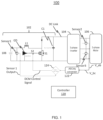
- a system 100 includes a boost converter 102, a 3-phase inverter 104, and a 3-phase motor or load 106.
- the boost converter 102 includes the power supply 108, the inductor L1, the diode D1, the gate drive GD, the switch S1, and the DC link capacitor C1.
- the power supply 108 is electrically coupled to the inductor L1 and increases the voltage of the inductor L1 when the switch S1 is closed.
- the gate driver GD is coupled to the control terminal of the switch S1 which is under the control of a control signal of a controller 120.
- the controller 120 may enter the boost mode of operation based on the power level of the power supply 108. For example, thresholds for various voltage levels and power levels can be used to determine when the system 100 should enter the boost mode or rectification mode of operation.
- the operation of the 3-phase inverter can be interrupted when the demand from the load 106 exceeds the capability of the power supply 108.
- the power supply 108 is a DC source such as a battery.
- the power supply 108 may be another type of DC source.
- the boost converter 102 can operate in a rectification mode to rectify the power from the power supply 108 to provide the required voltage for the load 106. In such a mode, the switch S2 is controlled open to prevent the boost operation of the boost converter 102.
- a first voltage sensor (“Sensor1”) is electrically coupled in parallel with the power supply 108 and detects the voltage that is output from the power supply 108.
- the "Sensor1 Output" from Sensor1 represents the voltage level of the power supply voltage level, is provided to the controller 120.
- a second voltage sensor (“Sensor2”) and a third voltage (“Sensor3) are electrically coupled in parallel to the AB phases and the BC phases that are output of the 3-phase inverter 104, respectively.
- Sensor2 and Sensor 3 provide the voltage levels V_AB and V_BC to the controller 120.
- the voltage levels V_AB and V_BC of the 3-phase inverter 104 are provided to an ABC/dq transformation module 122.
- the ABC/dq transformation module 122 can be incorporated in the controller 120.
- the DQ transform is used to simplify the analysis of 3-phase synchronous machines or to simplify calculations for the control of 3-phase inverters.
- the transformation transfers 3-phase stator and rotor quantities into a single rotating reference frame to eliminate the effect of time-varying inductances and transform the system into a linear time-invariant system.
- the transformation can be performed in the controller 120 and can be executed in either hardware, software, or any combination thereof.
- the controller 120 can compare the voltage levels at the 3-phase inverter output and the power supply 108.
- a comparator 124 receives the output from the ABC/dq transformation module 122 and compares the voltage level of the power supply 108 indicated by the Sensor1 Output.
- the comparator 124 can be performed in the controller 120.
- the comparator 124 can compare the absolute value of the voltage (Vdq) with a threshold voltage of the power supply 108. For example, the absolute value of the voltage
- the DCM control signal can be transmitted from the controller 120 to control the DCM switch S2.
- the DCM control signal can open and close the switch S2 to operate the boost converter 102 in a rectification mode (non-boosting mode) and a boost mode to increase the voltage to meet the demand of the load 106.
- the boost converter 102 can be operated in the rectification mode (non-boosting mode) when the DCM switch S2 is controlled to remain open, and the boost converter 102 can be operated in the boost mode when the DCM switch S2 is closed.
- the switch S1 can be switched according to the PWM signals provided from the controller 120 and is operable to increase or step-up the input voltage to a desired level when are operated in the boost mode.
- FIG. 2 illustrates a non-limiting example of the 3-phase inverter 104 shown in FIG. 1 .
- the 3-phase inverter 104 includes 3 pairs of transistors (T1, T4), (T2, T5), (T3, T6), where each pair of transistors are operated in a complementary fashion to generate a corresponding 3-phase output (A, B, C), respectively.
- the transistors T1-T6 may be implemented as metal-oxide semiconductor devices or other controllable devices such as bipolar junction transistors (BJT) devices, IGBT devices, or the like.
- BJT bipolar junction transistors
- Each of the control terminals of the transistors T1-T6 are electrically coupled to the controller 120.
- the arrangement of the 3-phase inverter can be operated using known techniques such as pulse-width modulation (PWM). It should be understood that other arrangement can be used to generate the 3-phase output.
- PWM pulse-width modulation
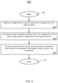
- FIG. 3 depicts a flowchart of a method 300 for controlling the boost converter 102 in accordance with one or more embodiments of the invention.
- the method 300 can be implemented in a system 100 such as that shown in FIG. 1 .
- the method 300 starts at block 302 and proceeds to block 304 which provides for receiving, at a controller, a voltage level of a power supply and a voltage level of a 3-phase inverter.
- the controller 120 can monitor and receive the output voltage levels corresponding to the DC battery source and the output of the 3-phase inverter. It can be appreciated the controller 120 can also receive other information from current sensors and/or voltage sensors arranged in the system 100.
- the controller 120 can determine the power from the voltage and current information obtained from the sensors coupled to the power supply, 3-phase inverter, load, etc.
- the boost operation of the boost converter 102 can be implemented based on exceeding a power threshold or a comparison between the output level and a percentage of the power supply.
- the voltage of the load or the motor approaches the rectified voltage of the boost converter 102 when operated in a rectification mode (non-boosting mode).
- the boost converter switches from the rectification mode to the boost mode, to supply the voltage that is demanded by the load.
- the stable operation of the boost converter 102 is enabled to avoid the DCM that is responsive to the detected conditions.
- Block 306 compares a power threshold to at least one of: the voltage level of the power supply and the voltage level of the 3-phase inverter.
- a threshold level that is 95% of power supply level can be used.
- the threshold can include a higher threshold such as 96%, 97%, etc. or a lower threshold such as 94%, 93%, etc. It should be understood the threshold is not intended to be limited by any of the examples described herein but can be any configurable to any value based upon the application.
- the 3-phase output of the 3-phase inverter is transformed to the dq-frame of reference. The transformation allows the controller 120 to compare the transformed 3-phase output to the DC voltage of the power supply 108. In one or more embodiments of the invention, the controller 120 can determine whether the output of the 3-phase inverter exceeds the threshold voltage of the power supply 108 or is below the threshold voltage.
- Block 308 controls an operation of the boost converter circuit to operate in a boost mode or a rectification mode based at least in part on the comparison.
- the controller when the voltage of the power supply or the voltage of the 3-phase inverter is greater than the power threshold, the controller is configured to operate the boost converter circuit in the boost mode.
- the controller 120 provides a control signal to the lo-side DCM switch to close the switch to enable the boost mode of the boost converter 102 to increase the voltage provided to the 3-phase inverter 104 and load 106.
- the boost converter 102 is prevented from entering DCM.
- the controller When the power of the power supply or the 3-phase inverter is less than the power threshold, the controller is configured to operate the boost converter circuit in the rectification mode. In the rectification mode, the controller holds the DCM switch open to prevent the PWM signals from entering the boost mode.
- the comparison further comprises comparing the voltage level of the power supply to at least one of: the voltage of the 3-phase inverter and a voltage level of a load.
- the controller 120 is configured to operate the boost converter in the boost mode.
- the controller is configured to operate the boost converter in the rectification mode.
- the method 300 ends at block 310. It should be understood that additional steps or a different sequence of steps can be included in various embodiments of the invention and is not intended to be limited by the steps shown in FIG. 3 .
- the technical effects and benefits include reducing losses from the battery-DC bus power electronics interface.
- the stability of the eTRU inverter is improved at low loads and the overall efficiency is improved by operating the boost converter in the rectification mode and the boost mode.
- the technical effects and benefits include being operable with variable-speed operation.
Abstract
Description
- The present invention relates to converters, and more specifically, to a system and a method for boost converter state control.
- Converters can be used to condition the power for various applications that may have different power requirements from the source. Therefore, there may be a need to increase the voltage supplied from a source using a boost converter or decrease the voltage using a buck converter. In addition, various types of converters can be used to modify direct current (DC) to alternating current (AC) and vice-versa, which depends on the various applications using the power. Electric transport refrigeration units often rely on converters to drive the load such as the compressors that are used to cool the cargo. There may be a need to provide a converter that efficiently interfaces with the compressor.
- According to a first aspect of the present invention, there is provided a system for controlling a boost converter circuit. The system includes a power supply operable to supply power to a load; a boost converter circuit coupled to the power supply, wherein the boost converter circuit is operable to provide power to the load; a 3-phase inverter coupled to the boost converter, wherein the 3-phase-inverter is operable to provide a 3-phase output; and a controller coupled to the boost converter and the 3-phase inverter. The controller is configured to receive a voltage level of a power supply and a voltage level of a 3-phase inverter; compare a power threshold to at least one of: the voltage level of the power supply and the voltage level of the 3-phase inverter; and control an operation of the boost converter circuit to operate in a boost mode or a rectification mode based at least in part on the comparison.
- The controller may be configured to operate the boost converter circuit in the boost mode when the voltage level of the power supply or the voltage level of the 3-phase inverter is greater than the power threshold.
- The controller may be configured to operate the boost converter circuit in the rectification mode when the voltage level of the power supply or the voltage level of the 3-phase inverter is less than the power threshold.
- The controller may be configured to compare the voltage level of the power supply to the voltage of the 3-phase inverter or a voltage level of the load.
- The controller may be configured to operate the boost converter circuit in the boost mode when the voltage level of the power supply is less than the voltage level of the 3-phase inverter or the voltage level of the load.
- The controller may be configured to operate the boost converter circuit in the rectification mode when the voltage level of the power supply is greater than the voltage level of the 3-phase inverter or the voltage level of the load.
- The system may include a transformation module that is configured to transform an output of the 3-phase inverter to a synchronous frame voltage level.
- The system may include a transformation module that performs an ABC-to-dq conversion.
- The system may include a direct current (DC) power supply.
- According to a second aspect of the present invention, there is provided a method for controlling a boost converter circuit. The method includes receiving, at a controller, a voltage level of a power supply and a voltage level of a 3-phase inverter; comparing a power threshold to at least one of: the voltage level of the power supply and the voltage level of the 3-phase inverter; and controlling an operation of the boost converter circuit to operate in a boost mode or a rectification mode based at least in part on the comparison.
- The method may include operating the boost converter circuit in the boost mode when the voltage level of the power supply or the voltage level of the 3-phase inverter is greater than the power threshold.
- The method may include operating the boost converter circuit in the rectification mode when power of the voltage level of the power supply or the voltage level of the 3-phase inverter is less than the power threshold.
- The method may include comparing the voltage level of the power supply to the voltage level of the 3-phase inverter or a voltage level of a load.
- The method may include operating the boost converter circuit in the boost mode when the voltage level of the power supply is less than at least one of: the voltage level of the 3-phase inverter and the voltage level of the load.
- The method may include operating the boost converter circuit in the rectification mode when the voltage level of the power supply is greater than at least one of: the voltage level of the 3-phase inverter and the voltage level of the load.
- The method may include transforming an output of the 3-phase inverter to a synchronous frame voltage level.
- The method may include a transformation that is an ABC-to-dq conversion.
- The power supply may be a direct current (DC) power supply.
- The foregoing features and elements may be combined in various combinations without exclusivity, unless expressly indicated otherwise. These features and elements as well as the operation thereof will become more apparent in light of the following description and the accompanying drawings. It should be understood, however, that the following description and drawings are intended to be illustrative and explanatory in nature and non-limiting.
- The following descriptions should not be considered limiting in any way. With reference to the accompanying drawings, like elements are numbered alike:
-
FIG. 1 illustrates an example system; -
FIG. 2 illustrates an example 3-phase inverter use in the system ofFIG. 1 ; and -
FIG. 3 illustrates a flowchart depicting an exemplary method for operating the boost converter to prevent the discontinuous mode (DCM). - Converters are often used to condition power for various loads. Due to the high-ripple currents of the electric transport refrigeration unit (eTRU), there is a high probability of the peak current being greater than the DC current of the boost converter. In this event, the boost converter will enter the discontinuous mode (DCM). In DCM, the inductor current of the
boost converter 102, such as that shown inFIG. 1 , can fall to zero which is very common in DC-to-DC converters and makes the DC voltage at the DC link capacitor uncontrollable. One or more embodiments of the techniques described herein prevents the converter from entering DCM by controlling the low-side insulated-gate bipolar transistor (IGBT) of the boost converter to operate the boost converter in the boost mode and further increases the efficiency by operating the converter in a rectification mode (non-boosting mode) during periods of low demand from the load. - In the event the motor, such as a compressor motor, presents a higher load to an inverter coupled to the boost converter, the boost converter will respond by enabling the boost mode operation of the circuit with a low-side IGBT and a high-side Schottky diode.
- In one or more embodiments of the invention, the switch is controlled based on a comparison of the abc-dq conversion. The comparison prevents the system from entering the DCM. The techniques described herein prevent the converter from entering DCM by the gate driver signals to the low-side IGBTs.
- In the embodiment shown in
FIG. 1 , asystem 100 includes aboost converter 102, a 3-phase inverter 104, and a 3-phase motor orload 106. In one or more embodiments of the invention, theboost converter 102 includes thepower supply 108, the inductor L1, the diode D1, the gate drive GD, the switch S1, and the DC link capacitor C1. Thepower supply 108 is electrically coupled to the inductor L1 and increases the voltage of the inductor L1 when the switch S1 is closed. The gate driver GD is coupled to the control terminal of the switch S1 which is under the control of a control signal of acontroller 120. - When the switch S1 is opened, the current from the inductor L1 is allowed to flow through the diode D1 and to the DC link and DC link capacitor C1. As the voltage is provided from the inductor L1, its magnetic field decreases and the inductor L1 will be periodically charged when the switch S1 is closed by the
controller 120. The normal operation of theboost converter 102 allows the inductor L1 to boost the voltage when the demand of theload 106 is increased. In one or more embodiments of the invention, thecontroller 120 may enter the boost mode of operation based on the power level of thepower supply 108. For example, thresholds for various voltage levels and power levels can be used to determine when thesystem 100 should enter the boost mode or rectification mode of operation. However, if there is not enough voltage provided from theboost converter 102, the operation of the 3-phase inverter can be interrupted when the demand from theload 106 exceeds the capability of thepower supply 108. In one or more embodiments, thepower supply 108 is a DC source such as a battery. Thepower supply 108 may be another type of DC source. When theload 106 requires a low power demand, theboost converter 102 can operate in a rectification mode to rectify the power from thepower supply 108 to provide the required voltage for theload 106. In such a mode, the switch S2 is controlled open to prevent the boost operation of theboost converter 102. - A first voltage sensor ("Sensor1") is electrically coupled in parallel with the
power supply 108 and detects the voltage that is output from thepower supply 108. The "Sensor1 Output" from Sensor1, represents the voltage level of the power supply voltage level, is provided to thecontroller 120. A second voltage sensor ("Sensor2") and a third voltage ("Sensor3) are electrically coupled in parallel to the AB phases and the BC phases that are output of the 3-phase inverter 104, respectively. Sensor2 andSensor 3 provide the voltage levels V_AB and V_BC to thecontroller 120. In one or more embodiments of the invention, the voltage levels V_AB and V_BC of the 3-phase inverter 104 are provided to an ABC/dq transformation module 122. In one or more embodiments of the invention, the ABC/dq transformation module 122 can be incorporated in thecontroller 120. As an example, the DQ transform is used to simplify the analysis of 3-phase synchronous machines or to simplify calculations for the control of 3-phase inverters. In the analysis of 3-phase synchronous machines, the transformation transfers 3-phase stator and rotor quantities into a single rotating reference frame to eliminate the effect of time-varying inductances and transform the system into a linear time-invariant system. It should be understood the transformation can be performed in thecontroller 120 and can be executed in either hardware, software, or any combination thereof. By transforming the 3-phase inverter output to the dq-frame, thecontroller 120 can compare the voltage levels at the 3-phase inverter output and thepower supply 108. - A
comparator 124 receives the output from the ABC/dq transformation module 122 and compares the voltage level of thepower supply 108 indicated by the Sensor1 Output. In one or more embodiments of the invention, thecomparator 124 can be performed in thecontroller 120. In some embodiments, thecomparator 124 can compare the absolute value of the voltage (Vdq) with a threshold voltage of thepower supply 108. For example, the absolute value of the voltage |Vdq| is compared to threshold voltage 95% of the power supply voltage (0.95 ∗ power supply voltage). In the event |Vdq| is equal to or exceeds 95%, the DCM switch S2 is closed to allow the inductor L1 to charge. The DCM control signal can be transmitted from thecontroller 120 to control the DCM switch S2. The DCM control signal can open and close the switch S2 to operate theboost converter 102 in a rectification mode (non-boosting mode) and a boost mode to increase the voltage to meet the demand of theload 106. In a non-limiting embodiment, theboost converter 102 can be operated in the rectification mode (non-boosting mode) when the DCM switch S2 is controlled to remain open, and theboost converter 102 can be operated in the boost mode when the DCM switch S2 is closed. During the boost mode the switch S1 can be switched according to the PWM signals provided from thecontroller 120 and is operable to increase or step-up the input voltage to a desired level when are operated in the boost mode. - One or more illustrative embodiments of the invention are described herein. Such embodiments are merely illustrative of the scope of this invention and are not intended to be limiting in any way. Accordingly, variations, modifications, and equivalents of embodiments disclosed herein are also within the scope of this invention.
-
FIG. 2 illustrates a non-limiting example of the 3-phase inverter 104 shown inFIG. 1 . The 3-phase inverter 104 includes 3 pairs of transistors (T1, T4), (T2, T5), (T3, T6), where each pair of transistors are operated in a complementary fashion to generate a corresponding 3-phase output (A, B, C), respectively. The transistors T1-T6 may be implemented as metal-oxide semiconductor devices or other controllable devices such as bipolar junction transistors (BJT) devices, IGBT devices, or the like. Each of the control terminals of the transistors T1-T6 are electrically coupled to thecontroller 120. The arrangement of the 3-phase inverter can be operated using known techniques such as pulse-width modulation (PWM). It should be understood that other arrangement can be used to generate the 3-phase output. -
FIG. 3 depicts a flowchart of amethod 300 for controlling theboost converter 102 in accordance with one or more embodiments of the invention. Themethod 300 can be implemented in asystem 100 such as that shown inFIG. 1 . Themethod 300 starts atblock 302 and proceeds to block 304 which provides for receiving, at a controller, a voltage level of a power supply and a voltage level of a 3-phase inverter. During the operation of theboost converter 102, thecontroller 120 can monitor and receive the output voltage levels corresponding to the DC battery source and the output of the 3-phase inverter. It can be appreciated thecontroller 120 can also receive other information from current sensors and/or voltage sensors arranged in thesystem 100. Additionally, thecontroller 120 can determine the power from the voltage and current information obtained from the sensors coupled to the power supply, 3-phase inverter, load, etc. In one or more embodiments of the invention, the boost operation of theboost converter 102 can be implemented based on exceeding a power threshold or a comparison between the output level and a percentage of the power supply. In such a scenario, the voltage of the load or the motor approaches the rectified voltage of theboost converter 102 when operated in a rectification mode (non-boosting mode). In a different scenario, when the load voltage at the output increases above a voltage threshold, the boost converter switches from the rectification mode to the boost mode, to supply the voltage that is demanded by the load. By implementing various thresholds to detect the voltage levels and power levels, the stable operation of theboost converter 102 is enabled to avoid the DCM that is responsive to the detected conditions. -
Block 306 compares a power threshold to at least one of: the voltage level of the power supply and the voltage level of the 3-phase inverter. In some embodiments, a threshold level that is 95% of power supply level can be used. The threshold can include a higher threshold such as 96%, 97%, etc. or a lower threshold such as 94%, 93%, etc. It should be understood the threshold is not intended to be limited by any of the examples described herein but can be any configurable to any value based upon the application. The 3-phase output of the 3-phase inverter is transformed to the dq-frame of reference. The transformation allows thecontroller 120 to compare the transformed 3-phase output to the DC voltage of thepower supply 108. In one or more embodiments of the invention, thecontroller 120 can determine whether the output of the 3-phase inverter exceeds the threshold voltage of thepower supply 108 or is below the threshold voltage. -
Block 308 controls an operation of the boost converter circuit to operate in a boost mode or a rectification mode based at least in part on the comparison. In one or more embodiments of the invention, when the voltage of the power supply or the voltage of the 3-phase inverter is greater than the power threshold, the controller is configured to operate the boost converter circuit in the boost mode. Thecontroller 120 provides a control signal to the lo-side DCM switch to close the switch to enable the boost mode of theboost converter 102 to increase the voltage provided to the 3-phase inverter 104 andload 106. By controlling the switch to operate in the boost mode upon the detection of the increased power demand, theboost converter 102 is prevented from entering DCM. When the power of the power supply or the 3-phase inverter is less than the power threshold, the controller is configured to operate the boost converter circuit in the rectification mode. In the rectification mode, the controller holds the DCM switch open to prevent the PWM signals from entering the boost mode. - In one or more embodiments of the invention, the comparison further comprises comparing the voltage level of the power supply to at least one of: the voltage of the 3-phase inverter and a voltage level of a load. When the voltage level of the power supply is less than at least one of: the voltage level of the 3-phase inverter and the voltage level of the load, the
controller 120 is configured to operate the boost converter in the boost mode. When the voltage level of the power supply is greater than at least one of: the voltage level of the 3-phase inverter and the voltage level of the load, the controller is configured to operate the boost converter in the rectification mode. - The
method 300 ends atblock 310. It should be understood that additional steps or a different sequence of steps can be included in various embodiments of the invention and is not intended to be limited by the steps shown inFIG. 3 . - The technical effects and benefits include reducing losses from the battery-DC bus power electronics interface. In addition, the stability of the eTRU inverter is improved at low loads and the overall efficiency is improved by operating the boost converter in the rectification mode and the boost mode. The technical effects and benefits include being operable with variable-speed operation.
- A detailed description of one or more embodiments of the disclosed apparatus and method are presented herein by way of exemplification and not limitation with reference to the Figures.
- The term "about" is intended to include the degree of error associated with measurement of the particular quantity based upon the equipment available at the time of filing the application.
- The terminology used herein is for the purpose of describing particular embodiments only and is not intended to be limiting of the present invention. As used herein, the singular forms "a", "an" and "the" are intended to include the plural forms as well, unless the context clearly indicates otherwise. It will be further understood that the terms "comprises" and/or "comprising," when used in this specification, specify the presence of stated features, integers, steps, operations, elements, and/or components, but do not preclude the presence or addition of one or more other features, integers, steps, operations, element components, and/or groups thereof.
- While the present invention has been described with reference to an exemplary embodiment or embodiments, it will be understood by those skilled in the art that various changes may be made and equivalents may be substituted for elements thereof without departing from the scope of the present invention. In addition, many modifications may be made to adapt a particular situation or material to the teachings of the present invention without departing from the scope thereof. Therefore, it is intended that the present invention not be limited to the particular embodiment disclosed as the best mode contemplated for carrying out this present invention, but that the present invention will include all embodiments falling within the scope of the claims.
Claims (15)
- A system (100) for controlling a boost converter circuit (102), the system comprising:a power supply (108) operable to supply power to a load (106);a boost converter circuit (102) coupled to the power supply (108), wherein the boost converter circuit (102) is operable to provide power to the load (106);a 3-phase inverter (104) coupled to the boost converter circuit (102), wherein the 3-phase-inverter is operable to provide a 3-phase output;a controller (120) coupled to the boost converter circuit (102) and the 3-phase inverter (104), wherein the controller is further configured to:receive a voltage level of a power supply (108) and a voltage level of a 3-phase inverter (104);compare a power threshold to at least one of: the voltage level of the power supply (108) and the voltage level of the 3-phase inverter (104); andcontrol an operation of the boost converter circuit (102) to operate in a boost mode or a rectification mode based at least in part on the comparison.
- The system of claim 1, wherein the controller (120) is further configured to operate the boost converter circuit (102) in the boost mode when the voltage level of the power supply (108) or the voltage level of the 3-phase inverter (104) is greater than the power threshold.
- The system of claim 1 or 2, wherein the controller (120) is further configured to operate the boost converter circuit (102) in the rectification mode when the voltage level of the power supply (108) or the voltage level of the 3-phase inverter (104) is less than the power threshold.
- The system of any preceding claim, wherein the controller (120) is further configured to compare the voltage level of the power supply (108) to the voltage of the 3-phase inverter (104) or a voltage level of the load (106).
- The system of claim 4, wherein the controller (120) is further configured to operate the boost converter circuit (102) in the boost mode when the voltage level of the power supply (108) is less than the voltage level of the 3-phase inverter (104) or the voltage level of the load (106).
- The system of claim 4 or 5, wherein the controller (120) is further configured to operate the boost converter circuit (120) in the rectification mode when the voltage level of the power supply (108) is greater than the voltage level of the 3-phase inverter (104) or the voltage level of the load (106).
- The system of any preceding claim, further comprising a transformation module (122) configured to transform an output of the 3-phase inverter (104) to a synchronous frame voltage level, optionally wherein the transformation module (122) performs an ABC-to-dq conversion.
- The system of any preceding claim, wherein the power supply (108) is a DC power supply.
- A method for controlling a boost converter circuit (102), the method comprising:receiving, at a controller (120), a voltage level of a power supply (108) and a voltage level of a 3-phase inverter (104);comparing a power threshold to at least one of: the voltage level of the power supply (108) and the voltage level of the 3-phase inverter (104); andcontrolling an operation of the boost converter circuit (102) to operate in a boost mode or a rectification mode based at least in part on the comparison.
- The method of claim 9, wherein when the voltage level of the power supply (108) or the voltage level of the 3-phase inverter (104) is greater than the power threshold, the boost converter circuit (102) is operated in the boost mode,
and/or
wherein when the voltage level of the power supply (108) or the voltage level of the 3-phase inverter (104) is less than the power threshold, the boost converter circuit (102) is operated in the rectification mode. - The method of claim 9 or 10, wherein the comparison further comprises comparing the voltage level of the power supply (108) to the voltage of the 3-phase inverter (104) or a voltage level of a load (106).
- The method of claim 11, wherein when the voltage level of the power supply (108) is less than at least one of: the voltage level of the 3-phase inverter (104) and the voltage level of the load (106), the boost converter circuit (102) is operated in the boost mode.
- The method of claim 11 or 12, wherein when the voltage level of the power supply (108) is greater than at least one of: the voltage level of the 3-phase inverter (104) and the voltage level of the load (106), the boost converter circuit (102) is operated in the rectification mode.
- The method of any of claims 9 to 13, further comprising transforming an output of the 3-phase inverter (104) to a synchronous frame voltage level, optionally wherein the transformation is an ABC-to-dq conversion.
- The method of any of claims 9 to 14, wherein the power supply (108) is a direct current (DC) power supply.
Applications Claiming Priority (1)
| Application Number | Priority Date | Filing Date | Title |
|---|---|---|---|
| US202163272746P | 2021-10-28 | 2021-10-28 |
Publications (1)
| Publication Number | Publication Date |
|---|---|
| EP4175164A1 true EP4175164A1 (en) | 2023-05-03 |
Family
ID=83690162
Family Applications (1)
| Application Number | Title | Priority Date | Filing Date |
|---|---|---|---|
| EP22200848.4A Pending EP4175164A1 (en) | 2021-10-28 | 2022-10-11 | Boost converter state control |
Country Status (3)
| Country | Link |
|---|---|
| US (1) | US20230134793A1 (en) |
| EP (1) | EP4175164A1 (en) |
| CN (1) | CN116054621A (en) |
Citations (2)
| Publication number | Priority date | Publication date | Assignee | Title |
|---|---|---|---|---|
| EP2922192A1 (en) * | 2014-03-18 | 2015-09-23 | Kabushiki Kaisha Yaskawa Denki | Power converter, power generating system, apparatus for controlling power converter, and method for controlling power converter |
| US9929636B2 (en) * | 2014-02-19 | 2018-03-27 | Mitsubishi Electric Corporation | DC power-supply device, motor drive device including the same, and refrigeration-cycle application device including the motor drive device |
-
2022
- 2022-10-07 US US17/962,004 patent/US20230134793A1/en active Pending
- 2022-10-11 EP EP22200848.4A patent/EP4175164A1/en active Pending
- 2022-10-27 CN CN202211325772.3A patent/CN116054621A/en active Pending
Patent Citations (2)
| Publication number | Priority date | Publication date | Assignee | Title |
|---|---|---|---|---|
| US9929636B2 (en) * | 2014-02-19 | 2018-03-27 | Mitsubishi Electric Corporation | DC power-supply device, motor drive device including the same, and refrigeration-cycle application device including the motor drive device |
| EP2922192A1 (en) * | 2014-03-18 | 2015-09-23 | Kabushiki Kaisha Yaskawa Denki | Power converter, power generating system, apparatus for controlling power converter, and method for controlling power converter |
Non-Patent Citations (1)
| Title |
|---|
| RAVI KIRAN S ET AL: "Voltage control of variable speed SEIG with Z-Source inverter", INDUSTRIAL ELECTRONICS AND APPLICATIONS (ICIEA), 2012 7TH IEEE CONFERENCE ON, IEEE, 18 July 2012 (2012-07-18), pages 844 - 849, XP032268507, ISBN: 978-1-4577-2118-2, DOI: 10.1109/ICIEA.2012.6360842 * |
Also Published As
| Publication number | Publication date |
|---|---|
| US20230134793A1 (en) | 2023-05-04 |
| CN116054621A (en) | 2023-05-02 |
Similar Documents
| Publication | Publication Date | Title |
|---|---|---|
| US7830036B2 (en) | Power electronic module pre-charge system and method | |
| EP2661802B1 (en) | Bidirectional buck-boost converter | |
| EP2144357A1 (en) | A switched dc-dc conversion system for isolating high frequency and a method thereof | |
| US9312692B2 (en) | System for charging an energy store, and method for operating the charging system | |
| US11683001B2 (en) | Motor driving apparatus | |
| US20130038140A1 (en) | Switching circuit | |
| US20120025609A1 (en) | Very high efficiency uninterruptible power supply | |
| US9397581B2 (en) | Power conversion apparatus that provides a release path for inductive energy accumulated in an inductive load | |
| EP3703247B1 (en) | Electric motor driving apparatus | |
| US11223237B2 (en) | High efficiency power converting apparatus and control method | |
| KR101911263B1 (en) | Power transforming apparatus and air conditioner including the same | |
| EP3051676A1 (en) | Switch device, power conversion device, motor drive device, fan, compressor, air conditioner, refrigerator, and freezer | |
| US10734900B2 (en) | Converter device, motor drive device, refrigerator, air conditioner, and heat-pump water heater | |
| EP2120320B1 (en) | Dc power supply device | |
| US10574168B2 (en) | Electrical motor device | |
| EP4175164A1 (en) | Boost converter state control | |
| CN111835215A (en) | Converter circuit, power conversion system, and motor drive device | |
| EP3471264B1 (en) | Power output device | |
| EP4190542A1 (en) | Power conversion device and metal processing device | |
| EP3100346B1 (en) | Unidirectional matrix converter with regeneration system | |
| CN107979297B (en) | AC/DC converter based on multiplexing inductance | |
| CN108736754B (en) | Power conversion device and air conditioner | |
| US20230308038A1 (en) | Electric motor system | |
| CN220775659U (en) | Device and variable frequency drive | |
| US20230261654A1 (en) | Drive device to drive semiconductor element, semiconductor device, and power conversion device |
Legal Events
| Date | Code | Title | Description |
|---|---|---|---|
| PUAI | Public reference made under article 153(3) epc to a published international application that has entered the european phase |
Free format text: ORIGINAL CODE: 0009012 |
|
| STAA | Information on the status of an ep patent application or granted ep patent |
Free format text: STATUS: THE APPLICATION HAS BEEN PUBLISHED |
|
| AK | Designated contracting states |
Kind code of ref document: A1 Designated state(s): AL AT BE BG CH CY CZ DE DK EE ES FI FR GB GR HR HU IE IS IT LI LT LU LV MC ME MK MT NL NO PL PT RO RS SE SI SK SM TR |
|
| STAA | Information on the status of an ep patent application or granted ep patent |
Free format text: STATUS: REQUEST FOR EXAMINATION WAS MADE |
|
| 17P | Request for examination filed |
Effective date: 20231103 |
|
| RBV | Designated contracting states (corrected) |
Designated state(s): AL AT BE BG CH CY CZ DE DK EE ES FI FR GB GR HR HU IE IS IT LI LT LU LV MC ME MK MT NL NO PL PT RO RS SE SI SK SM TR |