EP4175139A1 - Dispositif et procédé de fabrication d'une flexion d'un enroulement ondulé pour un enroulement de bobine d'une machine électrique - Google Patents
Dispositif et procédé de fabrication d'une flexion d'un enroulement ondulé pour un enroulement de bobine d'une machine électrique Download PDFInfo
- Publication number
- EP4175139A1 EP4175139A1 EP22203985.1A EP22203985A EP4175139A1 EP 4175139 A1 EP4175139 A1 EP 4175139A1 EP 22203985 A EP22203985 A EP 22203985A EP 4175139 A1 EP4175139 A1 EP 4175139A1
- Authority
- EP
- European Patent Office
- Prior art keywords
- bending
- wire material
- bending elements
- elements
- arrangement
- Prior art date
- Legal status (The legal status is an assumption and is not a legal conclusion. Google has not performed a legal analysis and makes no representation as to the accuracy of the status listed.)
- Granted
Links
- 238000004804 winding Methods 0.000 title claims abstract description 79
- 238000004519 manufacturing process Methods 0.000 title claims abstract description 16
- 238000005452 bending Methods 0.000 claims abstract description 327
- 239000000463 material Substances 0.000 claims abstract description 124
- 238000003780 insertion Methods 0.000 claims abstract description 8
- 230000037431 insertion Effects 0.000 claims abstract description 8
- 238000000034 method Methods 0.000 claims description 18
- 238000006073 displacement reaction Methods 0.000 description 7
- 230000015572 biosynthetic process Effects 0.000 description 2
- 238000003491 array Methods 0.000 description 1
- 230000000712 assembly Effects 0.000 description 1
- 238000000429 assembly Methods 0.000 description 1
- 239000004020 conductor Substances 0.000 description 1
- 230000008878 coupling Effects 0.000 description 1
- 238000010168 coupling process Methods 0.000 description 1
- 238000005859 coupling reaction Methods 0.000 description 1
- 230000001419 dependent effect Effects 0.000 description 1
- 230000007704 transition Effects 0.000 description 1
Images


Classifications
-
- H—ELECTRICITY
- H02—GENERATION; CONVERSION OR DISTRIBUTION OF ELECTRIC POWER
- H02K—DYNAMO-ELECTRIC MACHINES
- H02K15/00—Methods or apparatus specially adapted for manufacturing, assembling, maintaining or repairing of dynamo-electric machines
- H02K15/04—Methods or apparatus specially adapted for manufacturing, assembling, maintaining or repairing of dynamo-electric machines of windings, prior to mounting into machines
- H02K15/0435—Wound windings
- H02K15/0478—Wave windings, undulated windings
-
- B—PERFORMING OPERATIONS; TRANSPORTING
- B21—MECHANICAL METAL-WORKING WITHOUT ESSENTIALLY REMOVING MATERIAL; PUNCHING METAL
- B21F—WORKING OR PROCESSING OF METAL WIRE
- B21F1/00—Bending wire other than coiling; Straightening wire
- B21F1/004—Bending wire other than coiling; Straightening wire by means of press-type tooling
-
- B—PERFORMING OPERATIONS; TRANSPORTING
- B21—MECHANICAL METAL-WORKING WITHOUT ESSENTIALLY REMOVING MATERIAL; PUNCHING METAL
- B21F—WORKING OR PROCESSING OF METAL WIRE
- B21F1/00—Bending wire other than coiling; Straightening wire
- B21F1/04—Undulating
Definitions
- the invention relates to a device and a method for producing a bend in a wave winding for a coil winding of an electrical machine.
- a coil winding for a rotor or a stator of an electrical machine can be formed using a wave winding.
- a wire or wire material is bent by means of a bending device, so that the bent or formed wire material runs like a wave.
- the bending device has bending elements that are moved to create the bend so as to transform the original wire material into the wave winding
- WO 2019 / 101 272 A1 discloses a device and a method for bending a bend in a wave winding for a coil winding of an electrical machine, with a bending unit having a first holding element for holding a first segment of a wire to be bent, a second holding element for holding a second segment of the wire to be bent and at least has a bending die for bending a transition area of the wire between the first segment and the second segment.
- the first and the second holding element are engaged with one another via at least one mechanical control cam for controlling a relative pivoting and a relative displacement of the first and the second holding element.
- Several such bending units can be provided in a bending device.
- WO 2016 / 033 028 A1 discloses a device for bending a wire material, in which bending elements arranged on opposite sides are displaced to produce a wave winding by means of a linear movement transverse to the longitudinal direction of a wire to be bent and by means of another linear movement in the longitudinal direction of the wire to be bent.
- Another method for producing a wave winding by means of superimposed linear movements is in the document U.S. 7,624,768 B2 disclosed.
- document DE 10 2016 203 167 A1 relates to a device for producing a wavy Bent wire segment, in particular for use as a stator winding in an electrical machine, with a linear guide and with a plurality of forming tools which are mounted on the linear guide in a longitudinally displaceable and rotatable manner and which each have a receiving area for fixing the wire segment to be bent.
- the forming tools can be rotated in opposite directions and simultaneously moved together along the linear guide in order to be able to bend the wire segment fixed to it into a wave shape.
- the document JP 2009-213199 A discloses a method of manufacturing a wave-wound coil for stators.
- a portion constituting one end side is clamped with one end side clamp, and also a portion constituting the other end side is clamped with another end side clamp.
- Coil end conductors are formed from the end face forming sections by bringing the terminals relatively close to each other along a circular path while maintaining the parallel state between the terminals, thereby engaging them with each other and forming a slit part between the end face forming sections.
- the object of the invention is to specify a device and a method for producing a bend in a wave winding for a coil winding of an electrical machine, which makes it possible to efficiently bend a wire to be bent into a bend for a wave winding.
- a device for producing a bend in a wave winding for a coil winding of an electrical machine according to independent claim 1 is created as a solution. Furthermore, a method for producing a bend in a wave winding for a coil winding of an electrical machine according to independent claim 13 is created. Configurations are the subject of dependent subclaims.
- a device for producing a bend or geometric contour of a wave winding for a coil winding of an electrical machine which has a first arrangement of first bending elements and a second arrangement of second bending elements.
- the bending elements are each pivotably mounted about a first pivot axis, have a first bending head that is distal in relation to the first pivot axis and, after insertion and before bending of a wire material or wire in the longitudinal direction of the wire material, are on one side of the Arranged wire material in a respective first starting position.
- the second bending elements are each mounted pivotably about a second pivot axis and have a second bending head that is distal in relation to the second pivot axis and, after the insertion and before the bending of the wire material in the longitudinal direction of the wire material, are on an opposite side of the wire material in a respective second starting position arranged.
- the first bending elements can be pivoted from the first starting position from one side towards the inserted wire material into a first bending position and the second bending elements can be pivoted from the second starting position from the opposite side towards the inserted wire material into a second bending position .
- the first and second flexures upon pivoting respectively to the first and second bending positions, longitudinally form an array of adjacent pivoted flexures in which the wire material bent for wave winding passes around the first and second flexure heads and between adjacent flexures.
- the following is also provided: Pivoting the first bending elements from the first starting position from one side towards the inserted wire material into a first bending position and pivoting the second bending elements from the second starting position from the opposite side towards the inserted wire material into a second Bending position, wherein an arrangement of adjacent pivoted bending elements is formed with the first and the second bending elements after the respective pivoting into the first and the second bending position in the longitudinal direction, in which the wire material bent for wave winding around the first and the second bending heads and between adjacent bending elements runs.
- the apparatus and method enable the wire material to be bent efficiently to form the geometric contour or bend (bending contour) for the wave winding.
- the bending elements When the bending elements are pivoted into the bending position, they gradually come into contact with the wire material, particularly in the area of the respective bending head, which supports gentle processing of the wire material.
- first or second bending elements which can each be formed with a bending jaw, for example, in the respective arrangement can be selected depending on the application (number of shafts to be bent).
- At least one of the following configurations can be implemented: for the first bending elements of the first arrangement, a first axial spacing between first pivot axes of adjacent first bending elements remains the same when the first bending elements are moved from the first starting position into the first bending position; and for the second flexures of the second array, a second axial spacing between second pivot axes of adjacent second flexures is constant upon displacement of the second flexures from the second home position to the second flexure position. If the respective bending elements are moved from the starting position into the bending position by pivoting, the distance between the respective pivoting or rotating axes remains unchanged. In addition, it can be provided that the relative position for the pivot axes of the first and/or the second arrangement remains unchanged when pivoting between the starting position and the bending position.
- the first and the second bending elements can be arranged alternately.
- Such an arrangement can be formed by alternately displacing the first and the second bending elements from the opposite sides into the respective bending position.
- the arrangement of adjacent pivoted bending elements is then formed in such a way that in the longitudinal direction (of the unbent wire) a respective first bending element is followed by a respective second bending element.
- the first and second flexures may be arranged substantially transverse to the longitudinal direction.
- the first and the second bending elements can be arranged with their longitudinal direction transverse to the longitudinal direction of the wire material (before bending).
- the longitudinal direction extends, for example, along a connecting line between the bearing on the associated pivot axis or an area with this bearing and a central section of the bending head of the bending element.
- the first and the second bending elements can be displaceable for displacement from the respective bending position by means of a linear movement.
- the direction of movement of the linear movement can run, for example, transversely or at an angle to the longitudinal direction of the wire material before bending.
- the displacement by means of the linear movement makes it possible to move the first and the second arrangement with the respective bending elements away from the bent wire material (wave winding), so that the wave winding is released and can be removed from the bending device. Provision can be made for all first bending elements of the first arrangement and/or all second bending elements of the second arrangement to be displaceable together as a respective group of bending elements by means of the linear movement. Alternatively or additionally, it can be provided that the first and/or the second bending elements can be displaced individually or in subgroups by means of a linear movement, in particular away from the bent wire.
- first and second bending elements In the arrangement of the adjacent pivoted bending elements, mutually opposite surface sections of first and second bending elements, including a wire section of the wire material lying in between, can abut (on each other) at least in sections in a form-fitting manner.
- a form fit is formed at least in sections in the region of the opposing surface sections of the first and second bending elements, including a wire section of the wire material.
- the section of wire material rests both on the surface section of the first bending element and on a surface section of the opposite second bending element.
- the wire material bent for wave winding may be disposed in the array of adjacent pivoted flexures in a wire channel substantially continuously bounded by the first and second flexures along its entire channel length in the array of adjacent pivoted flexures.
- the bent wire material here runs along the wire channel, which extends (in the form of a wave) for example in the longitudinal direction of the wire material before bending. At least on two Opposite channel sides, the wire channel is delimited by the surface sections of the pivoted bending elements.
- At least the first bending heads of the first bending elements can be displaced towards the wire material by means of a linear movement in the longitudinal direction of the respective first bending element.
- post-bending can take place in such a way that the first and/or second bending heads are displaced by means of the linear movement in the longitudinal direction of the respective bending element (by means of an associated actuator) in order to bend the wire material into a desired final shape.
- the bending elements are mounted on the pivot axis with bearing play, which makes it possible to move the pivoted bending element in the linear direction with the aid of an associated actuator.
- a section of the bending element that is distal in relation to the pivot axis and on which the bending head is arranged can be extended or displaced relative to a proximal section of the bending element in order to carry out the linear movement for subsequent bending of the wire material.
- the distal and the proximal section of the bending element can be connected to one another, for example via a linear guide or linear coupling, which enables a relative displacement between the sections.
- the first and/or the second arrangement of bending elements can be set up to jointly carry out the linear movement for all associated bending elements.
- the bending elements of the arrangements are each set up to be moved linearly individually or in selected groups.
- a first bending element length of the first bending element and/or a second bending element length of the second bending element can be adjustable or changeable.
- the respective bending element can be designed with several element components (multi-part), which can be displaced relative to one another into different displacement positions, for example by means of a linear guide, and can be fixed relative to one another in the displacement positions in order to vary the bending element length.
- the bending element length is to be determined, for example, in the longitudinal direction of the bending element.
- the following can be provided in the device: along the first pivot axes, a plurality of first bending elements are arranged one above the other and pivotable about the assigned first pivot axis, and a plurality of second bending elements are arranged one above the other and pivotable about the assigned second pivot axis along the second pivot axes.
- This makes it possible to produce a plurality of layers, each of which is designed as a bend for a wave winding, in the same bending device, in particular simultaneously or sequentially in a uniform manufacturing process.
- the bending elements arranged one above the other can be pivotable together or individually (also in subgroups) between the starting position and the bending position.
- the bending elements arranged one above the other or next to one another along the pivot axis can be identical or different in terms of their external shape, for example with an identically or differently shaped bending head.
- the first arrangement of first bending elements and the second arrangement of second bending elements can be assigned at least on one side to a cover plate that is laterally adjacent to the first and the second arrangement and covers the surface of the latter.
- a respective such cover plate can be provided on the two opposite sides.
- the wire duct can be additionally delimited by means of one or both cover plates.
- the at least one cover plate can be used to provide a guide aid for the wire material, in particular in the case of edgewise wire, and/or the bending elements when pivoting between the initial position and the bending position.
- a starting wire contour generator can be arranged at the end, which is set up to form a starting wire contour on the end of the wire material and to hold the wire material after insertion.
- several starting wire contour sensors can be provided.
- a (respective) end section of the wire material or wire is shaped (bent) according to the start wire contour with the aid of the start wire contour generator(s). This can be the end section of the wire material, which is designed to run ahead in the direction of insertion when the wire material is inserted.
- the starting wire contour generator can have respective contour generator components on the two opposite sides of the (still unbent) wire material, which are shifted towards the wire material to form the starting wire contour in order to bend and then hold the end section.
- the wire material can be inserted by the wire material is drawn in from a supply of wire material, for example from a reel, using a gripping device.
- a gripping device When forming the starting wire contour, it can be provided that the wire material is released by the gripping device. If such a release has not yet taken place during the formation of the starting wire contour, this can be provided for afterwards.
- the manufacturing method can provide that when the first bending elements are pivoted into the first bending position and/or when the second bending elements are pivoted into the second bending position by means of the first and/or the second bending elements, further sections of the wire material are moved into an area between the first and the second bending elements are drawn in and bent. If the respective bending element comes into contact with the wire material when swiveling towards the bending position and this comes into contact with the bending element in the area of the bending head, the further swiveling of the bending element towards the bending position in this embodiment results in a further section of the wire material in inserted or retracted into the region between the first and second arrays of flexures.
- Such a tracking (additional drawing in) of the wire material supports a material-friendly bending of the wire material, which in this way is not stretched at all or is stretched to a lesser extent.
- the wire length required for the next bending section can be drawn into the bending device by the pivoting movement of the bending element. Because of this gradual retraction, the bending device can be designed to be very compact, even with small relative movements between the wire material and the bending elements. Pivoting the next bending element creates a bending contour, with a small relative movement between the wire material and bending element (for example bending jaw), which supports low wire stress in the device during bending and a minimal overall length for the device. A large part of the wire length that is required to generate the contour can be pulled through the device in the straight form of the wire material in the wire running direction.
- the manufacturing method can also provide that when the first and second bending elements are pivoted, the wire material is processed or bent essentially free of any relative movement between sections of a bending head surface and the wire material, at least in the region of the respective first and second bending head, after the wire material is in a respective section of the bending head surface comes into contact.
- the avoidance of a relative movement between the bending head and the wire material further supports a material-friendly bending process.
- One or more actuators can be assigned to the first and the second arrangement of bending elements, which are set up to displace the respective bending elements between the initial position and the bending position.
- a first actuator assigned to the first arrangement of first bending elements is provided, which is set up to successively shift the first bending elements from the starting position to the bending position by means of a linear movement along the first arrangement.
- the second arrangement of two bending elements can be assigned a second actuator, which by means of a linear movement along the second arrangement shifts the second bending elements one after the other from the starting position into the bending position.
- a control device that is coupled to the first and second actuators can be set up to control the movement of the first and second actuators relative to one another in such a way that a first and a second bending element are shifted alternately from the initial position to the bending position.
- Such a control of the pivoting processes for the bending elements is also possible with the help of alternative actuators, which, for example, are individually assigned to the bending elements and actuate them, either by means of a linear and/or pivoting movement of the actuator or actuators, in order to use the actuator movement to pivot the to cause bending elements.
- the first and second bending elements can be formed with guide depressions in the side area and in the area of the respective bending head, for example grooves, which are used to guide the wire material when the bend is produced.
- a wave winding for a coil winding of an electrical machine can be bent several times at the same time, with several wires or wire materials having different geometric bending contours being bent at the same time.
- the wires or wire materials may be placed between the first and second bending elements prior to bending to then be bent.
- the first and second bending elements each have first and second bending contours, which are assigned to one another and interact during bending in order to produce, for example, a first and a second bend with different geometric contours.
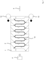
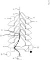
- Figures 1 to 8 show a schematic representation of an arrangement for a device for producing a bend or geometric contour of a wave winding for a coil winding of an electrical machine.
- a first arrangement 1 with first bending elements 2 is shown above a wire material or wire 3 which has been drawn in or inserted from a wire supply 5 with the aid of a gripping device 4 in such a way that the wire material 3 is in 1 extends in a longitudinal direction.
- a second arrangement 6 with second bending elements 7 is arranged below the wire material 3 .
- the first and the second bending elements 2, 7 are arranged in a respective first and second starting position in which the first and the second bending elements 2, 7 are not in contact with the wire material 3, which is, for example, a flat wire .
- the first and the second bending elements 2, 7 are pivoted about a respective pivot or rotation axis 2a, 7a.
- a bending head 2c, 7c is formed in a partial section 2b, 7b that is distal in relation to the respective pivot axis 2a, 7a.
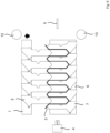
- the first arrangement 1 with the first bending elements 2 is shown in FIG 2 delivered to the second arrangement 6 with the second bending elements 7 .
- the first and the second bending elements 2, 7 are displaced from their respective initial position into a respective bending position towards the wire material 3, the wire material being bent in accordance with a wave shape.
- a first of the second bending elements 7 is fully shifted into its bending position and is then, in this example, transverse to the longitudinal direction of the wire material 3 before bending the 1 and 2 .
- the first and the second bending elements 2, 7 are alternately pivoted into the assigned bending position one after the other.
- further sections of the wire material 3 are drawn in from the wire supply 5 .
- the wire material 3 regularly comes into contact with the associated bending head 2c, 7c, then wraps itself around it and is drawn in further as the bending element continues to be pivoted.
- the first and the second actuator 12, 13 are generally set up to displace the first and the second bending elements 2, 7 from the starting position into the bending position.
- the first and second actuators 12, 13 are formed, for example, with a respective roller which is moved along the first and second assemblies 1, 2 in a staggered manner relative to one another in order to permit the pivoting of the first and second bending elements 2, 7 cause.
- the wire material 3 runs in a wire channel 14, which is delimited on opposite sides of the wire channel 14 by the first and the second bending elements 2, 7.
- the bending elements 2, 7 can be actuated by means of one or more associated actuators (not shown).
- a starting wire contour generator 20 is provided at the end of the first and second arrangement 1, 2, which has a first and second contour generator element 21, 22 on opposite sides of the wire material 3, which are moved towards one another at the beginning of the bending process in order to form a starting wire contour 23 at the end.
- one end 24 of the wire material 3 is released from the gripping device 4 .
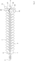
- the 11 and 12 show another arrangement for a device for producing a bend in a wave winding for a coil winding, in which the first and the second arrangement 1, 2 are formed with a plurality of first and second bending elements 30, 31 stacked on top of one another, which enable a plurality of layers 32 to be used as produce each bend of a wave winding.
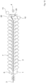
- FIG. 13 shows a schematic representation of an additional arrangement for a device for producing a bend in a wave winding for a coil winding, in which the first and the second arrangement 1, 2 have length-adjustable first and second bending elements 40, 41, in which a length adjustment in the longitudinal direction of the bending elements is possible in that a relative position between a component section 42 that is proximal in relation to the respective pivot axis and a distal component section 43 can be adjusted, for example using an associated linear guide on the bending element.
- the arrangement can be set up for producing bends for a wave winding with different strand lengths.
- FIG. 14 shows a schematic representation of a first and a second bending element 2, 7, in which guide depressions 50, 51 are formed in the side area 11 and in the area of the respective bending head 2c, 7c, which are used to guide the wire material 3 during the production of the bend.
- the Figures 15 to 18 show a schematic representation of an arrangement for a device for producing a plurality of bends in a wave winding for a coil winding of an electrical machine, with a plurality of wires 60, 61 being bent at the same time, but with different geometric bending contours.
- a device for producing a plurality of bends in a wave winding for a coil winding of an electrical machine with a plurality of wires 60, 61 being bent at the same time, but with different geometric bending contours.
- For the same characteristics are in the Figures 15 to 18 same characteristics as in the previous ones Figures 1 to 14 used.
- the wires or wire materials 60, 61 are placed between the first and second bending members 2, 7 similarly to the wire material 3 before bending. After Successive delivery of the first and the second bending elements 2, 7, these are then pivoted one after the other in order to produce a first bend 62 and a second bend 63, which are formed with different geometric contours and with a view to the plane of the drawing 17 and 18 are arranged one behind the other or one above the other. Finally, the first bending elements 2 are retracted in order to then be able to remove the first and second bends 62, 63.
- first and second bending elements 2, 7 each have first and second bending contours 64, 65 which are associated with one another and cooperate during bending to produce the first and second bends 62, 63 with different geometric contours.
Landscapes
- Engineering & Computer Science (AREA)
- Mechanical Engineering (AREA)
- Manufacturing & Machinery (AREA)
- Power Engineering (AREA)
- Manufacture Of Motors, Generators (AREA)
Applications Claiming Priority (1)
| Application Number | Priority Date | Filing Date | Title |
|---|---|---|---|
| DE102021128410.4A DE102021128410A1 (de) | 2021-11-01 | 2021-11-01 | Vorrichtung und Verfahren zum Herstellen einer Biegung einer Wellenwicklung für eine Spulenwicklung einer elektrischen Maschine |
Publications (3)
| Publication Number | Publication Date |
|---|---|
| EP4175139A1 true EP4175139A1 (fr) | 2023-05-03 |
| EP4175139B1 EP4175139B1 (fr) | 2024-07-31 |
| EP4175139C0 EP4175139C0 (fr) | 2024-07-31 |
Family
ID=84044092
Family Applications (1)
| Application Number | Title | Priority Date | Filing Date |
|---|---|---|---|
| EP22203985.1A Active EP4175139B1 (fr) | 2021-11-01 | 2022-10-27 | Dispositif et procédé de fabrication d'une flexion d'un enroulement ondulé pour un enroulement de bobine d'une machine électrique |
Country Status (2)
| Country | Link |
|---|---|
| EP (1) | EP4175139B1 (fr) |
| DE (1) | DE102021128410A1 (fr) |
Citations (8)
| Publication number | Priority date | Publication date | Assignee | Title |
|---|---|---|---|---|
| US2963048A (en) * | 1954-05-24 | 1960-12-06 | W F And John Barnes Company | Apparatus for bending wire articles |
| JP2009213199A (ja) | 2008-02-29 | 2009-09-17 | Aisin Aw Co Ltd | ステータ用波巻コイルの製造方法 |
| US7624768B2 (en) | 2006-05-30 | 2009-12-01 | Remy International, Inc. | Method and apparatus for forming a wire to include coil segments |
| WO2010079548A1 (fr) | 2009-01-08 | 2010-07-15 | アイシン・エィ・ダブリュ株式会社 | Appareil de cintrage et machine de cintrage |
| KR20150093992A (ko) * | 2014-02-10 | 2015-08-19 | 주식회사 액트파트너 | 래티스근 자동 연속 성형장치 및 이에 의해 제작된 래티스 연속 성형체 |
| WO2016033028A1 (fr) | 2014-08-25 | 2016-03-03 | Remy Technologies, Llc | Appareil de formage de fil destiné à un enroulement de machine électrique |
| DE102016203167A1 (de) | 2016-02-29 | 2017-08-31 | Zf Friedrichshafen Ag | Vorrichtung und Verfahren zum Herstellen eines wellenförmig gebogenen Drahtsegments |
| DE102017127634A1 (de) * | 2017-11-22 | 2019-05-23 | Grob-Werke Gmbh & Co. Kg | Einheit, Einrichtung, Vorrichtung und Verfahren zum Biegen und Herstellen von Wellenwicklungen für Spulenwicklungen elektrischer Maschinen |
Family Cites Families (4)
| Publication number | Priority date | Publication date | Assignee | Title |
|---|---|---|---|---|
| EP1270104B1 (fr) | 2000-02-17 | 2009-11-04 | Sanoh Kogyo Kabushiki Kaisha | Machine a plier |
| JP4506895B2 (ja) | 2008-04-07 | 2010-07-21 | 株式会社デンソー | 波巻きステータコイルの製造方法 |
| DE102019220415A1 (de) | 2019-12-20 | 2021-06-24 | Fraunhofer-Gesellschaft zur Förderung der angewandten Forschung eingetragener Verein | Vorrichtung und Verfahren zum Biegen von elektrisch leitenden Profilen für Elektromotoren (Hairpin) |
| EP3905493A1 (fr) | 2020-04-28 | 2021-11-03 | Grob-Werke GmbH & Co. KG | Dispositif de pliage et procédé de pliage destinés au pliage bidimensionnel d'un conducteur électrique |
-
2021
- 2021-11-01 DE DE102021128410.4A patent/DE102021128410A1/de active Pending
-
2022
- 2022-10-27 EP EP22203985.1A patent/EP4175139B1/fr active Active
Patent Citations (9)
| Publication number | Priority date | Publication date | Assignee | Title |
|---|---|---|---|---|
| US2963048A (en) * | 1954-05-24 | 1960-12-06 | W F And John Barnes Company | Apparatus for bending wire articles |
| US7624768B2 (en) | 2006-05-30 | 2009-12-01 | Remy International, Inc. | Method and apparatus for forming a wire to include coil segments |
| JP2009213199A (ja) | 2008-02-29 | 2009-09-17 | Aisin Aw Co Ltd | ステータ用波巻コイルの製造方法 |
| WO2010079548A1 (fr) | 2009-01-08 | 2010-07-15 | アイシン・エィ・ダブリュ株式会社 | Appareil de cintrage et machine de cintrage |
| KR20150093992A (ko) * | 2014-02-10 | 2015-08-19 | 주식회사 액트파트너 | 래티스근 자동 연속 성형장치 및 이에 의해 제작된 래티스 연속 성형체 |
| WO2016033028A1 (fr) | 2014-08-25 | 2016-03-03 | Remy Technologies, Llc | Appareil de formage de fil destiné à un enroulement de machine électrique |
| DE102016203167A1 (de) | 2016-02-29 | 2017-08-31 | Zf Friedrichshafen Ag | Vorrichtung und Verfahren zum Herstellen eines wellenförmig gebogenen Drahtsegments |
| DE102017127634A1 (de) * | 2017-11-22 | 2019-05-23 | Grob-Werke Gmbh & Co. Kg | Einheit, Einrichtung, Vorrichtung und Verfahren zum Biegen und Herstellen von Wellenwicklungen für Spulenwicklungen elektrischer Maschinen |
| WO2019101272A1 (fr) | 2017-11-22 | 2019-05-31 | Grob-Werke Gmbh & Co. Kg | Unité, moyen, dispositif et procédé de pliage et de production d'enroulements ondulés pour enroulements de bobine de machines électriques |
Also Published As
| Publication number | Publication date |
|---|---|
| DE102021128410A1 (de) | 2023-05-04 |
| EP4175139B1 (fr) | 2024-07-31 |
| EP4175139C0 (fr) | 2024-07-31 |
Similar Documents
| Publication | Publication Date | Title |
|---|---|---|
| EP3381108B1 (fr) | Procédé de fabrication d'un enroulement de bobine à déposer dans des gorges radialement ouvertes de stators et de rotors de machines électriques | |
| EP3659244B1 (fr) | Procédé et dispositif d'enroulement d'une natte d'enroulement ondulé ainsi que natte d'enroulement ondulé ainsi fabriquée | |
| EP3714534B1 (fr) | Unité, moyen, dispositif et procédé de pliage et de production d'enroulements ondulés pour enroulements de bobine de machines électriques | |
| EP3906607B1 (fr) | Procédé de cintrage, procédé de fabrication, dispositif de cintrage et dispositif de fabrication pour un tapis d'enroulement ondulé ainsi que tapis d'enroulement ondulé obtenu avec ce procédé | |
| DE102005032478A1 (de) | Verfahren zum Herstellen einer Wicklung einer elektrischen Maschine | |
| EP3616309B1 (fr) | Gabarit de bobinage, dispositif de bobinage et procédé de fonctionnement de ceux-ci pour réaliser des enroulements de bobine destinés à être insérés dans un stator | |
| DE102016203167A1 (de) | Vorrichtung und Verfahren zum Herstellen eines wellenförmig gebogenen Drahtsegments | |
| EP3534498A1 (fr) | Procédé et dispositif de fabrication d'un stator doté d'un enroulement à bobines à air réduites | |
| EP3840198A1 (fr) | Dispositif et procédé de flexion du fil pour un élément de machine d'une machine électrique | |
| DE102019117966A1 (de) | Verfahren zur Herstellung einer Spulenwicklung zum Einlegen in radial offene Nuten von Statoren oder Rotoren von Elektromaschinen | |
| EP3663015B1 (fr) | Machine de fabrication d'éléments de fil | |
| DE102018106980A1 (de) | Vorrichtung und Verfahren zum Biegen von Draht für die Herstellung von Maschinenelementen elektrischer Maschinen | |
| WO2019040961A1 (fr) | Procédé et dispositif de production automatisée d'un composant d'un stator ou d'un rotor d'un moteur électrique | |
| DE102019220415A1 (de) | Vorrichtung und Verfahren zum Biegen von elektrisch leitenden Profilen für Elektromotoren (Hairpin) | |
| EP3654502B1 (fr) | Procédé et dispositif de fabrication d'un agencement doté d'un support d'enroulement rainuré et un enroulement de bobine pour une machine électrique | |
| WO2017045873A1 (fr) | Installation et procédé pour produire une barre d'enroulement pour un enroulement de stator | |
| AT522828A1 (de) | Verfahren und Vorrichtung zum Bearbeiten eines Stator-Halbfabrikats | |
| WO2020187363A1 (fr) | Procédé et dispositif pour réaliser une insertion multicouche d'un mat de bobine dans un composant d'une machine électrique | |
| EP4175139B1 (fr) | Dispositif et procédé de fabrication d'une flexion d'un enroulement ondulé pour un enroulement de bobine d'une machine électrique | |
| EP3506469A1 (fr) | Bobineuse | |
| DE102021119592A1 (de) | Verfahren zur Herstellung einer optimierten Wickelkopfgeometrie und Spulenwicklung mit einer solchen Geometrie | |
| DE102019208227A1 (de) | Verfahren zur Herstellung einer Statorwicklung und Elektromaschine | |
| WO2019081516A1 (fr) | Procédé de fabrication d'une bobine électrique et dispositif d'enroulement | |
| EP3553927A1 (fr) | Dispositif d'enroulement ondulé et procédé d'enroulement ondulé | |
| EP3836370B1 (fr) | Dispositif de formation des têtes de conducteur d'épingle à cheveux |
Legal Events
| Date | Code | Title | Description |
|---|---|---|---|
| PUAI | Public reference made under article 153(3) epc to a published international application that has entered the european phase |
Free format text: ORIGINAL CODE: 0009012 |
|
| STAA | Information on the status of an ep patent application or granted ep patent |
Free format text: STATUS: THE APPLICATION HAS BEEN PUBLISHED |
|
| AK | Designated contracting states |
Kind code of ref document: A1 Designated state(s): AL AT BE BG CH CY CZ DE DK EE ES FI FR GB GR HR HU IE IS IT LI LT LU LV MC ME MK MT NL NO PL PT RO RS SE SI SK SM TR |
|
| STAA | Information on the status of an ep patent application or granted ep patent |
Free format text: STATUS: REQUEST FOR EXAMINATION WAS MADE |
|
| 17P | Request for examination filed |
Effective date: 20230613 |
|
| RBV | Designated contracting states (corrected) |
Designated state(s): AL AT BE BG CH CY CZ DE DK EE ES FI FR GB GR HR HU IE IS IT LI LT LU LV MC ME MK MT NL NO PL PT RO RS SE SI SK SM TR |
|
| GRAP | Despatch of communication of intention to grant a patent |
Free format text: ORIGINAL CODE: EPIDOSNIGR1 |
|
| STAA | Information on the status of an ep patent application or granted ep patent |
Free format text: STATUS: GRANT OF PATENT IS INTENDED |
|
| RIC1 | Information provided on ipc code assigned before grant |
Ipc: B21F 1/04 20060101ALN20240208BHEP Ipc: B21F 1/00 20060101ALN20240208BHEP Ipc: H02K 15/04 20060101AFI20240208BHEP |
|
| INTG | Intention to grant announced |
Effective date: 20240227 |
|
| P01 | Opt-out of the competence of the unified patent court (upc) registered |
Effective date: 20240415 |
|
| GRAS | Grant fee paid |
Free format text: ORIGINAL CODE: EPIDOSNIGR3 |
|
| GRAA | (expected) grant |
Free format text: ORIGINAL CODE: 0009210 |
|
| STAA | Information on the status of an ep patent application or granted ep patent |
Free format text: STATUS: THE PATENT HAS BEEN GRANTED |
|
| AK | Designated contracting states |
Kind code of ref document: B1 Designated state(s): AL AT BE BG CH CY CZ DE DK EE ES FI FR GB GR HR HU IE IS IT LI LT LU LV MC ME MK MT NL NO PL PT RO RS SE SI SK SM TR |
|
| REG | Reference to a national code |
Ref country code: CH Ref legal event code: EP Ref country code: GB Ref legal event code: FG4D Free format text: NOT ENGLISH |
|
| REG | Reference to a national code |
Ref country code: DE Ref legal event code: R096 Ref document number: 502022001354 Country of ref document: DE |
|
| REG | Reference to a national code |
Ref country code: IE Ref legal event code: FG4D Free format text: LANGUAGE OF EP DOCUMENT: GERMAN |
|
| U01 | Request for unitary effect filed |
Effective date: 20240822 |
|
| U07 | Unitary effect registered |
Designated state(s): AT BE BG DE DK EE FI FR IT LT LU LV MT NL PT RO SE SI Effective date: 20240903 |
|
| P04 | Withdrawal of opt-out of the competence of the unified patent court (upc) registered |
Free format text: CASE NUMBER: APP_49315/2024 Effective date: 20240830 |