EP4175120A1 - Control method, control device, and control program - Google Patents
Control method, control device, and control program Download PDFInfo
- Publication number
- EP4175120A1 EP4175120A1 EP21828010.5A EP21828010A EP4175120A1 EP 4175120 A1 EP4175120 A1 EP 4175120A1 EP 21828010 A EP21828010 A EP 21828010A EP 4175120 A1 EP4175120 A1 EP 4175120A1
- Authority
- EP
- European Patent Office
- Prior art keywords
- battery
- soc value
- vehicle
- discharge
- charge
- Prior art date
- Legal status (The legal status is an assumption and is not a legal conclusion. Google has not performed a legal analysis and makes no representation as to the accuracy of the status listed.)
- Pending
Links
Images




Classifications
-
- B—PERFORMING OPERATIONS; TRANSPORTING
- B60—VEHICLES IN GENERAL
- B60L—PROPULSION OF ELECTRICALLY-PROPELLED VEHICLES; SUPPLYING ELECTRIC POWER FOR AUXILIARY EQUIPMENT OF ELECTRICALLY-PROPELLED VEHICLES; ELECTRODYNAMIC BRAKE SYSTEMS FOR VEHICLES IN GENERAL; MAGNETIC SUSPENSION OR LEVITATION FOR VEHICLES; MONITORING OPERATING VARIABLES OF ELECTRICALLY-PROPELLED VEHICLES; ELECTRIC SAFETY DEVICES FOR ELECTRICALLY-PROPELLED VEHICLES
- B60L55/00—Arrangements for supplying energy stored within a vehicle to a power network, i.e. vehicle-to-grid [V2G] arrangements
-
- B—PERFORMING OPERATIONS; TRANSPORTING
- B60—VEHICLES IN GENERAL
- B60L—PROPULSION OF ELECTRICALLY-PROPELLED VEHICLES; SUPPLYING ELECTRIC POWER FOR AUXILIARY EQUIPMENT OF ELECTRICALLY-PROPELLED VEHICLES; ELECTRODYNAMIC BRAKE SYSTEMS FOR VEHICLES IN GENERAL; MAGNETIC SUSPENSION OR LEVITATION FOR VEHICLES; MONITORING OPERATING VARIABLES OF ELECTRICALLY-PROPELLED VEHICLES; ELECTRIC SAFETY DEVICES FOR ELECTRICALLY-PROPELLED VEHICLES
- B60L53/00—Methods of charging batteries, specially adapted for electric vehicles; Charging stations or on-board charging equipment therefor; Exchange of energy storage elements in electric vehicles
- B60L53/10—Methods of charging batteries, specially adapted for electric vehicles; Charging stations or on-board charging equipment therefor; Exchange of energy storage elements in electric vehicles characterised by the energy transfer between the charging station and the vehicle
- B60L53/14—Conductive energy transfer
-
- B—PERFORMING OPERATIONS; TRANSPORTING
- B60—VEHICLES IN GENERAL
- B60L—PROPULSION OF ELECTRICALLY-PROPELLED VEHICLES; SUPPLYING ELECTRIC POWER FOR AUXILIARY EQUIPMENT OF ELECTRICALLY-PROPELLED VEHICLES; ELECTRODYNAMIC BRAKE SYSTEMS FOR VEHICLES IN GENERAL; MAGNETIC SUSPENSION OR LEVITATION FOR VEHICLES; MONITORING OPERATING VARIABLES OF ELECTRICALLY-PROPELLED VEHICLES; ELECTRIC SAFETY DEVICES FOR ELECTRICALLY-PROPELLED VEHICLES
- B60L58/00—Methods or circuit arrangements for monitoring or controlling batteries or fuel cells, specially adapted for electric vehicles
- B60L58/10—Methods or circuit arrangements for monitoring or controlling batteries or fuel cells, specially adapted for electric vehicles for monitoring or controlling batteries
- B60L58/12—Methods or circuit arrangements for monitoring or controlling batteries or fuel cells, specially adapted for electric vehicles for monitoring or controlling batteries responding to state of charge [SoC]
- B60L58/14—Preventing excessive discharging
-
- B—PERFORMING OPERATIONS; TRANSPORTING
- B60—VEHICLES IN GENERAL
- B60L—PROPULSION OF ELECTRICALLY-PROPELLED VEHICLES; SUPPLYING ELECTRIC POWER FOR AUXILIARY EQUIPMENT OF ELECTRICALLY-PROPELLED VEHICLES; ELECTRODYNAMIC BRAKE SYSTEMS FOR VEHICLES IN GENERAL; MAGNETIC SUSPENSION OR LEVITATION FOR VEHICLES; MONITORING OPERATING VARIABLES OF ELECTRICALLY-PROPELLED VEHICLES; ELECTRIC SAFETY DEVICES FOR ELECTRICALLY-PROPELLED VEHICLES
- B60L58/00—Methods or circuit arrangements for monitoring or controlling batteries or fuel cells, specially adapted for electric vehicles
- B60L58/10—Methods or circuit arrangements for monitoring or controlling batteries or fuel cells, specially adapted for electric vehicles for monitoring or controlling batteries
- B60L58/16—Methods or circuit arrangements for monitoring or controlling batteries or fuel cells, specially adapted for electric vehicles for monitoring or controlling batteries responding to battery ageing, e.g. to the number of charging cycles or the state of health [SoH]
-
- G—PHYSICS
- G07—CHECKING-DEVICES
- G07C—TIME OR ATTENDANCE REGISTERS; REGISTERING OR INDICATING THE WORKING OF MACHINES; GENERATING RANDOM NUMBERS; VOTING OR LOTTERY APPARATUS; ARRANGEMENTS, SYSTEMS OR APPARATUS FOR CHECKING NOT PROVIDED FOR ELSEWHERE
- G07C5/00—Registering or indicating the working of vehicles
- G07C5/008—Registering or indicating the working of vehicles communicating information to a remotely located station
-
- G—PHYSICS
- G07—CHECKING-DEVICES
- G07C—TIME OR ATTENDANCE REGISTERS; REGISTERING OR INDICATING THE WORKING OF MACHINES; GENERATING RANDOM NUMBERS; VOTING OR LOTTERY APPARATUS; ARRANGEMENTS, SYSTEMS OR APPARATUS FOR CHECKING NOT PROVIDED FOR ELSEWHERE
- G07C5/00—Registering or indicating the working of vehicles
- G07C5/08—Registering or indicating performance data other than driving, working, idle, or waiting time, with or without registering driving, working, idle or waiting time
- G07C5/0808—Diagnosing performance data
-
- G—PHYSICS
- G07—CHECKING-DEVICES
- G07C—TIME OR ATTENDANCE REGISTERS; REGISTERING OR INDICATING THE WORKING OF MACHINES; GENERATING RANDOM NUMBERS; VOTING OR LOTTERY APPARATUS; ARRANGEMENTS, SYSTEMS OR APPARATUS FOR CHECKING NOT PROVIDED FOR ELSEWHERE
- G07C5/00—Registering or indicating the working of vehicles
- G07C5/08—Registering or indicating performance data other than driving, working, idle, or waiting time, with or without registering driving, working, idle or waiting time
- G07C5/0816—Indicating performance data, e.g. occurrence of a malfunction
- G07C5/0825—Indicating performance data, e.g. occurrence of a malfunction using optical means
-
- H—ELECTRICITY
- H02—GENERATION; CONVERSION OR DISTRIBUTION OF ELECTRIC POWER
- H02J—ELECTRIC POWER NETWORKS; CIRCUIT ARRANGEMENTS OR SYSTEMS FOR SUPPLYING OR DISTRIBUTING ELECTRIC POWER; SYSTEMS FOR STORING ELECTRIC ENERGY
- H02J13/00—Circuit arrangements for providing remote monitoring or remote control of equipment in a power distribution network
- H02J13/12—Monitoring network conditions, e.g. electrical magnitudes or operational status
-
- H—ELECTRICITY
- H02—GENERATION; CONVERSION OR DISTRIBUTION OF ELECTRIC POWER
- H02J—ELECTRIC POWER NETWORKS; CIRCUIT ARRANGEMENTS OR SYSTEMS FOR SUPPLYING OR DISTRIBUTING ELECTRIC POWER; SYSTEMS FOR STORING ELECTRIC ENERGY
- H02J3/00—Circuit arrangements for AC mains or AC distribution networks
- H02J3/28—Arrangements for balancing of the load in networks by storage of energy
- H02J3/32—Arrangements for balancing of the load in networks by storage of energy using batteries or super capacitors with converting means
- H02J3/322—Arrangements for balancing of the load in networks by storage of energy using batteries or super capacitors with converting means the battery being on-board an electric or hybrid vehicle, e.g. vehicle to grid arrangements [V2G], power aggregation, use of the battery for network load balancing, coordinated or cooperative battery charging
-
- H—ELECTRICITY
- H02—GENERATION; CONVERSION OR DISTRIBUTION OF ELECTRIC POWER
- H02J—ELECTRIC POWER NETWORKS; CIRCUIT ARRANGEMENTS OR SYSTEMS FOR SUPPLYING OR DISTRIBUTING ELECTRIC POWER; SYSTEMS FOR STORING ELECTRIC ENERGY
- H02J7/00—Circuit arrangements for charging or discharging batteries or for supplying loads from batteries
- H02J7/80—Circuit arrangements for charging or discharging batteries or for supplying loads from batteries including monitoring or indicating arrangements
- H02J7/82—Control of state of charge [SOC]
-
- B—PERFORMING OPERATIONS; TRANSPORTING
- B60—VEHICLES IN GENERAL
- B60L—PROPULSION OF ELECTRICALLY-PROPELLED VEHICLES; SUPPLYING ELECTRIC POWER FOR AUXILIARY EQUIPMENT OF ELECTRICALLY-PROPELLED VEHICLES; ELECTRODYNAMIC BRAKE SYSTEMS FOR VEHICLES IN GENERAL; MAGNETIC SUSPENSION OR LEVITATION FOR VEHICLES; MONITORING OPERATING VARIABLES OF ELECTRICALLY-PROPELLED VEHICLES; ELECTRIC SAFETY DEVICES FOR ELECTRICALLY-PROPELLED VEHICLES
- B60L2240/00—Control parameters of input or output; Target parameters
- B60L2240/40—Drive Train control parameters
- B60L2240/54—Drive Train control parameters related to batteries
- B60L2240/549—Current
-
- B—PERFORMING OPERATIONS; TRANSPORTING
- B60—VEHICLES IN GENERAL
- B60L—PROPULSION OF ELECTRICALLY-PROPELLED VEHICLES; SUPPLYING ELECTRIC POWER FOR AUXILIARY EQUIPMENT OF ELECTRICALLY-PROPELLED VEHICLES; ELECTRODYNAMIC BRAKE SYSTEMS FOR VEHICLES IN GENERAL; MAGNETIC SUSPENSION OR LEVITATION FOR VEHICLES; MONITORING OPERATING VARIABLES OF ELECTRICALLY-PROPELLED VEHICLES; ELECTRIC SAFETY DEVICES FOR ELECTRICALLY-PROPELLED VEHICLES
- B60L2250/00—Driver interactions
- B60L2250/16—Driver interactions by display
-
- B—PERFORMING OPERATIONS; TRANSPORTING
- B60—VEHICLES IN GENERAL
- B60L—PROPULSION OF ELECTRICALLY-PROPELLED VEHICLES; SUPPLYING ELECTRIC POWER FOR AUXILIARY EQUIPMENT OF ELECTRICALLY-PROPELLED VEHICLES; ELECTRODYNAMIC BRAKE SYSTEMS FOR VEHICLES IN GENERAL; MAGNETIC SUSPENSION OR LEVITATION FOR VEHICLES; MONITORING OPERATING VARIABLES OF ELECTRICALLY-PROPELLED VEHICLES; ELECTRIC SAFETY DEVICES FOR ELECTRICALLY-PROPELLED VEHICLES
- B60L2260/00—Operating Modes
- B60L2260/40—Control modes
- B60L2260/46—Control modes by self learning
-
- B—PERFORMING OPERATIONS; TRANSPORTING
- B60—VEHICLES IN GENERAL
- B60L—PROPULSION OF ELECTRICALLY-PROPELLED VEHICLES; SUPPLYING ELECTRIC POWER FOR AUXILIARY EQUIPMENT OF ELECTRICALLY-PROPELLED VEHICLES; ELECTRODYNAMIC BRAKE SYSTEMS FOR VEHICLES IN GENERAL; MAGNETIC SUSPENSION OR LEVITATION FOR VEHICLES; MONITORING OPERATING VARIABLES OF ELECTRICALLY-PROPELLED VEHICLES; ELECTRIC SAFETY DEVICES FOR ELECTRICALLY-PROPELLED VEHICLES
- B60L2260/00—Operating Modes
- B60L2260/40—Control modes
- B60L2260/50—Control modes by future state prediction
- B60L2260/54—Energy consumption estimation
-
- Y—GENERAL TAGGING OF NEW TECHNOLOGICAL DEVELOPMENTS; GENERAL TAGGING OF CROSS-SECTIONAL TECHNOLOGIES SPANNING OVER SEVERAL SECTIONS OF THE IPC; TECHNICAL SUBJECTS COVERED BY FORMER USPC CROSS-REFERENCE ART COLLECTIONS [XRACs] AND DIGESTS
- Y02—TECHNOLOGIES OR APPLICATIONS FOR MITIGATION OR ADAPTATION AGAINST CLIMATE CHANGE
- Y02B—CLIMATE CHANGE MITIGATION TECHNOLOGIES RELATED TO BUILDINGS, e.g. HOUSING, HOUSE APPLIANCES OR RELATED END-USER APPLICATIONS
- Y02B70/00—Technologies for an efficient end-user side electric power management and consumption
- Y02B70/30—Systems integrating technologies related to power network operation and communication or information technologies for improving the carbon footprint of the management of residential or tertiary loads, i.e. smart grids as climate change mitigation technology in the buildings sector, including also the last stages of power distribution and the control, monitoring or operating management systems at local level
-
- Y—GENERAL TAGGING OF NEW TECHNOLOGICAL DEVELOPMENTS; GENERAL TAGGING OF CROSS-SECTIONAL TECHNOLOGIES SPANNING OVER SEVERAL SECTIONS OF THE IPC; TECHNICAL SUBJECTS COVERED BY FORMER USPC CROSS-REFERENCE ART COLLECTIONS [XRACs] AND DIGESTS
- Y02—TECHNOLOGIES OR APPLICATIONS FOR MITIGATION OR ADAPTATION AGAINST CLIMATE CHANGE
- Y02T—CLIMATE CHANGE MITIGATION TECHNOLOGIES RELATED TO TRANSPORTATION
- Y02T10/00—Road transport of goods or passengers
- Y02T10/60—Other road transportation technologies with climate change mitigation effect
- Y02T10/70—Energy storage systems for electromobility, e.g. batteries
-
- Y—GENERAL TAGGING OF NEW TECHNOLOGICAL DEVELOPMENTS; GENERAL TAGGING OF CROSS-SECTIONAL TECHNOLOGIES SPANNING OVER SEVERAL SECTIONS OF THE IPC; TECHNICAL SUBJECTS COVERED BY FORMER USPC CROSS-REFERENCE ART COLLECTIONS [XRACs] AND DIGESTS
- Y02—TECHNOLOGIES OR APPLICATIONS FOR MITIGATION OR ADAPTATION AGAINST CLIMATE CHANGE
- Y02T—CLIMATE CHANGE MITIGATION TECHNOLOGIES RELATED TO TRANSPORTATION
- Y02T90/00—Enabling technologies or technologies with a potential or indirect contribution to GHG emissions mitigation
- Y02T90/10—Technologies relating to charging of electric vehicles
- Y02T90/16—Information or communication technologies improving the operation of electric vehicles
-
- Y—GENERAL TAGGING OF NEW TECHNOLOGICAL DEVELOPMENTS; GENERAL TAGGING OF CROSS-SECTIONAL TECHNOLOGIES SPANNING OVER SEVERAL SECTIONS OF THE IPC; TECHNICAL SUBJECTS COVERED BY FORMER USPC CROSS-REFERENCE ART COLLECTIONS [XRACs] AND DIGESTS
- Y04—INFORMATION OR COMMUNICATION TECHNOLOGIES HAVING AN IMPACT ON OTHER TECHNOLOGY AREAS
- Y04S—SYSTEMS INTEGRATING TECHNOLOGIES RELATED TO POWER NETWORK OPERATION, COMMUNICATION OR INFORMATION TECHNOLOGIES FOR IMPROVING THE ELECTRICAL POWER GENERATION, TRANSMISSION, DISTRIBUTION, MANAGEMENT OR USAGE, i.e. SMART GRIDS
- Y04S20/00—Management or operation of end-user stationary applications or the last stages of power distribution; Controlling, monitoring or operating thereof
- Y04S20/20—End-user application control systems
- Y04S20/242—Home appliances
Definitions
- the present disclosure relates to a technique for discharging power from a battery of a vehicle to an electrical device outside the vehicle.
- V2H vehicle to home
- V2B vehicle to building
- Patent Literature 1 discloses a technique for controlling charge and discharge of a battery of an electric vehicle by determining in advance different target values for charging and discharging of the battery for each predetermined time zone such as a midnight time zone and an activity time zone in consideration of reduction of an electricity rate and suppression of deterioration of the battery of the electric vehicle.
- Patent Literature 1 JP 2017-46421 A
- the present disclosure has been made in view of the above problems, and an object of the present disclosure is to suppress deterioration of a battery of a vehicle by giving due consideration to a past use history of the vehicle by an individual user.
- a control method is a control method of controlling a charge and discharge device that charges and discharges a battery of a vehicle, the method including, by a computer, acquiring a current SOC value of the battery, acquiring history information related to a past power consumption amount in the vehicle, inputting the history information having been acquired to a learned model that has learned a relationship between the past power consumption amount of the vehicle and a necessary power amount when the vehicle is used next, and acquiring prediction information related to the necessary power amount, determining whether the current SOC value is larger than an optimum SOC value determined in advance for suppressing deterioration of the battery, upon determination that the current SOC value is larger than the optimum SOC value, calculating a target value of an SOC value of the battery at a time of discharging the battery based on the current SOC value, the optimum SOC value, and the prediction information, and outputting, to the charge and discharge device, control information instructing to discharge power from the battery to an electrical device
- charge and discharge of the battery is controlled on a rule basis using a predetermined target value in consideration of suppressing deterioration of the battery. Therefore, deterioration of the battery of the vehicle may not be suppressed by giving due consideration to a past use history of the vehicle by an individual user.
- the battery is charged and discharged using a target value corresponding to the time zone. As a result, power necessary for using the vehicle for a long time cannot be obtained from the battery, and there may be a problem that the vehicle cannot be used as desired by the user.
- the present inventor has conceived the following aspects according to the present disclosure.
- a control method is a control method of controlling a charge and discharge device that charges and discharges a battery of a vehicle, the method including, by a computer, acquiring a current SOC value of the battery, acquiring history information related to a past power consumption amount in the vehicle, inputting the history information having been acquired to a learned model that has learned a relationship between the past power consumption amount of the vehicle and a necessary power amount when the vehicle is used next, and acquiring prediction information related to the necessary power amount, determining whether the current SOC value is larger than an optimum SOC value determined in advance for suppressing deterioration of the battery, upon determination that the current SOC value is larger than the optimum SOC value, calculating a target value of an SOC value of the battery at a time of discharging the battery based on the current SOC value, the optimum SOC value, and the prediction information, and outputting, to the charge and discharge device, control information instructing to discharge power from the battery to an electrical device outside the vehicle until the SOC value of
- the history information related to the past power consumption amount of the vehicle is input to the learned model that has learned the relationship between the past power consumption amount of the vehicle and the necessary power amount when the vehicle is used next, and thus the prediction information related to the necessary power amount when the vehicle is used next is acquired.
- the necessary power amount when the vehicle is used next can be known by giving due consideration to the past power consumption amount of the vehicle by an individual user.
- the control information instructing to discharge from the battery to the electrical device outside the vehicle is output to the charge and discharge device until the SOC value of the battery reaches the target value calculated on the basis of the current SOC value, the optimum SOC value, and the prediction information.
- the battery when the current SOC value is larger than the optimum SOC value and it is considered necessary to suppress the deterioration of the battery, the battery can be discharged from the battery to the electrical device outside the vehicle until the SOC value of the battery reaches the target value calculated by giving due consideration to the past power consumption amount of the vehicle by an individual user.
- the deterioration of the vehicle of the battery can be suppressed by giving due consideration to the past use history of the vehicle by an individual user.
- the history information input to the learned model may further include information indicating a past use date and time of the vehicle, and the prediction information may include prediction date and time information indicating a date and time when the vehicle is used next.
- the history information further including the information indicating the past use date and time of the vehicle is input to the learned model, and the prediction information acquired from the learned model includes the prediction date and time information indicating the date and time when the vehicle is used next.
- the determining may further include determining whether an unused time as a time from a current time to a date and time indicated by the prediction date and time information is longer than a predetermined time, and the calculating may include calculating the target value upon determination that the current SOC value is larger than the optimum SOC value and the unused time is longer than the predetermined time.
- this aspect when the current SOC value is larger than the optimum SOC value and the unused time is longer than the predetermined time, power is discharged from the battery to the electrical device outside the vehicle. Therefore, in this aspect, when the unused time is shorter than the predetermined time, and it is considered that deterioration of the battery due to non-use of the battery does not progress, discharge from the battery to the electrical device outside the vehicle can be avoided. As a result, in such a case, this aspect can avoid promoting deterioration of the battery by discharging from the battery to the electrical device outside the vehicle.
- the calculating may include calculating a necessary SOC value that covers the necessary power amount based on the prediction information, and calculating the optimum SOC value as the target value when the optimum SOC value is larger than the necessary SOC value.
- the battery when the optimum SOC value is larger than the necessary SOC value, power is discharged from the battery to the electrical device outside the vehicle until the SOC value of the battery reaches the optimum SOC value. Therefore, in this aspect, the battery can be discharged until the necessary power amount when the vehicle is used next can be covered and deterioration of the battery can be suppressed.
- the calculating may include calculating a necessary SOC value that covers the necessary power amount based on the prediction information, and when the optimum SOC value is smaller than or equal to the necessary SOC value, selecting a charge and discharge pattern having a minimum deterioration degree of the battery among a plurality of charge and discharge patterns determined in advance, based on the current SOC value, the optimum SOC value, and the necessary SOC value, and calculating the target value according to the charge and discharge pattern having been selected.
- the optimum SOC value when the optimum SOC value is smaller than or equal to the necessary SOC value, power is discharged from the battery to the electrical device outside the vehicle until the SOC value of the battery reaches the target value according to a charge and discharge pattern having the minimum deterioration degree of the battery. Therefore, in this aspect, when the battery is discharged to the optimum SOC value, the necessary power amount when the vehicle is used next cannot be covered, the battery is discharged to the target value according to the charge and discharge pattern having the minimum deterioration degree of the battery, and the deterioration of the battery can be suppressed as much as possible.
- the calculating may include, when the necessary SOC value is larger than the optimum SOC value and the current SOC value, selecting a charge and discharge pattern having a minimum deterioration degree of the battery, out of a first charge and discharge pattern of charging the battery to the necessary SOC value immediately before the vehicle is used next, and a second charge and discharge pattern of discharging the battery to the optimum SOC value immediately after a current point of time and charging the battery to the necessary SOC value immediately before the vehicle is used next, calculating the current SOC value as the target value when the first charge and discharge pattern is selected, and calculating the optimum SOC value as the target value when the second charge and discharge pattern is selected.
- the current SOC value is calculated as the target value when the charge and discharge pattern having the minimum deterioration degree of the battery is the first charge and discharge pattern
- the optimum SOC value is calculated as the target value when the charge and discharge pattern having the minimum deterioration degree of the battery is the second charge and discharge pattern.
- this aspect when the necessary SOC value is larger than the current SOC value, and the battery needs to be charged to cover the necessary power amount when the vehicle is used next, the battery is not charged or discharged, or the battery can be discharged to the optimum SOC value immediately after the current point of time in accordance with the charge and discharge pattern having the minimum deterioration degree of the battery.
- this aspect can suppress deterioration of the battery as much as possible until the vehicle is used next time.
- the calculating may include, when the necessary SOC value is larger than the optimum SOC value and smaller than the current SOC value, selecting a charge and discharge pattern having a minimum deterioration degree of the battery, among a second charge and discharge pattern of discharging the battery to the optimum SOC value immediately after a current point of time and charging the battery to the necessary SOC value immediately before the vehicle is used next, a third charge and discharge pattern of not charging or discharging the battery until the vehicle is used next, and a fourth charge and discharge pattern of discharging the battery to the necessary SOC value immediately after a current point of time and not charging or discharging the battery until the vehicle is used next, calculating the optimum SOC value as the target value when the second charge and discharge pattern is selected, calculating the current SOC value as the target value when the third charge and discharge pattern is selected, and calculating the necessary SOC value as the target value when the fourth charge and discharge pattern is selected.
- the optimum SOC value is calculated as the target value.
- the charge and discharge pattern having the minimum deterioration degree of the battery is the third charge and discharge pattern
- the current SOC value is calculated as the target value.
- the charge and discharge pattern having the minimum deterioration degree of the battery is the fourth charge and discharge pattern
- the necessary SOC value is calculated as the target value.
- this aspect when the necessary power amount can be covered without charging the battery but the battery needs to be charged to cover the necessary power amount if the battery is discharged to the optimum SOC value to suppress deterioration of the battery, the battery is not charged or discharged, or the battery can be discharged to the necessary SOC value or the optimum SOC value immediately after the current point of time in accordance with the charge and discharge pattern having the minimum deterioration degree of the battery.
- this aspect can suppress deterioration of the battery as much as possible until the vehicle is used next time.
- the charge and discharge pattern may include at least one of a first period in which the battery is not charged or discharged or a second period in which the battery is charged or discharged, a deterioration degree of the battery in the first period may be calculated by a product of the first period and a predetermined first deterioration coefficient associated with the current SOC value, and a deterioration degree of the battery in the second period may be calculated by a product of a charge or discharge amount of the battery in the second period and a predetermined second deterioration coefficient associated with a type of the battery.
- the deterioration degree of the battery in the first period included in the charge and discharge pattern and in which the battery is not charged or discharged is calculated by a product of the first period and a predetermined first deterioration coefficient associated with the current SOC value.
- the deterioration degree of the battery in the second period included in the charge and discharge pattern and in which the battery is charged or discharged is calculated by a product of a charge or discharge amount of the battery in the second period and a predetermined second deterioration coefficient associated with the type of the battery.
- the deterioration degree of the battery in each charge and discharge pattern including at least one of the first period or the second period can be appropriately calculated.
- the battery is not charged or discharged immediately after the current point of time in accordance with the charge and discharge pattern having the calculated minimum deterioration degree, and it is therefore possible to suppress deterioration of the battery as much as possible until the vehicle is used next.
- the outputting may include transmitting information inquiring whether to perform discharge indicated by the control information to a communication terminal owned by a user of the vehicle before outputting the control information, and outputting the control information when information indicating that the discharge indicated by the control information is to be performed is returned from the communication terminal.
- control information inquiring whether to perform discharge indicated by the control information is transmitted to a communication terminal owned by a user of the vehicle, and when information indicating that discharge indicated by the control information is to be performed is returned from the communication terminal, the control information is output. Therefore, in this aspect, when permission to perform the discharge indicated by the control information is obtained from the user, the discharge indicated by the control information can be performed. As a result, it is possible to prevent the battery from becoming an SOC value not intended by the user when the user uses the vehicle next.
- the outputting may include receiving an input of an SOC value that is larger than or equal to the target value and smaller than the current SOC value before outputting the control information, transmitting information inquiring whether to select a discharge mode of discharging the battery to the SOC value having been received to the communication terminal owned by the user of the vehicle, and outputting information instructing to discharge the battery in the discharge mode instead of the control information to the charge and discharge device when the information indicating that the discharge mode is to be selected is returned from the communication terminal.
- the battery when information indicating that the discharge mode is to be selected is returned from the communication terminal before the control information is output, the battery is discharged to the SOC value that is equal to or larger than the target value input in the communication terminal and smaller than the current SOC value.
- the battery can be discharged with a discharge amount desired by the user while deterioration of the battery is suppressed as much as possible.
- the present disclosure can also be implemented as a control program that causes a computer to execute each characteristic configuration included in the control method according to the above one aspect, or a control device that operates by the control program. It goes without saying that such a control program can be distributed via a computer-readable non-transitory recording medium such as a CD-ROM or a communication network such as the Internet.
- FIG. 1 is an overall configuration diagram of a vehicle discharge system 1.
- the vehicle discharge system 1 is a system that controls discharge from a battery 41 of a vehicle 4 to an electrical device 32 outside the vehicle 4.
- the vehicle discharge system 1 includes a building 3, a charge and discharge device 5, the vehicle 4, and a communication terminal 9 owned by a user who has made a contract for use of power supplied by a power system 8, and a server 2 (control device).
- the building 3 includes, for example, a residential home in which the user lives and a business premise and a factory owned by the user.
- the building 3 includes a distribution board 31 and the electrical device 32.
- the distribution board 31 distributes power supplied from the power system 8 to the electrical device 32 and the charge and discharge device 5.
- the electrical device 32 operates on the power distributed by the distribution board 31.
- the electrical device 32 includes an operation panel 321 including a touch panel and a display, a television, an air conditioner (not illustrated), and the like.
- the operation panel 321 displays information acquired from an external device and a predetermined operation screen on the display via a communication device 322 to be described later, and transmits information input to the operation screen by the user to the external device using the touch panel.
- the electrical device 32 includes the communication device 322 such as a router used when the operation panel 321 or the like performs communication via a network 7 such as a local area network (LAN), the Internet, a telephone network, or the like.
- a network 7 such as a local area network (LAN), the Internet, a telephone network, or the like.
- the charge and discharge device 5 is electrically connected to the distribution board 31.
- One end of a charging cable 51 is electrically connected to the charge and discharge device 5.
- the other end of the charging cable 51 is electrically connected to the vehicle 4 such as an electric vehicle including the battery 41 that is chargeable and dischargeable.
- the charge and discharge device 5 incorporates a communication circuit (not illustrated) for communicating with an external device via the network 7.
- the charge and discharge device 5 Upon receipt of control information indicating an instruction to charge a target charge amount of power from the server 2 to the battery 41 of the vehicle 4 using the built-in communication circuit, the charge and discharge device 5 charges the battery 41 in accordance with the control information. Specifically, the charge and discharge device 5 supplies the target charge amount of power distributed by the distribution board 31 to the battery 41 of the vehicle 4 via the charging cable 51, the target charge amount being indicated by the control information.
- the charge and discharge device 5 Upon receipt of control information indicating an instruction to discharge a target discharge amount of power from the server 2 from the battery 41 of the vehicle 4 to the electrical device 32 using the built-in communication circuit, the charge and discharge device 5 discharges power from the battery 41 to the electrical device 32 outside of the vehicle 4 in accordance with the control information. Specifically, the charge and discharge device 5 supplies the target discharge amount of power charged by the battery 41 to the electrical device 32 outside the vehicle 4 via the charging cable 51 and the distribution board 31, the target discharge amount being indicated by the control information.
- the vehicle 4 includes, for example, a vehicle provided with the battery 41 which is chargeable and dischargeable, such as an electric vehicle, a hybrid vehicle, and an electric bicycle.
- the vehicle 4 includes the battery 41, a storage 42, a communication unit 43, a sensor 44, a drive unit 45, and a controller 40.
- the battery 41 includes a chargeable secondary battery such as a lithium ion battery.
- the battery 41 is detachably connected to the charging cable 51 connected to the charge and discharge device 5.
- the battery 41 is charged by power supplied from the charge and discharge device 5 via the charging cable 51.
- the battery 41 supplies power charged by the battery 41 to the electrical device 32 outside the vehicle 4 via the charging cable 51 under control of the charge and discharge device 5.
- the storage 42 includes a non-volatile memory that stores a predetermined control program and a memory such as a RAM that temporarily stores information.
- the storage 42 stores various types of information related to control of charge and discharge of the battery 41.
- the storage 42 stores history information related to a past power consumption amount in the vehicle 4.
- the history information includes a use date and time of the vehicle 4 and information indicating a power consumption amount of the battery 41 at the use date and time.
- the information indicating the use date and time of the vehicle 4 includes information indicating the date and time when the vehicle 4 is started to be used.
- the information indicating the use date and time of the vehicle 4 may include the date and time when the use of the vehicle 4 is ended.
- the storage 42 also stores a current state of charge (SOC) value (hereinafter, current SOC value) of the battery 41.
- SOC state of charge
- the communication unit 43 includes a communication circuit for communicating with an external device such as the server 2 via the network 7.
- the communication unit 43 outputs information received from the external device to the controller 40, and transmits the information input from the controller 40 to the external device.
- the sensor 44 includes an SOC sensor, a timer, a power amount sensor, and the like, and detects the current SOC value of the battery 41, a current date and time, and a power consumption amount of the battery 41.
- the drive unit 45 includes a drive motor (not illustrated) or the like that controls a direction and rotation of wheels provided on a bottom surface of a body of the vehicle 4.
- the controller 40 includes a processor such as a central processing unit (CPU).
- the controller 40 controls each part of the vehicle 4 by executing the control program stored in the storage 42.
- the controller 40 stores information indicating the current date and time detected using the sensor 44 in the storage 42 as information indicating the use date and time of the vehicle 4 included in the history information.
- the controller 40 periodically detects the current SOC value of the battery 41 using the sensor 44 after the start of use of the vehicle 4 until the end of use of the vehicle 4.
- the controller 40 periodically updates the current SOC value stored in the storage 42 with the detected current SOC value.
- the controller 40 periodically detects the power consumption amount of the battery 41 using the sensor 44 after the start of use of the vehicle 4 until the end of use of the vehicle 4.
- the controller 40 periodically updates the information indicating the power consumption amount in the history information stored in the storage 42 and including the date and time when the use of the vehicle 4 is started as the information indicating the use date and time of the vehicle 4 with the information indicating a cumulative value of the power consumption amount detected from the date and time when the use of the vehicle 4 is started to a current time.
- the controller 40 Upon receipt of the control information indicating the instruction to transmit the current SOC value transmitted from the server 2 by the communication unit 43, the controller 40 causes the communication unit 43 to return the information indicating the current SOC value stored in the storage 42 to the server 2. Note that the present disclosure is not limited thereto, and the controller 40 may periodically transmit the information indicating the current SOC value to the server 2 by the communication unit 43.
- the controller 40 Upon receipt of the control information indicating the instruction to transmit the history information transmitted from the server 2 by the communication unit 43, the controller 40 causes the communication unit 43 to return the information indicating the history information stored in the storage 42 to the server 2.
- the communication terminal 9 is, for example, a smartphone, a tablet terminal, and/or a laptop computer owned by the user, and communicates various types of information with an external device via the network 7.
- the communication terminal 9 includes a display and a touch panel (not illustrated).
- the communication terminal 9 displays information received from the external device and a predetermined operation screen on the display, and transmits information input to the operation screen by the user to the external device using the touch panel.
- the server 2 communicates with the vehicle 4, the charge and discharge device 5, and the communication terminal 9 via the network 7, and controls discharge from the battery 41 of the vehicle 4 to the electrical device 32 outside the vehicle 4.
- the server 2 includes a storage 21, a communication unit 22, and a controller 20.
- the storage 21 includes a non-volatile memory that stores a predetermined control program and a memory such as a RAM that temporarily stores information.
- the storage 21 stores various types of information related to control to cause the charge and discharge device 5 to charge and discharge the battery 41 of the vehicle 4.
- the storage 21 stores a learned model 211 that has learned a relationship between the past power consumption amount of the vehicle 4 and a necessary power amount when the vehicle 4 is used next.
- the learned model 211 also learns the relationship between past use date and time of the vehicle 4 and date and time when the vehicle 4 is used next.
- the learned model 211 will be described later in detail.
- the storage 21 stores a predetermined optimum SOC value for suppressing deterioration of the battery 41.
- the optimum SOC value is determined to be an SOC value when deterioration of the battery 41 is most suppressed, for example, on the basis of an experimental value or the like. Note that the optimum SOC value is not limited to this value, and for example, a predetermined representative value within a range, such as at least a center value within a range of an SOC value capable of suppressing the deterioration of the battery 41, may be set as the optimum SOC value.
- the storage 21 stores information indicating a plurality of predetermined charge and discharge patterns in advance.
- the charge and discharge patterns define a procedure for charging and discharging the battery 41, and include at least one of a first period in which the battery 41 is not charged or discharged or a second period in which the battery 41 is charged or discharged. The charge and discharge patterns will be described later in detail.
- the storage 21 stores various coefficients used for calculating a deterioration degree of the battery 41.
- the coefficients include a first deterioration coefficient used for calculating a deterioration degree of the battery 41 in the first period in which the battery 41 is not charged or discharged, and a second deterioration coefficient used for calculating a deterioration degree of the battery 41 in the second period in which the battery 41 is charged or discharged.
- the first deterioration coefficient is a coefficient that varies depending on the current SOC value of the battery 41.
- the storage 21 stores a plurality of first deterioration coefficients in association with a plurality of current SOC values.
- the second deterioration coefficient that varies depending on a type of the battery 41 such as a lithium ion battery and a nickel hydrogen battery.
- the storage 21 stores a plurality of second deterioration coefficients in association with a plurality of types of battery 41.
- the communication unit 22 includes a communication circuit for communicating with an external device such as the vehicle 4.
- the communication unit 22 outputs information received from the external device to the controller 20, and transmits the information input from the controller 20 to the external device.
- the controller 20 includes a microcomputer (computer) provided with a CPU and the like.
- the controller 20 controls an operation of each part of the server 2 by executing the control program stored in the storage 21.
- the controller 20 functions particularly as a learning unit 200, a first acquisition unit 201, a second acquisition unit 202, a third acquisition unit 203, a determination unit 204, a calculator 205, and an output unit 206 by executing the control program stored in the storage 21.
- History information related to the past power consumption amount in the vehicle 4 is input to the learning unit 200.
- the history information includes the past use date and time of the vehicle 4 and information indicating a power consumption amount of the battery 41 at the use date and time.
- the learning unit 200 performs machine learning such as deep learning using a neural network by using the input history information, creates the learned model 211 that has learned a relationship between the past use date and time of the vehicle 4 and the power consumption amount at the use date and time, and the next use date and time of the vehicle 4 and a necessary power amount when the vehicle 4 is used at the date and time, and stores the learned model 211 in the storage 21.
- the learning unit 200 when history information including the use date and time of two consecutive uses of the vehicle 4 and the power consumption amount at the use date and time is input to the learning unit 200, the learning unit 200 performs machine learning with the history information of the first use as an explanatory variable and the history information of the second use as an objective variable. As a result, when the history information for one use is input, the learning unit 200 creates the learned model 211 that predicts the date and time when the vehicle 4 is used next and the necessary power amount when the vehicle 4 is used at the date and time. Note that the learned model 211 can also be created in units of days of the week instead of in units of date and time. In this case, the history information only needs to include a day of the week when the vehicle 4 is used and information indicating a power consumption amount of the battery 41 on the day.
- the first acquisition unit 201, the second acquisition unit 202, the third acquisition unit 203, the determination unit 204, the calculator 205, and the output unit 206 will be described later in detail.
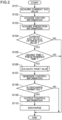
- FIG. 2 is a flowchart illustrating an example of the operation of the control for causing the charge and discharge device 5 to discharge the battery 41 of the vehicle 4.
- the first acquisition unit 201 acquires the current SOC value of the battery 41 (step S101). Specifically, in step S101, the first acquisition unit 201 controls the communication unit 22 to transmit the control information indicating the instruction to transmit the current SOC value to the vehicle 4. In response to this, as described above, when the information indicating the current SOC value is returned from the vehicle 4, the first acquisition unit 201 acquires the returned information indicating the current SOC value of the vehicle 4 via the communication unit 22.
- the second acquisition unit 202 acquires history information related to the past power consumption amount in the vehicle 4 (step S102). Specifically, in step S102, the second acquisition unit 202 controls the communication unit 22 to transmit the control information indicating the instruction to transmit the history information to the vehicle 4. In response to this, as described above, when the history information is returned from the vehicle 4, the second acquisition unit 202 acquires the returned history information via the communication unit 22. Note that the history information acquired in step S102 is input to the learning unit 200. When the history information is input, the learning unit 200 creates the learned model 211 using the input history information and stores the learned model 211 in the storage 21 as described above.
- the third acquisition unit 203 inputs history information corresponding to the latest use date and time acquired in step S102 to the learned model 211, and acquires prediction information related to the necessary power amount when the vehicle 4 is used next (step S103).
- the prediction information includes the information predicted by the learned model 211 and indicating the date and time when the vehicle 4 is used next and the necessary power amount when the vehicle 4 is used at the date and time.
- the determination unit 204 determines whether the current SOC value acquired in step S101 is larger than or equal to the optimum SOC value stored in the storage 21 (step S104).
- step S104 Upon determination in step S104 that the current SOC value is not larger than or equal to the optimum SOC value (NO in step S104), the controller 20 ends the operation of the discharge control. This avoids discharge of the battery 41 when the current SOC value is smaller than the optimum SOC value and the battery 41 may deteriorate even if the battery 41 is left unused. Consequently, the battery 41 is prevented from being deteriorated progressively due to discharge of the battery 41.
- step S104 determines whether unused time as time from the current time until the date and time when the vehicle 4 is used next is longer than a predetermined time (step S105).
- the determination unit 204 acquires information that is included in the prediction information acquired in step S103 and indicates the date and time when the vehicle 4 is used next (hereinafter, prediction date and time information).
- the determination unit 204 calculates time from the current time to the date and time indicated by the acquired prediction date and time information as the unused time, and determines whether the calculated unused time is longer than a predetermined time.
- the predetermined time is determined to be, for example, time from when the battery 41 whose SOC value is not the optimum SOC value is started to be left unused until deterioration occurs in the battery 41 (for example, 24 hours), on the basis of an experimental value or the like.
- step S105 Upon determination in step S105 that the unused time is not larger than the predetermined time (NO in step S105), the controller 20 ends the operation of the discharge control.
- This avoids discharge of the battery 41 when the vehicle 4 is predicted to be used within the predetermined time and the battery 41 may not be deteriorated even if the battery 41 is left unused. Consequently, the battery 41 is prevented from being deteriorated progressively due to discharge of the battery 41. It is also possible to avoid hindering the use of the vehicle 4 by the user due to discharge of the battery 41.
- step S105 upon determination in step S105 that the unused time is longer than the predetermined time (YES in step S105), the calculator 205 calculates a target value of the SOC value of the battery 41 at a time of discharging the battery 41 on the basis of the current SOC value acquired in step S101, the optimum SOC value stored in the storage 21, and the prediction information acquired in step S103 (step S106). Step S106 will be described later in detail.
- the output unit 206 generates control information instructing to discharge power from the battery 41 to the electrical device 32 outside the vehicle 4 until the SOC value of the battery 41 reaches the target value calculated in step S106 (step S107). Specifically, the output unit 206 calculates a result obtained by subtracting the current SOC value acquired in step S101 from the target value calculated in step S106 as a target discharge amount to be discharged from the battery 41 to the electrical device 32. Then, the output unit 206 generates, as control information, information indicating an instruction to discharge the target discharge amount of power from the battery 41 of the vehicle 4 to the electrical device 32.
- the output unit 206 inquires of the user of the vehicle 4 whether to permit the discharge indicated by the control information generated in step S107 to be performed (step S108).
- step S108 the output unit 206 controls the communication unit 22 to transmit information inquiring whether to perform the discharge indicated by the control information generated in step S107 (hereinafter, inquiry information) to the communication terminal 9 owned by the user of the vehicle 4.
- inquiry information information inquiring whether to perform the discharge indicated by the control information generated in step S107 (hereinafter, inquiry information) to the communication terminal 9 owned by the user of the vehicle 4.
- the output unit 206 acquires, via the communication unit 22, information returned from the communication terminal 9 and indicating that the discharge indicated by the control information is not to be performed until a predetermined time elapses after the transmission of the inquiry information. In this case, the output unit 206 determines that the user of the vehicle 4 has not permitted the discharge indicated by the control information to be performed (NO in step S108). When the communication unit 22 does not receive a reply from the communication terminal 9 at a point of time when the predetermined time has elapsed after the transmission of the inquiry information, the output unit 206 determines that the user of the vehicle 4 has not permitted the discharge indicated by the control information to be performed (NO in step S108). In these cases, the controller 20 terminates the operation of the discharge control.
- the output unit 206 determines that the user of the vehicle 4 has permitted the discharge indicated by the control information to be performed (YES in step S108).
- the output unit 206 transmits the control information generated in step S107 to the charge and discharge device 5 (step S109).
- the charge and discharge device 5 discharges power from the battery 41 to the electrical device 32 outside the vehicle 4 in accordance with the control information (step S110).
- the charge and discharge device 5 supplies the target discharge amount of power charged by the battery 41 to the electrical device 32 outside the vehicle 4 via the charging cable 51 and the distribution board 31, the target discharge amount being indicated by the control information.
- FIG. 3 is a flowchart illustrating an example of the processing of calculating the target value of the SOC value of the battery 41 at the time of discharging the battery 41.
- the calculator 205 calculates a necessary SOC value capable of covering the necessary power amount when the vehicle 4 is used next on the basis of the prediction information acquired in step S103 (step S201).
- the calculator 205 calculates, as the necessary SOC value, a sum of the SOC value of the battery 41 corresponding to the necessary power amount when the vehicle 4 is used next indicated by the prediction information and a predetermined margin SOC value.
- the predetermined margin SOC value is an SOC value set as a margin such that the battery 41 can cover the necessary power amount of power, that is, in order to reliably discharge the necessary power amount of power from the battery 41.
- the predetermined margin SOC value may be 0 or does not have to be set.
- the calculator 205 determines whether the optimum SOC value stored in step the storage 21 is larger than the necessary SOC value calculated in step S201 (step S202).
- step S202 Upon determination in step S202 that the optimum SOC value is larger than the necessary SOC value (YES in step S202), the calculator 205 calculates the optimum SOC value as the target value (step S203).
- step S107 a result obtained by subtracting the current SOC value acquired in step S101 from the optimum SOC value as the target value is calculated as the target discharge amount, and control information indicating an instruction to discharge the target discharge amount of power from the battery 41 of the vehicle 4 to the electrical device 32 is generated.
- step S110 the target discharge amount of power is discharged from the battery 41 of the vehicle 4 to the electrical device 32.
- the SOC value of the battery 41 becomes the optimum SOC value, and the deterioration of the battery 41 is suppressed.
- step S202 upon determination in step S202 that the optimum SOC value is smaller than or equal to the necessary SOC value (NO in step S202), the calculator 205 performs processing in and after step S210.
- the calculator 205 selects a charge and discharge pattern having a minimum deterioration degree of the battery 41 among the plurality of predetermined charge and discharge patterns on the basis of the current SOC value, the optimum SOC value, and the necessary SOC value, and calculates the target value according to the selected charge and discharge pattern.
- step S202 upon determination in step S202 that the optimum SOC value is smaller than or equal to the necessary SOC value (NO in step S202), the calculator 205 determines whether the necessary SOC value calculated in step S201 is larger than the current SOC value (step S210).
- the calculator 205 determines whether it is necessary to charge the battery 41 in order to cause the battery 41 to supply the necessary power amount when the vehicle 4 is used next indicated by the prediction information at the date and time when the vehicle 4 is used next indicated by the prediction date and time information included in the prediction information acquired in step S103 ( FIG. 2 ).
- step S210 upon determination in step S210 that the necessary SOC value is larger than the current SOC value (YES in step S210), the calculator 205 selects a first charge and discharge pattern and a second charge and discharge pattern for setting the SOC value of the battery 41 at the date and time when the vehicle 4 is used next as the necessary SOC value (step S211).
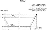
- FIG. 4 is a diagram illustrating an example of a first charge and discharge pattern G11 and a second charge and discharge pattern G12.
- a horizontal axis represents an elapsed time from a current point of time
- a vertical axis represents the SOC value of the battery 41.
- 0 indicates the current point of time
- T represents an elapsed time from the current point of time to the date and time when the vehicle 4 is used next, indicated by the prediction date and time information included in the prediction information acquired in step S103 ( FIG. 2 ).
- Qn represents the necessary SOC value
- Qc represents the current SOC value
- Qo represents the optimum SOC value.
- the first charge and discharge pattern G11 is a charge and discharge pattern in which the battery 41 is not charged or discharged until immediately before the next use of the vehicle 4, and the battery 41 is charged to the necessary SOC value Qn immediately before the next use of the vehicle 4.
- the second charge and discharge pattern G12 is a charge and discharge pattern in which the battery 41 is discharged to the optimum SOC value Qo immediately after the current point of time, thereafter, the battery 41 is not charged or discharged until immediately before the next use of the vehicle 4, and the battery 41 is charged to the necessary SOC value Qn immediately before the next use of the vehicle 4.
- the calculator 205 determines a charge and discharge pattern having a minimum deterioration degree of the battery 41 of the first charge and discharge pattern G11 or the second charge and discharge pattern G12 selected in step S211 (step S212).
- the calculator 205 calculates the deterioration degree of the battery 41 in the first period in which the battery 41 is not charged or discharged by a product of the first period and a predetermined first deterioration coefficient associated with the current SOC value Qc.
- the calculator 205 calculates the deterioration degree of the battery 41 in the second period in which the battery 41 is charged or discharged by a product of a charge and discharge amount of the battery 41 in the second period and a predetermined second deterioration coefficient associated with the type of the battery 41.
- the calculator 205 calculates a deterioration degree D1 of the battery 41 in the first charge and discharge pattern G11 using the following Equation (1).
- D 1 T 1 ⁇ K 1 Qc + Qn ⁇ Qc ⁇ K 2 Li
- T1 represents the first period during which the battery 41 is not charged or discharged.
- the first period T1 included in the first charge and discharge pattern G11 corresponds to a period from the current point of time to a time t3 as shown in FIG. 4 .
- the first period T1 may be approximated by a period (T - 0) from the current time to the next use of the vehicle 4.
- K1 [Qc] represents a first deterioration coefficient associated with the current SOC value Qc.
- Li indicates that the type of the battery 41 is a lithium ion battery
- K2 [Li] indicates a second deterioration coefficient associated with the lithium ion battery.
- the calculator 205 calculates a deterioration degree D2 of the battery 41 in the second charge and discharge pattern G12 using the following Equation (2).
- D 2 Qc ⁇ Qo ⁇ K 2 Li + Ti ⁇ K 1 Qc + Qn ⁇ Qo ⁇ K 2 Li
- T1 represents the first period during which the battery 41 is not charged or discharged.
- the first period T1 included in the second charge and discharge pattern G12 corresponds to a period (t2 - t1) shown in FIG. 4 from a point of time when a time t1 has elapsed from the current point of time to a point of time when a time t2 has elapsed from the current point of time.
- the first period T1 may be approximated by a period (T - 0) from the current time to the next use of the vehicle 4.
- K1 [Qc] and K2 [Li] represent, as in Equation (1), the first deterioration coefficient associated with the current SOC value Qc and the second deterioration coefficient associated with the lithium ion battery, respectively.
- a method of calculating the deterioration degree of the battery 41 in each charge and discharge pattern described above is merely an example, and the deterioration degree of the battery 41 in each charge and discharge pattern may be calculated by another calculation method.
- step S212 Upon determination in step S212 that the charge and discharge pattern having the minimum deterioration degree of the battery 41 is the first charge and discharge pattern G11 (first in step S212), the calculator 205 calculates the current SOC value Qc as the target value of the SOC value of the battery 41 at the time of discharging the battery 41 (step S213).
- step S107 which is a result obtained by subtracting the current SOC value Qc acquired in step S101 from the current SOC value Qc as the target value, is calculated as the target discharge amount.
- the output unit 206 since it is not necessary to discharge power from the battery 41 to the electrical device 32, the output unit 206 does not perform processing in and after step S108 ( FIG. 2 ), and the controller 20 ends the operation of the discharge control. In this case, power is not discharged from the battery 41 of the vehicle 4 to the electrical device 32, and as shown in the first charge and discharge pattern G11 ( FIG. 4 ), the battery 41 is left without being charged or discharged immediately after the current point of time.
- step S107 the output unit 206 may generate control information indicating an instruction to discharge power of a target discharge amount of 0 from the battery 41 of the vehicle 4 to the electrical device 32 and perform the processing in and after step S108.
- step S110 the target discharge amount of 0 is discharged from the battery 41 of the vehicle 4 to the electrical device 32. That is, power is not actually discharged from the battery 41 of the vehicle 4 to the electrical device 32, and as shown in the first charge and discharge pattern G11 ( FIG. 4 ), the battery 41 is left without being charged or discharged immediately after the current point of time.
- step S212 upon determination in step S212 that the charge and discharge pattern having the minimum deterioration degree of the battery 41 is the second charge and discharge pattern G12 (second in step S212), the calculator 205 calculates the optimum SOC value Qo as the target value of the SOC value of the battery 41 at the time of discharging the battery 41 (step S214).
- step S107 a result obtained by subtracting the current SOC value Qc acquired in step S101 from the optimum SOC value Qo as the target value is calculated as the target discharge amount, and the control information indicating an instruction to discharge the target discharge amount of power from the battery 41 of the vehicle 4 to the electrical device 32 is generated.
- step S110 FIG. 2
- step S110 immediately after the current point of time, power is discharged from the battery 41 to the electrical device 32 until the SOC value of the battery 41 reaches the optimum SOC value Qo.
- step S210 upon determination in step S210 that the necessary SOC value is smaller than or equal to the current SOC value (NO in step S210), the calculator 205 selects the second charge and discharge pattern, a third charge and discharge pattern, and a fourth charge and discharge pattern for setting the SOC value of the battery 41 at the date and time when the vehicle 4 is used next as the necessary SOC value or the current SOC value (step S215).
- FIG. 5 is a diagram illustrating an example of a second charge and discharge pattern G22, a third charge and discharge pattern G23, and a fourth charge and discharge pattern G24.
- the horizontal axis represents an elapsed time from the current point of time
- the vertical axis represents the SOC value of the battery 41.
- 0 indicates the current point of time
- T represents an elapsed time from the current point of time to the date and time when the vehicle 4 is used next, indicated by the prediction date and time information included in the prediction information acquired in step S103 ( FIG. 2 ).
- Qn represents the necessary SOC value
- Qc represents the current SOC value
- Qo represents the optimum SOC value.
- the second charge and discharge pattern G22 is a charge and discharge pattern in which the battery 41 is discharged to the optimum SOC value Qo immediately after the current point of time, thereafter, the battery 41 is not charged or discharged until immediately before the next use of the vehicle 4, and the battery 41 is charged to the necessary SOC value Qn immediately before the next use of the vehicle 4.
- the third charge and discharge pattern G23 is a charge and discharge pattern in which the battery 41 is not charged or discharged until the next use of the vehicle 4.
- the fourth charge and discharge pattern G24 is a charge and discharge pattern in which the battery 41 is discharged to the necessary SOC value Qn immediately after the current point of time, and the battery 41 is not charged or discharged until the next use of the vehicle 4.
- the calculator 205 determines the charge and discharge pattern having the minimum deterioration degree of the battery 41 of the second charge and discharge pattern G22, the third charge and discharge pattern G23, or the fourth charge and discharge pattern G24 selected in step S215 (step S216).
- step S216 the calculator 205 calculates the deterioration degree of the battery 41 in the first period in which the battery 41 is not charged or discharged by a product of the first period and a predetermined first deterioration coefficient associated with the current SOC value Qc.
- the calculator 205 calculates the deterioration degree of the battery 41 in the second period in which the battery 41 is charged or discharged by a product of a charge and discharge amount of the battery 41 in the second period and a predetermined second deterioration coefficient associated with the type of the battery 41.
- the calculator 205 calculates a deterioration degree D2 of the battery 41 in the second charge and discharge pattern G22 as in step S212, using the following Equation (2).
- the first period T1 included in the second charge and discharge pattern G22, in which the battery 41 is not charged or discharged corresponds to a period (t13 - t12) from a point of time when a time t12 has elapsed from the current point of time to a point of time when a time t13 has elapsed from the current point of time, as shown in FIG. 5 .
- the first period T1 may be approximated by a period (T - 0) from the current time to the next use of the vehicle 4.
- the calculator 205 calculates a deterioration degree D3 of the battery 41 in the third charge and discharge pattern G23 using the following Equation (3).
- D 3 T 1 ⁇ K 1 Qc
- T1 represents the first period during which the battery 41 is not charged or discharged.
- the first period T1 included in the third charge and discharge pattern G23 corresponds to the period (T - 0) from the current time until the next use of the vehicle 4 as shown in FIG. 5 .
- K1 [Qc] represents a first deterioration coefficient associated with the current SOC value Qc as in Equation (1).
- the calculator 205 calculates a deterioration degree D4 of the battery 41 in the fourth charge and discharge pattern G24 using the following Equation (4).
- D 4 Qc ⁇ Qn ⁇ K 2 Li + T 1 ⁇ K 1 Qn
- T1 represents the first period during which the battery 41 is not charged or discharged.
- the first period T1 included in the fourth charge and discharge pattern G24 corresponds to a period (T - t11) from a point of time when a time t11 has elapsed from the current point of time until the next use of the vehicle 4, as shown in FIG. 5 .
- the first period T1 may be approximated by a period (T - 0) from the current time to the next use of the vehicle 4.
- K1 [Qn] represents a first deterioration coefficient associated with the necessary SOC value Qn.
- K2 [Li] represents the second deterioration coefficient associated with the lithium ion battery as in Equation (1).
- a method of calculating the deterioration degree of the battery 41 in each charge and discharge pattern described above is merely an example, and the deterioration degree of the battery 41 in each charge and discharge pattern may be calculated by another calculation method.
- step S216 Upon determination in step S216 that the charge and discharge pattern having the minimum deterioration degree of the battery 41 is the second charge and discharge pattern G22 (second in step S216), the calculator 205 performs step S214. That is, the calculator 205 calculates the optimum SOC value Qo as the target value of the SOC value of the battery 41 at the time of discharging the battery 41.
- step S107 a result obtained by subtracting the current SOC value Qc acquired in step S101 from the optimum SOC value Qo as the target value is calculated as the target discharge amount, and the control information indicating an instruction to discharge the target discharge amount of power from the battery 41 of the vehicle 4 to the electrical device 32 is generated.
- step S110 FIG. 2
- step S110 immediately after the current point of time, power is discharged from the battery 41 to the electrical device 32 until the SOC value of the battery 41 reaches the optimum SOC value Qo.
- step S216 Upon determination in step S216 that the charge and discharge pattern having the minimum deterioration degree of the battery 41 is the third charge and discharge pattern G23 (third in step S216), the calculator 205 calculates the current SOC value Qc as the target value of the SOC value of the battery 41 at the time of discharging the battery 41, as in step S213 (step S217).
- step S107 which is a result obtained by subtracting the current SOC value Qc acquired in step S101 from the current SOC value Qc as the target value, is calculated as the target discharge amount.
- the output unit 206 since it is not necessary to discharge power from the battery 41 to the electrical device 32, the output unit 206 does not perform processing in and after step S108 ( FIG. 2 ), and the controller 20 ends the operation of the discharge control. In this case, power is not discharged from the battery 41 of the vehicle 4 to the electrical device 32, and as shown in the third charge and discharge pattern G23 ( FIG. 5 ), the battery 41 is left without being charged or discharged immediately after the current point of time.
- step S107 the output unit 206 may generate control information indicating an instruction to discharge power of a target discharge amount of 0 from the battery 41 of the vehicle 4 to the electrical device 32 and perform the processing in and after step S108.
- step S110 the target discharge amount of 0 is discharged from the battery 41 of the vehicle 4 to the electrical device 32. That is, power is not actually discharged from the battery 41 of the vehicle 4 to the electrical device 32, and as shown in the third charge and discharge pattern G23 ( FIG. 5 ), the battery 41 is left without being charged or discharged immediately after the current point of time.
- step S216 Upon determination in step S216 that the charge and discharge pattern having the minimum deterioration degree of the battery 41 is the fourth charge and discharge pattern G24 (fourth in step S216), the calculator 205 calculates the necessary SOC value Qn as the target value of the SOC value of the battery 41 at the time of discharging the battery 41 (step S218).
- step S107 a result obtained by subtracting the current SOC value Qc acquired in step S101 from the necessary SOC value Qn as the target value is calculated as the target discharge amount, and the control information indicating an instruction to discharge the target discharge amount of power from the battery 41 of the vehicle 4 to the electrical device 32 is generated.
- step S110 FIG. 2
- step S110 immediately after the current point of time, power is discharged from the battery 41 to the electrical device 32 until the SOC value of the battery 41 reaches the necessary SOC value Qn.
- FIG. 6 is a diagram illustrating an example of a discharge notification setting screen W1.
- the communication terminal 9 can display the discharge notification setting screen W1 illustrated in FIG. 6 on the display included in the communication terminal 9 at an arbitrary timing in accordance with an operation by the user of the vehicle 4.
- the discharge notification setting screen W1 is a screen for presetting information to be returned to the server 2 upon receipt of the inquiry information inquiring whether to perform discharge indicated by the control information generated in step S107 ( FIG. 2 ) and transmitted from the server 2 in step S108 ( FIG. 2 ).
- the discharge notification setting screen W1 includes a message 900 indicating that it is inquired whether to automatically return the inquiry information to the server 2 upon receipt of the inquiry information, a permission button 901, a non-permission button 902, and an each-time confirmation button 903.
- the permission button 901 is an operation button for setting to automatically return information indicating that the discharge indicated by the control information is to be performed to the server 2 upon receipt of the inquiry information. That is, when the user presses the permission button 901, thereafter, the communication terminal 9 automatically returns the information indicating that the discharge indicated by the control information is to be performed to the server 2 upon receipt of the inquiry information.
- the non-permission button 902 is an operation button for setting to automatically return information indicating that the discharge indicated by the control information is not to be performed to the server 2 upon receipt of the inquiry information. That is, when the user presses the non-permission button 902, thereafter, the communication terminal 9 automatically returns the information indicating that the discharge indicated by the control information is not to be performed to the server 2 upon receipt of the inquiry information.
- the each-time confirmation button 903 is an operation button for setting to confirm the user whether to perform the discharge indicated by the control information upon each receipt of the inquiry information. That is, when the user presses the each-time confirmation button 903, thereafter, the communication terminal 9 displays a discharge confirmation screen W2 illustrated in FIG. 7 on the display included in the communication terminal 9 upon each receipt of the inquiry information.
- FIG. 7 is a diagram illustrating an example of the discharge confirmation screen W2.
- the discharge confirmation screen W2 includes a prediction result message 910, a discharge content message 911, a permission button 912, a non-permission button 913, and a discharge amount setting button 914.
- the prediction result message 910 is a message indicating the time from the current time to the date and time when the vehicle 4 is used next and the necessary power amount for the next use of the vehicle 4.
- the prediction result message 910 is generated using the prediction information predicted in step S103 ( FIG. 2 ). Therefore, in step S108 ( FIG. 2 ), the output unit 206 transmits the inquiry information and the prediction information predicted in step S103 ( FIG. 2 ) to the communication terminal 9.
- the discharge content message 911 is a message indicating the content of the discharge indicated by the control information. Specifically, the discharge content message 911 includes the current SOC value of the battery 41 and the target value of the SOC value of the battery 41 when the discharge indicated by the control information is performed. The discharge content message 911 is generated by using the current SOC value acquired in step S101 ( FIG. 2 ) and the target value calculated in step S106. Therefore, in step S108 ( FIG. 2 ), the output unit 206 transmits the inquiry information and information indicating the current SOC value acquired in step S101 ( FIG. 2 ) and the target value calculated in step S106 to the communication terminal 9.
- the permission button 912 is an operation button for returning the information indicating that the discharge indicated by the control information is to be performed. That is, upon receipt of the inquiry information, when the user presses the permission button 912 after the communication terminal 9 displays the discharge confirmation screen W2, the communication terminal 9 returns the information indicating that the discharge indicated by the control information is to be performed to the server 2.
- the non-permission button 913 is an operation button for returning the information indicating that the discharge indicated by the control information is not to be performed. That is, upon receipt of the inquiry information, when the user presses the non-permission button 913 after the communication terminal 9 displays the discharge confirmation screen W2, the communication terminal 9 returns the information indicating that the discharge indicated by the control information is not to be performed to the server 2.
- the discharge amount setting button 914 is an operation button for receiving an input of an SOC value that is larger than or equal to the target value included in the discharge content message 911 and smaller than the current SOC value of the battery 41 included in the discharge content message 911, and selecting a discharge mode of discharging the battery 41 to the SOC value having been received.
- the communication terminal 9 displays, on the display, an operation screen on which an SOC value can be input, the SOC value being larger than or equal to the target value included in the discharge content message 911 and smaller than the current SOC value of the battery 41 included in the discharge content message 911.
- the communication terminal 9 receives the input SOC value and returns, to the server 2, information indicating that the discharge mode of discharging the battery 41 to the received SOC value is to be selected.
- step S108 it is assumed that the output unit 206 acquires, via the communication unit 22, the information returned from the communication terminal 9 and indicating that the discharge mode is to be selected. In this case, the output unit 206 performs step S109 ( FIG. 2 ), and in step S109, transmits information instructing to discharge the battery 41 in the discharge mode indicated by the acquired information instead of the control information generated in step S107 to the charge and discharge device 5.
- the charge and discharge device 5 Upon receipt of the transmitted information, the charge and discharge device 5 discharges power from the battery 41 to the electrical device 32 outside the vehicle 4 in accordance with the received information until the SOC value of the battery 41 reaches an SOC value that is indicated by the discharge mode and is larger than or equal to the target value calculated in step S106 and smaller than the current SOC value acquired in step S101 ( FIG. 2 ).
- the communication terminal 9 or the operation panel 321 may display the discharge operation screen, and return, to the server 2, detailed discharge information including information for identifying one or more electrical devices 32 designated on the discharge operation screen and information indicating the amount of power to be supplied to each of the one or more electrical devices 32 together with the information indicating that the discharge indicated by the control information is to be performed.
- step S109 the output unit 206 may transmit the detailed discharge information returned from the communication terminal 9 or the operation panel 321 to the charge and discharge device 5 together with the control information.
- step S110 the charge and discharge device 5 may supply the power charged in the battery 41 of the vehicle 4 to each of the one or more electrical devices 32 indicated by the detailed discharge information received from the server 2 with the power amount indicated by the detailed discharge information.
- icon images representing the battery 41 and each of the one or more electrical devices 32 may be displayed on the display, and an image indicating that power is supplied may be displayed from the icon image representing the battery 41 toward each of the icon images representing each of the one or more electrical devices 32.
- Step S105 may be omitted. Accordingly, upon determination in step S104 that the current SOC value is larger than or equal to the optimum SOC value (YES in step 5104), processing in and after step S106 ( FIG. 2 ) may be performed regardless of the unused time as time from the current time until the date and time when the vehicle 4 is used next.
- Step S108 ( FIG. 2 ) may be omitted. Accordingly, processing in and after step S109 ( FIG. 2 ) is performed after the control information is generated in step S107, and thus the discharge indicated by the control information may be performed without inquiring of the user of the vehicle 4.
- control similar to the discharge control performed by the server 2 may be performed by a computer included in the charge and discharge device 5 or the controller 40 included in the vehicle 4.
- a learned model similar to the learned model 211 stored in the storage 21 of the server 2 may be stored in a storage device (not illustrated) or the storage 42 included in the charge and discharge device 5.
- the computer of the charge and discharge device 5 or the controller 40 of the vehicle 4 need not function similarly to the learning unit 200.
- the computer of the charge and discharge device 5 or the controller 40 of the vehicle 4 may request the server 2 to transmit the learned model 211 stored in the storage 21, store the learned model 211 returned from the server 2 in the storage device (not illustrated) or the storage 42 in response to the request, and use the learned model 211.
- the present disclosure is effective for suppressing deterioration of the battery of the vehicle by giving due consideration to the past use history of the vehicle by an individual user.
Landscapes
- Engineering & Computer Science (AREA)
- Power Engineering (AREA)
- Transportation (AREA)
- Mechanical Engineering (AREA)
- Physics & Mathematics (AREA)
- General Physics & Mathematics (AREA)
- Life Sciences & Earth Sciences (AREA)
- Sustainable Development (AREA)
- Sustainable Energy (AREA)
- Charge And Discharge Circuits For Batteries Or The Like (AREA)
- Secondary Cells (AREA)
- Electric Propulsion And Braking For Vehicles (AREA)
Abstract
Description
- The present disclosure relates to a technique for discharging power from a battery of a vehicle to an electrical device outside the vehicle.
- In recent years, with the spread of electric vehicles, attention has been paid to a technique related to vehicle to home (V2H) for discharging power charged in a battery of an electric vehicle to an electrical device in a home, and a technique related to vehicle to building (V2B) for discharging power charged in a battery of an electric vehicle to electrical devices in a business premise and a factory.
- As such a technique, for example,
Patent Literature 1 discloses a technique for controlling charge and discharge of a battery of an electric vehicle by determining in advance different target values for charging and discharging of the battery for each predetermined time zone such as a midnight time zone and an activity time zone in consideration of reduction of an electricity rate and suppression of deterioration of the battery of the electric vehicle. - However, in the technique disclosed in
Patent Literature 1, charge and discharge of the battery is controlled by a rule based on a target value determined in advance for each time zone. Therefore, deterioration of the battery of the vehicle cannot be suppressed by giving due consideration to a past use history of the vehicle by an individual user. - Patent Literature 1:
JP 2017-46421 A - The present disclosure has been made in view of the above problems, and an object of the present disclosure is to suppress deterioration of a battery of a vehicle by giving due consideration to a past use history of the vehicle by an individual user.
- In order to solve the above problems, a control method according to one aspect of the present disclosure is a control method of controlling a charge and discharge device that charges and discharges a battery of a vehicle, the method including, by a computer, acquiring a current SOC value of the battery, acquiring history information related to a past power consumption amount in the vehicle, inputting the history information having been acquired to a learned model that has learned a relationship between the past power consumption amount of the vehicle and a necessary power amount when the vehicle is used next, and acquiring prediction information related to the necessary power amount, determining whether the current SOC value is larger than an optimum SOC value determined in advance for suppressing deterioration of the battery, upon determination that the current SOC value is larger than the optimum SOC value, calculating a target value of an SOC value of the battery at a time of discharging the battery based on the current SOC value, the optimum SOC value, and the prediction information, and outputting, to the charge and discharge device, control information instructing to discharge power from the battery to an electrical device outside the vehicle until the SOC value of the battery reaches the target value.
-
-
FIG. 1 is an overall configuration diagram of a vehicle discharge system. -
FIG. 2 is a flowchart illustrating an example of an operation of control for causing a charge and discharge device to discharge a battery of a vehicle. -
FIG. 3 is a flowchart illustrating an example of processing of calculating a target value of an SOC value of the battery when the battery is discharged. -
FIG. 4 is a diagram illustrating an example of a first charge and discharge pattern and a second charge and discharge pattern. -
FIG. 5 is a diagram illustrating an example of the second charge and discharge pattern, a third charge and discharge pattern, and a fourth charge and discharge pattern. -
FIG. 6 is a diagram illustrating an example of a discharge notification setting screen. -
FIG. 7 is a diagram illustrating an example of a discharge confirmation screen. - As described above, in recent years, techniques related to V2H and V2B for discharging from a battery of a vehicle such as an electric vehicle to an electrical device outside the vehicle have attracted attention. It has been known that when a battery of a vehicle is not used for a long period of time, deterioration progresses at a degree corresponding to the period and a state of charge (SOC) value. For this reason, it has been conventionally proposed in, for example,
Patent Literature 1 and the like to control charge and discharge of a battery by setting a target value related to charge and discharge of the battery in advance for each time zone in consideration of suppressing deterioration of the battery. - However, in the conventional technique, charge and discharge of the battery is controlled on a rule basis using a predetermined target value in consideration of suppressing deterioration of the battery. Therefore, deterioration of the battery of the vehicle may not be suppressed by giving due consideration to a past use history of the vehicle by an individual user. For example, in the conventional technique, even in a time zone in which the user is easily predicted to use the vehicle for a long time in consideration of the user's past use history of the vehicle, the battery is charged and discharged using a target value corresponding to the time zone. As a result, power necessary for using the vehicle for a long time cannot be obtained from the battery, and there may be a problem that the vehicle cannot be used as desired by the user.
- Therefore, as a result of intensive studies on suppressing deterioration of a battery of a vehicle in consideration of a past use history of the vehicle by an individual user, the present inventor has conceived the following aspects according to the present disclosure.
- A control method according to one aspect of the present disclosure is a control method of controlling a charge and discharge device that charges and discharges a battery of a vehicle, the method including, by a computer, acquiring a current SOC value of the battery, acquiring history information related to a past power consumption amount in the vehicle, inputting the history information having been acquired to a learned model that has learned a relationship between the past power consumption amount of the vehicle and a necessary power amount when the vehicle is used next, and acquiring prediction information related to the necessary power amount, determining whether the current SOC value is larger than an optimum SOC value determined in advance for suppressing deterioration of the battery, upon determination that the current SOC value is larger than the optimum SOC value, calculating a target value of an SOC value of the battery at a time of discharging the battery based on the current SOC value, the optimum SOC value, and the prediction information, and outputting, to the charge and discharge device, control information instructing to discharge power from the battery to an electrical device outside the vehicle until the SOC value of the battery reaches the target value.
- In this aspect, the history information related to the past power consumption amount of the vehicle is input to the learned model that has learned the relationship between the past power consumption amount of the vehicle and the necessary power amount when the vehicle is used next, and thus the prediction information related to the necessary power amount when the vehicle is used next is acquired. As a result, in this aspect, the necessary power amount when the vehicle is used next can be known by giving due consideration to the past power consumption amount of the vehicle by an individual user.
- In this aspect, when the current SOC value is larger than the optimum SOC value, the control information instructing to discharge from the battery to the electrical device outside the vehicle is output to the charge and discharge device until the SOC value of the battery reaches the target value calculated on the basis of the current SOC value, the optimum SOC value, and the prediction information.
- Therefore, in this aspect, when the current SOC value is larger than the optimum SOC value and it is considered necessary to suppress the deterioration of the battery, the battery can be discharged from the battery to the electrical device outside the vehicle until the SOC value of the battery reaches the target value calculated by giving due consideration to the past power consumption amount of the vehicle by an individual user. As a result, in this aspect, the deterioration of the vehicle of the battery can be suppressed by giving due consideration to the past use history of the vehicle by an individual user.
- In the above aspect, the history information input to the learned model may further include information indicating a past use date and time of the vehicle, and the prediction information may include prediction date and time information indicating a date and time when the vehicle is used next.
- In this aspect, the history information further including the information indicating the past use date and time of the vehicle is input to the learned model, and the prediction information acquired from the learned model includes the prediction date and time information indicating the date and time when the vehicle is used next. As a result, in this aspect, the deterioration of the vehicle of the battery can be suppressed by giving due consideration to the past use date and time of the vehicle by an individual user.
- In the above aspect, the determining may further include determining whether an unused time as a time from a current time to a date and time indicated by the prediction date and time information is longer than a predetermined time, and the calculating may include calculating the target value upon determination that the current SOC value is larger than the optimum SOC value and the unused time is longer than the predetermined time.
- In this aspect, when the current SOC value is larger than the optimum SOC value and the unused time is longer than the predetermined time, power is discharged from the battery to the electrical device outside the vehicle. Therefore, in this aspect, when the unused time is shorter than the predetermined time, and it is considered that deterioration of the battery due to non-use of the battery does not progress, discharge from the battery to the electrical device outside the vehicle can be avoided. As a result, in such a case, this aspect can avoid promoting deterioration of the battery by discharging from the battery to the electrical device outside the vehicle.
- In the above aspect, the calculating may include calculating a necessary SOC value that covers the necessary power amount based on the prediction information, and calculating the optimum SOC value as the target value when the optimum SOC value is larger than the necessary SOC value.
- In this aspect, when the optimum SOC value is larger than the necessary SOC value, power is discharged from the battery to the electrical device outside the vehicle until the SOC value of the battery reaches the optimum SOC value. Therefore, in this aspect, the battery can be discharged until the necessary power amount when the vehicle is used next can be covered and deterioration of the battery can be suppressed.
- In the above aspect, the calculating may include calculating a necessary SOC value that covers the necessary power amount based on the prediction information, and when the optimum SOC value is smaller than or equal to the necessary SOC value, selecting a charge and discharge pattern having a minimum deterioration degree of the battery among a plurality of charge and discharge patterns determined in advance, based on the current SOC value, the optimum SOC value, and the necessary SOC value, and calculating the target value according to the charge and discharge pattern having been selected.
- In this aspect, when the optimum SOC value is smaller than or equal to the necessary SOC value, power is discharged from the battery to the electrical device outside the vehicle until the SOC value of the battery reaches the target value according to a charge and discharge pattern having the minimum deterioration degree of the battery. Therefore, in this aspect, when the battery is discharged to the optimum SOC value, the necessary power amount when the vehicle is used next cannot be covered, the battery is discharged to the target value according to the charge and discharge pattern having the minimum deterioration degree of the battery, and the deterioration of the battery can be suppressed as much as possible.
- In the above aspect, the calculating may include, when the necessary SOC value is larger than the optimum SOC value and the current SOC value, selecting a charge and discharge pattern having a minimum deterioration degree of the battery, out of a first charge and discharge pattern of charging the battery to the necessary SOC value immediately before the vehicle is used next, and a second charge and discharge pattern of discharging the battery to the optimum SOC value immediately after a current point of time and charging the battery to the necessary SOC value immediately before the vehicle is used next, calculating the current SOC value as the target value when the first charge and discharge pattern is selected, and calculating the optimum SOC value as the target value when the second charge and discharge pattern is selected.
- In this aspect, when the necessary SOC value is larger than the optimum SOC value and the current SOC value, the current SOC value is calculated as the target value when the charge and discharge pattern having the minimum deterioration degree of the battery is the first charge and discharge pattern, and the optimum SOC value is calculated as the target value when the charge and discharge pattern having the minimum deterioration degree of the battery is the second charge and discharge pattern.
- Accordingly, in this aspect, when the necessary SOC value is larger than the current SOC value, and the battery needs to be charged to cover the necessary power amount when the vehicle is used next, the battery is not charged or discharged, or the battery can be discharged to the optimum SOC value immediately after the current point of time in accordance with the charge and discharge pattern having the minimum deterioration degree of the battery. As a result, this aspect can suppress deterioration of the battery as much as possible until the vehicle is used next time.
- In the above aspect, the calculating may include, when the necessary SOC value is larger than the optimum SOC value and smaller than the current SOC value, selecting a charge and discharge pattern having a minimum deterioration degree of the battery, among a second charge and discharge pattern of discharging the battery to the optimum SOC value immediately after a current point of time and charging the battery to the necessary SOC value immediately before the vehicle is used next, a third charge and discharge pattern of not charging or discharging the battery until the vehicle is used next, and a fourth charge and discharge pattern of discharging the battery to the necessary SOC value immediately after a current point of time and not charging or discharging the battery until the vehicle is used next, calculating the optimum SOC value as the target value when the second charge and discharge pattern is selected, calculating the current SOC value as the target value when the third charge and discharge pattern is selected, and calculating the necessary SOC value as the target value when the fourth charge and discharge pattern is selected.
- In this aspect, when the necessary SOC value is larger than the optimum SOC value but smaller than the current SOC value and the charge and discharge pattern having the minimum deterioration degree of the battery is the second charge and discharge pattern, the optimum SOC value is calculated as the target value. When the charge and discharge pattern having the minimum deterioration degree of the battery is the third charge and discharge pattern, the current SOC value is calculated as the target value. When the charge and discharge pattern having the minimum deterioration degree of the battery is the fourth charge and discharge pattern, the necessary SOC value is calculated as the target value.
- Accordingly, in this aspect, when the necessary power amount can be covered without charging the battery but the battery needs to be charged to cover the necessary power amount if the battery is discharged to the optimum SOC value to suppress deterioration of the battery, the battery is not charged or discharged, or the battery can be discharged to the necessary SOC value or the optimum SOC value immediately after the current point of time in accordance with the charge and discharge pattern having the minimum deterioration degree of the battery. As a result, this aspect can suppress deterioration of the battery as much as possible until the vehicle is used next time.
- In the above aspect, the charge and discharge pattern may include at least one of a first period in which the battery is not charged or discharged or a second period in which the battery is charged or discharged, a deterioration degree of the battery in the first period may be calculated by a product of the first period and a predetermined first deterioration coefficient associated with the current SOC value, and a deterioration degree of the battery in the second period may be calculated by a product of a charge or discharge amount of the battery in the second period and a predetermined second deterioration coefficient associated with a type of the battery.
- In this aspect, the deterioration degree of the battery in the first period included in the charge and discharge pattern and in which the battery is not charged or discharged is calculated by a product of the first period and a predetermined first deterioration coefficient associated with the current SOC value. The deterioration degree of the battery in the second period included in the charge and discharge pattern and in which the battery is charged or discharged is calculated by a product of a charge or discharge amount of the battery in the second period and a predetermined second deterioration coefficient associated with the type of the battery.
- Therefore, in this aspect, the deterioration degree of the battery in each charge and discharge pattern including at least one of the first period or the second period can be appropriately calculated. As a result, in this aspect, the battery is not charged or discharged immediately after the current point of time in accordance with the charge and discharge pattern having the calculated minimum deterioration degree, and it is therefore possible to suppress deterioration of the battery as much as possible until the vehicle is used next.
- In the above aspect, the outputting may include transmitting information inquiring whether to perform discharge indicated by the control information to a communication terminal owned by a user of the vehicle before outputting the control information, and outputting the control information when information indicating that the discharge indicated by the control information is to be performed is returned from the communication terminal.
- In the above aspect, before outputting the control information, information inquiring whether to perform discharge indicated by the control information is transmitted to a communication terminal owned by a user of the vehicle, and when information indicating that discharge indicated by the control information is to be performed is returned from the communication terminal, the control information is output. Therefore, in this aspect, when permission to perform the discharge indicated by the control information is obtained from the user, the discharge indicated by the control information can be performed. As a result, it is possible to prevent the battery from becoming an SOC value not intended by the user when the user uses the vehicle next.
- In the above aspect, the outputting may include receiving an input of an SOC value that is larger than or equal to the target value and smaller than the current SOC value before outputting the control information, transmitting information inquiring whether to select a discharge mode of discharging the battery to the SOC value having been received to the communication terminal owned by the user of the vehicle, and outputting information instructing to discharge the battery in the discharge mode instead of the control information to the charge and discharge device when the information indicating that the discharge mode is to be selected is returned from the communication terminal.
- In this aspect, when information indicating that the discharge mode is to be selected is returned from the communication terminal before the control information is output, the battery is discharged to the SOC value that is equal to or larger than the target value input in the communication terminal and smaller than the current SOC value. As a result, in this aspect, the battery can be discharged with a discharge amount desired by the user while deterioration of the battery is suppressed as much as possible.
- The present disclosure can also be implemented as a control program that causes a computer to execute each characteristic configuration included in the control method according to the above one aspect, or a control device that operates by the control program. It goes without saying that such a control program can be distributed via a computer-readable non-transitory recording medium such as a CD-ROM or a communication network such as the Internet.
- Hereinafter, a vehicle discharge system according to an embodiment of the present disclosure will be described with reference to the drawings.
FIG. 1 is an overall configuration diagram of avehicle discharge system 1. Thevehicle discharge system 1 is a system that controls discharge from abattery 41 of avehicle 4 to anelectrical device 32 outside thevehicle 4. - Specifically, as illustrated in
FIG. 1 , thevehicle discharge system 1 includes a building 3, a charge anddischarge device 5, thevehicle 4, and acommunication terminal 9 owned by a user who has made a contract for use of power supplied by apower system 8, and a server 2 (control device). - The building 3 includes, for example, a residential home in which the user lives and a business premise and a factory owned by the user. The building 3 includes a
distribution board 31 and theelectrical device 32. - The
distribution board 31 distributes power supplied from thepower system 8 to theelectrical device 32 and the charge anddischarge device 5. - The
electrical device 32 operates on the power distributed by thedistribution board 31. For example, theelectrical device 32 includes anoperation panel 321 including a touch panel and a display, a television, an air conditioner (not illustrated), and the like. Theoperation panel 321 displays information acquired from an external device and a predetermined operation screen on the display via acommunication device 322 to be described later, and transmits information input to the operation screen by the user to the external device using the touch panel. - In addition, the
electrical device 32 includes thecommunication device 322 such as a router used when theoperation panel 321 or the like performs communication via a network 7 such as a local area network (LAN), the Internet, a telephone network, or the like. - The charge and
discharge device 5 is electrically connected to thedistribution board 31. One end of a chargingcable 51 is electrically connected to the charge anddischarge device 5. The other end of the chargingcable 51 is electrically connected to thevehicle 4 such as an electric vehicle including thebattery 41 that is chargeable and dischargeable. In addition, the charge anddischarge device 5 incorporates a communication circuit (not illustrated) for communicating with an external device via the network 7. - Upon receipt of control information indicating an instruction to charge a target charge amount of power from the
server 2 to thebattery 41 of thevehicle 4 using the built-in communication circuit, the charge anddischarge device 5 charges thebattery 41 in accordance with the control information. Specifically, the charge anddischarge device 5 supplies the target charge amount of power distributed by thedistribution board 31 to thebattery 41 of thevehicle 4 via the chargingcable 51, the target charge amount being indicated by the control information. - Upon receipt of control information indicating an instruction to discharge a target discharge amount of power from the
server 2 from thebattery 41 of thevehicle 4 to theelectrical device 32 using the built-in communication circuit, the charge anddischarge device 5 discharges power from thebattery 41 to theelectrical device 32 outside of thevehicle 4 in accordance with the control information. Specifically, the charge anddischarge device 5 supplies the target discharge amount of power charged by thebattery 41 to theelectrical device 32 outside thevehicle 4 via the chargingcable 51 and thedistribution board 31, the target discharge amount being indicated by the control information. - The
vehicle 4 includes, for example, a vehicle provided with thebattery 41 which is chargeable and dischargeable, such as an electric vehicle, a hybrid vehicle, and an electric bicycle. Thevehicle 4 includes thebattery 41, astorage 42, acommunication unit 43, asensor 44, adrive unit 45, and acontroller 40. - The
battery 41 includes a chargeable secondary battery such as a lithium ion battery. Thebattery 41 is detachably connected to the chargingcable 51 connected to the charge anddischarge device 5. Thebattery 41 is charged by power supplied from the charge anddischarge device 5 via the chargingcable 51. Thebattery 41 supplies power charged by thebattery 41 to theelectrical device 32 outside thevehicle 4 via the chargingcable 51 under control of the charge anddischarge device 5. - The
storage 42 includes a non-volatile memory that stores a predetermined control program and a memory such as a RAM that temporarily stores information. Thestorage 42 stores various types of information related to control of charge and discharge of thebattery 41. - For example, each time the
vehicle 4 is used, thestorage 42 stores history information related to a past power consumption amount in thevehicle 4. The history information includes a use date and time of thevehicle 4 and information indicating a power consumption amount of thebattery 41 at the use date and time. The information indicating the use date and time of thevehicle 4 includes information indicating the date and time when thevehicle 4 is started to be used. The information indicating the use date and time of thevehicle 4 may include the date and time when the use of thevehicle 4 is ended. Thestorage 42 also stores a current state of charge (SOC) value (hereinafter, current SOC value) of thebattery 41. - The
communication unit 43 includes a communication circuit for communicating with an external device such as theserver 2 via the network 7. Thecommunication unit 43 outputs information received from the external device to thecontroller 40, and transmits the information input from thecontroller 40 to the external device. - The
sensor 44 includes an SOC sensor, a timer, a power amount sensor, and the like, and detects the current SOC value of thebattery 41, a current date and time, and a power consumption amount of thebattery 41. - The
drive unit 45 includes a drive motor (not illustrated) or the like that controls a direction and rotation of wheels provided on a bottom surface of a body of thevehicle 4. - The
controller 40 includes a processor such as a central processing unit (CPU). Thecontroller 40 controls each part of thevehicle 4 by executing the control program stored in thestorage 42. - For example, when the use of the
vehicle 4 is started, thecontroller 40 stores information indicating the current date and time detected using thesensor 44 in thestorage 42 as information indicating the use date and time of thevehicle 4 included in the history information. - The
controller 40 periodically detects the current SOC value of thebattery 41 using thesensor 44 after the start of use of thevehicle 4 until the end of use of thevehicle 4. Thecontroller 40 periodically updates the current SOC value stored in thestorage 42 with the detected current SOC value. - The
controller 40 periodically detects the power consumption amount of thebattery 41 using thesensor 44 after the start of use of thevehicle 4 until the end of use of thevehicle 4. Thecontroller 40 periodically updates the information indicating the power consumption amount in the history information stored in thestorage 42 and including the date and time when the use of thevehicle 4 is started as the information indicating the use date and time of thevehicle 4 with the information indicating a cumulative value of the power consumption amount detected from the date and time when the use of thevehicle 4 is started to a current time. - Upon receipt of the control information indicating the instruction to transmit the current SOC value transmitted from the
server 2 by thecommunication unit 43, thecontroller 40 causes thecommunication unit 43 to return the information indicating the current SOC value stored in thestorage 42 to theserver 2. Note that the present disclosure is not limited thereto, and thecontroller 40 may periodically transmit the information indicating the current SOC value to theserver 2 by thecommunication unit 43. - Upon receipt of the control information indicating the instruction to transmit the history information transmitted from the
server 2 by thecommunication unit 43, thecontroller 40 causes thecommunication unit 43 to return the information indicating the history information stored in thestorage 42 to theserver 2. - The
communication terminal 9 is, for example, a smartphone, a tablet terminal, and/or a laptop computer owned by the user, and communicates various types of information with an external device via the network 7. Thecommunication terminal 9 includes a display and a touch panel (not illustrated). Thecommunication terminal 9 displays information received from the external device and a predetermined operation screen on the display, and transmits information input to the operation screen by the user to the external device using the touch panel. - The
server 2 communicates with thevehicle 4, the charge anddischarge device 5, and thecommunication terminal 9 via the network 7, and controls discharge from thebattery 41 of thevehicle 4 to theelectrical device 32 outside thevehicle 4. Specifically, theserver 2 includes astorage 21, acommunication unit 22, and acontroller 20. - The
storage 21 includes a non-volatile memory that stores a predetermined control program and a memory such as a RAM that temporarily stores information. Thestorage 21 stores various types of information related to control to cause the charge anddischarge device 5 to charge and discharge thebattery 41 of thevehicle 4. - For example, the
storage 21 stores a learnedmodel 211 that has learned a relationship between the past power consumption amount of thevehicle 4 and a necessary power amount when thevehicle 4 is used next. The learnedmodel 211 also learns the relationship between past use date and time of thevehicle 4 and date and time when thevehicle 4 is used next. The learnedmodel 211 will be described later in detail. - The
storage 21 stores a predetermined optimum SOC value for suppressing deterioration of thebattery 41. The optimum SOC value is determined to be an SOC value when deterioration of thebattery 41 is most suppressed, for example, on the basis of an experimental value or the like. Note that the optimum SOC value is not limited to this value, and for example, a predetermined representative value within a range, such as at least a center value within a range of an SOC value capable of suppressing the deterioration of thebattery 41, may be set as the optimum SOC value. - The
storage 21 stores information indicating a plurality of predetermined charge and discharge patterns in advance. The charge and discharge patterns define a procedure for charging and discharging thebattery 41, and include at least one of a first period in which thebattery 41 is not charged or discharged or a second period in which thebattery 41 is charged or discharged. The charge and discharge patterns will be described later in detail. - The
storage 21 stores various coefficients used for calculating a deterioration degree of thebattery 41. The coefficients include a first deterioration coefficient used for calculating a deterioration degree of thebattery 41 in the first period in which thebattery 41 is not charged or discharged, and a second deterioration coefficient used for calculating a deterioration degree of thebattery 41 in the second period in which thebattery 41 is charged or discharged. The first deterioration coefficient is a coefficient that varies depending on the current SOC value of thebattery 41. Thestorage 21 stores a plurality of first deterioration coefficients in association with a plurality of current SOC values. The second deterioration coefficient that varies depending on a type of thebattery 41 such as a lithium ion battery and a nickel hydrogen battery. Thestorage 21 stores a plurality of second deterioration coefficients in association with a plurality of types ofbattery 41. - The
communication unit 22 includes a communication circuit for communicating with an external device such as thevehicle 4. Thecommunication unit 22 outputs information received from the external device to thecontroller 20, and transmits the information input from thecontroller 20 to the external device. - The
controller 20 includes a microcomputer (computer) provided with a CPU and the like. Thecontroller 20 controls an operation of each part of theserver 2 by executing the control program stored in thestorage 21. - For example, the
controller 20 functions particularly as alearning unit 200, afirst acquisition unit 201, a second acquisition unit 202, athird acquisition unit 203, adetermination unit 204, acalculator 205, and anoutput unit 206 by executing the control program stored in thestorage 21. - History information related to the past power consumption amount in the
vehicle 4 is input to thelearning unit 200. The history information includes the past use date and time of thevehicle 4 and information indicating a power consumption amount of thebattery 41 at the use date and time. Thelearning unit 200 performs machine learning such as deep learning using a neural network by using the input history information, creates the learnedmodel 211 that has learned a relationship between the past use date and time of thevehicle 4 and the power consumption amount at the use date and time, and the next use date and time of thevehicle 4 and a necessary power amount when thevehicle 4 is used at the date and time, and stores the learnedmodel 211 in thestorage 21. - For example, when history information including the use date and time of two consecutive uses of the
vehicle 4 and the power consumption amount at the use date and time is input to thelearning unit 200, thelearning unit 200 performs machine learning with the history information of the first use as an explanatory variable and the history information of the second use as an objective variable. As a result, when the history information for one use is input, thelearning unit 200 creates the learnedmodel 211 that predicts the date and time when thevehicle 4 is used next and the necessary power amount when thevehicle 4 is used at the date and time. Note that the learnedmodel 211 can also be created in units of days of the week instead of in units of date and time. In this case, the history information only needs to include a day of the week when thevehicle 4 is used and information indicating a power consumption amount of thebattery 41 on the day. - The
first acquisition unit 201, the second acquisition unit 202, thethird acquisition unit 203, thedetermination unit 204, thecalculator 205, and theoutput unit 206 will be described later in detail. - Next, an operation of control in which the
controller 20 causes the charge anddischarge device 5 to discharge thebattery 41 of the vehicle 4 (hereinafter, discharge control) will be described. In the following description, thefirst acquisition unit 201, the second acquisition unit 202, thethird acquisition unit 203, thedetermination unit 204, thecalculator 205, and theoutput unit 206 will be described in detail.FIG. 2 is a flowchart illustrating an example of the operation of the control for causing the charge anddischarge device 5 to discharge thebattery 41 of thevehicle 4. - As shown in
FIG. 2 , in theserver 2, when thecontroller 20 starts the operation of the discharge control, thefirst acquisition unit 201 acquires the current SOC value of the battery 41 (step S101). Specifically, in step S101, thefirst acquisition unit 201 controls thecommunication unit 22 to transmit the control information indicating the instruction to transmit the current SOC value to thevehicle 4. In response to this, as described above, when the information indicating the current SOC value is returned from thevehicle 4, thefirst acquisition unit 201 acquires the returned information indicating the current SOC value of thevehicle 4 via thecommunication unit 22. - Next, the second acquisition unit 202 acquires history information related to the past power consumption amount in the vehicle 4 (step S102). Specifically, in step S102, the second acquisition unit 202 controls the
communication unit 22 to transmit the control information indicating the instruction to transmit the history information to thevehicle 4. In response to this, as described above, when the history information is returned from thevehicle 4, the second acquisition unit 202 acquires the returned history information via thecommunication unit 22. Note that the history information acquired in step S102 is input to thelearning unit 200. When the history information is input, thelearning unit 200 creates the learnedmodel 211 using the input history information and stores the learnedmodel 211 in thestorage 21 as described above. - Next, the
third acquisition unit 203 inputs history information corresponding to the latest use date and time acquired in step S102 to the learnedmodel 211, and acquires prediction information related to the necessary power amount when thevehicle 4 is used next (step S103). The prediction information includes the information predicted by the learnedmodel 211 and indicating the date and time when thevehicle 4 is used next and the necessary power amount when thevehicle 4 is used at the date and time. - Next, the
determination unit 204 determines whether the current SOC value acquired in step S101 is larger than or equal to the optimum SOC value stored in the storage 21 (step S104). - Upon determination in step S104 that the current SOC value is not larger than or equal to the optimum SOC value (NO in step S104), the
controller 20 ends the operation of the discharge control. This avoids discharge of thebattery 41 when the current SOC value is smaller than the optimum SOC value and thebattery 41 may deteriorate even if thebattery 41 is left unused. Consequently, thebattery 41 is prevented from being deteriorated progressively due to discharge of thebattery 41. - On the other hand, upon determination in step S 104 that the current SOC value is larger than or equal to the optimum SOC value (YES in step S104), the
determination unit 204 determines whether unused time as time from the current time until the date and time when thevehicle 4 is used next is longer than a predetermined time (step S105). - Specifically, in step S105, the
determination unit 204 acquires information that is included in the prediction information acquired in step S103 and indicates the date and time when thevehicle 4 is used next (hereinafter, prediction date and time information). Thedetermination unit 204 calculates time from the current time to the date and time indicated by the acquired prediction date and time information as the unused time, and determines whether the calculated unused time is longer than a predetermined time. Note that the predetermined time is determined to be, for example, time from when thebattery 41 whose SOC value is not the optimum SOC value is started to be left unused until deterioration occurs in the battery 41 (for example, 24 hours), on the basis of an experimental value or the like. - Upon determination in step S105 that the unused time is not larger than the predetermined time (NO in step S105), the
controller 20 ends the operation of the discharge control. This avoids discharge of thebattery 41 when thevehicle 4 is predicted to be used within the predetermined time and thebattery 41 may not be deteriorated even if thebattery 41 is left unused. Consequently, thebattery 41 is prevented from being deteriorated progressively due to discharge of thebattery 41. It is also possible to avoid hindering the use of thevehicle 4 by the user due to discharge of thebattery 41. - On the other hand, upon determination in step S105 that the unused time is longer than the predetermined time (YES in step S105), the
calculator 205 calculates a target value of the SOC value of thebattery 41 at a time of discharging thebattery 41 on the basis of the current SOC value acquired in step S101, the optimum SOC value stored in thestorage 21, and the prediction information acquired in step S103 (step S106). Step S106 will be described later in detail. - Next, the
output unit 206 generates control information instructing to discharge power from thebattery 41 to theelectrical device 32 outside thevehicle 4 until the SOC value of thebattery 41 reaches the target value calculated in step S106 (step S107). Specifically, theoutput unit 206 calculates a result obtained by subtracting the current SOC value acquired in step S101 from the target value calculated in step S106 as a target discharge amount to be discharged from thebattery 41 to theelectrical device 32. Then, theoutput unit 206 generates, as control information, information indicating an instruction to discharge the target discharge amount of power from thebattery 41 of thevehicle 4 to theelectrical device 32. - Next, the
output unit 206 inquires of the user of thevehicle 4 whether to permit the discharge indicated by the control information generated in step S107 to be performed (step S108). - Specifically, in step S108, the
output unit 206 controls thecommunication unit 22 to transmit information inquiring whether to perform the discharge indicated by the control information generated in step S107 (hereinafter, inquiry information) to thecommunication terminal 9 owned by the user of thevehicle 4. - It is assumed that the
output unit 206 acquires, via thecommunication unit 22, information returned from thecommunication terminal 9 and indicating that the discharge indicated by the control information is not to be performed until a predetermined time elapses after the transmission of the inquiry information. In this case, theoutput unit 206 determines that the user of thevehicle 4 has not permitted the discharge indicated by the control information to be performed (NO in step S108). When thecommunication unit 22 does not receive a reply from thecommunication terminal 9 at a point of time when the predetermined time has elapsed after the transmission of the inquiry information, theoutput unit 206 determines that the user of thevehicle 4 has not permitted the discharge indicated by the control information to be performed (NO in step S108). In these cases, thecontroller 20 terminates the operation of the discharge control. - On the other hand, upon acquisition of the information returned from the
communication terminal 9 and indicating that the discharge indicated by the control information is to be performed via thecommunication unit 22, theoutput unit 206 determines that the user of thevehicle 4 has permitted the discharge indicated by the control information to be performed (YES in step S108). - In this case, the
output unit 206 transmits the control information generated in step S107 to the charge and discharge device 5 (step S109). Upon receipt of the control information transmitted in step S109, the charge anddischarge device 5 discharges power from thebattery 41 to theelectrical device 32 outside thevehicle 4 in accordance with the control information (step S110). Specifically, instep S 110, the charge anddischarge device 5 supplies the target discharge amount of power charged by thebattery 41 to theelectrical device 32 outside thevehicle 4 via the chargingcable 51 and thedistribution board 31, the target discharge amount being indicated by the control information. - Next, processing of calculating the target value of the SOC value of the
battery 41 at the time of discharging thebattery 41 in step S106 (FIG. 2 ) will be described in detail.FIG. 3 is a flowchart illustrating an example of the processing of calculating the target value of the SOC value of thebattery 41 at the time of discharging thebattery 41. - As shown in
FIG. 3 , upon start of step S106 (FIG. 2 ), thecalculator 205 calculates a necessary SOC value capable of covering the necessary power amount when thevehicle 4 is used next on the basis of the prediction information acquired in step S103 (step S201). - Specifically, in step S201, the
calculator 205 calculates, as the necessary SOC value, a sum of the SOC value of thebattery 41 corresponding to the necessary power amount when thevehicle 4 is used next indicated by the prediction information and a predetermined margin SOC value. Here, the predetermined margin SOC value is an SOC value set as a margin such that thebattery 41 can cover the necessary power amount of power, that is, in order to reliably discharge the necessary power amount of power from thebattery 41. The predetermined margin SOC value may be 0 or does not have to be set. - Next, the
calculator 205 determines whether the optimum SOC value stored in step thestorage 21 is larger than the necessary SOC value calculated in step S201 (step S202). - Upon determination in step S202 that the optimum SOC value is larger than the necessary SOC value (YES in step S202), the
calculator 205 calculates the optimum SOC value as the target value (step S203). - In this case, in step S107 (
FIG. 2 ), a result obtained by subtracting the current SOC value acquired in step S101 from the optimum SOC value as the target value is calculated as the target discharge amount, and control information indicating an instruction to discharge the target discharge amount of power from thebattery 41 of thevehicle 4 to theelectrical device 32 is generated. Accordingly, in step S110 (FIG. 2 ), the target discharge amount of power is discharged from thebattery 41 of thevehicle 4 to theelectrical device 32. As a result, the SOC value of thebattery 41 becomes the optimum SOC value, and the deterioration of thebattery 41 is suppressed. - On the other hand, upon determination in step S202 that the optimum SOC value is smaller than or equal to the necessary SOC value (NO in step S202), the
calculator 205 performs processing in and after step S210. As a result, thecalculator 205 selects a charge and discharge pattern having a minimum deterioration degree of thebattery 41 among the plurality of predetermined charge and discharge patterns on the basis of the current SOC value, the optimum SOC value, and the necessary SOC value, and calculates the target value according to the selected charge and discharge pattern. - Specifically, upon determination in step S202 that the optimum SOC value is smaller than or equal to the necessary SOC value (NO in step S202), the
calculator 205 determines whether the necessary SOC value calculated in step S201 is larger than the current SOC value (step S210). - As a result, the
calculator 205 determines whether it is necessary to charge thebattery 41 in order to cause thebattery 41 to supply the necessary power amount when thevehicle 4 is used next indicated by the prediction information at the date and time when thevehicle 4 is used next indicated by the prediction date and time information included in the prediction information acquired in step S103 (FIG. 2 ). - Next, upon determination in step S210 that the necessary SOC value is larger than the current SOC value (YES in step S210), the
calculator 205 selects a first charge and discharge pattern and a second charge and discharge pattern for setting the SOC value of thebattery 41 at the date and time when thevehicle 4 is used next as the necessary SOC value (step S211). -
FIG. 4 is a diagram illustrating an example of a first charge and discharge pattern G11 and a second charge and discharge pattern G12. InFIG. 4 , a horizontal axis represents an elapsed time from a current point of time, and a vertical axis represents the SOC value of thebattery 41. In the horizontal axis inFIG. 4 , 0 indicates the current point of time, and T represents an elapsed time from the current point of time to the date and time when thevehicle 4 is used next, indicated by the prediction date and time information included in the prediction information acquired in step S103 (FIG. 2 ). In the vertical axis inFIG. 4 , Qn represents the necessary SOC value, Qc represents the current SOC value, and Qo represents the optimum SOC value. - As illustrated in
FIG. 4 , the first charge and discharge pattern G11 is a charge and discharge pattern in which thebattery 41 is not charged or discharged until immediately before the next use of thevehicle 4, and thebattery 41 is charged to the necessary SOC value Qn immediately before the next use of thevehicle 4. The second charge and discharge pattern G12 is a charge and discharge pattern in which thebattery 41 is discharged to the optimum SOC value Qo immediately after the current point of time, thereafter, thebattery 41 is not charged or discharged until immediately before the next use of thevehicle 4, and thebattery 41 is charged to the necessary SOC value Qn immediately before the next use of thevehicle 4. - Next, the
calculator 205 determines a charge and discharge pattern having a minimum deterioration degree of thebattery 41 of the first charge and discharge pattern G11 or the second charge and discharge pattern G12 selected in step S211 (step S212). - Specifically, in step S212, the
calculator 205 calculates the deterioration degree of thebattery 41 in the first period in which thebattery 41 is not charged or discharged by a product of the first period and a predetermined first deterioration coefficient associated with the current SOC value Qc. Thecalculator 205 calculates the deterioration degree of thebattery 41 in the second period in which thebattery 41 is charged or discharged by a product of a charge and discharge amount of thebattery 41 in the second period and a predetermined second deterioration coefficient associated with the type of thebattery 41. - That is, the
calculator 205 calculates a deterioration degree D1 of thebattery 41 in the first charge and discharge pattern G11 using the following Equation (1).
- In Equation (1), T1 represents the first period during which the
battery 41 is not charged or discharged. Specifically, the first period T1 included in the first charge and discharge pattern G11 corresponds to a period from the current point of time to a time t3 as shown inFIG. 4 . However, the first period T1 may be approximated by a period (T - 0) from the current time to the next use of thevehicle 4. In Equation (1), K1 [Qc] represents a first deterioration coefficient associated with the current SOC value Qc. In Equation (1), Li indicates that the type of thebattery 41 is a lithium ion battery, and K2 [Li] indicates a second deterioration coefficient associated with the lithium ion battery. - Meanwhile, the
calculator 205 calculates a deterioration degree D2 of thebattery 41 in the second charge and discharge pattern G12 using the following Equation (2).
- In Equation (2), T1 represents the first period during which the
battery 41 is not charged or discharged. Specifically, the first period T1 included in the second charge and discharge pattern G12 corresponds to a period (t2 - t1) shown inFIG. 4 from a point of time when a time t1 has elapsed from the current point of time to a point of time when a time t2 has elapsed from the current point of time. However, the first period T1 may be approximated by a period (T - 0) from the current time to the next use of thevehicle 4. In Equation (2), K1 [Qc] and K2 [Li] represent, as in Equation (1), the first deterioration coefficient associated with the current SOC value Qc and the second deterioration coefficient associated with the lithium ion battery, respectively. A method of calculating the deterioration degree of thebattery 41 in each charge and discharge pattern described above is merely an example, and the deterioration degree of thebattery 41 in each charge and discharge pattern may be calculated by another calculation method. - Upon determination in step S212 that the charge and discharge pattern having the minimum deterioration degree of the
battery 41 is the first charge and discharge pattern G11 (first in step S212), thecalculator 205 calculates the current SOC value Qc as the target value of the SOC value of thebattery 41 at the time of discharging the battery 41 (step S213). - In this case, in step S107 (
FIG. 2 ), 0, which is a result obtained by subtracting the current SOC value Qc acquired in step S101 from the current SOC value Qc as the target value, is calculated as the target discharge amount. In this case, since it is not necessary to discharge power from thebattery 41 to theelectrical device 32, theoutput unit 206 does not perform processing in and after step S108 (FIG. 2 ), and thecontroller 20 ends the operation of the discharge control. In this case, power is not discharged from thebattery 41 of thevehicle 4 to theelectrical device 32, and as shown in the first charge and discharge pattern G11 (FIG. 4 ), thebattery 41 is left without being charged or discharged immediately after the current point of time. - However, the present disclosure is not limited thereto, and in step S107 (
FIG. 2 ), theoutput unit 206 may generate control information indicating an instruction to discharge power of a target discharge amount of 0 from thebattery 41 of thevehicle 4 to theelectrical device 32 and perform the processing in and after step S108. In this case, in step S110 (FIG. 2 ), the target discharge amount of 0 is discharged from thebattery 41 of thevehicle 4 to theelectrical device 32. That is, power is not actually discharged from thebattery 41 of thevehicle 4 to theelectrical device 32, and as shown in the first charge and discharge pattern G11 (FIG. 4 ), thebattery 41 is left without being charged or discharged immediately after the current point of time. - On the other hand, upon determination in step S212 that the charge and discharge pattern having the minimum deterioration degree of the
battery 41 is the second charge and discharge pattern G12 (second in step S212), thecalculator 205 calculates the optimum SOC value Qo as the target value of the SOC value of thebattery 41 at the time of discharging the battery 41 (step S214). - In this case, in step S107 (
FIG. 2 ), a result obtained by subtracting the current SOC value Qc acquired in step S101 from the optimum SOC value Qo as the target value is calculated as the target discharge amount, and the control information indicating an instruction to discharge the target discharge amount of power from thebattery 41 of thevehicle 4 to theelectrical device 32 is generated. As a result, in step S110 (FIG. 2 ), as shown in the second charge and discharge pattern G12 (FIG. 4 ), immediately after the current point of time, power is discharged from thebattery 41 to theelectrical device 32 until the SOC value of thebattery 41 reaches the optimum SOC value Qo. - On the other hand, upon determination in step S210 that the necessary SOC value is smaller than or equal to the current SOC value (NO in step S210), the
calculator 205 selects the second charge and discharge pattern, a third charge and discharge pattern, and a fourth charge and discharge pattern for setting the SOC value of thebattery 41 at the date and time when thevehicle 4 is used next as the necessary SOC value or the current SOC value (step S215). -
FIG. 5 is a diagram illustrating an example of a second charge and discharge pattern G22, a third charge and discharge pattern G23, and a fourth charge and discharge pattern G24. InFIG. 5 , the horizontal axis represents an elapsed time from the current point of time, and the vertical axis represents the SOC value of thebattery 41. In the horizontal axis inFIG. 5 , 0 indicates the current point of time, and T represents an elapsed time from the current point of time to the date and time when thevehicle 4 is used next, indicated by the prediction date and time information included in the prediction information acquired in step S103 (FIG. 2 ). In the vertical axis inFIG. 5 , Qn represents the necessary SOC value, Qc represents the current SOC value, and Qo represents the optimum SOC value. - As shown in
FIG. 5 , the second charge and discharge pattern G22 is a charge and discharge pattern in which thebattery 41 is discharged to the optimum SOC value Qo immediately after the current point of time, thereafter, thebattery 41 is not charged or discharged until immediately before the next use of thevehicle 4, and thebattery 41 is charged to the necessary SOC value Qn immediately before the next use of thevehicle 4. The third charge and discharge pattern G23 is a charge and discharge pattern in which thebattery 41 is not charged or discharged until the next use of thevehicle 4. The fourth charge and discharge pattern G24 is a charge and discharge pattern in which thebattery 41 is discharged to the necessary SOC value Qn immediately after the current point of time, and thebattery 41 is not charged or discharged until the next use of thevehicle 4. - Next, the
calculator 205 determines the charge and discharge pattern having the minimum deterioration degree of thebattery 41 of the second charge and discharge pattern G22, the third charge and discharge pattern G23, or the fourth charge and discharge pattern G24 selected in step S215 (step S216). - Specifically, in step S216, as in Step S212, the
calculator 205 calculates the deterioration degree of thebattery 41 in the first period in which thebattery 41 is not charged or discharged by a product of the first period and a predetermined first deterioration coefficient associated with the current SOC value Qc. Thecalculator 205 calculates the deterioration degree of thebattery 41 in the second period in which thebattery 41 is charged or discharged by a product of a charge and discharge amount of thebattery 41 in the second period and a predetermined second deterioration coefficient associated with the type of thebattery 41. - That is, the
calculator 205 calculates a deterioration degree D2 of thebattery 41 in the second charge and discharge pattern G22 as in step S212, using the following Equation (2). In step S216, in Equation (2), the first period T1 included in the second charge and discharge pattern G22, in which thebattery 41 is not charged or discharged, corresponds to a period (t13 - t12) from a point of time when a time t12 has elapsed from the current point of time to a point of time when a time t13 has elapsed from the current point of time, as shown inFIG. 5 . However, the first period T1 may be approximated by a period (T - 0) from the current time to the next use of thevehicle 4. - The
calculator 205 calculates a deterioration degree D3 of thebattery 41 in the third charge and discharge pattern G23 using the following Equation (3).
- In Equation (3), T1 represents the first period during which the
battery 41 is not charged or discharged. Specifically, the first period T1 included in the third charge and discharge pattern G23 corresponds to the period (T - 0) from the current time until the next use of thevehicle 4 as shown inFIG. 5 . In Equation (3), K1 [Qc] represents a first deterioration coefficient associated with the current SOC value Qc as in Equation (1). - The
calculator 205 calculates a deterioration degree D4 of thebattery 41 in the fourth charge and discharge pattern G24 using the following Equation (4).
- In Equation (4), T1 represents the first period during which the
battery 41 is not charged or discharged. Specifically, the first period T1 included in the fourth charge and discharge pattern G24 corresponds to a period (T - t11) from a point of time when a time t11 has elapsed from the current point of time until the next use of thevehicle 4, as shown inFIG. 5 . However, the first period T1 may be approximated by a period (T - 0) from the current time to the next use of thevehicle 4. In Equation (4), K1 [Qn] represents a first deterioration coefficient associated with the necessary SOC value Qn. K2 [Li] represents the second deterioration coefficient associated with the lithium ion battery as in Equation (1). A method of calculating the deterioration degree of thebattery 41 in each charge and discharge pattern described above is merely an example, and the deterioration degree of thebattery 41 in each charge and discharge pattern may be calculated by another calculation method. - Upon determination in step S216 that the charge and discharge pattern having the minimum deterioration degree of the
battery 41 is the second charge and discharge pattern G22 (second in step S216), thecalculator 205 performs step S214. That is, thecalculator 205 calculates the optimum SOC value Qo as the target value of the SOC value of thebattery 41 at the time of discharging thebattery 41. - In this case, in step S107 (
FIG. 2 ), a result obtained by subtracting the current SOC value Qc acquired in step S101 from the optimum SOC value Qo as the target value is calculated as the target discharge amount, and the control information indicating an instruction to discharge the target discharge amount of power from thebattery 41 of thevehicle 4 to theelectrical device 32 is generated. As a result, in step S110 (FIG. 2 ), as shown in the second charge and discharge pattern G22 (FIG. 5 ), immediately after the current point of time, power is discharged from thebattery 41 to theelectrical device 32 until the SOC value of thebattery 41 reaches the optimum SOC value Qo. - Upon determination in step S216 that the charge and discharge pattern having the minimum deterioration degree of the
battery 41 is the third charge and discharge pattern G23 (third in step S216), thecalculator 205 calculates the current SOC value Qc as the target value of the SOC value of thebattery 41 at the time of discharging thebattery 41, as in step S213 (step S217). - In this case, in step S107 (
FIG. 2 ), 0, which is a result obtained by subtracting the current SOC value Qc acquired in step S101 from the current SOC value Qc as the target value, is calculated as the target discharge amount. In this case, since it is not necessary to discharge power from thebattery 41 to theelectrical device 32, theoutput unit 206 does not perform processing in and after step S108 (FIG. 2 ), and thecontroller 20 ends the operation of the discharge control. In this case, power is not discharged from thebattery 41 of thevehicle 4 to theelectrical device 32, and as shown in the third charge and discharge pattern G23 (FIG. 5 ), thebattery 41 is left without being charged or discharged immediately after the current point of time. - However, the present disclosure is not limited thereto, and in step S107 (
FIG. 2 ), theoutput unit 206 may generate control information indicating an instruction to discharge power of a target discharge amount of 0 from thebattery 41 of thevehicle 4 to theelectrical device 32 and perform the processing in and after step S108. In this case, in step S110 (FIG. 2 ), the target discharge amount of 0 is discharged from thebattery 41 of thevehicle 4 to theelectrical device 32. That is, power is not actually discharged from thebattery 41 of thevehicle 4 to theelectrical device 32, and as shown in the third charge and discharge pattern G23 (FIG. 5 ), thebattery 41 is left without being charged or discharged immediately after the current point of time. - Upon determination in step S216 that the charge and discharge pattern having the minimum deterioration degree of the
battery 41 is the fourth charge and discharge pattern G24 (fourth in step S216), thecalculator 205 calculates the necessary SOC value Qn as the target value of the SOC value of thebattery 41 at the time of discharging the battery 41 (step S218). - In this case, in step S107 (
FIG. 2 ), a result obtained by subtracting the current SOC value Qc acquired in step S101 from the necessary SOC value Qn as the target value is calculated as the target discharge amount, and the control information indicating an instruction to discharge the target discharge amount of power from thebattery 41 of thevehicle 4 to theelectrical device 32 is generated. As a result, in step S110 (FIG. 2 ), as shown in the fourth charge and discharge pattern G24 (FIG. 4 ), immediately after the current point of time, power is discharged from thebattery 41 to theelectrical device 32 until the SOC value of thebattery 41 reaches the necessary SOC value Qn. - Next, processing performed in the
communication terminal 9 owned by the user of thevehicle 4 will be described. -
FIG. 6 is a diagram illustrating an example of a discharge notification setting screen W1. Thecommunication terminal 9 can display the discharge notification setting screen W1 illustrated inFIG. 6 on the display included in thecommunication terminal 9 at an arbitrary timing in accordance with an operation by the user of thevehicle 4. The discharge notification setting screen W1 is a screen for presetting information to be returned to theserver 2 upon receipt of the inquiry information inquiring whether to perform discharge indicated by the control information generated in step S107 (FIG. 2 ) and transmitted from theserver 2 in step S108 (FIG. 2 ). - Specifically, as shown in
FIG. 6 , the discharge notification setting screen W1 includes amessage 900 indicating that it is inquired whether to automatically return the inquiry information to theserver 2 upon receipt of the inquiry information, apermission button 901, anon-permission button 902, and an each-time confirmation button 903. - The
permission button 901 is an operation button for setting to automatically return information indicating that the discharge indicated by the control information is to be performed to theserver 2 upon receipt of the inquiry information. That is, when the user presses thepermission button 901, thereafter, thecommunication terminal 9 automatically returns the information indicating that the discharge indicated by the control information is to be performed to theserver 2 upon receipt of the inquiry information. - The
non-permission button 902 is an operation button for setting to automatically return information indicating that the discharge indicated by the control information is not to be performed to theserver 2 upon receipt of the inquiry information. That is, when the user presses thenon-permission button 902, thereafter, thecommunication terminal 9 automatically returns the information indicating that the discharge indicated by the control information is not to be performed to theserver 2 upon receipt of the inquiry information. - The each-
time confirmation button 903 is an operation button for setting to confirm the user whether to perform the discharge indicated by the control information upon each receipt of the inquiry information. That is, when the user presses the each-time confirmation button 903, thereafter, thecommunication terminal 9 displays a discharge confirmation screen W2 illustrated inFIG. 7 on the display included in thecommunication terminal 9 upon each receipt of the inquiry information.FIG. 7 is a diagram illustrating an example of the discharge confirmation screen W2. - Specifically, as illustrated in
FIG. 7 , the discharge confirmation screen W2 includes aprediction result message 910, adischarge content message 911, apermission button 912, anon-permission button 913, and a dischargeamount setting button 914. - The
prediction result message 910 is a message indicating the time from the current time to the date and time when thevehicle 4 is used next and the necessary power amount for the next use of thevehicle 4. Theprediction result message 910 is generated using the prediction information predicted in step S103 (FIG. 2 ). Therefore, in step S108 (FIG. 2 ), theoutput unit 206 transmits the inquiry information and the prediction information predicted in step S103 (FIG. 2 ) to thecommunication terminal 9. - The
discharge content message 911 is a message indicating the content of the discharge indicated by the control information. Specifically, thedischarge content message 911 includes the current SOC value of thebattery 41 and the target value of the SOC value of thebattery 41 when the discharge indicated by the control information is performed. Thedischarge content message 911 is generated by using the current SOC value acquired in step S101 (FIG. 2 ) and the target value calculated in step S106. Therefore, in step S108 (FIG. 2 ), theoutput unit 206 transmits the inquiry information and information indicating the current SOC value acquired in step S101 (FIG. 2 ) and the target value calculated in step S106 to thecommunication terminal 9. - The
permission button 912 is an operation button for returning the information indicating that the discharge indicated by the control information is to be performed. That is, upon receipt of the inquiry information, when the user presses thepermission button 912 after thecommunication terminal 9 displays the discharge confirmation screen W2, thecommunication terminal 9 returns the information indicating that the discharge indicated by the control information is to be performed to theserver 2. - The
non-permission button 913 is an operation button for returning the information indicating that the discharge indicated by the control information is not to be performed. That is, upon receipt of the inquiry information, when the user presses thenon-permission button 913 after thecommunication terminal 9 displays the discharge confirmation screen W2, thecommunication terminal 9 returns the information indicating that the discharge indicated by the control information is not to be performed to theserver 2. - The discharge
amount setting button 914 is an operation button for receiving an input of an SOC value that is larger than or equal to the target value included in thedischarge content message 911 and smaller than the current SOC value of thebattery 41 included in thedischarge content message 911, and selecting a discharge mode of discharging thebattery 41 to the SOC value having been received. - That is, upon receipt of the inquiry information, when the user presses the discharge
amount setting button 914 after thecommunication terminal 9 displays the discharge confirmation screen W2 on the display, thecommunication terminal 9 displays, on the display, an operation screen on which an SOC value can be input, the SOC value being larger than or equal to the target value included in thedischarge content message 911 and smaller than the current SOC value of thebattery 41 included in thedischarge content message 911. When the SOC value is input by the user operating the operation screen, thecommunication terminal 9 receives the input SOC value and returns, to theserver 2, information indicating that the discharge mode of discharging thebattery 41 to the received SOC value is to be selected. - In step S108 (
FIG. 2 ), it is assumed that theoutput unit 206 acquires, via thecommunication unit 22, the information returned from thecommunication terminal 9 and indicating that the discharge mode is to be selected. In this case, theoutput unit 206 performs step S109 (FIG. 2 ), and in step S109, transmits information instructing to discharge thebattery 41 in the discharge mode indicated by the acquired information instead of the control information generated in step S107 to the charge anddischarge device 5. - Upon receipt of the transmitted information, the charge and
discharge device 5 discharges power from thebattery 41 to theelectrical device 32 outside thevehicle 4 in accordance with the received information until the SOC value of thebattery 41 reaches an SOC value that is indicated by the discharge mode and is larger than or equal to the target value calculated in step S106 and smaller than the current SOC value acquired in step S101 (FIG. 2 ). - The above aspect is merely an example of the embodiment according to the present disclosure, and is not intended to limit the present disclosure to the above aspect. For example, modified embodiments described below may be adopted.
- (1) In step S108 (
FIG. 2 ), theoutput unit 206 may transmit the inquiry information to the operation panel 321 (FIG. 1 ) in the building 3 owned by the user of thevehicle 4 to inquire of the user of thevehicle 4 whether to permit the discharge indicated by the control information generated in step S107. In this case, the operation panel 321 (FIG. 1 ) may display the discharge notification setting screen W1 shown inFIG. 6 and the discharge confirmation screen W2 shown inFIG. 7 on the display, and receive the operation on these screens by the user. - (2) The discharge confirmation screen W2 illustrated in
FIG. 7 may not include the dischargeamount setting button 914. The discharge confirmation screen W2 may be provided with an operation button for displaying a discharge operation screen (not illustrated) on which an operation to designate one or moreelectrical devices 32 to which power discharged from thebattery 41 is to be supplied and an amount of power to be supplied to each of the one or moreelectrical devices 32 can be performed. - In addition to the above, when the operation button is pressed, the
communication terminal 9 or theoperation panel 321 may display the discharge operation screen, and return, to theserver 2, detailed discharge information including information for identifying one or moreelectrical devices 32 designated on the discharge operation screen and information indicating the amount of power to be supplied to each of the one or moreelectrical devices 32 together with the information indicating that the discharge indicated by the control information is to be performed. - In step S109 (
FIG. 2 ), theoutput unit 206 may transmit the detailed discharge information returned from thecommunication terminal 9 or theoperation panel 321 to the charge anddischarge device 5 together with the control information. In step S110 (FIG. 2 ), the charge anddischarge device 5 may supply the power charged in thebattery 41 of thevehicle 4 to each of the one or moreelectrical devices 32 indicated by the detailed discharge information received from theserver 2 with the power amount indicated by the detailed discharge information. At that time, in thecommunication terminal 9 or theoperation panel 321, icon images representing thebattery 41 and each of the one or moreelectrical devices 32 may be displayed on the display, and an image indicating that power is supplied may be displayed from the icon image representing thebattery 41 toward each of the icon images representing each of the one or moreelectrical devices 32. - (3) Step S105 (
FIG. 2 ) may be omitted. Accordingly, upon determination in step S104 that the current SOC value is larger than or equal to the optimum SOC value (YES in step 5104), processing in and after step S106 (FIG. 2 ) may be performed regardless of the unused time as time from the current time until the date and time when thevehicle 4 is used next. - (4) Step S108 (
FIG. 2 ) may be omitted. Accordingly, processing in and after step S109 (FIG. 2 ) is performed after the control information is generated in step S107, and thus the discharge indicated by the control information may be performed without inquiring of the user of thevehicle 4. - In the embodiment and the modified embodiments described above, the mode in which the
controller 20 of theserver 2 performs the discharge control has been described. Alternatively, control similar to the discharge control performed by theserver 2 may be performed by a computer included in the charge anddischarge device 5 or thecontroller 40 included in thevehicle 4. In this case, a learned model similar to the learnedmodel 211 stored in thestorage 21 of theserver 2 may be stored in a storage device (not illustrated) or thestorage 42 included in the charge anddischarge device 5. - The computer of the charge and
discharge device 5 or thecontroller 40 of thevehicle 4 need not function similarly to thelearning unit 200. In this case, of the computer of the charge anddischarge device 5 or thecontroller 40 of thevehicle 4 may request theserver 2 to transmit the learnedmodel 211 stored in thestorage 21, store the learnedmodel 211 returned from theserver 2 in the storage device (not illustrated) or thestorage 42 in response to the request, and use the learnedmodel 211. - The present disclosure is effective for suppressing deterioration of the battery of the vehicle by giving due consideration to the past use history of the vehicle by an individual user.
Claims (12)
- A control method of controlling a charge and discharge device that charges and discharges a battery of a vehicle, the method comprising, by a computer:acquiring a current SOC value of the battery;acquiring history information related to a past power consumption amount in the vehicle;inputting the history information having been acquired to a learned model that has learned a relationship between the past power consumption amount of the vehicle and a necessary power amount when the vehicle is used next, and acquiring prediction information related to the necessary power amount;determining whether the current SOC value is larger than an optimum SOC value determined in advance for suppressing deterioration of the battery,upon determination that the current SOC value is larger than the optimum SOC value, calculating a target value of an SOC value of the battery at a time of discharging the battery based on the current SOC value, the optimum SOC value, and the prediction information; andoutputting, to the charge and discharge device, control information instructing to discharge power from the battery to an electrical device outside the vehicle until the SOC value of the battery reaches the target value.
- The control method according to claim 1, whereinthe history information input to the learned model further includes information indicating a past use date and time of the vehicle, andthe prediction information includes prediction date and time information indicating a date and time when the vehicle is used next.
- The control method according to claim 2, whereinthe determining further includes determining whether an unused time as a time from a current time to a date and time indicated by the prediction date and time information is longer than a predetermined time, andthe calculating includes calculating the target value upon determination that the current SOC value is larger than the optimum SOC value and the unused time is longer than the predetermined time.
- The control method according to any one of claims 1 to 3, whereinthe calculating includescalculating a necessary SOC value that covers the necessary power amount based on the prediction information, andcalculating the optimum SOC value as the target value when the optimum SOC value is larger than the necessary SOC value.
- The control method according to any one of claims 1 to 4, whereinthe calculating includescalculating a necessary SOC value that covers the necessary power amount based on the prediction information, andwhen the optimum SOC value is smaller than or equal to the necessary SOC value,selecting a charge and discharge pattern having a minimum deterioration degree of the battery among a plurality of charge and discharge patterns determined in advance, based on the current SOC value, the optimum SOC value, and the necessary SOC value, and calculating the target value according to the charge and discharge pattern having been selected.
- The control method according to claim 5, whereinthe calculating includeswhen the necessary SOC value is larger than the optimum SOC value and the current SOC value, selecting a charge and discharge pattern having a minimum deterioration degree of the battery,out of a first charge and discharge pattern of charging the battery to the necessary SOC value immediately before the vehicle is used next, and a second charge and discharge pattern of discharging the battery to the optimum SOC value immediately after a current point of time and charging the battery to the necessary SOC value immediately before the vehicle is used next,calculating the current SOC value as the target value when the first charge and discharge pattern is selected, andcalculating the optimum SOC value as the target value when the second charge and discharge pattern is selected.
- The control method according to claim 5 or 6, whereinthe calculating includeswhen the necessary SOC value is larger than the optimum SOC value and smaller than the current SOC value, selecting a charge and discharge pattern having a minimum deterioration degree of the battery,among a second charge and discharge pattern of discharging the battery to the optimum SOC value immediately after the current point of time and charging the battery to the necessary SOC value immediately before the vehicle is used next,a third charge and discharge pattern of not charging or discharging the battery until the vehicle is used next, anda fourth charge and discharge pattern of discharging the battery to the necessary SOC value immediately after the current point of time and not charging or discharging the battery until the vehicle is used next,calculating the optimum SOC value as the target value when the second charge and discharge pattern is selected,calculating the current SOC value as the target value when the third charge and discharge pattern is selected, andcalculating the necessary SOC value as the target value when the fourth charge and discharge pattern is selected.
- The control method according to any one of claims 5 to 7, whereinthe charge and discharge pattern includes at least one of a first period in which the battery is not charged or discharged or a second period in which the battery is charged or discharged,a deterioration degree of the battery in the first period is calculated by a product of the first period and a predetermined first deterioration coefficient associated with the current SOC value, anda deterioration degree of the battery in the second period is calculated by a product of a charge and discharge amount of the battery in the second period and a predetermined second deterioration coefficient associated with a type of the battery.
- The control method according to any one of claims 1 to 8, whereinthe outputting includestransmitting information inquiring whether to perform discharge indicated by the control information to a communication terminal owned by a user of the vehicle before outputting the control information, andoutputting the control information when information indicating that the discharge indicated by the control information is to be performed is returned from the communication terminal.
- The control method according to any one of claims 1 to 9, whereinthe outputting includesreceiving an input of an SOC value that is larger than or equal to the target value and smaller than the current SOC value before outputting the control information,transmitting information inquiring whether to select a discharge mode of discharging the battery to the SOC value having been received to the communication terminal owned by the user of the vehicle, andoutputting information instructing to discharge the battery in the discharge mode instead of the control information to the charge and discharge device when the information indicating that the discharge mode is to be selected is returned from the communication terminal.
- A control device that controls a charge and discharge device that charges and discharges a battery of a vehicle, the control device comprising:a first acquisition unit that acquires a current SOC value of the battery;a second acquisition unit that acquires history information related to a past power consumption amount in the vehicle;a third acquisition unit that inputs the history information having been acquired to a learned model that has learned a relationship between the past power consumption amount of the vehicle and a necessary power amount when the vehicle is used next, the third acquisition unit acquiring prediction information related to the necessary power amount;a determination unit that determines whether the current SOC value is larger than an optimum SOC value determined in advance for suppressing deterioration of the battery;a calculator that calculates a target value of an SOC value of the battery at a time of discharging the battery based on the current SOC value, the optimum SOC value, and the prediction information, upon determination that the current SOC value is larger than the optimum SOC value; andan output unit that outputs, to the charge and discharge device, control information instructing to discharge power from the battery to an electrical device outside the vehicle until the SOC value of the battery reaches the target value.
- A control program of a control device that controls a charge and discharge device that charges and discharges a battery of a vehicle, the control program causing a computer included in the control device to function as:a first acquisition unit that acquires a current SOC value of the battery;a second acquisition unit that acquires history information related to a past power consumption amount in the vehicle;a third acquisition unit that inputs the history information having been acquired to a learned model that has learned a relationship between the past power consumption amount of the vehicle and a necessary power amount when the vehicle is used next, the third acquisition unit acquiring prediction information related to the necessary power amount;a determination unit that determines whether the current SOC value is larger than an optimum SOC value determined in advance for suppressing deterioration of the battery;a calculator that calculates a target value of an SOC value of the battery at a time of discharging the battery based on the current SOC value, the optimum SOC value, and the prediction information, upon determination that the current SOC value is larger than the optimum SOC value; andan output unit that outputs, to the charge and discharge device, control information instructing to discharge power from the battery to an electrical device outside the vehicle until the SOC value of the battery reaches the target value.
Applications Claiming Priority (2)
| Application Number | Priority Date | Filing Date | Title |
|---|---|---|---|
| JP2020108748 | 2020-06-24 | ||
| PCT/JP2021/012329 WO2021261042A1 (en) | 2020-06-24 | 2021-03-24 | Control method, control device, and control program |
Publications (2)
| Publication Number | Publication Date |
|---|---|
| EP4175120A1 true EP4175120A1 (en) | 2023-05-03 |
| EP4175120A4 EP4175120A4 (en) | 2023-12-20 |
Family
ID=79282319
Family Applications (1)
| Application Number | Title | Priority Date | Filing Date |
|---|---|---|---|
| EP21828010.5A Pending EP4175120A4 (en) | 2020-06-24 | 2021-03-24 | CONTROL METHOD, CONTROL DEVICE AND CONTROL PROGRAM |
Country Status (5)
| Country | Link |
|---|---|
| US (1) | US12485793B2 (en) |
| EP (1) | EP4175120A4 (en) |
| JP (1) | JP7661329B2 (en) |
| CN (1) | CN114846719A (en) |
| WO (1) | WO2021261042A1 (en) |
Families Citing this family (7)
| Publication number | Priority date | Publication date | Assignee | Title |
|---|---|---|---|---|
| CN115284968A (en) * | 2022-08-29 | 2022-11-04 | 上汽通用五菱汽车股份有限公司 | Driving range obtaining method, device, equipment and storage medium |
| JP7351427B1 (en) | 2023-02-08 | 2023-09-27 | トヨタ自動車株式会社 | Remote autonomous driving system, server, and vehicle manufacturing method |
| US20240383421A1 (en) * | 2023-05-19 | 2024-11-21 | Bauer Energy Solution, Llc | Integrated energy storage device |
| CN117046828B (en) * | 2023-10-12 | 2024-02-13 | 宁德时代新能源科技股份有限公司 | Cleaning methods and systems |
| US20250187472A1 (en) * | 2023-12-12 | 2025-06-12 | Volvo Car Corporation | Strategic discharging of vehicular batteries |
| US20250187471A1 (en) * | 2023-12-12 | 2025-06-12 | Volvo Car Corporation | Smart charging to avoid battery damage |
| WO2026028938A1 (en) * | 2024-08-02 | 2026-02-05 | パナソニックIpマネジメント株式会社 | Information processing method, information processing device, and information processing program |
Family Cites Families (15)
| Publication number | Priority date | Publication date | Assignee | Title |
|---|---|---|---|---|
| JP5077702B2 (en) * | 2008-11-21 | 2012-11-21 | 本田技研工業株式会社 | Charge control device |
| US8478452B2 (en) * | 2010-04-06 | 2013-07-02 | Battelle Memorial Institute | Grid regulation services for energy storage devices based on grid frequency |
| JP2013051809A (en) * | 2011-08-31 | 2013-03-14 | Hitachi Automotive Systems Ltd | Charge control unit for electric vehicle |
| JP2013090537A (en) * | 2011-10-21 | 2013-05-13 | Toyota Motor Corp | Vehicle, and method of controlling the same |
| US9627911B2 (en) | 2012-03-21 | 2017-04-18 | Toyota Jidosha Kabushiki Kaisha | Electric-motor vehicle, power equipment, and power supply system including limiting discharging after the power storage device is externally charged |
| JP5506888B2 (en) * | 2012-10-26 | 2014-05-28 | 三菱電機株式会社 | Charge / discharge control device |
| US9457680B2 (en) * | 2013-11-15 | 2016-10-04 | Honda Motor Co., Ltd. | Vehicle-to-grid control |
| US10026998B2 (en) | 2014-05-15 | 2018-07-17 | Ford Global Technologies, Llc | Electric vehicle operation to manage battery capacity |
| JP6582737B2 (en) | 2015-08-25 | 2019-10-02 | 住友電気工業株式会社 | Charge / discharge control device and control program |
| JP6653197B2 (en) * | 2016-03-15 | 2020-02-26 | 本田技研工業株式会社 | Power storage device, device and control method |
| JP6752288B2 (en) * | 2016-11-01 | 2020-09-09 | 本田技研工業株式会社 | Power storage device, transportation equipment and control method |
| JP6768080B2 (en) * | 2016-11-01 | 2020-10-14 | 本田技研工業株式会社 | Server device and control method |
| JP6624114B2 (en) * | 2017-02-21 | 2019-12-25 | トヨタ自動車株式会社 | Charge / discharge system server and charge / discharge system |
| JP6958286B2 (en) * | 2017-11-24 | 2021-11-02 | トヨタ自動車株式会社 | Vehicle and power control system |
| JP2019154167A (en) * | 2018-03-05 | 2019-09-12 | 三菱自動車工業株式会社 | Charging system of electric vehicle |
-
2021
- 2021-03-24 CN CN202180007674.2A patent/CN114846719A/en active Pending
- 2021-03-24 EP EP21828010.5A patent/EP4175120A4/en active Pending
- 2021-03-24 WO PCT/JP2021/012329 patent/WO2021261042A1/en not_active Ceased
- 2021-03-24 JP JP2022532311A patent/JP7661329B2/en active Active
-
2022
- 2022-07-01 US US17/856,714 patent/US12485793B2/en active Active
Also Published As
| Publication number | Publication date |
|---|---|
| CN114846719A (en) | 2022-08-02 |
| JP7661329B2 (en) | 2025-04-14 |
| EP4175120A4 (en) | 2023-12-20 |
| JPWO2021261042A1 (en) | 2021-12-30 |
| WO2021261042A1 (en) | 2021-12-30 |
| US20220332216A1 (en) | 2022-10-20 |
| US12485793B2 (en) | 2025-12-02 |
Similar Documents
| Publication | Publication Date | Title |
|---|---|---|
| US12485793B2 (en) | Control method, control device, and non-transitory computer readable storage medium | |
| EP2423031A2 (en) | Charge control device | |
| CN108146263B (en) | Power storage system, transmission equipment, and control method of power storage system | |
| EP3016238A1 (en) | Charging state management method, charging state management device, and program | |
| CN103718409B (en) | Energy management apparatus and method thereof and EMS | |
| CN110062988A (en) | Server unit and control method | |
| CN108155656A (en) | Power transmission managing device and power transmission method | |
| JP5506888B2 (en) | Charge / discharge control device | |
| EP3780246A1 (en) | Control device, information processing device, and storage battery retrieval system | |
| JP7040614B2 (en) | Vehicle management system, vehicle management computer, and vehicle management method | |
| CN115622027B (en) | Power supply and demand management devices and power supply and demand adjustment methods | |
| CN113997823A (en) | Charging control method, device and system and charging pile | |
| US12393888B2 (en) | Multi-objective electric vehicle charging scheduler with configurable objective hierarchy | |
| EP4360942A1 (en) | Battery replacement control device and battery replacement control system | |
| JP7439154B2 (en) | Battery management system and battery management method | |
| JP5541221B2 (en) | Charging reservation device for power storage charging system | |
| JP2020048246A (en) | Charge management device | |
| KR20240078339A (en) | Display device, server and method | |
| JP2017085841A (en) | Charge control device | |
| JP2023022668A (en) | Charging method, charger, and charging system | |
| CN107431377A (en) | Control device, control method and program | |
| JP7841479B2 (en) | Charger reservation management system | |
| JP7658308B2 (en) | Charge/discharge management device, charge/discharge device, vehicle, and charge/discharge management method | |
| US20240258588A1 (en) | Battery management apparatus | |
| US12304343B2 (en) | Method of controlling battery replacement, battery replacement control device, and battery replacement control system |
Legal Events
| Date | Code | Title | Description |
|---|---|---|---|
| STAA | Information on the status of an ep patent application or granted ep patent |
Free format text: STATUS: THE INTERNATIONAL PUBLICATION HAS BEEN MADE |
|
| PUAI | Public reference made under article 153(3) epc to a published international application that has entered the european phase |
Free format text: ORIGINAL CODE: 0009012 |
|
| STAA | Information on the status of an ep patent application or granted ep patent |
Free format text: STATUS: REQUEST FOR EXAMINATION WAS MADE |
|
| 17P | Request for examination filed |
Effective date: 20220907 |
|
| AK | Designated contracting states |
Kind code of ref document: A1 Designated state(s): AL AT BE BG CH CY CZ DE DK EE ES FI FR GB GR HR HU IE IS IT LI LT LU LV MC MK MT NL NO PL PT RO RS SE SI SK SM TR |
|
| DAV | Request for validation of the european patent (deleted) | ||
| DAX | Request for extension of the european patent (deleted) | ||
| REG | Reference to a national code |
Ref country code: DE Ref legal event code: R079 Free format text: PREVIOUS MAIN CLASS: H02J0013000000 Ipc: B60L0058140000 |
|
| A4 | Supplementary search report drawn up and despatched |
Effective date: 20231117 |
|
| RIC1 | Information provided on ipc code assigned before grant |
Ipc: B60L 58/16 20190101ALI20231113BHEP Ipc: B60L 55/00 20190101ALI20231113BHEP Ipc: H02J 7/00 20060101ALI20231113BHEP Ipc: H02J 13/00 20060101ALI20231113BHEP Ipc: B60L 53/14 20190101ALI20231113BHEP Ipc: B60L 58/14 20190101AFI20231113BHEP |