EP4175052A1 - Battery cell and battery - Google Patents
Battery cell and battery Download PDFInfo
- Publication number
- EP4175052A1 EP4175052A1 EP21831990.3A EP21831990A EP4175052A1 EP 4175052 A1 EP4175052 A1 EP 4175052A1 EP 21831990 A EP21831990 A EP 21831990A EP 4175052 A1 EP4175052 A1 EP 4175052A1
- Authority
- EP
- European Patent Office
- Prior art keywords
- tab
- support portion
- plate
- insulating support
- cell according
- Prior art date
- Legal status (The legal status is an assumption and is not a legal conclusion. Google has not performed a legal analysis and makes no representation as to the accuracy of the status listed.)
- Pending
Links
Images

Classifications
-
- H—ELECTRICITY
- H01—ELECTRIC ELEMENTS
- H01M—PROCESSES OR MEANS, e.g. BATTERIES, FOR THE DIRECT CONVERSION OF CHEMICAL ENERGY INTO ELECTRICAL ENERGY
- H01M50/00—Constructional details or processes of manufacture of the non-active parts of electrochemical cells other than fuel cells, e.g. hybrid cells
- H01M50/50—Current conducting connections for cells or batteries
- H01M50/572—Means for preventing undesired use or discharge
- H01M50/584—Means for preventing undesired use or discharge for preventing incorrect connections inside or outside the batteries
- H01M50/59—Means for preventing undesired use or discharge for preventing incorrect connections inside or outside the batteries characterised by the protection means
- H01M50/593—Spacers; Insulating plates
-
- H—ELECTRICITY
- H01—ELECTRIC ELEMENTS
- H01M—PROCESSES OR MEANS, e.g. BATTERIES, FOR THE DIRECT CONVERSION OF CHEMICAL ENERGY INTO ELECTRICAL ENERGY
- H01M50/00—Constructional details or processes of manufacture of the non-active parts of electrochemical cells other than fuel cells, e.g. hybrid cells
- H01M50/40—Separators; Membranes; Diaphragms; Spacing elements inside cells
- H01M50/471—Spacing elements inside cells other than separators, membranes or diaphragms; Manufacturing processes thereof
- H01M50/474—Spacing elements inside cells other than separators, membranes or diaphragms; Manufacturing processes thereof characterised by their position inside the cells
-
- H—ELECTRICITY
- H01—ELECTRIC ELEMENTS
- H01M—PROCESSES OR MEANS, e.g. BATTERIES, FOR THE DIRECT CONVERSION OF CHEMICAL ENERGY INTO ELECTRICAL ENERGY
- H01M10/00—Secondary cells; Manufacture thereof
- H01M10/04—Construction or manufacture in general
- H01M10/0436—Small-sized flat cells or batteries for portable equipment
-
- H—ELECTRICITY
- H01—ELECTRIC ELEMENTS
- H01M—PROCESSES OR MEANS, e.g. BATTERIES, FOR THE DIRECT CONVERSION OF CHEMICAL ENERGY INTO ELECTRICAL ENERGY
- H01M4/00—Electrodes
- H01M4/02—Electrodes composed of, or comprising, active material
-
- H—ELECTRICITY
- H01—ELECTRIC ELEMENTS
- H01M—PROCESSES OR MEANS, e.g. BATTERIES, FOR THE DIRECT CONVERSION OF CHEMICAL ENERGY INTO ELECTRICAL ENERGY
- H01M4/00—Electrodes
- H01M4/02—Electrodes composed of, or comprising, active material
- H01M4/04—Processes of manufacture in general
- H01M4/0402—Methods of deposition of the material
- H01M4/0404—Methods of deposition of the material by coating on electrode collectors
-
- H—ELECTRICITY
- H01—ELECTRIC ELEMENTS
- H01M—PROCESSES OR MEANS, e.g. BATTERIES, FOR THE DIRECT CONVERSION OF CHEMICAL ENERGY INTO ELECTRICAL ENERGY
- H01M50/00—Constructional details or processes of manufacture of the non-active parts of electrochemical cells other than fuel cells, e.g. hybrid cells
- H01M50/10—Primary casings; Jackets or wrappings
-
- H—ELECTRICITY
- H01—ELECTRIC ELEMENTS
- H01M—PROCESSES OR MEANS, e.g. BATTERIES, FOR THE DIRECT CONVERSION OF CHEMICAL ENERGY INTO ELECTRICAL ENERGY
- H01M50/00—Constructional details or processes of manufacture of the non-active parts of electrochemical cells other than fuel cells, e.g. hybrid cells
- H01M50/40—Separators; Membranes; Diaphragms; Spacing elements inside cells
- H01M50/471—Spacing elements inside cells other than separators, membranes or diaphragms; Manufacturing processes thereof
- H01M50/477—Spacing elements inside cells other than separators, membranes or diaphragms; Manufacturing processes thereof characterised by their shape
-
- H—ELECTRICITY
- H01—ELECTRIC ELEMENTS
- H01M—PROCESSES OR MEANS, e.g. BATTERIES, FOR THE DIRECT CONVERSION OF CHEMICAL ENERGY INTO ELECTRICAL ENERGY
- H01M50/00—Constructional details or processes of manufacture of the non-active parts of electrochemical cells other than fuel cells, e.g. hybrid cells
- H01M50/40—Separators; Membranes; Diaphragms; Spacing elements inside cells
- H01M50/471—Spacing elements inside cells other than separators, membranes or diaphragms; Manufacturing processes thereof
- H01M50/48—Spacing elements inside cells other than separators, membranes or diaphragms; Manufacturing processes thereof characterised by the material
- H01M50/483—Inorganic material
-
- H—ELECTRICITY
- H01—ELECTRIC ELEMENTS
- H01M—PROCESSES OR MEANS, e.g. BATTERIES, FOR THE DIRECT CONVERSION OF CHEMICAL ENERGY INTO ELECTRICAL ENERGY
- H01M50/00—Constructional details or processes of manufacture of the non-active parts of electrochemical cells other than fuel cells, e.g. hybrid cells
- H01M50/40—Separators; Membranes; Diaphragms; Spacing elements inside cells
- H01M50/471—Spacing elements inside cells other than separators, membranes or diaphragms; Manufacturing processes thereof
- H01M50/48—Spacing elements inside cells other than separators, membranes or diaphragms; Manufacturing processes thereof characterised by the material
- H01M50/486—Organic material
-
- H—ELECTRICITY
- H01—ELECTRIC ELEMENTS
- H01M—PROCESSES OR MEANS, e.g. BATTERIES, FOR THE DIRECT CONVERSION OF CHEMICAL ENERGY INTO ELECTRICAL ENERGY
- H01M50/00—Constructional details or processes of manufacture of the non-active parts of electrochemical cells other than fuel cells, e.g. hybrid cells
- H01M50/50—Current conducting connections for cells or batteries
- H01M50/531—Electrode connections inside a battery casing
-
- H—ELECTRICITY
- H01—ELECTRIC ELEMENTS
- H01M—PROCESSES OR MEANS, e.g. BATTERIES, FOR THE DIRECT CONVERSION OF CHEMICAL ENERGY INTO ELECTRICAL ENERGY
- H01M50/00—Constructional details or processes of manufacture of the non-active parts of electrochemical cells other than fuel cells, e.g. hybrid cells
- H01M50/50—Current conducting connections for cells or batteries
- H01M50/572—Means for preventing undesired use or discharge
- H01M50/584—Means for preventing undesired use or discharge for preventing incorrect connections inside or outside the batteries
- H01M50/586—Means for preventing undesired use or discharge for preventing incorrect connections inside or outside the batteries inside the batteries, e.g. incorrect connections of electrodes
-
- H—ELECTRICITY
- H01—ELECTRIC ELEMENTS
- H01M—PROCESSES OR MEANS, e.g. BATTERIES, FOR THE DIRECT CONVERSION OF CHEMICAL ENERGY INTO ELECTRICAL ENERGY
- H01M50/00—Constructional details or processes of manufacture of the non-active parts of electrochemical cells other than fuel cells, e.g. hybrid cells
- H01M50/50—Current conducting connections for cells or batteries
- H01M50/572—Means for preventing undesired use or discharge
- H01M50/584—Means for preventing undesired use or discharge for preventing incorrect connections inside or outside the batteries
- H01M50/59—Means for preventing undesired use or discharge for preventing incorrect connections inside or outside the batteries characterised by the protection means
-
- H—ELECTRICITY
- H01—ELECTRIC ELEMENTS
- H01M—PROCESSES OR MEANS, e.g. BATTERIES, FOR THE DIRECT CONVERSION OF CHEMICAL ENERGY INTO ELECTRICAL ENERGY
- H01M50/00—Constructional details or processes of manufacture of the non-active parts of electrochemical cells other than fuel cells, e.g. hybrid cells
- H01M50/50—Current conducting connections for cells or batteries
- H01M50/572—Means for preventing undesired use or discharge
- H01M50/584—Means for preventing undesired use or discharge for preventing incorrect connections inside or outside the batteries
- H01M50/59—Means for preventing undesired use or discharge for preventing incorrect connections inside or outside the batteries characterised by the protection means
- H01M50/595—Tapes
-
- Y—GENERAL TAGGING OF NEW TECHNOLOGICAL DEVELOPMENTS; GENERAL TAGGING OF CROSS-SECTIONAL TECHNOLOGIES SPANNING OVER SEVERAL SECTIONS OF THE IPC; TECHNICAL SUBJECTS COVERED BY FORMER USPC CROSS-REFERENCE ART COLLECTIONS [XRACs] AND DIGESTS
- Y02—TECHNOLOGIES OR APPLICATIONS FOR MITIGATION OR ADAPTATION AGAINST CLIMATE CHANGE
- Y02E—REDUCTION OF GREENHOUSE GAS [GHG] EMISSIONS, RELATED TO ENERGY GENERATION, TRANSMISSION OR DISTRIBUTION
- Y02E60/00—Enabling technologies; Technologies with a potential or indirect contribution to GHG emissions mitigation
- Y02E60/10—Energy storage using batteries
Definitions
- the present disclosure relates to the field of batteries, and more specifically, to a cell and a battery having the same.
- a cell of a battery has a plate, a separator, and a tab.
- the tab is bent by different degrees. During the bending, the tab is tilted so that a tab root pushes against the separator, and a positive plate, the separator, and a negative plate come into close contact.
- the squeezed separator may be damaged, resulting in an insulation failure of the separator. Therefore, the positive plate and the negative plate come into contact, which results in a short circuit inside the cell, thereby reducing the use safety of the battery.
- the present disclosure aims to resolve at least one of the technical problems existing in the related art.
- the present disclosure is intended to provide a cell.
- An insulating support portion of the cell supports a tab, which can reduce the risk of damaging the separator as a result of pressing by the tab, thereby reducing the risk of a short circuit inside the cell. In this way, the use safety of the battery can be improved.
- the present disclosure further provides a battery.
- the cell of the present disclosure includes: a plate, a separator, and a tab, where the tab is connected with the plate; and an insulating support portion.
- the insulating support portion is arranged on an end of the plate and supports the tab. The tab extends through the insulating support portion and extends outward.
- the insulating support portion is arranged to support the tab during connection of the tab to an end cover of the battery. Therefore, the tab is not seriously tilted, and the tab does not squeeze the separator, which can reduce the risk of damaging the separator and reduce the risk of a short circuit inside the cell. In this way, the use safety of the battery can be improved.
- the tab includes a tab root and a tab head.
- the tab root is connected with the end of the plate.
- the tab head is away from the end of the plate.
- the insulating support portion supports the tab root.
- a thickness of the insulating support portion is equal to a thickness of the plate.
- the plate includes a positive plate.
- the insulating support portion is arranged on an end of the positive plate. A free end surface of the insulating support portion exceeds an end surface on a same side of the separator.
- the tab includes a positive tab connected with the positive plate.
- the positive plate extends through the insulating support portion and extends outward.
- the plate further includes a negative plate.
- the tab further includes a negative tab connected with the negative plate.
- the insulating support portion is arranged on an end of the negative plate. The negative plate extends through the insulating support portion and extends outward.
- the positive tab and the negative tab are led out through a same side of the cell.
- the positive tab and the negative tab are led out through different sides of the cell.
- a height Ht of the insulating support portion configured to support the tab connected with the positive plate, a thickness Dt of the insulating support portion between the separator and the tab connected with the positive plate, a bending angle ⁇ of the tab, and a thickness x of the separator satisfy: Ht ⁇ (100 ⁇ m + x - Dt)/cos ⁇ .
- Ht, Dt, and x further satisfy: 10 mm ⁇ Ht ⁇ 2 (100 ⁇ m + x - Dt).
- the plate includes a negative plate.
- a height Ht of the insulating support portion configured to support the tab connected with the negative plate satisfies: 1 mm ⁇ Ht ⁇ 10 mm.
- the insulating support portion is attached face-to-face to the end of the plate.
- a thickness Dt of the insulating support portion between the separator and the tab satisfies: 4 ⁇ m ⁇ Dt ⁇ 100 ⁇ m.
- the battery of the present disclosure includes the above cell.
- the thickness x of the separator satisfies: 4 ⁇ m ⁇ x ⁇ 40 ⁇ m.
- the insulating support portion is configured as an inorganic salt support portion.
- the inorganic salt support portion is made of aluminum oxide, aluminum hydroxide, silicon oxide, silicon hydroxide, magnesium oxide, or magnesium hydroxide.
- the insulating support portion is configured as a heat-resistant polymer support portion.
- the heat-resistant polymer support portion is made of a polyimide film (PI), a thermoplastic polyester, or polybutylene terephthalate (PBT).
- PI polyimide film
- PBT polybutylene terephthalate
- a cross section of the insulating support portion is rectangular.
- the battery of the present disclosure includes the above cell.
- a cell 10 in an embodiment of the present disclosure is described below with reference to FIG. 1 and FIG. 2 .
- the cell 10 may be arranged in a battery.
- the cell 10 of the present disclosure includes a plate 1, a separator 2, an insulating support portion 4, and a tab 3.
- the tab 3 is connected with the plate 1.
- the plate 1 includes a positive plate 11 and a negative plate 12, and the tab 3 includes a positive tab 33 and a negative tab 34.
- the positive tab 33 is connected with the positive plate 11, and the negative tab 34 is connected with the negative plate 12.
- the insulating support portion 4 is arranged on end of the plate 1 and supports the tab 3, and the tab 3 extends through the insulating support portion 4 and extends outward.
- the insulating support portion 4 is arranged on an end of the plate 1 connected with the tab 3.
- the insulating support portion 4 is arranged on an end of the plate 1 through which the tab 3 is led out. It should be noted that the insulating support portion 4 may be arranged on both an end of the positive plate 11 and an end of the negative plate 12, and the positive tab 33 and the negative tab 34 both may extend through the insulating support portion 4 and extend outward.
- the insulating support portion 4 is arranged on an upper end of the positive plate 11 and a lower end of the negative plate 12, an upper end of the positive tab 33 extends through the insulating support portion 4 and extends upward, and a lower end of the negative tab 34 extends through the insulating support portion 4 and extends downward.
- the insulating support portion 4 can support the tab 3 when the tab 3 is bent.
- the insulating support portion 4 supports the tab 3.
- FIG. 1 shows a situation in which the positive tab 33 and the negative tab 34 are led out through different sides. That is to say, the positive tab 33 is led out upward, and the negative tab 34 is led out downward. It may be understood that the positive tab 33 and the negative tab 34 may be led out through a same side.
- the positive tab 33 and the negative tab 34 are both led out upward or led out downward.
- the insulating support portion 4 is arranged on the end of the plate 1 through which the tab 3 is led out.
- the insulating support portion 4 is arranged to support the tab 3 during connection of the tab 3 to the end cover of the battery. Therefore, the tab 3 is not seriously tilted, and the tab 3 does not squeeze the separator 2, which can reduce the risk of damaging the separator 2 and reduce the risk of a short circuit inside the cell 10. In this way, the use safety of the battery can be improved.
- the tab 3 may include a tab root 31 and a tab head 32.
- the tab root 31 is connected with the end of the plate 1, the tab head 32 is away from the end of the plate 1.
- the insulating support portion 4 supports the tab root 31.
- the positive tab 33 and the negative tab 34 each may include the tab root 31 and the tab head 32.
- the positive tab 33 is used as an example for illustration.
- the tab root 31 is arranged below the tab head 32, the tab root 31 is connected with the tab head 32, and the tab root 31 is connected with the upper end of the positive plate 11.
- the insulating support portion 4 supports the tab root 31, which can prevent the positive tab 33 from being seriously tilted, and can realize a proper bending angle of the positive tab 33, so that the positive tab 33 can be prevented from excessively squeezing the separator 2, the separator 2 can be effectively prevented from being damaged, and the positive plate 11 and the negative plate 12 can be further prevented from directly contacting each other, thereby further improving the use safety of the battery.
- a cross section of the insulating support portion 4 is rectangular.
- the rectangular insulating support portion 4 can be easily coated and formed during production. It may be understood that the cross-sectional shape of the insulating support portion 4 is not limited to the rectangle, and may be other shapes such as a trapezoid.
- a thickness of the insulating support portion 4 is equal to a thickness of the plate 1. It should be noted that, at the positive plate 11, in a left-right direction in FIG.
- the thickness of the insulating support portion 4 is a distance between a left side surface and a right side surface of the insulating support portion 4, and a value of the distance between the left side surface and the right side surface of the insulating support portion 4 is equal to a value of a distance between a left side surface and a right side surface of the positive plate 11.
- the left side surface of the insulating support portion 4 and the left side surface of the positive plate 11 are in a same plane
- the right side surface of the insulating support portion 4 and the right side surface of the positive plate 11 are in a same plane.
- the thickness of the insulating support portion 4 is a distance between a left side surface and a right side surface of the insulating support portion 4, and a value of the distance between the left side surface and the right side surface of the insulating support portion 4 is equal to a value of a distance between a left side surface and a right side surface of the negative plate 12.
- the left side surface of the insulating support portion 4 and the left side surface of the negative plate 12 are in a same plane
- the right side surface of the insulating support portion 4 and the right side surface of the negative plate 12 are in a same plane.
- the insulating support portion 4 can support the positive tab 33 and the negative tab 34 more effectively, and can ensure more proper bending angles of the positive tab 33 and the negative tab 34, so that the positive tab 33 and the negative tab 34 can be more effectively prevented from squashing the separator 2, and the contact between the positive tab 33 and the negative plate 12 and between the negative tab 34 and the positive plate 11 can be further prevented, thereby further reducing the risk of a short circuit of the cell 10.
- the insulating support portion 4 is arranged on an end of the positive plate 11, and a free end surface of the insulating support portion 4 exceeds an end surface on a same side of the separator 2.
- the insulating support portion 4 is arranged on the upper end of the positive plate 11, and an upper end surface of the insulating support portion 4 exceeds an upper end surface of the separator 2.
- a height Ht of the insulating support portion 4 configured to support the tab 3 (that is, the positive tab 33) connected with the positive plate 11, a thickness Dt of the insulating support portion 4, a bending angle ⁇ of the tab 3, and a thickness x of the separator 2 satisfy: Ht ⁇ (100 ⁇ m + x - Dt)/cos ⁇ .
- a height direction of the insulating support portion 4 is the up-down direction in FIG. 1
- a thickness direction of the insulating support portion 4 is the left-right direction in FIG. 1 .
- the thickness x of the separator 2 can satisfy: 4 ⁇ m ⁇ x ⁇ 40 ⁇ m.
- Ht, Dt, and x further satisfy: 10 mm ⁇ Ht ⁇ 2 (100 ⁇ m + x - Dt).
- a proper bending angle of the positive tab 33 can be realized, so that the electrode tab 3 can be further prevented from squeezing the separator 2, the risk of damaging the separator 2 can be further reduced, and the positive plate 11 and the negative plate 12 can be effectively prevented from directly contacting each other. Therefore, the risk of a short circuit inside the cell 10 can be further reduced, thereby effectively improving the use safety of the battery.
- the height relation design for the insulating support portion 4 can not only realize support for the tab, but also ensure the arrangement of the insulating support portion at the tab root to avoid a short circuit, thereby realizing more effective insulation.
- a height Ht of the insulating support portion 4 configured to support the tab 3 (the negative tab 34) connected with the negative plate 12 satisfies: 1 mm ⁇ Ht ⁇ 10 mm.
- a height direction of the insulating support portion 4 is the up-down direction in FIG. 1 .
- a thickness Dt of the insulating support portion 4 satisfies: 4 ⁇ m ⁇ Dt ⁇ 100 ⁇ m.
- the thickness design for the insulating support portion 4 can realize effective support the tab 3 and prevent a short circuit as a result of tilting and squeezing of the tab.
- the insulating support portion 4 is attached face-to-face to an end surface of the plate 1. It should be noted that, as shown in FIG. 1 , the insulating support portion 4 is attached face-to-face to the upper end of the positive plate 11, and the insulating support portion 4 is attached face-to-face to the lower end of the negative plate 12. In this way, the insulating support portion 4 can be reliably mounted to the end of the plate 1, the insulating support portion 4 can stably support the electrode tab 3, and the insulating support portion 4 can be arranged more properly.
- the insulating support portion 4 may be configured as an inorganic salt support portion or a heat-resistant polymer support portion.
- the insulating support portion 4 may be configured as aluminum oxide, aluminum hydroxide, silicon oxide, silicon hydroxide, magnesium oxide, or magnesium hydroxide.
- the insulating support portion 4 may alternatively be configured as salts of nitrogen, sulfur, or phosphorus.
- the insulating support portion 4 When the insulating support portion 4 is configured as the heat-resistant polymer support portion, the insulating support portion 4 may be configured as aramid extremely heat-resistant polymer materials such as a polyimide film (PI), polyethylene terephthalate (PET, which is a thermoplastic polyester), or polybutylene terephthalate (PBT).
- PI polyimide film
- PET polyethylene terephthalate
- PBT polybutylene terephthalate
- the battery in this embodiment of the present disclosure includes the cell 10 in the above embodiment, and the cell 10 is arranged in the battery.
- the insulating support portion 4 supports the tab 3 during connection of the tab 3 to an end cover of the battery. Therefore, the tab 3 is not seriously tilted, and the tab 3 does not squeeze the separator 2, which can reduce the risk of damaging the separator 2 and reduce the risk of a short circuit inside the cell 10. In this way, the use safety of the battery can be improved.
Landscapes
- Chemical & Material Sciences (AREA)
- Chemical Kinetics & Catalysis (AREA)
- Electrochemistry (AREA)
- General Chemical & Material Sciences (AREA)
- Engineering & Computer Science (AREA)
- Manufacturing & Machinery (AREA)
- Inorganic Chemistry (AREA)
- Connection Of Batteries Or Terminals (AREA)
Abstract
Description
- The present disclosure claims priority to
Chinese Patent Application No. 202010614979.7, filed by BYD Co., Ltd. on June 30, 2020 - The present disclosure relates to the field of batteries, and more specifically, to a cell and a battery having the same.
- In related arts, a cell of a battery has a plate, a separator, and a tab. During connection of the tab to an end cover of the battery and after the tab is connected with the end cover of the battery and the battery is formed, the tab is bent by different degrees. During the bending, the tab is tilted so that a tab root pushes against the separator, and a positive plate, the separator, and a negative plate come into close contact. During the use of the battery, the squeezed separator may be damaged, resulting in an insulation failure of the separator. Therefore, the positive plate and the negative plate come into contact, which results in a short circuit inside the cell, thereby reducing the use safety of the battery.
- The present disclosure aims to resolve at least one of the technical problems existing in the related art. The present disclosure is intended to provide a cell. An insulating support portion of the cell supports a tab, which can reduce the risk of damaging the separator as a result of pressing by the tab, thereby reducing the risk of a short circuit inside the cell. In this way, the use safety of the battery can be improved.
- The present disclosure further provides a battery.
- The cell of the present disclosure includes: a plate, a separator, and a tab, where the tab is connected with the plate; and an insulating support portion. The insulating support portion is arranged on an end of the plate and supports the tab. The tab extends through the insulating support portion and extends outward.
- According to the cell of the present disclosure, the insulating support portion is arranged to support the tab during connection of the tab to an end cover of the battery. Therefore, the tab is not seriously tilted, and the tab does not squeeze the separator, which can reduce the risk of damaging the separator and reduce the risk of a short circuit inside the cell. In this way, the use safety of the battery can be improved.
- In some examples of the present disclosure, the tab includes a tab root and a tab head. The tab root is connected with the end of the plate. The tab head is away from the end of the plate. The insulating support portion supports the tab root.
- In some examples of the present disclosure, a thickness of the insulating support portion is equal to a thickness of the plate.
- In some examples of the present disclosure, the plate includes a positive plate. The insulating support portion is arranged on an end of the positive plate. A free end surface of the insulating support portion exceeds an end surface on a same side of the separator.
- In some examples of the present disclosure, the tab includes a positive tab connected with the positive plate. The positive plate extends through the insulating support portion and extends outward.
- In some examples of the present disclosure, the plate further includes a negative plate. The tab further includes a negative tab connected with the negative plate. The insulating support portion is arranged on an end of the negative plate. The negative plate extends through the insulating support portion and extends outward.
- In some examples of the present disclosure, the positive tab and the negative tab are led out through a same side of the cell.
- In some examples of the present disclosure, the positive tab and the negative tab are led out through different sides of the cell.
- In some examples of the present disclosure, a height Ht of the insulating support portion configured to support the tab connected with the positive plate, a thickness Dt of the insulating support portion between the separator and the tab connected with the positive plate, a bending angle α of the tab, and a thickness x of the separator satisfy: Ht ≥ (100 µm + x - Dt)/cosα.
- In some examples of the present disclosure, Ht, Dt, and x further satisfy: 10 mm ≥ Ht ≥ 2 (100 µm + x - Dt).
- In some examples of the present disclosure, the plate includes a negative plate. A height Ht of the insulating support portion configured to support the tab connected with the negative plate satisfies: 1 mm ≤ Ht ≤ 10 mm.
- In some examples of the present disclosure, the insulating support portion is attached face-to-face to the end of the plate.
- In some examples of the present disclosure, a thickness Dt of the insulating support portion between the separator and the tab satisfies: 4 µm ≤ Dt ≤ 100 µm. The battery of the present disclosure includes the above cell.
- In some examples of the present disclosure, the thickness x of the separator satisfies: 4 µm ≤ x ≤ 40 µm.
- In some examples of the present disclosure, the insulating support portion is configured as an inorganic salt support portion.
- In some examples of the present disclosure, the inorganic salt support portion is made of aluminum oxide, aluminum hydroxide, silicon oxide, silicon hydroxide, magnesium oxide, or magnesium hydroxide.
- In some examples of the present disclosure, the insulating support portion is configured as a heat-resistant polymer support portion.
- In some examples of the present disclosure, the heat-resistant polymer support portion is made of a polyimide film (PI), a thermoplastic polyester, or polybutylene terephthalate (PBT).
- In some examples of the present disclosure, a cross section of the insulating support portion is rectangular.
- The battery of the present disclosure includes the above cell.
- Additional aspects and advantages of the present disclosure are partially provided in the following description, and partially become apparent in the following description or understood through the practice of the present disclosure.
-
-
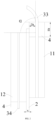
FIG. 1 is a cross-sectional view of a cell according to an embodiment of the present disclosure. -
FIG. 2 is a schematic diagram of tilting of a tab of a cell according to an embodiment of the present disclosure. - Embodiments of the present disclosure are described in detail below, and examples of the embodiments are shown in the accompanying drawings, where the same or similar elements or the elements having same or similar functions are denoted by the same or similar reference numerals throughout the description. The embodiments described below with reference to the accompanying drawings are exemplary and used only for explaining the present disclosure, and should not be construed as a limitation on the present disclosure.
- A
cell 10 in an embodiment of the present disclosure is described below with reference toFIG. 1 andFIG. 2 . Thecell 10 may be arranged in a battery. - As shown in
FIG. 1 andFIG. 2 , thecell 10 of the present disclosure includes aplate 1, aseparator 2, aninsulating support portion 4, and atab 3. Thetab 3 is connected with theplate 1. It should be noted that theplate 1 includes apositive plate 11 and anegative plate 12, and thetab 3 includes apositive tab 33 and anegative tab 34. Thepositive tab 33 is connected with thepositive plate 11, and thenegative tab 34 is connected with thenegative plate 12. The insulatingsupport portion 4 is arranged on end of theplate 1 and supports thetab 3, and thetab 3 extends through the insulatingsupport portion 4 and extends outward. The insulatingsupport portion 4 is arranged on an end of theplate 1 connected with thetab 3. That is to say, the insulatingsupport portion 4 is arranged on an end of theplate 1 through which thetab 3 is led out. It should be noted that the insulatingsupport portion 4 may be arranged on both an end of thepositive plate 11 and an end of thenegative plate 12, and thepositive tab 33 and thenegative tab 34 both may extend through the insulatingsupport portion 4 and extend outward. - As shown in
FIG. 1 , the insulatingsupport portion 4 is arranged on an upper end of thepositive plate 11 and a lower end of thenegative plate 12, an upper end of thepositive tab 33 extends through the insulatingsupport portion 4 and extends upward, and a lower end of thenegative tab 34 extends through the insulatingsupport portion 4 and extends downward. Specifically, during connection of thepositive tab 33 or thenegative tab 34 to an end cover of the battery, for example, during connection of thepositive tab 33 to the end cover of the battery, the insulatingsupport portion 4 can support thetab 3 when thetab 3 is bent. In addition, after thetab 3 is connected to the end cover and the battery is formed, the insulatingsupport portion 4 supports thetab 3. Compared with the related art, thetab 3 is not seriously tilted, and thetab 3 does not excessively squeeze theseparator 2. Therefore, when thecell 10 is vibrated or squeezed, the risk of damaging theseparator 2 can be reduced, and thepositive plate 11 and thenegative plate 12 are prevented from directly contacting each other. In this way, the risk of a short circuit inside thecell 10 can be reduced, thereby improving the use safety of the battery.FIG. 1 shows a situation in which thepositive tab 33 and thenegative tab 34 are led out through different sides. That is to say, thepositive tab 33 is led out upward, and thenegative tab 34 is led out downward. It may be understood that thepositive tab 33 and thenegative tab 34 may be led out through a same side. That is to say, thepositive tab 33 and thenegative tab 34 are both led out upward or led out downward. Regardless of how thepositive tab 33 and thenegative tab 34 are led out, the insulatingsupport portion 4 is arranged on the end of theplate 1 through which thetab 3 is led out. - The insulating
support portion 4 is arranged to support thetab 3 during connection of thetab 3 to the end cover of the battery. Therefore, thetab 3 is not seriously tilted, and thetab 3 does not squeeze theseparator 2, which can reduce the risk of damaging theseparator 2 and reduce the risk of a short circuit inside thecell 10. In this way, the use safety of the battery can be improved. - In some embodiments of the present disclosure, as shown in
FIG. 1 , thetab 3 may include atab root 31 and atab head 32. Thetab root 31 is connected with the end of theplate 1, thetab head 32 is away from the end of theplate 1. The insulatingsupport portion 4 supports thetab root 31. Thepositive tab 33 and thenegative tab 34 each may include thetab root 31 and thetab head 32. Thepositive tab 33 is used as an example for illustration. As shown inFIG. 1 , thetab root 31 is arranged below thetab head 32, thetab root 31 is connected with thetab head 32, and thetab root 31 is connected with the upper end of thepositive plate 11. During connection of thepositive tab 33 to the end cover of the battery, the insulatingsupport portion 4 supports thetab root 31, which can prevent thepositive tab 33 from being seriously tilted, and can realize a proper bending angle of thepositive tab 33, so that thepositive tab 33 can be prevented from excessively squeezing theseparator 2, theseparator 2 can be effectively prevented from being damaged, and thepositive plate 11 and thenegative plate 12 can be further prevented from directly contacting each other, thereby further improving the use safety of the battery. - In some embodiments of the present disclosure, as shown in
FIG. 1 , a cross section of the insulatingsupport portion 4 is rectangular. The rectangular insulatingsupport portion 4 can be easily coated and formed during production. It may be understood that the cross-sectional shape of the insulatingsupport portion 4 is not limited to the rectangle, and may be other shapes such as a trapezoid. A thickness of the insulatingsupport portion 4 is equal to a thickness of theplate 1. It should be noted that, at thepositive plate 11, in a left-right direction inFIG. 1 , the thickness of the insulatingsupport portion 4 is a distance between a left side surface and a right side surface of the insulatingsupport portion 4, and a value of the distance between the left side surface and the right side surface of the insulatingsupport portion 4 is equal to a value of a distance between a left side surface and a right side surface of thepositive plate 11. In an up-down direction inFIG. 1 , the left side surface of the insulatingsupport portion 4 and the left side surface of thepositive plate 11 are in a same plane, and the right side surface of the insulatingsupport portion 4 and the right side surface of thepositive plate 11 are in a same plane. Likewise, at thenegative plate 12, in the left-right direction inFIG. 1 , the thickness of the insulatingsupport portion 4 is a distance between a left side surface and a right side surface of the insulatingsupport portion 4, and a value of the distance between the left side surface and the right side surface of the insulatingsupport portion 4 is equal to a value of a distance between a left side surface and a right side surface of thenegative plate 12. In an up-down direction inFIG. 1 , the left side surface of the insulatingsupport portion 4 and the left side surface of thenegative plate 12 are in a same plane, and the right side surface of the insulatingsupport portion 4 and the right side surface of thenegative plate 12 are in a same plane. In this way, the insulatingsupport portion 4 can support thepositive tab 33 and thenegative tab 34 more effectively, and can ensure more proper bending angles of thepositive tab 33 and thenegative tab 34, so that thepositive tab 33 and thenegative tab 34 can be more effectively prevented from squashing theseparator 2, and the contact between thepositive tab 33 and thenegative plate 12 and between thenegative tab 34 and thepositive plate 11 can be further prevented, thereby further reducing the risk of a short circuit of thecell 10. - In some embodiments of the present disclosure, as shown in
FIG. 1 , the insulatingsupport portion 4 is arranged on an end of thepositive plate 11, and a free end surface of the insulatingsupport portion 4 exceeds an end surface on a same side of theseparator 2. The insulatingsupport portion 4 is arranged on the upper end of thepositive plate 11, and an upper end surface of the insulatingsupport portion 4 exceeds an upper end surface of theseparator 2. In this way, when thepositive tab 33 is bent, thepositive tab 33 can be separated from theseparator 2, so that thepositive tab 33 can be prevented from squeezing theseparator 2, and theseparator 2 can be further prevented from being damaged, thereby ensuring the insulation performance of theseparator 2. - In some embodiments of the present disclosure, as shown in
FIG. 1 , a height Ht of the insulatingsupport portion 4 configured to support the tab 3 (that is, the positive tab 33) connected with thepositive plate 11, a thickness Dt of the insulatingsupport portion 4, a bending angle α of thetab 3, and a thickness x of theseparator 2 satisfy: Ht ≥ (100 µm + x - Dt)/cosα. A height direction of the insulatingsupport portion 4 is the up-down direction inFIG. 1 , and a thickness direction of the insulatingsupport portion 4 is the left-right direction inFIG. 1 . The thickness x of theseparator 2 can satisfy: 4 µm ≤ x ≤ 40 µm. In this way, after thepositive tab 33 is bent, a proper bending angle of thepositive tab 33 can be realized, so that thetab 3 can be further prevented from squeezing theseparator 2, the risk of damaging theseparator 2 can be further reduced when thecell 10 is vibrated or squeezed, and thepositive plate 11 and thenegative plate 12 can be further prevented from directly contacting each other. Therefore, the risk of a short circuit inside thecell 10 can be further reduced, thereby improving the use safety of the battery. - In some embodiments of the present disclosure, Ht, Dt, and x further satisfy: 10 mm ≥ Ht ≥ 2 (100 µm + x - Dt). In this way, a proper bending angle of the
positive tab 33 can be realized, so that theelectrode tab 3 can be further prevented from squeezing theseparator 2, the risk of damaging theseparator 2 can be further reduced, and thepositive plate 11 and thenegative plate 12 can be effectively prevented from directly contacting each other. Therefore, the risk of a short circuit inside thecell 10 can be further reduced, thereby effectively improving the use safety of the battery. The height relation design for the insulatingsupport portion 4 can not only realize support for the tab, but also ensure the arrangement of the insulating support portion at the tab root to avoid a short circuit, thereby realizing more effective insulation. - In some embodiments of the present disclosure, as shown in
FIG. 1 , a height Ht of the insulatingsupport portion 4 configured to support the tab 3 (the negative tab 34) connected with thenegative plate 12 satisfies: 1 mm ≤ Ht ≤ 10 mm. A height direction of the insulatingsupport portion 4 is the up-down direction inFIG. 1 . In this way, the structural strength of the end of thenegative plate 12 can be ensured, so that thepositive plate 11 and thenegative plate 12 can be prevented from tilting when thetab 3 is bent. Therefore, the state of thetab 3 upon lead-out can be ensured, and the wear of theseparator 2 can be avoided, thereby ensuring the insulation between thepositive plate 11 and thenegative plate 12. - In an embodiment of the present disclosure, as shown in
FIG. 1 , a thickness Dt of the insulatingsupport portion 4 satisfies: 4 µm ≤ Dt ≤ 100 µm. The thickness design for the insulatingsupport portion 4 can realize effective support thetab 3 and prevent a short circuit as a result of tilting and squeezing of the tab. - In some embodiments of the present disclosure, the insulating
support portion 4 is attached face-to-face to an end surface of theplate 1. It should be noted that, as shown inFIG. 1 , the insulatingsupport portion 4 is attached face-to-face to the upper end of thepositive plate 11, and the insulatingsupport portion 4 is attached face-to-face to the lower end of thenegative plate 12. In this way, the insulatingsupport portion 4 can be reliably mounted to the end of theplate 1, the insulatingsupport portion 4 can stably support theelectrode tab 3, and the insulatingsupport portion 4 can be arranged more properly. - In some embodiments of the present disclosure, the insulating
support portion 4 may be configured as an inorganic salt support portion or a heat-resistant polymer support portion. When the insulatingsupport portion 4 is configured as the inorganic salt support portion, the insulatingsupport portion 4 may be configured as aluminum oxide, aluminum hydroxide, silicon oxide, silicon hydroxide, magnesium oxide, or magnesium hydroxide. The insulatingsupport portion 4 may alternatively be configured as salts of nitrogen, sulfur, or phosphorus. When the insulatingsupport portion 4 is configured as the heat-resistant polymer support portion, the insulatingsupport portion 4 may be configured as aramid extremely heat-resistant polymer materials such as a polyimide film (PI), polyethylene terephthalate (PET, which is a thermoplastic polyester), or polybutylene terephthalate (PBT). In this way, thermal deformation of the insulatingsupport portion 4 can be prevented, and the structural strength of the insulatingsupport portion 4 can be ensured, so that the insulatingsupport portion 4 can reliably support thetab 3, thereby ensuring the operating reliability of thecell 10. - The battery in this embodiment of the present disclosure includes the
cell 10 in the above embodiment, and thecell 10 is arranged in the battery. The insulatingsupport portion 4 supports thetab 3 during connection of thetab 3 to an end cover of the battery. Therefore, thetab 3 is not seriously tilted, and thetab 3 does not squeeze theseparator 2, which can reduce the risk of damaging theseparator 2 and reduce the risk of a short circuit inside thecell 10. In this way, the use safety of the battery can be improved. - In the descriptions of the present disclosure, descriptions using reference terms "an embodiment", "some embodiments", "an exemplary embodiment", "an example", "a specific example", or "some examples" mean that specific characteristics, structures, materials, or features described with reference to the embodiment or example are included in at least one embodiment or example of the present disclosure. In the present disclosure, schematic descriptions of the foregoing terms do not necessarily point at a same embodiment or example. In addition, the described specific features, structures, materials, or characteristics may be combined in a proper manner in any one or more of the embodiments or examples.
- Although the embodiments of the present disclosure are shown and described, a person of ordinary skill in the art may understand that various changes, modifications, replacements and variations may be made to the embodiments without departing from the principles and spirit of the present disclosure, and the scope of the present disclosure is as defined by the appended claims and their equivalents.
Claims (20)
- A cell, comprising:a plate, a separator, and a tab, wherein the tab is connected with the plate; andan insulating support portion, arranged on an end of the plate and supporting the tab, wherein the tab extends through the insulating support portion and extends outward.
- The cell according to claim 1, wherein the tab comprises a tab root and a tab head; the tab root is connected with the end of the plate; the tab head is away from the end of the plate; and the insulating support portion supports the tab root.
- The cell according to claim 1 or 2, wherein a thickness of the insulating support portion is equal to a thickness of the plate.
- The cell according to any of claims 1 to 3, wherein the plate comprises a positive plate; the insulating support portion is arranged on an end of the positive plate; and a free end surface of the insulating support portion exceeds an end surface on a same side of the separator.
- The cell according to claim 4, wherein the tab comprises a positive tab connected with the positive plate; and the positive plate extends through the insulating support portion and extends outward.
- The cell according to claim 5, wherein the plate further comprises a negative plate; the tab further comprises a negative tab connected with the negative plate; the insulating support portion is arranged on an end of the negative plate; and the negative plate extends through the insulating support portion and extends outward.
- The cell according to claim 6, wherein the positive tab and the negative tab are led out through a same side of the cell.
- The cell according to claim 6, wherein the positive tab and the negative tab are led out through different sides of the cell.
- The cell according to claim 4, wherein a height Ht of the insulating support portion configured to support the tab connected with the positive plate, a thickness Dt of the insulating support portion between the separator and the tab connected with the positive plate, a bending angle α of the tab, and a thickness x of the separator satisfy: Ht ≥ (100 µm + x - Dt)/cosα.
- The cell according to claim 4 or 9, wherein Ht, Dt, and x satisfy: 10 mm ≥ Ht ≥ 2 (100 µm + x - Dt).
- The cell according to claim 1, wherein the plate comprises a negative plate; and a height Ht of the insulating support portion configured to support the tab connected with the negative plate satisfies: 1 mm ≤ Ht ≤ 10 mm.
- The cell according to claim 1, wherein the insulating support portion is attached face-to-face to the end of the plate.
- The cell according to claim 1, wherein a thickness Dt of the insulating support portion between the separator and the tab satisfies: 4 µm ≤ Dt ≤ 100 µm.
- The cell according to any of claims 1 to 13, wherein the thickness x of the separator satisfies: 4 µm ≤ x ≤ 40 µm.
- The cell according to any of claims 1 to 14, wherein the insulating support portion is configured as an inorganic salt support portion.
- The cell according to claim 15, wherein the inorganic salt support portion is made of aluminum oxide, aluminum hydroxide, silicon oxide, silicon hydroxide, magnesium oxide, or magnesium hydroxide.
- The cell according to any of claims 1 to 14, wherein the insulating support portion is configured as a heat-resistant polymer support portion.
- The cell according to claim 17, wherein the heat-resistant polymer support portion is made of a polyimide (PI) film, a thermoplastic polyester, or polybutylene terephthalate (PBT).
- The cell according to any of claims 1 to 18, wherein a cross section of the insulating support portion is rectangular.
- A battery, comprising the cell according to any of claims 1 to 19.
Applications Claiming Priority (2)
| Application Number | Priority Date | Filing Date | Title |
|---|---|---|---|
| CN202010614979.7A CN113948825B (en) | 2020-06-30 | 2020-06-30 | Battery cell and battery |
| PCT/CN2021/103450 WO2022002113A1 (en) | 2020-06-30 | 2021-06-30 | Battery cell and battery |
Publications (2)
| Publication Number | Publication Date |
|---|---|
| EP4175052A1 true EP4175052A1 (en) | 2023-05-03 |
| EP4175052A4 EP4175052A4 (en) | 2024-10-02 |
Family
ID=79317513
Family Applications (1)
| Application Number | Title | Priority Date | Filing Date |
|---|---|---|---|
| EP21831990.3A Pending EP4175052A4 (en) | 2020-06-30 | 2021-06-30 | BATTERY ELEMENT AND BATTERY |
Country Status (7)
| Country | Link |
|---|---|
| US (1) | US20230118034A1 (en) |
| EP (1) | EP4175052A4 (en) |
| JP (1) | JP7813764B2 (en) |
| KR (1) | KR102925122B1 (en) |
| CN (1) | CN113948825B (en) |
| CA (1) | CA3180347A1 (en) |
| WO (1) | WO2022002113A1 (en) |
Families Citing this family (2)
| Publication number | Priority date | Publication date | Assignee | Title |
|---|---|---|---|---|
| CN115911256A (en) * | 2022-11-04 | 2023-04-04 | 厦门新能达科技有限公司 | Cylindrical battery and electrical device containing it |
| CN117039362A (en) * | 2023-09-07 | 2023-11-10 | 宁德新能源科技有限公司 | Secondary batteries and electronic devices |
Family Cites Families (13)
| Publication number | Priority date | Publication date | Assignee | Title |
|---|---|---|---|---|
| JP4366783B2 (en) * | 1998-11-16 | 2009-11-18 | 株式会社デンソー | Multilayer battery and method of manufacturing electrode thereof |
| JP4592297B2 (en) * | 2004-02-09 | 2010-12-01 | 株式会社東芝 | Sealed battery |
| JPWO2011013300A1 (en) * | 2009-07-31 | 2013-01-07 | パナソニック株式会社 | Non-aqueous electrolyte secondary battery and manufacturing method thereof |
| EP2573857B1 (en) * | 2010-05-18 | 2016-03-02 | Toyota Jidosha Kabushiki Kaisha | Nonaqueous electrolyte secondary battery, vehicle, and device using battery |
| JP5844052B2 (en) * | 2011-02-04 | 2016-01-13 | 三洋電機株式会社 | Multilayer battery and method for manufacturing the same |
| JP6006104B2 (en) * | 2012-02-29 | 2016-10-12 | 昭和電工パッケージング株式会社 | Tab lead manufacturing method |
| CN202695572U (en) * | 2012-07-09 | 2013-01-23 | 深圳市豪鹏科技有限公司 | Sealing ring and nickel-hydrogen battery using same |
| CN106159179B (en) * | 2015-04-21 | 2018-12-04 | 宁德时代新能源科技股份有限公司 | Metal lithium battery |
| JP6601065B2 (en) * | 2015-08-31 | 2019-11-06 | 日本電気株式会社 | Secondary battery |
| CN210156498U (en) * | 2019-04-28 | 2020-03-17 | 天能帅福得能源股份有限公司 | Cylindrical battery |
| CN209981386U (en) * | 2019-04-30 | 2020-01-21 | 宁德时代新能源科技股份有限公司 | Electrode assembly and secondary battery thereof |
| CN210535760U (en) * | 2019-08-14 | 2020-05-15 | 宁德时代新能源科技股份有限公司 | Electrode assemblies and secondary batteries |
| CN111326699B (en) * | 2019-08-14 | 2021-11-09 | 宁德时代新能源科技股份有限公司 | Secondary battery |
-
2020
- 2020-06-30 CN CN202010614979.7A patent/CN113948825B/en active Active
-
2021
- 2021-06-30 EP EP21831990.3A patent/EP4175052A4/en active Pending
- 2021-06-30 WO PCT/CN2021/103450 patent/WO2022002113A1/en not_active Ceased
- 2021-06-30 CA CA3180347A patent/CA3180347A1/en active Pending
- 2021-06-30 JP JP2023500020A patent/JP7813764B2/en active Active
- 2021-06-30 KR KR1020237003471A patent/KR102925122B1/en active Active
-
2022
- 2022-12-19 US US18/084,055 patent/US20230118034A1/en active Pending
Also Published As
| Publication number | Publication date |
|---|---|
| CA3180347A1 (en) | 2022-01-06 |
| US20230118034A1 (en) | 2023-04-20 |
| KR102925122B1 (en) | 2026-02-10 |
| EP4175052A4 (en) | 2024-10-02 |
| WO2022002113A1 (en) | 2022-01-06 |
| KR20230031342A (en) | 2023-03-07 |
| CN113948825A (en) | 2022-01-18 |
| JP7813764B2 (en) | 2026-02-13 |
| CN113948825B (en) | 2023-09-05 |
| JP2023532357A (en) | 2023-07-27 |
Similar Documents
| Publication | Publication Date | Title |
|---|---|---|
| US20230118034A1 (en) | Battery core and battery | |
| JP5318839B2 (en) | Battery | |
| KR101015834B1 (en) | Battery module | |
| EP2595214B1 (en) | Rechargeable battery | |
| KR20100102542A (en) | Rechargeable battery | |
| CN107302062B (en) | Secondary battery | |
| CN120184500A (en) | Secondary batteries and automobiles | |
| US20240162541A1 (en) | Electrochemical apparatus and electric apparatus | |
| CN106920903A (en) | Secondary cell | |
| US10153478B2 (en) | Secondary battery | |
| CN1960027A (en) | Sealed squareness battery | |
| US12567658B2 (en) | Secondary battery | |
| CN209401762U (en) | Secondary batteries and battery modules | |
| CN215644696U (en) | Battery cover plate assembly and battery | |
| CN213150880U (en) | Secondary battery | |
| JP5650567B2 (en) | Flat battery and sealed can | |
| US20240128602A1 (en) | Current collector assembly, battery cell, and battery pack | |
| EP3531478B1 (en) | Current blocking structure applied to pouch type secondary battery | |
| CN222106861U (en) | Battery and battery pack | |
| CN120149719B (en) | A single battery and a battery pack | |
| CN218039501U (en) | Top cover assembly and battery | |
| EP4336647A1 (en) | Connecting member, battery cell and battery pack | |
| EP4510324A1 (en) | Secondary battery | |
| CN222146529U (en) | Insulating gasket and battery | |
| US20230061623A1 (en) | Power storage device |
Legal Events
| Date | Code | Title | Description |
|---|---|---|---|
| STAA | Information on the status of an ep patent application or granted ep patent |
Free format text: STATUS: THE INTERNATIONAL PUBLICATION HAS BEEN MADE |
|
| PUAI | Public reference made under article 153(3) epc to a published international application that has entered the european phase |
Free format text: ORIGINAL CODE: 0009012 |
|
| STAA | Information on the status of an ep patent application or granted ep patent |
Free format text: STATUS: REQUEST FOR EXAMINATION WAS MADE |
|
| 17P | Request for examination filed |
Effective date: 20230118 |
|
| AK | Designated contracting states |
Kind code of ref document: A1 Designated state(s): AL AT BE BG CH CY CZ DE DK EE ES FI FR GB GR HR HU IE IS IT LI LT LU LV MC MK MT NL NO PL PT RO RS SE SI SK SM TR |
|
| DAV | Request for validation of the european patent (deleted) | ||
| DAX | Request for extension of the european patent (deleted) | ||
| REG | Reference to a national code |
Ref country code: DE Ref legal event code: R079 Free format text: PREVIOUS MAIN CLASS: H01M0050572000 Ipc: H01M0004020000 |
|
| A4 | Supplementary search report drawn up and despatched |
Effective date: 20240903 |
|
| RIC1 | Information provided on ipc code assigned before grant |
Ipc: H01M 50/595 20210101ALI20240828BHEP Ipc: H01M 50/59 20210101ALI20240828BHEP Ipc: H01M 50/586 20210101ALI20240828BHEP Ipc: H01M 50/531 20210101ALI20240828BHEP Ipc: H01M 4/04 20060101ALI20240828BHEP Ipc: H01M 4/02 20060101AFI20240828BHEP |