EP4175048A1 - Cell lead-out piece, battery, and electric vehicle - Google Patents
Cell lead-out piece, battery, and electric vehicle Download PDFInfo
- Publication number
- EP4175048A1 EP4175048A1 EP21831959.8A EP21831959A EP4175048A1 EP 4175048 A1 EP4175048 A1 EP 4175048A1 EP 21831959 A EP21831959 A EP 21831959A EP 4175048 A1 EP4175048 A1 EP 4175048A1
- Authority
- EP
- European Patent Office
- Prior art keywords
- heat
- cell lead
- out sheet
- conducting member
- sheet according
- Prior art date
- Legal status (The legal status is an assumption and is not a legal conclusion. Google has not performed a legal analysis and makes no representation as to the accuracy of the status listed.)
- Pending
Links
Images


Classifications
-
- B—PERFORMING OPERATIONS; TRANSPORTING
- B23—MACHINE TOOLS; METAL-WORKING NOT OTHERWISE PROVIDED FOR
- B23K—SOLDERING OR UNSOLDERING; WELDING; CLADDING OR PLATING BY SOLDERING OR WELDING; CUTTING BY APPLYING HEAT LOCALLY, e.g. FLAME CUTTING; WORKING BY LASER BEAM
- B23K20/00—Non-electric welding by applying impact or other pressure, with or without the application of heat, e.g. cladding or plating
- B23K20/10—Non-electric welding by applying impact or other pressure, with or without the application of heat, e.g. cladding or plating making use of vibrations, e.g. ultrasonic welding
-
- H—ELECTRICITY
- H01—ELECTRIC ELEMENTS
- H01M—PROCESSES OR MEANS, e.g. BATTERIES, FOR THE DIRECT CONVERSION OF CHEMICAL ENERGY INTO ELECTRICAL ENERGY
- H01M10/00—Secondary cells; Manufacture thereof
- H01M10/60—Heating or cooling; Temperature control
- H01M10/65—Means for temperature control structurally associated with the cells
- H01M10/654—Means for temperature control structurally associated with the cells located inside the innermost case of the cells, e.g. mandrels, electrodes or electrolytes
-
- B—PERFORMING OPERATIONS; TRANSPORTING
- B23—MACHINE TOOLS; METAL-WORKING NOT OTHERWISE PROVIDED FOR
- B23K—SOLDERING OR UNSOLDERING; WELDING; CLADDING OR PLATING BY SOLDERING OR WELDING; CUTTING BY APPLYING HEAT LOCALLY, e.g. FLAME CUTTING; WORKING BY LASER BEAM
- B23K26/00—Working by laser beam, e.g. welding, cutting or boring
- B23K26/20—Bonding
- B23K26/21—Bonding by welding
-
- B—PERFORMING OPERATIONS; TRANSPORTING
- B60—VEHICLES IN GENERAL
- B60L—PROPULSION OF ELECTRICALLY-PROPELLED VEHICLES; SUPPLYING ELECTRIC POWER FOR AUXILIARY EQUIPMENT OF ELECTRICALLY-PROPELLED VEHICLES; ELECTRODYNAMIC BRAKE SYSTEMS FOR VEHICLES IN GENERAL; MAGNETIC SUSPENSION OR LEVITATION FOR VEHICLES; MONITORING OPERATING VARIABLES OF ELECTRICALLY-PROPELLED VEHICLES; ELECTRIC SAFETY DEVICES FOR ELECTRICALLY-PROPELLED VEHICLES
- B60L50/00—Electric propulsion with power supplied within the vehicle
- B60L50/50—Electric propulsion with power supplied within the vehicle using propulsion power supplied by batteries or fuel cells
- B60L50/60—Electric propulsion with power supplied within the vehicle using propulsion power supplied by batteries or fuel cells using power supplied by batteries
- B60L50/64—Constructional details of batteries specially adapted for electric vehicles
-
- B—PERFORMING OPERATIONS; TRANSPORTING
- B60—VEHICLES IN GENERAL
- B60L—PROPULSION OF ELECTRICALLY-PROPELLED VEHICLES; SUPPLYING ELECTRIC POWER FOR AUXILIARY EQUIPMENT OF ELECTRICALLY-PROPELLED VEHICLES; ELECTRODYNAMIC BRAKE SYSTEMS FOR VEHICLES IN GENERAL; MAGNETIC SUSPENSION OR LEVITATION FOR VEHICLES; MONITORING OPERATING VARIABLES OF ELECTRICALLY-PROPELLED VEHICLES; ELECTRIC SAFETY DEVICES FOR ELECTRICALLY-PROPELLED VEHICLES
- B60L58/00—Methods or circuit arrangements for monitoring or controlling batteries or fuel cells, specially adapted for electric vehicles
- B60L58/10—Methods or circuit arrangements for monitoring or controlling batteries or fuel cells, specially adapted for electric vehicles for monitoring or controlling batteries
- B60L58/24—Methods or circuit arrangements for monitoring or controlling batteries or fuel cells, specially adapted for electric vehicles for monitoring or controlling batteries for controlling the temperature of batteries
- B60L58/26—Methods or circuit arrangements for monitoring or controlling batteries or fuel cells, specially adapted for electric vehicles for monitoring or controlling batteries for controlling the temperature of batteries by cooling
-
- H—ELECTRICITY
- H01—ELECTRIC ELEMENTS
- H01M—PROCESSES OR MEANS, e.g. BATTERIES, FOR THE DIRECT CONVERSION OF CHEMICAL ENERGY INTO ELECTRICAL ENERGY
- H01M10/00—Secondary cells; Manufacture thereof
- H01M10/60—Heating or cooling; Temperature control
- H01M10/61—Types of temperature control
- H01M10/613—Cooling or keeping cold
-
- H—ELECTRICITY
- H01—ELECTRIC ELEMENTS
- H01M—PROCESSES OR MEANS, e.g. BATTERIES, FOR THE DIRECT CONVERSION OF CHEMICAL ENERGY INTO ELECTRICAL ENERGY
- H01M10/00—Secondary cells; Manufacture thereof
- H01M10/60—Heating or cooling; Temperature control
- H01M10/62—Heating or cooling; Temperature control specially adapted for specific applications
- H01M10/625—Vehicles
-
- H—ELECTRICITY
- H01—ELECTRIC ELEMENTS
- H01M—PROCESSES OR MEANS, e.g. BATTERIES, FOR THE DIRECT CONVERSION OF CHEMICAL ENERGY INTO ELECTRICAL ENERGY
- H01M10/00—Secondary cells; Manufacture thereof
- H01M10/60—Heating or cooling; Temperature control
- H01M10/64—Heating or cooling; Temperature control characterised by the shape of the cells
- H01M10/647—Prismatic or flat cells, e.g. pouch cells
-
- H—ELECTRICITY
- H01—ELECTRIC ELEMENTS
- H01M—PROCESSES OR MEANS, e.g. BATTERIES, FOR THE DIRECT CONVERSION OF CHEMICAL ENERGY INTO ELECTRICAL ENERGY
- H01M10/00—Secondary cells; Manufacture thereof
- H01M10/60—Heating or cooling; Temperature control
- H01M10/65—Means for temperature control structurally associated with the cells
- H01M10/653—Means for temperature control structurally associated with the cells characterised by electrically insulating or thermally conductive materials
-
- H—ELECTRICITY
- H01—ELECTRIC ELEMENTS
- H01M—PROCESSES OR MEANS, e.g. BATTERIES, FOR THE DIRECT CONVERSION OF CHEMICAL ENERGY INTO ELECTRICAL ENERGY
- H01M10/00—Secondary cells; Manufacture thereof
- H01M10/60—Heating or cooling; Temperature control
- H01M10/65—Means for temperature control structurally associated with the cells
- H01M10/655—Solid structures for heat exchange or heat conduction
- H01M10/6551—Surfaces specially adapted for heat dissipation or radiation, e.g. fins or coatings
-
- H—ELECTRICITY
- H01—ELECTRIC ELEMENTS
- H01M—PROCESSES OR MEANS, e.g. BATTERIES, FOR THE DIRECT CONVERSION OF CHEMICAL ENERGY INTO ELECTRICAL ENERGY
- H01M10/00—Secondary cells; Manufacture thereof
- H01M10/60—Heating or cooling; Temperature control
- H01M10/65—Means for temperature control structurally associated with the cells
- H01M10/655—Solid structures for heat exchange or heat conduction
- H01M10/6553—Terminals or leads
-
- H—ELECTRICITY
- H01—ELECTRIC ELEMENTS
- H01M—PROCESSES OR MEANS, e.g. BATTERIES, FOR THE DIRECT CONVERSION OF CHEMICAL ENERGY INTO ELECTRICAL ENERGY
- H01M10/00—Secondary cells; Manufacture thereof
- H01M10/60—Heating or cooling; Temperature control
- H01M10/65—Means for temperature control structurally associated with the cells
- H01M10/655—Solid structures for heat exchange or heat conduction
- H01M10/6554—Rods or plates
-
- H—ELECTRICITY
- H01—ELECTRIC ELEMENTS
- H01M—PROCESSES OR MEANS, e.g. BATTERIES, FOR THE DIRECT CONVERSION OF CHEMICAL ENERGY INTO ELECTRICAL ENERGY
- H01M10/00—Secondary cells; Manufacture thereof
- H01M10/60—Heating or cooling; Temperature control
- H01M10/65—Means for temperature control structurally associated with the cells
- H01M10/655—Solid structures for heat exchange or heat conduction
- H01M10/6556—Solid parts with flow channel passages or pipes for heat exchange
-
- H—ELECTRICITY
- H01—ELECTRIC ELEMENTS
- H01M—PROCESSES OR MEANS, e.g. BATTERIES, FOR THE DIRECT CONVERSION OF CHEMICAL ENERGY INTO ELECTRICAL ENERGY
- H01M50/00—Constructional details or processes of manufacture of the non-active parts of electrochemical cells other than fuel cells, e.g. hybrid cells
- H01M50/50—Current conducting connections for cells or batteries
- H01M50/531—Electrode connections inside a battery casing
- H01M50/533—Electrode connections inside a battery casing characterised by the shape of the leads or tabs
-
- H—ELECTRICITY
- H01—ELECTRIC ELEMENTS
- H01M—PROCESSES OR MEANS, e.g. BATTERIES, FOR THE DIRECT CONVERSION OF CHEMICAL ENERGY INTO ELECTRICAL ENERGY
- H01M50/00—Constructional details or processes of manufacture of the non-active parts of electrochemical cells other than fuel cells, e.g. hybrid cells
- H01M50/50—Current conducting connections for cells or batteries
- H01M50/531—Electrode connections inside a battery casing
- H01M50/534—Electrode connections inside a battery casing characterised by the material of the leads or tabs
-
- H—ELECTRICITY
- H01—ELECTRIC ELEMENTS
- H01M—PROCESSES OR MEANS, e.g. BATTERIES, FOR THE DIRECT CONVERSION OF CHEMICAL ENERGY INTO ELECTRICAL ENERGY
- H01M50/00—Constructional details or processes of manufacture of the non-active parts of electrochemical cells other than fuel cells, e.g. hybrid cells
- H01M50/50—Current conducting connections for cells or batteries
- H01M50/531—Electrode connections inside a battery casing
- H01M50/536—Electrode connections inside a battery casing characterised by the method of fixing the leads to the electrodes, e.g. by welding
-
- H—ELECTRICITY
- H01—ELECTRIC ELEMENTS
- H01M—PROCESSES OR MEANS, e.g. BATTERIES, FOR THE DIRECT CONVERSION OF CHEMICAL ENERGY INTO ELECTRICAL ENERGY
- H01M50/00—Constructional details or processes of manufacture of the non-active parts of electrochemical cells other than fuel cells, e.g. hybrid cells
- H01M50/50—Current conducting connections for cells or batteries
- H01M50/543—Terminals
- H01M50/547—Terminals characterised by the disposition of the terminals on the cells
- H01M50/548—Terminals characterised by the disposition of the terminals on the cells on opposite sides of the cell
-
- H—ELECTRICITY
- H01—ELECTRIC ELEMENTS
- H01M—PROCESSES OR MEANS, e.g. BATTERIES, FOR THE DIRECT CONVERSION OF CHEMICAL ENERGY INTO ELECTRICAL ENERGY
- H01M50/00—Constructional details or processes of manufacture of the non-active parts of electrochemical cells other than fuel cells, e.g. hybrid cells
- H01M50/50—Current conducting connections for cells or batteries
- H01M50/543—Terminals
- H01M50/547—Terminals characterised by the disposition of the terminals on the cells
- H01M50/55—Terminals characterised by the disposition of the terminals on the cells on the same side of the cell
-
- H—ELECTRICITY
- H01—ELECTRIC ELEMENTS
- H01M—PROCESSES OR MEANS, e.g. BATTERIES, FOR THE DIRECT CONVERSION OF CHEMICAL ENERGY INTO ELECTRICAL ENERGY
- H01M50/00—Constructional details or processes of manufacture of the non-active parts of electrochemical cells other than fuel cells, e.g. hybrid cells
- H01M50/50—Current conducting connections for cells or batteries
- H01M50/543—Terminals
- H01M50/552—Terminals characterised by their shape
- H01M50/553—Terminals adapted for prismatic, pouch or rectangular cells
-
- H—ELECTRICITY
- H01—ELECTRIC ELEMENTS
- H01M—PROCESSES OR MEANS, e.g. BATTERIES, FOR THE DIRECT CONVERSION OF CHEMICAL ENERGY INTO ELECTRICAL ENERGY
- H01M50/00—Constructional details or processes of manufacture of the non-active parts of electrochemical cells other than fuel cells, e.g. hybrid cells
- H01M50/50—Current conducting connections for cells or batteries
- H01M50/572—Means for preventing undesired use or discharge
- H01M50/584—Means for preventing undesired use or discharge for preventing incorrect connections inside or outside the batteries
- H01M50/59—Means for preventing undesired use or discharge for preventing incorrect connections inside or outside the batteries characterised by the protection means
- H01M50/593—Spacers; Insulating plates
-
- B—PERFORMING OPERATIONS; TRANSPORTING
- B23—MACHINE TOOLS; METAL-WORKING NOT OTHERWISE PROVIDED FOR
- B23K—SOLDERING OR UNSOLDERING; WELDING; CLADDING OR PLATING BY SOLDERING OR WELDING; CUTTING BY APPLYING HEAT LOCALLY, e.g. FLAME CUTTING; WORKING BY LASER BEAM
- B23K2101/00—Articles made by soldering, welding or cutting
- B23K2101/36—Electric or electronic devices
-
- B—PERFORMING OPERATIONS; TRANSPORTING
- B60—VEHICLES IN GENERAL
- B60L—PROPULSION OF ELECTRICALLY-PROPELLED VEHICLES; SUPPLYING ELECTRIC POWER FOR AUXILIARY EQUIPMENT OF ELECTRICALLY-PROPELLED VEHICLES; ELECTRODYNAMIC BRAKE SYSTEMS FOR VEHICLES IN GENERAL; MAGNETIC SUSPENSION OR LEVITATION FOR VEHICLES; MONITORING OPERATING VARIABLES OF ELECTRICALLY-PROPELLED VEHICLES; ELECTRIC SAFETY DEVICES FOR ELECTRICALLY-PROPELLED VEHICLES
- B60L2240/00—Control parameters of input or output; Target parameters
- B60L2240/40—Drive Train control parameters
- B60L2240/54—Drive Train control parameters related to batteries
- B60L2240/545—Temperature
-
- H—ELECTRICITY
- H01—ELECTRIC ELEMENTS
- H01M—PROCESSES OR MEANS, e.g. BATTERIES, FOR THE DIRECT CONVERSION OF CHEMICAL ENERGY INTO ELECTRICAL ENERGY
- H01M2220/00—Batteries for particular applications
- H01M2220/20—Batteries in motive systems, e.g. vehicle, ship, plane
-
- Y—GENERAL TAGGING OF NEW TECHNOLOGICAL DEVELOPMENTS; GENERAL TAGGING OF CROSS-SECTIONAL TECHNOLOGIES SPANNING OVER SEVERAL SECTIONS OF THE IPC; TECHNICAL SUBJECTS COVERED BY FORMER USPC CROSS-REFERENCE ART COLLECTIONS [XRACs] AND DIGESTS
- Y02—TECHNOLOGIES OR APPLICATIONS FOR MITIGATION OR ADAPTATION AGAINST CLIMATE CHANGE
- Y02E—REDUCTION OF GREENHOUSE GAS [GHG] EMISSIONS, RELATED TO ENERGY GENERATION, TRANSMISSION OR DISTRIBUTION
- Y02E60/00—Enabling technologies; Technologies with a potential or indirect contribution to GHG emissions mitigation
- Y02E60/10—Energy storage using batteries
-
- Y—GENERAL TAGGING OF NEW TECHNOLOGICAL DEVELOPMENTS; GENERAL TAGGING OF CROSS-SECTIONAL TECHNOLOGIES SPANNING OVER SEVERAL SECTIONS OF THE IPC; TECHNICAL SUBJECTS COVERED BY FORMER USPC CROSS-REFERENCE ART COLLECTIONS [XRACs] AND DIGESTS
- Y02—TECHNOLOGIES OR APPLICATIONS FOR MITIGATION OR ADAPTATION AGAINST CLIMATE CHANGE
- Y02T—CLIMATE CHANGE MITIGATION TECHNOLOGIES RELATED TO TRANSPORTATION
- Y02T10/00—Road transport of goods or passengers
- Y02T10/60—Other road transportation technologies with climate change mitigation effect
- Y02T10/70—Energy storage systems for electromobility, e.g. batteries
Definitions
- the present application relates to the field of electric vehicles, and specifically to a cell lead-out sheet, a battery and an electric vehicle.
- HEV/mHEV batteries have high requirements for power performance, and inevitably need to be frequently charged and discharged at high rates, which leads to the generation of a large amount of heat by the battery. Consequently, several problems arise. (1) The generation of a large amount of heat leads to accelerated battery deterioration and reduced cycle/storage life. (2) The accumulation of heat makes it difficult to dissipate the heat, which may result in safety risks. (3) The poor thermal conductivity of the battery requires external liquid cooling, which brings about the problems of high energy consumption and high carbon emissions. How to improve the heat dissipation performance of the battery has now become the main problem to be solved in terms of battery design.
- the present application provides a cell lead-out sheet with good heat dissipation performance.
- the heat dissipation performance of the cell lead-out sheet is improved by arranging a heat-conducting member at an installation gap between two extending branches of the cell lead-out sheet.
- the present application provides a cell lead-out sheet, including a heat-conducting member, a main body, and two extending branches bent and extending from one end of the main body, where the main body is configured to electrically connect a positive terminal and/or a negative terminal of a battery, the two extending branches are respectively configured to electrically connect to tabs of an electrode core in the battery, the two extending branches are spaced apart from each other to form an installation gap, the heat-conducting member is arranged on a side of the two extending branches facing away from the electrode core, and the heat-conducting member at least partially covers the installation gap.
- the electrode core is formed by winding a positive electrode plate, a separator and a negative electrode plate.
- Tabs respectively extending from the positive and negative electrode plates for conducting current are arranged on two sides of the wound electrode core.
- a plurality of tabs are press-fit to form an all-tab design, and the press-fit tabs are electrically connected to the positive terminal and/or the negative terminal outside the housing through the cell lead-out sheets.
- the electrical connection between the cell lead-out sheet and the tab is achieved by welding the two extending branches to two sides of the tab.
- the two extending branches need to be spaced apart, so as to form the installation gap.
- the installation gap is used for battery assembly.
- the heat-conducting element is arranged on the side of the installation gap facing away from the electrode core.
- the heat dissipation area of the cell lead-out sheet is increased through the heat-conducting member, thereby improving the heat dissipation effect of the cell lead-out sheet.
- the heat-conducting member may be a heat dissipation sheet, a heat dissipation net, or other structures capable of dissipating heat, which is not particularly limited herein.
- the arrangement of the heat dissipation sheet in the installation gap is a reasonable utilization of the structure of the space, and increases the heat dissipation area of the cell lead-out sheet and improves the heat dissipation effect without affecting the operation of the electrode core.
- the heat-conducting member completely covers the installation gap. In this embodiment, because the heat-conducting member completely covers the installation gap, the heat dissipation area of the entire cell lead-out sheet is maximized, thereby maximizing the heat dissipation effect.
- two ends of the heat-conducting member are respectively connected to the two extending branches.
- the two ends of the heat-conducting member are respectively adhered to the two extending branches.
- Various adhesion methods may be used. For example, an adhesive is applied on the two ends of the heat-conducting member, and then the two ends are adhered to the two extending branches.
- the two ends of the heat-conducting member are placed on the extending branch respectively, and then the heat-conducting member is fixed at the installation gap with an adhesive tape.
- one end of the heat-conducting member is connected to one side of the tab.
- one end of the heat-conducting member may be connected to one side of the tab by welding, and the other end of the heat-conducting member may be bent to cover the installation gap.
- an extending direction of the main body is defined as a first direction
- an extending direction of the two extending branches is defined as a second direction
- the two extending branches are spaced apart from each other in a third direction
- the first direction, the second direction, and the third direction are perpendicular to each other. Because the two extending branches are spaced apart from each other in the third direction to form the installation gap, the cell lead-out sheet can better fit the structural design of the electrode core.
- a surface of one of the extending branches fits to one side of the tab, and a surface of the other extending branch fits to another side of the tab.
- the surfaces of the two extending branches respectively fit to the two sides of the tab.
- the cell lead-out sheet further includes a connection portion located on one end of the extending branches away from the main body, where the connection portions are configured to connect the two extending branches.
- the design of the connection portions is to connect the two extending branches to ensure the stability of the structure.
- a surface of the extending branches is connected to the tab by welding.
- the welding method used herein may be ultrasonic welding or laser welding to ensure the flatness and stability of the structure.
- the extending branches are connected to the tab by ultrasonic welding or laser welding.
- the heat-conducting member is made of a metal material.
- a side spacer made of an insulating material is arranged on the tab to space the heat-conducting member apart from a housing of the battery.
- the heat-conducting member is made of thermally conductive silicone.
- the heat-conducting member is made of composite ceramic.
- the composite ceramic includes a mixture of plastic and a highly thermally conductive material.
- the heat-conducting member is a carbon-based material.
- the carbon-based material includes a heat dissipation layer and a thermally conductive insulation layer.
- the present application provides a battery, including a housing, an electrode core, and the cell lead-out sheets described above.
- the cell lead-out sheet and the electrode core are electrically connected to form an electrode core assembly.
- the electrode core assembly is received in the housing.
- the cell lead-out sheet is electrically connected to a tab of the electrode core, and the cell lead-out sheet and the electrode core are both received in the housing.
- the housing includes a lower housing and a cover plate.
- the lower housing includes a receiving space.
- the cell lead-out sheet is arranged in the receiving space.
- a positive terminal and/or a negative terminal are arranged on the cover plate.
- the tabs are connected to the positive terminal and/or the negative terminal through the cell lead-out sheets.
- the present application provides an electric vehicle, including the battery described above.
- the cell lead-out sheet of the battery has a good heat dissipation effect, which can effectively solve the heat dissipation problem during the operation of the electrode core, and prevent the electric vehicle from abnormal operation in use due to an excessively high temperature of the electrode core.
- the heat-conducting member by arranging the heat-conducting member at the installation gap between the two extending branches, the heat-dissipating area of the cell lead-out sheet is increased without affecting the operation of the cell lead-out sheet, thereby improving the heat dissipation effect.
- the present application provides a cell lead-out sheet 10.
- the cell lead-out sheet 10 may be widely used in battery assembly.
- FIG. 1 to FIG. 5 For a more detailed description of the features of the cell lead-out sheet 10 in the solution, refer to FIG. 1 to FIG. 5 .
- FIG. 1 and FIG. 2 are schematic structural diagrams showing installation of a cell lead-out sheet 10 and an electrode core 20.
- FIG. 1 is a schematic structural diagram of the cell lead-out sheet 10 with a heat-conducting member 13 being hidden.
- the cell lead-out sheet 10 includes a main body 11 and two extending branches 12 extending from the main body 11.
- the main body 11 is externally connected to a positive/negative terminal 40.
- the two extending branches 12 are respectively electrically connected to the electrode core 20.
- the two extending branches 12 are spaced apart to form an installation gap 14.
- the installation gap 14 is a space prefabricated for the subsequent welding of the cell lead-out sheet 10 and tabs 21 to facilitate placement of welding equipment.
- the heat-conducting element 13 is arranged on a side of the installation gap 14 facing away from the electrode core 20.
- the electrode core 20 in the embodiments is generally formed by winding a positive electrode plate, a separator and a negative electrode plate.
- Tabs 21 respectively extending from the positive and negative electrode plates for conducting current are arranged on two sides of the wound electrode core 20.
- a plurality of tabs 21 are press-fit to form an all-tab design, and the press-fit tabs 21 are electrically connected to the positive/negative terminal 40 outside through the cell lead-out sheets 10.
- the electrical connection between the cell lead-out sheet 10 and the tab 21 is achieved by welding the two extending branches 12 to two sides of the tab 21. As shown in FIG.
- the two extending branches 12 need to be spaced apart, so as to form the installation gap 14.
- the heat-conducting element 13 is arranged on the side of the installation gap 14 facing away from the electrode core 21, and the heat-conducting member 13 at least partially covers the installation gap 14. Therefore, the heat dissipation area of the cell lead-out sheet 10 is increased through the heat-conducting member 13, thereby improving the heat dissipation effect of the cell lead-out sheet 10.
- the heat-conducting member 13 may be a heat dissipation sheet, a heat dissipation net, or other structures capable of dissipating heat, which is not particularly limited herein.
- the arrangement of the heat dissipation sheet 13 in the installation gap is a reasonable utilization of the structure of the space, and increases the heat dissipation area of the cell lead-out sheet 10 and improves the heat dissipation effect without affecting the operation of the electrode core 20.
- an extending direction of the main body 11 is defined as a first direction X
- an extending direction of the two extending branches 12 is defined as a second direction Y
- the two extending branches 12 are spaced apart from each other in a third direction Z.
- the first direction X, the second direction Y and the third direction Z are perpendicular to each other.
- the heat-conducting member 13 completely covers the installation gap 14.
- the heat-conducting member 13 completely covers the installation gap 14 between the extending branches 12
- the heat dissipation area of the entire cell lead-out sheet 10 is increased, thereby maximizing the heat dissipation effect.
- the technical solution of the present application can properly utilize the installation gap 14 between the two extending branches 12 to increase the heat dissipation area of the cell lead-out sheet 10. Therefore, in this embodiment, the heat-conducting member 13 completely covers the installation gap 14, so as to improve the heat dissipation effect as much as possible.
- a direction along which the two extending branches 12 are opposite to each other is defined as the third direction Z, and two ends of the heat-conducting member 13 in the third direction Z are respectively connected to the two extending branches 12.
- the two ends of the heat-conducting member 13 in the third direction Z are respectively adhered to the two extending branches 12.
- Various adhesion methods may be used. For example, an adhesive is applied on the two ends of the heat-conducting member 13, and then the two ends are adhered to the two extending branches 12 to completely cover the installation gap 14.
- the two ends of the heat-conducting member 13 are placed on the extending branch 12 respectively, and then the heat-conducting member 13 is fixed to the extending branch 12 with an adhesive tape to completely cover the installation gap 14.
- the direction along which the two extending branches 12 are opposite to each other is defined as the third direction Z, and one end of the heat-conducting member 13 in the third direction Z is connected to one side of the tab 21.
- one end of the heat-conducting member 13 is connected to one side of the tab 21 by welding, and the other end of the heat-conducting member 13 only needs to be bent to cover the installation gap 14.
- the two ends of the heat-conducting member 13 may be fixedly connected to the two sides of the tab 21 by an adhesive tape. It should be noted that the heat-conducting member 13 may be connected to the tab 21 by any method as long as the heat-conducting member 13 completely covers the installation gap 14.
- a surface of one of the extending branches 12 fits to one side of the tab 21, and a surface of the other extending branch 12 fits to another side of the tab 21.
- Such a fitting design increases the power of current transmission on the one hand, and also increases the heat dissipation capability of the extending branches 12 on the other hand.
- connection portion 16 is arranged on one end of the extending branches 12 away from the main body 11, and the connection portions 16 are configured to connect the two extending branches 12.
- the design of the connection portions 16 is to connect the two extending branches 12 to ensure the stability of the structure.
- a surface of the extending branches 12 is connected to the tab 21 by welding.
- the welding method used herein may be ultrasonic welding or laser welding to ensure the flatness and stability of the structure.
- the heat-conducting member in the present application is a material with good thermal conductivity.
- the heat-conducting member is made of a metal material.
- the metal material may be one or more selected from aluminum, brass, copper, steel, or iron.
- a side spacer may be added to the tab.
- the side spacer is sleeved on the side tab end.
- the side spacer is an insulating material, for example, plastic such as PP or PE, to prevent the heat-conducting member made of the metal material from contacting the housing of the battery, thereby avoiding problems such as current leakage and short circuit.
- the heat-conducting member is made of thermally conductive silicone.
- the heat-conducting silicone material is an insulating thermally conductive material, such as one or more of aluminum oxide, silicon oxide, magnesium oxide, zinc oxide, aluminum nitride, boron nitride, magnesium oxide, silicon carbide, etc.
- the heat-conducting member made of the thermally conductive silicone have good insulation properties to avoid accidents such as short circuit or current leakage due to the arrangement of the heat-conducting member.
- the heat-conducting member is made of composite ceramic.
- the composite ceramic herein is mainly a mixture of plastic and a highly thermally conductive material.
- the plastic may be one or more of polypropylene (PP) or polyethylene (PE).
- the highly thermally conductive material may be one or more of aluminum oxide, silicon oxide, magnesium oxide, zinc oxide, aluminum nitride, boron nitride, magnesium oxide, silicon carbide, etc.
- the heat-conducting member made of the composite ceramic not only meets the heat dissipation requirements, but also avoids the risk of short circuit or current leakage.
- the heat-conducting member is a carbon-based material.
- the carbon-based material herein includes a heat dissipation layer and a thermally conductive insulation layer.
- the heat dissipation layer may be one or more of graphene, carbon black, carbon tubes, graphite, or other carbon-based materials.
- the thermally conductive insulation layer may be one or more of thermally conductive silica gel or composite ceramic.
- the present application provides a battery 100, which includes a housing 30, an electrode core 20 and a cell lead-out sheet 10.
- the cell lead-out sheet 10 and the electrode core 20 are electrically connected to each other and are received in the housing 30.
- the cell lead-out sheet is electrically connected to a tab of the electrode core, and the cell lead-out sheet and the electrode core are both received in the housing.
- the housing includes a lower housing and a cover plate.
- the lower housing includes a receiving space.
- the cell lead-out sheet is arranged in the receiving space.
- a positive terminal and/or a negative terminal are arranged on the cover plate.
- the tab is connected to the positive terminal and/or the negative terminal through the cell lead-out sheet.
- the battery has a good heat dissipation effect due to the design of the heat-conducting member on the cell lead-out chip, thereby avoiding the danger caused by an excessively high temperature of the electrode core during operation.
- the battery provided in this embodiment can greatly reduce the contact thermal resistance on the side of the electrode core after using the cell lead-out sheet including the heat-conducting member.
- a set of actual measurement data is used for comparison and description.
- thermocouples were arranged on each outer surface of the housing to ensure the accuracy of temperature sampling. Test conditions were: 25°C, 50% SOC battery, continuous charging and discharging at 6C/10S. When the temperature of each thermocouple reached equilibrium (equilibrium condition: temperature change of 0.5°C/10 min), experimental data was obtained under the above conditions. (3) An initial cell was taken, from which the heat-conducting member was removed. Then, the cell was tested according to the above method, and experimental data was obtained again. (4) The contact thermal resistance in each directions of the cell was calculated through simulation according to the actually measured data.
- the present application provides an electric vehicle 1000, including the above-mentioned battery 100.
- the cell lead-out sheet of the battery has a good heat dissipation effect, which improves the heat dissipation performance of the electrode core and avoids the safety risks caused by an excessively high temperature of the electrode core.
- the heat dissipation performance of the electrode core itself is poor, external equipment is required for liquid cooling, which increases the energy consumption of the electric vehicle and brings about the problem of high carbon emissions. Therefore, the present application can also reduce the thermal resistance of the entire battery pack and reduce the energy consumption of the entire vehicle.
Abstract
A cell lead-out sheet (10), a battery and an electric vehicle are provided. The cell lead-out sheet (10) includes a heat-conducting member (13), a main body (11), and two extending branches (12) bent and extending from one end of the main body (11). The main body (11) is configured to electrically connect a positive/negative terminal (40) of a battery. The two extending branches (12) are respectively configured to electrically connect to tabs (21) of an electrode core (20) in the battery. The two extending branches (12) are spaced apart from each other to form an installation gap (14). The heat-conducting member (13) is arranged on a side of the two extending branches (12) facing away from the electrode core (20). The heat-conducting member (13) at least partially covers the installation gap (14).
Description
- This application claims priority to
Chinese Patent Application No. 202021216701.6, filed on June 28, 2020 - The present application relates to the field of electric vehicles, and specifically to a cell lead-out sheet, a battery and an electric vehicle.
- At present, high-power batteries, such as those used in hybrid electric vehicles (HEVs) or mild hybrid electric vehicles (mHEVs), mostly adopt an all-tab design. HEV/mHEV batteries have high requirements for power performance, and inevitably need to be frequently charged and discharged at high rates, which leads to the generation of a large amount of heat by the battery. Consequently, several problems arise. (1) The generation of a large amount of heat leads to accelerated battery deterioration and reduced cycle/storage life. (2) The accumulation of heat makes it difficult to dissipate the heat, which may result in safety risks. (3) The poor thermal conductivity of the battery requires external liquid cooling, which brings about the problems of high energy consumption and high carbon emissions. How to improve the heat dissipation performance of the battery has now become the main problem to be solved in terms of battery design.
- The present application provides a cell lead-out sheet with good heat dissipation performance. The heat dissipation performance of the cell lead-out sheet is improved by arranging a heat-conducting member at an installation gap between two extending branches of the cell lead-out sheet.
- According to one aspect, the present application provides a cell lead-out sheet, including a heat-conducting member, a main body, and two extending branches bent and extending from one end of the main body, where the main body is configured to electrically connect a positive terminal and/or a negative terminal of a battery, the two extending branches are respectively configured to electrically connect to tabs of an electrode core in the battery, the two extending branches are spaced apart from each other to form an installation gap, the heat-conducting member is arranged on a side of the two extending branches facing away from the electrode core, and the heat-conducting member at least partially covers the installation gap. The electrode core is formed by winding a positive electrode plate, a separator and a negative electrode plate. Tabs respectively extending from the positive and negative electrode plates for conducting current are arranged on two sides of the wound electrode core. To increase output power of the electrode core to reduce the internal resistance, generally a plurality of tabs are press-fit to form an all-tab design, and the press-fit tabs are electrically connected to the positive terminal and/or the negative terminal outside the housing through the cell lead-out sheets. The electrical connection between the cell lead-out sheet and the tab is achieved by welding the two extending branches to two sides of the tab. To meet the requirements of battery assembly, the two extending branches need to be spaced apart, so as to form the installation gap. The installation gap is used for battery assembly. In the present application, the heat-conducting element is arranged on the side of the installation gap facing away from the electrode core. Therefore, the heat dissipation area of the cell lead-out sheet is increased through the heat-conducting member, thereby improving the heat dissipation effect of the cell lead-out sheet. Specifically, the heat-conducting member may be a heat dissipation sheet, a heat dissipation net, or other structures capable of dissipating heat, which is not particularly limited herein. The arrangement of the heat dissipation sheet in the installation gap is a reasonable utilization of the structure of the space, and increases the heat dissipation area of the cell lead-out sheet and improves the heat dissipation effect without affecting the operation of the electrode core.
- In an embodiment, the heat-conducting member completely covers the installation gap. In this embodiment, because the heat-conducting member completely covers the installation gap, the heat dissipation area of the entire cell lead-out sheet is maximized, thereby maximizing the heat dissipation effect.
- In an embodiment, two ends of the heat-conducting member are respectively connected to the two extending branches. The two ends of the heat-conducting member are respectively adhered to the two extending branches. Various adhesion methods may be used. For example, an adhesive is applied on the two ends of the heat-conducting member, and then the two ends are adhered to the two extending branches. Alternatively, the two ends of the heat-conducting member are placed on the extending branch respectively, and then the heat-conducting member is fixed at the installation gap with an adhesive tape.
- In an embodiment, one end of the heat-conducting member is connected to one side of the tab. In an embodiment, to make the heat-conducting member more firmly installed, in this embodiment, one end of the heat-conducting member may be connected to one side of the tab by welding, and the other end of the heat-conducting member may be bent to cover the installation gap.
- In an embodiment, an extending direction of the main body is defined as a first direction, an extending direction of the two extending branches is defined as a second direction, the two extending branches are spaced apart from each other in a third direction, and the first direction, the second direction, and the third direction are perpendicular to each other. Because the two extending branches are spaced apart from each other in the third direction to form the installation gap, the cell lead-out sheet can better fit the structural design of the electrode core.
- In an embodiment, a surface of one of the extending branches fits to one side of the tab, and a surface of the other extending branch fits to another side of the tab. The surfaces of the two extending branches respectively fit to the two sides of the tab. Such a surface fitting design increases the power of current transmission on the one hand, and also increases the heat dissipation capability of the extending branches on the other hand.
- In an embodiment, the cell lead-out sheet further includes a connection portion located on one end of the extending branches away from the main body, where the connection portions are configured to connect the two extending branches. The design of the connection portions is to connect the two extending branches to ensure the stability of the structure.
- In an embodiment, a surface of the extending branches is connected to the tab by welding. The welding method used herein may be ultrasonic welding or laser welding to ensure the flatness and stability of the structure.
- In an embodiment, the extending branches are connected to the tab by ultrasonic welding or laser welding.
- In an embodiment, the heat-conducting member is made of a metal material.
- In an embodiment, a side spacer made of an insulating material is arranged on the tab to space the heat-conducting member apart from a housing of the battery.
- In an embodiment, the heat-conducting member is made of thermally conductive silicone.
- In an embodiment, the heat-conducting member is made of composite ceramic.
- In an embodiment, the composite ceramic includes a mixture of plastic and a highly thermally conductive material.
- In an embodiment, the heat-conducting member is a carbon-based material.
- In an embodiment, the carbon-based material includes a heat dissipation layer and a thermally conductive insulation layer.
- According to another aspect, the present application provides a battery, including a housing, an electrode core, and the cell lead-out sheets described above. The cell lead-out sheet and the electrode core are electrically connected to form an electrode core assembly. The electrode core assembly is received in the housing. In an embodiment, the cell lead-out sheet is electrically connected to a tab of the electrode core, and the cell lead-out sheet and the electrode core are both received in the housing. Specifically, the housing includes a lower housing and a cover plate. The lower housing includes a receiving space. The cell lead-out sheet is arranged in the receiving space. A positive terminal and/or a negative terminal are arranged on the cover plate. The tabs are connected to the positive terminal and/or the negative terminal through the cell lead-out sheets.
- According to a third aspect, the present application provides an electric vehicle, including the battery described above. In the foregoing embodiments, the cell lead-out sheet of the battery has a good heat dissipation effect, which can effectively solve the heat dissipation problem during the operation of the electrode core, and prevent the electric vehicle from abnormal operation in use due to an excessively high temperature of the electrode core.
- In the embodiments of the present application, by arranging the heat-conducting member at the installation gap between the two extending branches, the heat-dissipating area of the cell lead-out sheet is increased without affecting the operation of the cell lead-out sheet, thereby improving the heat dissipation effect.
-
-
FIG. 1 is a schematic structural diagram showing installation of a cell lead-out sheet and an electrode core with a heat-conducting member being hidden according to an embodiment of the present application; -
FIG. 2 is a schematic structural diagram showing installation of a cell lead-out sheet and an electrode core according to an embodiment of the present application; -
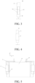
FIG. 3 is a schematic structural diagram of a cell lead-out sheet with a heat-conducting member being hidden according to an embodiment of the present application; -
FIG. 4 is a schematic structural diagram of a cell lead-out sheet according to an embodiment of the present application; -
FIG. 5 is a schematic structural diagram showing installation of a cell lead-out sheet and an electrode core according to another embodiment of the present application; -
FIG. 6 is a left view showing installation of a cell lead-out sheet according to an embodiment of the present application; -
FIG. 7 is a block diagram of a battery according to an embodiment of the present application; and -
FIG. 8 is a block diagram of an electric vehicle according to an embodiment of the present application. - The following clearly describes the specific implementations of the present application with reference to the accompanying drawings.
- The present application provides a cell lead-
out sheet 10. The cell lead-out sheet 10 may be widely used in battery assembly. For a more detailed description of the features of the cell lead-out sheet 10 in the solution, refer toFIG. 1 to FIG. 5 . -
FIG. 1 and FIG. 2 are schematic structural diagrams showing installation of a cell lead-out sheet 10 and anelectrode core 20.FIG. 1 is a schematic structural diagram of the cell lead-out sheet 10 with a heat-conductingmember 13 being hidden. The cell lead-out sheet 10 includes amain body 11 and two extendingbranches 12 extending from themain body 11. Themain body 11 is externally connected to a positive/negative terminal 40. The two extendingbranches 12 are respectively electrically connected to theelectrode core 20. As shown inFIG. 3 , the two extendingbranches 12 are spaced apart to form aninstallation gap 14. Theinstallation gap 14 is a space prefabricated for the subsequent welding of the cell lead-out sheet 10 andtabs 21 to facilitate placement of welding equipment. The heat-conductingelement 13 is arranged on a side of theinstallation gap 14 facing away from theelectrode core 20. Theelectrode core 20 in the embodiments is generally formed by winding a positive electrode plate, a separator and a negative electrode plate.Tabs 21 respectively extending from the positive and negative electrode plates for conducting current are arranged on two sides of thewound electrode core 20. To increase output power of theelectrode core 20 to reduce the internal resistance, generally a plurality oftabs 21 are press-fit to form an all-tab design, and the press-fit tabs 21 are electrically connected to the positive/negative terminal 40 outside through the cell lead-outsheets 10. The electrical connection between the cell lead-out sheet 10 and thetab 21 is achieved by welding the two extendingbranches 12 to two sides of thetab 21. As shown inFIG. 3 , to meet the requirements of battery arrangement, the two extendingbranches 12 need to be spaced apart, so as to form theinstallation gap 14. As shown inFIG. 2 , for the design of this embodiment, the heat-conductingelement 13 is arranged on the side of theinstallation gap 14 facing away from theelectrode core 21, and the heat-conductingmember 13 at least partially covers theinstallation gap 14. Therefore, the heat dissipation area of the cell lead-out sheet 10 is increased through the heat-conductingmember 13, thereby improving the heat dissipation effect of the cell lead-out sheet 10. It should be noted that the heat-conductingmember 13 may be a heat dissipation sheet, a heat dissipation net, or other structures capable of dissipating heat, which is not particularly limited herein. The arrangement of theheat dissipation sheet 13 in the installation gap is a reasonable utilization of the structure of the space, and increases the heat dissipation area of the cell lead-out sheet 10 and improves the heat dissipation effect without affecting the operation of theelectrode core 20. - Specifically, as shown in
FIG. 1 andFIG. 3 , an extending direction of themain body 11 is defined as a first direction X, an extending direction of the two extendingbranches 12 is defined as a second direction Y, and the two extendingbranches 12 are spaced apart from each other in a third direction Z. The first direction X, the second direction Y and the third direction Z are perpendicular to each other. - In a specific embodiment, as shown in
FIG. 2 ,FIG. 3, and FIG. 4 , the heat-conductingmember 13 completely covers theinstallation gap 14. In this embodiment, because the heat-conductingmember 13 completely covers theinstallation gap 14 between the extendingbranches 12, the heat dissipation area of the entire cell lead-out sheet 10 is increased, thereby maximizing the heat dissipation effect. The technical solution of the present application can properly utilize theinstallation gap 14 between the two extendingbranches 12 to increase the heat dissipation area of the cell lead-out sheet 10. Therefore, in this embodiment, the heat-conductingmember 13 completely covers theinstallation gap 14, so as to improve the heat dissipation effect as much as possible. - In a specific embodiment, as shown in
FIG. 2 ,FIG. 3, and FIG. 4 , a direction along which the two extendingbranches 12 are opposite to each other is defined as the third direction Z, and two ends of the heat-conductingmember 13 in the third direction Z are respectively connected to the two extendingbranches 12. Specifically, the two ends of the heat-conductingmember 13 in the third direction Z are respectively adhered to the two extendingbranches 12. Various adhesion methods may be used. For example, an adhesive is applied on the two ends of the heat-conductingmember 13, and then the two ends are adhered to the two extendingbranches 12 to completely cover theinstallation gap 14. Alternatively, the two ends of the heat-conductingmember 13 are placed on the extendingbranch 12 respectively, and then the heat-conductingmember 13 is fixed to the extendingbranch 12 with an adhesive tape to completely cover theinstallation gap 14. - In a specific embodiment, as shown in
FIG. 3, FIG. 4, and FIG. 5 , the direction along which the two extendingbranches 12 are opposite to each other is defined as the third direction Z, and one end of the heat-conductingmember 13 in the third direction Z is connected to one side of thetab 21. Specifically, to make the heat-conductingmember 13 more firmly installed, in this embodiment, one end of the heat-conductingmember 13 is connected to one side of thetab 21 by welding, and the other end of the heat-conductingmember 13 only needs to be bent to cover theinstallation gap 14. In another specific embodiment, the two ends of the heat-conductingmember 13 may be fixedly connected to the two sides of thetab 21 by an adhesive tape. It should be noted that the heat-conductingmember 13 may be connected to thetab 21 by any method as long as the heat-conductingmember 13 completely covers theinstallation gap 14. - In a specific embodiment, as shown in
FIG. 6 , a surface of one of the extendingbranches 12 fits to one side of thetab 21, and a surface of the other extendingbranch 12 fits to another side of thetab 21. Such a fitting design increases the power of current transmission on the one hand, and also increases the heat dissipation capability of the extendingbranches 12 on the other hand. - In a specific embodiment, as shown in
FIG. 3 andFIG. 6 , aconnection portion 16 is arranged on one end of the extendingbranches 12 away from themain body 11, and theconnection portions 16 are configured to connect the two extendingbranches 12. The design of theconnection portions 16 is to connect the two extendingbranches 12 to ensure the stability of the structure. - In a specific embodiment, as shown in
FIG. 6 , a surface of the extendingbranches 12 is connected to thetab 21 by welding. The welding method used herein may be ultrasonic welding or laser welding to ensure the flatness and stability of the structure. - It should be noted that the heat-conducting member in the present application is a material with good thermal conductivity.
- Specifically, the heat-conducting member is made of a metal material. The metal material may be one or more selected from aluminum, brass, copper, steel, or iron. It should be noted that after the heat-conducting member made of the metal material is selected, a side spacer may be added to the tab. Generally, the side spacer is sleeved on the side tab end. The side spacer is an insulating material, for example, plastic such as PP or PE, to prevent the heat-conducting member made of the metal material from contacting the housing of the battery, thereby avoiding problems such as current leakage and short circuit.
- Specifically, the heat-conducting member is made of thermally conductive silicone. The heat-conducting silicone material is an insulating thermally conductive material, such as one or more of aluminum oxide, silicon oxide, magnesium oxide, zinc oxide, aluminum nitride, boron nitride, magnesium oxide, silicon carbide, etc. The heat-conducting member made of the thermally conductive silicone have good insulation properties to avoid accidents such as short circuit or current leakage due to the arrangement of the heat-conducting member.
- Specifically, the heat-conducting member is made of composite ceramic. The composite ceramic herein is mainly a mixture of plastic and a highly thermally conductive material. The plastic may be one or more of polypropylene (PP) or polyethylene (PE). The highly thermally conductive material may be one or more of aluminum oxide, silicon oxide, magnesium oxide, zinc oxide, aluminum nitride, boron nitride, magnesium oxide, silicon carbide, etc. The heat-conducting member made of the composite ceramic not only meets the heat dissipation requirements, but also avoids the risk of short circuit or current leakage.
- In a specific embodiment, the heat-conducting member is a carbon-based material. The carbon-based material herein includes a heat dissipation layer and a thermally conductive insulation layer. The heat dissipation layer may be one or more of graphene, carbon black, carbon tubes, graphite, or other carbon-based materials. The thermally conductive insulation layer may be one or more of thermally conductive silica gel or composite ceramic.
- According to another aspect, referring to
FIG. 7 , the present application provides abattery 100, which includes a housing 30, anelectrode core 20 and a cell lead-out sheet 10. The cell lead-out sheet 10 and theelectrode core 20 are electrically connected to each other and are received in the housing 30. In an embodiment, the cell lead-out sheet is electrically connected to a tab of the electrode core, and the cell lead-out sheet and the electrode core are both received in the housing. Specifically, the housing includes a lower housing and a cover plate. The lower housing includes a receiving space. The cell lead-out sheet is arranged in the receiving space. A positive terminal and/or a negative terminal are arranged on the cover plate. The tab is connected to the positive terminal and/or the negative terminal through the cell lead-out sheet. In this embodiment, the battery has a good heat dissipation effect due to the design of the heat-conducting member on the cell lead-out chip, thereby avoiding the danger caused by an excessively high temperature of the electrode core during operation. - The battery provided in this embodiment can greatly reduce the contact thermal resistance on the side of the electrode core after using the cell lead-out sheet including the heat-conducting member. A set of actual measurement data is used for comparison and description.
- Experimental steps are as follows. (1) The cell lead-out sheet including the heat-conducting member was used to assemble a battery. (2) At least three thermocouples were arranged on each outer surface of the housing to ensure the accuracy of temperature sampling. Test conditions were: 25°C, 50% SOC battery, continuous charging and discharging at 6C/10S. When the temperature of each thermocouple reached equilibrium (equilibrium condition: temperature change of 0.5°C/10 min), experimental data was obtained under the above conditions. (3) An initial cell was taken, from which the heat-conducting member was removed. Then, the cell was tested according to the above method, and experimental data was obtained again. (4) The contact thermal resistance in each directions of the cell was calculated through simulation according to the actually measured data.
- Data in Table 1 below was obtained:
Table 1 Unit (K∗m2/W) Not including the heat-conducting member Including the heat-conducting member Side 0.002915 0.0015 Large surface 0.00245 0.00245 Top surface 0.04 0.04 Bottom surface 0.02 0.02 - It can be seen from Table 1 that the contact thermal resistance data of the side of the electrode core decreased from 0.002915 K∗m2/W to 0.0015 K∗m2/W after the heat-conducting member was added, indicating that the cell lead-out sheet including the heat-conducting member in the present application had a good effect on the heat dissipation of the electrode core.
- According to a third aspect, referring to
FIG. 8 , the present application provides anelectric vehicle 1000, including the above-mentionedbattery 100. In the foregoing embodiments, the cell lead-out sheet of the battery has a good heat dissipation effect, which improves the heat dissipation performance of the electrode core and avoids the safety risks caused by an excessively high temperature of the electrode core. In addition, if the heat dissipation performance of the electrode core itself is poor, external equipment is required for liquid cooling, which increases the energy consumption of the electric vehicle and brings about the problem of high carbon emissions. Therefore, the present application can also reduce the thermal resistance of the entire battery pack and reduce the energy consumption of the entire vehicle. - The foregoing contents are merely specific implementations of the present application, but are not intended to limit the protection scope of the present application. Any variation or replacement readily figured out by a person skilled in the art within the technical scope disclosed in the present application shall fall within the protection scope of the present application. Therefore, the protection scope of the present application shall be subject to the protection scope of the claims.
Claims (20)
- A cell lead-out sheet, comprising a heat-conducting member, a main body, and two extending branches bent and extending from one end of the main body, wherein the main body is configured to electrically connect a positive terminal and/or a negative terminal of a battery, the two extending branches are respectively configured to electrically connect to tabs of an electrode core in the battery, the two extending branches are spaced apart from each other to form an installation gap, the heat-conducting member is arranged on a side of the two extending branches facing away from the electrode core, and the heat-conducting member at least partially covers the installation gap.
- The cell lead-out sheet according to claim 1, wherein the heat-conducting member completely covers the installation gap.
- The cell lead-out sheet according to claim 2, wherein two ends of the heat-conducting member are respectively connected to the two extending branches.
- The cell lead-out sheet according to claim 2, wherein one end of the heat-conducting member is configured to connect to one side of the tab, and another end of the heat-conducting member is configured to bend to cover the installation gap.
- The cell lead-out sheet according to claim 3 or 4, wherein an extending direction of the main body is defined as a first direction, an extending direction of the two extending branches is defined as a second direction, the two extending branches are spaced apart from each other in a third direction, and the first direction, the second direction, and the third direction are perpendicular to each other.
- The cell lead-out sheet according to claim 5, wherein a surface of one of the extending branches fits to one side of the tab, and a surface of the other extending branch fits to another side of the tab.
- The cell lead-out sheet according to claim 6, further comprising a connection portion located on one end of the extending branches away from the main body, wherein the connection portions are configured to connect the two extending branches.
- The cell lead-out sheet according to claim 6 or 7, wherein the extending branches are connected to the tab by welding.
- The cell lead-out sheet according to claim 8, wherein the extending branches are connected to the tab by ultrasonic welding or laser welding.
- The cell lead-out sheet according to any one of claims 1 to 9, wherein the heat-conducting member is made of a metal material.
- The cell lead-out sheet according to claim 10, wherein a side spacer made of an insulating material is arranged on the tab to space the heat-conducting member apart from a housing of the battery.
- The cell lead-out sheet according to any one of claims 1 to 9, wherein the heat-conducting member is made of thermally conductive silicone.
- The cell lead-out sheet according to any one of claims 1 to 9, wherein the heat-conducting member is made of composite ceramic.
- The cell lead-out sheet according to claim 13, wherein the composite ceramic comprises a mixture of plastic and a highly thermally conductive material.
- The cell lead-out sheet according to any one of claims 1 to 9, wherein the heat-conducting member is a carbon-based material.
- The cell lead-out sheet according to claim 15, wherein the carbon-based material comprises a heat dissipation layer and a thermally conductive insulation layer.
- A battery, comprising a housing, an electrode core, and the cell lead-out sheet according to any one of claims 1 to 16, wherein the electrode core and the cell lead-out sheet are received in the housing
- The battery according to claim 17, wherein the housing comprises a lower housing and a cover plate, the lower housing comprises a receiving space, and the cell lead-out sheet is arranged in the receiving space.
- The battery according to claim 18, wherein a positive terminal and/or a negative terminal are arranged on the cover plate, and the tabs are connected to the positive terminal and/or the negative terminal through the cell lead-out sheets.
- An electric vehicle, comprising the battery according to any one of claims 17 to 19.
Applications Claiming Priority (2)
| Application Number | Priority Date | Filing Date | Title |
|---|---|---|---|
| CN202021216701.6U CN212277344U (en) | 2020-06-28 | 2020-06-28 | Battery cell lead-out sheet, battery and electric automobile |
| PCT/CN2021/100333 WO2022001660A1 (en) | 2020-06-28 | 2021-06-16 | Cell lead-out piece, battery, and electric vehicle |
Publications (1)
| Publication Number | Publication Date |
|---|---|
| EP4175048A1 true EP4175048A1 (en) | 2023-05-03 |
Family
ID=73883138
Family Applications (1)
| Application Number | Title | Priority Date | Filing Date |
|---|---|---|---|
| EP21831959.8A Pending EP4175048A1 (en) | 2020-06-28 | 2021-06-16 | Cell lead-out piece, battery, and electric vehicle |
Country Status (6)
| Country | Link |
|---|---|
| US (1) | US20230119288A1 (en) |
| EP (1) | EP4175048A1 (en) |
| JP (1) | JP2023532716A (en) |
| KR (1) | KR20230028527A (en) |
| CN (1) | CN212277344U (en) |
| WO (1) | WO2022001660A1 (en) |
Families Citing this family (3)
| Publication number | Priority date | Publication date | Assignee | Title |
|---|---|---|---|---|
| CN212277344U (en) * | 2020-06-28 | 2021-01-01 | 比亚迪股份有限公司 | Battery cell lead-out sheet, battery and electric automobile |
| CN113964417A (en) * | 2021-10-20 | 2022-01-21 | 东莞新能安科技有限公司 | Battery pack and electric equipment |
| CN115189077B (en) * | 2022-09-06 | 2023-01-17 | 楚能新能源股份有限公司 | Square battery cell, assembling method of square battery cell and battery module |
Family Cites Families (7)
| Publication number | Priority date | Publication date | Assignee | Title |
|---|---|---|---|---|
| CN201663187U (en) * | 2010-03-26 | 2010-12-01 | 中大工业集团公司 | Current conducting body for high-capacity high-power battery capacitor |
| CN202549971U (en) * | 2012-04-06 | 2012-11-21 | 盐城中威客车有限公司 | Drainage body device of high-capacity capacitor and lithium ion battery |
| CN106972119B (en) * | 2016-01-13 | 2020-10-23 | 比亚迪股份有限公司 | Cover plate assembly, battery containing cover plate assembly and battery pack |
| CN206650127U (en) * | 2017-02-28 | 2017-11-17 | 比亚迪股份有限公司 | A kind of cell, double cell group and battery modules |
| CN108807827A (en) * | 2017-04-28 | 2018-11-13 | 比亚迪股份有限公司 | A kind of electrode leading-out sheet and battery |
| CN209675429U (en) * | 2019-05-21 | 2019-11-22 | 宁德时代新能源科技股份有限公司 | A kind of secondary cell |
| CN212277344U (en) * | 2020-06-28 | 2021-01-01 | 比亚迪股份有限公司 | Battery cell lead-out sheet, battery and electric automobile |
-
2020
- 2020-06-28 CN CN202021216701.6U patent/CN212277344U/en active Active
-
2021
- 2021-06-16 WO PCT/CN2021/100333 patent/WO2022001660A1/en unknown
- 2021-06-16 KR KR1020237003056A patent/KR20230028527A/en unknown
- 2021-06-16 JP JP2022581394A patent/JP2023532716A/en active Pending
- 2021-06-16 EP EP21831959.8A patent/EP4175048A1/en active Pending
-
2022
- 2022-12-19 US US18/083,931 patent/US20230119288A1/en active Pending
Also Published As
| Publication number | Publication date |
|---|---|
| US20230119288A1 (en) | 2023-04-20 |
| CN212277344U (en) | 2021-01-01 |
| KR20230028527A (en) | 2023-02-28 |
| WO2022001660A1 (en) | 2022-01-06 |
| JP2023532716A (en) | 2023-07-31 |
Similar Documents
| Publication | Publication Date | Title |
|---|---|---|
| EP4175048A1 (en) | Cell lead-out piece, battery, and electric vehicle | |
| KR101526667B1 (en) | Device for cooling and heating battery module of vehicle | |
| EP2425485B1 (en) | A high voltage modular battery with electrically-insulated cell module and interconnector peripheries | |
| KR101571774B1 (en) | Battery Cell of Improved Cooling Efficiency | |
| KR101874181B1 (en) | Battery assembly | |
| CN107275559B (en) | Battery pack device | |
| CN111916647A (en) | Soft packet of power battery module | |
| CN210403868U (en) | Battery module and battery | |
| KR20200065192A (en) | Battery Pack Having Heat Dissipating Member | |
| JP5599106B2 (en) | Secondary battery and secondary battery module | |
| KR20180081235A (en) | Battery Cell of Improved Cooling Efficiency | |
| CN110635083A (en) | Rapid heating battery module | |
| CN211957702U (en) | Heat release explosion-proof lithium ion battery | |
| CN213459887U (en) | Battery heating film and lithium ion power battery | |
| CN210866417U (en) | Battery module fast dispels heat | |
| CN209948006U (en) | Laminate polymer battery module and electric vehicle who has this laminate polymer battery module | |
| JP2009016235A (en) | Power storage device | |
| CN111082187A (en) | Battery package cooling device | |
| CN110690529A (en) | Battery module fast dispels heat | |
| CN219717007U (en) | Battery pack and vehicle | |
| CN219959301U (en) | Energy storage battery pack | |
| CN218957853U (en) | High-capacity battery | |
| CN212934804U (en) | Soft packet of power battery module | |
| CN218568988U (en) | Battery module and electric device | |
| EP3934009B1 (en) | Battery module and battery pack including same |
Legal Events
| Date | Code | Title | Description |
|---|---|---|---|
| STAA | Information on the status of an ep patent application or granted ep patent |
Free format text: STATUS: THE INTERNATIONAL PUBLICATION HAS BEEN MADE |
|
| PUAI | Public reference made under article 153(3) epc to a published international application that has entered the european phase |
Free format text: ORIGINAL CODE: 0009012 |
|
| STAA | Information on the status of an ep patent application or granted ep patent |
Free format text: STATUS: REQUEST FOR EXAMINATION WAS MADE |
|
| 17P | Request for examination filed |
Effective date: 20230109 |
|
| AK | Designated contracting states |
Kind code of ref document: A1 Designated state(s): AL AT BE BG CH CY CZ DE DK EE ES FI FR GB GR HR HU IE IS IT LI LT LU LV MC MK MT NL NO PL PT RO RS SE SI SK SM TR |
|
| DAV | Request for validation of the european patent (deleted) | ||
| DAX | Request for extension of the european patent (deleted) |