EP4175034A1 - Button-type secondary battery - Google Patents
Button-type secondary battery Download PDFInfo
- Publication number
- EP4175034A1 EP4175034A1 EP21869745.6A EP21869745A EP4175034A1 EP 4175034 A1 EP4175034 A1 EP 4175034A1 EP 21869745 A EP21869745 A EP 21869745A EP 4175034 A1 EP4175034 A1 EP 4175034A1
- Authority
- EP
- European Patent Office
- Prior art keywords
- button
- secondary battery
- type secondary
- electrode
- bent
- Prior art date
- Legal status (The legal status is an assumption and is not a legal conclusion. Google has not performed a legal analysis and makes no representation as to the accuracy of the status listed.)
- Pending
Links
- 239000012212 insulator Substances 0.000 claims description 59
- 229920001707 polybutylene terephthalate Polymers 0.000 claims description 7
- 239000000463 material Substances 0.000 claims description 6
- -1 polybutylene terephthalate Polymers 0.000 claims description 6
- STZCRXQWRGQSJD-GEEYTBSJSA-M methyl orange Chemical compound [Na+].C1=CC(N(C)C)=CC=C1\N=N\C1=CC=C(S([O-])(=O)=O)C=C1 STZCRXQWRGQSJD-GEEYTBSJSA-M 0.000 claims description 5
- 229940012189 methyl orange Drugs 0.000 claims description 5
- 239000003792 electrolyte Substances 0.000 abstract description 15
- SECXISVLQFMRJM-UHFFFAOYSA-N N-Methylpyrrolidone Chemical compound CN1CCCC1=O SECXISVLQFMRJM-UHFFFAOYSA-N 0.000 description 4
- YEJRWHAVMIAJKC-UHFFFAOYSA-N 4-Butyrolactone Chemical compound O=C1CCCO1 YEJRWHAVMIAJKC-UHFFFAOYSA-N 0.000 description 3
- WEVYAHXRMPXWCK-UHFFFAOYSA-N Acetonitrile Chemical compound CC#N WEVYAHXRMPXWCK-UHFFFAOYSA-N 0.000 description 3
- 238000005516 engineering process Methods 0.000 description 3
- 229910001416 lithium ion Inorganic materials 0.000 description 3
- DHKHKXVYLBGOIT-UHFFFAOYSA-N 1,1-Diethoxyethane Chemical compound CCOC(C)OCC DHKHKXVYLBGOIT-UHFFFAOYSA-N 0.000 description 2
- OIFBSDVPJOWBCH-UHFFFAOYSA-N Diethyl carbonate Chemical compound CCOC(=O)OCC OIFBSDVPJOWBCH-UHFFFAOYSA-N 0.000 description 2
- IAZDPXIOMUYVGZ-UHFFFAOYSA-N Dimethylsulphoxide Chemical compound CS(C)=O IAZDPXIOMUYVGZ-UHFFFAOYSA-N 0.000 description 2
- KMTRUDSVKNLOMY-UHFFFAOYSA-N Ethylene carbonate Chemical compound O=C1OCCO1 KMTRUDSVKNLOMY-UHFFFAOYSA-N 0.000 description 2
- HBBGRARXTFLTSG-UHFFFAOYSA-N Lithium ion Chemical compound [Li+] HBBGRARXTFLTSG-UHFFFAOYSA-N 0.000 description 2
- WYURNTSHIVDZCO-UHFFFAOYSA-N Tetrahydrofuran Chemical compound C1CCOC1 WYURNTSHIVDZCO-UHFFFAOYSA-N 0.000 description 2
- 230000008901 benefit Effects 0.000 description 2
- 238000006243 chemical reaction Methods 0.000 description 2
- 230000008878 coupling Effects 0.000 description 2
- 238000010168 coupling process Methods 0.000 description 2
- 238000005859 coupling reaction Methods 0.000 description 2
- VUPKGFBOKBGHFZ-UHFFFAOYSA-N dipropyl carbonate Chemical compound CCCOC(=O)OCCC VUPKGFBOKBGHFZ-UHFFFAOYSA-N 0.000 description 2
- JBTWLSYIZRCDFO-UHFFFAOYSA-N ethyl methyl carbonate Chemical compound CCOC(=O)OC JBTWLSYIZRCDFO-UHFFFAOYSA-N 0.000 description 2
- 238000000034 method Methods 0.000 description 2
- RUOJZAUFBMNUDX-UHFFFAOYSA-N propylene carbonate Chemical compound CC1COC(=O)O1 RUOJZAUFBMNUDX-UHFFFAOYSA-N 0.000 description 2
- 238000007086 side reaction Methods 0.000 description 2
- XTHFKEDIFFGKHM-UHFFFAOYSA-N Dimethoxyethane Chemical compound COCCOC XTHFKEDIFFGKHM-UHFFFAOYSA-N 0.000 description 1
- WHXSMMKQMYFTQS-UHFFFAOYSA-N Lithium Chemical compound [Li] WHXSMMKQMYFTQS-UHFFFAOYSA-N 0.000 description 1
- 229910052783 alkali metal Inorganic materials 0.000 description 1
- 229910052782 aluminium Inorganic materials 0.000 description 1
- XAGFODPZIPBFFR-UHFFFAOYSA-N aluminium Chemical compound [Al] XAGFODPZIPBFFR-UHFFFAOYSA-N 0.000 description 1
- 150000001450 anions Chemical class 0.000 description 1
- 230000008859 change Effects 0.000 description 1
- IEJIGPNLZYLLBP-UHFFFAOYSA-N dimethyl carbonate Chemical compound COC(=O)OC IEJIGPNLZYLLBP-UHFFFAOYSA-N 0.000 description 1
- 230000000694 effects Effects 0.000 description 1
- 238000003912 environmental pollution Methods 0.000 description 1
- 239000002803 fossil fuel Substances 0.000 description 1
- 235000015110 jellies Nutrition 0.000 description 1
- 239000008274 jelly Substances 0.000 description 1
- 229910052744 lithium Inorganic materials 0.000 description 1
- 229910052751 metal Inorganic materials 0.000 description 1
- 239000002184 metal Substances 0.000 description 1
- CEQFOVLGLXCDCX-WUKNDPDISA-N methyl red Chemical compound C1=CC(N(C)C)=CC=C1\N=N\C1=CC=CC=C1C(O)=O CEQFOVLGLXCDCX-WUKNDPDISA-N 0.000 description 1
- 239000000203 mixture Substances 0.000 description 1
- 238000012986 modification Methods 0.000 description 1
- 230000004048 modification Effects 0.000 description 1
- 239000003960 organic solvent Substances 0.000 description 1
- 229920000642 polymer Polymers 0.000 description 1
- 238000010248 power generation Methods 0.000 description 1
- 230000009257 reactivity Effects 0.000 description 1
- 150000003839 salts Chemical class 0.000 description 1
- 238000000926 separation method Methods 0.000 description 1
- YLQBMQCUIZJEEH-UHFFFAOYSA-N tetrahydrofuran Natural products C=1C=COC=1 YLQBMQCUIZJEEH-UHFFFAOYSA-N 0.000 description 1
- 125000001814 trioxo-lambda(7)-chloranyloxy group Chemical group *OCl(=O)(=O)=O 0.000 description 1
- 238000004804 winding Methods 0.000 description 1
Images


Classifications
-
- H—ELECTRICITY
- H01—ELECTRIC ELEMENTS
- H01M—PROCESSES OR MEANS, e.g. BATTERIES, FOR THE DIRECT CONVERSION OF CHEMICAL ENERGY INTO ELECTRICAL ENERGY
- H01M10/00—Secondary cells; Manufacture thereof
- H01M10/04—Construction or manufacture in general
- H01M10/0422—Cells or battery with cylindrical casing
- H01M10/0427—Button cells
-
- H—ELECTRICITY
- H01—ELECTRIC ELEMENTS
- H01M—PROCESSES OR MEANS, e.g. BATTERIES, FOR THE DIRECT CONVERSION OF CHEMICAL ENERGY INTO ELECTRICAL ENERGY
- H01M50/00—Constructional details or processes of manufacture of the non-active parts of electrochemical cells other than fuel cells, e.g. hybrid cells
- H01M50/10—Primary casings; Jackets or wrappings
- H01M50/102—Primary casings; Jackets or wrappings characterised by their shape or physical structure
- H01M50/109—Primary casings; Jackets or wrappings characterised by their shape or physical structure of button or coin shape
-
- H—ELECTRICITY
- H01—ELECTRIC ELEMENTS
- H01M—PROCESSES OR MEANS, e.g. BATTERIES, FOR THE DIRECT CONVERSION OF CHEMICAL ENERGY INTO ELECTRICAL ENERGY
- H01M10/00—Secondary cells; Manufacture thereof
- H01M10/42—Methods or arrangements for servicing or maintenance of secondary cells or secondary half-cells
- H01M10/4228—Leak testing of cells or batteries
-
- H—ELECTRICITY
- H01—ELECTRIC ELEMENTS
- H01M—PROCESSES OR MEANS, e.g. BATTERIES, FOR THE DIRECT CONVERSION OF CHEMICAL ENERGY INTO ELECTRICAL ENERGY
- H01M10/00—Secondary cells; Manufacture thereof
- H01M10/42—Methods or arrangements for servicing or maintenance of secondary cells or secondary half-cells
- H01M10/48—Accumulators combined with arrangements for measuring, testing or indicating the condition of cells, e.g. the level or density of the electrolyte
- H01M10/488—Cells or batteries combined with indicating means for external visualization of the condition, e.g. by change of colour or of light density
-
- H—ELECTRICITY
- H01—ELECTRIC ELEMENTS
- H01M—PROCESSES OR MEANS, e.g. BATTERIES, FOR THE DIRECT CONVERSION OF CHEMICAL ENERGY INTO ELECTRICAL ENERGY
- H01M50/00—Constructional details or processes of manufacture of the non-active parts of electrochemical cells other than fuel cells, e.g. hybrid cells
- H01M50/10—Primary casings; Jackets or wrappings
- H01M50/147—Lids or covers
- H01M50/148—Lids or covers characterised by their shape
- H01M50/153—Lids or covers characterised by their shape for button or coin cells
-
- H—ELECTRICITY
- H01—ELECTRIC ELEMENTS
- H01M—PROCESSES OR MEANS, e.g. BATTERIES, FOR THE DIRECT CONVERSION OF CHEMICAL ENERGY INTO ELECTRICAL ENERGY
- H01M50/00—Constructional details or processes of manufacture of the non-active parts of electrochemical cells other than fuel cells, e.g. hybrid cells
- H01M50/10—Primary casings; Jackets or wrappings
- H01M50/147—Lids or covers
- H01M50/166—Lids or covers characterised by the methods of assembling casings with lids
- H01M50/167—Lids or covers characterised by the methods of assembling casings with lids by crimping
-
- H—ELECTRICITY
- H01—ELECTRIC ELEMENTS
- H01M—PROCESSES OR MEANS, e.g. BATTERIES, FOR THE DIRECT CONVERSION OF CHEMICAL ENERGY INTO ELECTRICAL ENERGY
- H01M50/00—Constructional details or processes of manufacture of the non-active parts of electrochemical cells other than fuel cells, e.g. hybrid cells
- H01M50/10—Primary casings; Jackets or wrappings
- H01M50/183—Sealing members
- H01M50/184—Sealing members characterised by their shape or structure
-
- H—ELECTRICITY
- H01—ELECTRIC ELEMENTS
- H01M—PROCESSES OR MEANS, e.g. BATTERIES, FOR THE DIRECT CONVERSION OF CHEMICAL ENERGY INTO ELECTRICAL ENERGY
- H01M50/00—Constructional details or processes of manufacture of the non-active parts of electrochemical cells other than fuel cells, e.g. hybrid cells
- H01M50/10—Primary casings; Jackets or wrappings
- H01M50/183—Sealing members
- H01M50/19—Sealing members characterised by the material
- H01M50/193—Organic material
-
- H—ELECTRICITY
- H01—ELECTRIC ELEMENTS
- H01M—PROCESSES OR MEANS, e.g. BATTERIES, FOR THE DIRECT CONVERSION OF CHEMICAL ENERGY INTO ELECTRICAL ENERGY
- H01M50/00—Constructional details or processes of manufacture of the non-active parts of electrochemical cells other than fuel cells, e.g. hybrid cells
- H01M50/30—Arrangements for facilitating escape of gases
-
- H—ELECTRICITY
- H01—ELECTRIC ELEMENTS
- H01M—PROCESSES OR MEANS, e.g. BATTERIES, FOR THE DIRECT CONVERSION OF CHEMICAL ENERGY INTO ELECTRICAL ENERGY
- H01M50/00—Constructional details or processes of manufacture of the non-active parts of electrochemical cells other than fuel cells, e.g. hybrid cells
- H01M50/50—Current conducting connections for cells or batteries
- H01M50/528—Fixed electrical connections, i.e. not intended for disconnection
-
- H—ELECTRICITY
- H01—ELECTRIC ELEMENTS
- H01M—PROCESSES OR MEANS, e.g. BATTERIES, FOR THE DIRECT CONVERSION OF CHEMICAL ENERGY INTO ELECTRICAL ENERGY
- H01M50/00—Constructional details or processes of manufacture of the non-active parts of electrochemical cells other than fuel cells, e.g. hybrid cells
- H01M50/50—Current conducting connections for cells or batteries
- H01M50/531—Electrode connections inside a battery casing
- H01M50/533—Electrode connections inside a battery casing characterised by the shape of the leads or tabs
-
- Y—GENERAL TAGGING OF NEW TECHNOLOGICAL DEVELOPMENTS; GENERAL TAGGING OF CROSS-SECTIONAL TECHNOLOGIES SPANNING OVER SEVERAL SECTIONS OF THE IPC; TECHNICAL SUBJECTS COVERED BY FORMER USPC CROSS-REFERENCE ART COLLECTIONS [XRACs] AND DIGESTS
- Y02—TECHNOLOGIES OR APPLICATIONS FOR MITIGATION OR ADAPTATION AGAINST CLIMATE CHANGE
- Y02E—REDUCTION OF GREENHOUSE GAS [GHG] EMISSIONS, RELATED TO ENERGY GENERATION, TRANSMISSION OR DISTRIBUTION
- Y02E60/00—Enabling technologies; Technologies with a potential or indirect contribution to GHG emissions mitigation
- Y02E60/10—Energy storage using batteries
-
- Y—GENERAL TAGGING OF NEW TECHNOLOGICAL DEVELOPMENTS; GENERAL TAGGING OF CROSS-SECTIONAL TECHNOLOGIES SPANNING OVER SEVERAL SECTIONS OF THE IPC; TECHNICAL SUBJECTS COVERED BY FORMER USPC CROSS-REFERENCE ART COLLECTIONS [XRACs] AND DIGESTS
- Y02—TECHNOLOGIES OR APPLICATIONS FOR MITIGATION OR ADAPTATION AGAINST CLIMATE CHANGE
- Y02P—CLIMATE CHANGE MITIGATION TECHNOLOGIES IN THE PRODUCTION OR PROCESSING OF GOODS
- Y02P70/00—Climate change mitigation technologies in the production process for final industrial or consumer products
- Y02P70/50—Manufacturing or production processes characterised by the final manufactured product
Definitions
- the present invention relates to a button-type secondary battery, and more particularly, to a button-type secondary battery, which is capable of collecting a gas within the battery even if an excessive internal pressure is generated by the gas generated in the battery to prevent the battery from being disassembled or prevent a gas that is harmful to the human body from leaking to the outside of the battery by the gas pressure and prevent an electrolyte from leaking to the outside of the battery.
- lithium secondary batteries such as lithium ion batteries and lithium ion polymer batteries having advantages such as high energy density, discharge voltage, and output stability.
- the secondary batteries are classified into cylindrical batteries and prismatic batteries, in which an electrode assembly is embedded in a cylindrical or prismatic metal can, and pouch-type batteries, in which an electrode assembly is embedded in a pouch-type case made of an aluminum laminate sheet according to shapes of battery cases. Also, recently, due to the trend of smaller wearable devices, the importance of developing small batteries such as button-type secondary batteries has been highlighted.
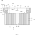
- FIG. 1 is a cross-sectional view of a button-type secondary battery according to the related art.
- a button-shaped secondary battery 10 has a shape that is divided into upper and lower housings and has a structure in which an upper cylindrical can 4 and a lower cylindrical can 3 are press-fitted. That is, an outer diameter of the lower cylindrical can 3 is slightly larger than that of an upper portion thereof to realize the press-fitting.
- the press-fitting it is the principle that a shape of the button-type secondary battery is maintained due to friction force due to the press-fitting.
- the upper can 4 and the lower can 3 are manufactured to match a size of an internal electrode assembly 1 so as to be press-fitted with each other, and thus, there is no available space therein.
- the button-type secondary battery 10 according to the related art had a structure with a high possibility of leakage of the electrolyte. That is, since a leak path through which the electrolyte leaks is simple, possibility of leakage of the electrolyte is high, and thus, many studies have been conducted to solve this problem.
- the present invention has been devised to solve the above problems, and an object of the present invention is to collect a gas within the battery even if an excessive internal pressure is generated by the gas generated in the battery so as to prevent the battery from being disassembled or prevent a gas that is harmful to the human body from leaking to the outside of the battery by the gas pressure and prevent an electrolyte from leaking to the outside of the battery.
- a collection space in which an internal gas is collected may be provided between the upper can and the electrode assembly.
- the upper can may comprise: an upper can electrode terminal part connected to an electrode of the electrode assembly to form a terminal and configured to cover the opening of the upper end of the lower can; a first bent part bent to extend from an end of the upper can electrode terminal part toward a bottom surface of the lower can; and a second bent part bent to extend from an end of the first bent part in a direction of a central axis of the lower can and disposed inside the beading part.
- the lower can may comprise a lower can upper end vertical part bent to extend from an end of the beading part toward the upper can electrode terminal part.
- the lower can upper end vertical part and the first bent part may extend in a direction parallel to each other and be disposed to face each other.
- the button-type secondary battery may further comprise an insulator configured to prevent the upper can and the lower can from being in contact with each other.
- the insulator may be made of a polybutylene terephthalate (PBT) material.
- PBT polybutylene terephthalate
- the insulator may comprise: a first insulator portion filled in a space surrounded by a top surface of the beading part, the lower can upper end vertical part, and the upper can electrode terminal part; a second insulator portion extending from the first insulator portion and filled in a space formed between the first bent part and the lower can upper end vertical part; and a third insulator portion extending from the second insulator portion and filled in a space formed between the second bent part and the beading part.
- a center hole may be formed in a center of the electrode assembly, and a center pin may be provided in the center hole so as to be fully filled in the center hole.
- the button-type secondary battery may further comprise an electrode tab configured to connect an electrode of the electrode assembly to the upper can electrode terminal part,
- the electrode tab may have one end connected to the electrode of the electrode assembly, and
- the electrode tab may have the other end connected to a bottom surface of the upper can electrode terminal part in a C-shape.
- the upper can may further comprise an upper can protrusion protruding from at least one of the upper can electrode terminal part, the first bent part, or the second bent part toward the insulator.
- the lower can may further comprise a lower can protrusion protruding from at least one of the beading part or the lower can upper end vertical part toward the insulator.
- a methyl orange PH sheet may be attached to an outer wall of the lower can.
- the button-type secondary battery according to the present invention relates to the button-shaped secondary battery, of which a diameter is greater than a length, and may comprise the lower can, into which the electrode assembly is inserted, and the upper can covering the opening of the upper end of the lower can, wherein the beading part that is recessed inward may be provided in the upper end of the lower can, the end of the upper can may have the bent shape so that the upper can and the lower can are coupled to each other while an end point of the end of the upper can is inserted into the beading part.
- the gas inside the battery may be collected to prevent the battery from being disassembled or prevent the gas that is harmful to the human body from leaking to the outside of the battery by the gas pressure and prevent the electrolyte from leaking to the outside of the battery.
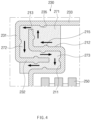
- FIG. 2 is a cross-sectional view of a button-type secondary battery according to Embodiment 1 of the present invention.
- a button-type secondary battery 100 according to Embodiment 1 of the present invention may be a battery having a cylindrical shape, and a diameter of the cylindrical battery may be larger than a height of the battery.
- the button-type secondary battery 100 according to Embodiment 1 of the present invention may comprise an electrode assembly 150, a lower can 110, and an upper can 130.
- the electrode assembly 150 may have a shape in which electrodes 151 and separators 152 are alternately stacked to be wound.
- the electrode assembly 150 may be inserted into the lower can 110.
- the lower can 110 may have an opened upper end in a cylindrical shape.
- the electrode assembly 150 may be in the form of a jelly roll.
- a winding axis of the electrode assembly 150 may be disposed in a shape that is perpendicular to the ground.
- the upper can 130 may have a plate shape or a stepped plate shape.
- the upper can 130 may have a shape that covers the opening of the upper end of the lower can 110.
- An inwardly recessed beading part 111 may be provided in an upper portion of the lower can 110.
- the beading part 111 may be formed on an entire circumference along an outer circumferential surface of the lower can 110.
- the beading part 111 may have a cross-sectional shape that is recessed in a shape that is angled at an angle of 90 degrees or may have a shape that is recessed in the form of a curved surface, unlike the drawing.
- an end of the upper can 130 is bent, and the upper can 130 and the lower can 110 are coupled to each other while an end point 134 of the end of the upper can is inserted into the beading part 111.
- An insulator 170 for preventing the upper can 130 and the lower can 110 from being in contact with each other may be further provided.
- a portion between the end of the upper can 130 having the bent shape and an upper end of the lower can 110 may be a portion at which the upper can 130 and the lower can 110 are directly coupled to each other.
- the insulator 170 may be provided to be interposed into the portion.
- the end of the upper can 130 may be bent or be curved in a bent shape. In the bent shape, an end of the upper end may be in the form of being inserted with a pressure into the beading unit 111. The end of the upper end may hold the upper end of the lower can 110 comprising the beading portion 111 and the insulator 170 together in a press-fit manner. Since the upper can 130 and the lower can 110 are coupled to each other by applying a pressure, the upper can 130 and the lower can 110 may not be easily separated from each other, but be firmly coupled to each other.
- the battery may not be disassembled the pressure, and the gas that is harmful to the human body inside the battery may not leak to the outside of the battery.
- the insulator 170 may be made of a polybutylene terephthalate (PBT) material.
- PBT polybutylene terephthalate
- the PBT material may have good mechanical properties, and in particular, high rigidity to realize a battery having excellent airtightness and durability.
- the upper can 130 may comprise an upper can electrode terminal part 133, a first bent part 131, and a second bent part 132.
- the upper can electrode terminal part 133 means a portion connected to the electrode 151 of the electrode assembly 150 to form a terminal and may be a portion covering the opening of the upper end of the lower can 110.
- the upper can electrode terminal part 133 may be a terminal connecting an external device to the secondary battery according to the present invention.
- the upper can electrode terminal part 133 may be a positive electrode terminal.
- first bent part 131 of the upper can 130 may be a portion that is bent from the end of the upper can electrode terminal part 133 toward a bottom surface 114 of the lower can to extend.
- the second bent part 132 may be a portion that is bent to extend from an end of the first bent part 131 in a direction of a central axis of the lower can 110.
- the second bent part 132 may be disposed inside the beading part 111. Since the second bent part 132 is coupled to the inside of the beading part 111 in a state of being pressed in the beading part 111, the separation of the upper can 130 and the lower can 110 may not easily occur.
- the lower can 110 may comprises a lower can upper end vertical part 113 bent to extend from the end of the beading part 111 toward the upper can electrode terminal part 133.
- the lower can upper end vertical part 113 may be bent in a vertical direction from the upper end of the beading portion 111 to extend upward.
- the upward extension toward the upper can electrode terminal part 133 should be regarded as belonging to the scope of the present invention.
- the lower can upper end vertical part 113 and the first bent part 131 of the upper can 130 may extend in a direction parallel to each other, but may be disposed to face each other.
- a collection space 120 in which the internal gas is collected is provided between the upper can 130 and the electrode assembly 150. More specifically, the collection space 120 that is a space for collecting a gas may be provided between the terminal part of the electrode 151 of the upper can 130 and the electrode assembly 150.
- the gas may ascend to be filled in the collection space 120.
- the collection space 120 between the upper can 130 and the electrode assembly 150 is an available space for the gas collection to serve to prevent a gas from leaking out of the battery (since a hole is not formed in the upper can 130, the gas is not discharged to the outside by passing through the upper can 130). Due to the features of the battery used in wearable electronic devices, if the gas leaks out of the battery, it may harm the human body, and thus, the gas has to be managed so as not to leak to the outside of the battery. For this, the button-type secondary battery 100 according to the present invention may be achieved in the management goal.
- the insulator 170 may comprise a first insulator portion 171, a second insulator portion 172, and a third insulator portion 173.
- the first insulator portion 171 may be a portion that is filled in a space surrounded by a top surface 112 of the beading part, the lower can upper end vertical part 113, and the upper can electrode terminal part 133.
- the second insulator portion 172 may be a portion that extends from the first insulator portion 171 and is filled in a space formed between the first bent part 131 and the lower can upper end vertical part 113.
- the third insulator portion 173 may be a portion that extends from the second insulator portion 172 and is filled in a space formed between the second bent part 132 and the beading part 111.
- a combined shape of cross-sections of the first insulator portion 171, the second insulator portion 172, and the third insulator portion 173 may be a rectangular shape as a whole. That is, as illustrated in FIG. 3 , the insulator 170 has the rectangular shape as a whole, and the bent parts of the upper can 130, the lower can upper end vertical part 113, and the beading part 111 are embedded in a maze-like shape within the rectangular shape.
- the insulator 170 comprising the first, second, and third insulator portions 173 is interposed, and the first bent part 131 and the second bent part 132 of the upper can 130, which are press-fitted to be bent, the beading part 111 of the lower can 110 having the shape that is bent and recessed inward, and the lower can upper end vertical part 113 connected thereto may form a complicated coupling part having the maze-like shape.
- a leak path (or leakage path) of the gas or electrolyte inside the battery may be quite long and complicated, and also, friction force may be large.
- the button-type secondary battery 100 may collect the gas from the inside of the battery even through the excessive internal pressure is generated by the gas generated inside the battery to prevent the battery from being disassembled or prevent the gas that is harmful to the human body from leaking to the outside of the battery by the gas pressure and prevent the electrolyte from leaking to the outside of the battery.
- a center hole 153 may be formed in a center of the electrode assembly 150, and a center pin 190 may be fully provided in the center hole 153.
- the electrode assembly 150 When the center pin 190 is formed to completely fill the center hole 153, the electrode assembly 150 may be prevented from being deformed. A core part of the electrode assembly 150, which has particularly weak supporting force, may be deformed by internal heat and internal gas generated when the battery reaction proceeds. When the core part is deformed as described above, the separator 152 that separates a positive electrode from a negative electrode may be deformed, and thus, a short-circuit accident such as contact of the positive electrode and the negative electrode may occur. However, in the present invention, since the center pin 190 is provided to fully fill the center hole 153, the occurrence of such the short-circuit accident may be prevented in advance.
- the button-type secondary battery 100 according to Embodiment 1 of the present invention may further comprise a tab 154 of the electrode 151, which connects the electrode 151 of the electrode assembly 150 to the upper can.
- the tab 154 of the electrode 151 may have one end connected to the electrode 151 of the electrode assembly 150 and the other end connected to a bottom surface of the upper can electrode terminal part 133 in a C-shape. As illustrated in FIG.
- the tab 154 of the electrode 151 when the tab 154 of the electrode 151 is connected to the bottom surface of the upper can electrode terminal part 133 in the C-shape, the tab 154 of the electrode 151 may have predetermined elasticity against an impact such as drop, and thus, even if the impact such as the drop occurs, the tab 154 of the electrode tab 151 may be effectively prevented from being broken.
- FIG. 4 is a cross-sectional view of the region A of FIG. 2 in a button-type secondary battery according to Embodiment 2 of the present invention.
- Embodiment 2 of the present invention is different from Embodiment 1 in that an upper can 230 further comprises an upper can protrusion 235, and a lower can further comprises a lower can protrusion 215.
- Embodiment 1 The contents that are duplicated with Embodiment 1 will be omitted as much as possible, and Embodiment 2 will be described with a focus on the differences. That is, it is obvious that the contents that are not described in Embodiment 2 may be regarded as the contents of Embodiment 1 if necessary.
- the upper can 230 further comprises the upper can protrusion 235 protruding from at least one of an upper can electrode terminal part 233, a first bent part 231, or a second bent part 232 toward an insulator 270.
- the upper can protrusion 235 may protrude from all of the upper can electrode terminal part 233, the first bent part 231, and the second bent part 232 or may protrude from any one or two of the upper can electrode terminal part 233, the first bent part 231, and the second bent part 232.
- a recess may be formed so that the upper can protrusion 235 is inserted also in the first insulator portion 271.
- This method may be applied to all of the first insulator portion 271, a second insulator portion 272, and a third insulator portion 273.
- the lower can may further comprise a lower can protrusion 215 protruding from at least one of a beading part 211 or a lower can upper end vertical part 213 toward the insulator 270.
- the lower can protrusion 215 may protrude from both the beading part 211 and the lower can upper end vertical part 213 or may protrude from any one of the beading part 211 and the lower can upper end vertical part 213.
- a recess may be formed so that the lower can protrusion 231 is inserted also in the first insulator portion 271.
- This method may be applied to all of the first insulator portion 271, a second insulator portion 272, and a third insulator portion 273.
- the upper can protrusion 235 and the lower can protrusion 215 are formed together, the upper can protrusion 235 and the lower can protrusion 215 may not be necessarily formed together, and only one of the two protrusions may be formed.
- a leak path may be significantly more complicated and more complex to more significantly prevent an internal gas from leaking out of the battery or an electrolyte from leaking out of the battery.
- a PH sheet made of a methyl orange material may be attached to an outer wall of the lower can 110.
- the electrolyte is prepared by dissolving or dissociating salts containing alkali metal cations such as Li+, Na+, K+, and the like and anions such as PF6-, BF4-, Cl-, Br-, I-, ClO4-, AsF6-, CH3CO2-, CF3S03-, N(CF3SO2)2-, C(CF2SO2)3-, and the like in an organic solvent consisting of propylene carbonate (PC), ethylene carbonate (EC), diethyl carbonate (DEC), dimethyl carbonate (DMC), dipropyl carbonate (DPC), dimethyl sulfoxide, acetonitrile, dimethoxyethane, diethoxyethane, tetrahydrofuran , N-methyl-2-pyrrolidone (NMP), ethylmethyl carbonate (EMC), gamma butyrolactone ( ⁇ -butyrolactone) or mixtures thereof and thus shows weak acidity of pH
- methyl orange, methyl red, etc. may be used as indicator components that show reactivity with respect to the electrolyte in the acidity range.
- the leakage of the electrolyte may be clearly detected through a color change when the electrolyte leaks.
Landscapes
- Chemical & Material Sciences (AREA)
- Chemical Kinetics & Catalysis (AREA)
- Electrochemistry (AREA)
- General Chemical & Material Sciences (AREA)
- Engineering & Computer Science (AREA)
- Manufacturing & Machinery (AREA)
- Sealing Battery Cases Or Jackets (AREA)
- Secondary Cells (AREA)
- Connection Of Batteries Or Terminals (AREA)
Abstract
Description
- The present application claims the benefit of the priority of
Korean Patent Application Nos. 10-2020-0119500, filed on September 16, 2020 10-2021-0109102, filed on August 18, 2021 - The present invention relates to a button-type secondary battery, and more particularly, to a button-type secondary battery, which is capable of collecting a gas within the battery even if an excessive internal pressure is generated by the gas generated in the battery to prevent the battery from being disassembled or prevent a gas that is harmful to the human body from leaking to the outside of the battery by the gas pressure and prevent an electrolyte from leaking to the outside of the battery.
- In recent years, the price of energy sources increases due to the depletion of fossil fuels, the interest in environmental pollution is amplified, and the demand for eco-friendly alternative energy sources is becoming an indispensable factor for future life. Accordingly, studies on various power generation technologies such as solar power, wind power, and tidal power are continuing, and power storage devices such as batteries for more efficiently using the generated electrical energy are also of great interest.
- Furthermore, as technology development and demand for electronic mobile devices and electric vehicles using batteries increase, the demands for batteries as energy sources are rapidly increasing. Thus, many studies on batteries which are capable of meeting various demands have been conducted.
- In particular, in terms of materials, there is a high demand for lithium secondary batteries such as lithium ion batteries and lithium ion polymer batteries having advantages such as high energy density, discharge voltage, and output stability.
- The secondary batteries are classified into cylindrical batteries and prismatic batteries, in which an electrode assembly is embedded in a cylindrical or prismatic metal can, and pouch-type batteries, in which an electrode assembly is embedded in a pouch-type case made of an aluminum laminate sheet according to shapes of battery cases. Also, recently, due to the trend of smaller wearable devices, the importance of developing small batteries such as button-type secondary batteries has been highlighted.
-
FIG. 1 is a cross-sectional view of a button-type secondary battery according to the related art. - Referring to
FIG. 1 , a button-shapedsecondary battery 10 according to the related art has a shape that is divided into upper and lower housings and has a structure in which an upper cylindrical can 4 and a lower cylindrical can 3 are press-fitted. That is, an outer diameter of the lower cylindrical can 3 is slightly larger than that of an upper portion thereof to realize the press-fitting. In the case of the press-fitting, it is the principle that a shape of the button-type secondary battery is maintained due to friction force due to the press-fitting. Also, in the button-shaped secondary battery according to the related art, the upper can 4 and thelower can 3 are manufactured to match a size of an internal electrode assembly 1 so as to be press-fitted with each other, and thus, there is no available space therein. - However, in this configuration, when the internal pressure increases due to generation of an internal gas, etc., there is no fixing force other than frictional force, and thus, there is a high possibility that the upper can 4 and the
lower can 3 are separated from each other. If the internal pressure rises, the internal pressure may rise due to side reactions and also rise during a normal cycle, but if the internal pressure excessively rises, the upper can and the lower can are separated from each other and thus may not function as a battery. - Therefore, a battery capable of collecting a gas caused by the internal reaction of the battery is required, and studies on a product in which the upper can is not separated from each other is also required.
- In addition, the button-type
secondary battery 10 according to the related art had a structure with a high possibility of leakage of the electrolyte. That is, since a leak path through which the electrolyte leaks is simple, possibility of leakage of the electrolyte is high, and thus, many studies have been conducted to solve this problem. - The present invention has been devised to solve the above problems, and an object of the present invention is to collect a gas within the battery even if an excessive internal pressure is generated by the gas generated in the battery so as to prevent the battery from being disassembled or prevent a gas that is harmful to the human body from leaking to the outside of the battery by the gas pressure and prevent an electrolyte from leaking to the outside of the battery.
- A button-type secondary battery, of which a diameter is greater than a height, according to the present invention comprises: an electrode assembly; a lower can into which the electrode assembly is inserted; and an upper can configured to cover an opening of an upper end of the lower can, wherein a beading part recessed inward is provided in an upper portion of the lower can, and an end of the upper can has a bent shape so the upper can and the lower can are coupled to each other while an end point of the end of the upper can is inserted into the beading part.
- A collection space in which an internal gas is collected may be provided between the upper can and the electrode assembly.
- The upper can may comprise: an upper can electrode terminal part connected to an electrode of the electrode assembly to form a terminal and configured to cover the opening of the upper end of the lower can; a first bent part bent to extend from an end of the upper can electrode terminal part toward a bottom surface of the lower can; and a second bent part bent to extend from an end of the first bent part in a direction of a central axis of the lower can and disposed inside the beading part.
- The lower can may comprise a lower can upper end vertical part bent to extend from an end of the beading part toward the upper can electrode terminal part.
- The lower can upper end vertical part and the first bent part may extend in a direction parallel to each other and be disposed to face each other.
- The button-type secondary battery may further comprise an insulator configured to prevent the upper can and the lower can from being in contact with each other.
- The insulator may be made of a polybutylene terephthalate (PBT) material.
- The insulator may comprise: a first insulator portion filled in a space surrounded by a top surface of the beading part, the lower can upper end vertical part, and the upper can electrode terminal part; a second insulator portion extending from the first insulator portion and filled in a space formed between the first bent part and the lower can upper end vertical part; and a third insulator portion extending from the second insulator portion and filled in a space formed between the second bent part and the beading part.
- A center hole may be formed in a center of the electrode assembly, and a center pin may be provided in the center hole so as to be fully filled in the center hole.
- The button-type secondary battery may further comprise an electrode tab configured to connect an electrode of the electrode assembly to the upper can electrode terminal part,
- wherein the electrode tab may have one end connected to the electrode of the electrode assembly, and
- the electrode tab may have the other end connected to a bottom surface of the upper can electrode terminal part in a C-shape.
- The upper can may further comprise an upper can protrusion protruding from at least one of the upper can electrode terminal part, the first bent part, or the second bent part toward the insulator.
- The lower can may further comprise a lower can protrusion protruding from at least one of the beading part or the lower can upper end vertical part toward the insulator.
- A methyl orange PH sheet may be attached to an outer wall of the lower can.
- The button-type secondary battery according to the present invention relates to the button-shaped secondary battery, of which a diameter is greater than a length, and may comprise the lower can, into which the electrode assembly is inserted, and the upper can covering the opening of the upper end of the lower can, wherein the beading part that is recessed inward may be provided in the upper end of the lower can, the end of the upper can may have the bent shape so that the upper can and the lower can are coupled to each other while an end point of the end of the upper can is inserted into the beading part. Thus, even though the excessive internal pressure due to the gas generated inside the battery occurs, the gas inside the battery may be collected to prevent the battery from being disassembled or prevent the gas that is harmful to the human body from leaking to the outside of the battery by the gas pressure and prevent the electrolyte from leaking to the outside of the battery.
-
-
FIG. 1 is a cross-sectional view of a button-type secondary battery according to the related art. -
FIG. 2 is a cross-sectional view of a button-type secondary battery according to Embodiment 1 of the present invention. -
FIG. 3 is an enlarged cross-sectional view of a region A ofFIG. 2 . -
FIG. 4 is a cross-sectional view of the region A ofFIG. 2 in a button-type secondary battery according toEmbodiment 2 of the present invention. - Hereinafter, preferred embodiments of the present invention will be described in detail with reference to the accompanying drawings so that those of ordinary skill in the art can easily carry out the present invention. However, the present invention may be implemented in several different forms and is not limited or restricted by the following examples.
- In order to clearly explain the present invention, detailed descriptions of portions that are irrelevant to the description or related known technologies that may unnecessarily obscure the gist of the present invention have been omitted, and in the present specification, reference symbols are added to components in each drawing. In this case, the same or similar reference numerals are assigned to the same or similar elements throughout the specification.
- Also, terms or words used in this specification and claims should not be restrictively interpreted as ordinary meanings or dictionary-based meanings, but should be interpreted as meanings and concepts conforming to the scope of the present invention on the basis of the principle that an inventor can properly define the concept of a term to describe and explain his or her invention in the best ways.
-
FIG. 2 is a cross-sectional view of a button-type secondary battery according to Embodiment 1 of the present invention. - Referring to
FIG. 2 , a button-typesecondary battery 100 according to Embodiment 1 of the present invention may be a battery having a cylindrical shape, and a diameter of the cylindrical battery may be larger than a height of the battery. Also, the button-typesecondary battery 100 according to Embodiment 1 of the present invention may comprise anelectrode assembly 150, alower can 110, and anupper can 130. Theelectrode assembly 150 may have a shape in whichelectrodes 151 andseparators 152 are alternately stacked to be wound. - Also, the
electrode assembly 150 may be inserted into thelower can 110. Thelower can 110 may have an opened upper end in a cylindrical shape. Theelectrode assembly 150 may be in the form of a jelly roll. When theelectrode assembly 150 is disposed in thelower can 110, a winding axis of theelectrode assembly 150 may be disposed in a shape that is perpendicular to the ground. Theupper can 130 may have a plate shape or a stepped plate shape. In addition, theupper can 130 may have a shape that covers the opening of the upper end of thelower can 110. - An inwardly recessed
beading part 111 may be provided in an upper portion of thelower can 110. Thebeading part 111 may be formed on an entire circumference along an outer circumferential surface of thelower can 110. As illustrated inFIG. 2 , thebeading part 111 may have a cross-sectional shape that is recessed in a shape that is angled at an angle of 90 degrees or may have a shape that is recessed in the form of a curved surface, unlike the drawing. - In the button-type
secondary battery 100 according to Embodiment 1 of the present invention, an end of theupper can 130 is bent, and theupper can 130 and the lower can 110 are coupled to each other while anend point 134 of the end of the upper can is inserted into thebeading part 111. - An
insulator 170 for preventing theupper can 130 and the lower can 110 from being in contact with each other may be further provided. Particularly, a portion between the end of theupper can 130 having the bent shape and an upper end of the lower can 110 may be a portion at which theupper can 130 and the lower can 110 are directly coupled to each other. Thus, theinsulator 170 may be provided to be interposed into the portion. - The end of the
upper can 130 may be bent or be curved in a bent shape. In the bent shape, an end of the upper end may be in the form of being inserted with a pressure into thebeading unit 111. The end of the upper end may hold the upper end of the lower can 110 comprising thebeading portion 111 and theinsulator 170 together in a press-fit manner. Since theupper can 130 and the lower can 110 are coupled to each other by applying a pressure, theupper can 130 and the lower can 110 may not be easily separated from each other, but be firmly coupled to each other. - Thus, even if an excessive internal pressure is generated by the gas generated inside the battery, the battery may not be disassembled the pressure, and the gas that is harmful to the human body inside the battery may not leak to the outside of the battery.
- Here, the
insulator 170 may be made of a polybutylene terephthalate (PBT) material. The PBT material may have good mechanical properties, and in particular, high rigidity to realize a battery having excellent airtightness and durability. - In the button-type
secondary battery 100 according to Embodiment 1 of the present invention, theupper can 130 may comprise an upper can electrodeterminal part 133, a firstbent part 131, and a secondbent part 132. The upper can electrodeterminal part 133 means a portion connected to theelectrode 151 of theelectrode assembly 150 to form a terminal and may be a portion covering the opening of the upper end of thelower can 110. The upper can electrodeterminal part 133 may be a terminal connecting an external device to the secondary battery according to the present invention. In addition, the upper can electrodeterminal part 133 may be a positive electrode terminal. - In addition, the first
bent part 131 of theupper can 130 may be a portion that is bent from the end of the upper can electrodeterminal part 133 toward abottom surface 114 of the lower can to extend. The secondbent part 132 may be a portion that is bent to extend from an end of the firstbent part 131 in a direction of a central axis of thelower can 110. Also, the secondbent part 132 may be disposed inside thebeading part 111. Since the secondbent part 132 is coupled to the inside of thebeading part 111 in a state of being pressed in thebeading part 111, the separation of theupper can 130 and the lower can 110 may not easily occur. - In the button-type
secondary battery 100 according to Embodiment 1 of the present invention, the lower can 110 may comprises a lower can upper endvertical part 113 bent to extend from the end of thebeading part 111 toward the upper can electrodeterminal part 133. The lower can upper endvertical part 113 may be bent in a vertical direction from the upper end of thebeading portion 111 to extend upward. However, it does not necessarily have be bent in a vertical direction, and the upward extension toward the upper can electrodeterminal part 133 should be regarded as belonging to the scope of the present invention. Here, the lower can upper endvertical part 113 and the firstbent part 131 of theupper can 130 may extend in a direction parallel to each other, but may be disposed to face each other. - In the button-type
secondary battery 100 according to Embodiment 1 of the present invention, acollection space 120 in which the internal gas is collected is provided between theupper can 130 and theelectrode assembly 150. More specifically, thecollection space 120 that is a space for collecting a gas may be provided between the terminal part of theelectrode 151 of theupper can 130 and theelectrode assembly 150. When the internal gas is generated due to a side reaction of the battery, since the gas is a light gas, the gas may ascend to be filled in thecollection space 120. - The
collection space 120 between theupper can 130 and theelectrode assembly 150 is an available space for the gas collection to serve to prevent a gas from leaking out of the battery (since a hole is not formed in theupper can 130, the gas is not discharged to the outside by passing through the upper can 130). Due to the features of the battery used in wearable electronic devices, if the gas leaks out of the battery, it may harm the human body, and thus, the gas has to be managed so as not to leak to the outside of the battery. For this, the button-typesecondary battery 100 according to the present invention may be achieved in the management goal. - In the button-type
secondary battery 100 according to Embodiment 1 of the present invention, theinsulator 170 may comprise afirst insulator portion 171, asecond insulator portion 172, and athird insulator portion 173. - Referring to
FIGS. 2 and3 , thefirst insulator portion 171 may be a portion that is filled in a space surrounded by atop surface 112 of the beading part, the lower can upper endvertical part 113, and the upper can electrodeterminal part 133. Thesecond insulator portion 172 may be a portion that extends from thefirst insulator portion 171 and is filled in a space formed between the firstbent part 131 and the lower can upper endvertical part 113. Thethird insulator portion 173 may be a portion that extends from thesecond insulator portion 172 and is filled in a space formed between the secondbent part 132 and thebeading part 111. - In addition, a combined shape of cross-sections of the
first insulator portion 171, thesecond insulator portion 172, and thethird insulator portion 173 may be a rectangular shape as a whole. That is, as illustrated inFIG. 3 , theinsulator 170 has the rectangular shape as a whole, and the bent parts of theupper can 130, the lower can upper endvertical part 113, and thebeading part 111 are embedded in a maze-like shape within the rectangular shape. - In this form, the
insulator 170 comprising the first, second, andthird insulator portions 173 is interposed, and the firstbent part 131 and the secondbent part 132 of theupper can 130, which are press-fitted to be bent, thebeading part 111 of the lower can 110 having the shape that is bent and recessed inward, and the lower can upper endvertical part 113 connected thereto may form a complicated coupling part having the maze-like shape. - Thus, when it is assumed that the gas or electrolyte are discharged out of the battery from the inside of the battery, it is possible to arrive at an external region only after passing through a very complicated shape of the
upper can 130 and the lower can coupling part, like a maze. As illustrated in an arrow ofFIG. 3 , a leak path (or leakage path) of the gas or electrolyte inside the battery may be quite long and complicated, and also, friction force may be large. - As described above, the button-type
secondary battery 100 according to Embodiment 1 of the present invention may collect the gas from the inside of the battery even through the excessive internal pressure is generated by the gas generated inside the battery to prevent the battery from being disassembled or prevent the gas that is harmful to the human body from leaking to the outside of the battery by the gas pressure and prevent the electrolyte from leaking to the outside of the battery. - In the button-type
secondary battery 100 according to Embodiment 1 of the present invention, acenter hole 153 may be formed in a center of theelectrode assembly 150, and acenter pin 190 may be fully provided in thecenter hole 153. - When the
center pin 190 is formed to completely fill thecenter hole 153, theelectrode assembly 150 may be prevented from being deformed. A core part of theelectrode assembly 150, which has particularly weak supporting force, may be deformed by internal heat and internal gas generated when the battery reaction proceeds. When the core part is deformed as described above, theseparator 152 that separates a positive electrode from a negative electrode may be deformed, and thus, a short-circuit accident such as contact of the positive electrode and the negative electrode may occur. However, in the present invention, since thecenter pin 190 is provided to fully fill thecenter hole 153, the occurrence of such the short-circuit accident may be prevented in advance. - The button-type
secondary battery 100 according to Embodiment 1 of the present invention may further comprise atab 154 of theelectrode 151, which connects theelectrode 151 of theelectrode assembly 150 to the upper can. Thetab 154 of theelectrode 151 may have one end connected to theelectrode 151 of theelectrode assembly 150 and the other end connected to a bottom surface of the upper can electrodeterminal part 133 in a C-shape. As illustrated inFIG. 2 , when thetab 154 of theelectrode 151 is connected to the bottom surface of the upper can electrodeterminal part 133 in the C-shape, thetab 154 of theelectrode 151 may have predetermined elasticity against an impact such as drop, and thus, even if the impact such as the drop occurs, thetab 154 of theelectrode tab 151 may be effectively prevented from being broken. -
FIG. 4 is a cross-sectional view of the region A ofFIG. 2 in a button-type secondary battery according toEmbodiment 2 of the present invention. -
Embodiment 2 of the present invention is different from Embodiment 1 in that anupper can 230 further comprises anupper can protrusion 235, and a lower can further comprises alower can protrusion 215. - The contents that are duplicated with Embodiment 1 will be omitted as much as possible, and
Embodiment 2 will be described with a focus on the differences. That is, it is obvious that the contents that are not described inEmbodiment 2 may be regarded as the contents of Embodiment 1 if necessary. - Referring to
FIG. 4 , in the button type secondary battery according toEmbodiment 2 of the present invention, the upper can 230 further comprises the upper can protrusion 235 protruding from at least one of an upper can electrodeterminal part 233, a firstbent part 231, or a secondbent part 232 toward aninsulator 270. - That is, the upper can protrusion 235 may protrude from all of the upper can electrode
terminal part 233, the firstbent part 231, and the secondbent part 232 or may protrude from any one or two of the upper can electrodeterminal part 233, the firstbent part 231, and the secondbent part 232. - In addition, when the upper can protrusion 235 protrudes from the upper can electrode
terminal part 233 toward theinsulator 270, in particular, when the upper can protrusion 235 protrudes toward afirst insulator portion 271, a recess may be formed so that the upper can protrusion 235 is inserted also in thefirst insulator portion 271. Of course, it is also possible to be designed so that the recess is not formed in the first insulator portion. This method may be applied to all of thefirst insulator portion 271, asecond insulator portion 272, and athird insulator portion 273. - In addition, the lower can may further comprise a lower can protrusion 215 protruding from at least one of a
beading part 211 or a lower can upper endvertical part 213 toward theinsulator 270. - That is, the lower can protrusion 215 may protrude from both the
beading part 211 and the lower can upper endvertical part 213 or may protrude from any one of thebeading part 211 and the lower can upper endvertical part 213. - In addition, when the lower can protrusion 215 protrudes from the lower can upper end
vertical part 213 toward theinsulator 270, in particular, when the lower can protrusion 215 protrudes toward thefirst insulator portion 271, a recess may be formed so that the lower can protrusion 231 is inserted also in thefirst insulator portion 271. Of course, it is also possible to be designed so that the recess is not formed in the first insulator portion 217. This method may be applied to all of thefirst insulator portion 271, asecond insulator portion 272, and athird insulator portion 273. - Although both the upper can protrusion 235 and the lower can protrusion 215 are formed together, the upper can protrusion 235 and the lower can protrusion 215 may not be necessarily formed together, and only one of the two protrusions may be formed.
- When the upper can protrusion 235 or the lower can protrusion 215 is formed, a leak path may be significantly more complicated and more complex to more significantly prevent an internal gas from leaking out of the battery or an electrolyte from leaking out of the battery.
- A PH sheet made of a methyl orange material may be attached to an outer wall of the
lower can 110. - In general, the electrolyte is prepared by dissolving or dissociating salts containing alkali metal cations such as Li+, Na+, K+, and the like and anions such as PF6-, BF4-, Cl-, Br-, I-, ClO4-, AsF6-, CH3CO2-, CF3S03-, N(CF3SO2)2-, C(CF2SO2)3-, and the like in an organic solvent consisting of propylene carbonate (PC), ethylene carbonate (EC), diethyl carbonate (DEC), dimethyl carbonate (DMC), dipropyl carbonate (DPC), dimethyl sulfoxide, acetonitrile, dimethoxyethane, diethoxyethane, tetrahydrofuran , N-methyl-2-pyrrolidone (NMP), ethylmethyl carbonate (EMC), gamma butyrolactone (γ-butyrolactone) or mixtures thereof and thus shows weak acidity of pH3.0 to pH4.5. Therefore, methyl orange, methyl red, etc. may be used as indicator components that show reactivity with respect to the electrolyte in the acidity range. As in the present invention, when the methyl orange PH sheet is attached to the outer wall of the
lower can 110, the leakage of the electrolyte may be clearly detected through a color change when the electrolyte leaks. - While the embodiments of the present invention have been described with reference to the specific embodiments, it will be apparent to those skilled in the art that various changes and modifications may be made without departing from the spirit and scope of the invention as defined in the following claims.
-
- 100: Button-type secondary battery
- 110: Lower can
- 111, 211: Beading part
- 112, 212: Top surface of beading part
- 113, 213: Lower can upper end vertical part
- 114: Bottom surface of lower can
- 120: Collection space
- 130, 230: Upper can
- 131, 231: First bent part
- 132, 232: Second bent part
- 133, 233: Upper can electrode terminal part
- 134: End point of end of upper can
- 150, 250: Electrode assembly
- 151: Electrode
- 152: Separator
- 153: Center hole
- 154: Electrode tab
- 170, 270: Insulator
- 171, 271: First insulator portion
- 172, 272: Second insulator portion
- 173, 273: Third insulator portion
- 190: Center pin
- 215: Lower can protrusion
- 235: Upper can protrusion
Claims (13)
- A button-type secondary battery, of which a diameter is greater than a height, the button-type secondary battery comprising:an electrode assembly;a lower can into which the electrode assembly is inserted; andan upper can configured to cover an opening of an upper end of the lower can,wherein a beading part recessed inward is provided in an upper portion of the lower can, andan end of the upper can has a bent shape so the upper can and the lower can are coupled to each other while an end point of the end of the upper can is inserted into the beading part.
- The button-type secondary battery of claim 1, wherein a collection space in which an internal gas is collected is provided between the upper can and the electrode assembly.
- The button-type secondary battery of claim 2, wherein the upper can comprises:an upper can electrode terminal part connected to an electrode of the electrode assembly to form a terminal and configured to cover the opening of the upper end of the lower can;a first bent part bent to extend from an end of the upper can electrode terminal part toward a bottom surface of the lower can; anda second bent part bent to extend from an end of the first bent part in a direction of a central axis of the lower can and disposed inside the beading part.
- The button-type secondary battery of claim 3, wherein the lower can comprises a lower can upper end vertical part bent to extend from an end of the beading part toward the upper can electrode terminal part.
- The button-type secondary battery of claim 4, wherein the lower can upper end vertical part and the first bent part extend in a direction parallel to each other and are disposed to face each other.
- The button-type secondary battery of claim 5, further comprising an insulator configured to prevent the upper can and the lower can from being in contact with each other.
- The button-type secondary battery of claim 6, wherein the insulator is made of a polybutylene terephthalate (PBT) material.
- The button-type secondary battery of claim 6, wherein the insulator comprises:a first insulator portion filled in a space surrounded by a top surface of the beading part, the lower can upper end vertical part, and the upper can electrode terminal part;a second insulator portion extending from the first insulator portion and filled in a space formed between the first bent part and the lower can upper end vertical part; anda third insulator portion extending from the second insulator portion and filled in a space formed between the second bent part and the beading part.
- The button-type secondary battery of claim 1, wherein a center hole is formed in a center of the electrode assembly, and
a center pin is provided in the center hole so as to be fully filled in the center hole. - The button-type secondary battery of claim 3, further comprising an electrode tab configured to connect an electrode of the electrode assembly to the upper can electrode terminal part,wherein the electrode tab has one end connected to the electrode of the electrode assembly, andthe electrode tab has the other end connected to a bottom surface of the upper can electrode terminal part in a C-shape.
- The button-type secondary battery of claim 8, wherein the upper can further comprises an upper can protrusion protruding from at least one of the upper can electrode terminal part, the first bent part, or the second bent part toward the insulator.
- The button-type secondary battery of claim 8, wherein the lower can further comprises a lower can protrusion protruding from at least one of the beading part or the lower can upper end vertical part toward the insulator.
- The button-type secondary battery of claim 1, wherein a methyl orange PH sheet is attached to an outer wall of the lower can.
Applications Claiming Priority (3)
| Application Number | Priority Date | Filing Date | Title |
|---|---|---|---|
| KR20200119500 | 2020-09-16 | ||
| KR1020210109102A KR20220036853A (en) | 2020-09-16 | 2021-08-18 | Button type secondary battery |
| PCT/KR2021/012697 WO2022060123A1 (en) | 2020-09-16 | 2021-09-16 | Button-type secondary battery |
Publications (2)
| Publication Number | Publication Date |
|---|---|
| EP4175034A1 true EP4175034A1 (en) | 2023-05-03 |
| EP4175034A4 EP4175034A4 (en) | 2024-08-07 |
Family
ID=80776322
Family Applications (1)
| Application Number | Title | Priority Date | Filing Date |
|---|---|---|---|
| EP21869745.6A Pending EP4175034A4 (en) | 2020-09-16 | 2021-09-16 | Button-type secondary battery |
Country Status (5)
| Country | Link |
|---|---|
| US (1) | US20230291039A1 (en) |
| EP (1) | EP4175034A4 (en) |
| JP (1) | JP2023538336A (en) |
| CN (1) | CN116057760A (en) |
| WO (1) | WO2022060123A1 (en) |
Family Cites Families (7)
| Publication number | Priority date | Publication date | Assignee | Title |
|---|---|---|---|---|
| JP4070136B2 (en) * | 2004-08-30 | 2008-04-02 | 日立マクセル株式会社 | Coin battery |
| CN201274299Y (en) * | 2008-09-10 | 2009-07-15 | 信湖新能源电子(深圳)有限公司 | Ultra-thin button type cell |
| CN101789498A (en) * | 2009-01-23 | 2010-07-28 | 松下能源(无锡)有限公司 | Insulating cap of battery, battery with insulating cap and battery pack thereof |
| CN207368144U (en) * | 2017-11-14 | 2018-05-15 | 四川海盛电池有限公司 | Ni-mh button cell |
| CN210245625U (en) * | 2019-05-28 | 2020-04-03 | 深圳金山电池有限公司 | Button cell packaging structure |
| CN211182396U (en) * | 2020-01-18 | 2020-08-04 | 惠州西盛科技有限公司 | Welding-free button battery |
| CN210379130U (en) * | 2020-02-27 | 2020-04-21 | 比亚迪股份有限公司 | Button cell |
-
2021
- 2021-09-16 EP EP21869745.6A patent/EP4175034A4/en active Pending
- 2021-09-16 US US18/017,845 patent/US20230291039A1/en active Pending
- 2021-09-16 JP JP2023510456A patent/JP2023538336A/en active Pending
- 2021-09-16 CN CN202180057270.4A patent/CN116057760A/en active Pending
- 2021-09-16 WO PCT/KR2021/012697 patent/WO2022060123A1/en unknown
Also Published As
| Publication number | Publication date |
|---|---|
| CN116057760A (en) | 2023-05-02 |
| WO2022060123A1 (en) | 2022-03-24 |
| JP2023538336A (en) | 2023-09-07 |
| EP4175034A4 (en) | 2024-08-07 |
| US20230291039A1 (en) | 2023-09-14 |
Similar Documents
| Publication | Publication Date | Title |
|---|---|---|
| EP2509149B1 (en) | Secondary battery | |
| US9023497B2 (en) | Secondary battery | |
| CN106356490B (en) | Rechargeable battery and battery module including the same | |
| US9136524B2 (en) | Secondary battery | |
| US20120052341A1 (en) | Rechargeable battery | |
| KR101233470B1 (en) | Rechargeable battery | |
| CN111937186B (en) | Battery and battery module | |
| CN106058134B (en) | Rechargeable battery | |
| US10256457B2 (en) | Secondary battery | |
| US8524390B2 (en) | Secondary battery | |
| CN105932192B (en) | Rechargeable battery | |
| US9559341B2 (en) | Rechargeable battery having a vent unit at a joint in a cap plate | |
| EP2602841B1 (en) | Battery | |
| KR101222261B1 (en) | Rechargeable battery | |
| US9209436B2 (en) | Secondary battery | |
| KR20120088118A (en) | Rechargeable battery | |
| US20230343988A1 (en) | Button-type secondary battery | |
| EP4175034A1 (en) | Button-type secondary battery | |
| JP6407665B2 (en) | Assembled battery | |
| KR20220043784A (en) | Button type secondary battery | |
| KR20220036853A (en) | Button type secondary battery | |
| KR101222244B1 (en) | Secondary battery | |
| US10651454B2 (en) | Rechargeable battery | |
| KR20230056440A (en) | Button type secondary battery |
Legal Events
| Date | Code | Title | Description |
|---|---|---|---|
| STAA | Information on the status of an ep patent application or granted ep patent |
Free format text: STATUS: THE INTERNATIONAL PUBLICATION HAS BEEN MADE |
|
| PUAI | Public reference made under article 153(3) epc to a published international application that has entered the european phase |
Free format text: ORIGINAL CODE: 0009012 |
|
| STAA | Information on the status of an ep patent application or granted ep patent |
Free format text: STATUS: REQUEST FOR EXAMINATION WAS MADE |
|
| 17P | Request for examination filed |
Effective date: 20230124 |
|
| AK | Designated contracting states |
Kind code of ref document: A1 Designated state(s): AL AT BE BG CH CY CZ DE DK EE ES FI FR GB GR HR HU IE IS IT LI LT LU LV MC MK MT NL NO PL PT RO RS SE SI SK SM TR |
|
| DAV | Request for validation of the european patent (deleted) | ||
| DAX | Request for extension of the european patent (deleted) | ||
| A4 | Supplementary search report drawn up and despatched |
Effective date: 20240708 |
|
| RIC1 | Information provided on ipc code assigned before grant |
Ipc: H01M 50/528 20210101ALI20240702BHEP Ipc: H01M 10/04 20060101ALI20240702BHEP Ipc: H01M 50/531 20210101ALI20240702BHEP Ipc: H01M 50/109 20210101ALI20240702BHEP Ipc: H01M 50/183 20210101ALI20240702BHEP Ipc: H01M 50/35 20210101ALI20240702BHEP Ipc: H01M 50/153 20210101ALI20240702BHEP Ipc: H01M 50/166 20210101AFI20240702BHEP |