EP4175024A1 - Battery pack, and device including same - Google Patents
Battery pack, and device including same Download PDFInfo
- Publication number
- EP4175024A1 EP4175024A1 EP21903777.7A EP21903777A EP4175024A1 EP 4175024 A1 EP4175024 A1 EP 4175024A1 EP 21903777 A EP21903777 A EP 21903777A EP 4175024 A1 EP4175024 A1 EP 4175024A1
- Authority
- EP
- European Patent Office
- Prior art keywords
- battery pack
- coolant
- accommodating portions
- battery
- heat exchanger
- Prior art date
- Legal status (The legal status is an assumption and is not a legal conclusion. Google has not performed a legal analysis and makes no representation as to the accuracy of the status listed.)
- Pending
Links
Images


Classifications
-
- H—ELECTRICITY
- H01—ELECTRIC ELEMENTS
- H01M—PROCESSES OR MEANS, e.g. BATTERIES, FOR THE DIRECT CONVERSION OF CHEMICAL ENERGY INTO ELECTRICAL ENERGY
- H01M10/00—Secondary cells; Manufacture thereof
- H01M10/60—Heating or cooling; Temperature control
- H01M10/65—Means for temperature control structurally associated with the cells
- H01M10/656—Means for temperature control structurally associated with the cells characterised by the type of heat-exchange fluid
- H01M10/6569—Fluids undergoing a liquid-gas phase change or transition, e.g. evaporation or condensation
-
- H—ELECTRICITY
- H01—ELECTRIC ELEMENTS
- H01M—PROCESSES OR MEANS, e.g. BATTERIES, FOR THE DIRECT CONVERSION OF CHEMICAL ENERGY INTO ELECTRICAL ENERGY
- H01M10/00—Secondary cells; Manufacture thereof
- H01M10/60—Heating or cooling; Temperature control
- H01M10/61—Types of temperature control
- H01M10/613—Cooling or keeping cold
-
- H—ELECTRICITY
- H01—ELECTRIC ELEMENTS
- H01M—PROCESSES OR MEANS, e.g. BATTERIES, FOR THE DIRECT CONVERSION OF CHEMICAL ENERGY INTO ELECTRICAL ENERGY
- H01M10/00—Secondary cells; Manufacture thereof
- H01M10/60—Heating or cooling; Temperature control
- H01M10/64—Heating or cooling; Temperature control characterised by the shape of the cells
- H01M10/647—Prismatic or flat cells, e.g. pouch cells
-
- H—ELECTRICITY
- H01—ELECTRIC ELEMENTS
- H01M—PROCESSES OR MEANS, e.g. BATTERIES, FOR THE DIRECT CONVERSION OF CHEMICAL ENERGY INTO ELECTRICAL ENERGY
- H01M10/00—Secondary cells; Manufacture thereof
- H01M10/60—Heating or cooling; Temperature control
- H01M10/65—Means for temperature control structurally associated with the cells
- H01M10/655—Solid structures for heat exchange or heat conduction
- H01M10/6554—Rods or plates
-
- H—ELECTRICITY
- H01—ELECTRIC ELEMENTS
- H01M—PROCESSES OR MEANS, e.g. BATTERIES, FOR THE DIRECT CONVERSION OF CHEMICAL ENERGY INTO ELECTRICAL ENERGY
- H01M10/00—Secondary cells; Manufacture thereof
- H01M10/60—Heating or cooling; Temperature control
- H01M10/65—Means for temperature control structurally associated with the cells
- H01M10/655—Solid structures for heat exchange or heat conduction
- H01M10/6556—Solid parts with flow channel passages or pipes for heat exchange
-
- H—ELECTRICITY
- H01—ELECTRIC ELEMENTS
- H01M—PROCESSES OR MEANS, e.g. BATTERIES, FOR THE DIRECT CONVERSION OF CHEMICAL ENERGY INTO ELECTRICAL ENERGY
- H01M10/00—Secondary cells; Manufacture thereof
- H01M10/60—Heating or cooling; Temperature control
- H01M10/65—Means for temperature control structurally associated with the cells
- H01M10/656—Means for temperature control structurally associated with the cells characterised by the type of heat-exchange fluid
- H01M10/6567—Liquids
- H01M10/6568—Liquids characterised by flow circuits, e.g. loops, located externally to the cells or cell casings
-
- H—ELECTRICITY
- H01—ELECTRIC ELEMENTS
- H01M—PROCESSES OR MEANS, e.g. BATTERIES, FOR THE DIRECT CONVERSION OF CHEMICAL ENERGY INTO ELECTRICAL ENERGY
- H01M50/00—Constructional details or processes of manufacture of the non-active parts of electrochemical cells other than fuel cells, e.g. hybrid cells
- H01M50/20—Mountings; Secondary casings or frames; Racks, modules or packs; Suspension devices; Shock absorbers; Transport or carrying devices; Holders
- H01M50/204—Racks, modules or packs for multiple batteries or multiple cells
- H01M50/207—Racks, modules or packs for multiple batteries or multiple cells characterised by their shape
- H01M50/211—Racks, modules or packs for multiple batteries or multiple cells characterised by their shape adapted for pouch cells
-
- Y—GENERAL TAGGING OF NEW TECHNOLOGICAL DEVELOPMENTS; GENERAL TAGGING OF CROSS-SECTIONAL TECHNOLOGIES SPANNING OVER SEVERAL SECTIONS OF THE IPC; TECHNICAL SUBJECTS COVERED BY FORMER USPC CROSS-REFERENCE ART COLLECTIONS [XRACs] AND DIGESTS
- Y02—TECHNOLOGIES OR APPLICATIONS FOR MITIGATION OR ADAPTATION AGAINST CLIMATE CHANGE
- Y02E—REDUCTION OF GREENHOUSE GAS [GHG] EMISSIONS, RELATED TO ENERGY GENERATION, TRANSMISSION OR DISTRIBUTION
- Y02E60/00—Enabling technologies; Technologies with a potential or indirect contribution to GHG emissions mitigation
- Y02E60/10—Energy storage using batteries
Definitions
- the present invention relates to a battery pack and a device including the same, and it relates to a battery pack that can prevent fire and transmit heat efficiently, and a device including the same.
- a rechargeable secondary battery is a measure to solve the air pollution of existing gasoline vehicles that use fossil fuels, and is used as a power source of an Electric Vehicle (EV), a Hybrid Electric Vehicle (HEV), a Plug-in Hybrid Electric Vehicle (P-HEV), and the like, so that the need for development of the secondary battery is also increasing.
- EV Electric Vehicle
- HEV Hybrid Electric Vehicle
- P-HEV Plug-in Hybrid Electric Vehicle
- a rechargeable battery used in small devices 2 to 3 battery cells are disposed, but in the case of a rechargeable battery used in a medium or large device such as an automobile, a battery module in which a plurality of battery cells are electrically connected is used.
- a plurality of battery cells are electrically connected in series to provide a greater capacity than a specific value required by the device, and in this case, the stability of the rechargeable battery itself varies depending on a method of connecting a plurality of battery cells and a method of fixing them.
- a method of cooling the battery is important in order to prevent a problem due to overheating of the battery. It is necessary to efficiently dissipate the heat inside the battery, and for dissipating the heat of the rechargeable battery, there is a method of applying a thermal interface material (TIM) to the surface that is coupled to the rechargeable battery.
- the thermal interface material (TIM) is also called a thermal interface material, and in a heat transfer path, a contact area of the heat transfer surface is adjusted by filling the material between each surface, and accordingly, the thermal resistance can be controlled by controlling the path of heat transfer,
- FIG. 1 is a cross-sectional view of a part of a conventional battery pack.
- a conventional battery pack 1 includes a battery module formed by accommodating a battery cell formed by laminating a plurality of battery cells 10 in a module frame 20, and a battery pack frame 30 supporting the battery module.
- a thermal conductive adhesive layer 40 is formed between the battery cell 10 and the module frame 20 for heat dissipation
- a thermal interface material layer 50 is formed between the module frame 20 and the battery pack frame 30.
- a flow path 31 through which a refrigerant flows may be formed to improve cooling performance.
- the heat generated in the battery cell 10 is transferred to the thermal interface material layer 50 through the aluminum module frame 20 through the lower thermal conductive adhesive layer 40 in a lower portion, and then is discharged through the battery pack frame 30 to the outside, thereby cooling the battery cell 10.
- Embodiments of the present invention are proposed to solve the above problems, and a battery pack that can prevent fire by efficiently transferring heat generated inside the secondary battery and cooling it quickly, and reduce material cost and weight by excluding unnecessary heat transfer structures can be provided.
- a battery pack includes: a battery pack frame including a plurality of accommodating portions; a plurality of battery cell laminates accommodated in a respective one of the plurality of accommodating portions; a coolant filled in the plurality of accommodating portions; and a heat exchanger that liquefies the coolant that is vaporized by communicating with the plurality of accommodating portions.
- the coolant may be a liquid with insulating characteristics.
- the plurality of battery cell laminates may directly contact the coolant.
- the coolant that is vaporized may directly contact the heat exchanger.
- the coolant that is liquefied may bereturned the plurality of accommodating portions.
- the heat exchanger may communicate with the plurality of accommodating portions through a passage formed by an upper plate covering the plurality of accommodating portions.
- the heat exchanger may be a cooling plate formed between an upper plate covering the plurality of accommodating portions and the plurality of accommodating portions.
- the battery pack may further include an upper plate that covers the plurality of accommodating portions, wherein the plurality of accommodating portions are separated by at least one partitioning wall, and a separation space exists between the at least one partitioning wall and the upper plate.
- the heat exchanger may communicate with the separation space.
- a device includes the above-described battery pack.
- the present invention it is possible to cool the battery cell by directly accommodating coolant inside the battery pack, and rapid cooling is possible, and the material cost and weight of the entire battery pack can be reduced by eliminating unnecessary heat transfer structures.
- the phrase “on a plane” means viewing a target portion from the top
- the phrase “on a cross-section” means viewing a cross-section formed by vertically cutting a target portion from the side.
- FIG. 2 and FIG. 3 a battery pack according to an embodiment of the present invention will be described.
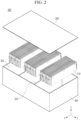
- FIG. 2 is an exploded view of a battery pack according to an embodiment of the present invention.
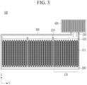
- FIG. 3 shows a cross-section of the battery pack of FIG. 2 in an assembled state.
- a configuration of a heat exchanger coupled to the battery pack of FIG. 2 is shown together.
- a battery pack 100 includes a battery pack frame 200 in which an accommodating portion 201 accommodating a single battery cell laminate 110 is formed in plural, a plurality of battery cell laminates 110 respectively accommodated in the accommodating portions 201, a coolant 410 filled in the accommodating portion, and a heat exchanger 400 that directly liquefies a vaporized coolant through communication with the plurality of accommodating portions.
- the battery cell laminate 110 may be formed by stacking a plurality of battery cells 111 in one direction.
- each battery cell 111 may be a pouch-type battery cell, but is not limited thereto.
- an additional member for electrical connection between the battery cell laminate 110 and the external configuration may be included, and a detailed description thereof will be omitted here.
- the battery cell laminate 110 may be directly accommodated in the accommodating portion 201 formed in the battery pack frame 200 without a separate accommodating member such as a module case.
- each accommodating portion 201 may be separated and partitioned by a partitioning wall 210.
- the coolant 410 is filled together with the battery cell laminate 110.
- the coolant 410 may be filled such that the battery cell laminate 110 is submerged as shown in the drawing. According to such a configuration, rapid cooling is possible because the entire battery cell laminate 110 is in contact with the coolant 410.
- vaporization of the coolant 410 can be actively performed, and thus cooling efficiency can be further increased.
- the coolant 410 is a component filled in the accommodating portion 201 and can be used without particular limitation as long as it has excellent cooling properties and insulating properties. For example, insulated cooling water or antifreeze that can maximize cooling efficiency due to high latent heat can be used.
- the coolant 410 is filled inside each of the accommodating portions 201 partitioned by the partitioning wall 210.
- an upper portion of the partitioning wall 210 is formed so as to not contact an upper plate 300 forming an upper portion of the battery pack 100 such that a space between the accommodating portion 201 and the upper plate 300 is not partitioned by the accommodating portion 201 and may be disposed to form one space. Accordingly, when the coolant 410 included in each accommodating portion 201 is vaporized, it is liquefied again through one heat exchanger 400 to be accommodated in the accommodating portion 201.
- the upper plate 300 covers the upper portion of the battery pack 100 and can be combined with the battery pack frame 200 by a method such as welding.
- a part of the upper plate 300 is provided with a passage 310 communicating with the inside of the battery pack frame 200, and the passage 310 may be formed to be connected to the heat exchanger 400. That is, the plurality of accommodating portions 201 are connected to each other through a separation space under the upper plate 300, and the heat exchanger 400 communicates with the separation space through the passage 310 such that the plurality of accommodating portions 201 may be formed to be connected with one heat exchanger 400.
- the heat generated in the battery cell 10 is transferred through the bottom surface of the module frame 20 through the thermal conductive adhesive layer 40 at the bottom, and transferred to the thermal interface material layer 50 and the battery pack frame 30 below it such that the heat transfer structure and path are complicated and the efficiency is insignificant.
- the heat generated in the battery cell 111 is effectively transferred through the coolant 410, rapid and efficient cooling can be achieved.
- separate heat transfer structures such as the thermal conductive adhesive, the module frame, and the thermal interface material layer can all be deleted, material cost reduction and weight reduction can be realized.
- coolant 410 boils and vaporizes, and due to the heat of vaporization at this time, it is possible to suppress the rapid temperature rise of the battery cell 111.
- the coolant 410 not only suppresses the temperature rise of the battery cell laminate 110 through vaporization, but also simultaneously blocks oxygen supply to the battery cell 111, and thus even though the temperature rises rapidly in the battery cell 111, the risk of ignition and explosion can be prevented.
- the vaporized coolant 410 moves to the heat exchanger 400 and is cooled in the heat exchanger 400 by contacting the heat exchanger 400.
- the heat exchanger 400 itself is in the form of a flow path containing a refrigerant inside, or may be formed of a cooling fin, and is not particularly limited as long as it can be liquefied in contact with vaporized coolant 410.
- the coolant 410 liquefied again by cooling in the heat exchanger 400 moves to the cell side, that is, the accommodating portion 201 again. With such a configuration, it is possible to automatically achieve circulation of the coolant 410 without a separate circulation device (e.g., a flow path in the battery pack or a circulation driving unit for moving the fluid again).
- the cost and weight can be reduced by eliminating the complex heat transfer structure, and the battery cell laminate can be cooled quickly and efficiently without the complex heat transfer structure.
- the coolant 410 can circulate through liquefaction and vaporization of the coolant 410 without a separate circulation structure for circulation of the coolant 410, a simple cooling function can be realized.
- FIG. 4 is a cross-sectional view of a battery pack according to another embodiment of the present invention.
- a battery pack 100' according to another embodiment is the same as the battery pack 100 of the above-described embodiment, except for a configuration of a heat exchanger, and thus the duplicated description will be omitted.
- a heat exchanger 400' in the present embodiment is formed in the form of a cooling plate disposed between an upper plate 300 and an accommodating portion 201. That is, by forming the heat exchanger 400' with a cooling plate having a plurality of cooling fins, it can be disposed and fixed to a lower part of the upper plate 300'. Alternatively, without being limited thereto, it is also possible to configure the upper plate 300' itself as a cooling plate.
- Liquefaction of a vaporized coolant 410 can be quickly carried out over a wide area by disposing the heat exchanger 400' in the form of a cooling plate over the entire upper part of a plurality of accommodating portions 201, and accordingly, cooling efficiency of a battery cell laminate 110 can be improved and circulation efficiency of the coolant 410 can also be improved.
- the material cost of the battery pack and the overall weight of the battery pack can be reduced by enabling the coolant to transfer the heat generated in the battery cell laminate to the outside quickly and efficiently without a complicated heat transfer structure.
- the circulation of the coolant can be carried out by forming the vaporization and liquefaction of the coolant to be repeated in the battery pack without including a separate circulation structure for the circulation of the coolant used.
- the battery pack can be applied to various devices.
- a device may be applied to transportation means such as an electric bicycle, electric vehicle, hybrid vehicle, etc., but the present invention is not limited thereto and is applicable to various devices that can use a battery module, to which the scope of the present invention also belongs.
Landscapes
- Chemical & Material Sciences (AREA)
- Chemical Kinetics & Catalysis (AREA)
- Electrochemistry (AREA)
- General Chemical & Material Sciences (AREA)
- Engineering & Computer Science (AREA)
- Manufacturing & Machinery (AREA)
- Secondary Cells (AREA)
- Battery Mounting, Suspending (AREA)
Abstract
Description
- This application claims priority to and the benefit of
Korean Patent Application No. 10-2020-0170440 filed in the Korean Intellectual Property Office on December 8, 2020 - The present invention relates to a battery pack and a device including the same, and it relates to a battery pack that can prevent fire and transmit heat efficiently, and a device including the same.
- In modern society, as the use of portable devices, such as mobile phones, notebook computers, camcorders, and digital cameras, has become commonplace, the development of technologies related to the mobile devices has become active. Further, a rechargeable secondary battery is a measure to solve the air pollution of existing gasoline vehicles that use fossil fuels, and is used as a power source of an Electric Vehicle (EV), a Hybrid Electric Vehicle (HEV), a Plug-in Hybrid Electric Vehicle (P-HEV), and the like, so that the need for development of the secondary battery is also increasing.
- In the case of a rechargeable battery used in small devices, 2 to 3 battery cells are disposed, but in the case of a rechargeable battery used in a medium or large device such as an automobile, a battery module in which a plurality of battery cells are electrically connected is used.
- In the case of a battery module used in such a medium-large device, a plurality of battery cells are electrically connected in series to provide a greater capacity than a specific value required by the device, and in this case, the stability of the rechargeable battery itself varies depending on a method of connecting a plurality of battery cells and a method of fixing them.
- In particular, in a rechargeable battery with increased capacity as described above, a method of cooling the battery is important in order to prevent a problem due to overheating of the battery. It is necessary to efficiently dissipate the heat inside the battery, and for dissipating the heat of the rechargeable battery, there is a method of applying a thermal interface material (TIM) to the surface that is coupled to the rechargeable battery. The thermal interface material (TIM) is also called a thermal interface material, and in a heat transfer path, a contact area of the heat transfer surface is adjusted by filling the material between each surface, and accordingly, the thermal resistance can be controlled by controlling the path of heat transfer,
-
FIG. 1 is a cross-sectional view of a part of a conventional battery pack. - Referring to
FIG. 1 , aconventional battery pack 1 includes a battery module formed by accommodating a battery cell formed by laminating a plurality ofbattery cells 10 in amodule frame 20, and abattery pack frame 30 supporting the battery module. In this case, a thermal conductiveadhesive layer 40 is formed between thebattery cell 10 and themodule frame 20 for heat dissipation, and a thermalinterface material layer 50 is formed between themodule frame 20 and thebattery pack frame 30. In addition, in thebattery pack frame 30, aflow path 31 through which a refrigerant flows may be formed to improve cooling performance. - In such a structure, the heat generated in the
battery cell 10 is transferred to the thermalinterface material layer 50 through thealuminum module frame 20 through the lower thermal conductiveadhesive layer 40 in a lower portion, and then is discharged through thebattery pack frame 30 to the outside, thereby cooling thebattery cell 10. - However, in this case, the path through which heat is discharged to the outside is complicated, and additional heat transfer materials that can transfer heat between the cell, the module frame, and the battery pack frame are required, and thus there are problems that rapid cooling is difficult, the weight of the entire battery pack increases, and the structure becomes complicated due to the increase in configuration.
- Embodiments of the present invention are proposed to solve the above problems, and a battery pack that can prevent fire by efficiently transferring heat generated inside the secondary battery and cooling it quickly, and reduce material cost and weight by excluding unnecessary heat transfer structures can be provided.
- However, the problems to be solved by the embodiments of the present invention are not limited to the above-described problems and may be variously expanded in the range of the technical ideas included in the present invention.
- A battery pack according to an embodiment of the present invention includes: a battery pack frame including a plurality of accommodating portions; a plurality of battery cell laminates accommodated in a respective one of the plurality of accommodating portions; a coolant filled in the plurality of accommodating portions; and a heat exchanger that liquefies the coolant that is vaporized by communicating with the plurality of accommodating portions.
- The coolant may be a liquid with insulating characteristics.
- The plurality of battery cell laminates may directly contact the coolant.
- The coolant that is vaporized may directly contact the heat exchanger.
- The coolant that is liquefied may bereturned the plurality of accommodating portions.
- The heat exchanger may communicate with the plurality of accommodating portions through a passage formed by an upper plate covering the plurality of accommodating portions.
- The heat exchanger may be a cooling plate formed between an upper plate covering the plurality of accommodating portions and the plurality of accommodating portions.
- The battery pack may further include an upper plate that covers the plurality of accommodating portions, wherein the plurality of accommodating portions are separated by at least one partitioning wall, and a separation space exists between the at least one partitioning wall and the upper plate.
- The heat exchanger may communicate with the separation space.
- A device according to another embodiment of the present invention includes the above-described battery pack.
- According to the embodiments of the present invention, it is possible to cool the battery cell by directly accommodating coolant inside the battery pack, and rapid cooling is possible, and the material cost and weight of the entire battery pack can be reduced by eliminating unnecessary heat transfer structures.
-
-
FIG. 1 is a cross-sectional view of a part of a conventional battery pack. -
FIG. 2 is an exploded view of a battery pack according to an embodiment of the present invention. -
FIG. 3 shows a cross-section of the battery pack ofFIG. 2 in an assembled state. -
FIG. 4 is a cross-sectional view of a battery pack according to another embodiment of the present invention. - Hereinafter, with reference to the accompanying drawing, various embodiments of the present invention will be described in detail such that a person of an ordinary skill can easily practice it in the technical field to which the present invention belongs. The present invention may be implemented in several different forms and is not limited to the embodiments described herein.
- The drawings and description are to be regarded as illustrative in nature and not restrictive. Like reference numerals designate like elements throughout the specification.
- In the drawings, size and thickness of each element are arbitrarily illustrated for convenience of description, and the present invention is not necessarily limited to as illustrated in the drawings. In the drawings, the thickness of layers, films, panels, regions, etc., are exaggerated for clarity. In addition, the drawing, for convenience of explanation, the thickness of some layers and regions is exaggerated.
- It will be understood that when an element such as a layer, film, region, or substrate is referred to as being "on" another element, it can be directly on the other element or intervening elements may also be present. In contrast, when an element is referred to as being "directly on" another element, there are no intervening elements present. Further, throughout the specification, the word "on" a target element will be understood to be positioned above or below the target element, and will not necessarily be understood to be positioned "at an upper side" based on an opposite to gravity direction.
- In addition, unless explicitly described to the contrary, the word "comprise", and variations such as "comprises" or "comprising", will be understood to imply the inclusion of stated elements but not the exclusion of any other elements.
- Further, throughout the specification, the phrase "on a plane" means viewing a target portion from the top, and the phrase "on a cross-section" means viewing a cross-section formed by vertically cutting a target portion from the side.
- Hereinafter, referring to
FIG. 2 andFIG. 3 , a battery pack according to an embodiment of the present invention will be described. -
FIG. 2 is an exploded view of a battery pack according to an embodiment of the present invention.FIG. 3 shows a cross-section of the battery pack ofFIG. 2 in an assembled state. In particular, inFIG. 3 , a configuration of a heat exchanger coupled to the battery pack ofFIG. 2 is shown together. - As shown in
FIG. 2 , abattery pack 100 according to an embodiment of the present invention includes abattery pack frame 200 in which anaccommodating portion 201 accommodating a singlebattery cell laminate 110 is formed in plural, a plurality ofbattery cell laminates 110 respectively accommodated in theaccommodating portions 201, acoolant 410 filled in the accommodating portion, and aheat exchanger 400 that directly liquefies a vaporized coolant through communication with the plurality of accommodating portions. - The
battery cell laminate 110 may be formed by stacking a plurality ofbattery cells 111 in one direction. In this case, eachbattery cell 111 may be a pouch-type battery cell, but is not limited thereto. In addition, although not shown, an additional member for electrical connection between thebattery cell laminate 110 and the external configuration may be included, and a detailed description thereof will be omitted here. - The
battery cell laminate 110 may be directly accommodated in theaccommodating portion 201 formed in thebattery pack frame 200 without a separate accommodating member such as a module case. In this case, eachaccommodating portion 201 may be separated and partitioned by a partitioningwall 210. In theaccommodating portion 201, thecoolant 410 is filled together with thebattery cell laminate 110. Thecoolant 410 may be filled such that thebattery cell laminate 110 is submerged as shown in the drawing. According to such a configuration, rapid cooling is possible because the entirebattery cell laminate 110 is in contact with thecoolant 410. In addition, as described later, when a temperature rises above a certain level, vaporization of thecoolant 410 can be actively performed, and thus cooling efficiency can be further increased. - The
coolant 410 is a component filled in theaccommodating portion 201 and can be used without particular limitation as long as it has excellent cooling properties and insulating properties. For example, insulated cooling water or antifreeze that can maximize cooling efficiency due to high latent heat can be used. Thecoolant 410 is filled inside each of theaccommodating portions 201 partitioned by thepartitioning wall 210. - In this case, an upper portion of the
partitioning wall 210 is formed so as to not contact anupper plate 300 forming an upper portion of thebattery pack 100 such that a space between theaccommodating portion 201 and theupper plate 300 is not partitioned by theaccommodating portion 201 and may be disposed to form one space. Accordingly, when thecoolant 410 included in eachaccommodating portion 201 is vaporized, it is liquefied again through oneheat exchanger 400 to be accommodated in theaccommodating portion 201. - The
upper plate 300 covers the upper portion of thebattery pack 100 and can be combined with thebattery pack frame 200 by a method such as welding. In this case, as shown inFIG. 3 , a part of theupper plate 300 is provided with apassage 310 communicating with the inside of thebattery pack frame 200, and thepassage 310 may be formed to be connected to theheat exchanger 400. That is, the plurality ofaccommodating portions 201 are connected to each other through a separation space under theupper plate 300, and theheat exchanger 400 communicates with the separation space through thepassage 310 such that the plurality ofaccommodating portions 201 may be formed to be connected with oneheat exchanger 400. - In the present embodiment, when heat is generated in the
battery cell laminate 110 included in theaccommodating portion 201, heat is transferred to thecoolant 410 in direct contact with thebattery cell laminate 110 to be cooled. In particular, conventionally, as described inFIG. 1 , the heat generated in thebattery cell 10 is transferred through the bottom surface of themodule frame 20 through the thermal conductiveadhesive layer 40 at the bottom, and transferred to the thermalinterface material layer 50 and thebattery pack frame 30 below it such that the heat transfer structure and path are complicated and the efficiency is insignificant. However, in the present embodiment, since the heat generated in thebattery cell 111 is effectively transferred through thecoolant 410, rapid and efficient cooling can be achieved. In addition, since separate heat transfer structures such as the thermal conductive adhesive, the module frame, and the thermal interface material layer can all be deleted, material cost reduction and weight reduction can be realized. - In addition, when the temperature of the
battery cell laminate 110 rises rapidly,coolant 410 boils and vaporizes, and due to the heat of vaporization at this time, it is possible to suppress the rapid temperature rise of thebattery cell 111. In addition, thecoolant 410 not only suppresses the temperature rise of thebattery cell laminate 110 through vaporization, but also simultaneously blocks oxygen supply to thebattery cell 111, and thus even though the temperature rises rapidly in thebattery cell 111, the risk of ignition and explosion can be prevented. - The vaporized
coolant 410 moves to theheat exchanger 400 and is cooled in theheat exchanger 400 by contacting theheat exchanger 400. In this case, theheat exchanger 400 itself is in the form of a flow path containing a refrigerant inside, or may be formed of a cooling fin, and is not particularly limited as long as it can be liquefied in contact with vaporizedcoolant 410. Thecoolant 410 liquefied again by cooling in theheat exchanger 400 moves to the cell side, that is, theaccommodating portion 201 again. With such a configuration, it is possible to automatically achieve circulation of thecoolant 410 without a separate circulation device (e.g., a flow path in the battery pack or a circulation driving unit for moving the fluid again). - As described above, according to the present embodiment, the cost and weight can be reduced by eliminating the complex heat transfer structure, and the battery cell laminate can be cooled quickly and efficiently without the complex heat transfer structure. In addition, since the
coolant 410 can circulate through liquefaction and vaporization of thecoolant 410 without a separate circulation structure for circulation of thecoolant 410, a simple cooling function can be realized. - Next, another embodiment of the present invention will be described with reference to
FIG. 4 . -
FIG. 4 is a cross-sectional view of a battery pack according to another embodiment of the present invention. - A battery pack 100' according to another embodiment is the same as the
battery pack 100 of the above-described embodiment, except for a configuration of a heat exchanger, and thus the duplicated description will be omitted. - As shown in
FIG. 4 , a heat exchanger 400' in the present embodiment is formed in the form of a cooling plate disposed between anupper plate 300 and anaccommodating portion 201. That is, by forming the heat exchanger 400' with a cooling plate having a plurality of cooling fins, it can be disposed and fixed to a lower part of the upper plate 300'. Alternatively, without being limited thereto, it is also possible to configure the upper plate 300' itself as a cooling plate. - Liquefaction of a vaporized
coolant 410 can be quickly carried out over a wide area by disposing the heat exchanger 400' in the form of a cooling plate over the entire upper part of a plurality ofaccommodating portions 201, and accordingly, cooling efficiency of abattery cell laminate 110 can be improved and circulation efficiency of thecoolant 410 can also be improved. - As described above, according to the present invention, the material cost of the battery pack and the overall weight of the battery pack can be reduced by enabling the coolant to transfer the heat generated in the battery cell laminate to the outside quickly and efficiently without a complicated heat transfer structure. In addition, the circulation of the coolant can be carried out by forming the vaporization and liquefaction of the coolant to be repeated in the battery pack without including a separate circulation structure for the circulation of the coolant used.
- The battery pack can be applied to various devices. Such a device may be applied to transportation means such as an electric bicycle, electric vehicle, hybrid vehicle, etc., but the present invention is not limited thereto and is applicable to various devices that can use a battery module, to which the scope of the present invention also belongs.
- While this invention has been described in connection with what is presently considered to be practical embodiments, it is to be understood that the invention is not limited to the disclosed embodiments. On the contrary, it is intended to cover various modifications and equivalent arrangements included within the spirit and scope of the appended claims.
-
- 100: battery pack
- 110: battery cell laminate
- 111: battery cell
- 200: battery pack frame
- 201: accommodating portion
- 210: partitioning wall
- 300: upper plate
- 310: passage
- 400, 400': heat exchanger
- 410: coolant
Claims (10)
- A battery pack comprising:a battery pack frame including a plurality of accommodating portions;a plurality of battery cell laminates accommodated in a respective one of the plurality of accommodating portions;a coolant filled in the plurality of accommodating portions; anda heat exchanger that liquefies the coolant that is vaporized by communicating with the plurality of accommodating portions.
- The battery pack of claim 1, wherein the coolant is a liquid with insulating characteristics.
- The battery pack of claim 1, wherein the plurality of battery cell laminates directly contacts the coolant.
- The battery pack of claim 1, wherein the coolant that is vaporized directly contacts the heat exchanger.
- The battery pack of claim 1, wherein the coolant that is liquefied is returned to the plurality of accommodating portions.
- The battery pack of claim 1, wherein the heat exchanger communicates with the plurality of accommodating portions through a passage formed by an upper plate covering the plurality of accommodating portions.
- The battery pack of claim 1, wherein the heat exchanger is a cooling plate formed between an upper plate covering the plurality of accommodating portions and the plurality of accommodating portions.
- The battery pack of claim 1, further comprising an upper plate that covers the plurality of accommodating portions,
wherein the plurality of accommodating portions are separated by at least one partitioning wall, and a separation space exists between the at least one partitioning wall and the upper plate. - The battery pack of claim 8, wherein the heat exchanger communicates with the separation space.
- A device comprising the battery pack of claim 1.
Applications Claiming Priority (2)
| Application Number | Priority Date | Filing Date | Title |
|---|---|---|---|
| KR1020200170440A KR20220081027A (en) | 2020-12-08 | 2020-12-08 | Battery pack and device including the same |
| PCT/KR2021/018365 WO2022124731A1 (en) | 2020-12-08 | 2021-12-06 | Battery pack, and device including same |
Publications (2)
| Publication Number | Publication Date |
|---|---|
| EP4175024A1 true EP4175024A1 (en) | 2023-05-03 |
| EP4175024A4 EP4175024A4 (en) | 2024-05-15 |
Family
ID=81973838
Family Applications (1)
| Application Number | Title | Priority Date | Filing Date |
|---|---|---|---|
| EP21903777.7A Pending EP4175024A4 (en) | 2020-12-08 | 2021-12-06 | BATTERY PACK AND DEVICE COMPRISING IT |
Country Status (6)
| Country | Link |
|---|---|
| US (1) | US20230238612A1 (en) |
| EP (1) | EP4175024A4 (en) |
| JP (1) | JP7556591B2 (en) |
| KR (1) | KR20220081027A (en) |
| CN (1) | CN115917839A (en) |
| WO (1) | WO2022124731A1 (en) |
Families Citing this family (2)
| Publication number | Priority date | Publication date | Assignee | Title |
|---|---|---|---|---|
| EP4376189A4 (en) * | 2022-07-20 | 2025-09-10 | Lg Energy Solution Ltd | BATTERY PACK AND CELL BLOCK CONTAINED THEREIN AND VEHICLE THEREOF |
| KR102507145B1 (en) * | 2022-10-26 | 2023-03-07 | 주식회사 서연이화 | supercapacitor pack with improved heat dissipation |
Family Cites Families (15)
| Publication number | Priority date | Publication date | Assignee | Title |
|---|---|---|---|---|
| JPS5111330B2 (en) * | 1973-07-11 | 1976-04-10 | ||
| JP4123541B2 (en) * | 1997-07-02 | 2008-07-23 | 株式会社デンソー | Battery cooling device |
| US20100104927A1 (en) * | 2008-10-29 | 2010-04-29 | Scott Albright | Temperature-controlled battery configuration |
| DE102009000066A1 (en) * | 2009-01-08 | 2010-07-15 | Robert Bosch Gmbh | Method for tempering battery cells of battery system, involves executing evaporating cooling of battery cells of battery system with heat transfer medium |
| DE102009006426A1 (en) * | 2009-01-28 | 2010-07-29 | Li-Tec Battery Gmbh | Battery with housing |
| JP2013062023A (en) * | 2010-02-23 | 2013-04-04 | Bosch Corp | Battery pack |
| JP2014026825A (en) * | 2012-07-26 | 2014-02-06 | Mitsubishi Motors Corp | Battery cooling system |
| KR20150117521A (en) * | 2014-04-10 | 2015-10-20 | (주)아이비티 | Marine battery cooling apparatus using heat pipes |
| EP2950379A1 (en) * | 2014-05-30 | 2015-12-02 | Siemens Aktiengesellschaft | Electrical energy storage device |
| KR101747509B1 (en) * | 2014-12-31 | 2017-06-19 | 주식회사 포스코아이씨티 | Battery Conditioning System of Energy Storage System using Heat Exchanging Medium |
| JP6604442B2 (en) * | 2016-09-09 | 2019-11-13 | 株式会社デンソー | Equipment temperature controller |
| CA3055897A1 (en) * | 2017-03-09 | 2018-09-13 | Zuta-Car Ltd. | Systems and methods for thermal regulation |
| KR102169631B1 (en) * | 2017-03-21 | 2020-10-23 | 주식회사 엘지화학 | Battery module, battery pack comprising the battery module and vehicle comprising the battery pack |
| DE102017119467B4 (en) * | 2017-08-25 | 2020-01-23 | Dr. Ing. H.C. F. Porsche Aktiengesellschaft | Battery device for an at least partially electrically operated motor vehicle |
| US11094977B2 (en) * | 2019-08-30 | 2021-08-17 | Baidu Usa Llc | Battery thermal management system with passive battery pack cooling |
-
2020
- 2020-12-08 KR KR1020200170440A patent/KR20220081027A/en active Pending
-
2021
- 2021-12-06 WO PCT/KR2021/018365 patent/WO2022124731A1/en not_active Ceased
- 2021-12-06 EP EP21903777.7A patent/EP4175024A4/en active Pending
- 2021-12-06 CN CN202180044875.XA patent/CN115917839A/en active Pending
- 2021-12-06 JP JP2022575259A patent/JP7556591B2/en active Active
- 2021-12-06 US US18/010,958 patent/US20230238612A1/en active Pending
Also Published As
| Publication number | Publication date |
|---|---|
| JP2023528521A (en) | 2023-07-04 |
| EP4175024A4 (en) | 2024-05-15 |
| US20230238612A1 (en) | 2023-07-27 |
| KR20220081027A (en) | 2022-06-15 |
| JP7556591B2 (en) | 2024-09-26 |
| CN115917839A (en) | 2023-04-04 |
| WO2022124731A1 (en) | 2022-06-16 |
Similar Documents
| Publication | Publication Date | Title |
|---|---|---|
| JP7102020B2 (en) | Battery module | |
| JP7155168B2 (en) | Power supply and electric vehicle equipped with power supply | |
| KR101326086B1 (en) | Battery Module with Compact Structure and Excellent Heat Radiation Characteristics and Middle or Large-sized Battery Pack Employed with the Same | |
| US12548815B2 (en) | Battery module | |
| JP2023143936A (en) | Battery packs and devices containing them | |
| US10283822B2 (en) | Battery module assembly | |
| US12266775B2 (en) | Battery module | |
| US12548822B2 (en) | Battery pack and device including the same | |
| JP2023501680A (en) | Battery modules and battery packs containing the same | |
| KR102863723B1 (en) | Can type battery module comprising immersion cooling part | |
| KR102821615B1 (en) | Battery module and battery pack including the same | |
| US20230238612A1 (en) | Battery pack, and device including the same | |
| KR20230170552A (en) | Dual cooling battery pack and vehicle including the same | |
| KR20240064712A (en) | Battery and its manufacturing method and electrical device | |
| KR20210042584A (en) | Battery module and battery pack including the same | |
| JP7744089B2 (en) | Battery module and battery pack including said battery module | |
| CN116018714A (en) | Battery module and battery pack including the same | |
| KR102683482B1 (en) | Battery Pack | |
| US20240113357A1 (en) | Battery pack and device including the same | |
| KR102193166B1 (en) | Battery module | |
| KR20220170339A (en) | Battery module and battery pack including the same | |
| KR20220133022A (en) | Battery module and battery pack including the same | |
| KR20220082297A (en) | Battery module and battery pack including the same | |
| KR102887874B1 (en) | Cooling device and battery cell stack comprising the same | |
| US20220376328A1 (en) | Secondary battery cooling structure |
Legal Events
| Date | Code | Title | Description |
|---|---|---|---|
| STAA | Information on the status of an ep patent application or granted ep patent |
Free format text: STATUS: THE INTERNATIONAL PUBLICATION HAS BEEN MADE |
|
| PUAI | Public reference made under article 153(3) epc to a published international application that has entered the european phase |
Free format text: ORIGINAL CODE: 0009012 |
|
| STAA | Information on the status of an ep patent application or granted ep patent |
Free format text: STATUS: REQUEST FOR EXAMINATION WAS MADE |
|
| 17P | Request for examination filed |
Effective date: 20230126 |
|
| AK | Designated contracting states |
Kind code of ref document: A1 Designated state(s): AL AT BE BG CH CY CZ DE DK EE ES FI FR GB GR HR HU IE IS IT LI LT LU LV MC MK MT NL NO PL PT RO RS SE SI SK SM TR |
|
| DAV | Request for validation of the european patent (deleted) | ||
| DAX | Request for extension of the european patent (deleted) | ||
| A4 | Supplementary search report drawn up and despatched |
Effective date: 20240416 |
|
| RIC1 | Information provided on ipc code assigned before grant |
Ipc: H01M 10/6556 20140101ALI20240410BHEP Ipc: H01M 50/211 20210101ALI20240410BHEP Ipc: H01M 10/613 20140101ALI20240410BHEP Ipc: H01M 10/647 20140101ALI20240410BHEP Ipc: H01M 10/6568 20140101ALI20240410BHEP Ipc: H01M 10/6569 20140101AFI20240410BHEP |
|
| STAA | Information on the status of an ep patent application or granted ep patent |
Free format text: STATUS: EXAMINATION IS IN PROGRESS |
|
| 17Q | First examination report despatched |
Effective date: 20250805 |
|
| GRAP | Despatch of communication of intention to grant a patent |
Free format text: ORIGINAL CODE: EPIDOSNIGR1 |
|
| STAA | Information on the status of an ep patent application or granted ep patent |
Free format text: STATUS: GRANT OF PATENT IS INTENDED |
|
| INTG | Intention to grant announced |
Effective date: 20260317 |