EP4174899A1 - Relay and battery system comprising same - Google Patents
Relay and battery system comprising same Download PDFInfo
- Publication number
- EP4174899A1 EP4174899A1 EP21864596.8A EP21864596A EP4174899A1 EP 4174899 A1 EP4174899 A1 EP 4174899A1 EP 21864596 A EP21864596 A EP 21864596A EP 4174899 A1 EP4174899 A1 EP 4174899A1
- Authority
- EP
- European Patent Office
- Prior art keywords
- magnets
- relay
- switching device
- current
- magnet
- Prior art date
- Legal status (The legal status is an assumption and is not a legal conclusion. Google has not performed a legal analysis and makes no representation as to the accuracy of the status listed.)
- Pending
Links
Images





Classifications
-
- H—ELECTRICITY
- H01—ELECTRIC ELEMENTS
- H01H—ELECTRIC SWITCHES; RELAYS; SELECTORS; EMERGENCY PROTECTIVE DEVICES
- H01H50/00—Details of electromagnetic relays
- H01H50/16—Magnetic circuit arrangements
- H01H50/18—Movable parts of magnetic circuits, e.g. armature
- H01H50/24—Parts rotatable or rockable outside coil
-
- H—ELECTRICITY
- H01—ELECTRIC ELEMENTS
- H01H—ELECTRIC SWITCHES; RELAYS; SELECTORS; EMERGENCY PROTECTIVE DEVICES
- H01H50/00—Details of electromagnetic relays
- H01H50/64—Driving arrangements between movable part of magnetic circuit and contact
- H01H50/643—Driving arrangements between movable part of magnetic circuit and contact intermediate part performing a rotating or pivoting movement
-
- H—ELECTRICITY
- H01—ELECTRIC ELEMENTS
- H01H—ELECTRIC SWITCHES; RELAYS; SELECTORS; EMERGENCY PROTECTIVE DEVICES
- H01H9/00—Details of switching devices, not covered by groups H01H1/00 - H01H7/00
- H01H9/30—Means for extinguishing or preventing arc between current-carrying parts
- H01H9/44—Means for extinguishing or preventing arc between current-carrying parts using blow-out magnet
- H01H9/443—Means for extinguishing or preventing arc between current-carrying parts using blow-out magnet using permanent magnets
-
- H—ELECTRICITY
- H01—ELECTRIC ELEMENTS
- H01M—PROCESSES OR MEANS, e.g. BATTERIES, FOR THE DIRECT CONVERSION OF CHEMICAL ENERGY INTO ELECTRICAL ENERGY
- H01M10/00—Secondary cells; Manufacture thereof
- H01M10/42—Methods or arrangements for servicing or maintenance of secondary cells or secondary half-cells
-
- H—ELECTRICITY
- H01—ELECTRIC ELEMENTS
- H01M—PROCESSES OR MEANS, e.g. BATTERIES, FOR THE DIRECT CONVERSION OF CHEMICAL ENERGY INTO ELECTRICAL ENERGY
- H01M10/00—Secondary cells; Manufacture thereof
- H01M10/42—Methods or arrangements for servicing or maintenance of secondary cells or secondary half-cells
- H01M10/425—Structural combination with electronic components, e.g. electronic circuits integrated to the outside of the casing
-
- H—ELECTRICITY
- H02—GENERATION; CONVERSION OR DISTRIBUTION OF ELECTRIC POWER
- H02J—ELECTRIC POWER NETWORKS; CIRCUIT ARRANGEMENTS OR SYSTEMS FOR SUPPLYING OR DISTRIBUTING ELECTRIC POWER; SYSTEMS FOR STORING ELECTRIC ENERGY
- H02J7/00—Circuit arrangements for charging or discharging batteries or for supplying loads from batteries
- H02J7/50—Circuit arrangements for charging or discharging batteries or for supplying loads from batteries acting upon multiple batteries simultaneously or sequentially
-
- H—ELECTRICITY
- H02—GENERATION; CONVERSION OR DISTRIBUTION OF ELECTRIC POWER
- H02J—ELECTRIC POWER NETWORKS; CIRCUIT ARRANGEMENTS OR SYSTEMS FOR SUPPLYING OR DISTRIBUTING ELECTRIC POWER; SYSTEMS FOR STORING ELECTRIC ENERGY
- H02J7/00—Circuit arrangements for charging or discharging batteries or for supplying loads from batteries
- H02J7/60—Circuit arrangements for charging or discharging batteries or for supplying loads from batteries including safety or protection arrangements
-
- H—ELECTRICITY
- H02—GENERATION; CONVERSION OR DISTRIBUTION OF ELECTRIC POWER
- H02J—ELECTRIC POWER NETWORKS; CIRCUIT ARRANGEMENTS OR SYSTEMS FOR SUPPLYING OR DISTRIBUTING ELECTRIC POWER; SYSTEMS FOR STORING ELECTRIC ENERGY
- H02J7/00—Circuit arrangements for charging or discharging batteries or for supplying loads from batteries
- H02J7/855—Circuit arrangements for charging or discharging batteries or for supplying loads from batteries with circuits adapted for supplying loads from the battery
-
- H—ELECTRICITY
- H02—GENERATION; CONVERSION OR DISTRIBUTION OF ELECTRIC POWER
- H02K—DYNAMO-ELECTRIC MACHINES
- H02K7/00—Arrangements for handling mechanical energy structurally associated with dynamo-electric machines, e.g. structural association with mechanical driving motors or auxiliary dynamo-electric machines
- H02K7/10—Structural association with clutches, brakes, gears, pulleys or mechanical starters
- H02K7/116—Structural association with clutches, brakes, gears, pulleys or mechanical starters with gears
-
- H—ELECTRICITY
- H01—ELECTRIC ELEMENTS
- H01H—ELECTRIC SWITCHES; RELAYS; SELECTORS; EMERGENCY PROTECTIVE DEVICES
- H01H50/00—Details of electromagnetic relays
- H01H50/54—Contact arrangements
- H01H50/546—Contact arrangements for contactors having bridging contacts
-
- H—ELECTRICITY
- H02—GENERATION; CONVERSION OR DISTRIBUTION OF ELECTRIC POWER
- H02J—ELECTRIC POWER NETWORKS; CIRCUIT ARRANGEMENTS OR SYSTEMS FOR SUPPLYING OR DISTRIBUTING ELECTRIC POWER; SYSTEMS FOR STORING ELECTRIC ENERGY
- H02J7/00—Circuit arrangements for charging or discharging batteries or for supplying loads from batteries
- H02J7/60—Circuit arrangements for charging or discharging batteries or for supplying loads from batteries including safety or protection arrangements
- H02J7/663—Circuit arrangements for charging or discharging batteries or for supplying loads from batteries including safety or protection arrangements using battery or load disconnect circuits
-
- Y—GENERAL TAGGING OF NEW TECHNOLOGICAL DEVELOPMENTS; GENERAL TAGGING OF CROSS-SECTIONAL TECHNOLOGIES SPANNING OVER SEVERAL SECTIONS OF THE IPC; TECHNICAL SUBJECTS COVERED BY FORMER USPC CROSS-REFERENCE ART COLLECTIONS [XRACs] AND DIGESTS
- Y02—TECHNOLOGIES OR APPLICATIONS FOR MITIGATION OR ADAPTATION AGAINST CLIMATE CHANGE
- Y02E—REDUCTION OF GREENHOUSE GAS [GHG] EMISSIONS, RELATED TO ENERGY GENERATION, TRANSMISSION OR DISTRIBUTION
- Y02E60/00—Enabling technologies; Technologies with a potential or indirect contribution to GHG emissions mitigation
- Y02E60/10—Energy storage using batteries
Definitions
- the present disclosure relates to a relay and a battery system including the same.
- a relay is opened while a high current is flowing in a battery system, an arc occurs.
- a magnet is used to form the direction of the arc that occurs when the relay is opened while the high current flows in one direction into an outside of a contact terminal. This may improve the durability of the relay.
- the arc generated when the relay is opened while high current flows in the direction opposite to the one direction travels into an inside of the contact terminal. This may reduce the durability of the relay.
- the conventional battery system cannot increase both direction currents. That is, the battery system may increase current flowing in one direction, but cannot increase current flowing in the other direction.
- the present disclosure is to provide a relay that can improve the cycle-life of the contact terminal for current flowing in both directions by changing the magnetic field according to the direction of the current, and a battery system including the same.
- a battery system may include: a battery pack including a plurality of battery cells; and a relay including a first contact terminal connected to one end of the battery pack and a second contact terminal connected to an output terminal, and the relay may include a magnetic device that changes the magnetic field according to the direction of the current flowing between the first contact terminal and the second contact terminal.
- a relay includes: a switching device including a moving contact bar electrically connecting two contact terminals when a current flows through a coil; a magnetic device including the two magnets facing each other based on a virtual reference line connecting two contact terminals and surrounding the switching device; a rotation and supporting member positioned between a coupling interior circumference, which is some area of the interior circumference of the magnetic device, and some external circumferential surface of the switching device corresponding to the coupling interior circumference, so that the magnetic device is supported and rotated with respect to the switching device; and a current sensor that detects the direction of the current flowing between the two contact terminals, wherein the two magnets are rotated depending on the direction of the current.
- the relay may further include a fixing substrate coupled to the bottom surface of the switching device for fixing the switching device.
- the magnetic device may further include a magnet rotation part in which the two magnets are positioned to face each other on an upper surface and are fixed, and when the direction of the current is changed, the magnet rotation part may rotate to exchange the positions of the two magnets with respect to each other.
- the magnet rotation part may include a gear block including a plurality of gear teeth formed along the gear interior circumference, which is a part of the interior circumference of the magnet rotation part
- the relay may include a motor including a gear block of which the plurality of gear teeth are formed in a circular shape at the end of the shaft of the motor, and the gear block of the motor and the gear block of the magnet rotation part may be positioned close to each other so that the gear teeth thereof are engaged with each other.
- the relay may further include a motor driver for driving the motor for the magnet rotation part to rotate 180 degrees when the current direction is changed.
- Each of the two magnets may have a shape that leaves only the outer part of a predetermined thickness in a column having a sector-shaped cross-section, and the magnet rotation part may have a shape that leaves only the outer part of a predetermined thickness in a circular cylinder.
- an N-pole magnet When the current flows in the first direction, an N-pole magnet, one of the two magnets, may be positioned on one side with respect to the virtual reference line, and an S-pole magnet, the other of the two magnets, may be positioned on the other side with respect to the virtual reference line, and when the current flows in the second direction, the N-pole magnet may be positioned on the other side with respect to the virtual reference line, and the S-pole magnet may be positioned on the one side with respect to the virtual reference line.
- the rotation and supporting member may be implemented as a ball bearing.
- the relay and the battery system which can improve the cycle-life of the contact terminal for the currents of both directions by changing the magnetic field according to the direction of the current, are provided.
- FIG. 1 is a view showing a configuration of a battery system according to an exemplary embodiment.
- a battery system 1 includes a battery pack 10, a battery management system (BMS) 20, and a relay 40.
- FIG. 1 shows only one battery pack, but the invention is not limited thereto, and the battery system 1 may include two or more battery packs.
- two or more battery packs may be connected in series or in parallel, a plurality of battery packs that are connected in series may be connected in parallel, or a plurality of battery packs that are connected in parallel may be connected in series.
- the battery pack 10 includes a plurality of battery cells 11-15 connected in series.
- the battery pack 10 is illustrated as including five battery cells 11-15, but this is an example and the invention is not limited thereto.
- the BMS 20 is connected to a plurality of battery cells 11-15 to measure a cell voltage of a plurality of battery cells 11 to 15.
- the BMS 20 acquires a battery pack 10 voltage, a battery pack current, and a battery pack temperature.
- the BMS 20 may control the charging and discharging current of the battery pack 10 based on the cell voltage and the battery pack current of a plurality of battery cells 11-15, and control the cell balancing operation for a plurality of battery cells 11-15.
- the BMS 20 controls opening and closing of the relay 40 for the charging and discharging control of the battery pack 10.
- the BMS 20 generates a relay control signal RCS that controls the opening and closing of the relay 40 to be supplied to the relay 40.
- the relay 40 is opened and closed according to the relay control signal RCS and includes two contact terminals 41 and 42, the contact terminal 41 is connected to a positive electrode of the battery pack 10 through a line 31, and the contact terminal 42 is connected to an output terminal P+ through a line 32.
- the battery system 1 may further include a relay connected between a negative electrode of the battery pack 10 and an output terminal P-.
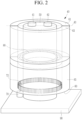
- FIG. 2 is a perspective view showing a relay according to an exemplary embodiment.
- the relay 40 includes a switching device 50, a magnetic device 60, a motor 70, a ball bearing 80, and a fixing substrate 90.
- the switching device 50 controls an electrical connection between the two contact terminals 41 and 42.
- the switching device 50 and the magnetic device 60 may be coupled by various rotation and supporting members.
- the rotation and supporting member may be a member supporting the switching device 50 and the magnetic device 60 so as to surround the switching device 50 with a distance to be rotational with respect to the fixed switching device 50, and allowing the magnetic device 60 to rotate around the switching device 50.
- the rotation and supporting member may be implemented with various types of bearings.
- a ball bearing 80 is shown as a rotation and supporting member, but the invention is not limited thereto.
- the coupling part 51 of the switching device 50 may be attached with the interior circumference of the ball bearing 80 by various coupling means.
- the magnetic device 60 includes two magnets 61 and 62, and a magnet rotation part 65.
- the two magnets 61 and 62 face each other based on a virtual reference line 43 connecting the two contact terminals 41 and 42, and surround the switching device 50.
- the two magnets 61 and 62 face each other and are fixed, and their positions are changed based on the virtual reference line 43 according to the rotation of the magnet rotation part 65.
- the magnet rotation part 65 may be rotated by the motor 70 to rotate the two magnets 61 and 62.
- the area 63 attached to the external circumferential surface of the ball bearing 80 is positioned.
- the bottom surface of the switching device 50 is fixed by bonding to the fixing substrate 90. Accordingly, when the motor 70 is driven, the magnet rotation part 65 rotates, and the two magnets 61 and 62 coupled to the magnet rotation part 65 also rotate.
- the structure illustrated in FIG. 2 is an example of a structure in which the positions of the two magnets 61 and 62 can be exchanged with respect to the virtual reference line 43.
- the present invention is not limited to the structure shown in FIG. 2 , and any one of various structures in which the positions of the two magnets 61 and 62 may be exchanged with respect to the virtual reference line 43 may be applied.
- FIG. 3 is a view only showing a switching device according to an exemplary embodiment.
- FIG. 4 is a view showing a cross-section of a switching device taken along a line A-A' in FIG. 3 .
- the switching device 50 is shown as a plunger type, but the invention is not limited thereto. It may also be applied to other types of switching devices in which arc occurs due to the relay opening.
- the switching device 50 includes contact terminals 41 and 42, a plunger 58, coils 45 and 46, a housing 55, and a current sensor 91.
- the housing 55 receives the configuration of the switching device 50, holds the contact terminals 41 and 42, and may be attached to the fixing substrate 90.
- the current sensor 91 is connected between two contact terminals 41 and 42, and may sense a direction of a current flowing between the two contact terminals 41 and 42.
- the current sensor 91 may be electrically connected to the lines 31 and 32 outside the switching device 50 to sense the direction of the current.
- the current sensor 91 may generate a signal IS indicating the direction of the sensed current and transmit it to the relay control unit 44.
- the plunger 58 includes a moving contact bar 56 and a shaft 57, and the shaft 57 is coupled to the moving contact bar 56 in the vertical direction and is positioned at the central passage 59, and may move along the central passage 59 by the magnetic field generated when the current flows in the coils 45 and 46.
- the coils 45 and 46 may be implemented as solenoids. That is, the coils 45 and 46 are wound to surround the central passage 59 so that a solenoid shape with a hollow shape may be implemented.
- the shaft 57 moves upward by the magnetic field generated when the current flows, and then the moving contact bar 56 is in contact with both contact terminals 41 and 42.
- the battery system 1 and the output terminal P+ are connected, and the current may flow to a device electrically connected between two output terminals P+ and P-, or the corresponding current may be supplied from the device.
- FIG. 5 is a view showing a magnetic device according to an exemplary embodiment.
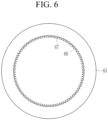
- FIG. 6 is a rear view of a magnetic device according to an exemplary embodiment.
- the magnetic device 60 includes the two magnets 61 and 62 and the magnet rotation part 65.
- Each of the two magnets 61 and 62 has a shape in which only the outer portion of a predetermined thickness d1 is left in a column having a cross-section of a sector shape
- the magnet rotation part 65 has a shape in which only the outer portion of a predetermined thickness d2 is left in a circular cylinder.
- the central angle (O) of the sector-shaped cross-section of each of the two magnets 61 and 62 may be greater than or equal to a predetermined angle and less than 180 degrees.
- the thickness d2 may be greater than or equal to the thickness d1.
- the magnet rotation part 65 includes a gear block 66 formed in a part (hereinafter referred to as "a gear interior circumference") 69 of the interior circumference.
- the gear block 66 includes a plurality of gear teeth (e.g., 67), and the plurality of gear teeth 67 are continuously formed along the gear interior circumference 69.
- the gear block 66 is rotated by the motor 70 so that the magnet rotation part 65 may be rotated.
- the magnet rotation part 65 is coupled to the switching device 50 fixed by the ball bearing 80, it rotates in place.
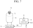
- FIG. 7 is a view showing a motor, a motor driver, and a relay control unit according to an exemplary embodiment.
- a gear block 72 in which a plurality of gear teeth are formed in a circular shape is coupled.
- the motor driver 73 is driven by supplying power to the motor 70 according to the motor driving signal MS supplied from the relay control unit 44.
- the gear block 72 of the shaft 71 and the gear block 66 of the magnet rotation part 65 are positioned close to each other so that the gear teeth may be engaged.
- the gear block 72 rotates around the shaft 71, a plurality of gear teeth of the gear block 72 and a plurality of gear teeth of the gear block 66 are sequentially engaged, and the magnet rotation part 65 rotates.
- the relay control unit 44 may determine a current direction according to the current detection signal IS, detect a time when the current is cut off according to the relay control signal RCS, and generate a motor driving signal MS.
- the relay control unit 44 may generate a control signal VC for controlling the switching device 50 according to the relay control signal RCS. Depending on the control signal VC, the voltage is supplied to the coils 45 and 46 or is cut off.
- FIG. 8 and FIG. 9 are views showing an operation of a magnetic device according to a direction of a current.
- the BMS 20 transmits the relay control signal RCS for opening the relay 40 to the relay control unit 44.
- the relay control unit 44 determines the direction in which the current I1 flows by the current detection signal IS.
- the arc occurs at the contact terminal in the direction outside the contact terminal, so they do not drive the motor 70.
- the BMS 20 transmits the relay control signal RCS that opens the relay 40 to the relay control unit 44.
- the relay control unit 44 determines the direction in which the current I2 flows by the current detection signal IS, and transmits the motor driving signal MS to the motor driver 73.
- the motor driver 73 drives the motor 70 to rotate the magnet rotation part 65 by 180 degrees according to the motor driving signal MS. Then, as shown in FIG. 9 , based on the virtual reference line 43, the N pole magnet 61 is positioned below, and the S pole magnet 62 is positioned above. Accordingly, even when the direction of the current I2 is opposite to the direction of the current 11, the arc is generated in the contact terminal in the direction outside the contact terminal.
Landscapes
- Engineering & Computer Science (AREA)
- Power Engineering (AREA)
- Physics & Mathematics (AREA)
- Electromagnetism (AREA)
- Chemical & Material Sciences (AREA)
- Manufacturing & Machinery (AREA)
- Chemical Kinetics & Catalysis (AREA)
- Electrochemistry (AREA)
- General Chemical & Material Sciences (AREA)
- Microelectronics & Electronic Packaging (AREA)
- Battery Mounting, Suspending (AREA)
- Relay Circuits (AREA)
- Charge And Discharge Circuits For Batteries Or The Like (AREA)
- Toys (AREA)
Abstract
Description
- This application claims priority to and the benefit of
Korean Patent Application No. 10-2020-0111252 filed in the Korean Intellectual Property Office on September 01, 2020 - The present disclosure relates to a relay and a battery system including the same.
- If a relay is opened while a high current is flowing in a battery system, an arc occurs. In a conventional art, a magnet is used to form the direction of the arc that occurs when the relay is opened while the high current flows in one direction into an outside of a contact terminal. This may improve the durability of the relay. However, the arc generated when the relay is opened while high current flows in the direction opposite to the one direction travels into an inside of the contact terminal. This may reduce the durability of the relay.
- Due to this limitation, the conventional battery system cannot increase both direction currents. That is, the battery system may increase current flowing in one direction, but cannot increase current flowing in the other direction.
- The present disclosure is to provide a relay that can improve the cycle-life of the contact terminal for current flowing in both directions by changing the magnetic field according to the direction of the current, and a battery system including the same.
- A battery system according to one aspect of the present invention may include: a battery pack including a plurality of battery cells; and a relay including a first contact terminal connected to one end of the battery pack and a second contact terminal connected to an output terminal, and the relay may include a magnetic device that changes the magnetic field according to the direction of the current flowing between the first contact terminal and the second contact terminal.
- A relay according to another aspect of the present invention includes: a switching device including a moving contact bar electrically connecting two contact terminals when a current flows through a coil; a magnetic device including the two magnets facing each other based on a virtual reference line connecting two contact terminals and surrounding the switching device; a rotation and supporting member positioned between a coupling interior circumference, which is some area of the interior circumference of the magnetic device, and some external circumferential surface of the switching device corresponding to the coupling interior circumference, so that the magnetic device is supported and rotated with respect to the switching device; and a current sensor that detects the direction of the current flowing between the two contact terminals, wherein the two magnets are rotated depending on the direction of the current.
- The relay may further include a fixing substrate coupled to the bottom surface of the switching device for fixing the switching device.
- The magnetic device may further include a magnet rotation part in which the two magnets are positioned to face each other on an upper surface and are fixed, and when the direction of the current is changed, the magnet rotation part may rotate to exchange the positions of the two magnets with respect to each other.
- The magnet rotation part may include a gear block including a plurality of gear teeth formed along the gear interior circumference, which is a part of the interior circumference of the magnet rotation part, the relay may include a motor including a gear block of which the plurality of gear teeth are formed in a circular shape at the end of the shaft of the motor, and the gear block of the motor and the gear block of the magnet rotation part may be positioned close to each other so that the gear teeth thereof are engaged with each other.
- The relay may further include a motor driver for driving the motor for the magnet rotation part to rotate 180 degrees when the current direction is changed.
- Each of the two magnets may have a shape that leaves only the outer part of a predetermined thickness in a column having a sector-shaped cross-section, and the magnet rotation part may have a shape that leaves only the outer part of a predetermined thickness in a circular cylinder.
- When the current flows in the first direction, an N-pole magnet, one of the two magnets, may be positioned on one side with respect to the virtual reference line, and an S-pole magnet, the other of the two magnets, may be positioned on the other side with respect to the virtual reference line, and when the current flows in the second direction, the N-pole magnet may be positioned on the other side with respect to the virtual reference line, and the S-pole magnet may be positioned on the one side with respect to the virtual reference line.
- The rotation and supporting member may be implemented as a ball bearing.
- The relay and the battery system, which can improve the cycle-life of the contact terminal for the currents of both directions by changing the magnetic field according to the direction of the current, are provided.
-
-
FIG. 1 is a view showing a configuration of a battery system according to an exemplary embodiment. -
FIG. 2 is a perspective view showing a relay according to an exemplary embodiment. -
FIG. 3 is a view only showing a switching device according to an exemplary embodiment. -
FIG. 4 is a view showing a cross-section of a switching device taken along a line A-A' inFIG. 3 . -
FIG. 5 is a view showing a magnetic device according to an exemplary embodiment. -
FIG. 6 is a rear view of a magnetic device according to an exemplary embodiment. -
FIG. 7 is a view showing a motor, a motor driver, and a relay control unit according to an exemplary embodiment. -
FIG. 8 andFIG. 9 are views showing an operation of a magnetic device according to a direction of a current. - Hereinafter, embodiments disclosed in the present specification will be described in detail with reference to the accompanying drawings. In the present specification, the same or similar components will be denoted by the same or similar reference numerals, and an overlapped description thereof will be omitted. The terms "module" and "unit" for components used in the following description are used only in order to easily make a specification. Therefore, these terms do not have meanings or roles that distinguish them from each other in themselves. Further, in describing embodiments of the present specification, when it is determined that a detailed description of the well-known art associated with the present invention may obscure the gist of the present invention, it will be omitted. In addition, the accompanying drawings are provided only in order to allow embodiments disclosed in the present specification to be easily understood and are not to be interpreted as limiting the spirit disclosed in the present specification, and it is to be understood that the present invention includes all modifications, equivalents, and substitutions without departing from the scope and spirit of the present invention.
- Terms including ordinal numbers such as first, second, and the like will be used only to describe various components, and are not to be interpreted as limiting these components. The terms are only used to differentiate one component from other components.
- It is to be understood that when one component is referred to as being "connected" or "coupled" to another component, it may be connected or coupled directly to the other component or be connected or coupled to the other component with a further component intervening therebetween. On the other hand, it is to be understood that when one component is referred to as being "connected or coupled directly" to another component, it may be connected or coupled to another component without a further component intervening therebetween.
- It will be further understood that terms "comprise" or "have" used in the present specification specify the presence of stated features, numerals, steps, operations, components, parts, or a combination thereof, but do not preclude the presence or addition of one or more other features, numerals, steps, operations, components, parts, or a combination thereof.
-
FIG. 1 is a view showing a configuration of a battery system according to an exemplary embodiment. - A battery system 1 includes a
battery pack 10, a battery management system (BMS) 20, and arelay 40.FIG. 1 shows only one battery pack, but the invention is not limited thereto, and the battery system 1 may include two or more battery packs. In addition, two or more battery packs may be connected in series or in parallel, a plurality of battery packs that are connected in series may be connected in parallel, or a plurality of battery packs that are connected in parallel may be connected in series. - The
battery pack 10 includes a plurality of battery cells 11-15 connected in series. InFIG. 1 , thebattery pack 10 is illustrated as including five battery cells 11-15, but this is an example and the invention is not limited thereto. - The
BMS 20 is connected to a plurality of battery cells 11-15 to measure a cell voltage of a plurality ofbattery cells 11 to 15. TheBMS 20 acquires abattery pack 10 voltage, a battery pack current, and a battery pack temperature. TheBMS 20 may control the charging and discharging current of thebattery pack 10 based on the cell voltage and the battery pack current of a plurality of battery cells 11-15, and control the cell balancing operation for a plurality of battery cells 11-15. - In addition, the
BMS 20 controls opening and closing of therelay 40 for the charging and discharging control of thebattery pack 10. TheBMS 20 generates a relay control signal RCS that controls the opening and closing of therelay 40 to be supplied to therelay 40. - The
relay 40 is opened and closed according to the relay control signal RCS and includes twocontact terminals contact terminal 41 is connected to a positive electrode of thebattery pack 10 through aline 31, and thecontact terminal 42 is connected to an output terminal P+ through aline 32. - In
FIG. 1 , only one relay is shown, but the invention is not limited thereto, and the battery system 1 may further include a relay connected between a negative electrode of thebattery pack 10 and an output terminal P-. -
FIG. 2 is a perspective view showing a relay according to an exemplary embodiment. - In
FIG. 2 , even a configuration that is positioned inside and then is invisible is shown with dotted lines for convenience of explanation. - As shown in
FIG. 2 , therelay 40 includes aswitching device 50, amagnetic device 60, amotor 70, a ball bearing 80, and afixing substrate 90. - The
switching device 50 controls an electrical connection between the twocontact terminals switching device 50 and themagnetic device 60 may be coupled by various rotation and supporting members. The rotation and supporting member may be a member supporting theswitching device 50 and themagnetic device 60 so as to surround theswitching device 50 with a distance to be rotational with respect to the fixedswitching device 50, and allowing themagnetic device 60 to rotate around theswitching device 50. For example, the rotation and supporting member may be implemented with various types of bearings. InFIG. 2 , aball bearing 80 is shown as a rotation and supporting member, but the invention is not limited thereto. - The
coupling part 51 of theswitching device 50 may be attached with the interior circumference of theball bearing 80 by various coupling means. Themagnetic device 60 includes twomagnets magnet rotation part 65. - The two
magnets virtual reference line 43 connecting the twocontact terminals switching device 50. On the upper surface of themagnet rotation part 65, the twomagnets virtual reference line 43 according to the rotation of themagnet rotation part 65. Themagnet rotation part 65 may be rotated by themotor 70 to rotate the twomagnets magnet rotation part 65, thearea 63 attached to the external circumferential surface of theball bearing 80 is positioned. - The bottom surface of the
switching device 50 is fixed by bonding to the fixingsubstrate 90. Accordingly, when themotor 70 is driven, themagnet rotation part 65 rotates, and the twomagnets magnet rotation part 65 also rotate. - The structure illustrated in
FIG. 2 is an example of a structure in which the positions of the twomagnets virtual reference line 43. The present invention is not limited to the structure shown inFIG. 2 , and any one of various structures in which the positions of the twomagnets virtual reference line 43 may be applied. -
FIG. 3 is a view only showing a switching device according to an exemplary embodiment. -
FIG. 4 is a view showing a cross-section of a switching device taken along a line A-A' inFIG. 3 . - As shown in
FIG. 4 , the switchingdevice 50 is shown as a plunger type, but the invention is not limited thereto. It may also be applied to other types of switching devices in which arc occurs due to the relay opening. - The switching
device 50 includescontact terminals plunger 58, coils 45 and 46, ahousing 55, and acurrent sensor 91. - The
housing 55 receives the configuration of theswitching device 50, holds thecontact terminals substrate 90. - The
current sensor 91 is connected between twocontact terminals contact terminals FIG. 4 , although thecurrent sensor 91 is illustrated as being connected between twocontact terminals contact terminals current sensor 91 may be electrically connected to thelines device 50 to sense the direction of the current. Thecurrent sensor 91 may generate a signal IS indicating the direction of the sensed current and transmit it to therelay control unit 44. - The
plunger 58 includes a movingcontact bar 56 and ashaft 57, and theshaft 57 is coupled to the movingcontact bar 56 in the vertical direction and is positioned at thecentral passage 59, and may move along thecentral passage 59 by the magnetic field generated when the current flows in thecoils - The
coils coils central passage 59 so that a solenoid shape with a hollow shape may be implemented. By supplying the voltage to both ends of thecoils shaft 57 moves upward by the magnetic field generated when the current flows, and then the movingcontact bar 56 is in contact with bothcontact terminals - When the voltage applied to both terminals of the
coils coils shaft 57 moves downward, and the movingcontact bar 56 is separated from the twocontact terminals -
FIG. 5 is a view showing a magnetic device according to an exemplary embodiment. -
FIG. 6 is a rear view of a magnetic device according to an exemplary embodiment. - As shown in
FIG. 5 , themagnetic device 60 includes the twomagnets magnet rotation part 65. Each of the twomagnets magnet rotation part 65 has a shape in which only the outer portion of a predetermined thickness d2 is left in a circular cylinder. The central angle (O) of the sector-shaped cross-section of each of the twomagnets - The
magnet rotation part 65 includes agear block 66 formed in a part (hereinafter referred to as "a gear interior circumference") 69 of the interior circumference. - As shown in
FIG. 6 , thegear block 66 includes a plurality of gear teeth (e.g., 67), and the plurality ofgear teeth 67 are continuously formed along thegear interior circumference 69. Thegear block 66 is rotated by themotor 70 so that themagnet rotation part 65 may be rotated. At this time, since themagnet rotation part 65 is coupled to theswitching device 50 fixed by theball bearing 80, it rotates in place. -
FIG. 7 is a view showing a motor, a motor driver, and a relay control unit according to an exemplary embodiment. - At the end of the
shaft 71 of themotor 70, agear block 72 in which a plurality of gear teeth are formed in a circular shape is coupled. Themotor driver 73 is driven by supplying power to themotor 70 according to the motor driving signal MS supplied from therelay control unit 44. Thegear block 72 of theshaft 71 and thegear block 66 of themagnet rotation part 65 are positioned close to each other so that the gear teeth may be engaged. When the power is supplied to themotor 70 and theshaft 71 rotates, thegear block 72 rotates around theshaft 71, a plurality of gear teeth of thegear block 72 and a plurality of gear teeth of thegear block 66 are sequentially engaged, and themagnet rotation part 65 rotates. - The
relay control unit 44 may determine a current direction according to the current detection signal IS, detect a time when the current is cut off according to the relay control signal RCS, and generate a motor driving signal MS. Therelay control unit 44 may generate a control signal VC for controlling theswitching device 50 according to the relay control signal RCS. Depending on the control signal VC, the voltage is supplied to thecoils -
FIG. 8 andFIG. 9 are views showing an operation of a magnetic device according to a direction of a current. - First, as shown in
FIG. 8 , when the current I1 flows to the right inFIG. 8 , the N-pole magnet 61 and the S-pole magnet 62 face each other based on thevirtual reference line 43. At this time, theBMS 20 transmits the relay control signal RCS for opening therelay 40 to therelay control unit 44. Then, therelay control unit 44 determines the direction in which the current I1 flows by the current detection signal IS. As shown inFIG. 8 , when the twomagnets motor 70. - After the
relay 40 is opened, when it is closed again so that the current I2 flows to the left inFIG. 9 , it is assumed that theBMS 20 transmits the relay control signal RCS that opens therelay 40 to therelay control unit 44. - The
relay control unit 44 determines the direction in which the current I2 flows by the current detection signal IS, and transmits the motor driving signal MS to themotor driver 73. Themotor driver 73 drives themotor 70 to rotate themagnet rotation part 65 by 180 degrees according to the motor driving signal MS. Then, as shown inFIG. 9 , based on thevirtual reference line 43, theN pole magnet 61 is positioned below, and theS pole magnet 62 is positioned above. Accordingly, even when the direction of the current I2 is opposite to the direction of the current 11, the arc is generated in the contact terminal in the direction outside the contact terminal. - While this invention has been described in connection with what is presently considered to be practical exemplary embodiments, it is to be understood that the invention is not limited to the disclosed embodiments. On the contrary, it is intended to cover various modifications and equivalent arrangements included within the spirit and scope of the appended claims.
Claims (13)
- A relay comprising:a switching device including a moving contact bar electrically connecting two contact terminals when a current flows through a coil;a magnetic device including two magnets facing each other based on a virtual reference line connecting the two contact terminals and surrounding the switching device;a rotation and supporting member positioned between a coupling interior circumference, which is some area of the interior circumference of the magnetic device, and some external circumferential surface of the switching device corresponding to the coupling interior circumference, so that the magnetic device is supported and rotated with respect to the switching device; anda current sensor that detects the direction of the current flowing between the two contact terminals,wherein the two magnets are rotated depending on the direction of the current.
- The relay of claim 1, further comprising
a fixing substrate coupled to the bottom surface of the switching device for fixing the switching device. - The relay of claim 1, whereinthe magnetic device further includes a magnet rotation part in which two magnets are positioned to face each other on an upper surface and are fixed, andwhen the direction of the current is changed, the magnet rotation part rotates to exchange the positions of the two magnets with each other.
- The relay of claim 3, whereinthe magnet rotation part includes a gear block including a plurality of gear teeth formed along a gear interior circumference, which is a part of the interior circumference of the magnet rotation part,the relay includes a motor including a gear block of which the plurality of gear teeth is formed in a circular shape at the end of a shaft of the motor, andthe gear block of the motor and the gear block of the magnet rotation part are positioned close to each other so that the gear teeth thereof are engaged with each other.
- The relay of claim 4, further comprising
a motor driver for driving the motor for the magnet rotation part to rotate 180 degrees when the direction of the current is changed. - The relay of claim 3, whereineach of the two magnets has a shape that leaves only the outer part of a predetermined thickness in a column having a sector-shaped cross-section, andthe magnet rotation part has a shape that leaves only the outer part of a predetermined thickness in a circular cylinder.
- The relay of claim 1, whereinwhen the current flows in the first direction, an N-pole magnet, one of the two magnets, is positioned on one side with respect to the virtual reference line, and an S-pole magnet, the other of the two magnets, is positioned on the other side with respect to the virtual reference line, andwhen the current flows in the second direction, the N-pole magnet is positioned on the other side with respect to the virtual reference line, and the S-pole magnet is positioned on the one side with respect to the virtual reference line.
- The relay of claim 1, wherein
the rotation and supporting member is implemented as a ball bearing. - A battery system comprising:a battery pack including a plurality of battery cells; anda relay including a first contact terminal connected to one end of the battery pack and a second contact terminal connected to an output terminal,wherein the relay includes:a switching device including a moving contact bar electrically connecting the first and second contact terminals when a current flows through a coil;a magnetic device including flows two magnets facing each other based on a virtual reference line connecting the first and second contact terminals and surrounding the switching device; anda rotation and supporting member positioned between a coupling interior circumference, which is some area of the interior circumference of the magnetic device, and some external circumferential surface of the switching device corresponding to the coupling interior circumference, so that the magnetic device is supported and rotated with respect to the switching device, andthe two magnets are rotated according to the direction of the current flowing between the first and second contact terminals.
- The battery system of claim 9, whereinthe magnetic device further includes a magnet rotation part in which the two magnets are positioned to face each other on an upper surface and are fixed, andwhen the direction of the current is changed, the magnet rotation part rotates to exchange the positions of the two magnets with each other.
- The battery system of claim 10, whereineach of the two magnets has a shape that leaves only the outer part of a predetermined thickness in a column having a sector-shaped cross-section, andthe magnet rotation part has a shape that leaves only the outer part of a predetermined thickness in a circular cylinder.
- The battery system of claim 9, whereinwhen the current flows in the first direction, an N-pole magnet, one of the two magnets, is positioned on one side with respect to the virtual reference line, and an S-pole magnet, the other of the two magnets, is positioned on the other side with respect to the virtual reference line, andwhen the current flows in the second direction, the N-pole magnet is positioned on the other side with respect to the virtual reference line, and the S-pole magnet is positioned on one side with respect to the virtual reference line.
- The battery system of claim 9, wherein
the rotation and supporting member is implemented as a ball bearing.
Applications Claiming Priority (2)
| Application Number | Priority Date | Filing Date | Title |
|---|---|---|---|
| KR1020200111252A KR102833783B1 (en) | 2020-09-01 | 2020-09-01 | Relay and battery comprising the same |
| PCT/KR2021/011471 WO2022050636A1 (en) | 2020-09-01 | 2021-08-26 | Relay and battery system comprising same |
Publications (2)
| Publication Number | Publication Date |
|---|---|
| EP4174899A1 true EP4174899A1 (en) | 2023-05-03 |
| EP4174899A4 EP4174899A4 (en) | 2023-12-20 |
Family
ID=80491162
Family Applications (1)
| Application Number | Title | Priority Date | Filing Date |
|---|---|---|---|
| EP21864596.8A Pending EP4174899A4 (en) | 2020-09-01 | 2021-08-26 | RELAY AND BATTERY SYSTEM INCLUDING THE LATTER |
Country Status (6)
| Country | Link |
|---|---|
| US (1) | US20230343534A1 (en) |
| EP (1) | EP4174899A4 (en) |
| JP (1) | JP7533838B2 (en) |
| KR (1) | KR102833783B1 (en) |
| CN (1) | CN115956314A (en) |
| WO (1) | WO2022050636A1 (en) |
Families Citing this family (1)
| Publication number | Priority date | Publication date | Assignee | Title |
|---|---|---|---|---|
| FR3114582B1 (en) * | 2020-09-29 | 2023-02-10 | Manitou Bf | Handling machine and battery charge management method |
Family Cites Families (8)
| Publication number | Priority date | Publication date | Assignee | Title |
|---|---|---|---|---|
| US6064024A (en) * | 1999-06-25 | 2000-05-16 | Eaton Corporation | Magnetic enhanced arc extinguisher for switching assemblies having rotatable permanent magnets in housings mounted to fixed contacts |
| JP2005056819A (en) * | 2003-04-01 | 2005-03-03 | Sumitomo Electric Ind Ltd | DC relay |
| KR20100040819A (en) * | 2010-03-09 | 2010-04-21 | 허진 | An arc remover with a current sensor and a hybrid switch with a current sensor |
| JP5806562B2 (en) * | 2011-01-12 | 2015-11-10 | 富士電機株式会社 | Magnetic contactor |
| JP2013246873A (en) | 2012-05-23 | 2013-12-09 | Panasonic Corp | Contact device |
| KR102099359B1 (en) | 2013-07-08 | 2020-04-09 | 엘에스산전 주식회사 | Cleaning Device for Contamination of Contact of Electromagnetic Contactor |
| KR101581182B1 (en) * | 2015-03-26 | 2015-12-30 | 주식회사 와이엠텍 | Bi-direction Switching Device for using DC current with permanent magnet |
| KR20170009348A (en) * | 2015-07-16 | 2017-01-25 | 엘에스산전 주식회사 | Relay for electronic vehicle including permanent magnet and method of fabricating thereof |
-
2020
- 2020-09-01 KR KR1020200111252A patent/KR102833783B1/en active Active
-
2021
- 2021-08-26 EP EP21864596.8A patent/EP4174899A4/en active Pending
- 2021-08-26 US US18/040,199 patent/US20230343534A1/en active Pending
- 2021-08-26 CN CN202180050442.5A patent/CN115956314A/en active Pending
- 2021-08-26 JP JP2023509481A patent/JP7533838B2/en active Active
- 2021-08-26 WO PCT/KR2021/011471 patent/WO2022050636A1/en not_active Ceased
Also Published As
| Publication number | Publication date |
|---|---|
| JP7533838B2 (en) | 2024-08-14 |
| KR102833783B1 (en) | 2025-07-11 |
| EP4174899A4 (en) | 2023-12-20 |
| WO2022050636A1 (en) | 2022-03-10 |
| CN115956314A (en) | 2023-04-11 |
| KR20220029216A (en) | 2022-03-08 |
| JP2023537387A (en) | 2023-08-31 |
| US20230343534A1 (en) | 2023-10-26 |
Similar Documents
| Publication | Publication Date | Title |
|---|---|---|
| CN110445272A (en) | Variable flux bridge for rotor | |
| CN102419504B (en) | Blade driving device for use in cameras | |
| EP2939335B1 (en) | A motor driving apparatus | |
| WO2007024262A2 (en) | Monopole field electric motor-generator with switchable coil configuration | |
| US20230343534A1 (en) | Relay and Battery System Including the Same | |
| CN108933486A (en) | Variable flux bridge for rotor | |
| EP0228055A2 (en) | Driving equipment for objective lens | |
| US4772904A (en) | Diaphragm drive device | |
| EP4582306A1 (en) | Battery self-heating system and vehicle | |
| JPH11178306A (en) | Rotary solenoid | |
| CN114876955A (en) | Magnetic suspension bearing and compressor | |
| CN209357666U (en) | The driving vacuum switch of slide type permanent-magnet | |
| EP4455836A1 (en) | Information output device | |
| US6323575B1 (en) | High-efficiency rotating coil torque motor | |
| AU2023222855A1 (en) | Electric Motor | |
| JP5656424B2 (en) | Motor drive circuit | |
| RU148763U1 (en) | MAGNETO-ELECTRIC ENGINE | |
| US20070159677A1 (en) | Light closure and method for controlling the same | |
| CN110493682A (en) | Bluetooth headset box and bluetooth headset | |
| US20190371539A1 (en) | Electricity meter with electrically- controlled electromechanical switch | |
| US20240346894A1 (en) | Information output apparatus | |
| KR20200049645A (en) | Generator for bicycle with driving motor functions | |
| JP3710764B2 (en) | Radar drive electromagnetic actuator | |
| CN116812115B (en) | Reconfigurable bionic robot fish and combined bionic fish | |
| IE20180567A2 (en) | Electricity meter with electrically-controlled electromechanical switch |
Legal Events
| Date | Code | Title | Description |
|---|---|---|---|
| STAA | Information on the status of an ep patent application or granted ep patent |
Free format text: STATUS: THE INTERNATIONAL PUBLICATION HAS BEEN MADE |
|
| PUAI | Public reference made under article 153(3) epc to a published international application that has entered the european phase |
Free format text: ORIGINAL CODE: 0009012 |
|
| STAA | Information on the status of an ep patent application or granted ep patent |
Free format text: STATUS: REQUEST FOR EXAMINATION WAS MADE |
|
| 17P | Request for examination filed |
Effective date: 20230127 |
|
| AK | Designated contracting states |
Kind code of ref document: A1 Designated state(s): AL AT BE BG CH CY CZ DE DK EE ES FI FR GB GR HR HU IE IS IT LI LT LU LV MC MK MT NL NO PL PT RO RS SE SI SK SM TR |
|
| DAV | Request for validation of the european patent (deleted) | ||
| DAX | Request for extension of the european patent (deleted) | ||
| A4 | Supplementary search report drawn up and despatched |
Effective date: 20231120 |
|
| RIC1 | Information provided on ipc code assigned before grant |
Ipc: H01H 50/54 20060101ALN20231114BHEP Ipc: H01H 9/44 20060101ALI20231114BHEP Ipc: H02J 7/00 20060101ALI20231114BHEP Ipc: H02K 7/116 20060101ALI20231114BHEP Ipc: H01M 10/42 20060101ALI20231114BHEP Ipc: H01H 50/64 20060101AFI20231114BHEP |