EP4174896A1 - Arc path generation unit and direct current relay including same - Google Patents
Arc path generation unit and direct current relay including same Download PDFInfo
- Publication number
- EP4174896A1 EP4174896A1 EP21833433.2A EP21833433A EP4174896A1 EP 4174896 A1 EP4174896 A1 EP 4174896A1 EP 21833433 A EP21833433 A EP 21833433A EP 4174896 A1 EP4174896 A1 EP 4174896A1
- Authority
- EP
- European Patent Office
- Prior art keywords
- block
- halbach array
- space part
- biased toward
- generation unit
- Prior art date
- Legal status (The legal status is an assumption and is not a legal conclusion. Google has not performed a legal analysis and makes no representation as to the accuracy of the status listed.)
- Granted
Links
Images















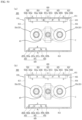


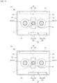


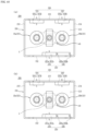

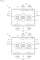





Classifications
-
- H—ELECTRICITY
- H01—ELECTRIC ELEMENTS
- H01H—ELECTRIC SWITCHES; RELAYS; SELECTORS; EMERGENCY PROTECTIVE DEVICES
- H01H9/00—Details of switching devices, not covered by groups H01H1/00 - H01H7/00
- H01H9/30—Means for extinguishing or preventing arc between current-carrying parts
- H01H9/44—Means for extinguishing or preventing arc between current-carrying parts using blow-out magnet
- H01H9/443—Means for extinguishing or preventing arc between current-carrying parts using blow-out magnet using permanent magnets
-
- H—ELECTRICITY
- H01—ELECTRIC ELEMENTS
- H01H—ELECTRIC SWITCHES; RELAYS; SELECTORS; EMERGENCY PROTECTIVE DEVICES
- H01H50/00—Details of electromagnetic relays
- H01H50/16—Magnetic circuit arrangements
- H01H50/36—Stationary parts of magnetic circuit, e.g. yoke
- H01H50/42—Auxiliary magnetic circuits, e.g. for maintaining armature in, or returning armature to, position of rest, for damping or accelerating movement
-
- H—ELECTRICITY
- H01—ELECTRIC ELEMENTS
- H01H—ELECTRIC SWITCHES; RELAYS; SELECTORS; EMERGENCY PROTECTIVE DEVICES
- H01H50/00—Details of electromagnetic relays
- H01H50/16—Magnetic circuit arrangements
- H01H50/36—Stationary parts of magnetic circuit, e.g. yoke
- H01H50/38—Part of main magnetic circuit shaped to suppress arcing between the contacts of the relay
-
- H—ELECTRICITY
- H01—ELECTRIC ELEMENTS
- H01H—ELECTRIC SWITCHES; RELAYS; SELECTORS; EMERGENCY PROTECTIVE DEVICES
- H01H50/00—Details of electromagnetic relays
- H01H50/54—Contact arrangements
- H01H50/546—Contact arrangements for contactors having bridging contacts
-
- H—ELECTRICITY
- H01—ELECTRIC ELEMENTS
- H01H—ELECTRIC SWITCHES; RELAYS; SELECTORS; EMERGENCY PROTECTIVE DEVICES
- H01H51/00—Electromagnetic relays
- H01H51/29—Relays having armature, contacts, and operating coil within a sealed casing
Definitions
- the present invention relates to an arc path generation unit and a DC relay including the same, and more specifically to an arc path generation unit having a structure capable of effectively inducing a generated arc to the outside and a DC relay including the same.
- a direct current (DC) relay is a device that transmits a mechanical drive or current signal by using the principle of an electromagnet.
- the direct current relay is also called a magnetic switch and is generally classified as an electrical circuit switch.
- the direct current relay includes a fixed contact and a movable contact.
- the fixed contact is electrically connected to an external power source and load.
- the fixed contact and the movable contact may be in contact with each other or may be spaced apart from each other.
- the conduction through the DC relay is allowed or blocked.
- the movement is achieved by a drive unit that applies a drive force to the movable contact.
- an arc is generated between the fixed contact and the movable contact.
- An arc is a flow of high-pressure, high-temperature current. Accordingly, the generated arc must be rapidly discharged from the DC relay through a preset path.
- the discharge path of arc is formed by a magnet provided in the DC relay.
- the magnet forms a magnetic field in the space where the fixed contact and the movable contact are in contact.
- the discharge path of arc may be formed by the formed magnetic field and the electromagnetic force generated by the flow of current.
- FIG. 1 a space in which a fixed contact 1100 and a movable contact 1200 provided in a DC relay 1000 according to prior art are in contact with each other is illustrated. As described above, a permanent magnet 1300 is provided in the space.
- the permanent magnet 1300 includes a first permanent magnet 1310 positioned on the upper side and a second permanent magnet 1320 positioned on the lower side.
- a plurality of first permanent magnets 1310 are provided, and the polarities of each surface facing the second permanent magnet 1320 are magnetized with different polarities.
- the lower side of the first permanent magnet 1310 located on the left side of FIG. 1 is magnetized to the N pole, and the second permanent magnet 1310 located on the right side of FIG. 1 is magnetized to the S pole.
- a plurality of second permanent magnets 1320 are also provided, and the polarities of each surface facing the first permanent magnet 1310 are magnetized with different polarities.
- the upper side of the second permanent magnet 1320 positioned on the left side of FIG. 1 is magnetized to the S pole, and the upper side of the second permanent magnet 1320 positioned on the right side of FIG. 1 is magnetized to the N pole.
- FIG. 1 illustrates a state in which current flows in through the fixed contact 1100 on the left side and flows out through the fixed contact 1100 on the right side.
- the electromagnetic force is formed like a hatched arrow.
- the electromagnetic force is formed toward the outside. Accordingly, the arc generated at the position may be discharged to the outside.
- the electromagnetic force is formed toward the inner side, that is, the central portion of the movable contact 1200. Accordingly, the arc generated at the corresponding position is not immediately discharged to the outside.
- FIG. 1 illustrates a state in which current flows in through the fixed contact 1100 on the right side and flows out through the fixed contact 1100 on the left side.
- the electromagnetic force is formed with a hatched arrow.
- the electromagnetic force is formed toward the outside. Accordingly, the arc generated at the position may be discharged to the outside.
- the electromagnetic force is formed toward the inside, that is, the central portion of the movable contact 1200. Accordingly, the arc generated at the position is not immediately discharged to the outside.
- various members for driving the movable contact 1200 in the vertical direction are provided.
- a shaft, a spring member inserted through the shaft and the like are provided at the position.
- the direction of the electromagnetic force formed inside the DC relay 1000 depends on the direction of the current flowing through the fixed contact 1200. That is, the position of the electromagnetic force formed in the inward direction among the electromagnetic forces generated at each fixed contact point 1100 is different depending on the direction of the current.
- the user must consider the direction of current whenever using a DC relay. This may cause inconvenience to the use of the DC relay.
- a situation in which the direction of the current applied to the DC relay is changed due to inexperienced operation or the like cannot be excluded.
- the members provided in the central portion of the DC relay may be damaged by the generated arc. Accordingly, the durability life of the DC relay is reduced, and there is a risk that safety accidents may occur.
- Korean Registered Patent No. 10-1696952 discloses a DC relay. Specifically, it discloses a DC relay having a structure capable of preventing the movement of a movable contact by using a plurality of permanent magnets.
- the DC relay having the above-described structure can prevent the movement of a movable contact by using a plurality of permanent magnets, but there is a limitation in that there is no consideration of a method for controlling the direction of the arc discharge path.
- Korean Registered Patent No. 10-1216824 discloses a DC relay. Specifically, it discloses a DC relay having a structure capable of preventing arbitrary separation between a movable contact and a fixed contact by using a damping magnet.
- the DC relay having the above-described structure proposes only a method for maintaining the contact state between the movable contact and the fixed contact. That is, there is a limitation in that it cannot propose a method for forming an arc discharge path generated when the movable contact and the fixed contact are spaced apart.
- An object of the present invention is to provide an arc path generation unit having a structure capable of solving the above-described problems, and a DC relay including the same.
- an object of the present invention is to provide an arc path generation unit having a structure capable of rapidly extinguishing and discharging an arc generated as current is cut off, and a DC relay including the same.
- an object of the present invention is to provide an arc path generation unit having a structure capable of strengthening the magnitude of the force for inducing the generated arc, and a DC relay including the same.
- an object of the present invention is to provide an arc path generation unit having a structure capable of preventing damage to components for energization by the generated arc, and a DC relay including the same.
- an object of the present invention is to provide an arc path generation unit having a structure in which arcs generated at a plurality of positions can proceed without meeting each other, and a DC relay including the same.
- an object of the present invention is to provide an arc path generation unit having a structure capable of achieving the above-described objects without excessive design changes, and a DC relay including the same.
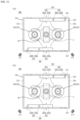
- the present invention provides an arc path generation unit, including a magnetic frame having a space part in which a fixed contact and a movable contact are accommodated; and a Halbach array which is positioned in the space part of the magnetic frame to form a magnetic field in the space part, and a magnet part which is provided separately from the Halbach array, wherein the space part has a length in one direction formed to be longer than a length in the other direction, wherein the magnetic frame includes a first surface and a second surface which extend in the one direction and are disposed to face each other to enclose a portion of the space part; and a third surface and a fourth surface which extend in the other direction, are continuous with the first surface and the second surface, respectively, and are disposed to face each other to enclose the remaining portion of the space part, wherein the Halbach array includes a plurality of blocks which are arranged side by side in the one direction and formed of a magnetic material, and is positioned adjacent to any one or more surfaces of the first surface and the
- the magnet part of the arc path generation unit may include a first magnet part and a second magnet part which are positioned adjacent to any one surface of the third surface and the fourth surface and arranged side by side with each other in the other direction; a third magnet part and a fourth magnet part which are positioned adjacent to the other one surface of the third surface and the fourth surface and arranged side by side with each other in the other direction; and a fifth magnet part which is positioned adjacent to the other one surface of the first surface and the second surface and arranged to face the Halbach array with the space part therebetween.
- each surface of the arc path generation unit on which any one block of a plurality of blocks and the fifth magnet part face each other is magnetized with the same polarity, and wherein each surface on which the first magnet part and the second magnet part face each other, and each surface on which the third magnet part and the fourth magnet part face each other are magnetized with a polarity different from the polarity.
- a plurality of blocks of the Halbach array of the arc path generation unit may include a first block which is positioned to be biased toward any one surface of the third surface and the fourth surface; a third block which is positioned to be biased toward the other one surface of the third surface and the fourth surface; and a second block which is positioned between the first block and the third block, wherein a surface of the surfaces of the first block facing the second block, a surface of the surfaces of the third block facing the second block and a surface of the surfaces of the second block facing the fifth magnet are magnetized with the same polarity as the polarity.
- a plurality of blocks of the Halbach array of the arc path generation unit may include a first block which is to be biased toward any one surface of the third surface and the fourth surface; a fifth block which is positioned to be biased toward the other one surface of the third surface and the fourth surface; and a second block, a third block and a fourth block which are positioned between the first block and the fifth block and sequentially arranged in a direction from the first block to the fifth block, wherein a surface of the surfaces of the second block facing the third block, a surface of the surfaces of the fourth block facing the third block and a surface of the surfaces of the third block facing the fifth magnet part are magnetized with the same polarity as the polarity.
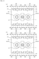
- the Halbach array of the arc path generation unit may include a first Halbach array which is positioned adjacent to any one surface of the first surface and the second surface; and a second Halbach array which is positioned adjacent to the other one surface of the first surface and the second surface, and disposed to face the first Halbach array with the space part therebetween, and wherein the magnet part includes a first magnet part and a second magnet part which are positioned adjacent to any one surface of the third surface and the fourth surface and arranged side by side with each other in the other direction; and a third magnet part and a fourth magnet part which are positioned adj acent to the other one surface of the third surface and the fourth surface and arranged side by side with each other in the other direction.
- each surface on which any one block of the plurality of blocks included in the first Halbach array and any one block of the plurality of blocks included in the second Halbach array face each other is magnetized with the same polarity, and wherein each surface on which the first magnet part and the second magnet part face each other, and each surface on which the third magnet part and the fourth magnet part face each other are magnetized with a polarity different from the polarity.
- first Halbach array and the second Halbach array of the arc path generation unit may respectively include a first block which is positioned to be biased toward any one surface of the third surface and the fourth surface; a fifth block which is positioned to be biased toward the other one surface of the third surface and the fourth surface; and a second block, a third block and a fourth block which are positioned between the first block and the fifth block and sequentially arranged in a direction from the first block to the fifth block, wherein in the first Halbach array, a surface of the surfaces of the second block facing the third block, a surface of the surfaces of the fourth block facing the third block and a surface of the surfaces of the third block facing the second Halbach array are magnetized with the same polarity as the polarity, and wherein in the second Halbach array, a surface of the surfaces of the second block facing the third block, a surface of the surfaces of the fourth block facing the third block and a surface of the surfaces of the third block facing the first Halbach array are magnetized with a polarity different from
- the first Halbach array and the second Halbach array of the arc path generation unit may respectively include a first block which is positioned to be biased toward any one surface of the third surface and the fourth surface; a third block which is positioned to be biased toward the other one surface of the third surface and the fourth surface; and a second block which is positioned between the first block and the third block, wherein in the first Halbach array, a surface of the surfaces of the first block facing the second block, a surface of the surfaces of the third block facing the second block and a surface of the surfaces of the second block facing the second Halbach array are magnetized with the same polarity as the polarity, and wherein in the second Halbach array, a surface of the surfaces of the first block facing the second block, a surface of the surfaces of the third block facing the second block and a surface of the surfaces of the second block facing the first Halbach array are magnetized with a polarity different from the polarity.
- the first Halbach array of the arc path generation unit may include a first block which is positioned to be biased toward any one surface of the third surface and the fourth surface; a third block which is positioned to be biased toward the other one surface of the third surface and the fourth surface; and a second block which is positioned between the first block and the third block, wherein the second Halbach array may include a first block which is positioned to be biased toward any one surface of the third surface and the fourth surface; a fifth block which is positioned to be biased toward the other one surface of the third surface and the fourth surface; and a second block, a third block and a fourth block which are positioned between the first block and the fifth block and sequentially arranged in a direction from the first block to the fifth block, wherein in the first Halbach array, a surface of the surfaces of the first block facing the second block, a surface of the surfaces of the third block facing the second block and a surface of the surfaces of the second block facing the second Halbach array are magnetized with the same polarity as the polar
- the Halbach array of the arc path generation unit may include a first Halbach array which is positioned adjacent to any one surface of the first surface and the second surface; and a second Halbach array which is positioned adjacent to the other one surface of the first surface and the second surface, and disposed to face the first Halbach array with the space part therebetween, and wherein the magnet part may include a first magnet part which is positioned adjacent to any one surface of the third surface and the fourth surface, and is positioned to be biased toward any one surface of the first surface and the second surface; and a second magnet part which is positioned adjacent to the other one surface of the third surface and the fourth surface, and is positioned to be biased toward the other one surface of the first surface and the second surface.
- each surface on which any one block of the plurality of blocks included in the first Halbach array and any one block of the plurality of blocks included in the second Halbach array face each other is magnetized with the same polarity, and wherein a surface of the first surface and the second surface among the surfaces of the first magnet part facing the other one surface, and a surface of the first surface and the second surface among the surfaces of the second magnet part facing the any one surface are magnetized with a polarity different from the polarity.
- the first Halbach array and the second Halbach array of the arc path generation unit may respectively include a first block which is positioned to be biased toward any one surface of the third surface and the fourth surface; a third block which is positioned to be biased toward the other one surface of the third surface and the fourth surface; and a second block which is positioned between the first block and the third block, wherein in the first Halbach array, a surface of the surfaces of the first block facing the second block, a surface of the surfaces of the third block facing the second block and a surface of the surfaces of the second block facing the second Halbach array are magnetized with the same polarity as the polarity, and wherein in the second Halbach array, a surface of the surfaces of the first block facing the second block, a surface of the surfaces of the third block facing the second block and a surface of the surfaces of the second block facing the first Halbach array are magnetized with a polarity different from the polarity.
- first Halbach array and the second Halbach array of the arc path generation unit may respectively include a first block which is positioned to be biased toward any one surface of the third surface and the fourth surface; a fifth block which is positioned to be biased toward the other one surface of the third surface and the fourth surface; and a second block, a third block and a fourth block which are positioned between the first block and the fifth block and sequentially arranged in a direction from the first block to the fifth block, wherein in the first Halbach array, a surface of the surfaces of the second block facing the third block, a surface of the surfaces of the fourth block facing the third block and a surface of the surfaces of the third block facing the second Halbach array are magnetized with the same polarity as the polarity, and wherein in the second Halbach array, a surface of the surfaces of the second block facing the third block, a surface of the surfaces of the fourth block facing the third block and a surface of the surfaces of the third block facing the first Halbach array are magnetized with a polarity different from
- the present invention provides a direct current relay, including a plurality of fixed contacts provided to be spaced apart from each other in one direction; a movable contact contacting or spaced apart from the fixed contact; a magnetic frame having a space part in which the fixed contact and the movable contact are accommodated; and a Halbach array which is positioned in the space part of the magnetic frame to form a magnetic field in the space part, and a magnet part which is provided separately from the Halbach array, wherein the space part has a length in one direction formed to be longer than a length in the other direction, wherein the magnetic frame may include a first surface and a second surface which extend in the one direction and are disposed to face each other to enclose a portion of the space part; and a third surface and a fourth surface which extend in the other direction, are continuous with the first surface and the second surface, respectively, and are disposed to face each other to enclose the remaining portion of the space part, wherein the Halbach array may include a plurality of blocks which are arranged side
- the magnet part of the direct current relay may include a first magnet part and a second magnet part which are positioned adjacent to any one surface of the third surface and the fourth surface and arranged side by side with each other in the other direction; a third magnet part and a fourth magnet part which are positioned adjacent to the other one surface of the third surface and the fourth surface and arranged side by side with each other in the other direction; and a fifth magnet part which is positioned adjacent to the other one surface of the first surface and the second surface and arranged to face the Halbach array with the space part therebetween, wherein each surface on which any one block of a plurality of blocks and the fifth magnet part face each other is magnetized with the same polarity, and wherein each surface on which the first magnet part and the second magnet part face each other, and each surface on which the third magnet part and the fourth magnet part face each other are magnetized with a polarity different from the polarity.
- the Halbach array of the direct current relay may include a first Halbach array which is positioned adjacent to any one surface of the first surface and the second surface; and a second Halbach array which is positioned adjacent to the other one surface of the first surface and the second surface, and disposed to face the first Halbach array with the space part therebetween
- the magnet part may include a first magnet part and a second magnet part which are positioned adjacent to any one surface of the third surface and the fourth surface and arranged side by side with each other in the other direction; and a third magnet part and a fourth magnet part which are positioned adj acent to the other one surface of the third surface and the fourth surface and arranged side by side with each other in the other direction, wherein each surface on which any one block of the plurality of blocks included in the first Halbach array and any one block of the plurality of blocks included in the second Halbach array face each other is magnetized with the same polarity, and wherein each surface on which the first magnet part and the second magnet part face each other, and each surface on which
- the Halbach array of the direct current relay may include a first Halbach array which is positioned adjacent to any one surface of the first surface and the second surface; and a second Halbach array which is positioned adjacent to the other one surface of the first surface and the second surface, and disposed to face the first Halbach array with the space part therebetween
- the magnet part may include a first magnet part and a second magnet part which are positioned adjacent to any one surface of the third surface and the fourth surface and arranged side by side with each other in the other direction; and a third magnet part and a fourth magnet part which are positioned adj acent to the other one surface of the third surface and the fourth surface and arranged side by side with each other in the other direction, wherein each surface on which any one block of the plurality of blocks included in the first Halbach array and any one block of the plurality of blocks included in the second Halbach array face each other is magnetized with the same polarity, and wherein a surface of the surfaces of the first magnet part facing the other one surface of the first surface and the second surface, and
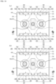
- the present invention provides an arc path generation unit, including a magnetic frame having a space part in which a plurality of fixed contacts and a plurality of movable contacts are accommodated; and a Halbach array which is positioned in the space part of the magnetic frame to form a magnetic field in the space part, wherein the space part has a length in one direction formed to be longer than a length in the other direction, wherein the magnetic frame may include a first surface and a second surface which extend in the one direction and are disposed to face each other to enclose a portion of the space part; and a third surface and a fourth surface which extend in the other direction, are continuous with the first surface and the second surface, respectively, and are disposed to face each other to enclose the remaining portion of the space part, wherein the Halbach array may include a first Halbach array including a plurality of blocks that are arranged side by side in the one direction and formed of a magnetic material, and which is arranged adjacent to any one surface of the first surface and the second surface; and a
- each surface on which the first Halbach array and the second Halbach array face each other is magnetized with the same polarity.
- the first Halbach array of the arc path generation unit may include a second block which is positioned to be biased toward any one surface of the third surface and the fourth surface; a third block which is positioned to be biased toward the other one surface of the third surface and the fourth surface; and a first block which is positioned between the second block and the third block, and wherein the second Halbach array may include a second block which is positioned to be biased toward the any one surface of the third surface and the fourth surface; a third block which is positioned to be biased toward the other one surface of the third surface and the fourth surface; and a first block which is positioned between the second block and the third block.
- each surface on which the first block of the first Halbach array and the first block of the second Halbach array face each other is magnetized with the same polarity.
- the first Halbach array of the arc path generation unit may include a second block which is positioned to be biased toward any one surface of the third surface and the fourth surface; a third block which is positioned to be biased toward the other one surface of the third surface and the fourth surface; a first block which is positioned between the second block and the third block; a fourth block which is positioned between the first block and the second block; and a fifth block which is positioned between the first block and the third block
- the second Halbach array may include a second block which is positioned to be biased toward the any one of the third surface and the fourth surface; a third block which is positioned to be biased toward the other one surface of the third surface and the fourth surface; a first block which is positioned between the second block and the third block; a fourth block which is positioned between the first block and the second block; and a fifth block which is positioned between the first block and the third block
- each surface on which the first block of the first Halbach array and the first block of the second Halbach array face each other is magnetized with the same polarity
- each surface on which the second block of the first Halbach array and the second block of the second Halbach array face each other is magnetized with a polarity different from the polarity
- each surface on which the third block of the first Halbach array and the third block of the second Halbach array face each other is magnetized with a polarity different from the polarity.
- the first Halbach array of the arc path generation unit may include a second block which is positioned to be biased toward any one surface of the third surface and the fourth surface; a third block which is positioned to be biased toward the other one surface of the third surface and the fourth surface; and a first block which is positioned between the second block and the third block
- the second Halbach array may include a second block which is positioned to be biased toward the any one surface of the third surface and the fourth surface; a third block which is positioned to be biased toward the other one surface of the third surface and the fourth surface; a first block which is positioned between the second block and the third block; a fourth block which is positioned between the first block and the second block; and a fifth block which is positioned between the first block and the third block, and wherein the first Halbach array is positioned to be biased toward any one surface of the third surface and the fourth surface.
- each surface on which the first block of the first Halbach array and the first block of the second Halbach array face each other is magnetized with the same polarity, and wherein each surface on which the second block of the second Halbach array faces the first Halbach array, and each surface on which the third block of the second Halbach array faces the first Halbach array are magnetized with a polarity different from the polarity.
- the present invention provides an arc path generation unit, including a magnetic frame having a space part in which a plurality of fixed contacts and a plurality of movable contacts are accommodated; and a Halbach array which is positioned in the space part of the magnetic frame to form a magnetic field in the space part, wherein the space part has a length in one direction formed to be longer than a length in the other direction, wherein the magnetic frame may include a first surface and a second surface which extend in the one direction and are disposed to face each other to enclose a portion of the space part; and a third surface and a fourth surface which extend in the other direction, are continuous with the first surface and the second surface, respectively, and are disposed to face each other to enclose the remaining portion of the space part, wherein the Halbach array may include a first Halbach array including a plurality of blocks that are arranged side by side in the one direction and formed of a magnetic material, and which is arranged adjacent to any one surface of the first surface and the second surface; and a
- each surface on which the first Halbach array and the second Halbach array face each other is magnetized with the same polarity.
- the first Halbach array of the arc path generation unit may include a first block which is arranged to overlap the second Halbach array along the other direction; and a second block which is positioned to be biased toward the other one surface of the third surface and the fourth surface, and wherein the second Halbach array may include a first block which is arranged to overlap the first Halbach array along the other direction; and a second block which is positioned to be biased toward the any one surface of the third surface and the fourth surface.
- each surface on which the first block of the first Halbach array and the first block of the second Halbach array face each other is magnetized with the same polarity.
- the first Halbach array of the arc path generation unit may include a second block which is positioned to be biased toward the any one surface of the third surface and the fourth surface; a third block which is positioned to be biased toward the other one surface of the third surface and the fourth surface; and a first block which is positioned between the second block and the third block
- the second Halbach array may include a second block which is positioned to be biased toward the other one surface of the third surface and the fourth surface; a third block which is positioned to be biased toward the any one surface of the third surface and the fourth surface; and a first block which is positioned between the second block and the third block, wherein the first Halbach array is arranged to overlap any one of the plurality of fixed contacts along the other direction, and wherein the second Halbach array is arranged to overlap the other one of the plurality of fixed contacts along the other direction.
- each surface of the surfaces of the first block of the first Halbach array facing the space part and each surface of the surfaces of the first block of the second Halbach array facing the space part are magnetized with the same polarity.
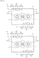
- the present invention provides an arc path generation unit, including a magnetic frame having a space part in which a plurality of fixed contacts and a plurality of movable contacts are accommodated; and a Halbach array which is positioned in the space part of the magnetic frame to form a magnetic field in the space part, wherein the space part has a length in one direction formed to be longer than a length in the other direction, wherein the magnetic frame may include a first surface and a second surface which extend in the one direction and are disposed to face each other to enclose a portion of the space part; and a third surface and a fourth surface which extend in the other direction, are continuous with the first surface and the second surface, respectively, and are disposed to face each other to enclose the remaining portion of the space part, wherein the Halbach array may include a plurality of blocks that are arranged side by side in the one direction and formed of a magnetic material, wherein a plurality of Halbach arrays are provided, and at least one of the plurality of Halbach arrays is
- each surface on which the at least one Halbach array disposed adjacent to the any one surface of the first surface and the second surface, and the at least two Halbach arrays disposed adjacent to the other one surface of the first surface and the second surface face each other are magnetized with the same polarity.
- the plurality of Halbach arrays of the arc path generation unit may include a first Halbach array which is positioned adjacent to the any one surface of the first surface and the second surface, and is positioned to be biased toward any one surface of the third surface and the fourth surface; a second Halbach array which is positioned adjacent to the any one surface of the first surface and the second surface, and is positioned to be biased toward the other one surface of the third surface and the fourth surface; a third Halbach array which is positioned adjacent to the other one surface of the first surface and the second surface, and is positioned to be biased toward the any one surface of the third surface and the fourth surface; and a fourth Halbach array which is positioned adjacent to the other one surface of the first surface and the second surface, and is positioned to be biased toward the other one surface of the third surface and the fourth surface.
- first Halbach array, the second Halbach array, the third Halbach array and the fourth Halbach array of the arc path generation unit may respectively include a second block which is positioned to be biased toward any one surface of the third surface and the fourth surface; a third block which is positioned to be biased toward the other one surface of the third surface and the fourth surface; and a first block which is positioned between the second block and the third block.
- a surface of the surfaces of the first block of the first Halbach array facing the space part and a surface of the surfaces of the first block of the third Halbach array facing the space part are respectively magnetized with the same polarity
- a surface of the surfaces of the first block of the second Halbach array facing the space part and a surface of the surfaces of the first block of the fourth Halbach array facing the space part are respectively magnetized with the same polarity as the polarity.
- the plurality of Halbach arrays of the arc path generation unit may include a first Halbach array which is positioned adjacent to the any one surface of the first surface and the second surface, and is positioned to be biased toward any one surface of the third surface and the fourth surface; a second Halbach array which is positioned adjacent to the other one surface of the first surface and the second surface, and is positioned to be biased toward any one surface of the third surface and the fourth surface; and a third Halbach array which is positioned adjacent to the other one surface of the first surface and the second surface, and is positioned to be biased toward the other one surface of the third surface and the fourth surface, and wherein the first Halbach array is arranged to overlap any one of the second Halbach array and the third Halbach array along the other direction.
- first Halbach array, the second Halbach array and the third Halbach array of the arc path generation unit may respectively include a second block which is positioned to be biased toward any one surface of the third surface and the fourth surface; a third block which is positioned to be biased toward the other one surface of the third surface and the fourth surface; and a first block which is positioned between the second block and the third block.
- a surface of the surfaces of the first block of the first Halbach array facing the space part, a surface of the surfaces of the first block of the second Halbach array facing the space part and a surface of the surfaces of the first block of the third Halbach array facing the space part are respectively magnetized with the same polarity.
- the plurality of Halbach arrays of the arc path generation unit may include a first Halbach array which is positioned to be biased toward any one surface of the third surface and the fourth surface; a second Halbach array which is positioned adjacent to the other one surface of the first surface and the second surface, and is positioned to be biased toward any one surface of the third surface and the fourth surface; and a third Halbach array which is positioned adjacent to the other one surface of the first surface and the second surface, and is positioned to be biased toward the other one surface of the third surface and the fourth surface, and wherein the first Halbach array is arranged to overlap the second Halbach array and the third Halbach array along the other direction, respectively.
- first Halbach array, the second Halbach array and the third Halbach array of the arc path generation unit may respectively include a second block which is positioned to be biased toward any one surface of the third surface and the fourth surface; a third block which is positioned to be biased toward the other one surface of the third surface and the fourth surface; and a first block which is positioned between the second block and the third block.
- a surface of the surfaces of the first block of the first Halbach array facing the space part, a surface of the surfaces of the first block of the second Halbach array facing the space part and a surface of the surfaces of the first block of the third Halbach array facing the space part are respectively magnetized with the same polarity.
- the present invention provides a direct current relay, including a plurality of fixed contacts provided to be spaced apart from each other in one direction; a movable contact contacting or spaced apart from the fixed contact; a magnetic frame having a space part in which the fixed contact and the movable contact are accommodated; and a Halbach array which is positioned in the space part of the magnetic frame to form a magnetic field in the space part, wherein the space part has a length in one direction formed to be longer than a length in the other direction, wherein the magnetic frame may include a first surface and a second surface which extend in the one direction and are disposed to face each other to enclose a portion of the space part; and a third surface and a fourth surface which extend in the other direction, are continuous with the first surface and the second surface, respectively, and are disposed to face each other to enclose the remaining portion of the space part, wherein the Halbach array may include a first Halbach array including a plurality of blocks which are arranged side by side in the one direction and formed
- the present invention provides a direct current relay, including a plurality of fixed contacts provided to be spaced apart from each other in one direction; a movable contact contacting or spaced apart from the fixed contact; a magnetic frame having a space part in which the fixed contact and the movable contact are accommodated; and a Halbach array which is positioned in the space part of the magnetic frame to form a magnetic field in the space part, wherein the space part has a length in one direction formed to be longer than a length in the other direction, wherein the magnetic frame may include a first surface and a second surface which extend in the one direction and are disposed to face each other to enclose a portion of the space part; and a third surface and a fourth surface which extend in the other direction, are continuous with the first surface and the second surface, respectively, and are disposed to face each other to enclose the remaining portion of the space part, wherein the Halbach array may include a first Halbach array including a plurality of blocks which are arranged side by side in the one direction and formed
- the present invention provides a direct current relay, including a plurality of fixed contacts provided to be spaced apart from each other in one direction; a movable contact contacting or spaced apart from the fixed contact; a magnetic frame having a space part in which the fixed contact and the movable contact are accommodated; and a Halbach array which is positioned in the space part of the magnetic frame to form a magnetic field in the space part, wherein the space part has a length in one direction formed to be longer than a length in the other direction, wherein the magnetic frame may include a first surface and a second surface which extend in the one direction and are disposed to face each other to enclose a portion of the space part; and a third surface and a fourth surface which extend in the other direction, are continuous with the first surface and the second surface, respectively, and are disposed to face each other to enclose the remaining portion of the space part, wherein the Halbach array may include a plurality of blocks that are arranged side by side in the one direction and are formed of a magnetic material,
- the present invention provides an arc path generation unit, including a magnetic frame having a space part in which a plurality of fixed contacts and a plurality of movable contacts are accommodated; and a Halbach array which is positioned in the space part of the magnetic frame to form a magnetic field in the space part, wherein the space part has a length in one direction formed to be longer than a length in the other direction, wherein the magnetic frame may include a first surface and a second surface which extend in the one direction and are disposed to face each other to enclose a portion of the space part; and a third surface and a fourth surface which extend in the other direction, are continuous with the first surface and the second surface, respectively, and are disposed to face each other to enclose the remaining portion of the space part, and wherein the Halbach array may include a plurality of blocks which are arranged side by side in the one direction and formed of a magnetic material, and is arranged adjacent to any one surface of the first surface and the second surface, so as to be disposed to overlap any one
- the Halbach array of the arc path generation unit is positioned to be biased toward any one surface of the third surface and the fourth surface, is positioned to overlap any one of the plurality of fixed contacts in the other direction, and may include: a first block which is positioned to be biased toward the any one surface of the third surface and the fourth surface; and a second block which is positioned to be biased toward the other one surface of the third surface and the fourth surface.
- the Halbach array of the arc path generation unit may include a first Halbach array which is biased toward any one surface of the third surface and the fourth surface; and a second Halbach array which is biased toward the other one surface of the third surface and the fourth surface.
- a surface of the surfaces of the first Halbach array facing the space part and a surface of the surfaces of the second Halbach array facing the space part are magnetized with the same polarity.
- first Halbach array and the second Halbach array of the arc path generation unit may respectively include a second block which is positioned to be biased toward the any one surface of the third surface and the fourth surface; a third block which is positioned to be biased toward the other one surface of the third surface and the fourth surface; and a first block which is positioned between the second block and the third block.
- a surface of the surfaces of the first block of the first Halbach array facing the space part and a surface of the surfaces of the first block of the second Halbach array facing the space part are magnetized with the same polarity.
- the Halbach array of the arc path generation unit may include a second block which is positioned to be biased toward any one surface of the third surface and the fourth surface; a third block which is positioned to be biased toward the other one surface of the third surface and the fourth surface; a first block which is positioned between the second block and the third block; a fourth block which is positioned between the first block and the second block; and a fifth block which is positioned between the first block and the third block.
- a surface of the surfaces of the second block facing the space part and a surface of the surfaces of the third block facing the space part are magnetized with the same polarity, and wherein a surface of the surfaces of the first block facing the space part is magnetized with a polarity different from the polarity.
- the present invention provides an arc path generation unit, including a magnetic frame having a space part in which a plurality of fixed contacts and a plurality of movable contacts are accommodated; and a Halbach array which is positioned in the space part of the magnetic frame to form a magnetic field in the space part, and a magnet part which is provided separately from the Halbach array, wherein the space part has a length in one direction formed to be longer than a length in the other direction, wherein the magnetic frame may include a first surface and a second surface which extend in the one direction and are disposed to face each other to enclose a portion of the space part; and a third surface and a fourth surface which extend in the other direction, are continuous with the first surface and the second surface, respectively, and are disposed to face each other to enclose the remaining portion of the space part, wherein the Halbach array may include a plurality of blocks which are arranged side by side in the one direction and formed of a magnetic material, and is arranged adjacent to any one surface of the first surface and
- the Halbach array of the arc path generation unit is positioned to be biased toward any one surface of the third surface and the fourth surface, and is arranged to overlap any one of the plurality of fixed contacts in the other direction.
- each surface on which the magnet part and the Halbach array face each other is magnetized with the same polarity.
- the Halbach array of the arc path generation unit may include a first block which is positioned to be biased toward the other one surface of the third surface and the fourth surface; and a second block which is positioned to be biased toward the any one surface of the third surface and the fourth surface.
- a surface of the surfaces of the first block of the Halbach array facing the magnet part and a surface of the surfaces of the magnet part facing the Halbach array are magnetized with the same polarity.
- the Halbach array of the arc path generation unit may include a first Halbach array which is positioned to be biased toward any one surface of the third surface and the fourth surface, and is arranged to overlap any one of the plurality of fixed contacts in the other direction; and a second Halbach array which is positioned to be biased toward the other one surface of the third surface and the fourth surface, and is arranged to overlap the other one of the plurality of fixed contacts in the other direction.
- each surface on which the magnet part and the first Halbach array face each other and each surface on which the magnet part and the second Halbach array face each other are magnetized with the same polarity.
- first Halbach array and the second Halbach array of the arc path generation unit may respectively include a second block which is positioned to be biased toward the any one surface of the third surface and the fourth surface; a third block which is positioned to be biased toward the other one surface of the third surface and the fourth surface; and a first block which is positioned between the second block and the third block.
- a surface of the surfaces of the first block of the first Halbach array facing the magnet part, a surface of the surfaces of the first block of the second Halbach array facing the magnet part and a surface of the surfaces of the magnet part facing the space part are magnetized with the same polarity.
- the Halbach array of the arc path generation unit may include a second block which is positioned to be biased toward any one surface of the third surface and the fourth surface; a third block which is positioned to be biased toward the other one surface of the third surface and the fourth surface; a first block which is positioned between the second block and the third block; a fourth block which is positioned between the first block and the second block; and a fifth block which is positioned between the first block and the third block.
- a surface of the surfaces of the second block facing the magnet part and a surface of the surfaces of the third block facing the magnet part are magnetized with the same polarity, and wherein each surface on which the first block and the magnet part face each other is magnetized with a polarity different from the polarity.
- the present invention provides an arc path generation unit, including a magnetic frame having a space part in which a plurality of fixed contacts and a plurality of movable contacts are accommodated; and a Halbach array which is positioned in the space part of the magnetic frame to form a magnetic field in the space part, and a magnet part which is provided separately from the Halbach array, wherein the space part has a length in one direction formed to be longer than a length in the other direction, wherein the magnetic frame may include a first surface and a second surface which extend in the one direction and are disposed to face each other to enclose a portion of the space part; and a third surface and a fourth surface which extend in the other direction, are continuous with the first surface and the second surface, respectively, and are disposed to face each other to enclose the remaining portion of the space part, wherein the Halbach array may include a plurality of blocks which are arranged side by side in the one direction and formed of a magnetic material, and is arranged adjacent to any one surface of the first surface and
- the magnet part of the arc path generation unit may include a first magnet part which is positioned to be biased toward any one surface of the third surface and the fourth surface; and a second magnet part which is positioned to be biased toward the other one surface of the third surface and the fourth surface, and wherein the Halbach array is positioned to be biased toward the any one surface of the third surface and the fourth surface, so as to be arranged to overlap any one of the first magnet part and the second magnet part in the other direction.
- each surface on which the first magnet part and the Halbach array face each other, and each surface on which the second magnet part and the Halbach array face each other are magnetized with the same polarity.
- the Halbach array of the arc path generation unit may include a first block which is positioned to be biased toward the other one surface of the third surface and the fourth surface; and a second block which is positioned to be biased toward the any one surface of the third surface and the fourth surface, and is disposed to face any one of the first magnet part and the second magnet part.
- a surface of the surfaces of the first block of the Halbach array facing the first magnet part or the second magnet part, a surface of the surfaces of the first magnet part facing the Halbach array and a surface of the surfaces of the second magnet part facing the Halbach array are magnetized with the same polarity.
- the Halbach array of the arc path generation unit may include a first Halbach array which is positioned to be biased toward any one surface of the third surface and the fourth surface; and a second Halbach array which is positioned to be biased toward the other one surface of the third surface and the fourth surface, wherein the magnet part extends beyond a distance in which the plurality of fixed contacts are spaced apart from each other.
- each surface on which the first Halbach array and the magnet part of the arc path generation unit face each other, and each surface on which the second Halbach array and the magnet part face each other are magnetized with the same polarity.
- first Halbach array and the second Halbach array of the arc path generation unit may respectively include a second block which is positioned to be biased toward any one surface of the third surface and the fourth surface; a third block which is positioned to be biased toward the other one surface of the third surface and the fourth surface; and a first block which is positioned between the second block and the third block.
- a surface of the surfaces of the first block of the first Halbach array facing the magnet part, a surface of the surfaces of the first block of the second Halbach array facing the magnet part and a surface of the surfaces of the magnet part facing the first Halbach array or the second Halbach array are magnetized with the same polarity.
- the Halbach array of the arc path generation unit may include a second block which is positioned to be biased toward any one surface of the third surface and the fourth surface; a third block which is positioned to be biased toward the other one surface of the third surface and the fourth surface; a first block which is positioned between the second block and the third block; a fourth block which is positioned between the first block and the second block; and a fifth block which is positioned between the first block and the third block.
- a surface of the surfaces of the second block of the arc path generation unit facing the magnet part and a surface of the surfaces of the third block facing the magnet part are magnetized with the same polarity, and wherein each surface on which the first block and the magnet part face each other is magnetized with a polarity different from the polarity.
- the present invention provides a direct current relay, including a plurality of fixed contacts provided to be spaced apart from each other in one direction; a movable contact contacting or spaced apart from the fixed contact; a magnetic frame having a space part in which the fixed contact and the movable contact are accommodated; and a Halbach array which is positioned in the space part of the magnetic frame to form a magnetic field in the space part, wherein the space part has a length in one direction formed to be longer than a length in the other direction, wherein the magnetic frame may include a first surface and a second surface which extend in the one direction and are disposed to face each other to enclose a portion of the space part; and a third surface and a fourth surface which extend in the other direction, are continuous with the first surface and the second surface, respectively, and are disposed to face each other to enclose the remaining portion of the space part, and wherein the Halbach array may include a plurality of blocks that are arranged side by side in the one direction and are formed of a magnetic material
- the present invention provides a direct current relay, including a plurality of fixed contacts provided to be spaced apart from each other in one direction; a movable contact contacting or spaced apart from the fixed contact; a magnetic frame having a space part in which the fixed contact and the movable contact are accommodated; and a Halbach array which is positioned in the space part of the magnetic frame to form a magnetic field in the space part, and a magnet part which is provided separately from the Halbach array, wherein the space part has a length in one direction formed to be longer than a length in the other direction, wherein the magnetic frame may include a first surface and a second surface which extend in the one direction and are disposed to face each other to enclose a portion of the space part; and a third surface and a fourth surface which extend in the other direction, are continuous with the first surface and the second surface, respectively, and are disposed to face each other to enclose the remaining portion of the space part, wherein the Halbach array may include a plurality of blocks that are arranged side
- the present invention provides a direct current relay, including a plurality of fixed contacts provided to be spaced apart from each other in one direction; a movable contact contacting or spaced apart from the fixed contact; a magnetic frame having a space part in which the fixed contact and the movable contact are accommodated; and a Halbach array which is positioned in the space part of the magnetic frame to form a magnetic field in the space part, and a magnet part which is provided separately from the Halbach array, wherein the space part has a length in one direction formed to be longer than a length in the other direction, wherein the magnetic frame may include a first surface and a second surface which extend in the one direction and are disposed to face each other to enclose a portion of the space part; and a third surface and a fourth surface which extend in the other direction, are continuous with the first surface and the second surface, respectively, and are disposed to face each other to enclose the remaining portion of the space part, wherein the Halbach array may include a plurality of blocks that are arranged side
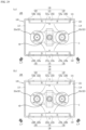
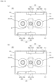
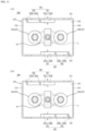
- the arc path generation unit includes a Halbach array and a magnet part.
- the Halbach array and the magnet part form a magnetic field inside the arc path generation unit, respectively.
- the formed magnetic field forms an electromagnetic force together with the current passed through the fixed contact and the movable contact which are accommodated in the arc path generation unit.
- the generated arc is formed in a direction away from each fixed contact.
- the arc generated by the fixed contact and the movable contact being spaced apart may be induced by the electromagnetic force.
- the generated arc can be quickly extinguished and discharged to the outside of the arc path generation unit and the DC relay.
- the arc path generation unit includes a Halbach array.
- the Halbach array includes a plurality of magnetic materials that are arranged side by side in one direction. The plurality of magnetic materials may further enhance the strength of the magnetic field on either side of both sides of the one direction and the other direction.
- the one side that is, the direction in which the strength of the magnetic field is strengthened, is disposed toward the space part of the arc path generation unit. That is, by the Halbach array, the strength of the magnetic field formed inside the space may be strengthened.
- the strength of the electromagnetic force that depends on the strength of the magnetic field may also be strengthened.
- the intensity of the electromagnetic force that induces the generated arc is strengthened, and thus, the generated arc can be effectively extinguished and discharged.
- the direction of the electromagnetic force formed by the magnetic field formed by the Halbach array and the magnet part and the current passed through the fixed contact and the movable contact is formed in a direction away from the center.
- the generated arc can be extinguished and moved quickly in a direction away from the center.
- a plurality of fixed contacts may be provided.
- the Halbach array or magnet part provided in the arc path generation unit forms magnetic fields in different directions in the vicinity of each fixed contact. Accordingly, the paths of arcs generated in the vicinity of each fixed contact proceed in different directions.
- the arc path generation unit includes a Halbach array and a magnet part provided in the space part.
- the Halbach array and the magnet part are located inwardly on each surface of the magnetic frame surrounding the space part. That is, separate design changes for disposing the Halbach array and the magnet part outside the space part are not required.
- the arc path generation unit according to various exemplary embodiments of the present invention may be provided in the DC relay without excessive design changes. Accordingly, the time and cost for applying the arc path generation unit according to various exemplary embodiments of the present invention may be reduced.
- magnetize used in the following description refers to a phenomenon in which an object becomes magnetic in a magnetic field.
- polarity used in the following description refers to different properties that the anode and cathode of an electrode have.
- the polarity may be classified into the N pole or the S pole.
- electrical current used in the following description refers to a state in which two or more members are electrically connected.
- arc path means a path through which the generated arc is moved or extinguished.
- ⁇ illustrated in the following drawings means a direction in which the current flows from a movable contact 43 toward a fixed contact 22 ( i.e., an upward direction), that is, the flow in a direction coming out of the ground.
- ⁇ illustrated in the following drawings means a direction in which the current flows from a fixed contact 22 toward a movable contact 43 ( i.e., downward direction), that is, a direction that penetrates the ground.
- Hybach Array used in the following description refers to an aggregate composed of a plurality of magnetic materials arranged side by side and configured in a column or a row.
- a plurality of magnetic materials constituting the Halbach array may be arranged according to a predetermined rule.
- the plurality of magnetic materials may form a magnetic field on their own or with each other.
- the Halbach array contains two relatively long surfaces and the other two relatively short surfaces.
- the magnetic field formed by the magnetic materials constituting the Halbach array may be formed with a stronger intensity on the outside of any one of the two long surfaces.
- magnet part used in the following description means an object of any shape that is formed of a magnetic material and may form a magnetic field.
- the magnet part may be provided with a permanent magnet or an electromagnet. It will be understood that the magnet part is a magnetic material which is different from the magnetic materials forming the Halbach array, that is, a magnetic material which is provided separately from the Halbach array.
- the magnet part may form a magnetic field by itself or in conjunction with another magnetic material.
- the magnet part may extend in one direction.
- the magnet part may be magnetized to have different polarities at both ends in the one direction ( i.e., it has different polarities in the longitudinal direction).
- the magnet part may be magnetized to have different polarities on both side surfaces of the one direction and the other direction ( i.e., it has different polarities in the width direction).
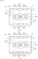
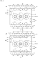
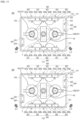
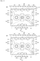
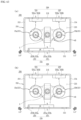
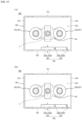
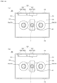
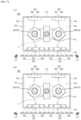
- the magnetic field formed by the arc path generation units 100, 200, 300, 400, 500, 600, 700, 800, 900 according to an exemplary embodiment of the present invention is illustrated by a dashed-dotted line in each drawing.
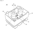
- the DC relay 1 includes a frame part 10, an opening/closing part 20, a core part 30 and a movable contact part 40.
- the DC relay 1 includes arc path generation units 100, 200, 300, 400, 500, 600, 700, 800, 900.
- the arc path generation units 100, 200, 300, 400, 500, 600, 700, 800, 900 may form a discharge path of the generated arc.
- the arc path generation units 100, 200, 300, 400, 500, 600, 700, 800, 900 are described on the assumption that these are provided in a direct current relay 1.
- the arc path generation units 100, 200, 300, 400, 500, 600, 700, 800, 900 may be applied to the type of devices that are capable of being energized and de-energized with the outside by the contact and separation of a fixed contact and a movable contact such as magnetic contacts and magnetic switches.
- the frame part 10 forms the outside of the DC relay 1.
- a predetermined space is formed inside the frame part 10.
- Various devices that perform a function for the DC relay 1 to apply or block an externally transmitted current may be accommodated in the space.
- the frame part 10 functions as a type of housing.
- the frame part 10 may be formed of an insulating material such as synthetic resin or the like. This is to prevent arbitrarily energizing the inside and outside of the frame part 10.
- the frame part 10 includes an upper frame 11, a lower frame 12, an insulating plate 13 and a support plate 14.
- the upper frame 11 forms the upper side of the frame part 10. A predetermined space is formed inside the upper frame 11.
- the opening/closing part 20 and the movable contact part 40 may be accommodated in the inner space of the upper frame 11.
- the arc path generation units 100, 200, 300, 400, 500, 600, 700 may be accommodated in the inner space of the upper frame 11.
- the upper frame 11 may be coupled to the lower frame 12.
- An insulating plate 13 and a support plate 14 may be provided in a space between the upper frame 11 and the lower frame 12.
- the fixed contact 22 of the opening/closing part 20 is positioned on the upper side in the illustrated exemplary embodiment. A portion of the fixed contact 22 is exposed on the upper side of the upper frame 11, and it may be connected to an external power source or a load to be energized.
- a through-hole through which the fixing contact 22 is coupled may be formed on the upper side of the upper frame 11.
- the lower frame 12 forms the lower side of the frame part 10.
- a predetermined space is formed inside the lower frame 12.
- the core part 30 may be accommodated in the inner space of the lower frame 12.
- the lower frame 12 may be coupled to the upper frame 11.
- An insulating plate 13 and a support plate 14 may be provided in a space between the lower frame 12 and the upper frame 11.
- the insulating plate 13 and the supporting plate 14 electrically and physically separate the inner space of the upper frame 11 and the inner space of the lower frame 12.
- the insulating plate 13 is positioned between the upper frame 11 and the lower frame 12.
- the insulating plate 13 electrically separates the upper frame 11 and the lower frame 12 from each other.
- the insulating plate 13 may be formed of an insulating material such as synthetic resin or the like.
- the insulating plate By the insulating plate, it is possible to prevent any electrical conduction between the opening/closing part 20, the movable contact part 40 and the arc path generation units 100, 200, 300, 400, 500, 600, 700, 800, 900 accommodated inside the upper frame 11 by the insulating plate 1, with the core part 30 accommodated inside the lower frame 12.
- a through-hole (not illustrated) is formed in the center of the insulating plate 13.
- the shaft 44 of the movable contact part 40 is coupled through the through-hole (not illustrated) to be movable in the vertical direction.
- a support plate 14 is positioned on the lower side of the insulating plate 13.
- the insulating plate 13 may be supported by the support plate 14.
- the support plate 14 is positioned between the upper frame 11 and the lower frame 12.
- the support plate 14 physically separates the upper frame 11 and the lower frame 12 from each other. In addition, the support plate 14 supports the insulating plate 13.
- the support plate 14 may be formed of a magnetic material. Accordingly, the support plate 14 may form a magnetic circuit together with the yoke 33 of the core part 30. By the magnetic path, a driving force for moving the movable core 32 of the core part 30 toward the fixed core 31 may be formed.
- a through-hole (not illustrated) is formed in the center of the support plate 14.
- a shaft 44 is coupled through the through-hole (not illustrated) to be movable in the vertical direction.
- the shaft 44 and the movable contact 43 connected to the shaft 44 may also be moved together in the same direction.
- the opening/closing unit 20 permits or blocks the flow of current according to the operation of the core part 30. Specifically, the opening/closing unit 20 may allow or block the flow of current by contacting or separating the fixed contact 22 and the movable contact 43 from each other.
- the opening/closing part 20 is accommodated in the inner space of the upper frame 11.
- the opening/closing part 20 may be electrically and physically spaced apart from the core part 30 by the insulating plate 13 and the supporting plate 14.
- the opening/closing part 20 includes an arc chamber 21, a fixed contact 22 and a sealing member 23.
- the arc path generation units 100, 200, 300, 400, 500, 600, 700, 800, 900 may be provided outside the arc chamber 21.
- the arc path generation units 100, 200, 300, 400, 500, 600, 700, 800, 900 may form a magnetic field for forming the path (A.P) of an arc generated inside the arc chamber 21.
- A.P path
- the arc chamber 21 extinguishes the arc generated by the fixed contact 22 and the movable contact 43 being spaced apart from each other in the inner space. Accordingly, the arc chamber 21 may be referred to as an "arc extinguishing unit.”
- the arc chamber 21 hermetically accommodates the fixed contact 22 and the movable contact 43. That is, the fixed contact 22 and the movable contact 43 are accommodated inside the arc chamber 21. Accordingly, the arc generated by the fixed contact 22 and the movable contact 43 being spaced apart does not flow out arbitrarily to the outside.
- the arc chamber 21 may be filled with an extinguishing gas.
- the extinguishing gas allows the generated arc to be extinguished and discharged to the outside of the DC relay 1 through a preset path.
- a communication hole (not illustrated) may be formed through the wall surrounding the inner space of the arc chamber 21.
- the arc chamber 21 may be formed of an insulating material.
- the arc chamber 21 may be formed of a material having high pressure resistance and high heat resistance. This is because the generated arc is a flow of high-temperature and high-pressure electrons.
- the arc chamber 21 may be formed of a ceramic material.
- a plurality of through-holes may be formed on the upper side of the arc chamber 21.
- a fixed contact 22 is through-coupled to each of the through-holes.
- the fixed contact 22 is provided in two, including a first fixed contact 22a and a second fixed contact 22b. Accordingly, two through-holes formed on the upper side of the arc chamber 21 may also be formed.
- the through-hole When the fixed contact 22 is through-coupled to the through-hole, the through-hole is sealed. That is, the fixed contact 22 is hermetically coupled to the through-hole. Accordingly, the generated arc is not discharged to the outside through the through-hole.
- the lower side of the arc chamber 21 may be open.
- the insulating plate 13 and the sealing member 23 are in contact with the lower side of the arc chamber 21. That is, the lower side of the arc chamber 21 is sealed by the insulating plate 13 and the sealing member 23.
- the arc chamber 21 may be electrically and physically spaced apart from the outer space of the upper frame 11.
- the arc extinguished in the arc chamber 21 is discharged to the outside of the DC relay 1 through a preset path.
- the extinguished arc may be discharged to the outside of the arc chamber 21 through the communication hole (not illustrated).
- the fixed contact 22 is in contact with or spaced apart from the movable contact 43 to apply or cut off electric conduction inside and outside the DC relay 1.
- the inside and the outside of the DC relay 1 may be energized.
- the fixed contact 22 is spaced apart from the movable contact 43, the electric current inside and outside the DC relay 1 is cut off.
- the fixed contact 22 is not moved. That is, the fixed contact 22 is fixedly coupled to the upper frame 11 and the arc chamber 21. Accordingly, contact and separation of the fixed contact 22 and the movable contact 43 are achieved by the movement of the movable contact 43.
- a power source or a load is connected to the one end to be energized, respectively.
- a plurality of fixed contacts 22 may be provided.
- the fixed contact 22 is provided in a total of two, including a first fixed contact 22a on the left side and a second fixed contact 22b on the right side.
- the first fixed contact 22a is positioned to be biased toward one side from the center in the longitudinal direction of the movable contact 43, which is to the left side in the illustrated exemplary embodiment.
- the second fixed contact 22b is positioned to be biased toward the other side from the center in the longitudinal direction of the movable contact 43, which is to the right in the illustrated exemplary embodiment.
- Power may be energably connected to any one of the first fixed contact 22a and the second fixed contact 22b.
- a load may be electrically connected to the other one of the first fixed contact 22a and the second fixed contact 22b.
- the DC relay 1 may form an arc path (A.P) regardless of the direction of the power or load connected to the fixed contact 22. This is accomplished by the arc path generation units 100, 200, 300, 400, 500, 600, 700, 800, 900, which will be described below in detail.
- the movable contact 43 When the movable contact 43 is moved in a direction toward the fixed contact 22, which is the upper side in the illustrated exemplary embodiment, the lower end is in contact with the movable contact 43. Accordingly, the outside and the inside of the DC relay 1 may be energized.
- the lower end of the fixed contact 22 is positioned inside the arc chamber 21.
- the movable contact 43 When the control power is cut off, the movable contact 43 is spaced apart from the fixed contact 22 by the elastic force of a return spring 36.
- an arc is generated between the fixed contact 22 and the movable contact 43.
- the generated arc may be extinguished by the extinguishing gas inside the arc chamber 21, and discharged to the outside along the path formed by the arc path generation units 100, 200, 300, 400, 500, 600, 700, 800, 900.
- the sealing member 23 blocks any communication between the arc chamber 21 and the space inside the upper frame 11.
- the sealing member 23 seals the lower side of the arc chamber 21 together with the insulating plate 13 and the support plate 14.
- the upper side of the sealing member 23 is coupled to the lower side of the arc chamber 21.
- the radially inner side of the sealing member 23 is coupled to the outer periphery of the insulating plate 13, and the lower side of the sealing member 23 is coupled to the support plate 14.
- the arc generated in the arc chamber 21 and the arc extinguished by the extinguishing gas do not arbitrarily flow into the inner space of the upper frame 11.
- sealing member 23 may be configured to block any communication between the inner space of the cylinder 37 and the inner space of the frame part 10.
- the core part 30 moves the movable contact part 40 upward according to the application of control power. In addition, when the application of control power is released, the core part 30 moves the movable contact part 40 downward again.
- the core part 30 may be connected to an external control power supply (not illustrated) so as to be energized, and may receive a control power supply.
- the core part 30 is positioned on the lower side of the opening/closing part 20. In addition, the core part 30 is accommodated inside the lower frame 12.
- the core part 30 and the opening/closing part 20 may be electrically and physically spaced apart from each other by the insulating plate 13 and the support plate 14.
- a movable contact part 40 is positioned between the core part 30 and the opening/closing part 20.
- the movable contact part 40 may be moved by the driving force applied by the core part 30. Accordingly, the movable contact 43 and the fixed contact 22 may be in contact such that the DC relay 1 may be energized.
- the core part 30 includes a fixed core 31, a movable core 32, a yoke 33, a bobbin 34, a coil 35, a return spring 36 and a cylinder 37.
- the fixed core 31 is magnetized by the magnetic field generated by the coil 35 to generate electromagnetic attraction.
- the movable core 32 is moved toward the fixed core 31 (an upward direction in FIG. 3 ).
- the fixed core 31 does not move. That is, the fixed core 31 is fixedly coupled to the support plate 14 and the cylinder 37.
- the fixed core 31 may be provided in any shape capable of generating electromagnetic force by being magnetized by a magnetic field.
- the fixed core 31 may be provided with a permanent magnet or an electromagnet.
- the fixed core 31 is partially accommodated in the upper space inside the cylinder 37.
- the outer periphery of the fixed core 31 is in contact with the inner periphery of the cylinder 37.
- the fixed core 31 is positioned between the support plate 14 and the movable core 32.
- a through-hole (not illustrated) is formed in the center of the fixed core 31.
- the shaft 44 is coupled through the through-hole (not illustrated) so as to be movable up and down.
- the fixed core 31 is positioned to be spaced apart from the movable core 32 by a predetermined distance. Accordingly, the distance at which the movable core 32 can be moved toward the fixed core 31 may be limited to the predetermined distance. Accordingly, the predetermined distance may be defined as "a moving distance of the movable core 32.”
- One end of the return spring 36 which is the upper end in the illustrated exemplary embodiment, is in contact with the lower side of the fixed core 31.
- the return spring 36 is compressed and a restoring force is stored.
- the movable core 32 may be returned to the lower side by the restoring force.
- the movable core 32 is moved toward the fixed core 31 by electromagnetic attraction generated by the fixed core 31 when control power is applied.
- the shaft 44 coupled to the movable core 32 is moved upward in the direction toward the fixed core 31, which is the upper side in the illustrated exemplary embodiment.
- the movable contact part 40 coupled to the shaft 44 is moved upward.
- the fixed contact 22 and the movable contact 43 are brought into contact such that the DC relay 1 may be energized with an external power source or load.
- the movable core 32 may be provided in any shape capable of receiving attractive force by electromagnetic force.
- the movable core 32 may be formed of a magnetic material, or may be provided with a permanent magnet or an electromagnet.
- the movable core 32 is accommodated in the cylinder 37.
- the movable core 32 may be moved in the longitudinal direction of the cylinder 37 inside the cylinder 37, which is the vertical direction in the illustrated exemplary embodiment.
- the movable core 32 may be moved in a direction toward the fixed core 31 and in a direction away from the fixed core 31.
- the movable core 32 is coupled to the shaft 44.
- the movable core 32 may move integrally with the shaft 44.
- the shaft 44 is also moved upward or downward. Accordingly, the movable contact 43 is also moved upward or downward.
- the movable core 32 is located on the lower side of the fixed core 31.
- the movable core 32 is spaced apart from the fixed core 31 by a predetermined distance.
- the predetermined distance is a distance at which the movable core 32 can be moved in the vertical direction.
- the movable core 32 is formed to extend in the longitudinal direction.
- a hollow part extending in the longitudinal direction is recessed by a predetermined distance inside the movable core 32.
- a return spring 36 and a lower side of the shaft 44 through-coupled to the return spring 36 are partially accommodated in the hollow part.
- a through-hole is formed through the lower side of the hollow part in the longitudinal direction.
- the hollow part and the through-hole communicate with each other.
- the lower end of the shaft 44 inserted into the hollow part may proceed toward the through-hole.
- a space part is recessed by a predetermined distance at the lower end of the movable core 32.
- the space part communicates with the through-hole.
- the lower head of the shaft 44 is positioned in the space.
- the yoke 33 forms a magnetic circuit as control power is applied.
- the magnetic path formed by the yoke 33 may be configured to adjust the direction of the magnetic field formed by the coil 35.
- the coil 35 may generate a magnetic field in a direction in which the movable core 32 moves toward the fixed core 31.
- the yoke 33 may be formed of a conductive material capable of conducting electricity.
- the yoke 33 is accommodated in the lower frame 12.
- the yoke 33 surrounds the coil 35.
- the coil 35 may be accommodated in the yoke 33 so as to be spaced apart from the inner circumferential surface of the yoke 33 by a predetermined distance.
- the bobbin 34 is accommodated inside the yoke 33. That is, from the outer periphery of the lower frame 12 to the radially inward direction, the yoke 33, the coil 35 and the bobbin 34 on which the coil 35 is wound are sequentially arranged.
- the upper side of the yoke 33 is in contact with the support plate 14.
- the outer periphery of the yoke 33 may be positioned to be in contact with the inner periphery of the lower frame 12 or to be spaced apart from the inner periphery of the lower frame 12 by a predetermined distance.
- a coil 35 is wound around the bobbin 34.
- the bobbin 34 is accommodated inside the yoke 33.
- the bobbin 34 may include flat upper and lower portions, and a cylindrical column extending in the longitudinal direction to connect the upper and lower portions. That is, the bobbin 34 has a bobbin shape.
- the upper portion of the bobbin 34 is in contact with the lower side of the support plate 14.
- a coil 35 is wound around the column part of the bobbin 34.
- the thickness around which the coil 35 is wound may be equal to or smaller than the diameters of the upper and lower portions of the bobbin 34.
- a hollow part extending in the longitudinal direction is formed through the column part of the bobbin 34.
- a cylinder 37 may be accommodated in the hollow part.
- the column part of the bobbin 34 may be disposed to have the same central axis as the fixed core 31, the movable core 32 and the shaft 44.
- the coil 35 generates a magnetic field by the applied control power.
- the fixed core 31 is magnetized by the magnetic field generated by the coil 35, and electromagnetic attraction may be applied to the movable core 32.
- the coil 35 is wound around a bobbin 34. Specifically, the coil 35 is wound on the column part of the bobbin 34, and is stacked radially outward of the column part. The coil 35 is accommodated inside the yoke 33.
- the coil 35 When the control power is applied, the coil 35 generates a magnetic field. In this case, the strength or direction of the magnetic field generated by the coil 35 may be controlled by the yoke 33.
- the fixed core 31 is magnetized by the magnetic field generated by the coil 35.
- the movable core 32 When the fixed core 31 is magnetized, the movable core 32 receives an electromagnetic force in a direction toward the fixed core 31, that is, an attractive force. Accordingly, the movable core 32 is moved in a direction toward the fixed core 31, which is upward in the illustrated exemplary embodiment.
- the return spring 36 provides a restoring force for the movable core 32 to return to its original position when the application of the control power is released after the movable core 32 is moved toward the fixed core 31.
- the return spring 36 is compressed as the movable core 32 is moved toward the fixed core 31 and stores a restoring force.
- the stored restoring force is smaller than the electromagnetic attraction force exerted on the movable core 32 by magnetizing the fixed core 31. This is to prevent the movable core 32 from being arbitrarily returned to its original position by the return spring 36 while the control power is applied.
- the movable core 32 When the application of the control power is released, the movable core 32 receives a restoring force by the return spring 36. Certainly, gravity due to the empty weight of the movable core 32 may also act on the movable core 32. Accordingly, the movable core 32 may be moved in a direction away from the fixed core 31 to return to the original position.
- the return spring 36 may be provided in any shape that is deformed in shape to store the restoring force, returns to its original shape, and transmits the restoring force to the outside.
- the return spring 36 may be provided as a coil spring.
- a shaft 44 is through-coupled to the return spring 36.
- the shaft 44 may be moved in the vertical direction regardless of the shape deformation of the return spring 36 in a state where the return spring 36 is coupled.
- the return spring 36 is accommodated in a hollow part which is formed to be recessed on the upper side of the movable core 32.
- one end of the return spring 36 facing the fixed core 31, which is the upper end in the illustrated exemplary embodiment, is accommodated in the hollow part which is formed to be recessed in the lower side of the fixed core 31.
- the cylinder 37 accommodates the fixed core 31, the movable core 32, the return spring 36 and the shaft 44.
- the movable core 32 and the shaft 44 may move upward and downward in the cylinder 37.
- the cylinder 37 is positioned in a hollow part formed in the column part of the bobbin 34.
- the upper end of the cylinder 37 is in contact with the lower surface of the support plate 14.
- the side surface of the cylinder 37 is in contact with the inner peripheral surface of the column part of the bobbin 34.
- the upper opening of the cylinder 37 may be sealed by the fixed core 31.
- the lower surface of the cylinder 37 may be in contact with the inner surface of the lower frame 12.
- the movable contact part 40 includes a movable contact 43 and a structure for moving the movable contact 43.
- the DC relay 1 may be energized with an external power source or load.
- the movable contact part 40 is accommodated in the inner space of the upper frame 11.
- the movable contact part 40 is accommodated in the arc chamber 21 to be movable up and down.
- a fixed contact 22 is positioned on the upper side of the movable contact part 40.
- the movable contact part 40 is accommodated in the arc chamber 21 so as to be movable in a direction toward the fixed contact 22 and a direction away from the fixed contact 22.
- the core part 30 is positioned on the lower side of the movable contact part 40.
- the movement of the movable contact part 40 may be achieved by movement of the movable core 32.
- the movable contact part 40 includes a housing 41, a cover 42, a movable contact 43, a shaft 44 and an elastic part 45.
- the housing 41 accommodates the movable contact 43 and the elastic part 45 for elastically supporting the movable contact 43.
- the housing 41 has one side and the other side opposite thereto open.
- the movable contact 43 may be inserted through the open portion.
- the unopened side surface of the housing 41 may be configured to surround the accommodated movable contact 43.
- a cover 42 is provided on the upper side of the housing 41.
- the cover 42 covers the upper surface of the movable contact 43 accommodated in the housing 41.
- the housing 41 and the cover 42 are preferably formed of an insulating material to prevent unintentional energization.
- the housing 41 and the cover 42 may be formed of synthetic resin or the like.
- the lower side of the housing 41 is connected to the shaft 44.
- the housing 41 and the movable contact 43 accommodated therein may also be moved upward or downward.
- the housing 41 and the cover 42 may be coupled by any member.
- the housing 41 and the cover 42 may be coupled by a fastening member (not illustrated) such as a bolt or a nut.
- the movable contact 43 is in contact with the fixed contact 22 according to the application of the control power such that the DC relay 1 is energized with an external power source and a load.
- the movable contact 43 is spaced apart from the fixed contact 22 when the application of the control power is released such that the DC relay 1 does not conduct electricity with an external power source and a load.
- the movable contact 43 is positioned adjacent to the fixed contact 22.
- the upper side of the movable contact 43 is partially covered by the cover 42.
- a portion of the upper surface of the movable contact 43 may be in contact with the lower surface of the cover 42.
- the lower side of the movable contact 43 is elastically supported by the elastic part 45.
- the elastic part 45 may elastically support the movable contact 43 in a compressed state by a predetermined distance.
- the movable contact 43 is formed to extend in the longitudinal direction, which is the left-right direction in the illustrated exemplary embodiment. That is, the length of the movable contact 43 is formed to be longer than the width. Accordingly, both ends in the longitudinal direction of the movable contact 43 accommodated in the housing 41 are exposed to the outside of the housing 41.
- Contact protrusions formed to protrude upward by a predetermined distance may be formed at both ends.
- a fixed contact 22 is in contact with the contact protrusion.
- the contact protrusion may be formed at a position corresponding to each of the fixed contacts 22a, 22b. Accordingly, the moving distance of the movable contact 43 may be reduced, and the contact reliability between the fixed contact 22 and the movable contact 43 may be improved.
- the width of the movable contact 43 may be the same as a distance at which each side surface of the housing 41 is spaced apart from each other. That is, when the movable contact 43 is accommodated in the housing 41, both side surfaces of the movable contact 43 in the width direction may contact the inner surface of each side surface of the housing 41.
- a state in which the movable contact 43 is accommodated in the housing 41 may be stably maintained.
- the shaft 44 transmits a driving force generated when the core part 30 is operated to the movable contact part 40.
- the shaft 44 is connected to the movable core 32 and the movable contact 43.
- the movable contact 43 may also be moved upward or downward by the shaft 44.
- the shaft 44 is formed to extend in the longitudinal direction, which is the vertical direction in the illustrated exemplary embodiment.
- the lower end of the shaft 44 is insertedly coupled to the movable core 32.
- the shaft 44 may be moved in the vertical direction together with the movable core 32.
- the body part of the shaft 44 is vertically movably coupled through the fixed core 31.
- a return spring 36 is coupled through the body part of the shaft 44.
- the upper end of the shaft 44 is coupled to the housing 41.
- the shaft 44 and the housing 41 may be moved together.
- the upper and lower ends of the shaft 44 may be formed to have a larger diameter than the body part of the shaft. Accordingly, the shaft 44 may be stably maintained in a coupled state with the housing 41 and the movable core 32.
- the elastic part 45 elastically supports the movable contact 43.
- the movable contact 43 comes into contact with the fixed contact 22, the movable contact 43 tends to be separated from the fixed contact 22 by electromagnetic repulsive force.
- the elastic part 45 elastically supports the movable contact 43, and prevents the movable contact 43 from being arbitrarily separated from the fixed contact 22.
- the elastic part 45 may be provided in any shape capable of storing a restoring force by deformation of a shape and providing the stored restoring force to another member.
- the elastic part 45 may be provided as a coil spring.
- One end of the elastic part 45 facing the movable contact 43 is in contact with the lower side of the movable contact 43.
- the other end opposite to the one end is in contact with the upper side of the housing 41.
- the elastic part 45 may be compressed by a predetermined distance to elastically support the movable contact 43 in a state where the restoring force is stored. Accordingly, even if an electromagnetic repulsive force is generated between the movable contact 43 and the fixed contact 22, the movable contact 43 is not arbitrarily moved.
- a protrusion (not illustrated) inserted into the elastic part 45 may be protruded under the movable contact 43.
- a protrusion (not illustrated) inserted into the elastic part 45 may protrude from the upper side of the housing 41.
- each of the arc path generation units 100, 200, 300, 400, 500, 600, 700 forms a magnetic field inside the arc chamber 21.
- An electromagnetic force is formed inside the arc chamber 21 by the current flowing through the DC relay 1 and the formed magnetic field.
- the arc generated as the fixed contact 22 and the movable contact 43 are spaced apart is moved to the outside of the arc chamber 21 by the formed electromagnetic force. Specifically, the generated arc is moved along the above direction of the formed electromagnetic force. Accordingly, it may be said that the arc path generation units 100, 200, 300, 400, 500, 600, 700 form the arc path (A.P), which is a path through which the generated arc flows.
- A.P arc path
- the arc path generation units 100, 200, 300, 400, 500, 600, 700 are positioned in a space formed inside the upper frame 11.
- the arc path generation units 100, 200, 300, 400, 500, 600, 700 are disposed to surround the arc chamber 21.
- the arc chamber 21 is located inside the arc path generation units 100, 200, 300, 400, 500, 600, 700.
- a fixed contact 22 and a movable contact 43 are positioned inside the arc path generation units 100, 200, 300, 400, 500, 600, 700.
- the arc generated by the fixed contact 22 and the movable contact 43 being spaced apart may be induced by an electromagnetic force formed by the arc path generation units 100, 200, 300, 400, 500, 600, 700.
- the arc path generation units 100, 200, 300, 400, 500, 600, 700 includes a Halbach array or a magnet part.
- the Halbach array or the magnet part forms a magnetic field inside the arc path generation units 100, 200, 300, 400, 500, 600, 700, in which the fixed contact 22 and the movable contact 43 are accommodated.
- the Halbach array or the magnet part may form a magnetic field by itself and between each other.
- the magnetic field formed by the Halbach array and the magnet part forms an electromagnetic force together with the current passed through the fixed contact 22 and the movable contact 43.
- the formed electromagnetic force induces an arc generated when the fixed contact 22 and the movable contact 43 are spaced apart.
- the arc path generation units 100, 200, 300, 400, 500, 600, 700 form an electromagnetic force in a direction away from the center (C) of the space parts 115, 215, 315, 415, 515, 615, 715. Accordingly, the arc path (A.P) is also formed in a direction away from the center (C) of the space.
- each component provided in the DC relay 1 is not damaged by the generated arc. Furthermore, the generated arc may be rapidly discharged to the outside of the arc chamber 21.
- each of the arc path generation units 100, 200, 300, 400, 500, 600, 700 and the path (A.P) of arc formed by each of the arc path generation units 100, 200, 300, 400, 500, 600, 700 will be described in detail.
- the arc path generation units 100, 200, 300, 400, 500, 600, 700 may have a Halbach array located on one or more sides of the front side and the rear side.
- the arc path generation units 100, 200, 300, 400, 500, 600, 700 may include a magnet part having a polarity in a longitudinal direction, which is positioned on at least one side of the left and right sides.
- the rear side may be defined as a direction which is adjacent to first surfaces 111, 211, 311, 411, 511, 611, 711
- the front side may be defined as a direction which is adjacent to second surfaces 112, 212, 312, 412, 512, 612, 712.
- the left side may be defined as a direction which is adjacent to third surfaces 113, 213, 313, 413, 513, 613, 713
- the right side may be defined as a direction which is adjacent to fourth surfaces 114, 214, 314, 414, 514, 614, 714.
- the arc path generation unit 100 includes a magnetic frame 110, a Halbach array 120 and a magnet part 130.
- the magnetic frame 110 forms a skeleton of the arc path generation unit 100.
- a Halbach array 120 and a magnet part 130 are disposed on the magnetic frame 110.
- the Halbach array 120 and the magnet part 130 may be coupled to the magnetic frame 110.
- the magnetic frame 110 has a rectangular cross-section extending in the longitudinal direction, which is the left-right direction in the illustrated exemplary embodiment.
- the shape of the magnetic frame 110 may be changed according to the shapes of the upper frame 11 and the arc chamber 21.
- the magnetic frame 110 includes a first surface 111, a second surface 112, a third surface 113, a fourth surface 114 and a space part 115.
- the first surface 111, the second surface 112, the third surface 113 and the fourth surface 114 form an outer peripheral surface of the magnetic frame 110. That is, the first surface 111, the second surface 112, the third surface 113 and the fourth surface 114 function as a wall of the magnetic frame 110.
- the Halbach array 120 and the magnet part 130 may be positioned inside the first surface 111, the second surface 112, the third surface 113 and the fourth surface 114.
- the first surface 111 forms the rear side.
- the second surface 112 forms a front side surface and faces the first surface 111.
- the third surface 113 forms the left surface.
- the fourth surface 114 forms the right side surface and faces the third surface 113.
- first surface 111 and the second surface 112 face each other with the space part 115 interposed therebetween.
- third surface 113 and the fourth surface 114 face each other with the space part 115 interposed therebetween.
- the first surface 111 is continuous with the third surface 113 and the fourth surface 114.
- the first surface 111 may be coupled to the third surface 113 and the fourth surface 114 at a predetermined angle.
- the predetermined angle may be a right angle.
- the second surface 112 is continuous with the third surface 113 and the fourth surface 114.
- the second surface 112 may be coupled to the third surface 113 and the fourth surface 114 at a predetermined angle. I n an exemplary embodiment, the predetermined angle may be a right angle.
- Each edge at which the first surface 111 to the fourth surface 114 are connected to each other may be tapered.
- the Halbach array 120 and the magnet part 130 may be coupled to each surface 111, 112, 113, 114.
- a fastening member (not illustrated) may be provided for coupling each surface 111, 112, 113, 114 to the magnet part 130.
- an arc discharge hole may be formed through at least one of the first surface 111, the second surface 112, the third surface 113 and the fourth surface 114.
- the arc discharge hole may function as a passage through which the arc generated in the space part 115 is discharged.
- the space surrounded by the first surface 111 to the fourth surface 114 may be defined as the space part 115.
- the fixed contact 22 and the movable contact 43 are accommodated in the space part 115.
- the arc chamber 21 is accommodated in the space part 115.
- the movable contact 43 may be moved in a direction toward the fixed contact 22 ( i.e. , a downward direction) or a direction away from the fixed contact 22 ( i.e., an upward direction).
- a path (A.P) of the arc generated in the arc chamber 21 is formed in the space part 115. This is achieved by the magnetic field formed by the Halbach array 120 and the magnet part 130.
- a central portion of the space part 115 may be defined as a center (C).
- a straight-line distance from each corner where the first to fourth surfaces 111, 112, 113, 114 are connected to each other to the center (C) may be formed to be the same.
- the center (C) is positioned between the first fixed contact 22a and the second fixed contact 22b.
- the central portion of the movable contact portion 40 is positioned vertically below the center (C). That is, the central portions of the housing 41, the cover 42, the movable contact 43, the shaft 44 and the elastic part 45 are positioned vertically below the center (C).
- the arc path generation unit 100 includes the Halbach array 120 and the magnet part 130.
- a plurality of magnetic materials constituting the Halbach array 120 are sequentially arranged side by side from left to right. That is, the Halbach array 120 is formed to extend in the left-right direction.
- the Halbach array 120 may form a magnetic field together with other magnetic materials.
- the Halbach array 120 may form a magnetic field together with the first to fifth magnet parts 131, 132, 133, 134, 135 of the magnet part 130.
- the Halbach array 120 may be positioned adjacent to any one of the first and second surfaces 111 and 112.
- the Halbach array 120 may be coupled to the inner side ( i.e., a direction toward the space part 115) of any one of the surfaces.
- the Halbach array 120 is disposed on the inner side of the first surface 111 and adjacent to the first surface 111. Although not illustrated, the Halbach array 120 may be disposed on the inside the second surface 112 and adjacent to the second surface 112.
- the Halbach array 120 is disposed to face any one of the magnet parts 130. In the illustrated exemplary embodiment, the Halbach array 120 is disposed to face the fifth magnet part 135 located on the inner side of the second surface 112.
- the space part 115 and the fixed contact 22 and the movable contact 43 accommodated in the space part 115 are positioned.
- the Halbach array 120 may enhance the strength of the magnetic field formed by itself and the magnetic field formed with the magnet part 130. Since the direction of the magnetic field formed by the Halbach array 120 and the process of strengthening the magnetic field are well-known techniques, the detailed description thereof will be omitted.
- the Halbach array 120 includes a first block 121, a second block 122 and a third block 123. It will be understood that the plurality of magnetic materials constituting the Halbach array 120 are named as blocks 121, 122, 123, respectively.
- the first to third blocks 121, 122, 123 may be formed of a magnetic material.
- the first to third blocks 121, 122, 123 may be provided as permanent magnets or electromagnets.
- the first to third blocks 121, 122, 123 may be arranged side by side in one direction.
- the first to third blocks 121, 122, 123 are arranged side by side in the extending direction of the first surface 111, that is, in the left-right direction.
- the first block 121 is disposed on the leftmost side
- the third block 123 is disposed on the rightmost side.
- the second block 122 is positioned between the first block 121 and the third block 123.
- the second block 122 may contact the first and third blocks 121 and 123, respectively.
- the first and third blocks 121 and 123 may be disposed to overlap each of the fixing contacts 22a, 22b in a direction toward the space part 115, which is the front-rear direction in the illustrated exemplary embodiment.
- Each block 121, 122, 123 includes a plurality of surfaces.
- the first block 121 includes a first inner surface 121a facing the second block 122 and a first outer surface 121b opposite to the second block 122.
- the second block 122 includes a second inner surface 122a facing the space part 115 or the fifth magnet part 135 and a second outer surface 122b opposite to the space part 115 or the fifth magnet part 135.
- the third block 123 includes a third inner surface 123a facing the second block 122 and a third outer surface 123b opposite to the third block 123.
- each block 121, 122, 123 may be magnetized according to a predetermined rule to constitute a Halbach array.
- the first to third inner surfaces 121a, 122a, 123a are magnetized with the same polarity.
- the first to third inner surfaces 121a, 122a, 123a may be magnetized with the same polarities as the first to fourth opposite surfaces 131b, 132b, 133b, 134b and the fifth opposite surface 135a of the magnet part 130.
- first to third outer surfaces 121b, 122b, 123b are magnetized to have a polarity different from the polarity.
- first to third outer surfaces 121b, 122b, 123b may be magnetized with the same polarities as the first to fourth opposing surfaces 131a, 132a, 133a, 134a and the fifth opposite surface 135b of the magnet part 130.
- the magnet part 130 forms a magnetic field on its own or with the Halbach array 120.
- the path (A.P) of arc may be formed inside the arc chamber 21 by the magnetic field formed by the magnet part 130.
- the magnet part 130 may be provided in any shape capable of forming a magnetic field by being magnetized. I n an exemplary embodiment, the magnet part 130 may be provided with a permanent magnet or an electromagnet.
- a plurality of magnet parts 130 may be provided.
- the magnet part 130 includes first to fifth magnet parts 131, 132, 133, 134, 135.
- the plurality of magnet parts 130 may be positioned adj acent to the remaining surface of the first to fourth surfaces 111, 112, 113, 114.
- each of the plurality of magnet parts 130 may be coupled to the inner side of the other surface of the first to fourth surfaces 111, 112, 113, 114 ( i.e., a direction toward the space part 115).
- the first and second magnet parts 131, 132 are positioned adjacent to the third surface 113.
- the third and fourth magnet parts 133 and 134 are positioned adjacent to the fourth surface 114.
- the fifth magnet part 135 is positioned adjacent to the second surface 112.
- the first to fourth magnet parts 131, 132, 133, 134 are formed to extend in one direction. In the illustrated exemplary embodiment, the first to fourth magnet parts 131, 132, 133, 134 are formed to extend in the front-rear direction.
- the fifth magnet part 135 is formed to extend in a different direction. In the illustrated exemplary embodiment, the fifth magnet part 135 is formed to extend in the left-right direction.
- the first and second magnet parts 131, 132 may be arranged to face each other in parallel along the extension direction ( i.e. , the front-rear direction in the illustrated exemplary embodiment).
- the first and second magnet parts 131, 132 are positioned adjacent to each other.
- the first and second magnet parts 131, 132 may be in contact with each other.
- the third and fourth magnet parts 133, 134 may be arranged side by side to face each other along the extension direction (i.e ., the front-rear direction in the illustrated exemplary embodiment).
- the third and fourth magnet parts 133, 134 are positioned adj acent to each other.
- the third and fourth magnet parts 133, 134 may be in contact with each other.
- Each of the magnet parts 131, 132, 133, 134, 135 includes a plurality of surfaces.
- the first magnet part 131 includes a first opposite surface 131a facing the second magnet part 132 and a first opposite surface 131b opposite to the second magnet part 132.
- the second magnet part 132 includes a second opposite surface 132a facing the first magnet part 131 and a second opposite surface 132b opposite to the first magnet part 131.
- the third magnet part 133 includes a third opposing surface 133a facing the fourth magnet part 134 and a third opposite surface 133b facing the fourth magnet part 134.
- the fourth magnet part 134 includes a fourth opposing surface 134a facing the third magnet part 133 and a fourth opposite surface 134b facing the third magnet part 133.
- the fifth magnet part 135 includes a fifth opposing surface 135a facing the space part 115 or Halbach array 120 and a fifth opposite surface 135b facing the space part 115 or Halbach array 120.
- Each surface of the first to fifth magnet parts 131, 132, 133, 134, 135 may be magnetized according to a predetermined rule.
- first to fourth opposing surfaces 131a, 132a, 133a, 134a are magnetized with the same polarity as the first to third outer surfaces 121b, 122b, 123b of the Halbach array 120 and the fifth opposite surface 135b.
- first to fourth opposite surfaces 131b, 132b, 133b, 134b are magnetized with the same polarity as the first to third inner surfaces 121a, 122a, 123a of the Halbach array 120 and the fifth opposing surface 135a.
- the first to third inner surfaces 121a, 122a, 123a of the Halbach array 120 and the fifth opposing surface 135a of the fifth magnet part 135 are magnetized to the N pole.
- each of the opposing surfaces 131a, 132a, 133a, 134a is magnetized to the S pole which is a different polarity.
- a magnetic field is formed between the Halbach array 120 and the fifth magnet part 135 in a direction to repel each other.
- a magnetic field is formed in a direction from the second inner surface 122a toward the first to fourth opposing surfaces 131a, 132a, 133a, 134a.
- a magnetic field is formed in a direction from the fifth opposing surface 135a toward the first to fourth opposing surfaces 131a, 132a, 133a, 134a.
- the direction of the current flows into the second fixed contact 22b and exits to the first fixed contact 22a through the movable contact 43.
- the direction of the current flows into the first fixed contact 22a and exits to the second fixed contact 22b through the movable contact 43.
- the path (A.P) of the electromagnetic force and arc in the vicinity of the first fixed contact 22a is formed toward the rear left side.
- the path (A.P) of the electromagnetic force and arc in the vicinity of the second fixed contact 22b is formed toward the rear right side.
- the path (A.P) of the electromagnetic force and arc in the vicinity of the first fixed contact 22a is formed toward the front left side.
- the path (A.P) of the electromagnetic force and arc in the vicinity of the second fixed contact 22b is formed toward the front right side.
- the arc path generation unit 100 may form the path (A.P) of the electromagnetic force and arc in a direction away from the center (C).
- the arc path generation unit 200 according to another exemplary embodiment of the present invention will be described with reference to FIGS. 7 and 8 .
- the arc path generation unit 200 includes a magnetic frame 210, a first Halbach array 220, a second Halbach array 230 and a magnet part 240.
- the magnetic frame 210 according to the present exemplary embodiment has the same structure and function as the magnetic frame 110 according to the above-described exemplary embodiment. However, there is a difference in the arrangement method of the first Halbach array 220, the second Halbach array 230 and the magnet part 240 disposed on the magnetic frame 210 according to the present exemplary embodiment.
- the description of the magnetic frame 210 will be replaced with the description of the magnetic frame 110 according to the above-described exemplary embodiment.
- a plurality of magnetic materials constituting the first Halbach array 220 are sequentially arranged side by side from left to right. That is, in the illustrated exemplary embodiment, the first Halbach array 220 is formed to extend in the left-right direction.
- the first Halbach array 220 may form a magnetic field together with other magnetic materials.
- the first Halbach array 220 may form a magnetic field together with the second Halbach array 230 and the magnet part 240.
- the first Halbach array 220 may be positioned adjacent to any one of the first and second surfaces 211 and 212.
- the first Halbach array 220 may be coupled to the inner side of the any one surface ( i.e., a direction toward the space part 215).
- the first Halbach array 220 is disposed on the inner side of the first surface 211, adj acent to the first surface 211, so as to face the second Halbach array 230 which is disposed on the inner side of the second surface 212.
- the space part 215 and the fixed contact 22 and the movable contact 43 accommodated in the space part 215 are positioned.
- the first Halbach array 220 may enhance the strength of the magnetic field formed by itself and the magnetic field formed with the second Halbach array 230 and the magnet part 240. Since the direction of the magnetic field formed by the first Halbach array 220 and the process of strengthening the magnetic field are well-known techniques, the detailed description thereof will be omitted.
- the first Halbach array 220 includes a first block 221, a second block 222, a third block 223, a fourth block 224 and a fifth block 225. It will be understood that the plurality of magnetic materials constituting the first Halbach array 220 are each named blocks 221, 222, 223, 224 225, respectively.
- the first to fifth blocks 221, 222, 223, 224, 225 may be formed of a magnetic material.
- the first to fifth blocks 221, 222, 223, 224, 225 may be provided as permanent magnets or electromagnets.
- the first to fifth blocks 221, 222, 223, 224, 225 may be arranged side by side in one direction.
- the first to fifth blocks 221, 222, 223, 224, 225 are arranged side by side in the extending direction of the first surface 211, that is, in the left-right direction.
- the first to fifth blocks 221, 222, 223, 224, 225 are arranged side by side along the above direction. Specifically, in the first to fifth blocks 221, 222, 223, 224, 225, the first block 221 is disposed on the leftmost side and the fifth block 225 is disposed on the rightmost side. In addition, the second to fourth blocks 222, 223, 224 are sequentially disposed between the first and fifth blocks 221 and 225 in a direction from left to right.
- each of the blocks 221, 222, 223, 224, 225 disposed adjacent to each other may contact each other.
- first and fifth blocks 221, 225 may be disposed to overlap each of the fixed contacts 22a, 22b in a direction toward the space part 215, which is the front-rear direction in the illustrated exemplary embodiment.
- Each of the blocks 221, 222, 223, 224, 225 includes a plurality of surfaces.
- the first block 221 includes a first inner surface 221a facing the space part 215 or the second Halbach array 230 and a first outer surface 221b opposite to the space part 215 or the second Halbach array 230.
- the second block 222 includes a second inner surface 222a facing the first block 221 and a second outer surface 222b facing the third block 223.
- the third block 223 includes a third inner surface 223a facing the space part 215 or the second Halbach array 230 and a third outer surface 223b opposite to the space part 215 or the second Halbach array 230.
- the fourth block 224 includes a fourth inner surface 224a facing the third block 223 and a fourth outer surface 224b facing the fifth block 225.
- the fifth block 225 includes a fifth inner surface 225a facing the space part 215 or the second Halbach array 230 and a fifth outer surface 225b opposite to the space part 215 or the second Halbach array 230.
- the plurality of surfaces of each of the blocks 221, 222, 223, 224 and 225 may be magnetized according to a predetermined rule to constitute a Halbach array.
- the first, second and fifth inner surfaces 221a, 222a, 225a and the third and fourth outer surfaces 223b, 224b are magnetized with the same polarity.
- the polarity may be the same polarity as each of the opposite surfaces 241a, 242a, 243a, 244a of the magnet part 240.
- first, second and fifth outer surfaces 221b, 222b, 225b and the third and fourth inner surfaces 223a, 224a are all magnetized to have a polarity different from the polarity.
- the polarity may be the same polarity as each of the opposite surfaces 241b, 242b, 243b, 244b of the magnet part 240.
- a plurality of magnetic materials constituting the second Halbach array 230 are sequentially arranged side by side from left to right. That is, in the illustrated exemplary embodiment, the second Halbach array 230 is formed to extend in the left-right direction.
- the second Halbach array 230 may form a magnetic field together with other magnetic materials.
- the second Halbach array 230 may form a magnetic field together with the first Halbach array 220 and the magnet part 240.
- the second Halbach array 230 may be positioned adjacent to the other one of the first and second surfaces 211 and 212.
- the second Halbach array 230 may be coupled to the inner side of the other surface ( i.e., a direction toward the space part 215).
- the second Halbach array 230 is disposed on the inner side of the second surface 212, adjacent to the second surface 212, so as to face the first Halbach array 220 which is disposed on the inner side of the first surface 211.
- the space part 215 and the fixed contact 22 and the movable contact 43 accommodated in the space part 215 are positioned.
- the second Halbach array 230 may enhance the strength of the magnetic field formed by itself and the magnetic field formed with the first Halbach array 220 and the magnet part 240. Since the direction of the magnetic field formed by the second Halbach array 230 and the process of strengthening the magnetic field are well-known techniques, the detailed description thereof will be omitted.
- the second Halbach array 230 includes a first block 231, a second block 232, a third block 233, a fourth block 234 and a fifth block 235. It will be understood that a plurality of magnetic materials constituting the second Halbach array 230 are each named blocks 231, 232, 233, 234, 235, respectively.
- the first to fifth blocks 231, 232, 233, 234, 235 may be formed of a magnetic material.
- the first to fifth blocks 231, 232, 233, 234, 235 may be provided as permanent magnets or electromagnets.
- the first to fifth blocks 231, 232, 233, 234, 235 may be arranged side by side in one direction.
- the first to fifth blocks 231, 232, 233, 234, 235 are arranged side by side in the extending direction of the second surface 212, that is, in the left-right direction.
- the first to fifth blocks 231, 232, 233, 234, 235 are arranged side by side along the above direction. Specifically, in the first to fifth blocks 231, 232, 233, 234, 235, the first block 231 is disposed on the leftmost side and the fifth block 235 is disposed on the rightmost side. In addition, the second to fourth blocks 232, 233, 234 are sequentially arranged from left to right between the first and fifth blocks 231, 235 along the above direction.
- the blocks 231, 232, 233, 234, 235 disposed adjacent to each other may contact each other.
- first and fifth blocks 231, 235 may be disposed to overlap each of the fixed contacts 22a, 22b in a direction toward the space part 215, which is the front-rear direction in the illustrated exemplary embodiment.
- each of the blocks 221, 222, 223, 224, 225 of the first Halbach array 220 and each of the blocks 231, 232, 233, 234, 235 of the second Halbach array 230 may be arranged to overlap each other in the front-rear direction.
- Each of the blocks 231, 232, 233, 234, 235 includes a plurality of surfaces.
- the first block 231 includes a first inner surface 231a facing the space part 215 or the first Halbach array 220 and a first outer surface 231b opposite to the space part 215 or the first Halbach array 220.
- the second block 232 includes a second inner surface 232a facing the first block 231 and a second outer surface 232b facing the third block 233.
- the third block 233 includes a third inner surface 233a facing the space part 215 or the first Halbach array 220 and a third outer surface 233b opposite to the space part 215 or the first Halbach array 220.
- the fourth block 234 includes a fourth inner surface 234a facing the third block 233 and a fourth outer surface 234b facing the fifth block 235.
- the fifth block 235 includes a fifth inner surface 235a facing the space part 215 or the first Halbach array 220 and a fifth outer surface 235b opposite to the space part 215 or the first Halbach array 220.
- the plurality of surfaces of each of the blocks 231, 232, 233, 234, 235 may be magnetized according to a predetermined rule to constitute a Halbach array.
- the first, second and fifth inner surfaces 231a, 232a, 235a and the third and fourth outer surfaces 233b, 234b are magnetized with the same polarity.
- the polarity may be the same polarity as each of the opposing surfaces 241a, 242a, 243a, 244a of the magnet part 240.
- first, second and fifth outer surfaces 231b, 232b, 235b and the third and fourth inner surfaces 233a, 234a are all magnetized to have a polarity different from the polarity.
- the polarity may be the same polarity as each of the opposite surfaces 241b, 242b, 243b, 244b of the magnet part 240.
- each surface of each of the blocks 231, 232, 233, 234, 235 of the second Halbach array 230 may be formed to have the same polarity as each surface of each of the blocks 221, 222, 223, 224, 225 of the first Halbach array 220.
- first, second and fifth inner surfaces 221a, 222a, 225a and the third and fourth outer surfaces 223b, 224b of the first Halbach array 220 are magnetized with the same polarity as the first, second and fifth inner surfaces 231a, 232a, 235a and the third and fourth outer surfaces 233b, 234b of the second Halbach array 230.
- first, second and fifth outer surfaces 221b, 222b, 225b and the third and fourth inner surfaces 223a, 224a of the first Halbach array 220 are magnetized with the same polarity as the first, second and fifth outer surfaces 231b, 232b, 235b and the third and fourth inner surfaces 233a, 234a of the second Halbach array 230.
- the relative polarity relationship of the first and second Halbach arrays 220, 230 may be expressed as geometrically symmetrical in the front-rear direction.
- first and second Halbach arrays 220, 230 are magnetized to be line-symmetrical with respect to an imaginary straight line passing through each of the fixed contacts 22a, 22b.
- the magnet part 240 forms a magnetic field with itself and with the first and second Halbach arrays 220, 230.
- the arc path (A.P) may be formed in the arc chamber 21 by the magnetic field formed by the magnet part 240.
- the magnet part 240 may be provided in any shape capable of forming a magnetic field by being magnetized.
- the magnet part 240 may be provided with a permanent magnet or an electromagnet.
- a plurality of magnet parts 240 may be provided.
- the magnet part 240 includes first to fourth magnet parts 241, 242, 243, 244.
- the plurality of magnet parts 240 may be positioned adjacent to the remaining surface of the first to fourth surfaces 211, 212, 213, 214.
- each of the plurality of magnet parts 240 may be coupled to the inner side of the other surface of the first to fourth surfaces 211, 212, 213, 214 ( i.e., a direction toward the space part 215).
- the first and second magnet parts 241, 242 are positioned adjacent to the third surface 213.
- the third and fourth magnet parts 243, 244 are positioned adjacent to the fourth surface 214.
- the first to fourth magnet parts 241, 242, 243, 244 are formed to extend in one direction. In the illustrated exemplary embodiment, the first to fourth magnet parts 241, 242, 243, 244 are formed to extend in the front-rear direction.
- the first and second magnet parts 241, 242 may be arranged side by side to face each other along the extension direction (i.e ., the front-rear direction in the illustrated exemplary embodiment).
- the first and second magnet parts 241, 242 are positioned adjacent to each other in the extension direction.
- the first and second magnet parts 241, 242 may be in contact with each other.
- the third and fourth magnet parts 243, 244 may be arranged side by side to face each other along the extension direction (i.e ., the front-rear direction in the illustrated exemplary embodiment).
- the third and fourth magnet parts 243, 244 are positioned adjacent to each other in the extension direction.
- the third and fourth magnet parts 243, 244 may be in contact with each other.
- Each of the magnet parts 241, 242, 243, 244 includes a plurality of surfaces.
- the first magnet part 241 includes a first opposing surface 241a facing the second magnet part 242 and a first opposite surface 241b which is opposite to the second magnet part 242.
- the second magnet part 242 includes a second opposing surface 242a facing the first magnet part 241 and a second opposite surface 242b which is opposite to the first magnet part 241.
- the third magnet part 243 includes a third opposing surface 243a facing the fourth magnet part 244 and a third opposite surface 243b which is opposite to the fourth magnet part 244.
- the fourth magnet part 244 includes a fourth opposing surface 244a facing the third magnet part 243 and a fourth opposite surface 244b which is opposite to the third magnet part 243.
- Each surface of the first to fourth magnet parts 241, 242, 243, 244 may be magnetized according to a predetermined rule.
- each of the opposing surfaces 241a, 242a, 243a, 244a is magnetized with the same polarity as the first and fifth inner surfaces 221a, 231a, 225a, 235a of each of the Halbach arrays 220, 230.
- each of the opposite surfaces 241b, 242b, 243b, 244b is magnetized with the same polarity as the third inner faces 223a, 233a of each of the Halbach arrays 220, 230.
- the first and fifth inner surfaces 221a, 231a, 225a, 235a of the first and second Halbach arrays 220 and 230 are magnetized to the S pole.
- the third inner surfaces 223a, 233a of the first and second Halbach arrays 220 and 230 are magnetized to the N pole.
- each of the opposite surfaces 241a, 242a, 243a, 244a of the magnet part 240 is magnetized to the S pole.
- a magnetic field in a direction to repel each other is formed between the first and second Halbach arrays 220, 230.
- a magnetic field in a direction from the third inner surfaces 223a, 233a toward the opposite surfaces 241a, 242a, 243a, 244a is formed.
- the direction of the current flows into the second fixed contact 22b and exits to the first fixed contact 22a through the movable contact 43.
- the arc path (A.P) in the vicinity of the first fixed contact 22a is also formed toward the front left side.
- the arc path (A.P) in the vicinity of the second fixed contact 22b is also formed toward the front right side.
- the direction of the current flows into the first fixed contact 22a and exits to the second fixed contact 22b through the movable contact 43.
- the arc path (A.P) in the vicinity of the first fixed contact 22a is also formed toward the rear left side.
- the arc path (A.P) in the vicinity of the second fixed contact 22b is also formed toward the rear right side.
- the path (A.P) of the electromagnetic force and arc in the vicinity of the first fixed contact 22a is formed toward the rear left side.
- the path (A.P) of the electromagnetic force and arc in the vicinity of the second fixed contact 22b is formed toward the rear right side.
- the path (A.P) of the electromagnetic force and arc in the vicinity of the first fixed contact 22a is formed toward the front left side.
- the path (A.P) of the electromagnetic force and arc in the vicinity of the second fixed contact 22b is formed toward the front right side.
- the arc path generation unit 200 may form the path (A.P) of the electromagnetic force and the arc in a direction away from the center (C).
- the arc path generation unit 300 according to another exemplary embodiment of the present invention will be described with reference to FIGS. 9 to 12 .
- the arc path generation unit 300 includes a magnetic frame 310, a first Halbach array 320, a second Halbach array 330, a first magnet part 340 and a second magnet part 350.
- the magnetic frame 310 according to the present exemplary embodiment has the same structure and function as the magnetic frame 110 according to the above-described exemplary embodiment. However, there is a difference in the arrangement method of the first Halbach array 320, the second Halbach array 330, the first magnet part 340 and the second magnet part 350 disposed on the magnetic frame 310 according to the present exemplary embodiment/
- the description of the magnetic frame 310 will be replaced with the description of the magnetic frame 110 according to the above-described exemplary embodiment.
- a plurality of magnetic materials constituting the first Halbach array 320 are sequentially arranged side by side from left to right. That is, in the illustrated exemplary embodiment, the first Halbach array 320 is formed to extend in the left-right direction.
- the first Halbach array 320 may form a magnetic field together with other magnetic materials.
- the first Halbach array 320 may form a magnetic field together with the second Halbach array 330 and the first and second magnet parts 340, 350.
- the first Halbach array 320 may be positioned adjacent to any one of the first and second surfaces 311, 312. In an exemplary embodiment, the first Halbach array 320 may be coupled to the inner side of the any one surface ( i.e., a direction toward the space part 315).
- the first Halbach array 320 is disposed on the inner side of the first surface 311, adj acent to the first surface 311, so as to face the second Halbach array 330 disposed on the inner side of the second surface 312.
- the space part 315 and the fixed contact 22 and the movable contact 43 accommodated in the space part 315 are positioned.
- the first Halbach array 320 may enhance the strength of the magnetic field formed by itself and the magnetic field formed with the second Halbach array 330 and the first and second magnet parts 340, 350. Since the direction of the magnetic field formed by the first Halbach array 320 and the process of strengthening the magnetic field are well-known techniques, the detailed description thereof will be omitted.
- the first Halbach array 320 includes a first block 321, a second block 322 and a third block 323. It will be understood that the plurality of magnetic materials constituting the first Halbach array 320 are each named blocks 321, 322, 323, respectively.
- the first to third blocks 321, 322, 323 may be formed of a magnetic material.
- the first to third blocks 321, 322, 323 may be provided with a permanent magnet or an electromagnet.
- the first to third blocks 321, 322, 323 may be arranged side by side in one direction.
- the first to third blocks 321, 322, 323 are arranged side by side in the extending direction of the first surface 311, that is, in the left-right direction.
- the first to third blocks 321, 322, 323 are arranged side by side along the above direction. Specifically, in the first to third blocks 321, 322, 323, the first block 321 is disposed on the leftmost side, and the third block 323 is disposed on the rightmost side. In addition, the second block 322 is positioned between the first and third blocks 321, 323.
- the second block 322 may be in contact with the first and third blocks 321, 323.
- first and third blocks 321, 323 may be disposed to overlap the first and second fixed contacts 22a, 22b, respectively, in a direction toward the space part 315, which is the front-rear direction in the illustrated exemplary embodiment.
- Each of the blocks 321, 322, 323 includes a plurality of surfaces.
- the first block 321 includes a first inner surface 321a opposite to the second block 322 and a first outer surface 321b facing the second block 322.
- the second block 322 includes a second inner surface 322a facing the space part 315 or the second Halbach array 330 and a second outer surface 322b opposite to the space part 315 or the second Halbach array 330.
- the third block 323 includes a third inner surface 323 a facing the second block 322 and a third outer surface 323b opposite to the second block 322.
- the plurality of surfaces of each of the blocks 321, 322, 323 may be magnetized according to a predetermined rule so as to constitute a Halbach array.
- the first inner surface 321a and the second and third outer surfaces 322b, 323b are magnetized with the same polarity.
- the polarity may be the same polarity as the first inner surface 331a and the second and third outer surfaces 332b, 333b of the second Halbach array 330 and each of the opposing surfaces 341, 351 of each of the magnet part 340, 350.
- first outer surface 321b and the second and third inner surfaces 322a, 323a are magnetized to have a polarity different from the polarity.
- the polarity may be the same polarity as the first outer surface 331b and the second and third inner surfaces 332a, 333a of the second Halbach array 330 and each of the opposite surfaces 342, 352 of each of the magnet parts 340, 350.
- a plurality of magnetic materials constituting the second Halbach array 330 are sequentially arranged side by side from left to right. That is, in the illustrated exemplary embodiment, the second Halbach array 330 is formed to extend in the left-right direction.
- the second Halbach array 330 may form a magnetic field together with other magnetic materials.
- the second Halbach array 330 may form a magnetic field together with the first Halbach array 320 and the first and second magnet parts 340, 350.
- the second Halbach array 330 may be positioned adjacent to the other surface of the first and second surfaces 311, 312. In an exemplary embodiment, the second Halbach array 330 may be coupled to the inner side of the other surface ( i.e., a direction toward the space part 315).
- the second Halbach array 330 is disposed on the inner side of the second surface 312, adjacent to the second surface 312, so as to face the first Halbach array 320.
- the space part 315 and the fixed contact 22 and the movable contact 43 accommodated in the space part 315 are positioned.
- the second Halbach array 330 may enhance the strength of the magnetic field formed by itself and the magnetic field formed with the first Halbach array 320 and the first and second magnet parts 340, 350. Since the direction of the magnetic field formed by the second Halbach array 330 and the process of strengthening the magnetic field are well-known techniques, the detailed description thereof will be omitted.
- the second Halbach array 330 includes a first block 331, a second block 332 and a third block 333. It will be understood that the plurality of magnetic materials constituting the second Halbach array 330 are each named blocks 331, 332, 333, respectively.
- the first to third blocks 331, 332, 333 may be formed of a magnetic material.
- the first to third blocks 331, 332, 333 may be provided as permanent magnets or electromagnets.
- the first to third blocks 331, 332, 333 may be arranged side by side in one direction.
- the first to third blocks 331, 332, 333 are arranged side by side in the extending direction of the second surface 312, that is, in the left-right direction.
- the first to third blocks 331, 332, 333 are arranged side by side along the above direction. Specifically, in the first to third blocks 331, 332, 333, the first block 331 is disposed on the leftmost side, and the third block 333 is disposed on the rightmost side. In addition, the second block 332 is positioned between the first and third blocks 331, 323.
- the second block 332 may be in contact with the first and third blocks 331, 323.
- first and third blocks 331, 333 may be disposed to overlap the first and second fixed contacts 22a, 22b in a direction toward the space part 315, which is the front-rear direction in the illustrated exemplary embodiment, respectively.
- each of the blocks 321, 322, 323 of the first Halbach array 320 and each of the blocks 331, 332, 333 of the second Halbach array 330 may be arranged to overlap each other in the front-rear direction.
- Each of the blocks 331, 332, 333 includes a plurality of surfaces.
- the first block 331 includes a first inner surface 331a opposite to the second block 332 and a first outer surface 331b facing the second block 332.
- the second block 332 includes a second inner surface 332a facing the space part 315 or the first Halbach array 320 and a second outer surface opposite 332b opposite to the space part 315 or the first Halbach array 320.
- the third block 333 includes a third inner surface 333a facing the second block 332 and a third outer surface 333b opposite to the second block 332.
- the plurality of surfaces of each of the blocks 331, 332 333 may be magnetized according to a predetermined rule to constitute a Halbach array.
- the first inner surface 331a and the second and third outer surfaces 332b, 333b are magnetized with the same polarity.
- the polarity may be the same polarity as the first inner surface 321a and the second and third outer surfaces 322b, 323b of the first Halbach array 320, and each of the opposing surfaces 341, 351 of the first and second magnet parts 340, 350.
- first outer surface 331b and the second and third inner surfaces 332a, 333a are magnetized to have a polarity different from the polarity.
- the polarity may be the same polarity as the first outer surface 321b and the second and third inner surfaces 322a, 323a of the first Halbach array 320, and each of the opposing surfaces 342, 351 of the first and second magnet parts 340, 350.
- the first and second magnet parts 340, 350 form a magnetic field on their own or together with the first and second Halbach arrays 320, 330.
- An arc path (A.P) may be formed inside the arc chamber 21 by the magnetic field formed by the first and second magnet parts 340, 350.
- the first and second magnet parts 340, 350 may be provided in any shape capable of forming a magnetic field by being magnetized.
- the first and second magnet parts 340, 350 may be provided as permanent magnets or electromagnets.
- the first magnet part 340 may be positioned adjacent to any one of the third surface 313 and the fourth surface 314.
- the second magnet part 350 may be positioned adjacent to the other one of the third surface 313 and the fourth surface 314.
- the first and second magnet parts 340, 350 may be coupled to the inner side ( i.e., a direction toward the space part 315) of the third surface 313 and the fourth surface 314, respectively.
- the first magnet part 340 is positioned adj acent to the third surface 313.
- the second magnet part 350 is positioned adjacent to the fourth surface 314.
- the first and second magnet parts 340, 350 are formed to extend in one direction. In the illustrated exemplary embodiment, the first and second magnet parts 340, 350 are formed to extend in the front-rear direction.
- the first and second magnet parts 340, 350 may be disposed to face each other with the space part 315 interposed therebetween.
- the first magnet part 340 is positioned to be biased toward any one of the first surface 311 and the second surface 312.
- the second magnet part 350 is positioned to be biased toward the other one of the first surface 311 and the second surface 312.
- the first magnet part 340 is positioned to be biased toward the second surface 312, and the second magnet part 350 is positioned to be biased toward the first surface 311, respectively.
- the first magnet part 340 is positioned to be biased toward the first surface 311, and the second magnet part 350 is positioned to be biased toward the second surface 312, respectively.
- the first magnet part 340 includes a first opposing surface 341 opposite to the any one surface that is positioned to be biased and a first opposite surface 342 facing the any one surface. That is, the distance between the first opposing surface 341 and the any one surface is longer than the distance between the first opposite surface 342 and the any one surface.
- the second magnet part 350 includes a second opposing surface 351 opposite to the other one surface which is positioned to be biased and a second opposite surface 352 facing the any one surface. That is, the distance between the second opposing surface 351 and the other one surface is longer than the distance between the second opposite surface 352 and the other one surface.
- Each surface of the first to second magnet parts 340, 350 may be magnetized according to a predetermined rule.
- each of the opposing surfaces 341, 351 is magnetized with the same polarity as the first inner surfaces 321a, 331a and the second and third outer surfaces 322b, 332b, 323b, 333b of the first and second Halbach array 320, 330.
- each of the opposite surfaces 342, 352 is magnetized with the same polarity as the first outer surfaces 321b, 331b and the second and third inner surfaces 322a, 332a, 323a, 333a of the first and second Halbach arrays 320, 330.
- the second inner surfaces 322a, 332a of the first and second Halbach arrays 320, 330 are magnetized to the N pole.
- each of the opposite surfaces 341, 351 is magnetized to the S pole which is a different polarity.
- a magnetic field is formed between the first and second Halbach arrays 320, 330 in a direction to repel each other.
- a magnetic field in a direction toward the opposite surfaces 341, 351 is formed in the second inner surfaces 322a, 332a.
- the direction of the current is a direction of flowing into the second fixed contact 22b and passing through the movable contact 43 to the first fixed contact 22a.
- the arc path (A.P) in the vicinity of the first fixed contact 22a is also formed toward the front left side.
- the arc path (A.P) in the vicinity of the second fixed contact 22b is also formed toward the front right side.
- the direction of the current is a direction of flowing into the first fixed contact 22a and passing through the movable contact 43 out to the second fixed contact 22b.
- the arc path (A.P) in the vicinity of the first fixed contact 22a is also formed toward the rear left side.
- the arc path (A.P) in the vicinity of the second fixed contact 22b is also formed toward the rear right side.
- the path (A.P) of the electromagnetic force and arc in the vicinity of the first fixed contact 22a is formed toward the rear left side.
- the path (A.P) of the electromagnetic force and arc in the vicinity of the second fixed contact 22b is formed toward the rear right side.
- the path (A.P) of the electromagnetic force and arc in the vicinity of the first fixed contact 22a is formed toward the front left side.
- the path (A.P) of the electromagnetic force and arc in the vicinity of the second fixed contact 22b is formed toward the front right side.
- the arc path generation unit 300 may form the path (A.P) of the electromagnetic force and the arc in a direction away from the center (C).
- the arc path generation unit 400 according to another exemplary embodiment of the present invention will be described with reference to FIGS. 13 to 16 .
- the arc path generation unit 400 includes a magnetic frame 410, a first Halbach array 420, a second Halbach array 430, a first magnet part 440 and a second magnet part 450.
- the magnetic frame 410 according to the present exemplary embodiment has the same structure and function as the magnetic frame 110 according to the above-described exemplary embodiment. However, there is a difference in the arrangement method of the first Halbach array 420, the second Halbach array 430, the first magnet part 440 and the second magnet part 450 disposed on the magnetic frame 410 according to the present exemplary embodiment.
- the description of the magnetic frame 410 will be replaced with the description of the magnetic frame 110 according to the above-described exemplary embodiment.
- a plurality of magnetic materials constituting the first Halbach array 420 are sequentially arranged side by side from left to right. That is, in the illustrated exemplary embodiment, the first Halbach array 420 is formed to extend in the left-right direction.
- the first Halbach array 420 may form a magnetic field together with other magnetic materials.
- the first Halbach array 420 may form a magnetic field together with the second Halbach array 430 and the first and second magnet parts 440, 450.
- the first Halbach array 420 may be positioned adjacent to any one of the first and second surfaces 411 and 412. In an exemplary embodiment, the first Halbach array 420 may be coupled to the inner side of any one surface of the surfaces ( i.e., a direction toward the space part 415).
- the first Halbach array 420 is positioned inside of the first surface 411, adjacent to the first surface 411, so as to face the second Halbach array 430 which is disposed on the inner side of the second surface 412.
- the space part 415 and the fixed contact 22 and the movable contact 43 accommodated in the space part 415 are positioned.
- the first Halbach array 420 may enhance the strength of the magnetic field formed by itself and the magnetic field formed with the second Halbach array 430 and the first and second magnet parts 440, 450. Since the direction of the magnetic field formed by the first Halbach array 420 and the process of strengthening the magnetic field are well-known techniques, the detailed description thereof will be omitted.
- the first Halbach array 420 includes a first block 421, a second block 422, a third block 423, a fourth block 424 and a fifth block 425. It will be understood that a plurality of magnetic materials constituting the first Halbach array 420 are each named blocks 421, 422, 423, 424, 425, respectively.
- the first to fifth blocks 421, 422, 423, 424, 425 may be formed of a magnetic material.
- the first to fifth blocks 421, 422, 423, 424, 425 may be provided as permanent magnets or electromagnets.
- the first to fifth blocks 421, 422, 423, 424, 425 may be arranged side by side in one direction.
- the first to fifth blocks 421, 422, 423, 424, 425 are arranged side by side in the extending direction of the first surface 411, that is, in the left-right direction.
- the first to fifth blocks 421, 422, 423, 424, 425 are arranged side by side along the above direction. Specifically, in the first to fifth blocks 421, 422, 423, 424, 425, the first block 421 is disposed on the leftmost side and the fifth block 425 is disposed on the rightmost side. In addition, the second to fourth blocks 422, 423, 424 are arranged side by side in a direction from left to right between the first and fifth blocks 421, 425.
- first to fifth blocks 421, 422, 423, 424, 425 may contact other adjacent blocks.
- first and fifth blocks 421, 425 may be disposed to overlap each of the fixed contacts 22a, 22b in a direction toward the space part 415, which is the front-rear direction in the illustrated exemplary embodiment.
- Each of the blocks 421, 422, 423, 424, 425 includes a plurality of surfaces.
- the first block 421 includes a first inner surface 421a facing the space part 415 or the second Halbach array 430 and a first outer surface 421b opposite to the second Halbach array 430.
- the second block 422 includes a second inner surface 422a facing the first block 421 and a second outer surface 422b facing the third block 423.
- the third block 423 includes a third inner surface 423a facing the space part 415 or the second Halbach array 430 and a third outer surface 423b opposite to the space part 415 or the second Halbach array 430.
- the fourth block 424 includes a fourth inner surface 424a facing the third block 423 and a fourth outer surface 424b facing the fifth block 425.
- the fifth block 425 includes a fifth inner surface 425a facing the space part 415 or the second Halbach array 430 and a fifth outer surface 425b opposite to the space part 415 or the second Halbach array 430.
- the plurality of surfaces of each of the blocks 421, 422, 423, 424, 425 may be magnetized according to a predetermined rule to constitute a Halbach array.
- the first, second and fifth inner surfaces 421a, 422a, 425a and the third and fourth outer surfaces 423b, 424b are magnetized with the same polarity.
- the polarity may be the same polarity as the first, second and fifth inner surfaces 431a, 432a, 435a and the third and fourth outer surfaces 433b, 434b of the second Halbach array 430, and each of the opposing surfaces 441, 451 of the first and second magnet parts 440, 450.
- first, second and fifth outer surfaces 421b, 422b, 425b and the third and fourth inner surfaces 423a, 424a are magnetized with a polarity different from the polarity.
- the polarity may be the same polarity as the first, second and fifth outer surfaces 431b, 432b, 435b and the third and fourth inner surfaces 433a, 434a of the second Halbach array 430, and each of the opposite surfaces 442, 452 of the first and second magnet parts 440, 450.
- a plurality of magnetic materials constituting the second Halbach array 430 are sequentially arranged side by side from left to right. That is, in the illustrated exemplary embodiment, the second Halbach array 430 is formed to extend in the left-right direction.
- the second Halbach array 430 may form a magnetic field together with other magnetic materials.
- the second Halbach array 430 may form a magnetic field together with the first Halbach array 420 and the magnet parts 440 and 450.
- the second Halbach array 430 may be positioned adjacent to the other one surface of the first and second surfaces 411, 412. In an exemplary embodiment, the second Halbach array 430 may be coupled to the inner side of the other one surface ( i.e., a direction toward the space part 415).
- the second Halbach array 430 is disposed on the inner side of the second surface 412, adjacent to the second surface 412, so as to face the first Halbach array 420 which is disposed on the inner side of the first surface 441.
- the space part 415 and the fixed contact 22 and the movable contact 43 accommodated in the space part 415 are positioned.
- the second Halbach array 430 may enhance the strength of the magnetic field formed by itself and the magnetic field formed with the first Halbach array 420 and the magnet parts 440, 450. Since the direction of the magnetic field formed by the second Halbach array 430 and the process of strengthening the magnetic field are well-known techniques, the detailed description thereof will be omitted.
- the second Halbach array 430 includes a first block 431, a second block 432, a third block 433, a fourth block 434 and a fifth block 435. It will be understood that a plurality of magnetic materials constituting the second Halbach array 430 are each named blocks 431, 432, 433, 434, 435, respectively.
- the first to fifth blocks 431, 432, 433, 434, 435 may be formed of a magnetic material.
- the first to fifth blocks 431, 432, 433, 434, 435 may be provided as permanent magnets or electromagnets.
- the first to fifth blocks 431, 432, 433, 434, 435 may be arranged side by side in one direction.
- the first to fifth blocks 431, 432, 433, 434, 435 are arranged side by side in the extending direction of the second surface 412, that is, in the left-right direction.
- the first to fifth blocks 431, 432, 433, 434, 435 are arranged side by side along the above direction. Specifically, in the first to fifth blocks 431, 432, 433, 434, 435, the first block 431 is disposed on the leftmost side and the fifth block 435 is disposed on the rightmost side. In addition, the second to fourth blocks 432, 433, 434 are arranged side by side in a direction from left to right between the first and fifth blocks 431, 435.
- first to fifth blocks 431, 432, 433, 434, 435 may contact other adjacent blocks.
- first and fifth blocks 431, 435 may be disposed to overlap each of the fixed contacts 22a, 22b in a direction toward the space part 415, which is the front-rear direction in the illustrated exemplary embodiment, respectively.
- Each of the blocks 431, 432, 433, 434, 435 includes a plurality of surfaces.
- the first block 431 includes a first inner surface 431a facing the space part 415 or the first Halbach array 420, and a first outer surface 431b opposite to the space part 415 or the first Halbach array 420.
- the second block 432 includes a second inner surface 432a facing the first block 431 and a second outer surface 432b facing the third block 433.
- the third block 433 includes a third inner surface 433a facing the space part 415 or the first Halbach array 420, and a third outer surface 433b opposite to the space part 415 or the first Halbach array 420.
- the fourth block 434 includes a fourth inner surface 434a facing the third block 433 and a fourth outer surface 434b facing the fifth block 435.
- the fifth block 435 includes a fifth inner surface 435a facing the space part 415 or the first Halbach array 420 and a fifth outer surface 435b opposite to the space part 415 or the first Halbach array 420.
- the plurality of surfaces of each of the blocks 431, 432, 433, 434, 435 may be magnetized according to a predetermined rule to constitute a Halbach array.
- the first, second and fifth inner surfaces 431a, 432a, 435a and the third and fourth outer surfaces 433b, 434b are magnetized with the same polarity.
- the polarity may be the same polarity as the first, second and fifth inner surfaces 421a, 422a, 425a and the third and fourth outer surfaces 423b, 424b of the first Halbach array, and each of the opposing surfaces 441, 451 of the first and second magnet parts 440, 450.
- first, second and fifth outer surfaces 431b, 432b, 435b and the third and fourth inner surfaces 433a, 434a are magnetized with a polarity different from the polarity.
- the polarity may be the same polarity as the first, second and fifth outer surfaces 421b, 422b, 425b and the third and fourth inner surfaces 423a, 424a of the first Halbach array 420, and each of the opposite surfaces 442, 452 of the first and second magnet parts 440, 450.
- the first and second magnet parts 440, 450 form a magnetic field on their own or together with the first and second Halbach arrays 420, 430.
- An arc path (A.P) may be formed inside the arc chamber 21 by the magnetic field formed by the first and second magnet parts 440, 450.
- the first and second magnet parts 440, 450 may be provided in any shape capable of forming a magnetic field by being magnetized.
- the first and second magnet parts 440, 450 may be provided as permanent magnets or electromagnets.
- the first magnet part 440 may be positioned adjacent to any one of the third surface 413 and the fourth surface 414.
- the second magnet part 450 may be positioned adjacent to the other one of the third surface 413 and the fourth surface 414.
- the first magnet part 440 is positioned adjacent to the third surface 413.
- the second magnet part 450 is positioned adjacent to the fourth surface 414.
- each of the first and second magnet parts 440, 450 may be coupled to the inner side of the third surface 413 and the fourth surface 414 ( i.e., a direction toward the space part 415).
- the first and second magnet parts 440, 450 are formed to extend in one direction. In the illustrated exemplary embodiment, the first and second magnet parts 440, 450 are formed to extend in the front-rear direction.
- the first and second magnet parts 440, 450 may be disposed to face each other with the space part 415 interposed therebetween.
- the first magnet part 440 is positioned to be biased toward any one of the first surface 411 and the second surface 412.
- the second magnet part 450 is positioned to be biased toward the other one of the first surface 411 and the second surface 412.
- the first magnet part 440 is positioned to be biased toward the second surface 412, and the second magnet part 450 is positioned to be biased toward the first surface 411, respectively.
- the first magnet part 440 is positioned to be biased toward the first surface 411, and the second magnet part 450 is positioned to be biased toward the second surface 412, respectively.
- the first magnet part 440 includes a first opposing surface 441 opposite to any one surface that is positioned to be biased and a first opposite surface 442 facing the any one surface. That is, the distance between the first opposite surface 441 and the any one surface is longer than the distance between the first opposite surface 442 and the any one surface.
- the second magnet part 450 includes a second opposing surface 451 opposite to the other surface that is positioned to be biased and a second opposite surface 452 facing the any one face. That is, the distance between the second opposing surface 451 and the other one surface is longer than the distance between the second opposite surface 452 and the other surface.
- Each surface of the first to second magnet parts 440, 450 may be magnetized according to a predetermined rule.
- each of the opposing surfaces 441, 451 is magnetized with the same polarity as the first, second and fifth inner surfaces 421a, 431a, 422a, 432a, 425a, 435a and the third and fourth outer surfaces 423b, 433b, 424b, 434b of each of the Halbach arrays 420, 430.
- each of the opposite surfaces 442, 452 is magnetized with the same polarity as the first, second and fifth outer surfaces 421b, 431b, 422b, 432b, 425b, 435b and the third and fourth inner surfaces 423a, 433a, 424a, 434a of each of the Halbach arrays 420, 430.
- the first, second and fifth outer surfaces 421b, 431b, 422b, 432b, 425b, 435b and the third and fourth inner surfaces 423a, 433a, 424a, 434a of the first and second Halbach arrays 420, 430 are magnetized to the N pole.
- the opposing surfaces 441, 451 of the first and second magnet parts 440, 450 are magnetized to the S pole, which is a different polarity.
- a magnetic field is formed between the first and second Halbach arrays 420, 430 and the first and second magnet parts 440, 450 according to polarities.
- a magnetic field in a direction to repel each other is formed between the first and second Halbach arrays 420, 430.
- a magnetic field in a direction from the third inner surfaces 423a, 433a toward the opposing surfaces 441, 451 is formed.
- the direction of the current is a direction of flowing into the second fixed contact 22b and passing through the movable contact 43 to the first fixed contact 22a.
- the arc path (A.P) in the vicinity of the first fixed contact 22a is also formed toward the front left side.
- the arc path (A.P) in the vicinity of the second fixed contact 22b is also formed toward the front right side.
- the direction of the current is a direction of flowing into the first fixed contact 22a and passing through the movable contact 43 out to the second fixed contact 22b.
- the arc path (A.P) in the vicinity of the first fixed contact 22a is also formed toward the rear left side.
- the arc path (A.P) in the vicinity of the second fixed contact 22b is also formed toward the rear right side.
- the path (A.P) of the electromagnetic force and arc in the vicinity of the first fixed contact 22a is formed toward the rear left side.
- the path (A.P) of the electromagnetic force and arc in the vicinity of the second fixed contact 22b is formed toward the rear right side.
- the path (A.P) of the electromagnetic force and arc in the vicinity of the first fixed contact 22a is formed toward the front left side.
- the path (A.P) of the electromagnetic force and arc in the vicinity of the second fixed contact 22b is formed toward the front right side.
- the arc path generation unit 400 may form the path (A.P) of the electromagnetic force and the arc in a direction away from the center (C).
- the arc path generation unit 500 according to another exemplary embodiment of the present invention will be described with reference to FIGS. 17 and 18 .
- the arc path generation unit 500 includes a magnetic frame 510, a first Halbach array 520, a second Halbach array 530, and a first magnet part 540, a second magnet part 550, a third magnet part 560 and a fourth magnet part 570.
- the magnetic frame 510 according to the present exemplary embodiment has the same structure and function as the magnetic frame 110 according to the above-described exemplary embodiment. However, there is a difference in the arrangement method of the first Halbach array 520, the second Halbach array 530, the first magnet part 540, the second magnet part 550, the third magnet part 560 and the fourth magnet part 570 disposed in the magnetic frame 510 according to the present exemplary embodiment.
- the description of the magnetic frame 510 will be replaced with the description of the magnetic frame 110 according to the above-described exemplary embodiment.
- a plurality of magnetic materials constituting the first Halbach array 520 are sequentially arranged side by side from left to right. That is, in the illustrated exemplary embodiment, the first Halbach array 520 is formed to extend in the left-right direction.
- the first Halbach array 520 may form a magnetic field together with other magnetic materials.
- the first Halbach array 520 may form a magnetic field together with the second Halbach array 530 and the first to fourth magnet parts 540, 550, 560, 570.
- the first Halbach array 520 may be positioned adjacent to any one of the first and second surfaces 511, 512.
- the first Halbach array 520 may be coupled to the inner side of the any one surface ( i.e., a direction toward the space part 515).
- the first Halbach array 520 is disposed on the inner side of the first surface 511, adj acent to the first surface 511, so as to face the second Halbach array 530 which is disposed on the inner side of the second surface 512.
- the space part 515 and the fixed contact 22 and the movable contact 43 accommodated in the space part 515 are positioned.
- the first Halbach array 520 may enhance the strength of the magnetic field formed by itself and the magnetic field formed with the second Halbach array 530 and the magnet parts 540, 550, 560, 570. Since the direction of the magnetic field formed by the first Halbach array 520 and the process of strengthening the magnetic field are well-known techniques, the detailed description thereof will be omitted.
- the first Halbach array 520 includes a first block 521, a second block 522 and a third block 523. It will be understood that a plurality of magnetic materials constituting the first Halbach array 520 are each named as blocks 521, 522, 523, respectively.
- the first to third blocks 521, 522, 523 may be formed of a magnetic material.
- the first to third blocks 521, 522, 523 may be provided as permanent magnets or electromagnets.
- the first to third blocks 521, 522, 523 may be arranged side by side in one direction.
- the first to third blocks 521, 522, 523 are arranged side by side in the extending direction of the first surface 511, that is, in the left-right direction.
- the first to third blocks 521, 522, 523 are arranged side by side along the above direction. Specifically, in the first to third blocks 521, 522, 523, the first block 521 is disposed on the leftmost side and the third block 523 is disposed on the rightmost side. In addition, the second block 522 is positioned between the first and third blocks 521, 523.
- first to third blocks 521, 522, 523 may contact other adjacent blocks.
- the first and third blocks 521, 523 may be disposed to overlap each of the fixed contacts 22a, 22b in a direction toward the space part 515, which is the front-rear direction in the illustrated exemplary embodiment.
- Each of the blocks 521, 522, 523 includes a plurality of surfaces.
- the first block 521 includes a first inner surface 521a opposite to the second block 522 and a first outer surface 521a facing the second block 522.
- the second block 522 includes a second inner surface 522a facing the space part 515 or the second Halbach array 530 and a second outer surface 522b opposite to the space part 515 or the second Halbach array 530.
- the third block 523 includes a third inner surface 523a facing the second block 522 and a third outer surface 523b opposite to the second block 522.
- the plurality of surfaces of each of the blocks 521, 522, 523 may be magnetized according to a predetermined rule to constitute a Halbach array.
- the first outer surface 521b and the second and third inner surfaces 522a, 523a are magnetized with the same polarity.
- the polarity may be the same polarity as the first outer surface 531b and the second and third inner surfaces 532a, 533a of the second Halbach array 530, and each of the opposite surfaces 542, 552, 562, 572 of the first and fourth magnet parts 540, 550, 560, 570.
- first inner surface 521a and the second and third outer surfaces 522b, 523b are magnetized with the same polarity.
- the polarity may be the same polarity as the first inner surface 531a and the second and third outer surfaces 532b, 533b of the second Halbach array 530, and each of the opposing surfaces 541, 551, 561, 571 of the first to fourth magnet parts 540, 550, 560, 570.
- a plurality of magnetic materials constituting the second Halbach array 530 are sequentially arranged side by side from left to right. That is, in the illustrated exemplary embodiment, the second Halbach array 530 is formed to extend in the left-right direction.
- the second Halbach array 530 may form a magnetic field together with other magnetic materials.
- the second Halbach array 530 may form a magnetic field together with the first Halbach array 520 and the magnet parts 540, 550, 560, 570.
- the second Halbach array 530 may be positioned adjacent to the other one surface of the first and second surfaces 511, 512.
- the second Halbach array 530 may be coupled to the inner side of the other one surface ( i.e., a direction toward the space part 515).
- the second Halbach array 530 is disposed on the inner side of the second surface 512, adj acent to the second surface 512, so as to face the first Halbach array 520 which is disposed on the inner side of the first surface 511.
- the space part 515 and the fixed contact 22 and the movable contact 43 accommodated in the space part 515 are positioned.
- the second Halbach array 530 may enhance the strength of the magnetic field formed by itself and the magnetic field formed with the first Halbach array 520 and the magnet parts 540, 550, 560, 570. Since the direction of the magnetic field formed by the second Halbach array 530 and the process of strengthening the magnetic field are well-known techniques, the detailed description thereof will be omitted.
- the second Halbach array 530 includes a first block 531, a second block 532 and a third block 533. It will be understood that a plurality of magnetic materials constituting the second Halbach array 530 are each named blocks 531, 532, 533, respectively.
- the first to third blocks 531, 532, 533 may be formed of a magnetic material.
- the first to third blocks 531, 532, 533 may be provided as permanent magnets or electromagnets.
- the first to third blocks 531, 532, 533 may be arranged side by side in one direction.
- the first to third blocks 531, 532, 533 are arranged side by side in the extending direction of the second surface 512, that is, in the left-right direction.
- the first to third blocks 531, 532, 533 are arranged side by side along the above direction. Specifically, in the first to third blocks 531, 532, 533, the first block 531 is disposed on the leftmost side and the third block 533 is disposed on the rightmost side.
- the second block 532 is positioned between the first and third blocks 531, 533.
- first to third blocks 531, 532, 533 may contact other adjacent blocks.
- first and third blocks 531, 533 may be disposed to overlap each of the fixed contacts 22a, 22b in a direction toward the space part 515, which is the front-rear direction in the illustrated exemplary embodiment.
- Each of the blocks 531, 532, 533 includes a plurality of surfaces.
- the first block 531 includes a first inner surface 531a opposite to the second block 532 and a first outer surface 531a facing the second block 532.
- the second block 532 includes a second inner surface 532a facing the space part 515 or the first Halbach array 520 and a second outer surface 532b opposite to the space part 515 or the first Halbach array 520.
- the third block 533 includes a third inner surface 533a facing the second block 522 and a third outer surface 523b opposite to the second block 532.
- the plurality of surfaces of each of the blocks 531, 532, 533 may be magnetized according to a predetermined rule to constitute a Halbach array.
- the first outer surface 531b and the second and third inner surfaces 532a, 533a are magnetized with the same polarity.
- the polarity may be the same polarity as the first outer surface 521b and the second and third inner surfaces 522a, 523a of the first Halbach array 520, and each of the opposite surfaces 542, 552, 562, 572 of the first to fourth magnet parts 540, 550, 560, 570.
- first inner surface 531a and the second and third outer surfaces 532b, 533b are magnetized with the same polarity.
- the polarity may be the same polarity as the first inner surface 521a and the second and third outer surfaces 522b, 523b of the first Halbach array, and each of the opposing surfaces 541, 551, 561, 571 of the first to fourth magnet parts 540, 550, 560, 570.
- the first to fourth magnet parts 540, 550, 560, 570 form a magnetic field on their own or together with the first and second Halbach arrays 520, 530.
- the arc path (A.P) may be formed inside the arc chamber 21 by the magnetic field formed by the first to fourth magnet parts 540, 550, 560, 570.
- the first to fourth magnet parts 540, 550, 560, 570 may be provided in any shape capable of forming a magnetic field by being magnetized.
- the first to fourth magnet parts 540, 550, 560, 570 may be provided as permanent magnets or electromagnets.
- the first magnet part 540 and the second magnet part 550 may be positioned adjacent to any one of the third surface 513 and the fourth surface 514. In the illustrated exemplary embodiment, the first magnet part 540 and the second magnet part 550 are positioned adj acent to the third surface 513.
- the first magnet part 540 and the second magnet part 550 may be disposed side by side and adjacent to each other in an extension direction thereof, which is the front-rear direction in the illustrated exemplary embodiment. In an exemplary embodiment, the first magnet part 540 and the second magnet part 550 may be in contact with each other.
- the first magnet part 540 and the second magnet part 550 may be positioned to be biased toward any one surface of the first surface 511 and the second surface 512, respectively.
- the first magnet part 540 is positioned to be biased toward the first surface 511
- the second magnet part 550 is positioned to be biased toward the second surface 512.
- the third magnet part 560 and the fourth magnet part 570 may be positioned adjacent to the other one surface of the third surface 513 and the fourth surface 514. In the illustrated exemplary embodiment, the third magnet part 560 and the fourth magnet part 570 are positioned adjacent to the fourth surface 514.
- the third magnet part 560 and the fourth magnet part 570 may be disposed side by side and adjacent to each other in an extension direction thereof, which is the front-rear direction in the illustrated exemplary embodiment. In an exemplary embodiment, the third magnet part 560 and the fourth magnet part 570 may be in contact with each other.
- the third magnet part 560 and the fourth magnet part 570 may be positioned to be biased toward the other surface of the first surface 511 and the second surface 512, respectively.
- the third magnet part 560 is positioned to be biased toward the first surface 511
- the fourth magnet part 570 is positioned to be biased toward the second surface 512.
- first and second magnet parts 540, 550 may be coupled to the third surface 513, and the third and fourth magnet parts 560, 570 may be coupled to the inner side of the fourth surface 514 ( i.e., direction toward the space part 515), respectively.
- the first to fourth magnet parts 540, 550, 560, 570 are formed to extend in one direction. In the illustrated exemplary embodiment, the first to fourth magnet parts 540, 550, 560, 570 are formed to extend in the front-rear direction.
- the first and third magnet parts 540, 560 may be disposed to face each other with the space part 515 interposed therebetween.
- the second and fourth magnet parts 550, 570 may be disposed to face each other with the space part 515 interposed therebetween.
- Each of the magnet parts 540, 550, 560, 570 includes a plurality of surfaces.
- the first magnet part 540 includes a first opposing surface 541 facing the second magnet part 550 and a first opposite surface 542 opposite to the second magnet part 550.
- the second magnet part 550 includes a second opposing surface 551 facing the first magnet part 540 and a second opposite surface 552 facing the first magnet part 540.
- the third magnet part 560 includes a third opposing surface 561 facing the fourth magnet part 570 and a third opposite surface 562 opposite to the fourth magnet part 570.
- the fourth magnet part 570 includes a fourth opposing surface 571 facing the third magnet part 560 and a fourth opposite surface 572 opposite to the third magnet part 560.
- Each surface of the first to fourth magnet parts 540, 550, 560, 570 may be magnetized according to a predetermined rule.
- each of the opposing surfaces 541, 551, 561, 571 is magnetized with the same polarity as the first inner surface 521a, 531a and the second and third outer surface 522b, 532b of the first and second Halbach arrays 520, 530, 523b, 533b.
- each of the opposite surfaces 542, 552, 562, 572 is magnetized with the same polarity as the first outer surfaces 521b, 531b and the second and third inner surfaces 522a, 532a, 523a, 533a of the first and second Halbach arrays 520, 530.
- the first outer surfaces 521b, 531b and the second and third inner surfaces 522a, 532a, 523a, 533a of the first and second Halbach arrays 520, 530 are magnetized to the N pole.
- the opposing surfaces 541, 551, 561, 571 of the first to fourth magnet parts 540, 550, 560, 570 are magnetized to the S pole, which is a different polarity.
- a magnetic field is formed between the first and second Halbach arrays 520, 530 in a direction to repel each other.
- a magnetic field in a direction toward each of the opposing surfaces 541, 551, 561, 571 is formed on each of the second inner surfaces 522a, 532a.
- the direction of the current is a direction from the second fixed contact 22b to the movable contact 43 and out to the first fixed contact 22a.
- the arc path (A.P) in the vicinity of the first fixed contact 22a is also formed toward the front left side.
- the arc path (A.P) in the vicinity of the second fixed contact 22b is also formed toward the front right side.
- the direction of the current is a direction from the first fixed contact 22a to the movable contact 43 and out to the second fixed contact 22b.
- the arc path (A.P) in the vicinity of the first fixed contact 22a is also formed toward the rear left side.
- the arc path (A.P) in the vicinity of the second fixed contact 22b is also formed toward the rear right side.
- the path (A.P) of the electromagnetic force and arc in the vicinity of the first fixed contact 22a is formed toward the rear left side.
- the path (A.P) of the electromagnetic force and arc in the vicinity of the second fixed contact 22b is formed toward the rear right side.
- the path (A.P) of the electromagnetic force and arc in the vicinity of the first fixed contact 22a is formed toward the front left side.
- the path (A.P) of the electromagnetic force and arc in the vicinity of the second fixed contact 22b is formed toward the front right side.
- the arc path generation unit 500 may form the path (A.P) of the electromagnetic force and arc in a direction away from the center (C).
- the arc path generation unit 600 according to another exemplary embodiment of the present invention will be described with reference to FIGS. 19 to 22 .
- the arc path generation unit 600 includes a magnetic frame 610, a first Halbach array 620, a second Halbach array 630, and a first magnet part 640, a second magnet part 650, a third magnet part 660 and a fourth magnet part 670.
- the magnetic frame 610 according to the present exemplary embodiment has the same structure and function as the magnetic frame 110 according to the above-described exemplary embodiment. However, there is a difference in the arrangement method of the first Halbach array 620, the second Halbach array 630, the first magnet part 640, the second magnet part 650, the third magnet part 660 and the fourth magnet part 670 disposed on the magnetic frame 610 according to the present exemplary embodiment.
- the description of the magnetic frame 610 will be replaced with the description of the magnetic frame 110 according to the above-described exemplary embodiment.
- a plurality of magnetic materials constituting the first Halbach array 620 are sequentially arranged side by side from left to right. That is, in the illustrated exemplary embodiment, the first Halbach array 620 is formed to extend in the left-right direction.
- the first Halbach array 620 may form a magnetic field together with other magnetic materials.
- the first Halbach array 620 may form a magnetic field together with the second Halbach array 630 and the first to fourth magnet parts 640, 650, 660, 670.
- the first Halbach array 620 may be positioned adjacent to any one surface of the first and second surfaces 611, 612. In an exemplary embodiment, the first Halbach array 620 may be coupled to the inner side of the any one surface ( i.e., a direction toward the space part 615).
- the first Halbach array 620 is disposed on the inner side of the first surface 611, adjacent to the first surface 611, so as to face the second Halbach array 630 which is disposed on the inner side of the second surface 612.
- the first Halbach array 620 is disposed on the inner side of the second surface 612, adjacent to the second surface 612, so as to face the second Halbach array 630 which is disposed on the inner side of the first surface 611.
- the space part 615 and the fixed contact 22 and the movable contact 43 accommodated in the space part 615 are positioned.
- the first Halbach array 620 may strengthen the magnetic field formed by itself and the strength of the magnetic field formed with the second Halbach array 630 and the first to fourth magnet parts 640, 650, 660, 670. Since the direction of the magnetic field formed by the first Halbach array 620 and the process of strengthening the magnetic field are well-known techniques, the detailed description thereof will be omitted.
- the first Halbach array 620 includes a first block 621, a second block 622, a third block 623, a fourth block 624 and a fifth block 625. It will be understood that a plurality of magnetic materials constituting the first Halbach array 620 are each named blocks 621, 622, 623, 624, 625, respectively.
- the first to fifth blocks 621, 622, 623, 624, 625 may be formed of a magnetic material.
- the first to fifth blocks 621, 622, 623, 624, 625 may be provided as permanent magnets or electromagnets.
- the first to fifth blocks 621, 622, 623, 624, 625 may be arranged side by side in one direction.
- the first to fifth blocks 621, 622, 623, 624, 625 are arranged side by side in the extending direction of the first surface 611 or the second surface 612, that is, in the left-right direction.
- the first to fifth blocks 621, 622, 623, 624, 625 are arranged side by side along the above direction. Specifically, in the first to fifth blocks 621, 622, 623, 624, 625, the first block 621 is disposed on the leftmost side and the fifth block 625 is disposed on the rightmost side. In addition, the second to fourth blocks 622, 623, 624 are arranged side by side in a direction from left to right between the first and fifth blocks 621, 625.
- first to fifth blocks 621, 622, 623, 624, 625 may contact other adjacent blocks.
- first and fifth blocks 621, 625 may be disposed to overlap each of the fixing contacts 22a, 22b in a direction toward the second surface 612, which is the front-rear direction in the illustrated exemplary embodiment.
- Each of the blocks 621, 622, 623, 624, 625 includes a plurality of surfaces.
- the first block 621 includes a first inner surface 621a facing the space part 615 or the second Halbach array 630 and a first outer surface 621b opposite to the space part 615 or the second Halbach array 630.
- the second block 622 includes a second inner surface 622a facing the first block 621 and a second outer surface 622b facing the third block 623.
- the third block 623 includes a third inner surface 623a facing the space part 615 or the second Halbach array 630 and a third outer surface 623b opposite to the space part 615 or the second Halbach array 630.
- the fourth block 624 includes a third inner surface 624a facing the third block 623 and a fourth outer surface 624b facing the fifth block 625.
- the fifth block 625 includes a fifth inner surface 625a facing the space part 615 or second Halbach array 630 and a fifth outer surface 625b opposite to the space part 615 or second Halbach array 630.
- the plurality of surfaces of each of the blocks 621, 622, 623, 624, 625 may be magnetized according to a predetermined rule to constitute a Halbach array.
- the first, second and fifth inner surfaces 621a, 622a, 625a and the third and fourth outer surfaces 623b, 624b are magnetized with the same polarity.
- the polarity may be the same polarity as the first inner surface 631a and the second and third outer surfaces 632b, 633b of the second Halbach array 630, and each of the opposing surfaces 641, 651, 661, 671 of the first to fourth magnet parts 640, 650, 660, 670.
- first, second and fifth outer surfaces 621b, 622b, 625b and the third and fourth inner surfaces 623a, 624a are magnetized with a polarity different from the polarity.
- the polarity may be the same polarity as the second and third inner surfaces 632a, 633a and the first outer surface 631b of the second Halbach array 630, and each of the opposite surfaces 642, 652, 662, 672 of the first to fourth magnet parts 640, 650, 660, 670.
- a plurality of magnetic materials constituting the second Halbach array 630 are sequentially arranged side by side from left to right. That is, in the illustrated exemplary embodiment, the second Halbach array 630 is formed to extend in the left-right direction.
- the second Halbach array 630 may form a magnetic field together with other magnetic materials.
- the second Halbach array 630 may form a magnetic field together with the first Halbach array 620 and the first to fourth magnet parts 640, 650, 660, 670.
- the second Halbach array 630 may be positioned adjacent to the other one surface of the first and second surfaces 611, 612. In an exemplary embodiment, the second Halbach array 630 may be coupled to the inner side of the other one surface ( i.e., a direction toward the space part 615).
- the second Halbach array 630 is disposed on the inner side of the second surface 612, adjacent to the second surface 612, so as to face the first Halbach array 620 which is disposed on the inner side of the first surface 611.
- the second Halbach array 630 is disposed on the inner side of the first surface 611, adjacent to the first surface 611, so as to face the first Halbach array which is disposed on the inner side of the second surface 612.
- the space part 615 and the fixed contact 22 and the movable contact 43 accommodated in the space part 615 are positioned.
- the second Halbach array 630 may strengthen the magnetic field formed by itself and the strength of the magnetic field formed with the first Halbach array 620 and the first to fourth magnet parts 640, 650, 660, 670. Since the direction of the magnetic field formed by the second Halbach array 630 and the process of strengthening the magnetic field are well-known techniques, the detailed description thereof will be omitted.
- the second Halbach array 630 includes a first block 631, a second block 632 and a third block 633. It will be understood that a plurality of magnetic materials constituting the second Halbach array 630 are each named blocks 631, 632, 633, respectively.
- the first to third blocks 631, 632, 633 may be formed of a magnetic material.
- the first to third blocks 631, 632, 633 may be provided as permanent magnets or electromagnets.
- the first to third blocks 631, 632, 633 may be arranged side by side in one direction.
- the first to third blocks 631, 632, 633 are arranged side by side in the extending direction of the second surface 612, that is, in the left-right direction.
- the first to third blocks 631, 632, 633 are arranged side by side along the above direction. Specifically, in the first to third blocks 631, 632, 633, the first block 631 is disposed on the leftmost side, and the third block 633 is disposed on the rightmost side.
- the second block 632 is positioned between the first and third blocks 631, 633.
- first to third blocks 631, 632, 633 may contact other adjacent blocks.
- first and third blocks 631, 633 may be disposed to overlap each of the fixed contacts 22a, 22b in a direction toward the second surface 612, which is the front-rear direction in the illustrated exemplary embodiment, respectively.
- the extension lengths of the first Halbach array 620 and the second Halbach array 630 may be the same.
- Each of the blocks 631, 632, 633 includes a plurality of surfaces.
- the first block 631 includes a first inner surface 631a opposite to the second block 632 and a first outer surface 631a facing the second block 632.
- the second block 632 includes a second inner surface 632a facing the space part 615 or first Halbach array 620 and a second outer surface 632b opposite to the space part 615 or first Halbach array 620.
- the third block 633 includes a third inner surface 633 a facing the second block 622 and a third outer surface 633b opposite to the second block 632.
- the plurality of surfaces of each of the blocks 631, 632, 633 may be magnetized according to a predetermined rule to constitute a Halbach array.
- the first inner surface 631a and the second and third outer surfaces 632b, 633b are magnetized with the same polarity.
- the polarity may be the same polarity as the first inner surface 621a and the second and third outer surfaces 622b, 623b of the first Halbach array 620, and each of the opposing surfaces 641, 651, 661, 671 of the first to fourth magnet parts 640, 650, 660, 670.
- first outer surface 631b and the second and third inner surfaces 632a, 633a are magnetized with a polarity which is different from the polarity.
- the polarity may be the same polarity as the first outer surface 621b and the second and third inner surfaces 622a, 623a of the first Halbach array 620, and each of the opposite surfaces 642, 652, 662, 672 of the first to fourth magnet parts 640, 650, 660, 670.
- the first to fourth magnet parts 640, 650, 660, 670 form a magnetic field on their own or together with the first and second Halbach arrays 620, 630.
- the arc path (A.P) may be formed inside the arc chamber 21 by the magnetic field formed by the first to fourth magnet parts 640, 650, 660, 670.
- the first to fourth magnet parts 640, 650, 660, 670 may be provided in any shape capable of forming a magnetic field by being magnetized.
- the first to fourth magnet parts 640, 650, 660, 670 may be provided as permanent magnets or electromagnets.
- the first magnet part 640 and the second magnet part 650 may be positioned adjacent to any one of the third surface 613 and the fourth surface 614. In the illustrated exemplary embodiment, the first magnet part 640 and the second magnet part 650 are positioned adjacent to the third surface 613.
- the first magnet part 640 and the second magnet part 650 may be disposed side by side and adjacent to each other in an extension direction thereof, which is the front-rear direction in the illustrated exemplary embodiment. In an exemplary embodiment, the first magnet part 640 and the second magnet part 650 may be in contact with each other.
- the first magnet part 640 and the second magnet part 650 may be positioned to be biased toward any one surface of the first surface 611 and the second surface 612, respectively.
- the first magnet part 640 is positioned to be biased toward the first surface 611
- the second magnet part 650 is positioned to be biased toward the second surface 612.
- the third magnet part 660 and the fourth magnet part 670 may be positioned adjacent to the other of the third surface 613 and the fourth surface 614. In the illustrated exemplary embodiment, the third magnet part 660 and the fourth magnet part 670 are positioned adjacent to the fourth surface 614.
- the third magnet part 660 and the fourth magnet part 670 may be disposed side by side and adjacent to each other in an extension direction thereof, which is the front-rear direction in the illustrated exemplary embodiment. In an exemplary embodiment, the third magnet part 660 and the fourth magnet part 670 may contact each other.
- the third magnet part 660 and the fourth magnet part 670 may be positioned to be biased toward the other one surface of the first surface 611 and the second surface 612, respectively.
- the third magnet part 660 is positioned to be biased toward the first surface 611
- the fourth magnet part 670 is positioned to be biased toward the second surface 612.
- first and second magnet parts 640, 650 may be coupled to the third surface 613, and the third and fourth magnet parts 660, 670 may be coupled to the inner side of the fourth surface 614 ( i.e., a direction toward the space part 615), respectively.
- the first to fourth magnet parts 640, 650, 660, 670 are formed to extend in one direction. In the illustrated exemplary embodiment, the first to fourth magnet parts 640, 650, 660, 670 are formed to extend in the front-rear direction.
- the first and third magnet parts 640, 660 may be disposed to face each other with the space part 615 interposed therebetween.
- the second and fourth magnet parts 650, 670 may be disposed to face each other with the space part 615 interposed therebetween.
- Each of the magnet parts 640, 650, 660, 670 includes a plurality of surfaces.
- the first magnet part 640 includes a first opposing surface 641 facing the second magnet part 650 and a first opposite surface 642 opposite to the second magnet part 650.
- the second magnet part 650 includes a second opposing surface 651 facing the first magnet part 640 and a second opposite surface 652 opposite to the first magnet part 640.
- the third magnet part 660 includes a third opposing surface 661 facing the fourth magnet part 670 and a third opposite surface 662 opposite to the fourth magnet part 670.
- the fourth magnet part 670 includes a fourth opposing surface 671 facing the third magnet part 660 and a fourth opposite surface 672 opposite to the third magnet part 660.
- Each surface of the first to fourth magnet parts 640, 650, 660, 670 may be magnetized according to a predetermined rule.
- each of the opposing surfaces 641, 651, 661, 671 is magnetized with the same polarity as the first, second and fifth inner surfaces 621a, 622a, 625a and the third and fourth outer surfaces 623b, 624b of the first Halbach array 620.
- each of the opposing surfaces 641, 651, 661, 671 is magnetized with the same polarity as the first inner surface 631a and the second and third outer surfaces 632b, 633b of the second Halbach array 630.
- each of the opposite surfaces 642, 652, 662, 672 is magnetized with the same polarity as the first, second and fifth outer surfaces 621b, 622b, 625b and third and fourth inner surfaces 623a, 624a of the first Halbach array 620.
- each of the opposite surfaces 642, 652, 662, 672 is magnetized with the same polarity as the first outer surface 631b and the second and third inner surfaces 632a, 633a of the second Halbach array 630.
- the first, second and fifth outer surfaces 621b, 622b, 625b and the third and fourth inner surfaces 623a, 624a of the first Halbach array 620 are magnetized to the N pole.
- the first outer surface 631b and the second and third inner surfaces 632a, 633a of the second Halbach array 630 are also magnetized to an N-pole.
- the opposing surfaces 641, 651, 661, 671 of the first to fourth magnet parts 640, 650, 660, 670 are magnetized to the S pole, which is a different polarity.
- a magnetic field is formed between the first and second Halbach arrays 620, 630 to repel each other.
- a magnetic field in a direction from the third inner surface 623a and the second inner surface 632a toward each of the opposing surfaces 641, 651, 661, 671 is formed.
- the direction of the current is a direction from the second fixed contact 22b through the movable contact 43 out to the first fixed contact 22a.
- the arc path (A.P) in the vicinity of the first fixed contact 22a is also formed toward the front left side.
- the arc path (A.P) in the vicinity of the second fixed contact 22b is also formed toward the front right side.
- the direction of the current is a direction from the first fixed contact 22a through the movable contact 43 out to the second fixed contact 22b.
- the arc path (A.P) in the vicinity of the first fixed contact 22a is also formed toward the rear left side.
- the arc path (A.P) in the vicinity of the second fixed contact 22b is also formed toward the rear right side.
- the path (A.P) of the electromagnetic force and arc in the vicinity of the first fixed contact 22a is formed toward the rear left side.
- the path (A.P) of the electromagnetic force and arc in the vicinity of the second fixed contact 22b is formed toward the rear right side.
- the path (A.P) of the electromagnetic force and arc in the vicinity of the first fixed contact 22a is formed toward the front left side.
- the path (A.P) of the electromagnetic force and arc in the vicinity of the second fixed contact 22b is formed toward the front right side.
- the arc path generation unit 600 may form the path (A.P) of the electromagnetic force and arc in a direction away from the center (C).
- the arc path generation unit 700 according to another exemplary embodiment of the present invention will be described with reference to FIGS. 23 to 26 .
- the arc path generation unit 700 includes a magnetic frame 710, a Halbach array 720, a first magnet part 730, and a second magnet part 740, a third magnet part 750, a fourth magnet part 760 and a fifth magnet part 770.
- the magnetic frame 710 according to the present exemplary embodiment has the same structure and function as the magnetic frame 110 according to the above-described exemplary embodiment. However, there is a difference in the arrangement method of the Halbach array 720, the first magnet part 730, the second magnet part 740, the third magnet part 750, the fourth magnet part and the fifth magnet part 770 disposed on the magnetic frame 710 according to the present exemplary embodiment.
- the description of the magnetic frame 710 will be replaced with the description of the magnetic frame 110 according to the above-described exemplary embodiment.
- a plurality of magnetic materials constituting the Halbach array 720 are sequentially arranged side by side from left to right. That is, in the illustrated exemplary embodiment, the Halbach array 720 is formed to extend in the left-right direction.
- the Halbach array 720 may form a magnetic field with other magnetic materials.
- the Halbach array 720 may form a magnetic field together with the first to fifth magnet parts 730, 740, 750, 760, 770.
- the Halbach array 720 may be positioned adjacent to any one surface of the first and second surfaces 711, 712. In an exemplary embodiment, the Halbach array 720 may be coupled to the inner side of the any one surface ( i.e., a direction toward the space part 715).
- the Halbach array 720 is disposed on the inner side of the first surface 711, adjacent to the first surface 711 712, so as to face the fifth magnet part 770 which is disposed on the inner side of the second surface 712.
- the Halbach array 720 is disposed on the inner side of the second surface 712, adjacent to the second surface 712, so as to face the fifth magnet part 770 which is disposed on the inner side of the first surface 711.
- the space part 715 and the fixed contact 22 and the movable contact 43 accommodated in the space part 715 are positioned.
- the Halbach array 720 may enhance the strength of the magnetic field formed by itself and the magnetic field formed with the first to fifth magnet parts 730, 740, 750, 760, 770. Since the direction of the magnetic field formed by the Halbach array 720 and the process of strengthening the magnetic field are well-known techniques, the detailed description thereof will be omitted.
- the Halbach array 720 includes a first block 721, a second block 722, a third block 723, a fourth block 724 and a fifth block 725. It will be understood that a plurality of magnetic materials constituting the Halbach array 720 are each named as blocks 721, 722, 723, 724, 725, respectively.
- the first to fifth blocks 721, 722, 723, 724, 725 may be formed of a magnetic material.
- the first to fifth blocks 721, 722, 723, 724, 725 may be provided as permanent magnets or electromagnets.
- the first to fifth blocks 721, 722, 723, 724, 725 may be arranged side by side in one direction.
- the first to fifth blocks 721, 722, 723, 724, 725 are arranged side by side in the extending direction of the first surface 711, that is, in the left-right direction.
- the first to fifth blocks 721, 722, 723, 724, 725 are arranged side by side along the above direction. Specifically, in the first to fifth blocks 721, 722, 723, 724, 725, the first block 721 is disposed on the leftmost side, and the fifth block 725 is disposed on the rightmost side. In addition, the second to fourth blocks 722, 723, 724 are disposed side by side in a direction from left to right between the first and fifth blocks 721, 725.
- first to fifth blocks 721, 722, 723, 724, 725 may contact other adjacent blocks.
- first and fifth blocks 721, 725 are disposed to overlap the first and second fixed contacts 22a, 22b in a direction toward the second surface 712, which is the front-rear direction in the illustrated exemplary embodiment, respectively.
- Each of the blocks 721, 722, 723, 724, 725 includes a plurality of surfaces.
- the first block 721 includes a first inner surface 721a facing the space part 715 or the fifth magnet part 770 and a first outer surface 721b opposite to the space part 715 or the fifth magnet part 770.
- the second block 722 includes a second inner surface 722a facing the first block 721 and a second outer surface 722b facing the third block 723.
- the third block 723 includes a third inner surface 723a facing the space part 715 or the fifth magnet 770 and a third outer surface 723b opposite to the space part 715 or the fifth magnet 770.
- the fourth block 724 includes a fourth inner surface 724a facing the third block 723 and a fourth outer surface 724b facing the fifth block 725.
- the fifth block 725 includes a fifth inner surface 725a facing the space part 715 or the fifth magnet 770 and a fifth outer surface 725b opposite to the space part 715 or the fifth magnet 770.
- the plurality of surfaces of each of the blocks 721, 722, 723, 724, 725 may be magnetized according to a predetermined rule to constitute a Halbach array.
- the first, second and fifth inner surfaces 721a, 722a, 725a and the third and fourth outer surfaces 723b, 724b are magnetized with the same polarity.
- the polarity may be the same polarity as the first to fourth opposing surfaces 731, 741, 751, 761 of the first to fourth magnet parts 730, 740, 750, 760 and the fifth opposite surface 772 of the fifth magnet part 770.
- first, second and fifth outer surfaces 721b, 722b, 725b and the third and fourth inner surfaces 723a, 724a are magnetized with a polarity different from the polarity.
- the polarity may be the same polarity as the first to fourth opposite surfaces 732, 742, 752, 762 of the first to fourth magnet parts 730, 740, 750, 760 and the fifth opposing surface 771 of the fifth magnet part 770.
- the first to fifth magnet parts 730, 740, 750, 760, 770 form a magnetic field by themselves or together with the first Halbach array 720.
- the arc path (A.P) may be formed inside the arc chamber 21 by the magnetic field formed by the first to fifth magnet parts 730, 740, 750, 760, 770.
- the first to fifth magnet parts 730, 740, 750, 760, 770 may be provided in any shape capable of forming a magnetic field by being magnetized.
- the first to fifth magnet parts 730, 740, 750, 760, 770 may be provided as permanent magnets or electromagnets.
- the first magnet part 730 and the second magnet part 740 may be positioned adjacent to any one of the third surface 713 and the fourth surface 714. In the illustrated exemplary embodiment, the first magnet part 730 and the second magnet part 740 are positioned adjacent to the third surface 713.
- the first magnet part 730 and the second magnet part 740 may be disposed side by side and adjacent to each other in an extension direction thereof, which is the front-rear direction in the illustrated exemplary embodiment. In an exemplary embodiment, the first magnet part 730 and the second magnet part 740 may be in contact with each other.
- the first magnet part 730 and the second magnet part 740 may be positioned to be biased toward any one of the first surface 711 and the second surface 712, respectively.
- the first magnet part 730 is positioned to be biased toward the first surface 711
- the second magnet part 740 is positioned to be biased toward the second surface 712.
- the third magnet part 750 and the fourth magnet part 760 may be positioned adjacent to the other of the third surface 713 and the fourth surface 714. In the illustrated exemplary embodiment, the third magnet part 750 and the fourth magnet part 760 are positioned adjacent to the fourth surface 714.
- the third magnet part 750 and the fourth magnet part 760 may be disposed side by side and adjacent to each other in an extension direction thereof, which is the front-rear direction in the illustrated exemplary embodiment. I n an exemplary embodiment, the third magnet part 750 and the fourth magnet part 760 may be in contact with each other.
- the third magnet part 750 and the fourth magnet part 760 may be positioned to be biased toward the other of the first surface 711 and the second surface 712, respectively.
- the third magnet part 750 is positioned to be biased toward the first surface 711
- the fourth magnet part 760 is positioned to be biased toward the second surface 712.
- first and second magnet parts 740, 750 may be coupled to the third surface 713, and the third and fourth magnet parts 760, 770 may be coupled to the inner side of the fourth surface 714 ( i.e., a direction toward the space part 715), respectively.
- the first to fourth magnet parts 730, 740, 750, 760 are formed to extend in one direction.
- the first to fourth magnet parts 740, 750, 760, 770 are formed to extend in the front-rear direction.
- the first and third magnet parts 730, 750 may be disposed to face each other with the space part 715 interposed therebetween.
- the second and fourth magnet parts 740, 760 may be disposed to face each other with the space part 715 interposed therebetween.
- the fifth magnet part 770 may be positioned adjacent to the other of the first surface 711 and the second surface 712.
- the fifth magnet part 770 is disposed to face the Halbach array 720 with the space part 715 interposed therebetween.
- the fifth magnet part 770 is positioned adjacent to the second surface 712. In the exemplary embodiment illustrated in FIG. 24 , the fifth magnet part 770 is positioned adjacent to the first surface 711.
- the fifth magnet part 770 may be positioned at a center of the other one surface.
- the fifth magnet part 770 is formed to extend in the extending direction of the other surface, which is the left-right direction in the illustrated exemplary embodiment.
- the fifth magnet part 770 may be disposed to overlap each of the fixed contacts 22a, 22b in a direction toward the space part 715, which is the front-rear direction in the illustrated exemplary embodiment.
- Each of the magnet parts 730, 740, 750, 760, 770 includes a plurality of surfaces.
- the first magnet part 730 includes a first opposing surface 731 facing the second magnet part 740 and a first opposite surface 732 opposite to the second magnet part 740.
- the second magnet part 740 includes a second opposing surface 741 facing the first magnet part 730 and a second opposite surface 742 opposite to the first magnet part 730.
- the third magnet part 750 includes a third opposing surface 751 facing the fourth magnet part 760 and a third opposite surface 752 facing the fourth magnet part 760.
- the fourth magnet part 760 includes a fourth opposing surface 761 facing the third magnet part 750 and a fourth opposite surface 762 opposite to the third magnet part 750.
- the fifth magnet part 770 has a fifth opposing surface 771 facing the space part 715 or Halbach array 720 and a fifth opposite surface 772 facing the space part 715 or Halbach array 720.
- Each surface of the first to fifth magnet parts 730, 740, 750, 760, 770 may be magnetized according to a predetermined rule.
- first to fourth opposing surfaces 731, 741, 751, 761 and the fifth opposite surface 772 are magnetized with the same polarity as the first, second and fifth inner surfaces 721a, 722a, 725a and the third and fourth outer surfaces 723b, 724b of the Halbach array 720.
- first to fourth opposite surfaces 732, 742, 752, 762 and the fifth opposite surface 771 are magnetized with the same polarity as the first, second and fifth outer faces 721b, 722b, 725b and the third and fourth inner surfaces 723a, 724a of the Halbach array 720.
- the first, second and fifth outer surfaces 721b, 722b, 725b and the third and fourth inner surfaces 723a, 724a of the first Halbach array 720 are magnetized to the N pole.
- the opposing surfaces 731, 741, 751, 761 of the first to fourth magnet parts 730, 740, 750, 760 are magnetized to the S pole which is a different polarity.
- the fifth opposing surface 771 of the fifth magnet part 770 is magnetized to the N pole which is the same polarity as the polarity.
- a magnetic field is formed between the Halbach array 720 and the fifth magnet part 770 in a direction to repel each other.
- a magnetic field in a direction from the third inner surface 723a toward each of the opposing surfaces 731, 741, 751, 761 is formed.
- a magnetic field in a direction from the fifth opposing surface 771 toward each of the opposing surfaces 731, 741, 751, 761 is formed.
- the direction of the current is a direction of flowing into the second fixed contact 22b through the movable contact 43 out to the first fixed contact 22a.
- the arc path (A.P) in the vicinity of the first fixed contact 22a is also formed toward the front left side.
- the arc path (A.P) in the vicinity of the second fixed contact 22b is also formed toward the front right side.
- the direction of the current is a direction of flowing into the first fixed contact 22a through the movable contact 43 out to the second fixed contact 22b.
- the arc path (A.P) in the vicinity of the first fixed contact 22a is also formed toward the rear left side.
- the arc path (A.P) in the vicinity of the second fixed contact 22b is also formed toward the rear right side.
- the path (A.P) of the electromagnetic force and arc in the vicinity of the first fixed contact 22a is formed toward the rear left side.
- the path (A.P) of the electromagnetic force and arc in the vicinity of the second fixed contact 22b is formed toward the rear right side.
- the path (A.P) of the electromagnetic force and arc in the vicinity of the first fixed contact 22a is formed toward the front left side.
- the path (A.P) of the electromagnetic force and arc in the vicinity of the second fixed contact 22b is formed toward the front right side.
- the arc path generation unit 700 may form the path (A.P) of the electromagnetic force and arc in a direction away from the center (C).
- each of the arc path generation units 100, 200, 300, 400, 500, 600, 700, 800 forms a magnetic field inside the arc chamber 21.
- An electromagnetic force is formed inside the arc chamber 21 by the current flowing through the DC relay 1 and the formed magnetic field.
- the arc generated as the fixed contact 22 and the movable contact 43 are spaced apart is moved to the outside of the arc chamber 21 by the formed electromagnetic force. Specifically, the generated arc is moved along the above direction of the formed electromagnetic force. Accordingly, it can be said that the arc path generation units 100, 200, 300, 400, 500, 600, 700, 800 form the arc path (A.P), which is a path through which the generated arc flows.
- A.P arc path
- the arc path generation units 100, 200, 300, 400, 500, 600, 700, 800 are positioned in a space formed inside the upper frame 11.
- the arc path generation units 100, 200, 300, 400, 500, 600, 700 800 are disposed to surround the arc chamber 21.
- the arc chamber 21 is positioned inside the arc path generation units 100, 200, 300, 400, 500, 600, 700, 800.
- the fixed contact 22 and the movable contact 43 are positioned inside the arc path generation units 100, 200, 300, 400, 500, 600, 700, 800.
- the arc generated by the fixed contact 22 and the movable contact 43 being spaced apart may be induced by an electromagnetic force formed by the arc path generation units 100, 200, 300, 400, 500, 600, 700, 800.
- the arc path generation units 100, 200, 300, 400, 500, 600, 700, 800 include a Halbach array.
- the Halbach array forms a magnetic field inside the arc path generation unit 100 in which the fixed contact 22 and the movable contact 43 are accommodated.
- the Halbach array may form a magnetic field by itself and between each other.
- the magnetic field formed by the Halbach array forms an electromagnetic force together with the current passed through the fixed contact 22 and the movable contact 43.
- the formed electromagnetic force induces an arc generated when the fixed contact 22 and the movable contact 43 are spaced apart.
- the arc path generation units 100, 200, 300, 400, 500, 600, 700 800 form an electromagnetic force in a direction away from the center (C) of the space part 115. Accordingly, the arc path (A.P) is also formed in a direction away from the center (C) of the space part.
- each component provided in the DC relay 1 is not damaged by the generated arc. Furthermore, the generated arc may be rapidly discharged to the outside of the arc chamber 21.
- each of the arc path generation units 100, 200, 300, 400, 500, 600, 700, 800 and the arc path (A.P) formed by each of the arc path generation unit 100, 200, 300, 400, 500, 600), 700, 800 will be described in detail.
- the arc path generation units 100, 200, 300, 400, 500, 600, 700, 800 may include Halbach arrays which are positioned on the front side and the rear side, respectively.
- the rear side may be defined as a direction adjacent to first surfaces 111, 211, 311, 411, 511, 611, 711, 811
- the front side may be defined as a direction adjacent to second surfaces 112, 212, 312, 412, 512, 612, 712, 812.
- left side may be defined as a direction adjacent to third surfaces 113, 213, 313, 413, 513, 613, 713, 813
- the right side may be defined as a direction adjacent to fourth surfaces 114, 214, 314, 414, 514, 614, 714, 814.
- the arc path generation unit 100 includes a magnetic frame 110, a first Halbach array 120 and a second Halbach array 130.
- the magnetic frame 110 forms a skeleton of the arc path generation unit 100.
- a Halbach array 120 is disposed on the magnetic frame 110.
- the Halbach array 120 may be coupled to the magnetic frame 110.
- the magnetic frame 110 has a rectangular cross-section extending in the longitudinal direction, which is the left-right direction in illustrated exemplary embodiment.
- the shape of the magnetic frame 110 may be changed according to the shapes of the upper frame 11 and the arc chamber 21.
- the magnetic frame 110 includes a first surface 111, a second surface 112, a third surface 113, a fourth surface 114 and a space part 115.
- the first surface 111, the second surface 112, the third surface 113 and the fourth surface 114 form an outer peripheral surface of the magnetic frame 110. That is, the first surface 111, the second surface 112, the third surface 113 and the fourth surface 114 function as a wall of the magnetic frame 110.
- the Halbach array 120 may be positioned inside the first surface 111, the second surface 112, the third surface 113 and the fourth surface 114.
- the first surface 111 forms a rear side surface.
- the second surface 112 forms a front side surface and faces the first surface 111.
- the third surface 113 forms a left side surface.
- the fourth surface 114 forms a right side surface and faces the third surface 113.
- first surface 111 and the second surface 112 face each other with the space part 115 interposed therebetween.
- third surface 113 and the fourth surface 114 face each other with the space part 115 interposed therebetween.
- the first surface 111 is continuous with the third surface 113 and the fourth surface 114.
- the first surface 111 may be coupled to the third surface 113 and the fourth surface 114 at a predetermined angle.
- the predetermined angle may be a right angle.
- the second surface 112 is continuous with the third surface 113 and the fourth surface 114.
- the second surface 112 may be coupled to the third surface 113 and the fourth surface 114 at a predetermined angle.
- the predetermined angle may be a right angle.
- Each edge at which the first surface 111 to the fourth surface 114 are connected to each other may be tapered.
- a fastening member (not illustrated) may be provided.
- an arc discharge hole may be formed through at least any one of the first surface 111, the second surface 112, the third surface 113 and the fourth surface 114.
- the arc discharge hole may function as a passage through which the arc generated in the space part 115 is discharged.
- the space surrounded by the first surface 111 to the fourth surface 114 may be defined as the space part 115.
- the fixed contact 22 and the movable contact 43 are accommodated in the space part 115.
- the arc chamber 21 is accommodated in the space part 115.
- the movable contact 43 may be moved in a direction toward the fixed contact 22 ( i . e ., a downward direction) or a direction away from the fixed contact 22 ( i.e., an upward direction).
- the path (A.P) of arc generated in the arc chamber 21 is formed in the space part 115. This is achieved by the magnetic field formed by the Halbach array 120.
- a central portion of the space part 115 may be defined as a center (C).
- the straight line distances from each corner where the first to fourth surfaces 111, 112, 113, 114 are connected to each other to the center (C) may be formed to be the same.
- the center (C) is positioned between the first fixed contact 22a and the second fixed contact 22b.
- the central portion of the movable contact portion 40 is positioned vertically below the center (C). That is, the central portions of the housing 41, the cover 42, the movable contact 43, the shaft 44 and the elastic part 45 are positioned vertically below the center (C).
- the arc path generation unit 100 includes a first Halbach array 120 and a second Halbach array 130.
- a plurality of magnetic materials constituting the first Halbach array 120 are sequentially arranged side by side from left to right. That is, in the illustrated exemplary embodiment, the first Halbach array 120 is formed to extend in the left-right direction.
- the first Halbach array 120 may form a magnetic field together with other magnetic materials.
- the first Halbach array 120 may form a magnetic field together with the second Halbach array 130.
- the first Halbach array 120 may be positioned adjacent to any one surface of the first and second surfaces 111 and 112. In an exemplary embodiment, the first Halbach array 120 may be coupled to the inner side of the any one surface ( i.e., a direction toward the space part 115).
- the first Halbach array 120 is disposed on the inner side of the first surface 111, adj acent to the first surface 111, so as to face the second Halbach array 130 which is disposed on the inner side of the second surface 112.
- the space part 115 and the fixed contact 22 and the movable contact 43 accommodated in the space part 115 are positioned.
- the first Halbach array 120 may enhance the strength of the magnetic field formed by itself and the magnetic field formed with the second Halbach array 130. Since the direction of the magnetic field formed by the first Halbach array 120 and the process of strengthening the magnetic field are well-known techniques, the detailed description thereof will be omitted.
- the first Halbach array 120 includes a first block 121, a second block 122 and a third block 123. It will be understood that the plurality of magnetic materials constituting the first Halbach array 120 are each named blocks 121, 122, 123, respectively.
- the first to third blocks 121, 122, 123 may be formed of a magnetic material.
- the first to third blocks 121, 122, 123 may be provided as permanent magnets or electromagnets.
- the first to third blocks 121, 122, 123 may be arranged side by side in one direction.
- the first to third blocks 121, 122, 123 are arranged side by side in the extending direction of the first surface 111, that is, in the left-right direction.
- the first to third blocks 121, 122, 123 are arranged side by side along the above direction. Specifically, in the first to third blocks 121, 122, 123, the second block 122 is disposed on the leftmost side, and the third block 123 is disposed on the rightmost side. In addition, the first block 121 is positioned between the second block 122 and the third block 123.
- each of the blocks 121, 122, 123 disposed adjacent to each other may contact each other.
- the first to third blocks 121, 122, 123 may be disposed to overlap the first to third blocks 131, 132, 133 of the second Halbach array 130 in a direction toward the second Halbach array 130, which is the front-rear direction of the illustrated exemplary embodiment, respectively.
- the second block 122 may be disposed to overlap the first fixed contact 22a in a direction toward the second surface 112, which is the front-rear direction in the illustrated exemplary embodiment.
- the third block 123 may be disposed to overlap the second fixed contact 22b in a direction toward the second surface 112, which is the front-rear direction in the illustrated exemplary embodiment.
- Each of the blocks 121, 122, 123 includes a plurality of surfaces.
- the first block 121 includes a first inner surface 121 facing the space part 115 or the second Halbach array 130 and a first outer surface 121b opposite to the space part 115 or the second Halbach array 130.
- the second block 122 includes a second inner surface 122a facing the first block 121 and a second outer surface 122b opposite to the first block 121.
- the third block 123 includes a third inner surface 123a facing the first block 121 and a third outer surface 123b facing the first block 121.
- the plurality of surfaces of each of the blocks 121, 122, 123 may be magnetized according to a predetermined rule to constitute a Halbach array.
- first to third inner surfaces 121a, 122a, 123a may be magnetized with the same polarity.
- first to third outer surfaces 121b, 122b, 123b may be magnetized with the same polarity.
- first to third inner surfaces 121a, 122a, 123a may be magnetized with the same polarity as the first to third inner surfaces 131a, 132a, 133a of the second Halbach array 130.
- first to third outer surfaces 121b, 122b, 123b may be magnetized with the same polarity as the first to third outer surfaces 131b, 132b, 133b of the second Halbach array 130.
- a plurality of magnetic materials constituting the second Halbach array 130 are sequentially arranged side by side from left to right. That is, in the illustrated exemplary embodiment, the second Halbach array 130 is formed to extend in the left-right direction.
- the second Halbach array 130 may form a magnetic field together with other magnetic materials.
- the second Halbach array 130 may form a magnetic field together with the first Halbach array 120.
- the second Halbach array 130 may be positioned adjacent to the other one surface of the first and second surfaces 111, 112. In an exemplary embodiment, the second Halbach array 130 may be coupled to the inner side of the any one surface (i.e., a direction toward the space part 115).
- the second Halbach array 130 is disposed on the inner side of the second surface 112, adjacent to the second surface 112, so as to face the first Halbach array 120 which is disposed on the inner side of the first surface 111.
- the space part 115 and the fixed contact 22 and the movable contact 43 accommodated in the space part 115 are positioned.
- the second Halbach array 130 may enhance the strength of the magnetic field formed by itself and the magnetic field formed with the first Halbach array 120. Since the direction of the magnetic field formed by the second Halbach array 130 and the process of strengthening the magnetic field are well-known techniques, the detailed description thereof will be omitted.
- the second Halbach array 130 includes a first block 131, a second block 132 and a third block 133. It will be understood that the plurality of magnetic materials constituting the second Halbach array 130 are each named blocks 131, 132, 133, respectively.
- the first to third blocks 131, 132, 133 may be formed of a magnetic material.
- the first to third blocks 131, 132, 133 may be provided as permanent magnets or electromagnets.
- the first to third blocks 131, 132, 133 may be arranged side by side in one direction.
- the first to third blocks 131, 132, 133 are arranged side by side in the extending direction of the second surface 112, that is, in the left-right direction.
- the first to third blocks 131, 132, 133 are arranged side by side along the above direction. Specifically, in the first to third blocks 131, 132, 133, the second block 132 is disposed on the leftmost side, and the third block 133 is disposed on the rightmost side. In addition, the first block 131 is positioned between the second block 132 and the third block 133.
- each of the blocks 131, 132, 133 disposed adjacent to each other may contact each other.
- the first to third blocks 131, 132, 133 may be disposed to overlap the first to third blocks 121, 122, 123 of the first Halbach array 120 in a direction toward the first Halbach array 120, which is the front-rear direction in the illustrated exemplary embodiment, respectively.
- the second block 132 may be disposed to overlap the first fixed contact 22a in a direction toward the first surface 111, which is the front-rear direction in the illustrated exemplary embodiment.
- the third block 133 may be disposed to overlap the second fixed contact 22b in a direction toward the first surface 111, which is the front-rear direction in the illustrated exemplary embodiment.
- Each of the blocks 131, 132, 133 includes a plurality of surfaces.
- the first block 131 includes a first inner surface 131a facing the space part 115 or the first Halbach array 120 and a first outer surface 131b opposite to the space part 115 or the first Halbach array 120.
- the second block 132 includes a second inner surface 132a facing the first block 131 and a second outer surface 132b opposite to the first block 131.
- the third block 133 includes a third inner surface 133a facing the first block 131 and a third outer surface 133b opposite to the first block 131.
- the plurality of surfaces of each of the blocks 131, 132, 133 may be magnetized according to a predetermined rule to constitute a Halbach array.
- first to third inner surfaces 131a, 132a, 133a may be magnetized with the same polarity.
- first to third outer surfaces 131b, 132b, 133b may be magnetized with the same polarity.
- first to third inner surfaces 131a, 132a, 133a may be magnetized with the same polarity as the first to third inner surfaces 121a, 122a, 123a of the first Halbach array 120.
- first to third outer surfaces 131b, 132b, 133b may be magnetized with the same polarity as the first to third outer surfaces 121b, 122b, 123b of the first Halbach array 120.
- the relative polarity relationship of the first and second Halbach arrays 120, 130 may be expressed as geometrically symmetrical in the front-rear direction.
- first and second Halbach arrays 120, 130 are magnetized to be line-symmetrical with respect to an imaginary straight line passing through each of the fixed contacts 22a, 22b.
- the first to third inner surfaces 121a, 122a, 123a of the first Halbach array 120 are magnetized to the N pole.
- the first to third inner surfaces 131a, 132a, 133a of the second Halbach array 130 are also magnetized to the N pole.
- each of the first to third outer surfaces 121b, 131b, 122b, 132b, 123b, 133b of the first to second Halbach arrays 120, 130 is magnetized to the S pole.
- a magnetic field is formed between the first and second Halbach arrays 120, 130 in a direction to repel each other.
- the direction of the current is a direction from the second fixed contact 22b through the movable contact 43 out to the first fixed contact 22a.
- the arc path (A.P) in the vicinity of the first fixed contact 22a is also formed toward the front left side.
- the arc path (A.P) in the vicinity of the second fixed contact 22b is also formed toward the front right side.
- the direction of the current is a direction from the first fixed contact 22a through the movable contact 43 out to the second fixed contact 22b.
- the arc path (A.P) in the vicinity of the first fixed contact 22a is also formed toward the rear left side.
- the arc path (A.P) in the vicinity of the second fixed contact 22b is also formed toward the rear right side.
- the path (A.P) of the electromagnetic force and arc in the vicinity of the first fixed contact 22a is formed toward the rear left side.
- the path (A.P) of the electromagnetic force and arc in the vicinity of the second fixed contact 22b is formed toward the rear right side.
- the path (A.P) of the electromagnetic force and arc in the vicinity of the first fixed contact 22a is formed toward the front left side.
- the path (A.P) of the electromagnetic force and arc in the vicinity of the second fixed contact 22b is formed toward the front right side.
- the arc path generation unit 100 may form the path (A.P) of the electromagnetic force and arc in a direction away from the center (C).
- the arc path generation unit 200 includes a magnetic frame 210, a first Halbach array 220 and a second Halbach array 230.
- the magnetic frame 210 according to the present exemplary embodiment has the same structure and function as the magnetic frame 110 according to the above-described exemplary embodiment. However, there is a difference in the arrangement method of the first Halbach array 220 and the second Halbach array 230 disposed on the magnetic frame 210 according to the present exemplary embodiment.
- the description of the magnetic frame 210 will be replaced with the description of the magnetic frame 110 according to the above-described exemplary embodiment.
- a plurality of magnetic materials constituting the first Halbach array 220 are sequentially arranged side by side from left to right. That is, in the illustrated exemplary embodiment, the first Halbach array 220 is formed to extend in the left-right direction.
- the first Halbach array 220 may form a magnetic field together with other magnetic materials.
- the first Halbach array 220 may form a magnetic field together with the second Halbach array 230.
- the first Halbach array 220 may be positioned adjacent to any one surface of the first and second surfaces 211, 212. In an exemplary embodiment, the first Halbach array 220 may be coupled to the inner side of the any one surface (i.e., a direction toward the space part 215).
- the first Halbach array 220 is disposed on the inner side of the first surface 211, adj acent to the first surface 211, so as to face the second Halbach array 230 which is disposed on the inner side of the second surface 212.
- the space part 215 and the fixed contact 22 and the movable contact 43 accommodated in the space part 215 are positioned.
- the first Halbach array 220 is positioned to be biased toward any one of the third surface 213 and the fourth surface 214. In the exemplary embodiment illustrated in FIG. 30 , the first Halbach array 220 is positioned to be biased toward the fourth surface 214. In the exemplary embodiment shown in FIG. 31 , the second Halbach array 230 is positioned to be biased toward the third surface 213.
- the first Halbach array 220 may enhance the strength of the magnetic field formed by itself and the magnetic field formed with the second Halbach array 230. Since the direction of the magnetic field formed by the first Halbach array 220 and the process of strengthening the magnetic field are well-known techniques, the detailed description thereof will be omitted.
- the first Halbach array 220 includes a first block 221 and a second block 222. It will be understood that the plurality of magnetic materials constituting the first Halbach array 220 are each named blocks 221, 222, respectively.
- the first and second blocks 221, 222 may be formed of a magnetic material.
- the first and second blocks 221, 222 may be provided as permanent magnets or electromagnets.
- the first and second blocks 221, 222 may be arranged side by side in one direction.
- the first and second blocks 221, 222 are arranged side by side in the extending direction of the first surface 211, that is, in the left-right direction.
- the first block 221 is positioned in the central portion, and the second block 222 is positioned on the right side of the first block 221.
- the first block 221 is positioned in the central portion, and the second block 222 is positioned on the left side of the first block 221.
- first block 221 and the second block 222 may contact each other.
- the first block 221 may be disposed to overlap the first block 231 of the second Halbach array 230 in a direction toward the second Halbach array 230, which is the front-rear direction in the illustrated exemplary embodiment, respectively.
- the second block 222 may be disposed to overlap any one of the first fixed contact 22a and the second fixed contact 22b in a direction toward the second surface 212, which is the front-rear direction in the illustrated exemplary embodiment, can
- the second block 222 overlaps the second fixed contact 22b in the front-rear direction. In the exemplary embodiment illustrated in FIG. 31 , the second block 222 overlaps the first fixed contact 22a in the front-rear direction.
- Each of the blocks 221, 222 includes a plurality of surfaces.
- the first block 221 includes a first inner surface 221a facing the space part 215 or the second Halbach array 230 and a first outer surface 221b opposite to the space part 215 or the second Halbach array 230.
- the second block 222 includes a second inner surface 222a facing the first block 221 and a second outer surface 222b opposite to the first block 221.
- the plurality of surfaces of each of the blocks 221, 222 may be magnetized according to a predetermined rule to constitute a Halbach array.
- first and second inner surfaces 221a, 222a may be magnetized with the same polarity.
- first and second outer surfaces 221b, 222b may be magnetized with the same polarity.
- first and second inner surfaces 221a, 222a may be magnetized with the same polarity as the first and second inner surfaces 231a, 232a of the second Halbach array 230.
- first and second outer surfaces 221b, 222b may be magnetized with the same polarity as the first and second outer surfaces 231b, 232b of the second Halbach array 230.
- a plurality of magnetic materials constituting the second Halbach array 230 are sequentially arranged side by side from left to right. That is, in the illustrated exemplary embodiment, the second Halbach array 230 is formed to extend in the left-right direction.
- the second Halbach array 230 may form a magnetic field together with other magnetic materials.
- the second Halbach array 230 may form a magnetic field together with the first Halbach array 220.
- the second Halbach array 230 may be positioned adjacent to the other one surface of the first and second surfaces 211, 212.
- the second Halbach array 230 may be coupled to the inner side of the other one surface (i.e., a direction toward the space part 215).
- the second Halbach array 230 is disposed on the inner side of the second surface 212, adjacent to the second surface 212, so as to face the first Halbach array 220 which is disposed on the inner side of the first surface 211.
- the second Halbach array 230 is positioned to be biased toward the other one surface of the third surface 213 and the fourth surface 214. In the exemplary embodiment illustrated in FIG. 30 , the second Halbach array 230 is positioned to be biased toward the third surface 213. In the exemplary embodiment illustrated in FIG. 31 , the second Halbach array 230 is positioned to be biased toward the fourth surface 214.
- the space part 215 and the fixed contact 22 and the movable contact 43 accommodated in the space part 215 are positioned.
- the second Halbach array 230 may enhance the strength of the magnetic field formed by itself and the magnetic field formed with the first Halbach array 220. Since the direction of the magnetic field formed by the second Halbach array 230 and the process of strengthening the magnetic field are well-known techniques, the detailed description thereof will be omitted.
- the second Halbach array 230 includes a first block 231 and a second block 232. It will be understood that a plurality of magnetic materials constituting the second Halbach array 230 are each named blocks 231, 232, respectively.
- the first and second blocks 231, 232 may be formed of a magnetic material.
- the first and second blocks 231, 232 may be provided as permanent magnets or electromagnets.
- the first and second blocks 231, 232 may be disposed side by side in one direction.
- the first and second blocks 231, 232 are arranged side by side in the extending direction of the second surface 212, that is, in the left-right direction.
- the first block 231 is positioned in the central portion, and the second block 232 is positioned on the left side of the first block 231.
- the first block 231 is positioned in the central portion, and the second block 232 is positioned on the right side of the first block 231.
- each of the blocks 231, 232 disposed adjacent to each other may contact each other.
- the first block 231 may be disposed to overlap the first block 221 of the first Halbach array 220 in a direction toward the first Halbach array 220, which is the front-rear direction in the illustrated exemplary embodiment, respectively.
- the second block 222 may be disposed to overlap any one of the first fixed contact 22a and the second fixed contact 22b in a direction toward the second surface 212, which is the front-rear direction in the illustrated exemplary embodiment.
- the second block 222 overlaps the first fixed contact 22a in the front-rear direction. In the exemplary embodiment illustrated in FIG. 31 , the second block 222 overlaps the second fixed contact 22b in the front-rear direction.
- Each of the blocks 231, 232 includes a plurality of surfaces.
- the first block 231 includes a first inner surface 231a facing the space part 215 or the first Halbach array 220 and a first outer surface 231b opposite to the space part 215 or the first Halbach array 220.
- the second block 232 includes a second inner surface 232a facing the first block 231 and a second outer surface 232b opposite to the first block 231.
- the plurality of surfaces of each of the blocks 231, 232 may be magnetized according to a predetermined rule to constitute a Halbach array.
- first and second inner surfaces 231a, 232a may be magnetized with the same polarity.
- first and second outer surfaces 231b, 232b may be magnetized with the same polarity.
- first and second inner surfaces 231a, 232a may be magnetized with the same polarity as the first and second inner surfaces 221a, 222a of the first Halbach array 220.
- first and second outer surfaces 231b, 232b may be magnetized with the same polarity as the first and second outer surfaces 221b, 222b of the first Halbach array 220.
- the relative polarity relationship of the first and second Halbach arrays 220, 230 may be expressed as geometrically symmetrical in the front-rear direction.
- first and second Halbach arrays 220, 230 are magnetized to be line-symmetrical with respect to an imaginary straight line passing through each of the fixed contacts 22a, 22b.
- first and second inner surfaces 221a, 222a of the first Halbach array 220 are magnetized to the N pole.
- first and second inner surfaces 231a, 232a of the second Halbach array 230 are also magnetized to the N pole.
- the first and third outer surfaces 221b, 231b, 222b, 232b of the first and second Halbach arrays 220, 230 are magnetized to the S pole.
- a magnetic field in a direction to repel each other is formed between the first and second Halbach arrays 220, 230.
- the second blocks 222, 232 of the first and second Halbach arrays 220, 230 are formed to strengthen the magnetic field.
- the direction of the current is a direction from the second fixed contact 22b through the movable contact 43 out to to the first fixed contact 22a.
- the arc path (A.P) in the vicinity of the first fixed contact 22a is also formed toward the front left side.
- the arc path (A.P) in the vicinity of the second fixed contact 22b is also formed toward the front right side.
- the direction of the current is a direction from the first fixed contact 22a through the movable contact 43 out to the second fixed contact 22b.
- the arc path (A.P) in the vicinity of the first fixed contact 22a is also formed toward the rear left side.
- the arc path (A.P) in the vicinity of the second fixed contact 22b is also formed toward the rear right side.
- the path (A.P) of the electromagnetic force and arc in the vicinity of the first fixed contact 22a is formed toward the rear left side.
- the path (A.P) of the electromagnetic force and arc in the vicinity of the second fixed contact 22b is formed toward the rear right side.
- the path (A.P) of the electromagnetic force and arc in the vicinity of the first fixed contact 22a is formed toward the front left side.
- the path (A.P) of the electromagnetic force and arc in the vicinity of the second fixed contact 22b is formed toward the front right side.
- the arc path generation unit 200 may form the path (A.P) of the electromagnetic force and arc in a direction away from the center (C).
- the arc path generation unit 300 includes a magnetic frame 310, a first Halbach array 320, a second Halbach array 330, and a third Halbach array 340 and a fourth Halbach array 350.
- the magnetic frame 310 according to the present exemplary embodiment has the same structure and function as the magnetic frame 110 according to the above-described exemplary embodiment. However, there is a difference in the arrangement method of the first Halbach array 320, the second Halbach array 330, the third Halbach array 340 and the fourth Halbach array 350 disposed on the magnetic frame 310 according to the present exemplary embodiment.
- the description of the magnetic frame 310 will be replaced with the description of the magnetic frame 110 according to the above-described exemplary embodiment.
- a plurality of magnetic materials constituting the first Halbach array 320 are sequentially arranged side by side from left to right. That is, in the illustrated exemplary embodiment, the first Halbach array 320 is formed to extend in the left-right direction.
Landscapes
- Physics & Mathematics (AREA)
- Electromagnetism (AREA)
- Linear Motors (AREA)
- Arc-Extinguishing Devices That Are Switches (AREA)
- Dynamo-Electric Clutches, Dynamo-Electric Brakes (AREA)
- Non-Mechanical Conveyors (AREA)
Abstract
Description
- The present invention relates to an arc path generation unit and a DC relay including the same, and more specifically to an arc path generation unit having a structure capable of effectively inducing a generated arc to the outside and a DC relay including the same.
- A direct current (DC) relay is a device that transmits a mechanical drive or current signal by using the principle of an electromagnet. The direct current relay is also called a magnetic switch and is generally classified as an electrical circuit switch.
- The direct current relay includes a fixed contact and a movable contact. The fixed contact is electrically connected to an external power source and load. The fixed contact and the movable contact may be in contact with each other or may be spaced apart from each other.
- By the contact and separation of the fixed contact and the movable contact, the conduction through the DC relay is allowed or blocked. The movement is achieved by a drive unit that applies a drive force to the movable contact.
- When the fixed contact and the movable contact are spaced apart, an arc is generated between the fixed contact and the movable contact. An arc is a flow of high-pressure, high-temperature current. Accordingly, the generated arc must be rapidly discharged from the DC relay through a preset path.
- The discharge path of arc is formed by a magnet provided in the DC relay. The magnet forms a magnetic field in the space where the fixed contact and the movable contact are in contact. The discharge path of arc may be formed by the formed magnetic field and the electromagnetic force generated by the flow of current.
- Referring to
FIG. 1 , a space in which afixed contact 1100 and amovable contact 1200 provided in aDC relay 1000 according to prior art are in contact with each other is illustrated. As described above, apermanent magnet 1300 is provided in the space. - The
permanent magnet 1300 includes a firstpermanent magnet 1310 positioned on the upper side and a secondpermanent magnet 1320 positioned on the lower side. - A plurality of first
permanent magnets 1310 are provided, and the polarities of each surface facing the secondpermanent magnet 1320 are magnetized with different polarities. The lower side of the firstpermanent magnet 1310 located on the left side ofFIG. 1 is magnetized to the N pole, and the secondpermanent magnet 1310 located on the right side ofFIG. 1 is magnetized to the S pole. - In addition, a plurality of second
permanent magnets 1320 are also provided, and the polarities of each surface facing the firstpermanent magnet 1310 are magnetized with different polarities. The upper side of the secondpermanent magnet 1320 positioned on the left side ofFIG. 1 is magnetized to the S pole, and the upper side of the secondpermanent magnet 1320 positioned on the right side ofFIG. 1 is magnetized to the N pole. - (a) of
FIG. 1 illustrates a state in which current flows in through thefixed contact 1100 on the left side and flows out through thefixed contact 1100 on the right side. According to Fleming's Left-Hand Rule, the electromagnetic force is formed like a hatched arrow. - Specifically, in the case of the
fixed contact 1100 located on the left side, the electromagnetic force is formed toward the outside. Accordingly, the arc generated at the position may be discharged to the outside. - However, in the case of the fixed
contact 1100 located on the right side, the electromagnetic force is formed toward the inner side, that is, the central portion of themovable contact 1200. Accordingly, the arc generated at the corresponding position is not immediately discharged to the outside. - In addition, (b) of
FIG. 1 illustrates a state in which current flows in through thefixed contact 1100 on the right side and flows out through thefixed contact 1100 on the left side. According to Fleming's Left-Hand Rule, the electromagnetic force is formed with a hatched arrow. - Specifically, in the case of the
fixed contact 1100 located on the right side, the electromagnetic force is formed toward the outside. Accordingly, the arc generated at the position may be discharged to the outside. - However, in the case of the fixed
contact 1100 located on the left side, the electromagnetic force is formed toward the inside, that is, the central portion of themovable contact 1200. Accordingly, the arc generated at the position is not immediately discharged to the outside. - In the central portion of the
DC relay 1000, that is, in the space between eachfixed contact 1100, various members for driving themovable contact 1200 in the vertical direction are provided. For example, a shaft, a spring member inserted through the shaft and the like are provided at the position. - Therefore, when the arc generated as shown in
FIG. 1 is moved toward the central portion, and if the arc moved to the center (C) cannot be moved to the outside immediately, there is a risk that various members provided at the position may be damaged by the energy of the arc. - In addition, as illustrated in
FIG. 1 , the direction of the electromagnetic force formed inside theDC relay 1000 according to prior art depends on the direction of the current flowing through thefixed contact 1200. That is, the position of the electromagnetic force formed in the inward direction among the electromagnetic forces generated at eachfixed contact point 1100 is different depending on the direction of the current. - In other words, the user must consider the direction of current whenever using a DC relay. This may cause inconvenience to the use of the DC relay. In addition, regardless of the intention of the user, a situation in which the direction of the current applied to the DC relay is changed due to inexperienced operation or the like cannot be excluded.
- In this case, the members provided in the central portion of the DC relay may be damaged by the generated arc. Accordingly, the durability life of the DC relay is reduced, and there is a risk that safety accidents may occur.
-
Korean Registered Patent No. 10-1696952 - However, the DC relay having the above-described structure can prevent the movement of a movable contact by using a plurality of permanent magnets, but there is a limitation in that there is no consideration of a method for controlling the direction of the arc discharge path.
-
Korean Registered Patent No. 10-1216824 - However, the DC relay having the above-described structure proposes only a method for maintaining the contact state between the movable contact and the fixed contact. That is, there is a limitation in that it cannot propose a method for forming an arc discharge path generated when the movable contact and the fixed contact are spaced apart.
- (Patent Document 1)
Korean Registered Patent No. 10-1696952 (January 16, 2017 - (Patent Document 2)
Korean Registered Patent No. 10-1216824 (December 28, 2012 - An object of the present invention is to provide an arc path generation unit having a structure capable of solving the above-described problems, and a DC relay including the same.
- First, an object of the present invention is to provide an arc path generation unit having a structure capable of rapidly extinguishing and discharging an arc generated as current is cut off, and a DC relay including the same.
- In addition, an object of the present invention is to provide an arc path generation unit having a structure capable of strengthening the magnitude of the force for inducing the generated arc, and a DC relay including the same.
- In addition, an object of the present invention is to provide an arc path generation unit having a structure capable of preventing damage to components for energization by the generated arc, and a DC relay including the same.
- In addition, an object of the present invention is to provide an arc path generation unit having a structure in which arcs generated at a plurality of positions can proceed without meeting each other, and a DC relay including the same.
- In addition, an object of the present invention is to provide an arc path generation unit having a structure capable of achieving the above-described objects without excessive design changes, and a DC relay including the same.
- In order to achieve the above objects, the present invention provides an arc path generation unit, including a magnetic frame having a space part in which a fixed contact and a movable contact are accommodated; and a Halbach array which is positioned in the space part of the magnetic frame to form a magnetic field in the space part, and a magnet part which is provided separately from the Halbach array, wherein the space part has a length in one direction formed to be longer than a length in the other direction, wherein the magnetic frame includes a first surface and a second surface which extend in the one direction and are disposed to face each other to enclose a portion of the space part; and a third surface and a fourth surface which extend in the other direction, are continuous with the first surface and the second surface, respectively, and are disposed to face each other to enclose the remaining portion of the space part, wherein the Halbach array includes a plurality of blocks which are arranged side by side in the one direction and formed of a magnetic material, and is positioned adjacent to any one or more surfaces of the first surface and the second surface, wherein a plurality of magnet parts are provided such that at least any one of the plurality of magnet parts is positioned adjacent to the third surface, and wherein at least one other of the plurality of magnet parts is positioned adjacent to the fourth surface.
- In addition, the magnet part of the arc path generation unit may include a first magnet part and a second magnet part which are positioned adjacent to any one surface of the third surface and the fourth surface and arranged side by side with each other in the other direction; a third magnet part and a fourth magnet part which are positioned adjacent to the other one surface of the third surface and the fourth surface and arranged side by side with each other in the other direction; and a fifth magnet part which is positioned adjacent to the other one surface of the first surface and the second surface and arranged to face the Halbach array with the space part therebetween.
- In addition, each surface of the arc path generation unit on which any one block of a plurality of blocks and the fifth magnet part face each other is magnetized with the same polarity, and wherein each surface on which the first magnet part and the second magnet part face each other, and each surface on which the third magnet part and the fourth magnet part face each other are magnetized with a polarity different from the polarity.
- In addition, a plurality of blocks of the Halbach array of the arc path generation unit may include a first block which is positioned to be biased toward any one surface of the third surface and the fourth surface; a third block which is positioned to be biased toward the other one surface of the third surface and the fourth surface; and a second block which is positioned between the first block and the third block, wherein a surface of the surfaces of the first block facing the second block, a surface of the surfaces of the third block facing the second block and a surface of the surfaces of the second block facing the fifth magnet are magnetized with the same polarity as the polarity.
- In addition, a plurality of blocks of the Halbach array of the arc path generation unit may include a first block which is to be biased toward any one surface of the third surface and the fourth surface; a fifth block which is positioned to be biased toward the other one surface of the third surface and the fourth surface; and a second block, a third block and a fourth block which are positioned between the first block and the fifth block and sequentially arranged in a direction from the first block to the fifth block, wherein a surface of the surfaces of the second block facing the third block, a surface of the surfaces of the fourth block facing the third block and a surface of the surfaces of the third block facing the fifth magnet part are magnetized with the same polarity as the polarity.
- In addition, the Halbach array of the arc path generation unit may include a first Halbach array which is positioned adjacent to any one surface of the first surface and the second surface; and a second Halbach array which is positioned adjacent to the other one surface of the first surface and the second surface, and disposed to face the first Halbach array with the space part therebetween, and wherein the magnet part includes a first magnet part and a second magnet part which are positioned adjacent to any one surface of the third surface and the fourth surface and arranged side by side with each other in the other direction; and a third magnet part and a fourth magnet part which are positioned adj acent to the other one surface of the third surface and the fourth surface and arranged side by side with each other in the other direction.
- Further, in the arc path generation unit, each surface on which any one block of the plurality of blocks included in the first Halbach array and any one block of the plurality of blocks included in the second Halbach array face each other is magnetized with the same polarity, and wherein each surface on which the first magnet part and the second magnet part face each other, and each surface on which the third magnet part and the fourth magnet part face each other are magnetized with a polarity different from the polarity.
- In addition, the first Halbach array and the second Halbach array of the arc path generation unit may respectively include a first block which is positioned to be biased toward any one surface of the third surface and the fourth surface; a fifth block which is positioned to be biased toward the other one surface of the third surface and the fourth surface; and a second block, a third block and a fourth block which are positioned between the first block and the fifth block and sequentially arranged in a direction from the first block to the fifth block, wherein in the first Halbach array, a surface of the surfaces of the second block facing the third block, a surface of the surfaces of the fourth block facing the third block and a surface of the surfaces of the third block facing the second Halbach array are magnetized with the same polarity as the polarity, and wherein in the second Halbach array, a surface of the surfaces of the second block facing the third block, a surface of the surfaces of the fourth block facing the third block and a surface of the surfaces of the third block facing the first Halbach array are magnetized with a polarity different from the polarity.
- In addition, the first Halbach array and the second Halbach array of the arc path generation unit may respectively include a first block which is positioned to be biased toward any one surface of the third surface and the fourth surface; a third block which is positioned to be biased toward the other one surface of the third surface and the fourth surface; and a second block which is positioned between the first block and the third block, wherein in the first Halbach array, a surface of the surfaces of the first block facing the second block, a surface of the surfaces of the third block facing the second block and a surface of the surfaces of the second block facing the second Halbach array are magnetized with the same polarity as the polarity, and wherein in the second Halbach array, a surface of the surfaces of the first block facing the second block, a surface of the surfaces of the third block facing the second block and a surface of the surfaces of the second block facing the first Halbach array are magnetized with a polarity different from the polarity.
- In addition, the first Halbach array of the arc path generation unit may include a first block which is positioned to be biased toward any one surface of the third surface and the fourth surface; a third block which is positioned to be biased toward the other one surface of the third surface and the fourth surface; and a second block which is positioned between the first block and the third block, wherein the second Halbach array may include a first block which is positioned to be biased toward any one surface of the third surface and the fourth surface; a fifth block which is positioned to be biased toward the other one surface of the third surface and the fourth surface; and a second block, a third block and a fourth block which are positioned between the first block and the fifth block and sequentially arranged in a direction from the first block to the fifth block, wherein in the first Halbach array, a surface of the surfaces of the first block facing the second block, a surface of the surfaces of the third block facing the second block and a surface of the surfaces of the second block facing the second Halbach array are magnetized with the same polarity as the polarity, and wherein in the second Halbach array, a surface of the surfaces of the second block facing the third block, a surface of the surfaces of the fourth block facing the third block and a surface of the surfaces of the third block facing the first Halbach array are magnetized with a polarity different from the polarity.
- In addition, the Halbach array of the arc path generation unit may include a first Halbach array which is positioned adjacent to any one surface of the first surface and the second surface; and a second Halbach array which is positioned adjacent to the other one surface of the first surface and the second surface, and disposed to face the first Halbach array with the space part therebetween, and wherein the magnet part may include a first magnet part which is positioned adjacent to any one surface of the third surface and the fourth surface, and is positioned to be biased toward any one surface of the first surface and the second surface; and a second magnet part which is positioned adjacent to the other one surface of the third surface and the fourth surface, and is positioned to be biased toward the other one surface of the first surface and the second surface.
- Further, in the arc path generation unit, each surface on which any one block of the plurality of blocks included in the first Halbach array and any one block of the plurality of blocks included in the second Halbach array face each other is magnetized with the same polarity, and wherein a surface of the first surface and the second surface among the surfaces of the first magnet part facing the other one surface, and a surface of the first surface and the second surface among the surfaces of the second magnet part facing the any one surface are magnetized with a polarity different from the polarity.
- In addition, the first Halbach array and the second Halbach array of the arc path generation unit may respectively include a first block which is positioned to be biased toward any one surface of the third surface and the fourth surface; a third block which is positioned to be biased toward the other one surface of the third surface and the fourth surface; and a second block which is positioned between the first block and the third block, wherein in the first Halbach array, a surface of the surfaces of the first block facing the second block, a surface of the surfaces of the third block facing the second block and a surface of the surfaces of the second block facing the second Halbach array are magnetized with the same polarity as the polarity, and wherein in the second Halbach array, a surface of the surfaces of the first block facing the second block, a surface of the surfaces of the third block facing the second block and a surface of the surfaces of the second block facing the first Halbach array are magnetized with a polarity different from the polarity.
- In addition, the first Halbach array and the second Halbach array of the arc path generation unit may respectively include a first block which is positioned to be biased toward any one surface of the third surface and the fourth surface; a fifth block which is positioned to be biased toward the other one surface of the third surface and the fourth surface; and a second block, a third block and a fourth block which are positioned between the first block and the fifth block and sequentially arranged in a direction from the first block to the fifth block, wherein in the first Halbach array, a surface of the surfaces of the second block facing the third block, a surface of the surfaces of the fourth block facing the third block and a surface of the surfaces of the third block facing the second Halbach array are magnetized with the same polarity as the polarity, and wherein in the second Halbach array, a surface of the surfaces of the second block facing the third block, a surface of the surfaces of the fourth block facing the third block and a surface of the surfaces of the third block facing the first Halbach array are magnetized with a polarity different from the polarity.
- In addition, the present invention provides a direct current relay, including a plurality of fixed contacts provided to be spaced apart from each other in one direction; a movable contact contacting or spaced apart from the fixed contact; a magnetic frame having a space part in which the fixed contact and the movable contact are accommodated; and a Halbach array which is positioned in the space part of the magnetic frame to form a magnetic field in the space part, and a magnet part which is provided separately from the Halbach array, wherein the space part has a length in one direction formed to be longer than a length in the other direction, wherein the magnetic frame may include a first surface and a second surface which extend in the one direction and are disposed to face each other to enclose a portion of the space part; and a third surface and a fourth surface which extend in the other direction, are continuous with the first surface and the second surface, respectively, and are disposed to face each other to enclose the remaining portion of the space part, wherein the Halbach array may include a plurality of blocks which are arranged side by side in the one direction and formed of a magnetic material, and is positioned adjacent to any one or more surfaces of the first surface and the second surface, wherein a plurality of magnet parts are provided such that at least one of the plurality of magnet parts is positioned adjacent to the third surface, and wherein at least one other of the plurality of magnet parts is positioned adjacent to the fourth surface.
- In addition, the magnet part of the direct current relay may include a first magnet part and a second magnet part which are positioned adjacent to any one surface of the third surface and the fourth surface and arranged side by side with each other in the other direction; a third magnet part and a fourth magnet part which are positioned adjacent to the other one surface of the third surface and the fourth surface and arranged side by side with each other in the other direction; and a fifth magnet part which is positioned adjacent to the other one surface of the first surface and the second surface and arranged to face the Halbach array with the space part therebetween, wherein each surface on which any one block of a plurality of blocks and the fifth magnet part face each other is magnetized with the same polarity, and wherein each surface on which the first magnet part and the second magnet part face each other, and each surface on which the third magnet part and the fourth magnet part face each other are magnetized with a polarity different from the polarity.
- In addition, the Halbach array of the direct current relay may include a first Halbach array which is positioned adjacent to any one surface of the first surface and the second surface; and a second Halbach array which is positioned adjacent to the other one surface of the first surface and the second surface, and disposed to face the first Halbach array with the space part therebetween, and wherein the magnet part may include a first magnet part and a second magnet part which are positioned adjacent to any one surface of the third surface and the fourth surface and arranged side by side with each other in the other direction; and a third magnet part and a fourth magnet part which are positioned adj acent to the other one surface of the third surface and the fourth surface and arranged side by side with each other in the other direction, wherein each surface on which any one block of the plurality of blocks included in the first Halbach array and any one block of the plurality of blocks included in the second Halbach array face each other is magnetized with the same polarity, and wherein each surface on which the first magnet part and the second magnet part face each other, and each surface on which the third magnet part and the fourth magnet part face each other are magnetized with a polarity different from the polarity.
- In addition, the Halbach array of the direct current relay may include a first Halbach array which is positioned adjacent to any one surface of the first surface and the second surface; and a second Halbach array which is positioned adjacent to the other one surface of the first surface and the second surface, and disposed to face the first Halbach array with the space part therebetween, and wherein the magnet part may include a first magnet part and a second magnet part which are positioned adjacent to any one surface of the third surface and the fourth surface and arranged side by side with each other in the other direction; and a third magnet part and a fourth magnet part which are positioned adj acent to the other one surface of the third surface and the fourth surface and arranged side by side with each other in the other direction, wherein each surface on which any one block of the plurality of blocks included in the first Halbach array and any one block of the plurality of blocks included in the second Halbach array face each other is magnetized with the same polarity, and wherein a surface of the surfaces of the first magnet part facing the other one surface of the first surface and the second surface, and a surface of the surfaces of the second magnet part facing the any one surface of the first surface and the second surface are magnetized with a polarity different from the polarity.
- In addition, the present invention provides an arc path generation unit, including a magnetic frame having a space part in which a plurality of fixed contacts and a plurality of movable contacts are accommodated; and a Halbach array which is positioned in the space part of the magnetic frame to form a magnetic field in the space part, wherein the space part has a length in one direction formed to be longer than a length in the other direction, wherein the magnetic frame may include a first surface and a second surface which extend in the one direction and are disposed to face each other to enclose a portion of the space part; and a third surface and a fourth surface which extend in the other direction, are continuous with the first surface and the second surface, respectively, and are disposed to face each other to enclose the remaining portion of the space part, wherein the Halbach array may include a first Halbach array including a plurality of blocks that are arranged side by side in the one direction and formed of a magnetic material, and which is arranged adjacent to any one surface of the first surface and the second surface; and a second Halbach array including a plurality of blocks that are arranged side by side in the one direction and formed of a magnetic material, and which is arranged adjacent to the other one surface of the first surface and the second surface, and wherein the first Halbach array and the second Halbach array are arranged to overlap any one or more of the plurality of fixed contacts along the other direction, respectively.
- Further, in the arc path generation unit, each surface on which the first Halbach array and the second Halbach array face each other is magnetized with the same polarity.
- In addition, the first Halbach array of the arc path generation unit may include a second block which is positioned to be biased toward any one surface of the third surface and the fourth surface; a third block which is positioned to be biased toward the other one surface of the third surface and the fourth surface; and a first block which is positioned between the second block and the third block, and wherein the second Halbach array may include a second block which is positioned to be biased toward the any one surface of the third surface and the fourth surface; a third block which is positioned to be biased toward the other one surface of the third surface and the fourth surface; and a first block which is positioned between the second block and the third block.
- Further, in the arc path generation unit, each surface on which the first block of the first Halbach array and the first block of the second Halbach array face each other is magnetized with the same polarity.
- In addition, the first Halbach array of the arc path generation unit may include a second block which is positioned to be biased toward any one surface of the third surface and the fourth surface; a third block which is positioned to be biased toward the other one surface of the third surface and the fourth surface; a first block which is positioned between the second block and the third block; a fourth block which is positioned between the first block and the second block; and a fifth block which is positioned between the first block and the third block, and wherein the second Halbach array may include a second block which is positioned to be biased toward the any one of the third surface and the fourth surface; a third block which is positioned to be biased toward the other one surface of the third surface and the fourth surface; a first block which is positioned between the second block and the third block; a fourth block which is positioned between the first block and the second block; and a fifth block which is positioned between the first block and the third block
- Further, in the arc path generation unit, each surface on which the first block of the first Halbach array and the first block of the second Halbach array face each other is magnetized with the same polarity, wherein each surface on which the second block of the first Halbach array and the second block of the second Halbach array face each other is magnetized with a polarity different from the polarity, and wherein each surface on which the third block of the first Halbach array and the third block of the second Halbach array face each other is magnetized with a polarity different from the polarity.
- In addition, the first Halbach array of the arc path generation unit may include a second block which is positioned to be biased toward any one surface of the third surface and the fourth surface; a third block which is positioned to be biased toward the other one surface of the third surface and the fourth surface; and a first block which is positioned between the second block and the third block, wherein the second Halbach array may include a second block which is positioned to be biased toward the any one surface of the third surface and the fourth surface; a third block which is positioned to be biased toward the other one surface of the third surface and the fourth surface; a first block which is positioned between the second block and the third block; a fourth block which is positioned between the first block and the second block; and a fifth block which is positioned between the first block and the third block, and wherein the first Halbach array is positioned to be biased toward any one surface of the third surface and the fourth surface.
- Further, in the arc path generation unit, each surface on which the first block of the first Halbach array and the first block of the second Halbach array face each other is magnetized with the same polarity, and wherein each surface on which the second block of the second Halbach array faces the first Halbach array, and each surface on which the third block of the second Halbach array faces the first Halbach array are magnetized with a polarity different from the polarity.
- In addition, the present invention provides an arc path generation unit, including a magnetic frame having a space part in which a plurality of fixed contacts and a plurality of movable contacts are accommodated; and a Halbach array which is positioned in the space part of the magnetic frame to form a magnetic field in the space part, wherein the space part has a length in one direction formed to be longer than a length in the other direction, wherein the magnetic frame may include a first surface and a second surface which extend in the one direction and are disposed to face each other to enclose a portion of the space part; and a third surface and a fourth surface which extend in the other direction, are continuous with the first surface and the second surface, respectively, and are disposed to face each other to enclose the remaining portion of the space part, wherein the Halbach array may include a first Halbach array including a plurality of blocks that are arranged side by side in the one direction and formed of a magnetic material, and which is arranged adjacent to any one surface of the first surface and the second surface; and a second Halbach array including a plurality of blocks that are arranged side by side in the one direction and formed of a magnetic material, and which is arranged adjacent to the other one surface of the first surface and the second surface, and is positioned to be biased toward the other one surface of the third surface and the fourth surface.
- Further, in the arc path generation unit, each surface on which the first Halbach array and the second Halbach array face each other is magnetized with the same polarity.
- In addition, the first Halbach array of the arc path generation unit may include a first block which is arranged to overlap the second Halbach array along the other direction; and a second block which is positioned to be biased toward the other one surface of the third surface and the fourth surface, and wherein the second Halbach array may include a first block which is arranged to overlap the first Halbach array along the other direction; and a second block which is positioned to be biased toward the any one surface of the third surface and the fourth surface.
- Further, in the arc path generation unit, each surface on which the first block of the first Halbach array and the first block of the second Halbach array face each other is magnetized with the same polarity.
- In addition, the first Halbach array of the arc path generation unit may include a second block which is positioned to be biased toward the any one surface of the third surface and the fourth surface; a third block which is positioned to be biased toward the other one surface of the third surface and the fourth surface; and a first block which is positioned between the second block and the third block, wherein the second Halbach array may include a second block which is positioned to be biased toward the other one surface of the third surface and the fourth surface; a third block which is positioned to be biased toward the any one surface of the third surface and the fourth surface; and a first block which is positioned between the second block and the third block, wherein the first Halbach array is arranged to overlap any one of the plurality of fixed contacts along the other direction, and wherein the second Halbach array is arranged to overlap the other one of the plurality of fixed contacts along the other direction.
- Further, in the arc path generation unit, each surface of the surfaces of the first block of the first Halbach array facing the space part and each surface of the surfaces of the first block of the second Halbach array facing the space part are magnetized with the same polarity.
- In addition, the present invention provides an arc path generation unit, including a magnetic frame having a space part in which a plurality of fixed contacts and a plurality of movable contacts are accommodated; and a Halbach array which is positioned in the space part of the magnetic frame to form a magnetic field in the space part, wherein the space part has a length in one direction formed to be longer than a length in the other direction, wherein the magnetic frame may include a first surface and a second surface which extend in the one direction and are disposed to face each other to enclose a portion of the space part; and a third surface and a fourth surface which extend in the other direction, are continuous with the first surface and the second surface, respectively, and are disposed to face each other to enclose the remaining portion of the space part, wherein the Halbach array may include a plurality of blocks that are arranged side by side in the one direction and formed of a magnetic material, wherein a plurality of Halbach arrays are provided, and at least one of the plurality of Halbach arrays is disposed adjacent to any one surface of the first surface and the second surface, and wherein the at least two other of the plurality of Halbach arrays are disposed adjacent to the other one surface of the first surface and the second surface.
- Further, in the arc path generation unit, each surface on which the at least one Halbach array disposed adjacent to the any one surface of the first surface and the second surface, and the at least two Halbach arrays disposed adjacent to the other one surface of the first surface and the second surface face each other are magnetized with the same polarity.
- In addition, the plurality of Halbach arrays of the arc path generation unit may include a first Halbach array which is positioned adjacent to the any one surface of the first surface and the second surface, and is positioned to be biased toward any one surface of the third surface and the fourth surface; a second Halbach array which is positioned adjacent to the any one surface of the first surface and the second surface, and is positioned to be biased toward the other one surface of the third surface and the fourth surface; a third Halbach array which is positioned adjacent to the other one surface of the first surface and the second surface, and is positioned to be biased toward the any one surface of the third surface and the fourth surface; and a fourth Halbach array which is positioned adjacent to the other one surface of the first surface and the second surface, and is positioned to be biased toward the other one surface of the third surface and the fourth surface.
- In addition, the first Halbach array, the second Halbach array, the third Halbach array and the fourth Halbach array of the arc path generation unit may respectively include a second block which is positioned to be biased toward any one surface of the third surface and the fourth surface; a third block which is positioned to be biased toward the other one surface of the third surface and the fourth surface; and a first block which is positioned between the second block and the third block.
- Further, in the arc path generation unit, a surface of the surfaces of the first block of the first Halbach array facing the space part and a surface of the surfaces of the first block of the third Halbach array facing the space part are respectively magnetized with the same polarity, and wherein a surface of the surfaces of the first block of the second Halbach array facing the space part and a surface of the surfaces of the first block of the fourth Halbach array facing the space part are respectively magnetized with the same polarity as the polarity.
- In addition, the plurality of Halbach arrays of the arc path generation unit may include a first Halbach array which is positioned adjacent to the any one surface of the first surface and the second surface, and is positioned to be biased toward any one surface of the third surface and the fourth surface; a second Halbach array which is positioned adjacent to the other one surface of the first surface and the second surface, and is positioned to be biased toward any one surface of the third surface and the fourth surface; and a third Halbach array which is positioned adjacent to the other one surface of the first surface and the second surface, and is positioned to be biased toward the other one surface of the third surface and the fourth surface, and wherein the first Halbach array is arranged to overlap any one of the second Halbach array and the third Halbach array along the other direction.
- In addition, the first Halbach array, the second Halbach array and the third Halbach array of the arc path generation unit may respectively include a second block which is positioned to be biased toward any one surface of the third surface and the fourth surface; a third block which is positioned to be biased toward the other one surface of the third surface and the fourth surface; and a first block which is positioned between the second block and the third block.
- Further, in the arc path generation unit, a surface of the surfaces of the first block of the first Halbach array facing the space part, a surface of the surfaces of the first block of the second Halbach array facing the space part and a surface of the surfaces of the first block of the third Halbach array facing the space part are respectively magnetized with the same polarity.
- In addition, the plurality of Halbach arrays of the arc path generation unit may include a first Halbach array which is positioned to be biased toward any one surface of the third surface and the fourth surface; a second Halbach array which is positioned adjacent to the other one surface of the first surface and the second surface, and is positioned to be biased toward any one surface of the third surface and the fourth surface; and a third Halbach array which is positioned adjacent to the other one surface of the first surface and the second surface, and is positioned to be biased toward the other one surface of the third surface and the fourth surface, and wherein the first Halbach array is arranged to overlap the second Halbach array and the third Halbach array along the other direction, respectively.
- In addition, the first Halbach array, the second Halbach array and the third Halbach array of the arc path generation unit may respectively include a second block which is positioned to be biased toward any one surface of the third surface and the fourth surface; a third block which is positioned to be biased toward the other one surface of the third surface and the fourth surface; and a first block which is positioned between the second block and the third block.
- Further, in the arc path generation unit, a surface of the surfaces of the first block of the first Halbach array facing the space part, a surface of the surfaces of the first block of the second Halbach array facing the space part and a surface of the surfaces of the first block of the third Halbach array facing the space part are respectively magnetized with the same polarity.
- In addition, the present invention provides a direct current relay, including a plurality of fixed contacts provided to be spaced apart from each other in one direction; a movable contact contacting or spaced apart from the fixed contact; a magnetic frame having a space part in which the fixed contact and the movable contact are accommodated; and a Halbach array which is positioned in the space part of the magnetic frame to form a magnetic field in the space part, wherein the space part has a length in one direction formed to be longer than a length in the other direction, wherein the magnetic frame may include a first surface and a second surface which extend in the one direction and are disposed to face each other to enclose a portion of the space part; and a third surface and a fourth surface which extend in the other direction, are continuous with the first surface and the second surface, respectively, and are disposed to face each other to enclose the remaining portion of the space part, wherein the Halbach array may include a first Halbach array including a plurality of blocks which are arranged side by side in the one direction and formed of a magnetic material, and which is disposed adjacent to any one surface of the first surface and the second surface; and a second Halbach array including a plurality of blocks which are arranged side by side in the one direction and formed of a magnetic material, and which is disposed adjacent to the other one surface of the first surface and the second surface, wherein the first Halbach array and the second Halbach array are arranged to overlap any one or more of the plurality of fixed contacts along the other direction, respectively, and wherein each surface on which the first Halbach array and the second Halbach array face each other is magnetized with the same polarity.
- In addition, the present invention provides a direct current relay, including a plurality of fixed contacts provided to be spaced apart from each other in one direction; a movable contact contacting or spaced apart from the fixed contact; a magnetic frame having a space part in which the fixed contact and the movable contact are accommodated; and a Halbach array which is positioned in the space part of the magnetic frame to form a magnetic field in the space part, wherein the space part has a length in one direction formed to be longer than a length in the other direction, wherein the magnetic frame may include a first surface and a second surface which extend in the one direction and are disposed to face each other to enclose a portion of the space part; and a third surface and a fourth surface which extend in the other direction, are continuous with the first surface and the second surface, respectively, and are disposed to face each other to enclose the remaining portion of the space part, wherein the Halbach array may include a first Halbach array including a plurality of blocks which are arranged side by side in the one direction and formed of a magnetic material, and which is disposed adjacent to any one surface of the first surface and the second surface, and is positioned to be biased toward any one surface of the third surface and the fourth surface; and a second Halbach array including a plurality of blocks which are arranged side by side in the one direction and formed of a magnetic material, and which is disposed adjacent to the other one surface of the first surface and the second surface, and is positioned to be biased toward the other one surface of the third surface and the fourth surface, and wherein each surface on which the first Halbach array and the second Halbach array face each other is magnetized with the same polarity.
- In addition, the present invention provides a direct current relay, including a plurality of fixed contacts provided to be spaced apart from each other in one direction; a movable contact contacting or spaced apart from the fixed contact; a magnetic frame having a space part in which the fixed contact and the movable contact are accommodated; and a Halbach array which is positioned in the space part of the magnetic frame to form a magnetic field in the space part, wherein the space part has a length in one direction formed to be longer than a length in the other direction, wherein the magnetic frame may include a first surface and a second surface which extend in the one direction and are disposed to face each other to enclose a portion of the space part; and a third surface and a fourth surface which extend in the other direction, are continuous with the first surface and the second surface, respectively, and are disposed to face each other to enclose the remaining portion of the space part, wherein the Halbach array may include a plurality of blocks that are arranged side by side in the one direction and are formed of a magnetic material, wherein a plurality of Halbach arrays are provided, and at least one of the plurality of Halbach arrays is disposed adjacent to any one surface of the first surface and the second surface, wherein at least two other of the plurality of Halbach arrays are disposed adjacent to the other one surface of the first surface and the second surface, and wherein each surface on which the at least one Halbach array which is disposed adjacent to the any one surface of the first surface and the second surface, and the at least two of the Halbach arrays which are disposed adjacent to the other one surface of the first surface and the second surface face each other is magnetized with the same polarity.
- In addition, the present invention provides an arc path generation unit, including a magnetic frame having a space part in which a plurality of fixed contacts and a plurality of movable contacts are accommodated; and a Halbach array which is positioned in the space part of the magnetic frame to form a magnetic field in the space part, wherein the space part has a length in one direction formed to be longer than a length in the other direction, wherein the magnetic frame may include a first surface and a second surface which extend in the one direction and are disposed to face each other to enclose a portion of the space part; and a third surface and a fourth surface which extend in the other direction, are continuous with the first surface and the second surface, respectively, and are disposed to face each other to enclose the remaining portion of the space part, and wherein the Halbach array may include a plurality of blocks which are arranged side by side in the one direction and formed of a magnetic material, and is arranged adjacent to any one surface of the first surface and the second surface, so as to be disposed to overlap any one or more of the plurality of fixed contacts in the other direction.
- In addition, the Halbach array of the arc path generation unit is positioned to be biased toward any one surface of the third surface and the fourth surface, is positioned to overlap any one of the plurality of fixed contacts in the other direction, and may include: a first block which is positioned to be biased toward the any one surface of the third surface and the fourth surface; and a second block which is positioned to be biased toward the other one surface of the third surface and the fourth surface.
- In addition, the Halbach array of the arc path generation unit may include a first Halbach array which is biased toward any one surface of the third surface and the fourth surface; and a second Halbach array which is biased toward the other one surface of the third surface and the fourth surface.
- Further, in the arc path generation unit, a surface of the surfaces of the first Halbach array facing the space part and a surface of the surfaces of the second Halbach array facing the space part are magnetized with the same polarity.
- In addition, the first Halbach array and the second Halbach array of the arc path generation unit may respectively include a second block which is positioned to be biased toward the any one surface of the third surface and the fourth surface; a third block which is positioned to be biased toward the other one surface of the third surface and the fourth surface; and a first block which is positioned between the second block and the third block.
- Further, in the arc path generation unit, a surface of the surfaces of the first block of the first Halbach array facing the space part and a surface of the surfaces of the first block of the second Halbach array facing the space part are magnetized with the same polarity.
- In addition, the Halbach array of the arc path generation unit may include a second block which is positioned to be biased toward any one surface of the third surface and the fourth surface; a third block which is positioned to be biased toward the other one surface of the third surface and the fourth surface; a first block which is positioned between the second block and the third block; a fourth block which is positioned between the first block and the second block; and a fifth block which is positioned between the first block and the third block.
- Further, in the arc path generation unit, a surface of the surfaces of the second block facing the space part and a surface of the surfaces of the third block facing the space part are magnetized with the same polarity, and wherein a surface of the surfaces of the first block facing the space part is magnetized with a polarity different from the polarity.
- In addition, the present invention provides an arc path generation unit, including a magnetic frame having a space part in which a plurality of fixed contacts and a plurality of movable contacts are accommodated; and a Halbach array which is positioned in the space part of the magnetic frame to form a magnetic field in the space part, and a magnet part which is provided separately from the Halbach array, wherein the space part has a length in one direction formed to be longer than a length in the other direction, wherein the magnetic frame may include a first surface and a second surface which extend in the one direction and are disposed to face each other to enclose a portion of the space part; and a third surface and a fourth surface which extend in the other direction, are continuous with the first surface and the second surface, respectively, and are disposed to face each other to enclose the remaining portion of the space part, wherein the Halbach array may include a plurality of blocks which are arranged side by side in the one direction and formed of a magnetic material, and is arranged adjacent to any one surface of the first surface and the second surface, and wherein the magnet part extends in the one direction and is disposed adjacent to the other one surface of the first surface and the second surface, so as to be disposed to face the Halbach array with the space part therebetween.
- In addition, the Halbach array of the arc path generation unit is positioned to be biased toward any one surface of the third surface and the fourth surface, and is arranged to overlap any one of the plurality of fixed contacts in the other direction.
- Further, in the arc path generation unit, each surface on which the magnet part and the Halbach array face each other is magnetized with the same polarity.
- In addition, the Halbach array of the arc path generation unit may include a first block which is positioned to be biased toward the other one surface of the third surface and the fourth surface; and a second block which is positioned to be biased toward the any one surface of the third surface and the fourth surface.
- Further, in the arc path generation unit, a surface of the surfaces of the first block of the Halbach array facing the magnet part and a surface of the surfaces of the magnet part facing the Halbach array are magnetized with the same polarity.
- In addition, the Halbach array of the arc path generation unit may include a first Halbach array which is positioned to be biased toward any one surface of the third surface and the fourth surface, and is arranged to overlap any one of the plurality of fixed contacts in the other direction; and a second Halbach array which is positioned to be biased toward the other one surface of the third surface and the fourth surface, and is arranged to overlap the other one of the plurality of fixed contacts in the other direction.
- Further, in the arc path generation unit, each surface on which the magnet part and the first Halbach array face each other and each surface on which the magnet part and the second Halbach array face each other are magnetized with the same polarity.
- In addition, the first Halbach array and the second Halbach array of the arc path generation unit may respectively include a second block which is positioned to be biased toward the any one surface of the third surface and the fourth surface; a third block which is positioned to be biased toward the other one surface of the third surface and the fourth surface; and a first block which is positioned between the second block and the third block.
- Further, in the arc path generation unit, a surface of the surfaces of the first block of the first Halbach array facing the magnet part, a surface of the surfaces of the first block of the second Halbach array facing the magnet part and a surface of the surfaces of the magnet part facing the space part are magnetized with the same polarity.
- In addition, the Halbach array of the arc path generation unit may include a second block which is positioned to be biased toward any one surface of the third surface and the fourth surface; a third block which is positioned to be biased toward the other one surface of the third surface and the fourth surface; a first block which is positioned between the second block and the third block; a fourth block which is positioned between the first block and the second block; and a fifth block which is positioned between the first block and the third block.
- Further, in the arc path generation unit, a surface of the surfaces of the second block facing the magnet part and a surface of the surfaces of the third block facing the magnet part are magnetized with the same polarity, and wherein each surface on which the first block and the magnet part face each other is magnetized with a polarity different from the polarity.
- In addition, the present invention provides an arc path generation unit, including a magnetic frame having a space part in which a plurality of fixed contacts and a plurality of movable contacts are accommodated; and a Halbach array which is positioned in the space part of the magnetic frame to form a magnetic field in the space part, and a magnet part which is provided separately from the Halbach array, wherein the space part has a length in one direction formed to be longer than a length in the other direction, wherein the magnetic frame may include a first surface and a second surface which extend in the one direction and are disposed to face each other to enclose a portion of the space part; and a third surface and a fourth surface which extend in the other direction, are continuous with the first surface and the second surface, respectively, and are disposed to face each other to enclose the remaining portion of the space part, wherein the Halbach array may include a plurality of blocks which are arranged side by side in the one direction and formed of a magnetic material, and is arranged adjacent to any one surface of the first surface and the second surface, and wherein a plurality of magnet parts are provided, and the plurality of magnet parts are arranged adjacent to the other one of the first surface and the second surface, and are respectively positioned to be biased toward different surfaces of the third surface and the fourth surface, so as to be disposed to face the Halbach array with the space part therebetween.
- In addition, the magnet part of the arc path generation unit may include a first magnet part which is positioned to be biased toward any one surface of the third surface and the fourth surface; and a second magnet part which is positioned to be biased toward the other one surface of the third surface and the fourth surface, and wherein the Halbach array is positioned to be biased toward the any one surface of the third surface and the fourth surface, so as to be arranged to overlap any one of the first magnet part and the second magnet part in the other direction.
- Further, in the arc path generation unit, each surface on which the first magnet part and the Halbach array face each other, and each surface on which the second magnet part and the Halbach array face each other are magnetized with the same polarity.
- In addition, the Halbach array of the arc path generation unit may include a first block which is positioned to be biased toward the other one surface of the third surface and the fourth surface; and a second block which is positioned to be biased toward the any one surface of the third surface and the fourth surface, and is disposed to face any one of the first magnet part and the second magnet part.
- Further, in the arc path generation unit, a surface of the surfaces of the first block of the Halbach array facing the first magnet part or the second magnet part, a surface of the surfaces of the first magnet part facing the Halbach array and a surface of the surfaces of the second magnet part facing the Halbach array are magnetized with the same polarity.
- In addition, the Halbach array of the arc path generation unit may include a first Halbach array which is positioned to be biased toward any one surface of the third surface and the fourth surface; and a second Halbach array which is positioned to be biased toward the other one surface of the third surface and the fourth surface, wherein the magnet part extends beyond a distance in which the plurality of fixed contacts are spaced apart from each other.
- In addition, each surface on which the first Halbach array and the magnet part of the arc path generation unit face each other, and each surface on which the second Halbach array and the magnet part face each other are magnetized with the same polarity.
- In addition, the first Halbach array and the second Halbach array of the arc path generation unit may respectively include a second block which is positioned to be biased toward any one surface of the third surface and the fourth surface; a third block which is positioned to be biased toward the other one surface of the third surface and the fourth surface; and a first block which is positioned between the second block and the third block.
- In addition, a surface of the surfaces of the first block of the first Halbach array facing the magnet part, a surface of the surfaces of the first block of the second Halbach array facing the magnet part and a surface of the surfaces of the magnet part facing the first Halbach array or the second Halbach array are magnetized with the same polarity.
- In addition, the Halbach array of the arc path generation unit may include a second block which is positioned to be biased toward any one surface of the third surface and the fourth surface; a third block which is positioned to be biased toward the other one surface of the third surface and the fourth surface; a first block which is positioned between the second block and the third block; a fourth block which is positioned between the first block and the second block; and a fifth block which is positioned between the first block and the third block.
- In addition, a surface of the surfaces of the second block of the arc path generation unit facing the magnet part and a surface of the surfaces of the third block facing the magnet part are magnetized with the same polarity, and wherein each surface on which the first block and the magnet part face each other is magnetized with a polarity different from the polarity.
- In addition, the present invention provides a direct current relay, including a plurality of fixed contacts provided to be spaced apart from each other in one direction; a movable contact contacting or spaced apart from the fixed contact; a magnetic frame having a space part in which the fixed contact and the movable contact are accommodated; and a Halbach array which is positioned in the space part of the magnetic frame to form a magnetic field in the space part, wherein the space part has a length in one direction formed to be longer than a length in the other direction, wherein the magnetic frame may include a first surface and a second surface which extend in the one direction and are disposed to face each other to enclose a portion of the space part; and a third surface and a fourth surface which extend in the other direction, are continuous with the first surface and the second surface, respectively, and are disposed to face each other to enclose the remaining portion of the space part, and wherein the Halbach array may include a plurality of blocks that are arranged side by side in the one direction and are formed of a magnetic material, and is arranged adjacent to any one surface of the first surface and the second surface, so as to be arranged to overlap any one or more of the plurality of fixed contacts in the other direction.
- In addition, the present invention provides a direct current relay, including a plurality of fixed contacts provided to be spaced apart from each other in one direction; a movable contact contacting or spaced apart from the fixed contact; a magnetic frame having a space part in which the fixed contact and the movable contact are accommodated; and a Halbach array which is positioned in the space part of the magnetic frame to form a magnetic field in the space part, and a magnet part which is provided separately from the Halbach array, wherein the space part has a length in one direction formed to be longer than a length in the other direction, wherein the magnetic frame may include a first surface and a second surface which extend in the one direction and are disposed to face each other to enclose a portion of the space part; and a third surface and a fourth surface which extend in the other direction, are continuous with the first surface and the second surface, respectively, and are disposed to face each other to enclose the remaining portion of the space part, wherein the Halbach array may include a plurality of blocks that are arranged side by side in the one direction and are formed of a magnetic material, and is arranged adjacent to any one surface of the first surface and the second surface, and wherein the magnet part extends in the one direction, and is arranged adjacent to the other one surface of the first surface and the second surface, so as to be disposed to face the Halbach array with the space part therebetween.
- In addition, the present invention provides a direct current relay, including a plurality of fixed contacts provided to be spaced apart from each other in one direction; a movable contact contacting or spaced apart from the fixed contact; a magnetic frame having a space part in which the fixed contact and the movable contact are accommodated; and a Halbach array which is positioned in the space part of the magnetic frame to form a magnetic field in the space part, and a magnet part which is provided separately from the Halbach array, wherein the space part has a length in one direction formed to be longer than a length in the other direction, wherein the magnetic frame may include a first surface and a second surface which extend in the one direction and are disposed to face each other to enclose a portion of the space part; and a third surface and a fourth surface which extend in the other direction, are continuous with the first surface and the second surface, respectively, and are disposed to face each other to enclose the remaining portion of the space part, wherein the Halbach array may include a plurality of blocks that are arranged side by side in the one direction and are formed of a magnetic material, and is arranged adjacent to any one surface of the first surface and the second surface, and wherein a plurality of magnet parts are provided, and the plurality of magnet parts are arranged adjacent to the other one surface of the first surface and the second surface, and are respectively positioned to be biased toward the other surface of the third surface and the fourth surface, so as to be disposed to face the Halbach array with the space part therebetween.
- According to an exemplary embodiment of the present invention, the following effects can be achieved.
- First, the arc path generation unit includes a Halbach array and a magnet part. The Halbach array and the magnet part form a magnetic field inside the arc path generation unit, respectively. The formed magnetic field forms an electromagnetic force together with the current passed through the fixed contact and the movable contact which are accommodated in the arc path generation unit.
- In this case, the generated arc is formed in a direction away from each fixed contact. The arc generated by the fixed contact and the movable contact being spaced apart may be induced by the electromagnetic force.
- Accordingly, the generated arc can be quickly extinguished and discharged to the outside of the arc path generation unit and the DC relay.
- In addition, the arc path generation unit includes a Halbach array. The Halbach array includes a plurality of magnetic materials that are arranged side by side in one direction. The plurality of magnetic materials may further enhance the strength of the magnetic field on either side of both sides of the one direction and the other direction.
- In this case, in the Halbach array, the one side, that is, the direction in which the strength of the magnetic field is strengthened, is disposed toward the space part of the arc path generation unit. That is, by the Halbach array, the strength of the magnetic field formed inside the space may be strengthened.
- Accordingly, the strength of the electromagnetic force that depends on the strength of the magnetic field may also be strengthened. As a result, the intensity of the electromagnetic force that induces the generated arc is strengthened, and thus, the generated arc can be effectively extinguished and discharged.
- In addition, the direction of the electromagnetic force formed by the magnetic field formed by the Halbach array and the magnet part and the current passed through the fixed contact and the movable contact is formed in a direction away from the center.
- Furthermore, as described above, since the strength of the magnetic field and electromagnetic force is strengthened by the Halbach array and the magnet part, the generated arc can be extinguished and moved quickly in a direction away from the center.
- Accordingly, it is possible to prevent damage to various components provided near the center for the operation of the DC relay.
- Further, in various exemplary embodiments, a plurality of fixed contacts may be provided. The Halbach array or magnet part provided in the arc path generation unit forms magnetic fields in different directions in the vicinity of each fixed contact. Accordingly, the paths of arcs generated in the vicinity of each fixed contact proceed in different directions.
- Accordingly, arcs generated in the vicinity of each fixed contact do not meet each other. Accordingly, it is possible to prevent a malfunction or a safety accident that may be caused by the collision of arcs generated at different positions.
- Further, in order to achieve the above-described objects and effects, the arc path generation unit includes a Halbach array and a magnet part provided in the space part. The Halbach array and the magnet part are located inwardly on each surface of the magnetic frame surrounding the space part. That is, separate design changes for disposing the Halbach array and the magnet part outside the space part are not required.
- Accordingly, the arc path generation unit according to various exemplary embodiments of the present invention may be provided in the DC relay without excessive design changes. Accordingly, the time and cost for applying the arc path generation unit according to various exemplary embodiments of the present invention may be reduced.
-
-
FIG. 1 is a conceptual diagram illustrating a DC relay according to prior art. -
FIG. 2 is a perspective view illustrating the DC relay according to an exemplary embodiment of the present invention. -
FIG. 3 is a cross-sectional view showing the configuration of the DC relay ofFIG. 2 . -
FIG. 4 is an open perspective view illustrating the first example of an arc path generation unit provided in the DC relay ofFIG. 2 . -
FIG. 5 is a conceptual diagram illustrating the arc path generation unit according to an exemplary embodiment of the present invention. -
FIG. 6 is a conceptual diagram illustrating the paths of a magnetic field and an arc formed by the arc path generation unit according to the exemplary embodiment ofFIG. 5 . -
FIG. 7 is a conceptual diagram illustrating the arc path generation unit according to another exemplary embodiment of the present invention. -
FIG. 8 is a conceptual diagram illustrating the paths of a magnetic field and an arc formed by the arc path generation unit according to the exemplary embodiment ofFIG. 7 . -
FIGS. 9 and10 are conceptual diagrams illustrating the arc path generation unit according to still another exemplary embodiment of the present invention. -
FIGS. 11 and12 are conceptual diagrams illustrating the paths of a magnetic field and an arc formed by the arc path generation unit according to the exemplary embodiment ofFIGS. 9 and10 . -
FIGS. 13 and14 are conceptual diagrams illustrating the arc path generation unit according to still another exemplary embodiment of the present invention. -
FIGS. 15 and16 are conceptual diagrams illustrating the paths of a magnetic field and an arc formed by the arc path generation unit according to the exemplary embodiment ofFIGS. 13 and14 . -
FIG. 17 is a conceptual diagram illustrating the arc path generation unit according to still another exemplary embodiment of the present invention. -
FIG. 18 is a conceptual diagram illustrating paths of a magnetic field and an arc formed by the arc path generation unit according to the exemplary embodiment ofFIG. 17 . -
FIGS. 19 and20 are conceptual diagrams illustrating the arc path generation unit according to still another exemplary embodiment of the present invention. -
FIGS. 21 and22 are conceptual diagrams illustrating the paths of a magnetic field and an arc formed by the arc path generation unit according to the exemplary embodiment ofFIGS. 19 and20 . -
FIGS 23 and24 are conceptual diagrams illustrating the arc path generation unit according to still another exemplary embodiment of the present invention. -
FIGS. 25 and26 are conceptual diagrams illustrating the paths of a magnetic field and an arc formed by the arc path generation unit according to the exemplary embodiment ofFIGS. 23 and24 . -
FIG. 27 is an open perspective view illustrating the second example of an arc path generation unit provided in the DC relay ofFIG. 2 . -
FIG. 28 is a conceptual diagram illustrating the arc path generation unit according to an exemplary embodiment of the present invention. -
FIG. 29 is a conceptual diagram illustrating the paths of a magnetic field and an arc formed by the arc path generation unit according to the exemplary embodiment ofFIG. 28 . -
FIGS. 30 and31 are conceptual diagrams illustrating the arc path generation unit according to another exemplary embodiment of the present invention. -
FIG. 32 is a conceptual diagram illustrating the paths of a magnetic field and an arc formed by the arc path generation unit according to the exemplary embodiments ofFIGS. 30 and31 . -
FIG. 33 is a conceptual diagram illustrating the arc path generation unit according to still another exemplary embodiment of the present invention. -
FIG. 34 is a conceptual diagram illustrating the paths of a magnetic field and an arc formed by the arc path generation unit according to the exemplary embodiment ofFIG. 33 . -
FIGS. 35 to 38 are conceptual diagrams illustrating the arc path generation unit according to still another exemplary embodiment of the present invention. -
FIG. 39 is a conceptual diagram illustrating the paths of a magnetic field and an arc formed by the arc path generation unit according to the exemplary embodiment ofFIGS. 35 to 38 . -
FIGS. 40 and41 are conceptual diagrams illustrating the arc path generation unit according to still another exemplary embodiment of the present invention. -
FIG. 42 is a conceptual diagram illustrating the paths of a magnetic field and an arc formed by the arc path generation unit according to the exemplary embodiment ofFIGS. 40 and41 . -
FIGS. 43 and44 are conceptual diagrams illustrating the arc path generation unit according to still another exemplary embodiment of the present invention. -
FIG. 45 is a conceptual diagram illustrating the paths of a magnetic field and an arc formed by the arc path generation unit according to the exemplary embodiment ofFIGS. 43 and44 . -
FIG. 46 is a conceptual diagram illustrating the arc path generation unit according to still another exemplary embodiment of the present invention. -
FIG. 47 is a conceptual diagram illustrating the paths of a magnetic field and an arc formed by the arc path generation unit according to the exemplary embodiment ofFIG. 46 . -
FIGS. 48 to 51 are conceptual diagrams illustrating the arc path generation unit according to still another exemplary embodiment of the present invention. -
FIG. 52 is a conceptual diagram illustrating the paths of a magnetic field and an arc formed by the arc path generation unit according to the exemplary embodiment ofFIGS. 48 to 51 . -
FIG. 53 is an open perspective view illustrating the third example of an arc path generation unit provided in the DC relay ofFIG. 2 . -
FIGS. 54 to 57 are conceptual diagrams illustrating the arc path generation unit according to an exemplary embodiment of the present invention. -
FIG. 58 is a conceptual diagram illustrating the paths of a magnetic field and an arc formed by the arc path generation unit according to the exemplary embodiment ofFIGS. 54 to 57 . -
FIGS. 59 to 62 are conceptual diagrams illustrating the arc path generation unit according to another exemplary embodiment of the present invention. -
FIG. 63 is a conceptual diagram illustrating the paths path of a magnetic field and an arc formed by the arc path generation unit according to the exemplary embodiment ofFIGS. 59 to 62 . -
FIGS. 64 to 67 are conceptual diagrams illustrating the arc path generation unit according to still another exemplary embodiment of the present invention. -
FIG. 68 is a conceptual diagram illustrating the paths of a magnetic field and an arc formed by the arc path generation unit according to the exemplary embodiment ofFIGS. 64 to 67 . -
FIGS. 69 and70 are conceptual diagrams illustrating the arc path generation unit according to another exemplary embodiment of the present invention. -
FIG. 71 is a conceptual diagram illustrating the paths of a magnetic field and an arc formed by the arc path generation unit according to the exemplary embodiment ofFIGS. 69 and70 . -
FIGS. 72 and73 are conceptual diagrams illustrating the arc path generation unit according to still another exemplary embodiment of the present invention. -
FIG. 74 is a conceptual diagram illustrating the paths of a magnetic field and an arc formed by the arc path generation unit according to the exemplary embodiment shown inFIGS. 72 and73 . -
FIGS. 75 and76 are conceptual diagrams illustrating the arc path generation unit according to still another exemplary embodiment of the present invention. -
FIG. 77 is a conceptual diagram illustrating the paths of a magnetic field and an arc formed by the arc path generation unit according to the exemplary embodiment shown inFIGS. 75 and76 . -
FIGS. 78 and79 are conceptual diagrams illustrating the arc path generation unit according to still another exemplary embodiment of the present invention. -
FIG. 80 is a conceptual diagram illustrating the paths of a magnetic field and an arc formed by the arc path generation unit according to the exemplary embodiment shown inFIGS. 78 and79 . -
FIGS. 81 and82 are conceptual diagrams illustrating the arc path generation unit according to still another exemplary embodiment of the present invention. -
FIG. 83 is a conceptual diagram illustrating the paths of a magnetic field and an arc formed by the arc path generation unit according to the exemplary embodiment shown inFIGS. 81 and82 . -
FIGS. 84 and85 are conceptual diagrams illustrating the arc path generation unit according to another exemplary embodiment of the present invention. -
FIG. 86 is a conceptual diagram illustrating the paths of a magnetic field and an arc formed by the arc path generation unit according to the exemplary embodiment shown inFIGS. 84 and85 . - Hereinafter, the arc
path generation units DC relay 1 including the same according to an exemplary embodiment of the present invention will be described in detail with reference to the accompanying drawings. - In the following description, in order to clarify the characteristics of the present invention, the descriptions of some components may be omitted.
- When an element is referred to as being "connected" to or "joined" with another element, it will be understood that it may be directly connected to or joined with the other element, but other elements may exist in between.
- On the other hand, when it is mentioned that a certain element is "directly connected" to or "directly joined" with another element, it will be understood that other elements do not exist in the middle.
- As used herein, the singular expression includes the plural expression unless the context clearly dictates otherwise.
- The term "magnetize" used in the following description refers to a phenomenon in which an object becomes magnetic in a magnetic field.
- The term "polarity" used in the following description refers to different properties that the anode and cathode of an electrode have. In an exemplary embodiment, the polarity may be classified into the N pole or the S pole.
- The term "electric current" used in the following description refers to a state in which two or more members are electrically connected.
- The term "arc path (A.P)" used in the following description means a path through which the generated arc is moved or extinguished.
- "⊙" illustrated in the following drawings means a direction in which the current flows from a
movable contact 43 toward a fixed contact 22 (i.e., an upward direction), that is, the flow in a direction coming out of the ground. - "⊗" illustrated in the following drawings means a direction in which the current flows from a fixed
contact 22 toward a movable contact 43 (i.e., downward direction), that is, a direction that penetrates the ground. - The term "Halbach Array" used in the following description refers to an aggregate composed of a plurality of magnetic materials arranged side by side and configured in a column or a row.
- A plurality of magnetic materials constituting the Halbach array may be arranged according to a predetermined rule. The plurality of magnetic materials may form a magnetic field on their own or with each other.
- The Halbach array contains two relatively long surfaces and the other two relatively short surfaces. The magnetic field formed by the magnetic materials constituting the Halbach array may be formed with a stronger intensity on the outside of any one of the two long surfaces.
- The term "magnet part" used in the following description means an object of any shape that is formed of a magnetic material and may form a magnetic field. In an exemplary embodiment, the magnet part may be provided with a permanent magnet or an electromagnet. It will be understood that the magnet part is a magnetic material which is different from the magnetic materials forming the Halbach array, that is, a magnetic material which is provided separately from the Halbach array.
- The magnet part may form a magnetic field by itself or in conjunction with another magnetic material.
- The magnet part may extend in one direction. The magnet part may be magnetized to have different polarities at both ends in the one direction (i.e., it has different polarities in the longitudinal direction). In addition, the magnet part may be magnetized to have different polarities on both side surfaces of the one direction and the other direction (i.e., it has different polarities in the width direction).
- In the following description, it is described by assuming that the strength of the magnetic field in a direction toward the
space parts - The magnetic field formed by the arc
path generation units - The terms "left", "right", "top", "bottom", "front" and "rear" used in the following description will be understood with reference to the coordinate system illustrated in
FIG. 2 . - Referring to
FIGS. 2 to 3 , theDC relay 1 according to an exemplary embodiment of the present invention includes aframe part 10, an opening/closingpart 20, acore part 30 and amovable contact part 40. - In addition, referring to
FIGS. 4 to 86 , theDC relay 1 according to an exemplary embodiment of the present invention includes arcpath generation units - The arc
path generation units - Hereinafter, each configuration of the
DC relay 1 according to an exemplary embodiment of the present invention will be described with reference to the accompanying drawings, but the arcpath generation units - The arc
path generation units current relay 1. - However, it will be understood that the arc
path generation units - The
frame part 10 forms the outside of theDC relay 1. A predetermined space is formed inside theframe part 10. Various devices that perform a function for theDC relay 1 to apply or block an externally transmitted current may be accommodated in the space. - That is, the
frame part 10 functions as a type of housing. - The
frame part 10 may be formed of an insulating material such as synthetic resin or the like. This is to prevent arbitrarily energizing the inside and outside of theframe part 10. - The
frame part 10 includes anupper frame 11, alower frame 12, an insulatingplate 13 and asupport plate 14. - The
upper frame 11 forms the upper side of theframe part 10. A predetermined space is formed inside theupper frame 11. - The opening/closing
part 20 and themovable contact part 40 may be accommodated in the inner space of theupper frame 11. In addition, the arcpath generation units upper frame 11. - The
upper frame 11 may be coupled to thelower frame 12. An insulatingplate 13 and asupport plate 14 may be provided in a space between theupper frame 11 and thelower frame 12. - On one side of the
upper frame 11, the fixedcontact 22 of the opening/closingpart 20 is positioned on the upper side in the illustrated exemplary embodiment. A portion of the fixedcontact 22 is exposed on the upper side of theupper frame 11, and it may be connected to an external power source or a load to be energized. - To this end, a through-hole through which the fixing
contact 22 is coupled may be formed on the upper side of theupper frame 11. - The
lower frame 12 forms the lower side of theframe part 10. A predetermined space is formed inside thelower frame 12. Thecore part 30 may be accommodated in the inner space of thelower frame 12. - The
lower frame 12 may be coupled to theupper frame 11. An insulatingplate 13 and asupport plate 14 may be provided in a space between thelower frame 12 and theupper frame 11. - The insulating
plate 13 and the supportingplate 14 electrically and physically separate the inner space of theupper frame 11 and the inner space of thelower frame 12. - The insulating
plate 13 is positioned between theupper frame 11 and thelower frame 12. The insulatingplate 13 electrically separates theupper frame 11 and thelower frame 12 from each other. To this end, the insulatingplate 13 may be formed of an insulating material such as synthetic resin or the like. - By the insulating plate, it is possible to prevent any electrical conduction between the opening/closing
part 20, themovable contact part 40 and the arcpath generation units upper frame 11 by the insulatingplate 1, with thecore part 30 accommodated inside thelower frame 12. - A through-hole (not illustrated) is formed in the center of the insulating
plate 13. Theshaft 44 of themovable contact part 40 is coupled through the through-hole (not illustrated) to be movable in the vertical direction. - A
support plate 14 is positioned on the lower side of the insulatingplate 13. The insulatingplate 13 may be supported by thesupport plate 14. - The
support plate 14 is positioned between theupper frame 11 and thelower frame 12. - The
support plate 14 physically separates theupper frame 11 and thelower frame 12 from each other. In addition, thesupport plate 14 supports the insulatingplate 13. - The
support plate 14 may be formed of a magnetic material. Accordingly, thesupport plate 14 may form a magnetic circuit together with theyoke 33 of thecore part 30. By the magnetic path, a driving force for moving themovable core 32 of thecore part 30 toward the fixedcore 31 may be formed. - A through-hole (not illustrated) is formed in the center of the
support plate 14. Ashaft 44 is coupled through the through-hole (not illustrated) to be movable in the vertical direction. - Accordingly, when the
movable core 32 is moved in a direction toward the fixedcore 31 or in a direction spaced apart from the fixedcore 31, theshaft 44 and themovable contact 43 connected to theshaft 44 may also be moved together in the same direction. - The opening/
closing unit 20 permits or blocks the flow of current according to the operation of thecore part 30. Specifically, the opening/closing unit 20 may allow or block the flow of current by contacting or separating the fixedcontact 22 and themovable contact 43 from each other. - The opening/closing
part 20 is accommodated in the inner space of theupper frame 11. The opening/closingpart 20 may be electrically and physically spaced apart from thecore part 30 by the insulatingplate 13 and the supportingplate 14. - The opening/closing
part 20 includes anarc chamber 21, a fixedcontact 22 and a sealingmember 23. - In addition, the arc
path generation units arc chamber 21. The arcpath generation units arc chamber 21. The detailed description thereof will be provided below. - The
arc chamber 21 extinguishes the arc generated by the fixedcontact 22 and themovable contact 43 being spaced apart from each other in the inner space. Accordingly, thearc chamber 21 may be referred to as an "arc extinguishing unit." - The
arc chamber 21 hermetically accommodates the fixedcontact 22 and themovable contact 43. That is, the fixedcontact 22 and themovable contact 43 are accommodated inside thearc chamber 21. Accordingly, the arc generated by the fixedcontact 22 and themovable contact 43 being spaced apart does not flow out arbitrarily to the outside. - The
arc chamber 21 may be filled with an extinguishing gas. The extinguishing gas allows the generated arc to be extinguished and discharged to the outside of theDC relay 1 through a preset path. To this end, a communication hole (not illustrated) may be formed through the wall surrounding the inner space of thearc chamber 21. - The
arc chamber 21 may be formed of an insulating material. In addition, thearc chamber 21 may be formed of a material having high pressure resistance and high heat resistance. This is because the generated arc is a flow of high-temperature and high-pressure electrons. In an exemplary embodiment, thearc chamber 21 may be formed of a ceramic material. - A plurality of through-holes may be formed on the upper side of the
arc chamber 21. A fixedcontact 22 is through-coupled to each of the through-holes. - In the illustrated exemplary embodiment, the fixed
contact 22 is provided in two, including a firstfixed contact 22a and a secondfixed contact 22b. Accordingly, two through-holes formed on the upper side of thearc chamber 21 may also be formed. - When the fixed
contact 22 is through-coupled to the through-hole, the through-hole is sealed. That is, the fixedcontact 22 is hermetically coupled to the through-hole. Accordingly, the generated arc is not discharged to the outside through the through-hole. - The lower side of the
arc chamber 21 may be open. The insulatingplate 13 and the sealingmember 23 are in contact with the lower side of thearc chamber 21. That is, the lower side of thearc chamber 21 is sealed by the insulatingplate 13 and the sealingmember 23. - Accordingly, the
arc chamber 21 may be electrically and physically spaced apart from the outer space of theupper frame 11. - The arc extinguished in the
arc chamber 21 is discharged to the outside of theDC relay 1 through a preset path. In an exemplary embodiment, the extinguished arc may be discharged to the outside of thearc chamber 21 through the communication hole (not illustrated). - The fixed
contact 22 is in contact with or spaced apart from themovable contact 43 to apply or cut off electric conduction inside and outside theDC relay 1. - Specifically, when the fixed
contact 22 is in contact with themovable contact 43, the inside and the outside of theDC relay 1 may be energized. On the other hand, when the fixedcontact 22 is spaced apart from themovable contact 43, the electric current inside and outside theDC relay 1 is cut off. - As the name implies, the fixed
contact 22 is not moved. That is, the fixedcontact 22 is fixedly coupled to theupper frame 11 and thearc chamber 21. Accordingly, contact and separation of the fixedcontact 22 and themovable contact 43 are achieved by the movement of themovable contact 43. - One end of the fixed
contact 22, which is an upper end in the illustrated exemplary embodiment, is exposed to the outside of theupper frame 11. A power source or a load is connected to the one end to be energized, respectively. - A plurality of fixed
contacts 22 may be provided. In the illustrated exemplary embodiment, the fixedcontact 22 is provided in a total of two, including a firstfixed contact 22a on the left side and a secondfixed contact 22b on the right side. - The first
fixed contact 22a is positioned to be biased toward one side from the center in the longitudinal direction of themovable contact 43, which is to the left side in the illustrated exemplary embodiment. In addition, the secondfixed contact 22b is positioned to be biased toward the other side from the center in the longitudinal direction of themovable contact 43, which is to the right in the illustrated exemplary embodiment. - Power may be energably connected to any one of the first
fixed contact 22a and the secondfixed contact 22b. In addition, a load may be electrically connected to the other one of the firstfixed contact 22a and the secondfixed contact 22b. - The
DC relay 1 according to an exemplary embodiment of the present invention may form an arc path (A.P) regardless of the direction of the power or load connected to the fixedcontact 22. This is accomplished by the arcpath generation units - The other end of the fixed
contact 22, which is the lower end in the illustrated exemplary embodiment, extends toward themovable contact 43. - When the
movable contact 43 is moved in a direction toward the fixedcontact 22, which is the upper side in the illustrated exemplary embodiment, the lower end is in contact with themovable contact 43. Accordingly, the outside and the inside of theDC relay 1 may be energized. - The lower end of the fixed
contact 22 is positioned inside thearc chamber 21. - When the control power is cut off, the
movable contact 43 is spaced apart from the fixedcontact 22 by the elastic force of areturn spring 36. - In this case, as the fixed
contact 22 and themovable contact 43 are spaced apart, an arc is generated between the fixedcontact 22 and themovable contact 43. The generated arc may be extinguished by the extinguishing gas inside thearc chamber 21, and discharged to the outside along the path formed by the arcpath generation units - The sealing
member 23 blocks any communication between thearc chamber 21 and the space inside theupper frame 11. The sealingmember 23 seals the lower side of thearc chamber 21 together with the insulatingplate 13 and thesupport plate 14. - Specifically, the upper side of the sealing
member 23 is coupled to the lower side of thearc chamber 21. In addition, the radially inner side of the sealingmember 23 is coupled to the outer periphery of the insulatingplate 13, and the lower side of the sealingmember 23 is coupled to thesupport plate 14. - Accordingly, the arc generated in the
arc chamber 21 and the arc extinguished by the extinguishing gas do not arbitrarily flow into the inner space of theupper frame 11. - In addition, the sealing
member 23 may be configured to block any communication between the inner space of thecylinder 37 and the inner space of theframe part 10. - The
core part 30 moves themovable contact part 40 upward according to the application of control power. In addition, when the application of control power is released, thecore part 30 moves themovable contact part 40 downward again. - The
core part 30 may be connected to an external control power supply (not illustrated) so as to be energized, and may receive a control power supply. - The
core part 30 is positioned on the lower side of the opening/closingpart 20. In addition, thecore part 30 is accommodated inside thelower frame 12. Thecore part 30 and the opening/closingpart 20 may be electrically and physically spaced apart from each other by the insulatingplate 13 and thesupport plate 14. - A
movable contact part 40 is positioned between thecore part 30 and the opening/closingpart 20. Themovable contact part 40 may be moved by the driving force applied by thecore part 30. Accordingly, themovable contact 43 and the fixedcontact 22 may be in contact such that theDC relay 1 may be energized. - The
core part 30 includes a fixedcore 31, amovable core 32, ayoke 33, abobbin 34, acoil 35, areturn spring 36 and acylinder 37. - The fixed
core 31 is magnetized by the magnetic field generated by thecoil 35 to generate electromagnetic attraction. By the electromagnetic attraction, themovable core 32 is moved toward the fixed core 31 (an upward direction inFIG. 3 ). - The fixed
core 31 does not move. That is, the fixedcore 31 is fixedly coupled to thesupport plate 14 and thecylinder 37. - The fixed
core 31 may be provided in any shape capable of generating electromagnetic force by being magnetized by a magnetic field. In an exemplary embodiment, the fixedcore 31 may be provided with a permanent magnet or an electromagnet. - The fixed
core 31 is partially accommodated in the upper space inside thecylinder 37. In addition, the outer periphery of the fixedcore 31 is in contact with the inner periphery of thecylinder 37. - The fixed
core 31 is positioned between thesupport plate 14 and themovable core 32. - A through-hole (not illustrated) is formed in the center of the fixed
core 31. Theshaft 44 is coupled through the through-hole (not illustrated) so as to be movable up and down. - The fixed
core 31 is positioned to be spaced apart from themovable core 32 by a predetermined distance. Accordingly, the distance at which themovable core 32 can be moved toward the fixedcore 31 may be limited to the predetermined distance. Accordingly, the predetermined distance may be defined as "a moving distance of themovable core 32." - One end of the
return spring 36, which is the upper end in the illustrated exemplary embodiment, is in contact with the lower side of the fixedcore 31. When the fixedcore 31 is magnetized and themovable core 32 is moved upward, thereturn spring 36 is compressed and a restoring force is stored. - Accordingly, when the application of the control power is released and the magnetization of the fixed
core 31 is terminated, themovable core 32 may be returned to the lower side by the restoring force. - The
movable core 32 is moved toward the fixedcore 31 by electromagnetic attraction generated by the fixedcore 31 when control power is applied. - As the
movable core 32 moves, theshaft 44 coupled to themovable core 32 is moved upward in the direction toward the fixedcore 31, which is the upper side in the illustrated exemplary embodiment. In addition, as theshaft 44 is moved, themovable contact part 40 coupled to theshaft 44 is moved upward. - Accordingly, the fixed
contact 22 and themovable contact 43 are brought into contact such that theDC relay 1 may be energized with an external power source or load. - The
movable core 32 may be provided in any shape capable of receiving attractive force by electromagnetic force. In an exemplary embodiment, themovable core 32 may be formed of a magnetic material, or may be provided with a permanent magnet or an electromagnet. - The
movable core 32 is accommodated in thecylinder 37. In addition, themovable core 32 may be moved in the longitudinal direction of thecylinder 37 inside thecylinder 37, which is the vertical direction in the illustrated exemplary embodiment. - Specifically, the
movable core 32 may be moved in a direction toward the fixedcore 31 and in a direction away from the fixedcore 31. - The
movable core 32 is coupled to theshaft 44. Themovable core 32 may move integrally with theshaft 44. When themovable core 32 is moved upward or downward, theshaft 44 is also moved upward or downward. Accordingly, themovable contact 43 is also moved upward or downward. - The
movable core 32 is located on the lower side of the fixedcore 31. Themovable core 32 is spaced apart from the fixedcore 31 by a predetermined distance. As described above, the predetermined distance is a distance at which themovable core 32 can be moved in the vertical direction. - The
movable core 32 is formed to extend in the longitudinal direction. A hollow part extending in the longitudinal direction is recessed by a predetermined distance inside themovable core 32. Areturn spring 36 and a lower side of theshaft 44 through-coupled to thereturn spring 36 are partially accommodated in the hollow part. - A through-hole is formed through the lower side of the hollow part in the longitudinal direction. The hollow part and the through-hole communicate with each other. The lower end of the
shaft 44 inserted into the hollow part may proceed toward the through-hole. - A space part is recessed by a predetermined distance at the lower end of the
movable core 32. The space part communicates with the through-hole. The lower head of theshaft 44 is positioned in the space. - The
yoke 33 forms a magnetic circuit as control power is applied. The magnetic path formed by theyoke 33 may be configured to adjust the direction of the magnetic field formed by thecoil 35. - Accordingly, when control power is applied, the
coil 35 may generate a magnetic field in a direction in which themovable core 32 moves toward the fixedcore 31. Theyoke 33 may be formed of a conductive material capable of conducting electricity. - The
yoke 33 is accommodated in thelower frame 12. Theyoke 33 surrounds thecoil 35. Thecoil 35 may be accommodated in theyoke 33 so as to be spaced apart from the inner circumferential surface of theyoke 33 by a predetermined distance. - The
bobbin 34 is accommodated inside theyoke 33. That is, from the outer periphery of thelower frame 12 to the radially inward direction, theyoke 33, thecoil 35 and thebobbin 34 on which thecoil 35 is wound are sequentially arranged. - The upper side of the
yoke 33 is in contact with thesupport plate 14. In addition, the outer periphery of theyoke 33 may be positioned to be in contact with the inner periphery of thelower frame 12 or to be spaced apart from the inner periphery of thelower frame 12 by a predetermined distance. - A
coil 35 is wound around thebobbin 34. Thebobbin 34 is accommodated inside theyoke 33. - The
bobbin 34 may include flat upper and lower portions, and a cylindrical column extending in the longitudinal direction to connect the upper and lower portions. That is, thebobbin 34 has a bobbin shape. - The upper portion of the
bobbin 34 is in contact with the lower side of thesupport plate 14. Acoil 35 is wound around the column part of thebobbin 34. The thickness around which thecoil 35 is wound may be equal to or smaller than the diameters of the upper and lower portions of thebobbin 34. - A hollow part extending in the longitudinal direction is formed through the column part of the
bobbin 34. Acylinder 37 may be accommodated in the hollow part. The column part of thebobbin 34 may be disposed to have the same central axis as the fixedcore 31, themovable core 32 and theshaft 44. - The
coil 35 generates a magnetic field by the applied control power. The fixedcore 31 is magnetized by the magnetic field generated by thecoil 35, and electromagnetic attraction may be applied to themovable core 32. - The
coil 35 is wound around abobbin 34. Specifically, thecoil 35 is wound on the column part of thebobbin 34, and is stacked radially outward of the column part. Thecoil 35 is accommodated inside theyoke 33. - When the control power is applied, the
coil 35 generates a magnetic field. In this case, the strength or direction of the magnetic field generated by thecoil 35 may be controlled by theyoke 33. The fixedcore 31 is magnetized by the magnetic field generated by thecoil 35. - When the fixed
core 31 is magnetized, themovable core 32 receives an electromagnetic force in a direction toward the fixedcore 31, that is, an attractive force. Accordingly, themovable core 32 is moved in a direction toward the fixedcore 31, which is upward in the illustrated exemplary embodiment. - The
return spring 36 provides a restoring force for themovable core 32 to return to its original position when the application of the control power is released after themovable core 32 is moved toward the fixedcore 31. - The
return spring 36 is compressed as themovable core 32 is moved toward the fixedcore 31 and stores a restoring force. In this case, it is preferable that the stored restoring force is smaller than the electromagnetic attraction force exerted on themovable core 32 by magnetizing the fixedcore 31. This is to prevent themovable core 32 from being arbitrarily returned to its original position by thereturn spring 36 while the control power is applied. - When the application of the control power is released, the
movable core 32 receives a restoring force by thereturn spring 36. Certainly, gravity due to the empty weight of themovable core 32 may also act on themovable core 32. Accordingly, themovable core 32 may be moved in a direction away from the fixedcore 31 to return to the original position. - The
return spring 36 may be provided in any shape that is deformed in shape to store the restoring force, returns to its original shape, and transmits the restoring force to the outside. In an exemplary embodiment, thereturn spring 36 may be provided as a coil spring. - A
shaft 44 is through-coupled to thereturn spring 36. Theshaft 44 may be moved in the vertical direction regardless of the shape deformation of thereturn spring 36 in a state where thereturn spring 36 is coupled. - The
return spring 36 is accommodated in a hollow part which is formed to be recessed on the upper side of themovable core 32. In addition, one end of thereturn spring 36 facing the fixedcore 31, which is the upper end in the illustrated exemplary embodiment, is accommodated in the hollow part which is formed to be recessed in the lower side of the fixedcore 31. - The
cylinder 37 accommodates the fixedcore 31, themovable core 32, thereturn spring 36 and theshaft 44. Themovable core 32 and theshaft 44 may move upward and downward in thecylinder 37. - The
cylinder 37 is positioned in a hollow part formed in the column part of thebobbin 34. The upper end of thecylinder 37 is in contact with the lower surface of thesupport plate 14. - The side surface of the
cylinder 37 is in contact with the inner peripheral surface of the column part of thebobbin 34. The upper opening of thecylinder 37 may be sealed by the fixedcore 31. The lower surface of thecylinder 37 may be in contact with the inner surface of thelower frame 12. - The
movable contact part 40 includes amovable contact 43 and a structure for moving themovable contact 43. By themovable contact part 40, theDC relay 1 may be energized with an external power source or load. - The
movable contact part 40 is accommodated in the inner space of theupper frame 11. In addition, themovable contact part 40 is accommodated in thearc chamber 21 to be movable up and down. - A fixed
contact 22 is positioned on the upper side of themovable contact part 40. Themovable contact part 40 is accommodated in thearc chamber 21 so as to be movable in a direction toward the fixedcontact 22 and a direction away from the fixedcontact 22. - The
core part 30 is positioned on the lower side of themovable contact part 40. The movement of themovable contact part 40 may be achieved by movement of themovable core 32. - The
movable contact part 40 includes ahousing 41, acover 42, amovable contact 43, ashaft 44 and anelastic part 45. - The
housing 41 accommodates themovable contact 43 and theelastic part 45 for elastically supporting themovable contact 43. - In the illustrated exemplary embodiment, the
housing 41 has one side and the other side opposite thereto open. Themovable contact 43 may be inserted through the open portion. - The unopened side surface of the
housing 41 may be configured to surround the accommodatedmovable contact 43. - A
cover 42 is provided on the upper side of thehousing 41. Thecover 42 covers the upper surface of themovable contact 43 accommodated in thehousing 41. - The
housing 41 and thecover 42 are preferably formed of an insulating material to prevent unintentional energization. In an exemplary embodiment, thehousing 41 and thecover 42 may be formed of synthetic resin or the like. - The lower side of the
housing 41 is connected to theshaft 44. When themovable core 32 connected to theshaft 44 is moved upward or downward, thehousing 41 and themovable contact 43 accommodated therein may also be moved upward or downward. - The
housing 41 and thecover 42 may be coupled by any member. In an exemplary embodiment, thehousing 41 and thecover 42 may be coupled by a fastening member (not illustrated) such as a bolt or a nut. - The
movable contact 43 is in contact with the fixedcontact 22 according to the application of the control power such that theDC relay 1 is energized with an external power source and a load. In addition, themovable contact 43 is spaced apart from the fixedcontact 22 when the application of the control power is released such that theDC relay 1 does not conduct electricity with an external power source and a load. - The
movable contact 43 is positioned adjacent to the fixedcontact 22. - The upper side of the
movable contact 43 is partially covered by thecover 42. In an exemplary embodiment, a portion of the upper surface of themovable contact 43 may be in contact with the lower surface of thecover 42. - The lower side of the
movable contact 43 is elastically supported by theelastic part 45. In order to prevent themovable contact 43 from being arbitrarily moved downward, theelastic part 45 may elastically support themovable contact 43 in a compressed state by a predetermined distance. - The
movable contact 43 is formed to extend in the longitudinal direction, which is the left-right direction in the illustrated exemplary embodiment. That is, the length of themovable contact 43 is formed to be longer than the width. Accordingly, both ends in the longitudinal direction of themovable contact 43 accommodated in thehousing 41 are exposed to the outside of thehousing 41. - Contact protrusions formed to protrude upward by a predetermined distance may be formed at both ends. A fixed
contact 22 is in contact with the contact protrusion. - The contact protrusion may be formed at a position corresponding to each of the fixed
contacts movable contact 43 may be reduced, and the contact reliability between the fixedcontact 22 and themovable contact 43 may be improved. - The width of the
movable contact 43 may be the same as a distance at which each side surface of thehousing 41 is spaced apart from each other. That is, when themovable contact 43 is accommodated in thehousing 41, both side surfaces of themovable contact 43 in the width direction may contact the inner surface of each side surface of thehousing 41. - Accordingly, a state in which the
movable contact 43 is accommodated in thehousing 41 may be stably maintained. - The
shaft 44 transmits a driving force generated when thecore part 30 is operated to themovable contact part 40. Specifically, theshaft 44 is connected to themovable core 32 and themovable contact 43. When themovable core 32 is moved upward or downward, themovable contact 43 may also be moved upward or downward by theshaft 44. - The
shaft 44 is formed to extend in the longitudinal direction, which is the vertical direction in the illustrated exemplary embodiment. - The lower end of the
shaft 44 is insertedly coupled to themovable core 32. When themovable core 32 is moved in the vertical direction, theshaft 44 may be moved in the vertical direction together with themovable core 32. - The body part of the
shaft 44 is vertically movably coupled through the fixedcore 31. Areturn spring 36 is coupled through the body part of theshaft 44. - The upper end of the
shaft 44 is coupled to thehousing 41. When themovable core 32 is moved, theshaft 44 and thehousing 41 may be moved together. - The upper and lower ends of the
shaft 44 may be formed to have a larger diameter than the body part of the shaft. Accordingly, theshaft 44 may be stably maintained in a coupled state with thehousing 41 and themovable core 32. - The
elastic part 45 elastically supports themovable contact 43. When themovable contact 43 comes into contact with the fixedcontact 22, themovable contact 43 tends to be separated from the fixedcontact 22 by electromagnetic repulsive force. - In this case, the
elastic part 45 elastically supports themovable contact 43, and prevents themovable contact 43 from being arbitrarily separated from the fixedcontact 22. - The
elastic part 45 may be provided in any shape capable of storing a restoring force by deformation of a shape and providing the stored restoring force to another member. In an exemplary embodiment, theelastic part 45 may be provided as a coil spring. - One end of the
elastic part 45 facing themovable contact 43 is in contact with the lower side of themovable contact 43. In addition, the other end opposite to the one end is in contact with the upper side of thehousing 41. - The
elastic part 45 may be compressed by a predetermined distance to elastically support themovable contact 43 in a state where the restoring force is stored. Accordingly, even if an electromagnetic repulsive force is generated between themovable contact 43 and the fixedcontact 22, themovable contact 43 is not arbitrarily moved. - For stable coupling of the
elastic part 45, a protrusion (not illustrated) inserted into theelastic part 45 may be protruded under themovable contact 43. Similarly, a protrusion (not illustrated) inserted into theelastic part 45 may protrude from the upper side of thehousing 41. - Referring to
FIGS. 4 to 26 , the arcpath generation units path generation units arc chamber 21. An electromagnetic force is formed inside thearc chamber 21 by the current flowing through theDC relay 1 and the formed magnetic field. - The arc generated as the fixed
contact 22 and themovable contact 43 are spaced apart is moved to the outside of thearc chamber 21 by the formed electromagnetic force. Specifically, the generated arc is moved along the above direction of the formed electromagnetic force. Accordingly, it may be said that the arcpath generation units - The arc
path generation units upper frame 11. The arcpath generation units arc chamber 21. In other words, thearc chamber 21 is located inside the arcpath generation units - A fixed
contact 22 and amovable contact 43 are positioned inside the arcpath generation units contact 22 and themovable contact 43 being spaced apart may be induced by an electromagnetic force formed by the arcpath generation units - The arc
path generation units path generation units contact 22 and themovable contact 43 are accommodated. In this case, the Halbach array or the magnet part may form a magnetic field by itself and between each other. - The magnetic field formed by the Halbach array and the magnet part forms an electromagnetic force together with the current passed through the fixed
contact 22 and themovable contact 43. The formed electromagnetic force induces an arc generated when the fixedcontact 22 and themovable contact 43 are spaced apart. - In this case, the arc
path generation units space parts - As a result, each component provided in the
DC relay 1 is not damaged by the generated arc. Furthermore, the generated arc may be rapidly discharged to the outside of thearc chamber 21. - Hereinafter, with reference to the accompanying drawings, the configuration of each of the arc
path generation units path generation units - The arc
path generation units - In addition, the arc
path generation units - As will be described below, the rear side may be defined as a direction which is adjacent to
first surfaces second surfaces - In addition, the left side may be defined as a direction which is adjacent to
third surfaces fourth surfaces - Hereinafter, the arc
path generation unit 100 according to an exemplary embodiment of the present invention will be described in detail with reference toFIGS. 5 and6 . - Referring to
FIG. 5 , the arcpath generation unit 100 according to the illustrated exemplary embodiment includes amagnetic frame 110, aHalbach array 120 and amagnet part 130. - The
magnetic frame 110 forms a skeleton of the arcpath generation unit 100. AHalbach array 120 and amagnet part 130 are disposed on themagnetic frame 110. In an exemplary embodiment, theHalbach array 120 and themagnet part 130 may be coupled to themagnetic frame 110. - The
magnetic frame 110 has a rectangular cross-section extending in the longitudinal direction, which is the left-right direction in the illustrated exemplary embodiment. The shape of themagnetic frame 110 may be changed according to the shapes of theupper frame 11 and thearc chamber 21. - The
magnetic frame 110 includes afirst surface 111, asecond surface 112, athird surface 113, afourth surface 114 and aspace part 115. - The
first surface 111, thesecond surface 112, thethird surface 113 and thefourth surface 114 form an outer peripheral surface of themagnetic frame 110. That is, thefirst surface 111, thesecond surface 112, thethird surface 113 and thefourth surface 114 function as a wall of themagnetic frame 110. - Outside of the
first surface 111, thesecond surface 112, thethird surface 113 and thefourth surface 114 may be in contact with or fixedly coupled to the inner surface of theupper frame 11. In addition, theHalbach array 120 and themagnet part 130 may be positioned inside thefirst surface 111, thesecond surface 112, thethird surface 113 and thefourth surface 114. - In the illustrated exemplary embodiment, the
first surface 111 forms the rear side. Thesecond surface 112 forms a front side surface and faces thefirst surface 111. In addition, thethird surface 113 forms the left surface. Thefourth surface 114 forms the right side surface and faces thethird surface 113. - That is, the
first surface 111 and thesecond surface 112 face each other with thespace part 115 interposed therebetween. In addition, thethird surface 113 and thefourth surface 114 face each other with thespace part 115 interposed therebetween. - The
first surface 111 is continuous with thethird surface 113 and thefourth surface 114. Thefirst surface 111 may be coupled to thethird surface 113 and thefourth surface 114 at a predetermined angle. In an exemplary embodiment, the predetermined angle may be a right angle. - The
second surface 112 is continuous with thethird surface 113 and thefourth surface 114. Thesecond surface 112 may be coupled to thethird surface 113 and thefourth surface 114 at a predetermined angle. I n an exemplary embodiment, the predetermined angle may be a right angle. - Each edge at which the
first surface 111 to thefourth surface 114 are connected to each other may be tapered. - In an exemplary embodiment, the
Halbach array 120 and themagnet part 130 may be coupled to eachsurface surface magnet part 130. - Although not illustrated, an arc discharge hole (not illustrated) may be formed through at least one of the
first surface 111, thesecond surface 112, thethird surface 113 and thefourth surface 114. The arc discharge hole (not illustrated) may function as a passage through which the arc generated in thespace part 115 is discharged. - The space surrounded by the
first surface 111 to thefourth surface 114 may be defined as thespace part 115. - The fixed
contact 22 and themovable contact 43 are accommodated in thespace part 115. In addition, thearc chamber 21 is accommodated in thespace part 115. - In the
space part 115, themovable contact 43 may be moved in a direction toward the fixed contact 22 (i.e., a downward direction) or a direction away from the fixed contact 22 (i.e., an upward direction). - In addition, a path (A.P) of the arc generated in the
arc chamber 21 is formed in thespace part 115. This is achieved by the magnetic field formed by theHalbach array 120 and themagnet part 130. - A central portion of the
space part 115 may be defined as a center (C). A straight-line distance from each corner where the first tofourth surfaces - The center (C) is positioned between the first
fixed contact 22a and the secondfixed contact 22b. In addition, the central portion of themovable contact portion 40 is positioned vertically below the center (C). That is, the central portions of thehousing 41, thecover 42, themovable contact 43, theshaft 44 and theelastic part 45 are positioned vertically below the center (C). - Accordingly, when the generated arc is moved toward the center (C), the above components may be damaged. In order to prevent this, the arc
path generation unit 100 according to the present exemplary embodiment includes theHalbach array 120 and themagnet part 130. - In the illustrated exemplary embodiment, a plurality of magnetic materials constituting the
Halbach array 120 are sequentially arranged side by side from left to right. That is, theHalbach array 120 is formed to extend in the left-right direction. - The
Halbach array 120 may form a magnetic field together with other magnetic materials. In the illustrated exemplary embodiment, theHalbach array 120 may form a magnetic field together with the first tofifth magnet parts magnet part 130. - The
Halbach array 120 may be positioned adjacent to any one of the first andsecond surfaces Halbach array 120 may be coupled to the inner side (i.e., a direction toward the space part 115) of any one of the surfaces. - In the illustrated exemplary embodiment, the
Halbach array 120 is disposed on the inner side of thefirst surface 111 and adjacent to thefirst surface 111. Although not illustrated, theHalbach array 120 may be disposed on the inside thesecond surface 112 and adjacent to thesecond surface 112. - The
Halbach array 120 is disposed to face any one of themagnet parts 130. In the illustrated exemplary embodiment, theHalbach array 120 is disposed to face thefifth magnet part 135 located on the inner side of thesecond surface 112. - Between the
Halbach array 120 and thefifth magnet part 135, thespace part 115 and the fixedcontact 22 and themovable contact 43 accommodated in thespace part 115 are positioned. - The
Halbach array 120 may enhance the strength of the magnetic field formed by itself and the magnetic field formed with themagnet part 130. Since the direction of the magnetic field formed by theHalbach array 120 and the process of strengthening the magnetic field are well-known techniques, the detailed description thereof will be omitted. - In the illustrated exemplary embodiment, the
Halbach array 120 includes afirst block 121, asecond block 122 and athird block 123. It will be understood that the plurality of magnetic materials constituting theHalbach array 120 are named asblocks - The first to
third blocks third blocks - The first to
third blocks third blocks first surface 111, that is, in the left-right direction. - Among the first to
third blocks first block 121 is disposed on the leftmost side, and thethird block 123 is disposed on the rightmost side. In addition, thesecond block 122 is positioned between thefirst block 121 and thethird block 123. - In an exemplary embodiment, the
second block 122 may contact the first andthird blocks - The first and
third blocks contacts space part 115, which is the front-rear direction in the illustrated exemplary embodiment. - Each
block - Specifically, the
first block 121 includes a firstinner surface 121a facing thesecond block 122 and a firstouter surface 121b opposite to thesecond block 122. - The
second block 122 includes a secondinner surface 122a facing thespace part 115 or thefifth magnet part 135 and a secondouter surface 122b opposite to thespace part 115 or thefifth magnet part 135. - In addition, the
third block 123 includes a thirdinner surface 123a facing thesecond block 122 and a thirdouter surface 123b opposite to thethird block 123. - The plurality of surfaces of each
block - Specifically, the first to third
inner surfaces inner surfaces opposite surfaces opposite surface 135a of themagnet part 130. - In addition, the first to third
outer surfaces outer surfaces surfaces opposite surface 135b of themagnet part 130. - The
magnet part 130 forms a magnetic field on its own or with theHalbach array 120. The path (A.P) of arc may be formed inside thearc chamber 21 by the magnetic field formed by themagnet part 130. - The
magnet part 130 may be provided in any shape capable of forming a magnetic field by being magnetized. I n an exemplary embodiment, themagnet part 130 may be provided with a permanent magnet or an electromagnet. - A plurality of
magnet parts 130 may be provided. In the illustrated exemplary embodiment, themagnet part 130 includes first tofifth magnet parts - The plurality of
magnet parts 130 may be positioned adj acent to the remaining surface of the first tofourth surfaces magnet parts 130 may be coupled to the inner side of the other surface of the first tofourth surfaces - In the illustrated exemplary embodiment, the first and
second magnet parts third surface 113. The third andfourth magnet parts fourth surface 114. In addition, thefifth magnet part 135 is positioned adjacent to thesecond surface 112. - The first to
fourth magnet parts fourth magnet parts - The
fifth magnet part 135 is formed to extend in a different direction. In the illustrated exemplary embodiment, thefifth magnet part 135 is formed to extend in the left-right direction. - The first and
second magnet parts second magnet parts second magnet parts - The third and
fourth magnet parts fourth magnet parts fourth magnet parts - Each of the
magnet parts - Specifically, the
first magnet part 131 includes a firstopposite surface 131a facing thesecond magnet part 132 and a firstopposite surface 131b opposite to thesecond magnet part 132. - The
second magnet part 132 includes a secondopposite surface 132a facing thefirst magnet part 131 and a secondopposite surface 132b opposite to thefirst magnet part 131. - The
third magnet part 133 includes a third opposingsurface 133a facing thefourth magnet part 134 and a thirdopposite surface 133b facing thefourth magnet part 134. - The
fourth magnet part 134 includes a fourth opposingsurface 134a facing thethird magnet part 133 and a fourthopposite surface 134b facing thethird magnet part 133. - In addition, the
fifth magnet part 135 includes a fifth opposingsurface 135a facing thespace part 115 orHalbach array 120 and a fifthopposite surface 135b facing thespace part 115 orHalbach array 120. - Each surface of the first to
fifth magnet parts - Specifically, the first to fourth opposing
surfaces outer surfaces Halbach array 120 and the fifthopposite surface 135b. - Similarly, the first to fourth
opposite surfaces inner surfaces Halbach array 120 and the fifth opposingsurface 135a. - Hereinafter, the arc path (A.P) formed by the arc
path generation unit 100 according to the present exemplary embodiment will be described in detail with reference toFIG. 6 . - Referring to
FIG. 6 , the first to thirdinner surfaces Halbach array 120 and the fifth opposingsurface 135a of thefifth magnet part 135 are magnetized to the N pole. In addition, according to the predetermined rule, each of the opposingsurfaces - Accordingly, a magnetic field is formed between the
Halbach array 120 and thefifth magnet part 135 in a direction to repel each other. In addition, between theHalbach array 120 and the first tofourth magnet parts inner surface 122a toward the first to fourth opposingsurfaces - Furthermore, between the
fifth magnet part 135 and the first tofourth magnet parts surface 135a toward the first to fourth opposingsurfaces - In the exemplary embodiment illustrated in (a) of
FIG. 6 , the direction of the current flows into the secondfixed contact 22b and exits to the firstfixed contact 22a through themovable contact 43. - When Fleming's Left-Hand Rule is applied to the first
fixed contact 22a, the electromagnetic force generated in the vicinity of the firstfixed contact 22a is formed toward the front left side. Accordingly, the arc path (A.P) in the vicinity of the firstfixed contact 22a is also formed toward the front left side. - Similarly, when Fleming's Left-Hand Rule is applied to the second
fixed contact 22b, the electromagnetic force generated in the vicinity of the secondfixed contact 22b is formed toward the front right side. Accordingly, the arc path (A.P) in the vicinity of the secondfixed contact 22b is also formed toward the front right side. - In the exemplary embodiment illustrated in (b) of
FIG. 6 , the direction of the current flows into the firstfixed contact 22a and exits to the secondfixed contact 22b through themovable contact 43. - When Fleming's Left-Hand Rule is applied to the first
fixed contact 22a, the electromagnetic force generated in the vicinity of the firstfixed contact 22a is formed toward the rear left side. Accordingly, the arc path (A.P) in the vicinity of the firstfixed contact 22a is also formed toward the rear left side. - Similarly, when Fleming's Left-Hand Rule is applied to the second
fixed contact 22b, the electromagnetic force generated in the vicinity of the secondfixed contact 22b is formed toward the rear right side. Accordingly, the arc path (A.P) in the vicinity of the secondfixed contact 22b is also formed toward the rear right side. - Although not illustrated, when the polarity of each surface of the
Halbach array 120 and themagnet part 130 is changed, the directions of the magnetic fields formed in theHalbach array 120 and themagnet part 130 are reversed. Accordingly, the path (A.P) of the generated electromagnetic force and arc is also formed in the reverse direction. - That is, in the energized situation as shown in (a) of
FIG. 6 , the path (A.P) of the electromagnetic force and arc in the vicinity of the firstfixed contact 22a is formed toward the rear left side. In addition, the path (A.P) of the electromagnetic force and arc in the vicinity of the secondfixed contact 22b is formed toward the rear right side. - Similarly, in the energized situation as shown in (b) of
FIG. 6 , the path (A.P) of the electromagnetic force and arc in the vicinity of the firstfixed contact 22a is formed toward the front left side. In addition, the path (A.P) of the electromagnetic force and arc in the vicinity of the secondfixed contact 22b is formed toward the front right side. - Therefore, regardless of the polarity of the
Halbach array 120 and themagnet part 130 or the direction of the current flowing through theDC relay 1, the arcpath generation unit 100 according to the present exemplary embodiment may form the path (A.P) of the electromagnetic force and arc in a direction away from the center (C). - Accordingly, damage to each component of the
DC relay 1 disposed adjacent to the center (C) may be prevented. Furthermore, the generated arc may be quickly discharged to the outside such that the operation reliability of theDC relay 1 may be improved. - Hereinafter, the arc
path generation unit 200 according to another exemplary embodiment of the present invention will be described with reference toFIGS. 7 and8 . - Referring to
FIG. 7 , the arcpath generation unit 200 according to the illustrated exemplary embodiment includes amagnetic frame 210, afirst Halbach array 220, asecond Halbach array 230 and amagnet part 240. - The
magnetic frame 210 according to the present exemplary embodiment has the same structure and function as themagnetic frame 110 according to the above-described exemplary embodiment. However, there is a difference in the arrangement method of thefirst Halbach array 220, thesecond Halbach array 230 and themagnet part 240 disposed on themagnetic frame 210 according to the present exemplary embodiment. - Accordingly, the description of the
magnetic frame 210 will be replaced with the description of themagnetic frame 110 according to the above-described exemplary embodiment. - In the illustrated exemplary embodiment, a plurality of magnetic materials constituting the
first Halbach array 220 are sequentially arranged side by side from left to right. That is, in the illustrated exemplary embodiment, thefirst Halbach array 220 is formed to extend in the left-right direction. - The
first Halbach array 220 may form a magnetic field together with other magnetic materials. In the illustrated exemplary embodiment, thefirst Halbach array 220 may form a magnetic field together with thesecond Halbach array 230 and themagnet part 240. - The
first Halbach array 220 may be positioned adjacent to any one of the first andsecond surfaces first Halbach array 220 may be coupled to the inner side of the any one surface (i.e., a direction toward the space part 215). - In the illustrated exemplary embodiment, the
first Halbach array 220 is disposed on the inner side of thefirst surface 211, adj acent to thefirst surface 211, so as to face thesecond Halbach array 230 which is disposed on the inner side of thesecond surface 212. - Between the
first Halbach array 220 and thesecond Halbach array 230, thespace part 215 and the fixedcontact 22 and themovable contact 43 accommodated in thespace part 215 are positioned. - The
first Halbach array 220 may enhance the strength of the magnetic field formed by itself and the magnetic field formed with thesecond Halbach array 230 and themagnet part 240. Since the direction of the magnetic field formed by thefirst Halbach array 220 and the process of strengthening the magnetic field are well-known techniques, the detailed description thereof will be omitted. - In the illustrated exemplary embodiment, the
first Halbach array 220 includes afirst block 221, asecond block 222, athird block 223, afourth block 224 and afifth block 225. It will be understood that the plurality of magnetic materials constituting thefirst Halbach array 220 are each named blocks 221, 222, 223, 224 225, respectively. - The first to
fifth blocks fifth blocks - The first to
fifth blocks fifth blocks first surface 211, that is, in the left-right direction. - The first to
fifth blocks fifth blocks first block 221 is disposed on the leftmost side and thefifth block 225 is disposed on the rightmost side. In addition, the second tofourth blocks fifth blocks - In an exemplary embodiment, each of the
blocks - In this case, the first and
fifth blocks contacts space part 215, which is the front-rear direction in the illustrated exemplary embodiment. - Each of the
blocks - Specifically, the
first block 221 includes a firstinner surface 221a facing thespace part 215 or thesecond Halbach array 230 and a firstouter surface 221b opposite to thespace part 215 or thesecond Halbach array 230. - The
second block 222 includes a secondinner surface 222a facing thefirst block 221 and a secondouter surface 222b facing thethird block 223. - The
third block 223 includes a thirdinner surface 223a facing thespace part 215 or thesecond Halbach array 230 and a thirdouter surface 223b opposite to thespace part 215 or thesecond Halbach array 230. - The
fourth block 224 includes a fourthinner surface 224a facing thethird block 223 and a fourthouter surface 224b facing thefifth block 225. - The
fifth block 225 includes a fifthinner surface 225a facing thespace part 215 or thesecond Halbach array 230 and a fifthouter surface 225b opposite to thespace part 215 or thesecond Halbach array 230. - The plurality of surfaces of each of the
blocks - Specifically, the first, second and fifth
inner surfaces outer surfaces opposite surfaces magnet part 240. - In addition, the first, second and fifth
outer surfaces inner surfaces opposite surfaces magnet part 240. - In the illustrated exemplary embodiment, a plurality of magnetic materials constituting the
second Halbach array 230 are sequentially arranged side by side from left to right. That is, in the illustrated exemplary embodiment, thesecond Halbach array 230 is formed to extend in the left-right direction. - The
second Halbach array 230 may form a magnetic field together with other magnetic materials. In the illustrated exemplary embodiment, thesecond Halbach array 230 may form a magnetic field together with thefirst Halbach array 220 and themagnet part 240. - The
second Halbach array 230 may be positioned adjacent to the other one of the first andsecond surfaces second Halbach array 230 may be coupled to the inner side of the other surface (i.e., a direction toward the space part 215). - In the illustrated exemplary embodiment, the
second Halbach array 230 is disposed on the inner side of thesecond surface 212, adjacent to thesecond surface 212, so as to face thefirst Halbach array 220 which is disposed on the inner side of thefirst surface 211. - Between the
second Halbach array 230 and thefirst Halbach array 220, thespace part 215 and the fixedcontact 22 and themovable contact 43 accommodated in thespace part 215 are positioned. - The
second Halbach array 230 may enhance the strength of the magnetic field formed by itself and the magnetic field formed with thefirst Halbach array 220 and themagnet part 240. Since the direction of the magnetic field formed by thesecond Halbach array 230 and the process of strengthening the magnetic field are well-known techniques, the detailed description thereof will be omitted. - In the illustrated exemplary embodiment, the
second Halbach array 230 includes afirst block 231, asecond block 232, athird block 233, afourth block 234 and afifth block 235. It will be understood that a plurality of magnetic materials constituting thesecond Halbach array 230 are each named blocks 231, 232, 233, 234, 235, respectively. - The first to
fifth blocks fifth blocks - The first to
fifth blocks fifth blocks second surface 212, that is, in the left-right direction. - The first to
fifth blocks fifth blocks first block 231 is disposed on the leftmost side and thefifth block 235 is disposed on the rightmost side. In addition, the second tofourth blocks fifth blocks - In an exemplary embodiment, the
blocks - In this case, the first and
fifth blocks contacts space part 215, which is the front-rear direction in the illustrated exemplary embodiment. - In addition, each of the
blocks first Halbach array 220 and each of theblocks second Halbach array 230 may be arranged to overlap each other in the front-rear direction. - Each of the
blocks - Specifically, the
first block 231 includes a firstinner surface 231a facing thespace part 215 or thefirst Halbach array 220 and a firstouter surface 231b opposite to thespace part 215 or thefirst Halbach array 220. - The
second block 232 includes a secondinner surface 232a facing thefirst block 231 and a secondouter surface 232b facing thethird block 233. - The
third block 233 includes a thirdinner surface 233a facing thespace part 215 or thefirst Halbach array 220 and a thirdouter surface 233b opposite to thespace part 215 or thefirst Halbach array 220. - The
fourth block 234 includes a fourthinner surface 234a facing thethird block 233 and a fourthouter surface 234b facing thefifth block 235. - The
fifth block 235 includes a fifthinner surface 235a facing thespace part 215 or thefirst Halbach array 220 and a fifthouter surface 235b opposite to thespace part 215 or thefirst Halbach array 220. - The plurality of surfaces of each of the
blocks - Specifically, the first, second and fifth
inner surfaces outer surfaces surfaces magnet part 240. - In addition, the first, second and fifth
outer surfaces inner surfaces opposite surfaces magnet part 240. - In addition, the polarity of each surface of each of the
blocks second Halbach array 230 may be formed to have the same polarity as each surface of each of theblocks first Halbach array 220. - That is, the first, second and fifth
inner surfaces outer surfaces first Halbach array 220 are magnetized with the same polarity as the first, second and fifthinner surfaces outer surfaces second Halbach array 230. - In addition, the first, second and fifth
outer surfaces inner surfaces first Halbach array 220 are magnetized with the same polarity as the first, second and fifthouter surfaces inner surfaces second Halbach array 230. - The relative polarity relationship of the first and
second Halbach arrays - That is, the first and
second Halbach arrays contacts - The
magnet part 240 forms a magnetic field with itself and with the first andsecond Halbach arrays arc chamber 21 by the magnetic field formed by themagnet part 240. - The
magnet part 240 may be provided in any shape capable of forming a magnetic field by being magnetized. In an exemplary embodiment, themagnet part 240 may be provided with a permanent magnet or an electromagnet. - A plurality of
magnet parts 240 may be provided. In the illustrated exemplary embodiment, themagnet part 240 includes first tofourth magnet parts - The plurality of
magnet parts 240 may be positioned adjacent to the remaining surface of the first tofourth surfaces magnet parts 240 may be coupled to the inner side of the other surface of the first tofourth surfaces - In the illustrated exemplary embodiment, the first and
second magnet parts third surface 213. The third andfourth magnet parts fourth surface 214. - The first to
fourth magnet parts fourth magnet parts - The first and
second magnet parts second magnet parts second magnet parts - The third and
fourth magnet parts fourth magnet parts fourth magnet parts - Each of the
magnet parts - Specifically, the
first magnet part 241 includes a first opposingsurface 241a facing thesecond magnet part 242 and a firstopposite surface 241b which is opposite to thesecond magnet part 242. - The
second magnet part 242 includes a second opposingsurface 242a facing thefirst magnet part 241 and a secondopposite surface 242b which is opposite to thefirst magnet part 241. - The
third magnet part 243 includes a third opposingsurface 243a facing thefourth magnet part 244 and a thirdopposite surface 243b which is opposite to thefourth magnet part 244. - The
fourth magnet part 244 includes a fourth opposingsurface 244a facing thethird magnet part 243 and a fourthopposite surface 244b which is opposite to thethird magnet part 243. - Each surface of the first to
fourth magnet parts - Specifically, each of the opposing
surfaces inner surfaces Halbach arrays - Similarly, each of the
opposite surfaces inner faces Halbach arrays - Hereinafter, the arc path (A.P) formed by the arc
path generation unit 200 according to the present exemplary embodiment will be described in detail with reference toFIG. 8 . - Referring to
FIG. 8 , the first and fifthinner surfaces second Halbach arrays inner surfaces second Halbach arrays - In addition, according to the predetermined rule, each of the
opposite surfaces magnet part 240 is magnetized to the S pole. - Accordingly, a magnetic field in a direction to repel each other is formed between the first and
second Halbach arrays second Halbach arrays magnet part 240, a magnetic field in a direction from the thirdinner surfaces opposite surfaces - In the exemplary embodiment illustrated in (a) of
FIG. 8 , the direction of the current flows into the secondfixed contact 22b and exits to the firstfixed contact 22a through themovable contact 43. - When Fleming's Left-Hand Rule is applied to the first
fixed contact 22a, the electromagnetic force generated in the vicinity of the firstfixed contact 22a is formed toward the front left side. - Accordingly, the arc path (A.P) in the vicinity of the first
fixed contact 22a is also formed toward the front left side. - Similarly, when Fleming's Left-Hand Rule is applied to the second
fixed contact 22b, the electromagnetic force generated in the vicinity of the secondfixed contact 22b is formed toward the front right side. - Accordingly, the arc path (A.P) in the vicinity of the second
fixed contact 22b is also formed toward the front right side. - In the exemplary embodiment illustrated in (b) of
FIG. 8 , the direction of the current flows into the firstfixed contact 22a and exits to the secondfixed contact 22b through themovable contact 43. - When Fleming's Left-Hand Rule is applied to the first
fixed contact 22a, the electromagnetic force generated in the vicinity of the firstfixed contact 22a is formed toward the rear left side. - Accordingly, the arc path (A.P) in the vicinity of the first
fixed contact 22a is also formed toward the rear left side. - Similarly, when Fleming's Left-Hand Rule is applied to the second
fixed contact 22b, the electromagnetic force generated in the vicinity of the secondfixed contact 22b is formed toward the rear right side. - Accordingly, the arc path (A.P) in the vicinity of the second
fixed contact 22b is also formed toward the rear right side. - Although not illustrated, when the polarity of each surface of the first and
second Halbach arrays magnet part 240 is changed, the directions of the magnetic field formed in each of theHalbach arrays magnet part 240 become reversed. Accordingly, the path (A.P) of the generated electromagnetic force and arc is also formed to be reversed in the front-rear direction. - That is, in the energized situation as shown in (a) of
FIG. 8 , the path (A.P) of the electromagnetic force and arc in the vicinity of the firstfixed contact 22a is formed toward the rear left side. In addition, the path (A.P) of the electromagnetic force and arc in the vicinity of the secondfixed contact 22b is formed toward the rear right side. - Similarly, in the energized situation as shown in (b) of
FIG. 8 , the path (A.P) of the electromagnetic force and arc in the vicinity of the firstfixed contact 22a is formed toward the front left side. In addition, the path (A.P) of the electromagnetic force and arc in the vicinity of the secondfixed contact 22b is formed toward the front right side. - Therefore, regardless of the polarity of the
Halbach array 220 and themagnet part 240 or the direction of the current flowing through theDC relay 1, the arcpath generation unit 200 according to the present exemplary embodiment may form the path (A.P) of the electromagnetic force and the arc in a direction away from the center (C). - Accordingly, damage to each component of the
DC relay 1 disposed adjacent to the center (C) may be prevented. Furthermore, the generated arc may be quickly discharged to the outside such that the operation reliability of theDC relay 1 may be improved. - Hereinafter, the arc
path generation unit 300 according to another exemplary embodiment of the present invention will be described with reference toFIGS. 9 to 12 . - Referring to
FIGS. 9 and10 , the arcpath generation unit 300 according to the illustrated exemplary embodiment includes amagnetic frame 310, afirst Halbach array 320, asecond Halbach array 330, afirst magnet part 340 and asecond magnet part 350. - The
magnetic frame 310 according to the present exemplary embodiment has the same structure and function as themagnetic frame 110 according to the above-described exemplary embodiment. However, there is a difference in the arrangement method of thefirst Halbach array 320, thesecond Halbach array 330, thefirst magnet part 340 and thesecond magnet part 350 disposed on themagnetic frame 310 according to the present exemplary embodiment/ - Accordingly, the description of the
magnetic frame 310 will be replaced with the description of themagnetic frame 110 according to the above-described exemplary embodiment. - In the illustrated exemplary embodiment, a plurality of magnetic materials constituting the
first Halbach array 320 are sequentially arranged side by side from left to right. That is, in the illustrated exemplary embodiment, thefirst Halbach array 320 is formed to extend in the left-right direction. - The
first Halbach array 320 may form a magnetic field together with other magnetic materials. In the illustrated exemplary embodiment, thefirst Halbach array 320 may form a magnetic field together with thesecond Halbach array 330 and the first andsecond magnet parts - The
first Halbach array 320 may be positioned adjacent to any one of the first andsecond surfaces first Halbach array 320 may be coupled to the inner side of the any one surface (i.e., a direction toward the space part 315). - In the illustrated exemplary embodiment, the
first Halbach array 320 is disposed on the inner side of thefirst surface 311, adj acent to thefirst surface 311, so as to face thesecond Halbach array 330 disposed on the inner side of thesecond surface 312. - Between the
first Halbach array 320 and thesecond Halbach array 330, thespace part 315 and the fixedcontact 22 and themovable contact 43 accommodated in thespace part 315 are positioned. - The
first Halbach array 320 may enhance the strength of the magnetic field formed by itself and the magnetic field formed with thesecond Halbach array 330 and the first andsecond magnet parts first Halbach array 320 and the process of strengthening the magnetic field are well-known techniques, the detailed description thereof will be omitted. - In the illustrated exemplary embodiment, the
first Halbach array 320 includes afirst block 321, asecond block 322 and athird block 323. It will be understood that the plurality of magnetic materials constituting thefirst Halbach array 320 are each named blocks 321, 322, 323, respectively. - The first to
third blocks third blocks - The first to
third blocks third blocks first surface 311, that is, in the left-right direction. - The first to
third blocks third blocks first block 321 is disposed on the leftmost side, and thethird block 323 is disposed on the rightmost side. In addition, thesecond block 322 is positioned between the first andthird blocks - In an exemplary embodiment, the
second block 322 may be in contact with the first andthird blocks - In this case, the first and
third blocks fixed contacts space part 315, which is the front-rear direction in the illustrated exemplary embodiment. - Each of the
blocks - Specifically, the
first block 321 includes a firstinner surface 321a opposite to thesecond block 322 and a firstouter surface 321b facing thesecond block 322. - The
second block 322 includes a secondinner surface 322a facing thespace part 315 or thesecond Halbach array 330 and a secondouter surface 322b opposite to thespace part 315 or thesecond Halbach array 330. - The
third block 323 includes a thirdinner surface 323 a facing thesecond block 322 and a thirdouter surface 323b opposite to thesecond block 322. - The plurality of surfaces of each of the
blocks - Specifically, the first
inner surface 321a and the second and thirdouter surfaces inner surface 331a and the second and thirdouter surfaces second Halbach array 330 and each of the opposingsurfaces magnet part - In addition, the first
outer surface 321b and the second and thirdinner surfaces outer surface 331b and the second and thirdinner surfaces second Halbach array 330 and each of theopposite surfaces magnet parts - A plurality of magnetic materials constituting the
second Halbach array 330 are sequentially arranged side by side from left to right. That is, in the illustrated exemplary embodiment, thesecond Halbach array 330 is formed to extend in the left-right direction. - The
second Halbach array 330 may form a magnetic field together with other magnetic materials. In the illustrated exemplary embodiment, thesecond Halbach array 330 may form a magnetic field together with thefirst Halbach array 320 and the first andsecond magnet parts - The
second Halbach array 330 may be positioned adjacent to the other surface of the first andsecond surfaces second Halbach array 330 may be coupled to the inner side of the other surface (i.e., a direction toward the space part 315). - In the illustrated exemplary embodiment, the
second Halbach array 330 is disposed on the inner side of thesecond surface 312, adjacent to thesecond surface 312, so as to face thefirst Halbach array 320. - Between the
second Halbach array 330 and thefirst Halbach array 320, thespace part 315 and the fixedcontact 22 and themovable contact 43 accommodated in thespace part 315 are positioned. - The
second Halbach array 330 may enhance the strength of the magnetic field formed by itself and the magnetic field formed with thefirst Halbach array 320 and the first andsecond magnet parts second Halbach array 330 and the process of strengthening the magnetic field are well-known techniques, the detailed description thereof will be omitted. - In the illustrated exemplary embodiment, the
second Halbach array 330 includes afirst block 331, asecond block 332 and athird block 333. It will be understood that the plurality of magnetic materials constituting thesecond Halbach array 330 are each named blocks 331, 332, 333, respectively. - The first to
third blocks third blocks - The first to
third blocks third blocks second surface 312, that is, in the left-right direction. - The first to
third blocks third blocks first block 331 is disposed on the leftmost side, and thethird block 333 is disposed on the rightmost side. In addition, thesecond block 332 is positioned between the first andthird blocks - In an exemplary embodiment, the
second block 332 may be in contact with the first andthird blocks - In this case, the first and
third blocks fixed contacts space part 315, which is the front-rear direction in the illustrated exemplary embodiment, respectively. - In addition, each of the
blocks first Halbach array 320 and each of theblocks second Halbach array 330 may be arranged to overlap each other in the front-rear direction. - Each of the
blocks - Specifically, the
first block 331 includes a firstinner surface 331a opposite to thesecond block 332 and a firstouter surface 331b facing thesecond block 332. - The
second block 332 includes a secondinner surface 332a facing thespace part 315 or thefirst Halbach array 320 and a second outer surface opposite 332b opposite to thespace part 315 or thefirst Halbach array 320. - The
third block 333 includes a thirdinner surface 333a facing thesecond block 332 and a thirdouter surface 333b opposite to thesecond block 332. - The plurality of surfaces of each of the
blocks - Specifically, the first
inner surface 331a and the second and thirdouter surfaces inner surface 321a and the second and thirdouter surfaces first Halbach array 320, and each of the opposingsurfaces second magnet parts - In addition, the first
outer surface 331b and the second and thirdinner surfaces outer surface 321b and the second and thirdinner surfaces first Halbach array 320, and each of the opposingsurfaces second magnet parts - The first and
second magnet parts second Halbach arrays arc chamber 21 by the magnetic field formed by the first andsecond magnet parts - The first and
second magnet parts second magnet parts - The
first magnet part 340 may be positioned adjacent to any one of thethird surface 313 and thefourth surface 314. In addition, thesecond magnet part 350 may be positioned adjacent to the other one of thethird surface 313 and thefourth surface 314. - In an exemplary embodiment, the first and
second magnet parts third surface 313 and thefourth surface 314, respectively. - In the illustrated exemplary embodiment, the
first magnet part 340 is positioned adj acent to thethird surface 313. In addition, thesecond magnet part 350 is positioned adjacent to thefourth surface 314. - The first and
second magnet parts second magnet parts - The first and
second magnet parts space part 315 interposed therebetween. - The
first magnet part 340 is positioned to be biased toward any one of thefirst surface 311 and thesecond surface 312. In addition, thesecond magnet part 350 is positioned to be biased toward the other one of thefirst surface 311 and thesecond surface 312. - In the exemplary embodiment illustrated in
FIG. 9 , thefirst magnet part 340 is positioned to be biased toward thesecond surface 312, and thesecond magnet part 350 is positioned to be biased toward thefirst surface 311, respectively. In the exemplary embodiment shown inFIG. 10 , thefirst magnet part 340 is positioned to be biased toward thefirst surface 311, and thesecond magnet part 350 is positioned to be biased toward thesecond surface 312, respectively. - The
first magnet part 340 includes a first opposingsurface 341 opposite to the any one surface that is positioned to be biased and a firstopposite surface 342 facing the any one surface. That is, the distance between the first opposingsurface 341 and the any one surface is longer than the distance between the firstopposite surface 342 and the any one surface. - The
second magnet part 350 includes a second opposingsurface 351 opposite to the other one surface which is positioned to be biased and a secondopposite surface 352 facing the any one surface. That is, the distance between the second opposingsurface 351 and the other one surface is longer than the distance between the secondopposite surface 352 and the other one surface. - Each surface of the first to
second magnet parts - Specifically, each of the opposing
surfaces inner surfaces outer surfaces second Halbach array - Similarly, each of the
opposite surfaces outer surfaces inner surfaces second Halbach arrays - Hereinafter, the arc path (A.P) formed by the arc
path generation unit 300 according to the present exemplary embodiment will be described in detail with reference toFIGS. 11 and12 . - Referring to
FIG. 11 , the secondinner surfaces second Halbach arrays opposite surfaces - Accordingly, a magnetic field is formed between the first and
second Halbach arrays second Halbach arrays second magnet parts opposite surfaces inner surfaces - In the exemplary embodiment shown in (a) of
FIG. 11 and(a) ofFIG. 12 , the direction of the current is a direction of flowing into the secondfixed contact 22b and passing through themovable contact 43 to the firstfixed contact 22a. - When Fleming's Left-Hand Rule is applied to the first
fixed contact 22a, the electromagnetic force generated in the vicinity of the firstfixed contact 22a is formed toward the front left side. - Accordingly, the arc path (A.P) in the vicinity of the first
fixed contact 22a is also formed toward the front left side. - Similarly, when Fleming's Left-Hand Rule is applied to the second
fixed contact 22b, the electromagnetic force generated in the vicinity of the secondfixed contact 22b is formed toward the front right side. - Accordingly, the arc path (A.P) in the vicinity of the second
fixed contact 22b is also formed toward the front right side. - In the exemplary embodiment illustrated in (b) of
FIG. 11 and(b) ofFIG. 12 , the direction of the current is a direction of flowing into the firstfixed contact 22a and passing through themovable contact 43 out to the secondfixed contact 22b. - When Fleming's Left-Hand Rule is applied to the first
fixed contact 22a, the electromagnetic force generated in the vicinity of the firstfixed contact 22a is formed toward the rear left side. - Accordingly, the arc path (A.P) in the vicinity of the first
fixed contact 22a is also formed toward the rear left side. - Similarly, when Fleming's Left-Hand Rule is applied to the second
fixed contact 22b, the electromagnetic force generated in the vicinity of the secondfixed contact 22b is formed toward the rear right side. - Accordingly, the arc path (A.P) in the vicinity of the second
fixed contact 22b is also formed toward the rear right side. - Although not illustrated, when the polarity of each surface of the first and
second Halbach arrays second magnet parts second Halbach arrays second magnets - That is, in the energized situation as shown in (a) of
FIG. 11 and(a) ofFIG. 12 , the path (A.P) of the electromagnetic force and arc in the vicinity of the firstfixed contact 22a is formed toward the rear left side. In addition, the path (A.P) of the electromagnetic force and arc in the vicinity of the secondfixed contact 22b is formed toward the rear right side. - Similarly, in the energized situation as shown in (b) of
FIG. 11 and(b) ofFIG. 12 , the path (A.P) of the electromagnetic force and arc in the vicinity of the firstfixed contact 22a is formed toward the front left side. In addition, the path (A.P) of the electromagnetic force and arc in the vicinity of the secondfixed contact 22b is formed toward the front right side. - Therefore, regardless of the polarity of the first and
second Halbach arrays second magnet parts DC relay 1, the arcpath generation unit 300 according to the present exemplary embodiment may form the path (A.P) of the electromagnetic force and the arc in a direction away from the center (C). - Accordingly, damage to each component of the
DC relay 1 disposed adjacent to the center (C) may be prevented. Furthermore, the generated arc may be quickly discharged to the outside such that the operation reliability of theDC relay 1 can be improved. - Hereinafter, the arc
path generation unit 400 according to another exemplary embodiment of the present invention will be described with reference toFIGS. 13 to 16 . - Referring to
FIGS. 13 and14 , the arcpath generation unit 400 according to the illustrated exemplary embodiment includes amagnetic frame 410, afirst Halbach array 420, asecond Halbach array 430, afirst magnet part 440 and asecond magnet part 450. - The
magnetic frame 410 according to the present exemplary embodiment has the same structure and function as themagnetic frame 110 according to the above-described exemplary embodiment. However, there is a difference in the arrangement method of thefirst Halbach array 420, thesecond Halbach array 430, thefirst magnet part 440 and thesecond magnet part 450 disposed on themagnetic frame 410 according to the present exemplary embodiment. - Accordingly, the description of the
magnetic frame 410 will be replaced with the description of themagnetic frame 110 according to the above-described exemplary embodiment. - A plurality of magnetic materials constituting the
first Halbach array 420 are sequentially arranged side by side from left to right. That is, in the illustrated exemplary embodiment, thefirst Halbach array 420 is formed to extend in the left-right direction. - The
first Halbach array 420 may form a magnetic field together with other magnetic materials. In the illustrated exemplary embodiment, thefirst Halbach array 420 may form a magnetic field together with thesecond Halbach array 430 and the first andsecond magnet parts - The
first Halbach array 420 may be positioned adjacent to any one of the first andsecond surfaces first Halbach array 420 may be coupled to the inner side of any one surface of the surfaces (i.e., a direction toward the space part 415). - In the illustrated exemplary embodiment, the
first Halbach array 420 is positioned inside of thefirst surface 411, adjacent to thefirst surface 411, so as to face thesecond Halbach array 430 which is disposed on the inner side of thesecond surface 412. - Between the
first Halbach array 420 and thesecond Halbach array 430, thespace part 415 and the fixedcontact 22 and themovable contact 43 accommodated in thespace part 415 are positioned. - The
first Halbach array 420 may enhance the strength of the magnetic field formed by itself and the magnetic field formed with thesecond Halbach array 430 and the first andsecond magnet parts first Halbach array 420 and the process of strengthening the magnetic field are well-known techniques, the detailed description thereof will be omitted. - In the illustrated exemplary embodiment, the
first Halbach array 420 includes afirst block 421, asecond block 422, athird block 423, afourth block 424 and afifth block 425. It will be understood that a plurality of magnetic materials constituting thefirst Halbach array 420 are each named blocks 421, 422, 423, 424, 425, respectively. - The first to
fifth blocks fifth blocks - The first to
fifth blocks fifth blocks first surface 411, that is, in the left-right direction. - The first to
fifth blocks fifth blocks first block 421 is disposed on the leftmost side and thefifth block 425 is disposed on the rightmost side. In addition, the second tofourth blocks fifth blocks - In an exemplary embodiment, the first to
fifth blocks - In this case, the first and
fifth blocks contacts space part 415, which is the front-rear direction in the illustrated exemplary embodiment. - Each of the
blocks - Specifically, the
first block 421 includes a firstinner surface 421a facing thespace part 415 or thesecond Halbach array 430 and a firstouter surface 421b opposite to thesecond Halbach array 430. - The
second block 422 includes a secondinner surface 422a facing thefirst block 421 and a secondouter surface 422b facing thethird block 423. - The
third block 423 includes a thirdinner surface 423a facing thespace part 415 or thesecond Halbach array 430 and a thirdouter surface 423b opposite to thespace part 415 or thesecond Halbach array 430. - The
fourth block 424 includes a fourthinner surface 424a facing thethird block 423 and a fourthouter surface 424b facing thefifth block 425. - The
fifth block 425 includes a fifthinner surface 425a facing thespace part 415 or thesecond Halbach array 430 and a fifthouter surface 425b opposite to thespace part 415 or thesecond Halbach array 430. - The plurality of surfaces of each of the
blocks - Specifically, the first, second and fifth
inner surfaces outer surfaces inner surfaces outer surfaces second Halbach array 430, and each of the opposingsurfaces second magnet parts - In addition, the first, second and fifth
outer surfaces inner surfaces outer surfaces inner surfaces second Halbach array 430, and each of theopposite surfaces second magnet parts - A plurality of magnetic materials constituting the
second Halbach array 430 are sequentially arranged side by side from left to right. That is, in the illustrated exemplary embodiment, thesecond Halbach array 430 is formed to extend in the left-right direction. - The
second Halbach array 430 may form a magnetic field together with other magnetic materials. In the illustrated exemplary embodiment, thesecond Halbach array 430 may form a magnetic field together with thefirst Halbach array 420 and themagnet parts - The
second Halbach array 430 may be positioned adjacent to the other one surface of the first andsecond surfaces second Halbach array 430 may be coupled to the inner side of the other one surface (i.e., a direction toward the space part 415). - In the illustrated exemplary embodiment, the
second Halbach array 430 is disposed on the inner side of thesecond surface 412, adjacent to thesecond surface 412, so as to face thefirst Halbach array 420 which is disposed on the inner side of thefirst surface 441. - Between the
second Halbach array 430 and thefirst Halbach array 420, thespace part 415 and the fixedcontact 22 and themovable contact 43 accommodated in thespace part 415 are positioned. - The
second Halbach array 430 may enhance the strength of the magnetic field formed by itself and the magnetic field formed with thefirst Halbach array 420 and themagnet parts second Halbach array 430 and the process of strengthening the magnetic field are well-known techniques, the detailed description thereof will be omitted. - In the illustrated exemplary embodiment, the
second Halbach array 430 includes afirst block 431, asecond block 432, athird block 433, afourth block 434 and afifth block 435. It will be understood that a plurality of magnetic materials constituting thesecond Halbach array 430 are each named blocks 431, 432, 433, 434, 435, respectively. - The first to
fifth blocks fifth blocks - The first to
fifth blocks fifth blocks second surface 412, that is, in the left-right direction. - The first to
fifth blocks fifth blocks first block 431 is disposed on the leftmost side and thefifth block 435 is disposed on the rightmost side. In addition, the second tofourth blocks fifth blocks - In an exemplary embodiment, the first to
fifth blocks - In this case, the first and
fifth blocks contacts space part 415, which is the front-rear direction in the illustrated exemplary embodiment, respectively. - Each of the
blocks - Specifically, the
first block 431 includes a firstinner surface 431a facing thespace part 415 or thefirst Halbach array 420, and a firstouter surface 431b opposite to thespace part 415 or thefirst Halbach array 420. - The
second block 432 includes a secondinner surface 432a facing thefirst block 431 and a secondouter surface 432b facing thethird block 433. - The
third block 433 includes a thirdinner surface 433a facing thespace part 415 or thefirst Halbach array 420, and a thirdouter surface 433b opposite to thespace part 415 or thefirst Halbach array 420. - The
fourth block 434 includes a fourthinner surface 434a facing thethird block 433 and a fourthouter surface 434b facing thefifth block 435. - The
fifth block 435 includes a fifthinner surface 435a facing thespace part 415 or thefirst Halbach array 420 and a fifthouter surface 435b opposite to thespace part 415 or thefirst Halbach array 420. - The plurality of surfaces of each of the
blocks - Specifically, the first, second and fifth
inner surfaces outer surfaces inner surfaces outer surfaces surfaces second magnet parts - In addition, the first, second and fifth
outer surfaces inner surfaces outer surfaces inner surfaces first Halbach array 420, and each of theopposite surfaces second magnet parts - The first and
second magnet parts second Halbach arrays arc chamber 21 by the magnetic field formed by the first andsecond magnet parts - The first and
second magnet parts second magnet parts - The
first magnet part 440 may be positioned adjacent to any one of thethird surface 413 and thefourth surface 414. In addition, thesecond magnet part 450 may be positioned adjacent to the other one of thethird surface 413 and thefourth surface 414. - In the illustrated exemplary embodiment, the
first magnet part 440 is positioned adjacent to thethird surface 413. In addition, thesecond magnet part 450 is positioned adjacent to thefourth surface 414. - In an exemplary embodiment, each of the first and
second magnet parts third surface 413 and the fourth surface 414 (i.e., a direction toward the space part 415). - The first and
second magnet parts second magnet parts - The first and
second magnet parts space part 415 interposed therebetween. - The
first magnet part 440 is positioned to be biased toward any one of thefirst surface 411 and thesecond surface 412. In addition, thesecond magnet part 450 is positioned to be biased toward the other one of thefirst surface 411 and thesecond surface 412. - In the exemplary embodiment illustrated in
FIG. 13 , thefirst magnet part 440 is positioned to be biased toward thesecond surface 412, and thesecond magnet part 450 is positioned to be biased toward thefirst surface 411, respectively. In the exemplary embodiment illustrated inFIG. 14 , thefirst magnet part 440 is positioned to be biased toward thefirst surface 411, and thesecond magnet part 450 is positioned to be biased toward thesecond surface 412, respectively. - The
first magnet part 440 includes a first opposingsurface 441 opposite to any one surface that is positioned to be biased and a firstopposite surface 442 facing the any one surface. That is, the distance between the firstopposite surface 441 and the any one surface is longer than the distance between the firstopposite surface 442 and the any one surface. - The
second magnet part 450 includes a second opposingsurface 451 opposite to the other surface that is positioned to be biased and a secondopposite surface 452 facing the any one face. That is, the distance between the second opposingsurface 451 and the other one surface is longer than the distance between the secondopposite surface 452 and the other surface. - Each surface of the first to
second magnet parts - Specifically, each of the opposing
surfaces inner surfaces outer surfaces Halbach arrays - Similarly, each of the
opposite surfaces outer surfaces inner surfaces Halbach arrays - Hereinafter, the arc path (A.P) formed by the arc
path generation unit 400 according to the present exemplary embodiment will be described in detail with reference toFIGS. 15 and16 . - Referring to
FIG. 15 , the first, second and fifthouter surfaces inner surfaces second Halbach arrays surfaces second magnet parts - Accordingly, a magnetic field is formed between the first and
second Halbach arrays second magnet parts - Specifically, a magnetic field in a direction to repel each other is formed between the first and
second Halbach arrays second Halbach arrays second magnet parts inner surfaces surfaces - In the exemplary embodiment illustrated in (a) of
FIG. 15 and(a) ofFIG. 16 , the direction of the current is a direction of flowing into the secondfixed contact 22b and passing through themovable contact 43 to the firstfixed contact 22a. - When Fleming's Left-Hand Rule is applied to the first
fixed contact 22a, the electromagnetic force generated in the vicinity of the firstfixed contact 22a is formed toward the front left side. - Accordingly, the arc path (A.P) in the vicinity of the first
fixed contact 22a is also formed toward the front left side. - Similarly, when Fleming's Left-Hand Rule is applied to the second
fixed contact 22b, the electromagnetic force generated in the vicinity of the secondfixed contact 22b is formed toward the front right side. - Accordingly, the arc path (A.P) in the vicinity of the second
fixed contact 22b is also formed toward the front right side. - In the exemplary embodiment illustrated in (b) of
FIG. 15 and(b) ofFIG. 16 , the direction of the current is a direction of flowing into the firstfixed contact 22a and passing through themovable contact 43 out to the secondfixed contact 22b. - When Fleming's Left-Hand Rule is applied to the first
fixed contact 22a, the electromagnetic force generated in the vicinity of the firstfixed contact 22a is formed toward the rear left side. - Accordingly, the arc path (A.P) in the vicinity of the first
fixed contact 22a is also formed toward the rear left side. - Similarly, when Fleming's Left-Hand Rule is applied to the second
fixed contact 22b, the electromagnetic force generated in the vicinity of the secondfixed contact 22b is formed toward the rear right side. - Accordingly, the arc path (A.P) in the vicinity of the second
fixed contact 22b is also formed toward the rear right side. - Although not illustrated, when the polarity of each surface of the first and
second Halbach arrays second magnet parts second Halbach arrays second magnets - That is, in the energized situation as shown in (a) of
FIG. 15 and(a) ofFIG. 16 , the path (A.P) of the electromagnetic force and arc in the vicinity of the firstfixed contact 22a is formed toward the rear left side. In addition, the path (A.P) of the electromagnetic force and arc in the vicinity of the secondfixed contact 22b is formed toward the rear right side. - Similarly, in the energized situation as shown in (b) of
FIGS. 15 and(b) ofFIG. 16 , the path (A.P) of the electromagnetic force and arc in the vicinity of the firstfixed contact 22a is formed toward the front left side. In addition, the path (A.P) of the electromagnetic force and arc in the vicinity of the secondfixed contact 22b is formed toward the front right side. - Therefore, regardless of the polarity of the
Halbach array 420 and themagnet part 430 or the direction of the current flowing through theDC relay 1, the arcpath generation unit 400 according to the present exemplary embodiment may form the path (A.P) of the electromagnetic force and the arc in a direction away from the center (C). - Accordingly, damage to each component of the
DC relay 1 disposed adjacent to the center (C) may be prevented. Furthermore, the generated arc may be quickly discharged to the outside such that the operation reliability of theDC relay 1 can be improved. - Hereinafter, the arc
path generation unit 500 according to another exemplary embodiment of the present invention will be described with reference toFIGS. 17 and18 . - Referring to
FIG. 17 , the arcpath generation unit 500 according to the illustrated exemplary embodiment includes amagnetic frame 510, afirst Halbach array 520, asecond Halbach array 530, and afirst magnet part 540, asecond magnet part 550, athird magnet part 560 and afourth magnet part 570. - The
magnetic frame 510 according to the present exemplary embodiment has the same structure and function as themagnetic frame 110 according to the above-described exemplary embodiment. However, there is a difference in the arrangement method of thefirst Halbach array 520, thesecond Halbach array 530, thefirst magnet part 540, thesecond magnet part 550, thethird magnet part 560 and thefourth magnet part 570 disposed in themagnetic frame 510 according to the present exemplary embodiment. - Accordingly, the description of the
magnetic frame 510 will be replaced with the description of themagnetic frame 110 according to the above-described exemplary embodiment. - A plurality of magnetic materials constituting the
first Halbach array 520 are sequentially arranged side by side from left to right. That is, in the illustrated exemplary embodiment, thefirst Halbach array 520 is formed to extend in the left-right direction. - The
first Halbach array 520 may form a magnetic field together with other magnetic materials. In the illustrated exemplary embodiment, thefirst Halbach array 520 may form a magnetic field together with thesecond Halbach array 530 and the first tofourth magnet parts - The
first Halbach array 520 may be positioned adjacent to any one of the first andsecond surfaces first Halbach array 520 may be coupled to the inner side of the any one surface (i.e., a direction toward the space part 515). - In the illustrated exemplary embodiment, the
first Halbach array 520 is disposed on the inner side of thefirst surface 511, adj acent to thefirst surface 511, so as to face thesecond Halbach array 530 which is disposed on the inner side of thesecond surface 512. - Between the
first Halbach array 520 and thesecond Halbach array 530, thespace part 515 and the fixedcontact 22 and themovable contact 43 accommodated in thespace part 515 are positioned. - The
first Halbach array 520 may enhance the strength of the magnetic field formed by itself and the magnetic field formed with thesecond Halbach array 530 and themagnet parts first Halbach array 520 and the process of strengthening the magnetic field are well-known techniques, the detailed description thereof will be omitted. - In the illustrated exemplary embodiment, the
first Halbach array 520 includes afirst block 521, asecond block 522 and athird block 523. It will be understood that a plurality of magnetic materials constituting thefirst Halbach array 520 are each named asblocks - The first to
third blocks third blocks - The first to
third blocks third blocks first surface 511, that is, in the left-right direction. - The first to
third blocks third blocks first block 521 is disposed on the leftmost side and thethird block 523 is disposed on the rightmost side. In addition, thesecond block 522 is positioned between the first andthird blocks - In an exemplary embodiment, the first to
third blocks - In this case, the first and
third blocks contacts space part 515, which is the front-rear direction in the illustrated exemplary embodiment. - Each of the
blocks - Specifically, the
first block 521 includes a firstinner surface 521a opposite to thesecond block 522 and a firstouter surface 521a facing thesecond block 522. - The
second block 522 includes a secondinner surface 522a facing thespace part 515 or thesecond Halbach array 530 and a secondouter surface 522b opposite to thespace part 515 or thesecond Halbach array 530. - The
third block 523 includes a thirdinner surface 523a facing thesecond block 522 and a thirdouter surface 523b opposite to thesecond block 522. - The plurality of surfaces of each of the
blocks - Specifically, the first
outer surface 521b and the second and thirdinner surfaces outer surface 531b and the second and thirdinner surfaces second Halbach array 530, and each of theopposite surfaces fourth magnet parts - In addition, the first
inner surface 521a and the second and thirdouter surfaces inner surface 531a and the second and thirdouter surfaces second Halbach array 530, and each of the opposingsurfaces fourth magnet parts - A plurality of magnetic materials constituting the
second Halbach array 530 are sequentially arranged side by side from left to right. That is, in the illustrated exemplary embodiment, thesecond Halbach array 530 is formed to extend in the left-right direction. - The
second Halbach array 530 may form a magnetic field together with other magnetic materials. In the illustrated exemplary embodiment, thesecond Halbach array 530 may form a magnetic field together with thefirst Halbach array 520 and themagnet parts - The
second Halbach array 530 may be positioned adjacent to the other one surface of the first andsecond surfaces second Halbach array 530 may be coupled to the inner side of the other one surface (i.e., a direction toward the space part 515). - In the illustrated exemplary embodiment, the
second Halbach array 530 is disposed on the inner side of thesecond surface 512, adj acent to thesecond surface 512, so as to face thefirst Halbach array 520 which is disposed on the inner side of thefirst surface 511. - Between the
second Halbach array 530 and thefirst Halbach array 520, thespace part 515 and the fixedcontact 22 and themovable contact 43 accommodated in thespace part 515 are positioned. - The
second Halbach array 530 may enhance the strength of the magnetic field formed by itself and the magnetic field formed with thefirst Halbach array 520 and themagnet parts second Halbach array 530 and the process of strengthening the magnetic field are well-known techniques, the detailed description thereof will be omitted. - In the illustrated exemplary embodiment, the
second Halbach array 530 includes afirst block 531, asecond block 532 and athird block 533. It will be understood that a plurality of magnetic materials constituting thesecond Halbach array 530 are each named blocks 531, 532, 533, respectively. - The first to
third blocks third blocks - The first to
third blocks third blocks second surface 512, that is, in the left-right direction. - The first to
third blocks third blocks first block 531 is disposed on the leftmost side and thethird block 533 is disposed on the rightmost side. - In addition, the
second block 532 is positioned between the first andthird blocks - In an exemplary embodiment, the first to
third blocks - In this case, the first and
third blocks contacts space part 515, which is the front-rear direction in the illustrated exemplary embodiment. - Each of the
blocks - Specifically, the
first block 531 includes a firstinner surface 531a opposite to thesecond block 532 and a firstouter surface 531a facing thesecond block 532. - The
second block 532 includes a secondinner surface 532a facing thespace part 515 or thefirst Halbach array 520 and a secondouter surface 532b opposite to thespace part 515 or thefirst Halbach array 520. - The
third block 533 includes a thirdinner surface 533a facing thesecond block 522 and a thirdouter surface 523b opposite to thesecond block 532. - The plurality of surfaces of each of the
blocks - Specifically, the first
outer surface 531b and the second and thirdinner surfaces outer surface 521b and the second and thirdinner surfaces first Halbach array 520, and each of theopposite surfaces fourth magnet parts - In addition, the first
inner surface 531a and the second and thirdouter surfaces inner surface 521a and the second and thirdouter surfaces surfaces fourth magnet parts - The first to
fourth magnet parts second Halbach arrays arc chamber 21 by the magnetic field formed by the first tofourth magnet parts - The first to
fourth magnet parts fourth magnet parts - The
first magnet part 540 and thesecond magnet part 550 may be positioned adjacent to any one of thethird surface 513 and thefourth surface 514. In the illustrated exemplary embodiment, thefirst magnet part 540 and thesecond magnet part 550 are positioned adj acent to thethird surface 513. - The
first magnet part 540 and thesecond magnet part 550 may be disposed side by side and adjacent to each other in an extension direction thereof, which is the front-rear direction in the illustrated exemplary embodiment. In an exemplary embodiment, thefirst magnet part 540 and thesecond magnet part 550 may be in contact with each other. - The
first magnet part 540 and thesecond magnet part 550 may be positioned to be biased toward any one surface of thefirst surface 511 and thesecond surface 512, respectively. In the illustrated exemplary embodiment, thefirst magnet part 540 is positioned to be biased toward thefirst surface 511, and thesecond magnet part 550 is positioned to be biased toward thesecond surface 512. - The
third magnet part 560 and thefourth magnet part 570 may be positioned adjacent to the other one surface of thethird surface 513 and thefourth surface 514. In the illustrated exemplary embodiment, thethird magnet part 560 and thefourth magnet part 570 are positioned adjacent to thefourth surface 514. - The
third magnet part 560 and thefourth magnet part 570 may be disposed side by side and adjacent to each other in an extension direction thereof, which is the front-rear direction in the illustrated exemplary embodiment. In an exemplary embodiment, thethird magnet part 560 and thefourth magnet part 570 may be in contact with each other. - The
third magnet part 560 and thefourth magnet part 570 may be positioned to be biased toward the other surface of thefirst surface 511 and thesecond surface 512, respectively. In the illustrated exemplary embodiment, thethird magnet part 560 is positioned to be biased toward thefirst surface 511, and thefourth magnet part 570 is positioned to be biased toward thesecond surface 512. - In an exemplary embodiment, the first and
second magnet parts third surface 513, and the third andfourth magnet parts - The first to
fourth magnet parts fourth magnet parts - The first and
third magnet parts space part 515 interposed therebetween. In addition, the second andfourth magnet parts space part 515 interposed therebetween. - Each of the
magnet parts - The
first magnet part 540 includes a first opposingsurface 541 facing thesecond magnet part 550 and a firstopposite surface 542 opposite to thesecond magnet part 550. - The
second magnet part 550 includes a second opposingsurface 551 facing thefirst magnet part 540 and a secondopposite surface 552 facing thefirst magnet part 540. - The
third magnet part 560 includes a third opposingsurface 561 facing thefourth magnet part 570 and a thirdopposite surface 562 opposite to thefourth magnet part 570. - The
fourth magnet part 570 includes a fourth opposingsurface 571 facing thethird magnet part 560 and a fourthopposite surface 572 opposite to thethird magnet part 560. - Each surface of the first to
fourth magnet parts - Specifically, each of the opposing
surfaces inner surface outer surface second Halbach arrays - Similarly, each of the
opposite surfaces outer surfaces inner surfaces second Halbach arrays - Hereinafter, the arc path (A.P) formed by the arc
path generation unit 500 according to the present exemplary embodiment will be described in detail with reference toFIG. 18 . - Referring to
FIG. 18 , the firstouter surfaces inner surfaces second Halbach arrays surfaces fourth magnet parts - Accordingly, a magnetic field is formed between the first and
second Halbach arrays second Halbach arrays fourth magnet parts surfaces inner surfaces - In the exemplary embodiment illustrated in (a) of
FIG. 18 , the direction of the current is a direction from the secondfixed contact 22b to themovable contact 43 and out to the firstfixed contact 22a. - When Fleming's Left-Hand Rule is applied to the first
fixed contact 22a, the electromagnetic force generated in the vicinity of the firstfixed contact 22a is formed toward the front left side. - Accordingly, the arc path (A.P) in the vicinity of the first
fixed contact 22a is also formed toward the front left side. - Similarly, when Fleming's Left-Hand Rule is applied to the second
fixed contact 22b, the electromagnetic force generated in the vicinity of the secondfixed contact 22b is formed toward the front right side. - Accordingly, the arc path (A.P) in the vicinity of the second
fixed contact 22b is also formed toward the front right side. - In the exemplary embodiment illustrated in (b) of
FIG. 18 , the direction of the current is a direction from the firstfixed contact 22a to themovable contact 43 and out to the secondfixed contact 22b. - When Fleming's Left-Hand Rule is applied to the first
fixed contact 22a, the electromagnetic force generated in the vicinity of the firstfixed contact 22a is formed toward the rear left side. - Accordingly, the arc path (A.P) in the vicinity of the first
fixed contact 22a is also formed toward the rear left side. - Similarly, when Fleming's Left-Hand Rule is applied to the second
fixed contact 22b, the electromagnetic force generated in the vicinity of the secondfixed contact 22b is formed toward the rear right side. - Accordingly, the arc path (A.P) in the vicinity of the second
fixed contact 22b is also formed toward the rear right side. - Although not illustrated, when the polarity of each surface of the
Halbach arrays magnet parts Halbach arrays magnet parts - That is, in the energized situation as shown in (a) of
FIG. 18 , the path (A.P) of the electromagnetic force and arc in the vicinity of the firstfixed contact 22a is formed toward the rear left side. In addition, the path (A.P) of the electromagnetic force and arc in the vicinity of the secondfixed contact 22b is formed toward the rear right side. - Similarly, in the energized situation as shown in (b) of
FIG. 18 , the path (A.P) of the electromagnetic force and arc in the vicinity of the firstfixed contact 22a is formed toward the front left side. In addition, the path (A.P) of the electromagnetic force and arc in the vicinity of the secondfixed contact 22b is formed toward the front right side. - Therefore, regardless of the polarity of the
Halbach arrays magnet parts DC relay 1, the arcpath generation unit 500 according to the present exemplary embodiment may form the path (A.P) of the electromagnetic force and arc in a direction away from the center (C). - Accordingly, damage to each component of the
DC relay 1 disposed adjacent to the center (C) may be prevented. Furthermore, the generated arc may be quickly discharged to the outside such that the operation reliability of theDC relay 1 can be improved. - Hereinafter, the arc
path generation unit 600 according to another exemplary embodiment of the present invention will be described with reference toFIGS. 19 to 22 . - Referring to
FIGS. 19 to 20 , the arcpath generation unit 600 according to the illustrated exemplary embodiment includes amagnetic frame 610, afirst Halbach array 620, asecond Halbach array 630, and afirst magnet part 640, asecond magnet part 650, athird magnet part 660 and a fourth magnet part 670. - The
magnetic frame 610 according to the present exemplary embodiment has the same structure and function as themagnetic frame 110 according to the above-described exemplary embodiment. However, there is a difference in the arrangement method of thefirst Halbach array 620, thesecond Halbach array 630, thefirst magnet part 640, thesecond magnet part 650, thethird magnet part 660 and the fourth magnet part 670 disposed on themagnetic frame 610 according to the present exemplary embodiment. - Accordingly, the description of the
magnetic frame 610 will be replaced with the description of themagnetic frame 110 according to the above-described exemplary embodiment. - A plurality of magnetic materials constituting the
first Halbach array 620 are sequentially arranged side by side from left to right. That is, in the illustrated exemplary embodiment, thefirst Halbach array 620 is formed to extend in the left-right direction. - The
first Halbach array 620 may form a magnetic field together with other magnetic materials. In the illustrated exemplary embodiment, thefirst Halbach array 620 may form a magnetic field together with thesecond Halbach array 630 and the first tofourth magnet parts - The
first Halbach array 620 may be positioned adjacent to any one surface of the first andsecond surfaces first Halbach array 620 may be coupled to the inner side of the any one surface (i.e., a direction toward the space part 615). - In the exemplary embodiment illustrated in
FIG. 19 , thefirst Halbach array 620 is disposed on the inner side of thefirst surface 611, adjacent to thefirst surface 611, so as to face thesecond Halbach array 630 which is disposed on the inner side of thesecond surface 612. - In the exemplary embodiment illustrated in
FIG. 20 , thefirst Halbach array 620 is disposed on the inner side of thesecond surface 612, adjacent to thesecond surface 612, so as to face thesecond Halbach array 630 which is disposed on the inner side of thefirst surface 611. - Between the
first Halbach array 620 and thesecond Halbach array 630, thespace part 615 and the fixedcontact 22 and themovable contact 43 accommodated in thespace part 615 are positioned. - The
first Halbach array 620 may strengthen the magnetic field formed by itself and the strength of the magnetic field formed with thesecond Halbach array 630 and the first tofourth magnet parts first Halbach array 620 and the process of strengthening the magnetic field are well-known techniques, the detailed description thereof will be omitted. - In the illustrated exemplary embodiment, the
first Halbach array 620 includes afirst block 621, asecond block 622, athird block 623, afourth block 624 and afifth block 625. It will be understood that a plurality of magnetic materials constituting thefirst Halbach array 620 are each named blocks 621, 622, 623, 624, 625, respectively. - The first to
fifth blocks fifth blocks - The first to
fifth blocks fifth blocks first surface 611 or thesecond surface 612, that is, in the left-right direction. - The first to
fifth blocks fifth blocks first block 621 is disposed on the leftmost side and thefifth block 625 is disposed on the rightmost side. In addition, the second tofourth blocks fifth blocks - In an exemplary embodiment, the first to
fifth blocks - In this case, the first and
fifth blocks contacts second surface 612, which is the front-rear direction in the illustrated exemplary embodiment. - Each of the
blocks - Specifically, the
first block 621 includes a firstinner surface 621a facing thespace part 615 or thesecond Halbach array 630 and a firstouter surface 621b opposite to thespace part 615 or thesecond Halbach array 630. - The
second block 622 includes a secondinner surface 622a facing thefirst block 621 and a secondouter surface 622b facing thethird block 623. - The
third block 623 includes a thirdinner surface 623a facing thespace part 615 or thesecond Halbach array 630 and a thirdouter surface 623b opposite to thespace part 615 or thesecond Halbach array 630. - The
fourth block 624 includes a thirdinner surface 624a facing thethird block 623 and a fourthouter surface 624b facing thefifth block 625. - The
fifth block 625 includes a fifthinner surface 625a facing thespace part 615 orsecond Halbach array 630 and a fifthouter surface 625b opposite to thespace part 615 orsecond Halbach array 630. - The plurality of surfaces of each of the
blocks - Specifically, the first, second and fifth
inner surfaces outer surfaces inner surface 631a and the second and thirdouter surfaces second Halbach array 630, and each of the opposingsurfaces fourth magnet parts - In addition, the first, second and fifth
outer surfaces inner surfaces inner surfaces outer surface 631b of thesecond Halbach array 630, and each of theopposite surfaces fourth magnet parts - A plurality of magnetic materials constituting the
second Halbach array 630 are sequentially arranged side by side from left to right. That is, in the illustrated exemplary embodiment, thesecond Halbach array 630 is formed to extend in the left-right direction. - The
second Halbach array 630 may form a magnetic field together with other magnetic materials. In the illustrated exemplary embodiment, thesecond Halbach array 630 may form a magnetic field together with thefirst Halbach array 620 and the first tofourth magnet parts - The
second Halbach array 630 may be positioned adjacent to the other one surface of the first andsecond surfaces second Halbach array 630 may be coupled to the inner side of the other one surface (i.e., a direction toward the space part 615). - In the exemplary embodiment illustrated in
FIG. 19 , thesecond Halbach array 630 is disposed on the inner side of thesecond surface 612, adjacent to thesecond surface 612, so as to face thefirst Halbach array 620 which is disposed on the inner side of thefirst surface 611. - In the exemplary embodiment illustrated in
FIG. 20 , thesecond Halbach array 630 is disposed on the inner side of thefirst surface 611, adjacent to thefirst surface 611, so as to face the first Halbach array which is disposed on the inner side of thesecond surface 612. - Between the
second Halbach array 630 and thefirst Halbach array 620, thespace part 615 and the fixedcontact 22 and themovable contact 43 accommodated in thespace part 615 are positioned. - The
second Halbach array 630 may strengthen the magnetic field formed by itself and the strength of the magnetic field formed with thefirst Halbach array 620 and the first tofourth magnet parts second Halbach array 630 and the process of strengthening the magnetic field are well-known techniques, the detailed description thereof will be omitted. - In the illustrated exemplary embodiment, the
second Halbach array 630 includes afirst block 631, asecond block 632 and athird block 633. It will be understood that a plurality of magnetic materials constituting thesecond Halbach array 630 are each named blocks 631, 632, 633, respectively. - The first to
third blocks third blocks - The first to
third blocks third blocks second surface 612, that is, in the left-right direction. - The first to
third blocks third blocks first block 631 is disposed on the leftmost side, and thethird block 633 is disposed on the rightmost side. - In addition, the
second block 632 is positioned between the first andthird blocks - In an exemplary embodiment, the first to
third blocks - In this case, the first and
third blocks contacts second surface 612, which is the front-rear direction in the illustrated exemplary embodiment, respectively. In the above exemplary embodiment, the extension lengths of thefirst Halbach array 620 and thesecond Halbach array 630 may be the same. - Each of the
blocks - Specifically, the
first block 631 includes a firstinner surface 631a opposite to thesecond block 632 and a firstouter surface 631a facing thesecond block 632. - The
second block 632 includes a secondinner surface 632a facing thespace part 615 orfirst Halbach array 620 and a secondouter surface 632b opposite to thespace part 615 orfirst Halbach array 620. - The
third block 633 includes a thirdinner surface 633 a facing thesecond block 622 and a thirdouter surface 633b opposite to thesecond block 632. - The plurality of surfaces of each of the
blocks - Specifically, the first
inner surface 631a and the second and thirdouter surfaces inner surface 621a and the second and thirdouter surfaces first Halbach array 620, and each of the opposingsurfaces fourth magnet parts - In addition, the first
outer surface 631b and the second and thirdinner surfaces outer surface 621b and the second and thirdinner surfaces first Halbach array 620, and each of theopposite surfaces fourth magnet parts - The first to
fourth magnet parts second Halbach arrays arc chamber 21 by the magnetic field formed by the first tofourth magnet parts - The first to
fourth magnet parts fourth magnet parts - The
first magnet part 640 and thesecond magnet part 650 may be positioned adjacent to any one of thethird surface 613 and thefourth surface 614. In the illustrated exemplary embodiment, thefirst magnet part 640 and thesecond magnet part 650 are positioned adjacent to thethird surface 613. - The
first magnet part 640 and thesecond magnet part 650 may be disposed side by side and adjacent to each other in an extension direction thereof, which is the front-rear direction in the illustrated exemplary embodiment. In an exemplary embodiment, thefirst magnet part 640 and thesecond magnet part 650 may be in contact with each other. - The
first magnet part 640 and thesecond magnet part 650 may be positioned to be biased toward any one surface of thefirst surface 611 and thesecond surface 612, respectively. In the illustrated exemplary embodiment, thefirst magnet part 640 is positioned to be biased toward thefirst surface 611, and thesecond magnet part 650 is positioned to be biased toward thesecond surface 612. - The
third magnet part 660 and the fourth magnet part 670 may be positioned adjacent to the other of thethird surface 613 and thefourth surface 614. In the illustrated exemplary embodiment, thethird magnet part 660 and the fourth magnet part 670 are positioned adjacent to thefourth surface 614. - The
third magnet part 660 and the fourth magnet part 670 may be disposed side by side and adjacent to each other in an extension direction thereof, which is the front-rear direction in the illustrated exemplary embodiment. In an exemplary embodiment, thethird magnet part 660 and the fourth magnet part 670 may contact each other. - The
third magnet part 660 and the fourth magnet part 670 may be positioned to be biased toward the other one surface of thefirst surface 611 and thesecond surface 612, respectively. In the illustrated exemplary embodiment, thethird magnet part 660 is positioned to be biased toward thefirst surface 611, and the fourth magnet part 670 is positioned to be biased toward thesecond surface 612. - In an exemplary embodiment, the first and
second magnet parts third surface 613, and the third andfourth magnet parts 660, 670 may be coupled to the inner side of the fourth surface 614 (i.e., a direction toward the space part 615), respectively. - The first to
fourth magnet parts fourth magnet parts - The first and
third magnet parts space part 615 interposed therebetween. In addition, the second andfourth magnet parts 650, 670 may be disposed to face each other with thespace part 615 interposed therebetween. - Each of the
magnet parts - The
first magnet part 640 includes a first opposingsurface 641 facing thesecond magnet part 650 and a firstopposite surface 642 opposite to thesecond magnet part 650. - The
second magnet part 650 includes a second opposingsurface 651 facing thefirst magnet part 640 and a secondopposite surface 652 opposite to thefirst magnet part 640. - The
third magnet part 660 includes a third opposingsurface 661 facing the fourth magnet part 670 and a thirdopposite surface 662 opposite to the fourth magnet part 670. - The fourth magnet part 670 includes a fourth opposing
surface 671 facing thethird magnet part 660 and a fourthopposite surface 672 opposite to thethird magnet part 660. - Each surface of the first to
fourth magnet parts - Specifically, each of the opposing
surfaces inner surfaces outer surfaces first Halbach array 620. In addition, each of the opposingsurfaces inner surface 631a and the second and thirdouter surfaces second Halbach array 630. - Similarly, each of the
opposite surfaces outer surfaces inner surfaces first Halbach array 620. In addition, each of theopposite surfaces outer surface 631b and the second and thirdinner surfaces second Halbach array 630. - Hereinafter, the arc path (A.P) formed by the arc
path generation unit 600 according to the present exemplary embodiment will be described in detail with reference toFIGS. 21 to 22 . - Referring to
FIGS. 21 and22 , the first, second and fifthouter surfaces inner surfaces first Halbach array 620 are magnetized to the N pole. The firstouter surface 631b and the second and thirdinner surfaces second Halbach array 630 are also magnetized to an N-pole. - Furthermore, according to the predetermined rule, the opposing
surfaces fourth magnet parts - Accordingly, a magnetic field is formed between the first and
second Halbach arrays second Halbach arrays fourth magnet parts inner surface 623a and the secondinner surface 632a toward each of the opposingsurfaces - In the exemplary embodiment illustrated in (a) of
FIG. 21 and(a) ofFIG. 22 , the direction of the current is a direction from the secondfixed contact 22b through themovable contact 43 out to the firstfixed contact 22a. - When Fleming's Left-Hand Rule is applied to the first
fixed contact 22a, the electromagnetic force generated in the vicinity of the firstfixed contact 22a is formed toward the front left side. - Accordingly, the arc path (A.P) in the vicinity of the first
fixed contact 22a is also formed toward the front left side. - Similarly, when Fleming's Left-Hand Rule is applied to the second
fixed contact 22b, the electromagnetic force generated in the vicinity of the secondfixed contact 22b is formed toward the front right side. - Accordingly, the arc path (A.P) in the vicinity of the second
fixed contact 22b is also formed toward the front right side. - In the exemplary embodiment illustrated in (b) of
FIG. 21 and(b) ofFIG. 22 , the direction of the current is a direction from the firstfixed contact 22a through themovable contact 43 out to the secondfixed contact 22b. - When Fleming's Left-Hand Rule is applied to the first
fixed contact 22a, the electromagnetic force generated in the vicinity of the firstfixed contact 22a is formed toward the rear left side. - Accordingly, the arc path (A.P) in the vicinity of the first
fixed contact 22a is also formed toward the rear left side. - Similarly, when Fleming's Left-Hand Rule is applied to the second
fixed contact 22b, the electromagnetic force generated in the vicinity of the secondfixed contact 22b is formed toward the rear right side. - Accordingly, the arc path (A.P) in the vicinity of the second
fixed contact 22b is also formed toward the rear right side. - Although not illustrated, when the polarity of each surface of the
Halbach arrays magnet parts Halbach arrays magnet parts - That is, in the energized situation as shown in (a) of
FIG. 21 and(a) ofFIG. 22 , the path (A.P) of the electromagnetic force and arc in the vicinity of the firstfixed contact 22a is formed toward the rear left side. In addition, the path (A.P) of the electromagnetic force and arc in the vicinity of the secondfixed contact 22b is formed toward the rear right side. - Similarly, in the energized situation as shown in (b) of
FIG. 21 and(b) ofFIG. 22 , the path (A.P) of the electromagnetic force and arc in the vicinity of the firstfixed contact 22a is formed toward the front left side. In addition, the path (A.P) of the electromagnetic force and arc in the vicinity of the secondfixed contact 22b is formed toward the front right side. - Accordingly, regardless of the polarity of the
Halbach arrays magnet parts DC relay 1, the arcpath generation unit 600 according to the present exemplary embodiment may form the path (A.P) of the electromagnetic force and arc in a direction away from the center (C). - Accordingly, damage to each component of the
DC relay 1 disposed adjacent to the center (C) may be prevented. Furthermore, the generated arc may be quickly discharged to the outside such that the operation reliability of theDC relay 1 can be improved. - Hereinafter, the arc
path generation unit 700 according to another exemplary embodiment of the present invention will be described with reference toFIGS. 23 to 26 . - Referring to
FIGS. 23 and24 , the arcpath generation unit 700 according to the illustrated exemplary embodiment includes amagnetic frame 710, aHalbach array 720, afirst magnet part 730, and asecond magnet part 740, athird magnet part 750, afourth magnet part 760 and afifth magnet part 770. - The
magnetic frame 710 according to the present exemplary embodiment has the same structure and function as themagnetic frame 110 according to the above-described exemplary embodiment. However, there is a difference in the arrangement method of theHalbach array 720, thefirst magnet part 730, thesecond magnet part 740, thethird magnet part 750, the fourth magnet part and thefifth magnet part 770 disposed on themagnetic frame 710 according to the present exemplary embodiment. - Accordingly, the description of the
magnetic frame 710 will be replaced with the description of themagnetic frame 110 according to the above-described exemplary embodiment. - A plurality of magnetic materials constituting the
Halbach array 720 are sequentially arranged side by side from left to right. That is, in the illustrated exemplary embodiment, theHalbach array 720 is formed to extend in the left-right direction. - The
Halbach array 720 may form a magnetic field with other magnetic materials. In the illustrated exemplary embodiment, theHalbach array 720 may form a magnetic field together with the first tofifth magnet parts - The
Halbach array 720 may be positioned adjacent to any one surface of the first andsecond surfaces Halbach array 720 may be coupled to the inner side of the any one surface (i.e., a direction toward the space part 715). - In the exemplary embodiment illustrated in
FIG. 23 , theHalbach array 720 is disposed on the inner side of thefirst surface 711, adjacent to thefirst surface 711 712, so as to face thefifth magnet part 770 which is disposed on the inner side of thesecond surface 712. - In the exemplary embodiment illustrated in
FIG. 24 , theHalbach array 720 is disposed on the inner side of thesecond surface 712, adjacent to thesecond surface 712, so as to face thefifth magnet part 770 which is disposed on the inner side of thefirst surface 711. - Between the
Halbach array 720 and thefifth magnet part 770, thespace part 715 and the fixedcontact 22 and themovable contact 43 accommodated in thespace part 715 are positioned. - The
Halbach array 720 may enhance the strength of the magnetic field formed by itself and the magnetic field formed with the first tofifth magnet parts Halbach array 720 and the process of strengthening the magnetic field are well-known techniques, the detailed description thereof will be omitted. - In the illustrated exemplary embodiment, the
Halbach array 720 includes afirst block 721, asecond block 722, athird block 723, afourth block 724 and afifth block 725. It will be understood that a plurality of magnetic materials constituting theHalbach array 720 are each named asblocks - The first to
fifth blocks fifth blocks - The first to
fifth blocks fifth blocks first surface 711, that is, in the left-right direction. - The first to
fifth blocks fifth blocks first block 721 is disposed on the leftmost side, and thefifth block 725 is disposed on the rightmost side. In addition, the second tofourth blocks fifth blocks - In an exemplary embodiment, the first to
fifth blocks - In this case, the first and
fifth blocks fixed contacts second surface 712, which is the front-rear direction in the illustrated exemplary embodiment, respectively. - Each of the
blocks - Specifically, the
first block 721 includes a firstinner surface 721a facing thespace part 715 or thefifth magnet part 770 and a firstouter surface 721b opposite to thespace part 715 or thefifth magnet part 770. - The
second block 722 includes a secondinner surface 722a facing thefirst block 721 and a secondouter surface 722b facing thethird block 723. - The
third block 723 includes a thirdinner surface 723a facing thespace part 715 or thefifth magnet 770 and a thirdouter surface 723b opposite to thespace part 715 or thefifth magnet 770. - The
fourth block 724 includes a fourthinner surface 724a facing thethird block 723 and a fourthouter surface 724b facing thefifth block 725. - The
fifth block 725 includes a fifthinner surface 725a facing thespace part 715 or thefifth magnet 770 and a fifthouter surface 725b opposite to thespace part 715 or thefifth magnet 770. - The plurality of surfaces of each of the
blocks - Specifically, the first, second and fifth
inner surfaces outer surfaces surfaces fourth magnet parts opposite surface 772 of thefifth magnet part 770. - In addition, the first, second and fifth
outer surfaces inner surfaces opposite surfaces fourth magnet parts surface 771 of thefifth magnet part 770. - The first to
fifth magnet parts first Halbach array 720. The arc path (A.P) may be formed inside thearc chamber 21 by the magnetic field formed by the first tofifth magnet parts - The first to
fifth magnet parts fifth magnet parts - The
first magnet part 730 and thesecond magnet part 740 may be positioned adjacent to any one of thethird surface 713 and thefourth surface 714. In the illustrated exemplary embodiment, thefirst magnet part 730 and thesecond magnet part 740 are positioned adjacent to thethird surface 713. - The
first magnet part 730 and thesecond magnet part 740 may be disposed side by side and adjacent to each other in an extension direction thereof, which is the front-rear direction in the illustrated exemplary embodiment. In an exemplary embodiment, thefirst magnet part 730 and thesecond magnet part 740 may be in contact with each other. - The
first magnet part 730 and thesecond magnet part 740 may be positioned to be biased toward any one of thefirst surface 711 and thesecond surface 712, respectively. In the illustrated exemplary embodiment, thefirst magnet part 730 is positioned to be biased toward thefirst surface 711, and thesecond magnet part 740 is positioned to be biased toward thesecond surface 712. - The
third magnet part 750 and thefourth magnet part 760 may be positioned adjacent to the other of thethird surface 713 and thefourth surface 714. In the illustrated exemplary embodiment, thethird magnet part 750 and thefourth magnet part 760 are positioned adjacent to thefourth surface 714. - The
third magnet part 750 and thefourth magnet part 760 may be disposed side by side and adjacent to each other in an extension direction thereof, which is the front-rear direction in the illustrated exemplary embodiment. I n an exemplary embodiment, thethird magnet part 750 and thefourth magnet part 760 may be in contact with each other. - The
third magnet part 750 and thefourth magnet part 760 may be positioned to be biased toward the other of thefirst surface 711 and thesecond surface 712, respectively. In the illustrated exemplary embodiment, thethird magnet part 750 is positioned to be biased toward thefirst surface 711, and thefourth magnet part 760 is positioned to be biased toward thesecond surface 712. - In an exemplary embodiment, the first and
second magnet parts third surface 713, and the third andfourth magnet parts - The first to
fourth magnet parts fourth magnet parts - The first and
third magnet parts space part 715 interposed therebetween. In addition, the second andfourth magnet parts space part 715 interposed therebetween. - The
fifth magnet part 770 may be positioned adjacent to the other of thefirst surface 711 and thesecond surface 712. Thefifth magnet part 770 is disposed to face theHalbach array 720 with thespace part 715 interposed therebetween. - In the exemplary embodiment illustrated in
FIG. 23 , thefifth magnet part 770 is positioned adjacent to thesecond surface 712. In the exemplary embodiment illustrated inFIG. 24 , thefifth magnet part 770 is positioned adjacent to thefirst surface 711. - The
fifth magnet part 770 may be positioned at a center of the other one surface. Thefifth magnet part 770 is formed to extend in the extending direction of the other surface, which is the left-right direction in the illustrated exemplary embodiment. Thefifth magnet part 770 may be disposed to overlap each of the fixedcontacts space part 715, which is the front-rear direction in the illustrated exemplary embodiment. - Each of the
magnet parts - The
first magnet part 730 includes a first opposingsurface 731 facing thesecond magnet part 740 and a firstopposite surface 732 opposite to thesecond magnet part 740. - The
second magnet part 740 includes a second opposingsurface 741 facing thefirst magnet part 730 and a secondopposite surface 742 opposite to thefirst magnet part 730. - The
third magnet part 750 includes a third opposingsurface 751 facing thefourth magnet part 760 and a thirdopposite surface 752 facing thefourth magnet part 760. - The
fourth magnet part 760 includes a fourth opposingsurface 761 facing thethird magnet part 750 and a fourthopposite surface 762 opposite to thethird magnet part 750. - The
fifth magnet part 770 has a fifth opposingsurface 771 facing thespace part 715 orHalbach array 720 and a fifthopposite surface 772 facing thespace part 715 orHalbach array 720. - Each surface of the first to
fifth magnet parts - Specifically, the first to fourth opposing
surfaces opposite surface 772 are magnetized with the same polarity as the first, second and fifthinner surfaces outer surfaces Halbach array 720. - Similarly, the first to fourth
opposite surfaces opposite surface 771 are magnetized with the same polarity as the first, second and fifthouter faces inner surfaces Halbach array 720. - Hereinafter, the arc path (A.P) formed by the arc
path generation unit 700 according to the present exemplary embodiment will be described in detail with reference toFIGS. 25 and26 . - Referring to
FIGS. 25 and26 , the first, second and fifthouter surfaces inner surfaces first Halbach array 720 are magnetized to the N pole. - In addition, according to the predetermined rule, the opposing
surfaces fourth magnet parts - Furthermore, according to the predetermined rule, the fifth opposing
surface 771 of thefifth magnet part 770 is magnetized to the N pole which is the same polarity as the polarity. - Accordingly, a magnetic field is formed between the
Halbach array 720 and thefifth magnet part 770 in a direction to repel each other. In addition, between theHalbach array 720 and the first tofourth magnet parts inner surface 723a toward each of the opposingsurfaces - Similarly, between the
fifth magnet part 770 and the first tofourth magnet parts surface 771 toward each of the opposingsurfaces - In the exemplary embodiment illustrated in (a) of
FIG. 25 and(a) ofFIG. 26 , the direction of the current is a direction of flowing into the secondfixed contact 22b through themovable contact 43 out to the firstfixed contact 22a. - When Fleming's Left-Hand Rule is applied to the first
fixed contact 22a, the electromagnetic force generated in the vicinity of the firstfixed contact 22a is formed toward the front left side. - Accordingly, the arc path (A.P) in the vicinity of the first
fixed contact 22a is also formed toward the front left side. - Similarly, when Fleming's Left-Hand Rule is applied to the second
fixed contact 22b, the electromagnetic force generated in the vicinity of the secondfixed contact 22b is formed toward the front right side. - Accordingly, the arc path (A.P) in the vicinity of the second
fixed contact 22b is also formed toward the front right side. - In the exemplary embodiment illustrated in (b) of
FIG. 25 and(b) ofFIG. 26 , the direction of the current is a direction of flowing into the firstfixed contact 22a through themovable contact 43 out to the secondfixed contact 22b. - When Fleming's Left-Hand Rule is applied to the first
fixed contact 22a, the electromagnetic force generated in the vicinity of the firstfixed contact 22a is formed toward the rear left side. - Accordingly, the arc path (A.P) in the vicinity of the first
fixed contact 22a is also formed toward the rear left side. - Similarly, when Fleming's Left-Hand Rule is applied to the second
fixed contact 22b, the electromagnetic force generated in the vicinity of the secondfixed contact 22b is formed toward the rear right side. - Accordingly, the arc path (A.P) in the vicinity of the second
fixed contact 22b is also formed toward the rear right side. - Although not illustrated, when the polarity of each surface of the
Halbach array 720 and the first tofifth magnet parts Halbach array 720 and the first tofifth magnet parts - That is, in the energized situation as shown in (a) of
FIG. 25 and(a) ofFIG. 26 , the path (A.P) of the electromagnetic force and arc in the vicinity of the firstfixed contact 22a is formed toward the rear left side. In addition, the path (A.P) of the electromagnetic force and arc in the vicinity of the secondfixed contact 22b is formed toward the rear right side. - Similarly, in the energized situation as shown in (b) of
FIG. 25 and(b) ofFIG. 26 , the path (A.P) of the electromagnetic force and arc in the vicinity of the firstfixed contact 22a is formed toward the front left side. In addition, the path (A.P) of the electromagnetic force and arc in the vicinity of the secondfixed contact 22b is formed toward the front right side. - Accordingly, regardless of the polarity or
DC relay 1 of theHalbach array 720 and the first tofifth magnet parts DC relay 1, the arcpath generation unit 700 according to the present exemplary embodiment may form the path (A.P) of the electromagnetic force and arc in a direction away from the center (C). - Accordingly, damage to each component of the
DC relay 1 disposed adjacent to the center (C) may be prevented. Furthermore, the generated arc may be quickly discharged to the outside such that the operation reliability of theDC relay 1 can be improved. - Referring to
FIGS. 27 to 52 , the arcpath generation units path generation units arc chamber 21. An electromagnetic force is formed inside thearc chamber 21 by the current flowing through theDC relay 1 and the formed magnetic field. - The arc generated as the fixed
contact 22 and themovable contact 43 are spaced apart is moved to the outside of thearc chamber 21 by the formed electromagnetic force. Specifically, the generated arc is moved along the above direction of the formed electromagnetic force. Accordingly, it can be said that the arcpath generation units - The arc
path generation units upper frame 11. The arcpath generation units arc chamber 21. In other words, thearc chamber 21 is positioned inside the arcpath generation units - The fixed
contact 22 and themovable contact 43 are positioned inside the arcpath generation units contact 22 and themovable contact 43 being spaced apart may be induced by an electromagnetic force formed by the arcpath generation units - The arc
path generation units path generation unit 100 in which the fixedcontact 22 and themovable contact 43 are accommodated. In this case, the Halbach array may form a magnetic field by itself and between each other. - The magnetic field formed by the Halbach array forms an electromagnetic force together with the current passed through the fixed
contact 22 and themovable contact 43. The formed electromagnetic force induces an arc generated when the fixedcontact 22 and themovable contact 43 are spaced apart. - In this case, the arc
path generation units space part 115. Accordingly, the arc path (A.P) is also formed in a direction away from the center (C) of the space part. - As a result, each component provided in the
DC relay 1 is not damaged by the generated arc. Furthermore, the generated arc may be rapidly discharged to the outside of thearc chamber 21. - Hereinafter, with reference to the accompanying drawings, the configuration of each of the arc
path generation units path generation unit - The arc
path generation units - As will be described below, the rear side may be defined as a direction adjacent to
first surfaces second surfaces - In addition, the left side may be defined as a direction adjacent to
third surfaces fourth surfaces - Hereinafter, the arc
path generation unit 100 according to an exemplary embodiment of the present invention will be described in detail with reference toFIGS. 28 and29 . - Referring to
FIG. 28 , the arcpath generation unit 100 according to the illustrated exemplary embodiment includes amagnetic frame 110, afirst Halbach array 120 and asecond Halbach array 130. - The
magnetic frame 110 forms a skeleton of the arcpath generation unit 100. AHalbach array 120 is disposed on themagnetic frame 110. In an exemplary embodiment, theHalbach array 120 may be coupled to themagnetic frame 110. - The
magnetic frame 110 has a rectangular cross-section extending in the longitudinal direction, which is the left-right direction in illustrated exemplary embodiment. The shape of themagnetic frame 110 may be changed according to the shapes of theupper frame 11 and thearc chamber 21. - The
magnetic frame 110 includes afirst surface 111, asecond surface 112, athird surface 113, afourth surface 114 and aspace part 115. - The
first surface 111, thesecond surface 112, thethird surface 113 and thefourth surface 114 form an outer peripheral surface of themagnetic frame 110. That is, thefirst surface 111, thesecond surface 112, thethird surface 113 and thefourth surface 114 function as a wall of themagnetic frame 110. - Outside of the
first surface 111, thesecond surface 112, thethird surface 113 and thefourth surface 114 may be in contact with or fixedly coupled to the inner surface of theupper frame 11. In addition, theHalbach array 120 may be positioned inside thefirst surface 111, thesecond surface 112, thethird surface 113 and thefourth surface 114. - In the illustrated exemplary embodiment, the
first surface 111 forms a rear side surface. Thesecond surface 112 forms a front side surface and faces thefirst surface 111. In addition, thethird surface 113 forms a left side surface. Thefourth surface 114 forms a right side surface and faces thethird surface 113. - That is, the
first surface 111 and thesecond surface 112 face each other with thespace part 115 interposed therebetween. In addition, thethird surface 113 and thefourth surface 114 face each other with thespace part 115 interposed therebetween. - The
first surface 111 is continuous with thethird surface 113 and thefourth surface 114. Thefirst surface 111 may be coupled to thethird surface 113 and thefourth surface 114 at a predetermined angle. In an exemplary embodiment, the predetermined angle may be a right angle. - The
second surface 112 is continuous with thethird surface 113 and thefourth surface 114. Thesecond surface 112 may be coupled to thethird surface 113 and thefourth surface 114 at a predetermined angle. In an exemplary embodiment, the predetermined angle may be a right angle. - Each edge at which the
first surface 111 to thefourth surface 114 are connected to each other may be tapered. - For coupling of each of the
surfaces Halbach array 120, a fastening member (not illustrated) may be provided. - Although not illustrated, an arc discharge hole (not illustrated) may be formed through at least any one of the
first surface 111, thesecond surface 112, thethird surface 113 and thefourth surface 114. The arc discharge hole (not illustrated) may function as a passage through which the arc generated in thespace part 115 is discharged. - The space surrounded by the
first surface 111 to thefourth surface 114 may be defined as thespace part 115. - The fixed
contact 22 and themovable contact 43 are accommodated in thespace part 115. In addition, thearc chamber 21 is accommodated in thespace part 115. - In the
space part 115, themovable contact 43 may be moved in a direction toward the fixed contact 22 (i.e., a downward direction) or a direction away from the fixed contact 22 (i.e., an upward direction). - In addition, the path (A.P) of arc generated in the
arc chamber 21 is formed in thespace part 115. This is achieved by the magnetic field formed by theHalbach array 120. - A central portion of the
space part 115 may be defined as a center (C). The straight line distances from each corner where the first tofourth surfaces - The center (C) is positioned between the first
fixed contact 22a and the secondfixed contact 22b. In addition, the central portion of themovable contact portion 40 is positioned vertically below the center (C). That is, the central portions of thehousing 41, thecover 42, themovable contact 43, theshaft 44 and theelastic part 45 are positioned vertically below the center (C). - Accordingly, when the generated arc is moved toward the center (C), the above components may be damaged. In order to prevent this, the arc
path generation unit 100 according to the present exemplary embodiment includes afirst Halbach array 120 and asecond Halbach array 130. - In the illustrated exemplary embodiment, a plurality of magnetic materials constituting the
first Halbach array 120 are sequentially arranged side by side from left to right. That is, in the illustrated exemplary embodiment, thefirst Halbach array 120 is formed to extend in the left-right direction. - The
first Halbach array 120 may form a magnetic field together with other magnetic materials. In the illustrated exemplary embodiment, thefirst Halbach array 120 may form a magnetic field together with thesecond Halbach array 130. - The
first Halbach array 120 may be positioned adjacent to any one surface of the first andsecond surfaces first Halbach array 120 may be coupled to the inner side of the any one surface (i.e., a direction toward the space part 115). - In the illustrated exemplary embodiment, the
first Halbach array 120 is disposed on the inner side of thefirst surface 111, adj acent to thefirst surface 111, so as to face thesecond Halbach array 130 which is disposed on the inner side of thesecond surface 112. - Between the
first Halbach array 120 and thesecond Halbach array 130, thespace part 115 and the fixedcontact 22 and themovable contact 43 accommodated in thespace part 115 are positioned. - The
first Halbach array 120 may enhance the strength of the magnetic field formed by itself and the magnetic field formed with thesecond Halbach array 130. Since the direction of the magnetic field formed by thefirst Halbach array 120 and the process of strengthening the magnetic field are well-known techniques, the detailed description thereof will be omitted. - In the illustrated exemplary embodiment, the
first Halbach array 120 includes afirst block 121, asecond block 122 and athird block 123. It will be understood that the plurality of magnetic materials constituting thefirst Halbach array 120 are each named blocks 121, 122, 123, respectively. - The first to
third blocks third blocks - The first to
third blocks third blocks first surface 111, that is, in the left-right direction. - The first to
third blocks third blocks second block 122 is disposed on the leftmost side, and thethird block 123 is disposed on the rightmost side. In addition, thefirst block 121 is positioned between thesecond block 122 and thethird block 123. - In an exemplary embodiment, each of the
blocks - The first to
third blocks third blocks second Halbach array 130 in a direction toward thesecond Halbach array 130, which is the front-rear direction of the illustrated exemplary embodiment, respectively. - In this case, the
second block 122 may be disposed to overlap the firstfixed contact 22a in a direction toward thesecond surface 112, which is the front-rear direction in the illustrated exemplary embodiment. - In addition, the
third block 123 may be disposed to overlap the secondfixed contact 22b in a direction toward thesecond surface 112, which is the front-rear direction in the illustrated exemplary embodiment. - Each of the
blocks - Specifically, the
first block 121 includes a firstinner surface 121 facing thespace part 115 or thesecond Halbach array 130 and a firstouter surface 121b opposite to thespace part 115 or thesecond Halbach array 130. - The
second block 122 includes a secondinner surface 122a facing thefirst block 121 and a secondouter surface 122b opposite to thefirst block 121. - The
third block 123 includes a thirdinner surface 123a facing thefirst block 121 and a thirdouter surface 123b facing thefirst block 121. - The plurality of surfaces of each of the
blocks - Specifically, the first to third
inner surfaces outer surfaces - In this case, the first to third
inner surfaces inner surfaces second Halbach array 130. Similarly, the first to thirdouter surfaces outer surfaces second Halbach array 130. - In the illustrated exemplary embodiment, a plurality of magnetic materials constituting the
second Halbach array 130 are sequentially arranged side by side from left to right. That is, in the illustrated exemplary embodiment, thesecond Halbach array 130 is formed to extend in the left-right direction. - The
second Halbach array 130 may form a magnetic field together with other magnetic materials. In the illustrated exemplary embodiment, thesecond Halbach array 130 may form a magnetic field together with thefirst Halbach array 120. - The
second Halbach array 130 may be positioned adjacent to the other one surface of the first andsecond surfaces second Halbach array 130 may be coupled to the inner side of the any one surface (i.e., a direction toward the space part 115). - In the illustrated exemplary embodiment, the
second Halbach array 130 is disposed on the inner side of thesecond surface 112, adjacent to thesecond surface 112, so as to face thefirst Halbach array 120 which is disposed on the inner side of thefirst surface 111. - Between the
second Halbach array 130 and thefirst Halbach array 120, thespace part 115 and the fixedcontact 22 and themovable contact 43 accommodated in thespace part 115 are positioned. - The
second Halbach array 130 may enhance the strength of the magnetic field formed by itself and the magnetic field formed with thefirst Halbach array 120. Since the direction of the magnetic field formed by thesecond Halbach array 130 and the process of strengthening the magnetic field are well-known techniques, the detailed description thereof will be omitted. - In the illustrated exemplary embodiment, the
second Halbach array 130 includes afirst block 131, asecond block 132 and athird block 133. It will be understood that the plurality of magnetic materials constituting thesecond Halbach array 130 are each named blocks 131, 132, 133, respectively. - The first to
third blocks third blocks - The first to
third blocks third blocks second surface 112, that is, in the left-right direction. - The first to
third blocks third blocks second block 132 is disposed on the leftmost side, and thethird block 133 is disposed on the rightmost side. In addition, thefirst block 131 is positioned between thesecond block 132 and thethird block 133. - In an exemplary embodiment, each of the
blocks - The first to
third blocks third blocks first Halbach array 120 in a direction toward thefirst Halbach array 120, which is the front-rear direction in the illustrated exemplary embodiment, respectively. - In this case, the
second block 132 may be disposed to overlap the firstfixed contact 22a in a direction toward thefirst surface 111, which is the front-rear direction in the illustrated exemplary embodiment. - In addition, the
third block 133 may be disposed to overlap the secondfixed contact 22b in a direction toward thefirst surface 111, which is the front-rear direction in the illustrated exemplary embodiment. - Each of the
blocks - Specifically, the
first block 131 includes a firstinner surface 131a facing thespace part 115 or thefirst Halbach array 120 and a firstouter surface 131b opposite to thespace part 115 or thefirst Halbach array 120. - The
second block 132 includes a secondinner surface 132a facing thefirst block 131 and a secondouter surface 132b opposite to thefirst block 131. - The
third block 133 includes a thirdinner surface 133a facing thefirst block 131 and a thirdouter surface 133b opposite to thefirst block 131. - The plurality of surfaces of each of the
blocks - Specifically, the first to third
inner surfaces outer surfaces - In this case, the first to third
inner surfaces inner surfaces first Halbach array 120. Similarly, the first to thirdouter surfaces outer surfaces first Halbach array 120. - The relative polarity relationship of the first and
second Halbach arrays - That is, the first and
second Halbach arrays contacts - Hereinafter, the arc path (A.P) formed by the arc
path generation unit 100 according to the present exemplary embodiment will be described in detail with reference toFIG. 29 . - Referring to
FIG. 29 , the first to thirdinner surfaces first Halbach array 120 are magnetized to the N pole. In addition, the first to thirdinner surfaces second Halbach array 130 are also magnetized to the N pole. - In addition, according to the predetermined rule, each of the first to third
outer surfaces second Halbach arrays - Accordingly, a magnetic field is formed between the first and
second Halbach arrays - In the exemplary embodiment illustrated in (a) of
FIG. 29 , the direction of the current is a direction from the secondfixed contact 22b through themovable contact 43 out to the firstfixed contact 22a. - When Fleming's Left-Hand Rule is applied to the first
fixed contact 22a, the electromagnetic force generated in the vicinity of the firstfixed contact 22a is formed toward the front left side. - Accordingly, the arc path (A.P) in the vicinity of the first
fixed contact 22a is also formed toward the front left side. - Similarly, when Fleming's Left-Hand Rule is applied to the second
fixed contact 22b, the electromagnetic force generated in the vicinity of the secondfixed contact 22b is formed toward the front right side. - Accordingly, the arc path (A.P) in the vicinity of the second
fixed contact 22b is also formed toward the front right side. - In the exemplary embodiment illustrated in (b) of
FIG. 29 , the direction of the current is a direction from the firstfixed contact 22a through themovable contact 43 out to the secondfixed contact 22b. - When Fleming's Left-Hand Rule is applied to the first
fixed contact 22a, the electromagnetic force generated in the vicinity of the firstfixed contact 22a is formed toward the rear left side. - Accordingly, the arc path (A.P) in the vicinity of the first
fixed contact 22a is also formed toward the rear left side. - Similarly, when Fleming's Left-Hand Rule is applied to the second
fixed contact 22b, the electromagnetic force generated in the vicinity of the secondfixed contact 22b is formed toward the rear right side. - Accordingly, the arc path (A.P) in the vicinity of the second
fixed contact 22b is also formed toward the rear right side. - Although not illustrated, when the polarity of each surface of the first and
second Halbach arrays Halbach arrays - That is, in the energized situation as shown in (a) of
FIG. 29 , the path (A.P) of the electromagnetic force and arc in the vicinity of the firstfixed contact 22a is formed toward the rear left side. In addition, the path (A.P) of the electromagnetic force and arc in the vicinity of the secondfixed contact 22b is formed toward the rear right side. - Similarly, in the energized situation as shown in (b) of
FIG. 29 , the path (A.P) of the electromagnetic force and arc in the vicinity of the firstfixed contact 22a is formed toward the front left side. In addition, the path (A.P) of the electromagnetic force and arc in the vicinity of the secondfixed contact 22b is formed toward the front right side. - Therefore, regardless of the polarity of the first and
second Halbach arrays DC relay 1, the arcpath generation unit 100 according to the present exemplary embodiment may form the path (A.P) of the electromagnetic force and arc in a direction away from the center (C). - Accordingly, damage to each component of the
DC relay 1 disposed adjacent to the center (C) may be prevented. Furthermore, the generated arc may be quickly discharged to the outside such that the operation reliability of theDC relay 1 can be improved. - Hereinafter, the arc
path generation unit 200 according to another exemplary embodiment of the present invention will be described in detail with reference toFIGS. 30 to 32 . - Referring to
FIGS. 30 and31 , the arcpath generation unit 200 according to the illustrated exemplary embodiment includes amagnetic frame 210, afirst Halbach array 220 and asecond Halbach array 230. - The
magnetic frame 210 according to the present exemplary embodiment has the same structure and function as themagnetic frame 110 according to the above-described exemplary embodiment. However, there is a difference in the arrangement method of thefirst Halbach array 220 and thesecond Halbach array 230 disposed on themagnetic frame 210 according to the present exemplary embodiment. - Accordingly, the description of the
magnetic frame 210 will be replaced with the description of themagnetic frame 110 according to the above-described exemplary embodiment. - In the illustrated exemplary embodiment, a plurality of magnetic materials constituting the
first Halbach array 220 are sequentially arranged side by side from left to right. That is, in the illustrated exemplary embodiment, thefirst Halbach array 220 is formed to extend in the left-right direction. - The
first Halbach array 220 may form a magnetic field together with other magnetic materials. In the illustrated exemplary embodiment, thefirst Halbach array 220 may form a magnetic field together with thesecond Halbach array 230. - The
first Halbach array 220 may be positioned adjacent to any one surface of the first andsecond surfaces first Halbach array 220 may be coupled to the inner side of the any one surface (i.e., a direction toward the space part 215). - In the illustrated exemplary embodiment, the
first Halbach array 220 is disposed on the inner side of thefirst surface 211, adj acent to thefirst surface 211, so as to face thesecond Halbach array 230 which is disposed on the inner side of thesecond surface 212. - Between the
first Halbach array 220 and thesecond Halbach array 230, thespace part 215 and the fixedcontact 22 and themovable contact 43 accommodated in thespace part 215 are positioned. - The
first Halbach array 220 is positioned to be biased toward any one of thethird surface 213 and thefourth surface 214. In the exemplary embodiment illustrated inFIG. 30 , thefirst Halbach array 220 is positioned to be biased toward thefourth surface 214. In the exemplary embodiment shown inFIG. 31 , thesecond Halbach array 230 is positioned to be biased toward thethird surface 213. - The
first Halbach array 220 may enhance the strength of the magnetic field formed by itself and the magnetic field formed with thesecond Halbach array 230. Since the direction of the magnetic field formed by thefirst Halbach array 220 and the process of strengthening the magnetic field are well-known techniques, the detailed description thereof will be omitted. - In the illustrated exemplary embodiment, the
first Halbach array 220 includes afirst block 221 and asecond block 222. It will be understood that the plurality of magnetic materials constituting thefirst Halbach array 220 are each named blocks 221, 222, respectively. - The first and
second blocks second blocks - The first and
second blocks second blocks first surface 211, that is, in the left-right direction. - In the exemplary embodiment illustrated in
FIG. 30 , thefirst block 221 is positioned in the central portion, and thesecond block 222 is positioned on the right side of thefirst block 221. In the exemplary embodiment illustrated inFIG. 31 , thefirst block 221 is positioned in the central portion, and thesecond block 222 is positioned on the left side of thefirst block 221. - In an exemplary embodiment, the
first block 221 and thesecond block 222 may contact each other. - The
first block 221 may be disposed to overlap thefirst block 231 of thesecond Halbach array 230 in a direction toward thesecond Halbach array 230, which is the front-rear direction in the illustrated exemplary embodiment, respectively. - In this case, the
second block 222 may be disposed to overlap any one of the firstfixed contact 22a and the secondfixed contact 22b in a direction toward thesecond surface 212, which is the front-rear direction in the illustrated exemplary embodiment, can - In the exemplary embodiment illustrated in
FIG. 30 , thesecond block 222 overlaps the secondfixed contact 22b in the front-rear direction. In the exemplary embodiment illustrated inFIG. 31 , thesecond block 222 overlaps the firstfixed contact 22a in the front-rear direction. - Each of the
blocks - Specifically, the
first block 221 includes a firstinner surface 221a facing thespace part 215 or thesecond Halbach array 230 and a firstouter surface 221b opposite to thespace part 215 or thesecond Halbach array 230. - The
second block 222 includes a secondinner surface 222a facing thefirst block 221 and a secondouter surface 222b opposite to thefirst block 221. - The plurality of surfaces of each of the
blocks - Specifically, the first and second
inner surfaces outer surfaces - In this case, the first and second
inner surfaces inner surfaces second Halbach array 230. Similarly, the first and secondouter surfaces outer surfaces second Halbach array 230. - In the illustrated exemplary embodiment, a plurality of magnetic materials constituting the
second Halbach array 230 are sequentially arranged side by side from left to right. That is, in the illustrated exemplary embodiment, thesecond Halbach array 230 is formed to extend in the left-right direction. - The
second Halbach array 230 may form a magnetic field together with other magnetic materials. In the illustrated exemplary embodiment, thesecond Halbach array 230 may form a magnetic field together with thefirst Halbach array 220. - The
second Halbach array 230 may be positioned adjacent to the other one surface of the first andsecond surfaces second Halbach array 230 may be coupled to the inner side of the other one surface (i.e., a direction toward the space part 215). - In the illustrated exemplary embodiment, the
second Halbach array 230 is disposed on the inner side of thesecond surface 212, adjacent to thesecond surface 212, so as to face thefirst Halbach array 220 which is disposed on the inner side of thefirst surface 211. - The
second Halbach array 230 is positioned to be biased toward the other one surface of thethird surface 213 and thefourth surface 214. In the exemplary embodiment illustrated inFIG. 30 , thesecond Halbach array 230 is positioned to be biased toward thethird surface 213. In the exemplary embodiment illustrated inFIG. 31 , thesecond Halbach array 230 is positioned to be biased toward thefourth surface 214. - Between the
second Halbach array 230 and thefirst Halbach array 220, thespace part 215 and the fixedcontact 22 and themovable contact 43 accommodated in thespace part 215 are positioned. - The
second Halbach array 230 may enhance the strength of the magnetic field formed by itself and the magnetic field formed with thefirst Halbach array 220. Since the direction of the magnetic field formed by thesecond Halbach array 230 and the process of strengthening the magnetic field are well-known techniques, the detailed description thereof will be omitted. - In the illustrated exemplary embodiment, the
second Halbach array 230 includes afirst block 231 and asecond block 232. It will be understood that a plurality of magnetic materials constituting thesecond Halbach array 230 are each named blocks 231, 232, respectively. - The first and
second blocks second blocks - The first and
second blocks second blocks second surface 212, that is, in the left-right direction. - In the exemplary embodiment illustrated in
FIG. 30 , thefirst block 231 is positioned in the central portion, and thesecond block 232 is positioned on the left side of thefirst block 231. In the exemplary embodiment illustrated inFIG. 31 , thefirst block 231 is positioned in the central portion, and thesecond block 232 is positioned on the right side of thefirst block 231. - In an exemplary embodiment, each of the
blocks - The
first block 231 may be disposed to overlap thefirst block 221 of thefirst Halbach array 220 in a direction toward thefirst Halbach array 220, which is the front-rear direction in the illustrated exemplary embodiment, respectively. - In this case, the
second block 222 may be disposed to overlap any one of the firstfixed contact 22a and the secondfixed contact 22b in a direction toward thesecond surface 212, which is the front-rear direction in the illustrated exemplary embodiment. - In the exemplary embodiment illustrated in
FIG. 30 , thesecond block 222 overlaps the firstfixed contact 22a in the front-rear direction. In the exemplary embodiment illustrated inFIG. 31 , thesecond block 222 overlaps the secondfixed contact 22b in the front-rear direction. - Each of the
blocks - Specifically, the
first block 231 includes a firstinner surface 231a facing thespace part 215 or thefirst Halbach array 220 and a firstouter surface 231b opposite to thespace part 215 or thefirst Halbach array 220. - The
second block 232 includes a secondinner surface 232a facing thefirst block 231 and a secondouter surface 232b opposite to thefirst block 231. - The plurality of surfaces of each of the
blocks - Specifically, the first and second
inner surfaces outer surfaces - In this case, the first and second
inner surfaces inner surfaces first Halbach array 220. Similarly, the first and secondouter surfaces outer surfaces first Halbach array 220. - The relative polarity relationship of the first and
second Halbach arrays - That is, the first and
second Halbach arrays contacts - Hereinafter, the arc path (A.P) formed by the arc
path generation unit 200 according to the present exemplary embodiment will be described in detail with reference toFIG. 32 . - Referring to
FIG. 32 , the first and secondinner surfaces first Halbach array 220 are magnetized to the N pole. In addition, the first and secondinner surfaces second Halbach array 230 are also magnetized to the N pole. - In addition, according to the predetermined rule, the first and third
outer surfaces second Halbach arrays - Accordingly, a magnetic field in a direction to repel each other is formed between the first and
second Halbach arrays - In this case, the
second blocks second Halbach arrays - In the exemplary embodiment illustrated in (a) of
FIG. 32 , the direction of the current is a direction from the secondfixed contact 22b through themovable contact 43 out to to the firstfixed contact 22a. - When Fleming's Left-Hand Rule is applied to the first
fixed contact 22a, the electromagnetic force generated in the vicinity of the firstfixed contact 22a is formed toward the front left side. - Accordingly, the arc path (A.P) in the vicinity of the first
fixed contact 22a is also formed toward the front left side. - Similarly, when Fleming's Left-Hand Rule is applied to the second
fixed contact 22b, the electromagnetic force generated in the vicinity of the secondfixed contact 22b is formed toward the front right side. - Accordingly, the arc path (A.P) in the vicinity of the second
fixed contact 22b is also formed toward the front right side. - In the exemplary embodiment illustrated in (b) of
FIG. 32 , the direction of the current is a direction from the firstfixed contact 22a through themovable contact 43 out to the secondfixed contact 22b. - When Fleming's Left-Hand Rule is applied to the first
fixed contact 22a, the electromagnetic force generated in the vicinity of the firstfixed contact 22a is formed toward the rear left side. - Accordingly, the arc path (A.P) in the vicinity of the first
fixed contact 22a is also formed toward the rear left side. - Similarly, when Fleming's Left-Hand Rule is applied to the second
fixed contact 22b, the electromagnetic force generated in the vicinity of the secondfixed contact 22b is formed toward the rear right side. - Accordingly, the arc path (A.P) in the vicinity of the second
fixed contact 22b is also formed toward the rear right side. - Although not illustrated, when the polarity of each surface of the first and
second Halbach arrays Halbach arrays - That is, in the energized situation as shown in (a) of
FIG. 32 , the path (A.P) of the electromagnetic force and arc in the vicinity of the firstfixed contact 22a is formed toward the rear left side. In addition, the path (A.P) of the electromagnetic force and arc in the vicinity of the secondfixed contact 22b is formed toward the rear right side. - Similarly, in the energized situation as shown in (b) of
FIG. 32 , the path (A.P) of the electromagnetic force and arc in the vicinity of the firstfixed contact 22a is formed toward the front left side. In addition, the path (A.P) of the electromagnetic force and arc in the vicinity of the secondfixed contact 22b is formed toward the front right side. - Therefore, regardless of the polarity of the first and
second Halbach arrays DC relay 1, the arcpath generation unit 200 according to the present exemplary embodiment may form the path (A.P) of the electromagnetic force and arc in a direction away from the center (C). - Accordingly, damage to each component of the
DC relay 1 disposed adjacent to the center (C) may be prevented. Furthermore, the generated arc may be quickly discharged to the outside such that the operation reliability of theDC relay 1 can be improved. - Hereinafter, the arc
path generation unit 300 according to another exemplary embodiment of the present invention will be described in detail with reference toFIGS. 33 and 33 . - Referring to
FIG. 33 , the arcpath generation unit 300 according to the illustrated exemplary embodiment includes amagnetic frame 310, afirst Halbach array 320, asecond Halbach array 330, and athird Halbach array 340 and afourth Halbach array 350. - The
magnetic frame 310 according to the present exemplary embodiment has the same structure and function as themagnetic frame 110 according to the above-described exemplary embodiment. However, there is a difference in the arrangement method of thefirst Halbach array 320, thesecond Halbach array 330, thethird Halbach array 340 and thefourth Halbach array 350 disposed on themagnetic frame 310 according to the present exemplary embodiment. - Accordingly, the description of the
magnetic frame 310 will be replaced with the description of themagnetic frame 110 according to the above-described exemplary embodiment. - In the illustrated exemplary embodiment, a plurality of magnetic materials constituting the
first Halbach array 320 are sequentially arranged side by side from left to right. That is, in the illustrated exemplary embodiment, thefirst Halbach array 320 is formed to extend in the left-right direction. - The
first Halbach array 320 may form a magnetic field together with other magnetic materials. In the illustrated exemplary embodiment, thefirst Halbach array 320 may form a magnetic field together with thethird Halbach array 340. - The
first Halbach array 320 may be positioned adjacent to any one surface of the first andsecond surfaces first Halbach array 320 may be coupled to the inner side of the any one surface (i.e., a direction toward the space part 315). - In the illustrated exemplary embodiment, the
first Halbach array 320 is disposed on the inner side of thefirst surface 311, adj acent to thefirst surface 311, so as to face thethird Halbach array 340 or thefourth Halbach array 350 which is disposed on the inner side of thesecond surface 312. - The
first Halbach array 320 is arranged side by side with thesecond Halbach array 330 in the extending direction thereof. Thefirst Halbach array 320 is disposed adjacent to thesecond Halbach array 330. In an exemplary embodiment, thefirst Halbach array 320 and thesecond Halbach array 330 may be in contact with each other. - Between the
first Halbach array 320 and thethird Halbach array 340 or thefourth Halbach array 350, thespace part 315 and the fixedcontact 22 and themovable contact 43 accommodated in thespace part 315 are positioned. - The
first Halbach array 320 is positioned to be biased toward any one of thethird surface 313 and thefourth surface 314. In the illustrated exemplary embodiment, thefirst Halbach array 320 is positioned to be biased toward thethird surface 313. - The
first Halbach array 320 may enhance the strength of the magnetic field formed by itself and the magnetic fields formed with the second tofourth Halbach arrays first Halbach array 320 and the process of strengthening the magnetic field are well-known techniques, the detailed description thereof will be omitted. - In the illustrated exemplary embodiment, the
first Halbach array 320 includes afirst block 321, asecond block 322 and athird block 323. It will be understood that the plurality of magnetic materials constituting thefirst Halbach array 320 are each named blocks 321, 322, 323, respectively. - The first to
third blocks third blocks - The first to
third blocks third blocks first surface 311, that is, in the left-right direction. - The
first block 321 is located in the central portion of thefirst Halbach array 320. Thesecond block 322 is positioned on the left side of thefirst block 321, and thethird block 323 is positioned on the right side of thefirst block 321, respectively. In an exemplary embodiment, each of theblocks - The
first block 321 may be disposed to overlap thefirst block 341 of thethird Halbach array 340 in a direction toward thethird Halbach array 340, which is the front-rear direction in the illustrated exemplary embodiment. - In addition, the
first block 321 may be disposed to overlap any one of the firstfixed contact 22a and the secondfixed contact 22b in a direction toward thethird Halbach array 340, which is the front-rear direction in the illustrated exemplary embodiment. - Each of the
blocks - Specifically, the
first block 321 includes a firstinner surface 321 facing thespace part 315 or thethird Halbach array 340 and a firstouter surface 321b opposite to thespace part 315 or thethird Halbach array 340. - The
second block 322 includes a secondinner surface 322a facing thefirst block 321 and a secondouter surface 322b opposite to thefirst block 321. - The
third block 323 includes a thirdinner surface 323a facing thefirst block 321 and a thirdouter surface 323b opposite to thefirst block 321. - The plurality of surfaces of each of the
blocks - Specifically, the first to third
inner surfaces outer surfaces - In this case, the first to third
inner surfaces inner surfaces second Halbach array 330. Similarly, the first to thirdouter surfaces outer surfaces second Halbach array 330. - The first to third
inner surfaces inner surfaces third Halbach array 340. Similarly, the first to thirdouter surfaces outer surfaces third Halbach array 340. - The first to third
inner surfaces inner surfaces fourth Halbach array 350. Similarly, the first to thirdouter surfaces outer surfaces fourth Halbach array 350. - In the illustrated exemplary embodiment, a plurality of magnetic materials constituting the
second Halbach array 330 are sequentially arranged side by side from left to right. That is, in the illustrated exemplary embodiment, thesecond Halbach array 330 is formed to extend in the left-right direction. - The
second Halbach array 330 may form a magnetic field together with other magnetic materials. In the illustrated exemplary embodiment, thesecond Halbach array 330 may form a magnetic field together with thefourth Halbach array 350. - The
second Halbach array 330 may be positioned adjacent to any one surface of the first andsecond surfaces second Halbach array 330 may be coupled to the inner side of the any one surface (i.e., a direction toward the space part 315). - In the illustrated exemplary embodiment, the
second Halbach array 330 is disposed on the inner side of thefirst surface 311, adj acent to thefirst surface 311, so as to face thethird Halbach array 330 or thefourth Halbach array 350 which is disposed on the inner side of thesecond surface 312. - The
second Halbach array 330 is arranged side by side with thefirst Halbach array 320 in the extending direction thereof. Thesecond Halbach array 330 is disposed adjacent to thefirst Halbach array 320. In an exemplary embodiment, thesecond Halbach array 330 and thefirst Halbach array 320 may be in contact with each other. - Between the
second Halbach array 330 and thethird Halbach array 340 or thefourth Halbach array 350, thespace part 315 and the fixedcontact 22 and themovable contact 43 accommodated in thespace part 315 are positioned. - The
second Halbach array 330 is positioned to be biased toward the other of thethird surface 313 and thefourth surface 314. In the illustrated exemplary embodiment, thesecond Halbach array 330 is positioned to be biased toward thefourth surface 314. - The
second Halbach array 330 may enhance the strength of the magnetic field formed by itself and the magnetic fields formed with the first, third andfourth Halbach arrays second Halbach array 330 and the process of strengthening the magnetic field are well-known techniques, the detailed description thereof will be omitted. - In the illustrated exemplary embodiment, the
second Halbach array 330 includes afirst block 331, asecond block 332 and athird block 333. It will be understood that the plurality of magnetic materials constituting thesecond Halbach array 330 are each named blocks 331, 332, 333, respectively. - The first to
third blocks third blocks - The first to
third blocks third blocks first surface 311, that is, in the left-right direction. - The
first block 331 is located in the central portion of thesecond Halbach array 330. Thesecond block 332 is positioned on the left side of thefirst block 331, and thethird block 333 is positioned on the right side of thefirst block 331, respectively. In an exemplary embodiment, theblocks - The
first block 331 may be disposed to overlap thefirst block 351 of thefourth Halbach array 350 in a direction toward thefourth Halbach array 350, which is the front-rear direction in the illustrated exemplary embodiment. - In addition, the
first block 331 may be disposed to overlap any one of the firstfixed contact 22a and the secondfixed contact 22b in a direction toward thefourth Halbach array 350, which is the front-rear direction in the illustrated exemplary embodiment. - Each of the
blocks - Specifically, the
first block 331 includes a firstinner surface 331a facing thespace part 315 or thefourth Halbach array 350 and a firstouter surface 331b opposite to thespace part 315 or thefourth Halbach array 350. - The
second block 332 includes a secondinner surface 332a facing thefirst block 331 and a secondouter surface 332b opposite to thefirst block 331. - The
third block 333 includes a thirdinner surface 333a facing thefirst block 331 and a thirdouter surface 333b opposite to thefirst block 331. - The plurality of surfaces of each of the
blocks - Specifically, the first to third
inner surfaces outer surfaces - In this case, the first to third
inner surfaces inner surfaces first Halbach array 320. Similarly, the first to thirdouter surfaces outer surfaces first Halbach array 320. - The first to third
inner surfaces inner surfaces third Halbach array 340. Similarly, the first to thirdouter surfaces outer surfaces third Halbach array 340. - The first to third
inner surfaces inner surfaces fourth Halbach array 350. Similarly, the first to thirdouter surfaces outer surfaces fourth Halbach array 350. - In the illustrated exemplary embodiment, a plurality of magnetic materials constituting the
third Halbach array 340 are sequentially arranged side by side from left to right. That is, in the illustrated exemplary embodiment, thethird Halbach array 340 is formed to extend in the left-right direction. - The
third Halbach array 340 may form a magnetic field together with other magnetic materials. In the illustrated exemplary embodiment, thethird Halbach array 340 may form a magnetic field together with thefirst Halbach array 320. - The
third Halbach array 340 may be positioned adjacent to the other one surface of the first andsecond surfaces third Halbach array 340 may be coupled to the inner side of the other one surface (i.e., a direction toward the space part 315). - In the illustrated exemplary embodiment, the
third Halbach array 340 is disposed on the inner side of thesecond surface 312, adjacent to thesecond surface 312, so as to face thefirst Halbach array 320 or thesecond Halbach array 330 which is disposed on the inner side of thefirst surface 311. - The
third Halbach array 340 is arranged side by side with thefourth Halbach array 350 in the extending direction thereof. Thethird Halbach array 340 is disposed adjacent to thefourth Halbach array 350. In an exemplary embodiment, thethird Halbach array 340 and thefourth Halbach array 350 may be in contact with each other. - Between the
third Halbach array 340 and thefirst Halbach array 320 or thesecond Halbach array 330, thespace part 315 and the fixedcontact 22 and themovable contact 43 accommodated in thespace part 315 are positioned. - The
third Halbach array 340 is positioned to be biased toward any one of thethird surface 313 and thefourth surface 314. In the illustrated exemplary embodiment, thethird Halbach array 340 is positioned to be biased toward thethird surface 313. - The
third Halbach array 340 may enhance the strength of the magnetic field formed by itself and the magnetic field formed with the first, second andfourth Halbach arrays third Halbach array 340 and the process of strengthening the magnetic field are well-known techniques, the detailed description thereof will be omitted. - In the illustrated exemplary embodiment, the
third Halbach array 340 includes afirst block 341, asecond block 342 and athird block 343. It will be understood that a plurality of magnetic materials constituting thethird Halbach array 340 are each named blocks 341, 342, 343, respectively. - The first to
third blocks third blocks - The first to
third blocks third blocks second surface 312, that is, in the left-right direction. - The
first block 341 is located in the central portion of thethird Halbach array 340. Thesecond block 342 is positioned on the left side of thefirst block 341, and thethird block 343 is positioned on the right side of thefirst block 341, respectively. In an exemplary embodiment, each of theblocks - The
first block 341 may be disposed to overlap thefirst block 321 of thefirst Halbach array 320 in a direction toward thefirst Halbach array 320, which is the front-rear direction in the illustrated exemplary embodiment. - In addition, the
first block 341 may be disposed to overlap any one of the firstfixed contact 22a and the secondfixed contact 22b in a direction toward thefirst Halbach array 320, which is the front-rear direction in the illustrated exemplary embodiment. - Each of the
blocks - Specifically, the
first block 341 includes a firstinner surface 341a facing thespace part 315 or thefirst Halbach array 320 and a firstouter surface 341b opposite to thespace part 315 or thefirst Halbach array 320. - The
second block 342 includes a secondinner surface 342a facing thefirst block 341 and a secondouter surface 342b opposite to thefirst block 341. - The
third block 343 includes a thirdinner surface 343a facing thefirst block 341 and a thirdouter surface 343b opposite to thefirst block 341. - The plurality of surfaces of each of the
blocks - Specifically, the first to third
inner surfaces outer surfaces - In this case, the first to third
inner surfaces inner surfaces first Halbach array 320. Similarly, the first to thirdouter surfaces outer surfaces first Halbach array 320. - The first to third
inner surfaces inner surfaces second Halbach array 330. Similarly, the first to thirdouter surfaces outer surfaces second Halbach array 330. - The first to third
inner surfaces inner surfaces fourth Halbach array 350. Similarly, the first to thirdouter surfaces outer surfaces fourth Halbach array 350. - In the illustrated exemplary embodiment, a plurality of magnetic materials constituting the
fourth Halbach array 350 are sequentially arranged side by side from left to right. That is, in the illustrated exemplary embodiment, thefourth Halbach array 350 is formed to extend in the left-right direction. - The
fourth Halbach array 350 may form a magnetic field together with other magnetic materials. In the illustrated exemplary embodiment, thefourth Halbach array 350 may form a magnetic field together with thesecond Halbach array 330. - The
fourth Halbach array 350 may be positioned adjacent to the other one surface of the first andsecond surfaces fourth Halbach array 350 may be coupled to the inner side of the other one surface (i.e., a direction toward the space part 315). - In the illustrated exemplary embodiment, the
fourth Halbach array 350 is disposed on the inner side of thesecond surface 312, adjacent to thesecond surface 312, so as to face thefirst Halbach array 320 or thesecond Halbach array 330 which is disposed on the inner side of thefirst surface 311. - The
fourth Halbach array 350 is arranged side by side with thethird Halbach array 340 in the extending direction thereof. Thefourth Halbach array 350 is disposed adjacent to thethird Halbach array 340. In an exemplary embodiment, thethird Halbach array 340 and thefourth Halbach array 350 may be in contact with each other. - Between the
fourth Halbach array 350 and thefirst Halbach array 320 or thesecond Halbach array 330, thespace part 315 and the fixedcontact 22 and themovable contact 43 accommodated in thespace part 315 are positioned. - The
fourth Halbach array 350 is positioned to be biased toward the other of thethird surface 313 and thefourth surface 314. In the illustrated exemplary embodiment, thefourth Halbach array 350 is positioned to be biased toward thefourth surface 314. - The
fourth Halbach array 350 may enhance the strength of the magnetic field formed by itself and the magnetic field formed with the first tothird Halbach arrays fourth Halbach array 350 and the process of strengthening the magnetic field are well-known techniques, the detailed description thereof will be omitted. - In the illustrated exemplary embodiment, the
fourth Halbach array 350 includes afirst block 351, asecond block 352 and athird block 353. It will be understood that a plurality of magnetic materials constituting thefourth Halbach array 350 are each named blocks 351, 352, 353, respectively. - The first to
third blocks third blocks - The first to
third blocks third blocks second surface 312, that is, in the left-right direction. - The
first block 351 is positioned in the central portion of thefourth Halbach array 350. Thesecond block 352 is positioned on the left side of thefirst block 351, and thethird block 353 is positioned on the right side of thefirst block 351, respectively. In an exemplary embodiment, each of theblocks - The
first block 351 may be disposed to overlap thefirst block 321 of thesecond Halbach array 330 in a direction toward thesecond Halbach array 330, which is the front-rear direction in the illustrated exemplary embodiment. - In addition, the
first block 351 may be disposed to overlap any one of the firstfixed contact 22a and the secondfixed contact 22b in a direction toward thesecond Halbach array 330, which is the front-rear direction in the illustrated exemplary embodiment. - Each of the
block - Specifically, the
first block 351 includes a firstinner surface 351 facing thespace part 315 or thesecond Halbach array 330 and a firstouter surface 351b opposite to thespace part 315 or thesecond Halbach array 330. - The
second block 352 includes a secondinner surface 352a facing thefirst block 351 and a secondouter surface 352b opposite to thefirst block 351. - The
third block 353 includes a thirdinner surface 353a facing thefirst block 351 and a thirdouter surface 353b opposite to thefirst block 351. - The plurality of surfaces of each of the
blocks - Specifically, the first to third
inner surfaces outer surfaces - In this case, the first to third
inner surfaces inner surfaces first Halbach array 320. Similarly, the first to thirdouter surfaces outer surfaces first Halbach array 320. - The first to third
inner surfaces inner surfaces second Halbach array 330. Similarly, the first to thirdouter surfaces outer surfaces second Halbach array 330. - The first to third
inner surfaces inner surfaces third Halbach array 340. Similarly, the first to thirdouter surfaces outer surfaces third Halbach array 340. - Hereinafter, the arc path (A.P) formed by the arc
path generation unit 300 according to the present exemplary embodiment will be described in detail with reference toFIG. 34 . - Referring to
FIG. 34 , each of theinner surfaces first Halbach array 320, each of theinner surfaces second Halbach array 330, each of theinner surfaces third Halbach array 340 and each of theinner surfaces fourth Halbach array 350 are magnetized to the N pole. - Accordingly, a magnetic field in a direction to repel each other is formed between the
first Halbach array 320 and thethird Halbach array 340. In addition, a magnetic field in a direction to repel each other is also formed between thesecond Halbach array 330 and thefourth Halbach array 350. - In the exemplary embodiment illustrated in (a) of
FIG. 34 , the direction of the current is a direction from the secondfixed contact 22b through themovable contact 43 out to the firstfixed contact 22a. - When Fleming's Left-Hand Rule is applied to the first
fixed contact 22a, the electromagnetic force generated in the vicinity of the firstfixed contact 22a is formed toward the front left side. - Accordingly, the arc path (A.P) in the vicinity of the first
fixed contact 22a is also formed toward the front left side. - Similarly, when Fleming's Left-Hand Rule is applied to the second
fixed contact 22b, the electromagnetic force generated in the vicinity of the secondfixed contact 22b is formed toward the front right side. - Accordingly, the arc path (A.P) in the vicinity of the second
fixed contact 22b is also formed toward the front right side. - In the exemplary embodiment illustrated in (b) of
FIG. 34 , the direction of the current is a direction from the firstfixed contact 22a through themovable contact 43 out to the secondfixed contact 22b. - When Fleming's Left-Hand Rule is applied to the first
fixed contact 22a, the electromagnetic force generated in the vicinity of the firstfixed contact 22a is formed toward the rear left side. - Accordingly, the arc path (A.P) in the vicinity of the first
fixed contact 22a is also formed toward the rear left side. - Similarly, when Fleming's Left-Hand Rule is applied to the second
fixed contact 22b, the electromagnetic force generated in the vicinity of the secondfixed contact 22b is formed toward the rear right side. - Accordingly, the arc path (A.P) in the vicinity of the second
fixed contact 22b is also formed toward the rear right side. - Although not illustrated, when the polarity of each surface of the first and
second Halbach arrays Halbach arrays - That is, in the energized situation as shown in (a) of
FIG. 34 , the path (A.P) of the electromagnetic force and arc in the vicinity of the firstfixed contact 22a is formed toward the rear left side. In addition, the path (A.P) of the electromagnetic force and arc in the vicinity of the secondfixed contact 22b is formed toward the rear right side. - Similarly, in the energized situation as shown in (b) of
FIG. 34 , the path (A.P) of the electromagnetic force and arc in the vicinity of the firstfixed contact 22a is formed toward the front left side. In addition, the path (A.P) of the electromagnetic force and arc in the vicinity of the secondfixed contact 22b is formed toward the front right side. - Therefore, regardless of the polarity of the first and
second Halbach arrays DC relay 1, the arcpath generation unit 300 according to the present exemplary embodiment may form the path (A.) of the electromagnetic force and arc in a direction away from the center (C). - Accordingly, damage to each component of the
DC relay 1 disposed adjacent to the center (C) may be prevented. Furthermore, the generated arc may be quickly discharged to the outside such that the operation reliability of theDC relay 1 can be improved. - Hereinafter, the arc
path generation unit 400 according to another exemplary embodiment of the present invention will be described in detail with reference toFIGS. 35 to 39 . - Referring to
FIGS. 35 to 38 , the arcpath generation unit 400 according to the illustrated exemplary embodiment includes amagnetic frame 410, afirst Halbach array 420, asecond Halbach array 430 and athird Halbach array 440. - The
magnetic frame 410 according to the present exemplary embodiment has the same structure and function as themagnetic frame 110 according to the above-described exemplary embodiment. However, there is a difference in the arrangement method of thefirst Halbach array 420, thesecond Halbach array 430 and thethird Halbach array 440 disposed on themagnetic frame 410 according to the present exemplary embodiment. - Accordingly, the description of the
magnetic frame 410 will be replaced with the description of themagnetic frame 110 according to the above-described exemplary embodiment. - In the illustrated exemplary embodiment, a plurality of magnetic materials constituting the
first Halbach array 420 are sequentially arranged side by side from left to right. That is, in the illustrated exemplary embodiment, thefirst Halbach array 420 is formed to extend in the left-right direction. - The
first Halbach array 420 may form a magnetic field together with other magnetic materials. In the illustrated exemplary embodiment, thefirst Halbach array 420 may form a magnetic field together with thesecond Halbach array 430 or thethird Halbach array 440. - The
first Halbach array 420 may be positioned adjacent to any one surface of the first andsecond surfaces first Halbach array 420 may be coupled to the inner side of the any one surface of the surfaces (i.e., a direction toward the space part 415). - In the exemplary embodiment illustrated in
FIGS. 35 and36 , thefirst Halbach array 420 is disposed on the inner side of thefirst surface 411, adjacent to thefirst surface 411, so as to face thesecond Halbach array 430 or thethird Halbach array 440 which is disposed on the inner side of thesecond surface 412. - In the exemplary embodiment illustrated in
FIGS. 37 and38 , thefirst Halbach array 420 is disposed on the inner side of thesecond surface 412, adjacent to thesecond surface 412, so as to face thesecond Halbach array 430 or thethird Halbach array 440 which is disposed on the inner side of thefirst surface 411. - Between the
first Halbach array 420 and thesecond Halbach array 430 or thethird Halbach array 440, thespace part 415 and the fixedcontact 22 and themovable contact 43 accommodated in thespace part 415 are positioned. - The
first Halbach array 420 is positioned to be biased toward any one of thethird surface 413 and thefourth surface 414. - In the exemplary embodiment illustrated in
FIGS. 35 and37 , thefirst Halbach array 420 is positioned to be biased toward thethird surface 413. In the exemplary embodiment illustrated inFIGS. 36 and38 , thefirst Halbach array 420 is positioned to be biased toward thefourth surface 414. - The
first Halbach array 420 may enhance the strength of the magnetic field formed by itself and the magnetic field formed with the second andthird Halbach arrays first Halbach array 420 and the process of strengthening the magnetic field are well-known techniques, the detailed description thereof will be omitted. - In the illustrated exemplary embodiment, the
first Halbach array 420 includes afirst block 421, asecond block 422 and athird block 423. It will be understood that a plurality of magnetic materials constituting thefirst Halbach array 420 are each named blocks 421, 422, 423, respectively. - The first to
third blocks third blocks - The first to
third blocks third blocks first surface 411, that is, in the left-right direction. - The
first block 421 is positioned in the central portion of thefirst Halbach array 420. Thesecond block 422 is positioned on the left side of thefirst block 421, and thethird block 423 is positioned on the right side of thefirst block 421, respectively. In an exemplary embodiment, each of theblocks - The
first block 421 may be disposed to overlap thefirst block 431 of thesecond Halbach array 430 or thefirst block 441 of thethird Halbach array 440 in a direction toward thesecond Halbach array 430 or thethird Halbach array 440, which is the front-rear direction in the illustrated exemplary embodiment. - In addition, the
first block 421 may be disposed to overlap any one of the firstfixed contact 22a and the secondfixed contact 22b in a direction toward thesecond Halbach array 430 or thethird Halbach array 440, which is the front-rear direction in the illustrated exemplary embodiment. - Each of the
blocks - Specifically, the
first block 421 includes a firstinner surface 421 facing thespace part 415, asecond Halbach array 430 or athird Halbach array 440, and a firstouter surface 421b opposite to thespace part 415 or thesecond Halbach array 430. - The
second block 422 includes a secondinner surface 422a facing thefirst block 421 and a secondouter surface 422b opposite to thefirst block 421. - The
third block 423 includes a thirdinner surface 423a facing thefirst block 421 and a thirdouter surface 423b opposite to thefirst block 421. - The plurality of surfaces of each of the
blocks - Specifically, the first to third
inner surfaces outer surfaces - In this case, the first to third
inner surfaces inner surfaces second Halbach array 430. Similarly, the first to thirdouter surfaces outer surfaces second Halbach array 430. - The first to third
inner surfaces inner surfaces third Halbach array 440. Similarly, the first to thirdouter surfaces outer surfaces third Halbach array 440. - In the illustrated exemplary embodiment, a plurality of magnetic materials constituting the
second Halbach array 430 are sequentially arranged side by side from left to right. That is, in the illustrated exemplary embodiment, thesecond Halbach array 430 is formed to extend in the left-right direction. - The
second Halbach array 430 may form a magnetic field together with other magnetic materials. In the illustrated exemplary embodiment, thesecond Halbach array 430 may form a magnetic field together with thefirst Halbach array 420. - The
second Halbach array 430 may be positioned adjacent to the other one surface of the first andsecond surfaces second Halbach array 430 may be coupled to the inner side of the other one surface (i.e., a direction toward the space part 415). - In the illustrated exemplary embodiment, the
second Halbach array 430 is disposed on the inner side of thesecond surface 412, adjacent to thesecond surface 412, so as to face thefirst Halbach array 420 which is disposed on the inner side of thefirst surface 411. - The
second Halbach array 430 is arranged side by side with thethird Halbach array 440 in the extending direction thereof. Thesecond Halbach array 430 is disposed adjacent to thethird Halbach array 440. In an exemplary embodiment, thesecond Halbach array 430 and thethird Halbach array 440 may be in contact with each other. - Between the
second Halbach array 430 and thefirst Halbach array 420, thespace part 415 and the fixedcontact 22 and themovable contact 43 accommodated in thespace part 415 are positioned. - The
second Halbach array 430 is positioned to be biased toward any one of thethird surface 413 and thefourth surface 414. In the illustrated exemplary embodiment, thesecond Halbach array 430 is positioned to be biased toward thethird surface 413. - The
second Halbach array 430 may enhance the strength of the magnetic field formed by itself and the magnetic field formed with the first andthird Halbach arrays second Halbach array 430 and the process of strengthening the magnetic field are well-known techniques, the detailed description thereof will be omitted. - In the illustrated exemplary embodiment, the
second Halbach array 430 includes afirst block 431, asecond block 432 and athird block 433. It will be understood that a plurality of magnetic materials constituting thesecond Halbach array 430 are each named blocks 431, 432, 433, respectively. - The first to
third blocks third blocks - The first to
third blocks third blocks second surface 412, that is, in the left-right direction. - The
first block 431 is located in the central portion of thesecond Halbach array 430. Thesecond block 432 is positioned on the left side of thefirst block 431, and thethird block 433 is positioned on the right side of thefirst block 431, respectively. In an exemplary embodiment, each of theblocks - The
first block 431 may be disposed to overlap thefirst block 421 of thefirst Halbach array 420 in a direction toward thefirst Halbach array 420, which is the front-rear direction in the illustrated exemplary embodiment. - In addition, the
first block 431 may be disposed to overlap the firstfixed contact 22a in a direction toward thefirst Halbach array 420, which is the front-rear direction in the illustrated exemplary embodiment. - Each of the
blocks - Specifically, the
first block 431 includes a firstinner surface 421a facing thespace part 415 or thefirst Halbach array 420 and a firstouter surface 431b opposite to thespace part 415 or thefirst Halbach array 420. - The
second block 432 includes a secondinner surface 432a facing thefirst block 431 and a secondouter surface 432b opposite to thefirst block 431. - The
third block 433 includes a thirdinner surface 433a facing thefirst block 431 and a thirdouter surface 433b opposite to thefirst block 431. - The plurality of surfaces of each of the
blocks - Specifically, the first to third
inner surfaces outer surfaces - In this case, the first to third
inner surfaces inner surfaces first Halbach array 420. Similarly, the first to thirdouter surfaces outer surfaces first Halbach array 420. - The first to third
inner surfaces inner surfaces third Halbach array 440. Similarly, the first to thirdouter surfaces outer surfaces third Halbach array 440. - In the illustrated exemplary embodiment, a plurality of magnetic materials constituting the
third Halbach array 440 are sequentially arranged side by side from left to right. That is, in the illustrated exemplary embodiment, thethird Halbach array 440 is formed to extend in the left-right direction. - The
third Halbach array 440 may itself form a magnetic field. That is, the plurality of magnetic materials included in thethird Halbach array 440 may form a magnetic field between each other. - In addition, the
third Halbach array 440 may form a magnetic field together with other magnetic materials. In the illustrated exemplary embodiment, thethird Halbach array 440 may form a magnetic field together with thefirst Halbach array 420. - The
third Halbach array 440 may be positioned adjacent to the other one surface of the first andsecond surfaces third Halbach array 440 may be coupled to the inner side of the other one surface (i.e., a direction toward the space part 415). - In the illustrated exemplary embodiment, the
third Halbach array 440 is disposed on the inner side of thesecond surface 412, adjacent to thesecond surface 412, so as to face thefirst Halbach array 420 which is disposed on the inner side of thefirst surface 411. - The
third Halbach array 440 is arranged side by side with thesecond Halbach array 430 in the extending direction thereof. Thethird Halbach array 440 is disposed adjacent to thesecond Halbach array 430. I n an exemplary embodiment, thethird Halbach array 440 and thethird Halbach array 440 may be in contact with each other. - Between the
third Halbach array 440 and thefirst Halbach array 420, thespace part 415 and the fixedcontact 22 and themovable contact 43 accommodated in thespace part 415 are positioned. - The
third Halbach array 440 is positioned to be biased toward the other of thethird surface 413 and thefourth surface 414. In the illustrated exemplary embodiment, thethird Halbach array 440 is positioned to be biased toward thefourth surface 414. - The
third Halbach array 440 may enhance the strength of the magnetic field formed by itself and the magnetic field formed with the first andsecond Halbach arrays third Halbach array 440 and the process of strengthening the magnetic field are well-known techniques, the detailed description thereof will be omitted. - In the illustrated exemplary embodiment, the
third Halbach array 440 includes afirst block 441, asecond block 442 and athird block 443. It will be understood that a plurality of magnetic materials constituting thethird Halbach array 440 are each named blocks 441, 442, 443, respectively. - The first to
third blocks third blocks - The first to
third blocks third blocks second surface 412, that is, in the left-right direction. - The
first block 441 is positioned in the central portion of thethird Halbach array 440. Thesecond block 442 is positioned on the left side of thefirst block 441, and thethird block 443 is positioned on the right side of thefirst block 441, respectively. In an exemplary embodiment, each of theblocks - The
first block 441 may be disposed to overlap thefirst block 421 of thefirst Halbach array 420 in a direction toward thefirst Halbach array 420, which is the front-rear direction in the illustrated exemplary embodiment. - In addition, the
first block 441 may be disposed to overlap the other one of the firstfixed contact 22a and the secondfixed contact 22b in a direction toward thefirst Halbach array 420, which is the front-rear direction in the illustrated exemplary embodiment. - Each of the
blocks - Specifically, the
first block 441 includes a firstinner surface 441a facing thespace part 415 or thefirst Halbach array 420 and a firstouter surface 441b opposite to thespace part 415 or thefirst Halbach array 420. - The
second block 442 includes a secondinner surface 442a facing thefirst block 441 and a secondouter surface 442b opposite to thefirst block 441. - The
third block 443 includes a thirdinner surface 443a facing thefirst block 441 and a thirdouter surface 443b opposite to thefirst block 441. - The plurality of surfaces of each of the
blocks - Specifically, the first to third
inner surfaces outer surfaces - In this case, the first to third
inner surfaces inner surfaces first Halbach array 420. Similarly, the first to thirdouter surfaces outer surfaces first Halbach array 420. - The first to third
inner surfaces inner surfaces second Halbach array 430. Similarly, the first to thirdouter surfaces outer surfaces second Halbach array 430. - Hereinafter, the arc path (A.P) formed by the arc
path generation unit 400 according to the present exemplary embodiment will be described in detail with reference toFIG. 39 . - Referring to
FIG. 39 , each of theinner surfaces first Halbach array 420, each of theinner surfaces second Halbach array 430 and each of theinner surfaces third Halbach array 440 are magnetized to the N pole. - Accordingly, a magnetic field in a direction to repel each other is formed between the
first Halbach array 420 and thethird Halbach array 440. - Although not illustrated, in an exemplary embodiment where the
first Halbach array 420 is positioned to be biased toward thefourth surface 414 to face thethird Halbach array 440, it will be understood that a magnetic field in a direction to repel each other is formed between thefirst Halbach array 420 and thethird Halbach array 440. - In the exemplary embodiment illustrated in (a) of
FIG. 39 , the direction of the current is a direction from the secondfixed contact 22b through themovable contact 43 out to the firstfixed contact 22a. - When Fleming's Left-Hand Rule is applied to the first
fixed contact 22a, the electromagnetic force generated in the vicinity of the firstfixed contact 22a is formed toward the front left side. - Accordingly, the arc path (A.P) in the vicinity of the first
fixed contact 22a is also formed toward the front left side. - Similarly, when Fleming's Left-Hand Rule is applied to the second
fixed contact 22b, the electromagnetic force generated in the vicinity of the secondfixed contact 22b is formed toward the front right side. - Accordingly, the arc path (A.P) in the vicinity of the second
fixed contact 22b is also formed toward the front right side. - In the exemplary embodiment illustrated in (b) of
FIG. 39 , the direction of the current is a direction from the firstfixed contact 22a through themovable contact 43 out to the secondfixed contact 22b. - When Fleming's Left-Hand Rule is applied to the first
fixed contact 22a, the electromagnetic force generated in the vicinity of the firstfixed contact 22a is formed toward the rear left side. - Accordingly, the arc path (A.P) in the vicinity of the first
fixed contact 22a is also formed toward the rear left side. - Similarly, when Fleming's Left-Hand Rule is applied to the second
fixed contact 22b, the electromagnetic force generated in the vicinity of the secondfixed contact 22b is formed toward the rear right side. - Accordingly, the arc path (A.P) in the vicinity of the second
fixed contact 22b is also formed toward the rear right side. - Although not illustrated, when the polarity of each surface of the first to
third Halbach arrays Halbach arrays - That is, in the energized situation as shown in (a) of
FIG. 39 , the path (A.P) of the electromagnetic force and arc in the vicinity of the firstfixed contact 22a is formed toward the rear left side. In addition, the path (A.P) of the electromagnetic force and arc in the vicinity of the secondfixed contact 22b is formed toward the rear right side. - Similarly, in the energized situation as shown in (b) of
FIG. 39 , the path (A.P) of the electromagnetic force and arc in the vicinity of the firstfixed contact 22a is formed toward the front left side. In addition, the path (A.P) of the electromagnetic force and arc in the vicinity of the secondfixed contact 22b is formed toward the front right side. - Therefore, regardless of the polarity of the first to
third Halbach arrays DC relay 1, the arcpath generation unit 400 according to the present exemplary embodiment may form the path of the electromagnetic force and the arc in a direction away from the center (C). - Accordingly, damage to each component of the
DC relay 1 disposed adjacent to the center (C) may be prevented. Furthermore, the generated arc may be quickly discharged to the outside such that the operation reliability of theDC relay 1 can be improved. - Hereinafter, the arc
path generation unit 500 according to another exemplary embodiment of the present invention will be described in detail with reference toFIGS. 40 to 42 . - Referring to
FIGS. 40 and41 , the arcpath generation unit 500 according to the illustrated exemplary embodiment includes amagnetic frame 510, afirst Halbach array 520 and asecond Halbach array 530. - The
magnetic frame 510 according to the present exemplary embodiment has the same structure and function as themagnetic frame 110 according to the above-described exemplary embodiment. However, there is a difference in the arrangement method of thefirst Halbach array 520 and thesecond Halbach array 530 disposed on themagnetic frame 510 according to the present exemplary embodiment. - Accordingly, the description of the
magnetic frame 510 will be replaced with the description of themagnetic frame 110 according to the above-described exemplary embodiment. - In the illustrated exemplary embodiment, a plurality of magnetic materials constituting the
first Halbach array 520 are sequentially arranged side by side from left to right. That is, in the illustrated exemplary embodiment, thefirst Halbach array 520 is formed to extend in the left-right direction. - The
first Halbach array 520 may form a magnetic field together with other magnetic materials. In the illustrated exemplary embodiment, thefirst Halbach array 520 may form a magnetic field together with thesecond Halbach array 530. - The
first Halbach array 520 may be positioned adjacent to any one surface of the first andsecond surfaces first Halbach array 520 may be coupled to the inner side of the any one surface (i.e., a direction toward the space part 515). - In the illustrated exemplary embodiment, the
first Halbach array 520 is disposed on the inner side of thefirst surface 511, adj acent to thefirst surface 511, so as to face thesecond Halbach array 530, which is disposed on the inner side of thesecond surface 521, in a diagonal direction. - Between the
first Halbach array 520 and thesecond Halbach array 530, thespace part 515 and the fixedcontact 22 and themovable contact 43 accommodated in thespace part 515 are positioned. In an exemplary embodiment, the center (C) may be positioned on an imaginary straight line connecting thefirst Halbach array 520 and thesecond Halbach array 530. - The
first Halbach array 520 is positioned to be biased toward any one of thethird surface 513 and thefourth surface 514. In the exemplary embodiment illustrated inFIG. 40 , thefirst Halbach array 520 is positioned to be biased toward thethird surface 513. In the exemplary embodiment illustrated inFIG. 41 , thefirst Halbach array 520 is positioned to be biased toward thefourth surface 514. - The
first Halbach array 520 may enhance the strength of the magnetic field formed by itself and the magnetic field formed with thesecond Halbach array 530. Since the direction of the magnetic field formed by thefirst Halbach array 520 and the process of strengthening the magnetic field are well-known techniques, the detailed description thereof will be omitted. - In the illustrated exemplary embodiment, the
first Halbach array 520 includes afirst block 521, asecond block 522 and athird block 523. It will be understood that a plurality of magnetic materials constituting thefirst Halbach array 520 are each named asblocks - The first to
third blocks third blocks - The first to
third blocks third blocks first surface 511, that is, in the left-right direction. - The
first block 521 is positioned in the central portion of thefirst Halbach array 520. Thesecond block 522 is positioned on the left side of thefirst block 521, and thethird block 523 is positioned on the right side of thefirst block 521, respectively. In an exemplary embodiment, each of theblocks - In addition, the
first block 521 may be disposed to overlap any one of the firstfixed contact 22a and the secondfixed contact 22b in a direction toward thesecond Halbach array 530 or thesecond surface 512, which is the front-rear direction in the illustrated exemplary embodiment. - In the exemplary embodiment illustrated in
FIG. 40 , thefirst Halbach array 520 overlaps the firstfixed contact 22a. In the exemplary embodiment illustrated inFIG. 41 , thesecond Halbach array 530 overlaps the secondfixed contact 22b. - Each of the
blocks - Specifically, the
first block 521 includes a firstinner surface 521a facing thespace part 515, thesecond Halbach array 530 or thesecond surface 512, and a firstouter surface 521 opposite to thespace part 515 or thesecond Halbach array 530. - The
second block 522 includes a secondinner surface 522a facing thefirst block 521 and a secondouter surface 522b opposite to thefirst block 521. - The
third block 523 includes a thirdinner surface 523a facing thefirst block 521 and a thirdouter surface 523b opposite to thefirst block 521. - The plurality of surfaces of each of the
blocks - Specifically, the first to third
inner surfaces outer surfaces - In this case, the first to third
inner surfaces inner surfaces second Halbach array 530. Similarly, the first to thirdouter surfaces outer surfaces second Halbach array 530. - In the illustrated exemplary embodiment, a plurality of magnetic materials constituting the
second Halbach array 530 are sequentially arranged side by side from left to right. That is, in the illustrated exemplary embodiment, thesecond Halbach array 530 is formed to extend in the left-right direction. - The
second Halbach array 530 may form a magnetic field together with other magnetic materials. In the illustrated exemplary embodiment, thesecond Halbach array 530 may form a magnetic field together with thefirst Halbach array 520. - The
second Halbach array 530 may be positioned adjacent to the other one surface of the first andsecond surfaces second Halbach array 530 may be coupled to the inner side of the any one surface (i.e., a direction toward the space part 515). - In the illustrated exemplary embodiment, the
second Halbach array 530 is disposed on the inner side of thesecond surface 512, adj acent to thesecond surface 512, so as to face thefirst Halbach array 520, which is disposed on the inner side of thefirst surface 511, in a diagonal direction. - Between the
second Halbach array 530 and thefirst Halbach array 520, thespace part 515 and the fixedcontact 22 and themovable contact 43 accommodated in thespace part 515 are positioned. - The
second Halbach array 530 is positioned to be biased toward the other of thethird surface 513 and thefourth surface 514. In the exemplary embodiment illustrated inFIG. 40 , thesecond Halbach array 530 is positioned to be biased toward thefourth surface 514. In the exemplary embodiment illustrated inFIG. 41 , thesecond Halbach array 530 is positioned to be biased toward thethird surface 513. - The
second Halbach array 530 may enhance the strength of the magnetic field formed by itself and the magnetic field formed with thefirst Halbach array 520. Since the direction of the magnetic field formed by thesecond Halbach array 530 and the process of strengthening the magnetic field are well-known techniques, the detailed description thereof will be omitted. - In the illustrated exemplary embodiment, the
second Halbach array 530 includes afirst block 531, asecond block 532 and athird block 533. It will be understood that a plurality of magnetic materials constituting thesecond Halbach array 530 are each named blocks 531, 532, 533, respectively. - The first to
third blocks third blocks - The first to
third blocks third blocks second surface 512, that is, in the left-right direction. - The
first block 531 is positioned in the central portion of thesecond Halbach array 530. Thesecond block 532 is positioned on the left side of thefirst block 531, and thethird block 533 is positioned on the right side of thefirst block 531, respectively. In an exemplary embodiment, each of theblocks - The
first block 531 may be disposed to overlap the other one of the firstfixed contact 22a and the secondfixed contact 22b in a direction toward thefirst Halbach array 520, which is the front-rear direction in the illustrated exemplary embodiment. - In the exemplary embodiment illustrated in
FIG. 40 , thefirst block 531 is disposed to overlap the secondfixed contact 22b in the front-rear direction. In the exemplary embodiment illustrated inFIG. 41 , thesecond block 532 is disposed to overlap the firstfixed contact 22a in the front-rear direction. - Each of the
blocks - Specifically, the
first block 531 includes a firstinner surface 531a facing thespace part 515 or thefirst Halbach array 520 and a firstouter surface 531b opposite to thespace part 515 or thefirst Halbach array 520. - The
second block 532 includes a secondinner surface 532a facing thefirst block 531 and a secondouter surface 532b opposite to thefirst block 531. - The
third block 533 includes a thirdinner surface 533a facing thefirst block 531 and a thirdouter surface 533b opposite to thefirst block 531. - The plurality of surfaces of each of the
blocks - Specifically, the first to third
inner surfaces outer surfaces - In this case, the first to third
inner surfaces inner surfaces first Halbach array 520. Similarly, the first to thirdouter surfaces outer surfaces first Halbach array 520. - Hereinafter, the arc path (A.P) formed by the arc
path generation unit 500 according to the present exemplary embodiment will be described in detail with reference toFIG. 42 . - Referring to
FIG. 42 , each of theinner surfaces first Halbach array 520 and each of theinner surfaces second Halbach array 530 are magnetized to the N pole. - Accordingly, a magnetic field in a direction to repel each other is formed between the
first Halbach array 520 and thesecond Halbach array 530. - In the exemplary embodiment illustrated in (a) of
FIG. 42 , the direction of the current is a direction from the secondfixed contact 22b through themovable contact 43 out to the firstfixed contact 22a. - When Fleming's Left-Hand Rule is applied to the first
fixed contact 22a, the electromagnetic force generated in the vicinity of the firstfixed contact 22a is formed toward the front left side. - Accordingly, the arc path (A.P) in the vicinity of the first
fixed contact 22a is also formed toward the front left side. - Similarly, when Fleming's Left-Hand Rule is applied to the second
fixed contact 22b, the electromagnetic force generated in the vicinity of the secondfixed contact 22b is formed toward the front right side. - Accordingly, the arc path (A.P) in the vicinity of the second
fixed contact 22b is also formed toward the front right side. - In the exemplary embodiment illustrated in (b) of
FIG. 42 , the direction of the current is a direction from the firstfixed contact 22a through themovable contact 43 out to the secondfixed contact 22b. - When Fleming's Left-Hand Rule is applied to the first
fixed contact 22a, the electromagnetic force generated in the vicinity of the firstfixed contact 22a is formed toward the rear left side. - Accordingly, the arc path (A.P) in the vicinity of the first
fixed contact 22a is also formed toward the rear left side. - Similarly, when Fleming's Left-Hand Rule is applied to the second
fixed contact 22b, the electromagnetic force generated in the vicinity of the secondfixed contact 22b is formed toward the rear right side. - Accordingly, the arc path (A.P) in the vicinity of the second
fixed contact 22b is also formed toward the rear right side. - Although not illustrated, when the polarity of each surface of the first and
second Halbach arrays Halbach arrays - That is, in the energized situation as shown in (a) of
FIG. 42 , the path (A.P) of the electromagnetic force and arc in the vicinity of the firstfixed contact 22a is formed toward the rear left side. In addition, the path (A.P) of the electromagnetic force and arc in the vicinity of the secondfixed contact 22b is formed toward the rear right side. - Similarly, in the energized situation as shown in (b) of
FIG. 42 , the path (A.P) of the electromagnetic force and arc in the vicinity of the firstfixed contact 22a is formed toward the front left side. In addition, the path (A.P) of the electromagnetic force and arc in the vicinity of the secondfixed contact 22b is formed toward the front right side. - Therefore, regardless of the polarity of the first and
second Halbach arrays DC relay 1, the arcpath generation unit 500 according to the present exemplary embodiment may form the path of the electromagnetic force and arc in a direction away from the center (C). - Accordingly, damage to each component of the
DC relay 1 disposed adjacent to the center (C) may be prevented. Furthermore, the generated arc may be quickly discharged to the outside such that the operation reliability of theDC relay 1 can be improved. - Hereinafter, the arc
path generation unit 600 according to another exemplary embodiment of the present invention will be described in detail with reference toFIGS. 43 to 45 . The arcpath generation unit 600 forms a magnetic field inside thearc chamber 21. An electromagnetic force is formed inside thearc chamber 21 by the current flowing through theDC relay 1 and the formed magnetic field. - Referring to
FIGS. 43 to 45 , the arcpath generation unit 600 according to the illustrated exemplary embodiment includes amagnetic frame 610, afirst Halbach array 620, asecond Halbach array 630 and athird Halbach array 640. - The
magnetic frame 610 according to the present exemplary embodiment has the same structure and function as themagnetic frame 110 according to the above-described exemplary embodiment. However, there is a difference in the arrangement method of thefirst Halbach array 620, thesecond Halbach array 630 and thethird Halbach array 640 disposed on themagnetic frame 610 according to the present exemplary embodiment. - Accordingly, the description of the
magnetic frame 610 will be replaced with the description of themagnetic frame 110 according to the above-described exemplary embodiment. - In the illustrated exemplary embodiment, a plurality of magnetic materials constituting the
first Halbach array 620 are sequentially arranged side by side from left to right. That is, in the illustrated exemplary embodiment, thefirst Halbach array 620 is formed to extend in the left-right direction. - The
first Halbach array 620 may form a magnetic field together with other magnetic materials. In the illustrated exemplary embodiment, thefirst Halbach array 620 may form a magnetic field together with thesecond Halbach array 630 or thethird Halbach array 640. - The
first Halbach array 620 may be positioned adjacent to any one surface of the first andsecond surfaces first Halbach array 620 may be coupled to the inner side of the any one surface (i.e., a direction toward the space part 615). - In the exemplary embodiment illustrated in
FIG. 43 , thefirst Halbach array 620 is disposed on the inner side of thefirst surface 611, adjacent to thefirst surface 611, so as to face thesecond Halbach array 630 or thethird Halbach array 640 which is disposed on the inner side of thesecond surface 612. - In the exemplary embodiment illustrated in
FIG. 44 , thefirst Halbach array 620 is disposed on the inner side of thesecond surface 612, adjacent to thesecond surface 612, so as to face thesecond Halbach array 630 or thethird Halbach array 640 which is disposed on the inner side of thefirst surface 611. - Between the
first Halbach array 620 and thesecond Halbach array 630 or thethird Halbach array 640, thespace part 615 and the fixedcontact 22 and themovable contact 43 accommodated in thespace part 615 are positioned. - The
first Halbach array 620 may be positioned at the central portion in the extending direction of thefirst surface 611 or thesecond surface 612. That is, thefirst Halbach array 620 may be positioned such that the shortest distance to thethird surface 613 and the shortest distance to thefourth surface 614 are the same. - The
first Halbach array 620 may enhance the strength of the magnetic field formed by itself and the magnetic field formed with the second andthird Halbach arrays first Halbach array 620 and the process of strengthening the magnetic field are well-known techniques, the detailed description thereof will be omitted. - In the illustrated exemplary embodiment, the
first Halbach array 620 includes afirst block 621, asecond block 622 and athird block 623. It will be understood that a plurality of magnetic materials constituting thefirst Halbach array 620 are each named blocks 621, 622, 623, respectively. - The first to
third blocks third blocks - The first to
third blocks third blocks first surface 611, that is, in the left-right direction. - The
first block 621 is positioned in the central portion of thefirst Halbach array 620. Thesecond block 622 is positioned on the left side of thefirst block 621, and thethird block 623 is positioned on the right side of thefirst block 621, respectively. In an exemplary embodiment, each of theblocks - The
first block 621 may be disposed to overlap the central portion of themovable contact 43 in a direction toward thesecond Halbach array 630 or thethird Halbach array 640, which is the front-rear direction in the illustrated exemplary embodiment. In an exemplary embodiment, thefirst block 621 may be disposed to overlap the center (C) in the front-rear direction. - In addition, the
second block 622 and thethird block 623 may be disposed to overlap any one of the firstfixed contacts 22a and the secondfixed contact 22b in a direction toward thesecond Halbach array 630 or thethird Halbach array 640, which is the front-rear direction in the illustrated exemplary embodiment. - Each of the
blocks - Specifically, the
first block 621 includes a firstinner surface 621a facing thespace part 615, thesecond Halbach array 630 or thethird Halbach array 640, and a firstouter surface 621b opposite to thespace part 615 or thesecond Halbach array 630. - The
second block 622 includes a secondinner surface 622a facing thefirst block 621 and a secondouter surface 622b opposite to thefirst block 621. - The
third block 623 includes a thirdinner surface 623a facing thefirst block 621 and a thirdouter surface 623b opposite to thefirst block 621. - The plurality of surfaces of each of the
blocks - Specifically, the first to third
inner surfaces outer surfaces - In this case, the first to third
inner surfaces inner surfaces second Halbach array 630. Similarly, the first to thirdouter surfaces outer surfaces second Halbach array 630. - The first to third
inner surfaces inner surfaces third Halbach array 640. Similarly, the first to thirdouter surfaces outer surfaces third Halbach array 640. - In the illustrated exemplary embodiment, a plurality of magnetic materials constituting the
second Halbach array 630 are sequentially arranged side by side from left to right. That is, in the illustrated exemplary embodiment, thesecond Halbach array 630 is formed to extend in the left-right direction. - The
second Halbach array 630 may form a magnetic field together with other magnetic materials. In the illustrated exemplary embodiment, thesecond Halbach array 630 may form a magnetic field together with thefirst Halbach array 620. - The
second Halbach array 630 may be positioned adjacent to the other one surface of the first andsecond surfaces second Halbach array 630 may be coupled to the inner side of the other one surface (i.e., a direction toward the space part 615). - In the exemplary embodiment illustrated in
FIG. 43 , thesecond Halbach array 630 is disposed on the inner side of thesecond surface 612, adjacent to thesecond surface 612, so as to face thefirst Halbach array 620 which is disposed on the inner side of thefirst surface 611. - In the exemplary embodiment illustrated in
FIG. 44 , thesecond Halbach array 630 is disposed on the inner side of thefirst surface 611, adjacent to thefirst surface 611, so as to face thefirst Halbach array 620 which is disposed on the inner side of thesecond surface 612. - The
second Halbach array 630 is arranged side by side with thethird Halbach array 640 in the extending direction thereof. Thesecond Halbach array 630 is disposed adjacent to thethird Halbach array 640. In an exemplary embodiment, thesecond Halbach array 630 and thethird Halbach array 640 may be in contact with each other. - Between the
second Halbach array 630 and thefirst Halbach array 620, thespace part 615 and the fixedcontact 22 and themovable contact 43 accommodated in thespace part 615 are positioned. - The
second Halbach array 630 is positioned to be biased toward any one of thethird surface 613 and thefourth surface 614. In the illustrated exemplary embodiment, thesecond Halbach array 630 is positioned to be biased toward thethird surface 613. - The
second Halbach array 630 may enhance the strength of the magnetic field formed by itself and the magnetic field formed with the first andthird Halbach arrays second Halbach array 630 and the process of strengthening the magnetic field are well-known techniques, the detailed description thereof will be omitted. - In the illustrated exemplary embodiment, the
second Halbach array 630 includes afirst block 631, asecond block 632 and athird block 633. It will be understood that a plurality of magnetic materials constituting thesecond Halbach array 630 are each named blocks 631, 632, 633, respectively. - The first to
third blocks third blocks - The first to
third blocks third blocks second surface 612, that is, in the left-right direction. - The
first block 631 is positioned in the central portion of thesecond Halbach array 630. Thesecond block 632 is positioned on the left side of thefirst block 631, and thethird block 633 is positioned on the right side of thefirst block 631, respectively. In an exemplary embodiment, each of theblocks - The
first block 631 may be disposed to overlap thesecond block 622 of thefirst Halbach array 620 in a direction toward thefirst Halbach array 620, which is the front-rear direction in the illustrated exemplary embodiment. - In addition, the
first block 631 may be disposed to overlap the firstfixed contact 22a in a direction toward thefirst Halbach array 620, which is the front-rear direction in the illustrated exemplary embodiment. - Each of the
blocks - Specifically, the
first block 631 includes a firstinner surface 631a facing thespace part 615 or thefirst Halbach array 620 and a firstouter surface 631b opposite to thespace part 615 or thefirst Halbach array 620. - The
second block 632 includes a secondinner surface 632a facing thefirst block 631 and a secondouter surface 632b opposite to thefirst block 631. - The
third block 633 includes a thirdinner surface 633a facing thefirst block 631 and a thirdouter surface 633b opposite to thefirst block 631. - The plurality of surfaces of each of the
blocks - Specifically, the first to third
inner surfaces outer surfaces - In this case, the first to third
inner surfaces inner surfaces first Halbach array 620. Similarly, the first to thirdouter surfaces outer surfaces first Halbach array 620. - The first to third
inner surfaces inner surfaces third Halbach array 640. Similarly, the first to thirdouter surfaces outer surfaces third Halbach array 640. - In the illustrated exemplary embodiment, a plurality of magnetic materials constituting the
third Halbach array 640 are sequentially arranged side by side from left to right. That is, in the illustrated exemplary embodiment, thethird Halbach array 640 is formed to extend in the left-right direction. - The
third Halbach array 640 may form a magnetic field together with other magnetic materials. In the illustrated exemplary embodiment, thethird Halbach array 640 may form a magnetic field together with thefirst Halbach array 620. - The
third Halbach array 640 may be positioned adjacent to the other one surface of the first andsecond faces third Halbach array 640 may be coupled to the inner side of the other one surface (i.e., a direction toward the space part 615). - In the exemplary embodiment illustrated in
FIG. 43 , thethird Halbach array 640 is disposed on the inner side of thesecond surface 612, adjacent to thesecond surface 612, so as to face thefirst Halbach array 620 which is disposed on the inner side of thefirst surface 611. - In the exemplary embodiment illustrated in
FIG. 44 , thesecond Halbach array 630 is disposed on the inner side of thefirst surface 611, adjacent to thefirst surface 611, so as to face thefirst Halbach array 620 which is disposed on the inner side of thesecond surface 612. - The
third Halbach array 640 is arranged side by side with thesecond Halbach array 630 in the extending direction thereof. Thethird Halbach array 640 is disposed adjacent to thesecond Halbach array 630. In an exemplary embodiment, thethird Halbach array 640 and thesecond Halbach array 630 may be in contact with each other. - Between the
third Halbach array 640 and thefirst Halbach array 620, thespace part 615 and the fixedcontact 22 and themovable contact 43 accommodated in thespace part 615 are positioned. - The
third Halbach array 640 is positioned to be biased toward the other of thethird surface 613 and thefourth surface 614. In the illustrated exemplary embodiment, thethird Halbach array 640 is positioned to be biased toward thefourth surface 614. - The
third Halbach array 640 may enhance the strength of the magnetic field formed by itself and the magnetic field formed with the first andsecond Halbach arrays third Halbach array 640 and the process of strengthening the magnetic field are well-known techniques, the detailed description thereof will be omitted. - In the illustrated exemplary embodiment, the
third Halbach array 640 includes afirst block 641, asecond block 642 and athird block 643. It will be understood that a plurality of magnetic materials constituting thethird Halbach array 640 each are named asblocks - The first to
third blocks third blocks - The first to
third blocks third blocks second surface 612 extends, that is, in the left-right direction. - The
first block 641 is positioned in the central portion of thethird Halbach array 640. Thesecond block 642 is positioned on the left side of thefirst block 641, and thethird block 643 is positioned on the right side of thefirst block 641, respectively. In an exemplary embodiment, each of theblocks - The
first block 641 may be disposed to overlap thethird block 623 of thefirst Halbach array 620 in a direction toward thefirst Halbach array 620, which is the front-rear direction in the illustrated exemplary embodiment. - In addition, the
first block 641 may be disposed to overlap any one of the secondfixed contacts 22b in a direction toward thefirst Halbach array 620, which is the front-rear direction in the illustrated exemplary embodiment. - Each of the
blocks - Specifically, the
first block 641 includes a firstinner surface 641a facing thespace part 615 or thefirst Halbach array 620 and a firstouter surface 641b opposite to thespace part 615 or thefirst Halbach array 620. - The
second block 642 includes a secondinner surface 642a facing thefirst block 641 and a secondouter surface 642b opposite to thefirst block 641. - The
third block 643 includes a thirdinner surface 643a facing thefirst block 641 and a thirdouter surface 643b opposite to thefirst block 641. - The plurality of surfaces of each of the
blocks - Specifically, the first to third
inner surfaces outer surfaces - In this case, the first to third
inner surfaces inner surfaces first Halbach array 620. Similarly, the first to thirdouter surfaces outer surfaces first Halbach array 620. - The first to third
inner surfaces inner surfaces second Halbach array 630. Similarly, the first to thirdouter surfaces outer surfaces second Halbach array 630. - Hereinafter, the arc path (A.P) formed by the arc
path generation unit 600 according to the present exemplary embodiment will be described in detail with reference toFIG. 45 . - Referring to
FIG. 45 , each of theinner surfaces first Halbach array 620, each of theinner surfaces second Halbach array 630 and each of theinner surfaces third Halbach array 640 are magnetized to the N pole. - Accordingly, a magnetic field in a direction to repel each other is formed between the
first Halbach array 620 and the second andthird Halbach arrays - In the exemplary embodiment illustrated in (a) of
FIG. 45 , the direction of the current is a direction from the secondfixed contact 22b through themovable contact 43 out to the firstfixed contact 22a. - When Fleming's Left-Hand Rule is applied to the first
fixed contact 22a, the electromagnetic force generated in the vicinity of the firstfixed contact 22a is formed toward the front left side. - Accordingly, the arc path (A.P) in the vicinity of the first
fixed contact 22a is also formed toward the front left side. - Similarly, when Fleming's Left-Hand Rule is applied to the second
fixed contact 22b, the electromagnetic force generated in the vicinity of the secondfixed contact 22b is formed toward the front right side. - Accordingly, the arc path (A.P) in the vicinity of the second
fixed contact 22b is also formed toward the front right side. - In the exemplary embodiment illustrated in (b) of
FIG. 45 , the direction of the current is a direction from the firstfixed contact 22a through themovable contact 43 out to the secondfixed contact 22b. - When Fleming's Left-Hand Rule is applied to the first
fixed contact 22a, the electromagnetic force generated in the vicinity of the firstfixed contact 22a is formed toward the rear left side. - Accordingly, the arc path (A.P) in the vicinity of the first
fixed contact 22a is also formed toward the rear left side. - Similarly, when Fleming's Left-Hand Rule is applied to the second
fixed contact 22b, the electromagnetic force generated in the vicinity of the secondfixed contact 22b is formed toward the rear right side. - Accordingly, the arc path (A.P) in the vicinity of the second
fixed contact 22b is also formed toward the rear right side. - Although not illustrated, when the polarity of each surface of the first to
third Halbach arrays Halbach arrays - That is, in the energized situation as shown in (a) of
FIG. 45 , the path (A.P) of the electromagnetic force and arc in the vicinity of the firstfixed contact 22a is formed toward the rear left side. In addition, the path (A.P) of the electromagnetic force and arc in the vicinity of the secondfixed contact 22b is formed toward the rear right side. - Similarly, in the energized situation as shown in (b) of
FIG. 45 , the path (A.P) of the electromagnetic force and arc in the vicinity of the firstfixed contact 22a is formed toward the front left side. In addition, the path (A.P) of the electromagnetic force and arc in the vicinity of the secondfixed contact 22b is formed toward the front right side. - Therefore, regardless of the polarity of the first to
third Halbach arrays DC relay 1, the arcpath generation unit 600 according to the present exemplary embodiment may form the path (A.P) of the electromagnetic force and the arc in a direction away from the center (C). - Accordingly, damage to each component of the
DC relay 1 disposed adjacent to the center (C) may be prevented. Furthermore, the generated arc may be quickly discharged to the outside such that the operation reliability of theDC relay 1 can be improved. - Hereinafter, the arc
path generation unit 700 according to another exemplary embodiment of the present invention will be described in detail with reference toFIGS. 46 and47 . - Referring to
FIG. 46 , the arcpath generation unit 700 according to the illustrated exemplary embodiment includes amagnetic frame 710, afirst Halbach array 720 and asecond Halbach array 730. - The
magnetic frame 710 according to the present exemplary embodiment has the same structure and function as themagnetic frame 110 according to the above-described exemplary embodiment. However, there is a difference in the arrangement method of thefirst Halbach array 720 and thesecond Halbach array 730 disposed on themagnetic frame 710 according to the present exemplary embodiment. - Accordingly, the description of the
magnetic frame 710 will be replaced with the description of themagnetic frame 110 according to the above-described exemplary embodiment. - In the illustrated exemplary embodiment, a plurality of magnetic materials constituting the
first Halbach array 720 are sequentially arranged side by side from left to right. That is, in the illustrated exemplary embodiment, thefirst Halbach array 720 is formed to extend in the left-right direction. - The
first Halbach array 720 may form a magnetic field together with other magnetic materials. In the illustrated exemplary embodiment, thefirst Halbach array 720 may form a magnetic field together with thesecond Halbach array 730. - The
first Halbach array 720 may be positioned adjacent to any one surface of the first andsecond surfaces first Halbach array 720 may be coupled to the inner side of the any one surface (i.e., a direction toward the space part 715). - In the illustrated exemplary embodiment, the
first Halbach array 720 is disposed on the inner side of thefirst surface 711, adjacent to thefirst surface 711, so as to face thesecond Halbach array 730 which is disposed on the inner side of thesecond surface 712. - Between the
first Halbach array 720 and thesecond Halbach array 730, thespace part 715 and the fixedcontact 22 and themovable contact 43 accommodated in thespace part 715 are positioned. In an exemplary embodiment, the center (C) may be positioned on an imaginary straight line connecting thefirst Halbach array 720 and thesecond Halbach array 730. - The
first Halbach array 720 may be positioned in the central portion of thefirst surface 711. In other words, the shortest distance between thefirst Halbach array 720 and thethird surface 713 and the shortest distance between thefirst Halbach array 720 and thefourth surface 714 may be the same. - The
first Halbach array 720 may enhance the strength of the magnetic field formed by itself and the magnetic field formed with thesecond Halbach array 730. Since the direction of the magnetic field formed by thefirst Halbach array 720 and the process of strengthening the magnetic field are well-known techniques, the detailed description thereof will be omitted. - In the illustrated exemplary embodiment, the
first Halbach array 720 includes afirst block 721, asecond block 722, athird block 723, afourth block 724 and afifth block 725. It will be understood that the plurality of magnetic materials constituting thefirst Halbach array 720 are each named blocks 721, 722, 723, 724, 725, respectively. - The first to
fifth blocks fifth blocks - The first to
fifth blocks fifth blocks first surface 711, that is, in the left-right direction. - The
first block 721 is positioned in the central portion of thefirst Halbach array 720. - The
second block 722 is positioned on the leftmost side of thefirst Halbach array 720. That is, thesecond block 722 is positioned adjacent to thethird surface 713. Thethird block 723 is positioned on the rightmost side of thefirst Halbach array 720. That is, thethird block 723 is positioned adjacent to thefourth surface 714. - The
fourth block 724 is positioned between thefirst block 721 and thesecond block 722. In addition, thefifth block 725 is positioned between thefirst block 721 and thethird block 723. - In an exemplary embodiment, each of the
blocks - In addition, the
first block 721 may be disposed to overlap thefirst block 731 of thesecond Halbach array 730 and the center (C) in a direction toward thesecond Halbach array 730 or thesecond surface 712, which is the front-rear direction in the illustrated exemplary embodiment. - In addition, the
second block 722 and thethird block 723 may be disposed to overlap any one of the firstfixed contact 22a and the secondfixed contact 22b, respectively. In the illustrated exemplary embodiment, thesecond block 722 is disposed to overlap the firstfixed contact 22a, and the third block is disposed to overlap the secondfixed contact 22b, respectively. - Each of the
blocks - Specifically, the
first block 721 includes a firstinner surface 721a facing thespace part 715 or thesecond Halbach array 730 and a firstouter surface 721b opposite to thespace part 715 or thesecond Halbach array 730. - The
second block 722 includes a secondinner surface 722a facing thespace part 715 orsecond Halbach array 730 and a secondouter surface 722b opposite to thespace part 715 orsecond Halbach array 730. - The
third block 723 includes a thirdinner surface 723a facing thespace part 715 or thesecond Halbach array 730 and a thirdouter surface 723b opposite to thespace part 715 or thesecond Halbach array 730. - The
fourth block 724 includes a fourthinner surface 724a facing thesecond block 722 and a fourthouter surface 724b facing thefirst block 721. It will be understood that the fourthinner surface 724a and the fourthouter surface 724b are positioned opposite to each other. - The
fifth block 725 includes a fifthinner surface 725a facing thefirst block 721 and a fifthouter surface 725b facing thethird block 723. It will be understood that the fifthinner surface 725a and the fifthouter surface 725b are positioned opposite to each other. - The plurality of surfaces of each of the
blocks - Specifically, the first and fifth
inner surfaces 721a 725a may be magnetized with the same polarity. In addition, the second to fourthinner surfaces - In this case, the first and fifth
inner surfaces inner surfaces second Halbach array 730. In addition, the second to fourthinner surfaces inner surfaces second Halbach array 730. - In the illustrated exemplary embodiment, a plurality of magnetic materials constituting the
second Halbach array 730 are sequentially arranged side by side from left to right. That is, in the illustrated exemplary embodiment, thesecond Halbach array 730 is formed to extend in the left-right direction. - The
second Halbach array 730 may form a magnetic field together with other magnetic materials. In the illustrated exemplary embodiment, thesecond Halbach array 730 may form a magnetic field together with thefirst Halbach array 720. - The
second Halbach array 730 may be positioned adjacent to the other one surface of the first andsecond surfaces second Halbach array 730 may be coupled to the inner side of the other one surface (i.e., a direction toward the space part 715). - In the illustrated exemplary embodiment, the
second Halbach array 730 is disposed on the inner side of thesecond surface 712, adjacent to thesecond surface 712, so as to face thefirst Halbach array 720 which is disposed on the inner side of thefirst surface 711. - Between the
second Halbach array 730 and thefirst Halbach array 720, thespace part 715 and the fixedcontact 22 and themovable contact 43 accommodated in thespace part 715 are positioned. - The
second Halbach array 730 may be positioned in the central portion of thefirst surface 711. In other words, the shortest distance between thesecond Halbach array 730 and thethird surface 713 and the shortest distance between thesecond Halbach array 730 and thefourth surface 714 may be the same. - The
second Halbach array 730 may enhance the strength of the magnetic field formed by itself and the magnetic field formed with thefirst Halbach array 720. Since the direction of the magnetic field formed by thesecond Halbach array 730 and the process of strengthening the magnetic field are well-known techniques, the detailed description thereof will be omitted. - In the illustrated exemplary embodiment, the
second Halbach array 730 includes afirst block 731, asecond block 732, athird block 733, afourth block 734 and afifth block 735. It will be understood that a plurality of magnetic materials constituting thesecond Halbach array 730 are each named blocks 731, 732, 733, 734, 735, respectively. - The first to
fifth blocks fifth blocks - The first to
fifth blocks fifth blocks second surface 712, that is, in the left-right direction. - The
first block 731 is positioned in the central portion of thesecond Halbach array 730. - The
second block 732 is positioned on the leftmost side of thesecond Halbach array 730. That is, thesecond block 732 is positioned adjacent to thethird surface 713. Thethird block 733 is positioned on the rightmost side of thesecond Halbach array 730. That is, thethird block 733 is positioned adjacent to thefourth surface 714. - The
fourth block 734 is positioned between thefirst block 731 and thesecond block 732. In addition, thefifth block 735 is positioned between thefirst block 731 and thethird block 733. - In an exemplary embodiment, each of the
blocks - In addition, the
first block 731 may be disposed to overlap thefirst block 731 of thesecond Halbach array 730 and the center (C) in a direction toward thesecond Halbach array 730 or thesecond surface 712, which is the front-rear direction in the illustrated exemplary embodiment. - In addition, the
second block 732 and thethird block 733 may be disposed to overlap any one of the firstfixed contact 22a and the secondfixed contact 22b, respectively. In the illustrated exemplary embodiment, thesecond block 732 is disposed to overlap the firstfixed contact 22a, and thethird block 733 is disposed to overlap the secondfixed contact 22b, respectively. - Each of the
blocks - Specifically, the
first block 731 includes a firstinner surface 731a facing thespace part 715 or thefirst Halbach array 720 and a firstouter surface 731b opposite to thespace part 715 or thefirst Halbach array 720. - The
second block 732 includes a secondinner surface 732a facing thespace part 715 orfirst Halbach array 720 and a secondouter surface 732b opposite to thespace part 715 orfirst Halbach array 720. - The
third block 733 includes a thirdinner surface 733a facing thespace part 715 or thefirst Halbach array 720 and a thirdouter surface 733b opposite to thespace part 715 or thefirst Halbach array 720. - The
fourth block 734 includes a fourthinner surface 734a facing thesecond block 732 and a fourthouter surface 734b facing thefirst block 731. It will be understood that the fourthinner surface 734a and the fourthouter surface 734b are positioned opposite to each other. - The
fifth block 735 includes a fifthinner surface 735a facing thefirst block 731 and a fifthouter surface 735b facing thethird block 733. It will be understood that the fifthinner surface 735a and the fifthouter surface 735b are positioned opposite to each other. - The plurality of surfaces of each of the
blocks - Specifically, the first and fifth
inner surfaces 731a 735a may be magnetized with the same polarity. In addition, the second to fourthinner surfaces - In this case, the first and fifth
inner surfaces inner surfaces first Halbach array 720. In addition, the second to fourthinner surfaces inner surfaces first Halbach array 720. - Hereinafter, the arc path (A.P) formed by the arc
path generation unit 700 according to the present exemplary embodiment will be described in detail with reference toFIG. 47 . - Referring to
FIG. 47 , the firstinner surface 721a of thefirst Halbach array 720 is magnetized to the N pole. In this case, the second and thirdinner surfaces first Halbach array 720 are magnetized to the S pole. - Accordingly, in the
first Halbach array 720, a magnetic field in a direction from the firstinner surface 721a to the second and thirdinner surfaces - In addition, the first
inner surface 731a of thesecond Halbach array 730 is also magnetized to the N pole. In this case, the second and thirdinner surfaces 732a. 733a of the second Halbach array 9730 are magnetized to the S pole. - Accordingly, in the
second Halbach array 730, a magnetic field in a direction from the firstinner surface 731a toward the second and thirdinner surfaces - As a result, a magnetic field in a direction to repel each other between the
first Halbach array 720 and thesecond Halbach array 730 is formed near each of the fixedcontacts - In the exemplary embodiment illustrated in (a) of
FIG. 47 , the direction of the current is a direction from the secondfixed contact 22b through themovable contact 43 out to the firstfixed contact 22a. - When Fleming's Left-Hand Rule is applied to the first
fixed contact 22a, the electromagnetic force generated in the vicinity of the firstfixed contact 22a is formed toward the front left side. - Accordingly, the arc path (A.P) in the vicinity of the first
fixed contact 22a is also formed toward the front left side. - Similarly, when Fleming's Left-Hand Rule is applied to the second
fixed contact 22b, the electromagnetic force generated in the vicinity of the secondfixed contact 22b is formed toward the front right side. - Accordingly, the arc path (A.P) in the vicinity of the second
fixed contact 22b is also formed toward the front right side. - In the exemplary embodiment illustrated in (b) of
FIG. 47 , the direction of the current is a direction from the firstfixed contact 22a through themovable contact 43 out to the secondfixed contact 22b. - When Fleming's Left-Hand Rule is applied to the first
fixed contact 22a, the electromagnetic force generated in the vicinity of the firstfixed contact 22a is formed toward the rear left side. - Accordingly, the arc path (A.P) in the vicinity of the first
fixed contact 22a is also formed toward the rear left side. - Similarly, when Fleming's Left-Hand Rule is applied to the second
fixed contact 22b, the electromagnetic force generated in the vicinity of the secondfixed contact 22b is formed toward the rear right side. - Accordingly, the arc path (A.P) in the vicinity of the second
fixed contact 22b is also formed toward the rear right side. - Although not illustrated, when the polarity of each surface of the first and
second Halbach arrays Halbach arrays - That is, in the energized situation as shown in (a) of
FIG. 47 , the path (A.P) of the electromagnetic force and arc in the vicinity of the firstfixed contact 22a is formed toward the rear left side. In addition, the path (A.P) of the electromagnetic force and arc in the vicinity of the secondfixed contact 22b is formed toward the rear right side. - Similarly, in the energized situation as shown in (b) of
FIG. 47 , the path (A.P) of the electromagnetic force and arc in the vicinity of the firstfixed contact 22a is formed toward the front left side. In addition, the path (A.P) of the electromagnetic force and arc in the vicinity of the secondfixed contact 22b is formed toward the front right side. - Therefore, regardless of the polarity of the first and
second Halbach arrays DC relay 1, the arcpath generation unit 700 according to the present exemplary embodiment may form the path (A.P) of the electromagnetic force and arc in a direction away from the center (C). - Accordingly, damage to each component of the
DC relay 1 disposed adjacent to the center (C) may be prevented. Furthermore, the generated arc may be quickly discharged to the outside such that the operation reliability of theDC relay 1 can be improved. - Hereinafter, the arc
path generation unit 800 according to another exemplary embodiment of the present invention will be described in detail with reference toFIGS. 48 to 52 . - Referring to
FIGS. 48 to 51 , the arcpath generation unit 800 according to the illustrated exemplary embodiment includes amagnetic frame 810, afirst Halbach array 820 and asecond Halbach array 830. - The
magnetic frame 810 according to the present exemplary embodiment has the same structure and function as themagnetic frame 110 according to the above-described exemplary embodiment. However, there is a difference in the arrangement method of thefirst Halbach array 820 and thesecond Halbach array 830 disposed on themagnetic frame 810 according to the present exemplary embodiment. - Accordingly, the description of the
magnetic frame 810 will be replaced with the description of themagnetic frame 110 according to the above-described exemplary embodiment. - In the illustrated exemplary embodiment, a plurality of magnetic materials constituting the
first Halbach array 820 are sequentially arranged side by side from left to right. That is, in the illustrated exemplary embodiment, thefirst Halbach array 820 is formed to extend in the left-right direction. - The
first Halbach array 820 may form a magnetic field together with other magnetic materials. In the illustrated exemplary embodiment, thefirst Halbach array 820 may form a magnetic field together with thesecond Halbach array 830. - The
first Halbach array 820 may be positioned adjacent to any one surface of the first andsecond surfaces first Halbach array 820 may be coupled to the inner side of the any one surface (i.e., a direction toward the space part 815). - In the exemplary embodiment illustrated in
FIGS. 48 and49 , thefirst Halbach array 820 is disposed on the inner side of thefirst surface 811, adjacent to thefirst surface 811, so as to face thesecond Halbach array 830 which is disposed on the inner side of thesecond surface 812. - In the exemplary embodiment illustrated in
FIGS. 50 and51 , thefirst Halbach array 820 is disposed on the inner side of thesecond surface 812, adjacent to thesecond surface 812, so as to face thesecond Halbach array 830 which is disposed on the inner side of thefirst surface 811. - Between the
first Halbach array 820 and thesecond Halbach array 830, thespace part 815 and the fixedcontact 22 and themovable contact 43 accommodated in thespace part 815 are positioned. - The
first Halbach array 820 may be positioned to be biased toward any one of thethird surface 813 and thefourth surface 814. In the exemplary embodiment illustrated inFIGS. 48 and50 , thefirst Halbach array 820 is positioned to be biased toward thethird surface 813. In the exemplary embodiment illustrated inFIGS. 49 and51 , thefirst Halbach array 820 is positioned to be biased toward thefourth surface 814. - The
first Halbach array 820 may be disposed to overlap thesecond Halbach array 830 in a direction toward thespace part 815 or thesecond Halbach array 830, which is the front-rear direction in the illustrated exemplary embodiment. - The
first Halbach array 820 may be disposed to overlap any one of the firstfixed contact 22a and the secondfixed contact 22b in a direction toward thespace part 815 or thesecond Halbach array 830, which is the front-rear direction in the illustrated exemplary embodiment. - In the exemplary embodiment illustrated in
FIGS. 48 and50 , thefirst Halbach array 820 overlaps the firstfixed contact 22a in the front-rear direction. Further, in the exemplary embodiment illustrated inFIGS. 49 and51 , thefirst Halbach array 820 overlaps the secondfixed contact 22b in the front-rear direction. - The
first Halbach array 820 may enhance the strength of the magnetic field formed by itself and the magnetic field formed with thesecond Halbach array 830. Since the direction of the magnetic field formed by thefirst Halbach array 820 and the process of strengthening the magnetic field are well-known techniques, the detailed description thereof will be omitted. - In the illustrated exemplary embodiment, the
first Halbach array 820 includes afirst block 821, asecond block 822 and athird block 823. It will be understood that a plurality of magnetic materials constituting thefirst Halbach array 820 are each named blocks 821, 822, 823, respectively. - The first to
third blocks third blocks - The first to
third blocks third blocks first surface 811, that is, in the left-right direction. - The
first block 821 is positioned in the central portion of thefirst Halbach array 820. Thesecond block 822 is positioned on the left side of thefirst block 821. In addition, thethird block 823 is positioned on the right side of thefirst block 821. - In an exemplary embodiment, each of the
blocks - Each of the
blocks - Specifically, the
first block 821 includes a firstinner surface 821a facing thespace part 815 or thesecond Halbach array 830 and a firstouter surface 821b opposite to thespace part 815 or thesecond Halbach array 830. - The
second block 822 includes a secondinner surface 822a facing thefirst block 821 and a secondouter surface 822b opposite to thefirst block 821. - The
third block 823 includes a thirdinner surface 823a facing thefirst block 821 and a thirdouter surface 823b opposite to thefirst block 821. - The plurality of surfaces of each of the
blocks - Specifically, the first to third
inner surfaces outer surfaces - In this case, the first to third
inner surfaces inner surface 831a of thesecond Halbach array 830. In addition, the first to thirdinner surfaces inner surfaces second Halbach array 830. - In the illustrated exemplary embodiment, a plurality of magnetic materials constituting the
second Halbach array 830 are sequentially arranged side by side from left to right. That is, in the illustrated exemplary embodiment, thesecond Halbach array 830 is formed to extend in the left-right direction. - The
second Halbach array 830 may form a magnetic field together with other magnetic materials. In the illustrated exemplary embodiment, thesecond Halbach array 830 may form a magnetic field together with thefirst Halbach array 820. - The
second Halbach array 830 may be positioned adjacent to the other one surface of the first andsecond faces second Halbach array 830 may be coupled to the inner side of the other one surface (i.e., a direction toward the space part 815). - In the exemplary embodiment illustrated in
FIGS. 48 and49 , thesecond Halbach array 830 is disposed on the inner side of thesecond surface 812, adjacent thesecond surface 812, so as to face thefirst Halbach array 820 which is disposed on the inner side of thefirst surface 811. - In the exemplary embodiment illustrated in
FIGS. 50 and51 , thesecond Halbach array 830 is disposed on the inner side of thefirst surface 811, adjacent to thefirst surface 811, so as to face thefirst Halbach array 820 which is disposed on the inner side of thesecond surface 812. - Between the
second Halbach array 830 and thefirst Halbach array 820, thespace part 815 and the fixedcontact 22 and themovable contact 43 accommodated in thespace part 815 are positioned. - The
second Halbach array 830 may be positioned in the central portion of thefirst surface 811. In other words, the shortest distance between thesecond Halbach array 830 and thethird surface 813 and the shortest distance between thesecond Halbach array 830 and thefourth surface 814 may be the same. - The
second Halbach array 830 may enhance the strength of the magnetic field formed by itself and the magnetic field formed with thefirst Halbach array 820. Since the direction of the magnetic field formed by thesecond Halbach array 830 and the process of strengthening the magnetic field are well-known techniques, the detailed description thereof will be omitted. - In the illustrated exemplary embodiment, the
second Halbach array 830 includes afirst block 831, asecond block 832, athird block 833, afourth block 834 and afifth block 835. It will be understood that a plurality of magnetic materials constituting thesecond Halbach array 830 are each named blocks 831, 832, 833, 834, 835, respectively. - The first to
fifth blocks fifth blocks - The first to
fifth blocks fifth blocks second surface 812, that is, in the left-right direction. - The
first block 831 is positioned in the central portion of thesecond Halbach array 830. - The
second block 832 is positioned on the leftmost side of thesecond Halbach array 830. That is, thesecond block 832 is positioned adjacent to thethird surface 813. Thethird block 833 is positioned on the rightmost side of thesecond Halbach array 830. That is, thethird block 833 is positioned adjacent to thefourth surface 814. - The
fourth block 834 is positioned between thefirst block 831 and thesecond block 832. In addition, thefifth block 835 is positioned between thefirst block 831 and thethird block 833. - In an exemplary embodiment, each of the
blocks - In addition, the
first block 831 may be disposed to overlap thefirst block 831 of thesecond Halbach array 830 and the center (C) in a direction toward thesecond Halbach array 830 or thespace part 815, which is the front-rear direction in the illustrated exemplary embodiment. - In addition, the
second block 832 and thethird block 833 may be disposed to overlap any one of the firstfixed contact 22a and the secondfixed contact 22b, respectively. In the illustrated exemplary embodiment, thesecond block 832 is disposed to overlap the firstfixed contact 22a, and thethird block 833 is disposed to overlap the secondfixed contact 22b, respectively. - Each of the
blocks - Specifically, the
first block 831 includes a firstinner surface 831a facing thespace part 815 or thefirst Halbach array 820 and a firstouter surface 831b opposite to thespace part 815 or thefirst Halbach array 820. - The
second block 832 includes a secondinner surface 832a facing thespace part 815 or thefirst Halbach array 820 and a secondouter surface 832b opposite to thespace part 815 or thefirst Halbach array 820. - The
third block 833 includes a thirdinner surface 833a facing thespace part 815 or thefirst Halbach array 820 and a thirdouter surface 833b opposite to thespace part 815 or thefirst Halbach array 820. - The
fourth block 834 includes a fourthinner surface 834a facing thesecond block 832 and a fourthouter surface 834b facing thefirst block 831. It will be understood that the fourthinner surface 834a and the fourthouter surface 834b are positioned opposite to each other. - The
fifth block 835 includes a fifthinner surface 835a facing thefirst block 831 and a fifthouter surface 835b facing thethird block 833. It will be understood that the fifthinner surface 835a and the fifthouter surface 835b are positioned opposite to each other. - The plurality of surfaces of each of the
blocks - Specifically, the first and fifth
inner surfaces inner surfaces - In this case, the first and fifth
inner surfaces inner surfaces first Halbach array 820. In addition, the second to fourthinner surfaces outer surfaces first Halbach array 820. - Hereinafter, the arc path (A.P) formed by the arc
path generation unit 800 according to the present exemplary embodiment will be described in detail with reference toFIG. 52 . - Referring to
FIG. 52 , the first to thirdinner surfaces first Halbach array 820 are magnetized to the N pole. In this case, the first to thirdouter surfaces first Halbach array 820 are magnetized to the S pole. - Accordingly, in the
first Halbach array 820, a magnetic field in a direction from the firstinner surface 821a toward the second and thirdinner surfaces - In addition, the first
inner surface 831a of thesecond Halbach array 830 is also magnetized to the N pole. In this case, the second and thirdinner surfaces second Halbach array 730 are magnetized to the S pole. - Accordingly, in the
second Halbach array 830, a magnetic field in a direction from the firstinner surface 831a toward the second and thirdinner surfaces - In addition, between the
first Halbach array 820 and thesecond Halbach array 830, a magnetic field in a direction from the firstinner surface 821a toward the secondinner surface 832a and the thirdinner surface 833a is formed. - As a result, a magnetic field in a direction to repel each other between the
first Halbach array 820 and thesecond Halbach array 830 is formed near each of the fixedcontacts - In the exemplary embodiment illustrated in (a) of
FIG. 52 , the direction of the current is a direction from the secondfixed contact 22b through themovable contact 43 out to the firstfixed contact 22a. - When Fleming's Left-Hand Rule is applied to the first
fixed contact 22a, the electromagnetic force generated in the vicinity of the firstfixed contact 22a is formed toward the front left side. - Accordingly, the arc path (A.P) in the vicinity of the first
fixed contact 22a is also formed toward the front left side. - Similarly, when Fleming's Left-Hand Rule is applied to the second
fixed contact 22b, the electromagnetic force generated in the vicinity of the secondfixed contact 22b is formed toward the front right side. - Accordingly, the arc path (A.P) in the vicinity of the second
fixed contact 22b is also formed toward the front right side. - In the exemplary embodiment illustrated in (b) of
FIG. 52 , the direction of the current is a direction from the firstfixed contact 22a through themovable contact 43 out to the secondfixed contact 22b. - When Fleming's Left-Hand Rule is applied to the first
fixed contact 22a, the electromagnetic force generated in the vicinity of the firstfixed contact 22a is formed toward the rear left side. - Accordingly, the arc path (A.P) in the vicinity of the first
fixed contact 22a is also formed toward the rear left side. - Similarly, when Fleming's Left-Hand Rule is applied to the second
fixed contact 22b, the electromagnetic force generated in the vicinity of the secondfixed contact 22b is formed toward the rear right side. - Accordingly, the arc path (A.P) in the vicinity of the second
fixed contact 22b is also formed toward the rear right side. - Although not illustrated, when the polarity of each surface of the first and
second Halbach arrays Halbach arrays - That is, in the energized situation as shown in (a) of
FIG. 52 , the path (A.P) of the electromagnetic force and arc in the vicinity of the firstfixed contact 22a is formed toward the rear left side. In addition, the path (A.P) of the electromagnetic force and arc in the vicinity of the secondfixed contact 22b is formed toward the rear right side. - Similarly, in the energized situation as shown in (b) of
FIG. 52 , the path (A.P) of the electromagnetic force and arc in the vicinity of the firstfixed contact 22a is formed toward the front left side. In addition, the path (A.P) of the electromagnetic force and arc in the vicinity of the secondfixed contact 22b is formed toward the front right side. - Therefore, regardless of the polarity of the first and
second Halbach arrays DC relay 1, the arcpath generation unit 800 according to the present exemplary embodiment may form the path (A.P) of the electromagnetic force and arc in a direction away from the center (C). - Accordingly, damage to each component of the
DC relay 1 disposed adjacent to the center (C) may be prevented. Furthermore, the generated arc may be quickly discharged to the outside such that the operation reliability of theDC relay 1 can be improved. - Referring to
FIGS. 53 to 86 , the arcpath generation units path generation units arc chamber 21. An electromagnetic force is formed inside thearc chamber 21 by the current flowing through theDC relay 1 and the formed magnetic field. - The arc generated as the fixed
contact 22 and themovable contact 43 are spaced apart is moved to the outside of thearc chamber 21 by the formed electromagnetic force. Specifically, the generated arc is moved along the above direction of the formed electromagnetic force. Accordingly, it may be said that the arcpath generation units - The arc
path generation units upper frame 11. The arcpath generation units arc chamber 21. In other words, thearc chamber 21 is positioned inside the arcpath generation units - A fixed
contact 22 and amovable contact 43 are positioned inside the arcpath generation units contact 22 and themovable contact 43 being spaced apart may be induced by the electromagnetic force formed by the arcpath generation units - The arc
path generation units path generation unit 100 in which the fixedcontact 22 and themovable contact 43 are accommodated. In this case, the Halbach array or the magnet part may form a magnetic field by itself and between each other. - The magnetic field formed by the Halbach array and the magnet part forms an electromagnetic force together with the current passed through the fixed
contact 22 and themovable contact 43. The formed electromagnetic force induces an arc generated when the fixedcontact 22 and themovable contact 43 are spaced apart. - In this case, the arc
path generation units space part 115. Accordingly, the arc path (A.P) is also formed in a direction away from the center (C) of the space part. - As a result, each component provided in the
DC relay 1 is not damaged by the generated arc. Furthermore, the generated arc may be rapidly discharged to the outside of thearc chamber 21. - Hereinafter, with reference to the accompanying drawings, the configuration of each of the arc
path generation units path generation units - The arc
path generation units - In addition, the arc
path generation units - As will be described below, the rear side may be defined as a direction adjacent to
first surfaces second surfaces - In addition, the left side may be defined as a direction adjacent to
third surface fourth surface - Hereinafter, the arc
path generation unit 100 according to an exemplary embodiment of the present invention will be described in detail with reference toFIGS. 54 to 58 . - Referring to
FIGS. 54 to 57 , the arcpath generation unit 100 according to the illustrated exemplary embodiment includes amagnetic frame 110, aHalbach array 120 and amagnet part 130. - The
magnetic frame 110 forms a skeleton of the arcpath generation unit 100. AHalbach array 120 and amagnet part 130 are disposed on themagnetic frame 110. In an exemplary embodiment, theHalbach array 120 and themagnet part 130 may be coupled to themagnetic frame 110. - The
magnetic frame 110 has a rectangular cross-section extending in the longitudinal direction, which is the left-right direction in the illustrated exemplary embodiment. The shape of themagnetic frame 110 may be changed according to the shapes of theupper frame 11 and thearc chamber 21. - The
magnetic frame 110 includes afirst surface 111, asecond surface 112, athird surface 113, afourth surface 114 and aspace part 115. - The
first surface 111, thesecond surface 112, thethird surface 113 and thefourth surface 114 form an outer peripheral surface of themagnetic frame 110. That is, thefirst surface 111, thesecond surface 112, thethird surface 113 and thefourth surface 114 function as a wall of themagnetic frame 110. - Outside of the
first surface 111, thesecond surface 112, thethird surface 113 and thefourth surface 114 may be in contact with or fixedly coupled to the inner surface of theupper frame 11. In addition, theHalbach array 120 and themagnet part 130 may be positioned inside thefirst surface 111, thesecond surface 112, thethird surface 113 and thefourth surface 114. - In the illustrated exemplary embodiment, the
first surface 111 forms a rear side surface. Thesecond surface 112 forms a front side surface and faces thefirst surface 111. In addition, thethird surface 113 forms a left side surface. Thefourth surface 114 forms a right side surface and faces thethird surface 113. - That is, the
first surface 111 and thesecond surface 112 face each other with thespace part 115 interposed therebetween. In addition, thethird surface 113 and thefourth surface 114 face each other with thespace part 115 interposed therebetween. - The
first surface 111 is continuous with thethird surface 113 and thefourth surface 114. Thefirst surface 111 may be coupled to thethird surface 113 and thefourth surface 114 at a predetermined angle. In an exemplary embodiment, the predetermined angle may be a right angle. - The
second surface 112 is continuous with thethird surface 113 and thefourth surface 114. Thesecond surface 112 may be coupled to thethird surface 113 and thefourth surface 114 at a predetermined angle. In an exemplary embodiment, the predetermined angle may be a right angle. - Each edge at which the
first surface 1 1 1 to thefourth surface 114 are connected to each other may be tapered. - A fastening member (not illustrated) may be provided for coupling each of the
surfaces magnet part 130. - Although not illustrated, an arc discharge hole (not illustrated) may be formed through at least one of the
first surface 111, thesecond surface 112, thethird surface 113 and thefourth surface 114. The arc discharge hole (not illustrated) may function as a passage through which the arc generated in thespace part 115 is discharged. - The space surrounded by the
first surface 111 to thefourth surface 114 may be defined as thespace part 115. - The fixed
contact 22 and themovable contact 43 are accommodated in thespace part 115. In addition, thearc chamber 21 is accommodated in thespace part 115. - In the
space part 115, themovable contact 43 may be moved in a direction toward the fixed contact 22 (i.e., a downward direction) or a direction away from the fixed contact 22 (i.e., an upward direction). - In addition, a path (A. P) of the arc generated in the
arc chamber 21 is formed in thespace part 115. This is achieved by the magnetic field formed by the Halbacharray 120 and themagnet part 130. - A central portion of the
space part 115 may be defined as a center (C). The straight line distances from each corner where the first tofourth surfaces - The center (C) is positioned between the first fixed
contact 22a and the second fixedcontact 22b. In addition, the central portion of themovable contact portion 40 is positioned vertically below the center (C). That is, the central portions of thehousing 41, thecover 42, themovable contact 43, theshaft 44 and theelastic part 45 are positioned vertically below the center (C). - Accordingly, when the generated arc is moved toward the center (C), the above components may be damaged. In order to prevent this, the arc
path generation unit 100 according to the present exemplary embodiment includes the Halbacharray 120 and themagnet part 130. - In the illustrated exemplary embodiment, a plurality of magnetic materials constituting the Halbach
array 120 are sequentially arranged side by side from left to right. That is, in the illustrated exemplary embodiment, the Halbacharray 120 is formed to extend in the left-right direction. - The Halbach
array 120 may form a magnetic field together with other magnetic materials. In the illustrated exemplary embodiment, the Halbacharray 120 may form a magnetic field together with themagnet part 130. - The Halbach
array 120 may be positioned adjacent to any one surface of the first andsecond surfaces array 120 may be coupled to the inner side of the any one surface (i.e., a direction toward the space part 115). - In the exemplary embodiment illustrated in
FIGS. 54 and55 , the Halbacharray 120 is disposed on the inner side of thesecond surface 112, adjacent to thesecond surface 112, so as to face themagnet part 130 which is disposed on the inner side of thefirst surface 111. - In the exemplary embodiment illustrated in
FIGS. 56 and57 , the Halbacharray 120 is disposed on the inner side of thefirst surface 111, adjacent to thefirst surface 111, so as to face themagnet part 130 which is disposed on the inner side of thesecond surface 112. - The Halbach
array 120 may be positioned to be biased toward any one of thethird surface 113 and thefourth surface 114. In the exemplary embodiment illustrated inFIGS. 54 and56 , the Halbacharray 120 is positioned to be biased toward thethird surface 113. In the exemplary embodiment illustrated inFIGS. 55 and57 , the Halbacharray 120 is positioned to be biased toward thefourth surface 114. - Between the Halbach
array 120 and themagnet part 130, thespace part 115 and thefixed contact 22 and themovable contact 43 accommodated in thespace part 115 are positioned. - The Halbach
array 120 may enhance the strength of the magnetic field formed by itself and the magnetic field formed with themagnet part 130. Since the direction of the magnetic field formed by the Halbacharray 120 and the process of strengthening the magnetic field are well-known techniques, the detailed description thereof will be omitted. - In the illustrated exemplary embodiment, the Halbach
array 120 includes afirst block 121 and asecond block 122. It will be understood that a plurality of magnetic materials constituting the Halbacharray 120 are each namedblocks - The first and
second blocks second blocks - The first and
second blocks second blocks first surface 111 or thesecond surface 112, that is, in the left-right direction. - The first and
second blocks second blocks first block 121 is disposed in the central portion, and thesecond block 122 is disposed on the left or right side of thefirst block 121. - In the exemplary embodiment illustrated in
FIGS. 54 and56 , thesecond block 122 is positioned on the left side of thefirst block 121. In the exemplary embodiment illustrated inFIGS. 55 and57 , thesecond block 122 is positioned on the right side of thefirst block 121. - In an exemplary embodiment, each of the
blocks - The first and
second blocks magnet part 130 in a direction toward themagnet part 130, which is the front-rear direction in the illustrated exemplary embodiment, respectively. - In this case, the
second block 122 may be disposed to overlap the first fixedcontact 22a or the second fixedcontact 22b in a direction toward themagnet part 130, which is the front-rear direction in the illustrated exemplary embodiment. - In the exemplary embodiment illustrated in
FIGS. 54 and56 , thesecond block 122 is disposed to overlap the first fixedcontact 22a in the front-rear direction. In the exemplary embodiment illustrated inFIGS. 55 and57 , thesecond block 122 is disposed to overlap the second fixedcontact 22b. - Each of the
blocks - Specifically, the
first block 121 includes a firstinner surface 121a facing thespace part 115 or themagnet part 130 and a firstouter surface 121b opposite to thespace part 115 or themagnet part 130. - The
second block 122 includes a secondinner surface 122a facing thefirst block 121 and a secondouter surface 122b opposite to thefirst block 121. - The plurality of surfaces of each of the
blocks - Specifically, the first and second
inner surfaces outer surfaces - In this case, the first and second
inner surfaces opposing surface 131 of themagnet part 130. Similarly, the first and secondouter surfaces opposite surface 132 of themagnet part 130. - The
magnet part 130 forms a magnetic field on its own or with the Halbacharray 120. An arc path (A.P) may be formed inside thearc chamber 21 by the magnetic field formed by themagnet part 130. - The
magnet part 130 may be provided in any shape capable of forming a magnetic field by being magnetized. In an exemplary embodiment, themagnet part 130 may be provided as a permanent magnet or an electromagnet. - The
magnet part 130 may be positioned adjacent to the other one surface of thefirst surface 111 and thesecond surface 112. In an exemplary embodiment, themagnet part 130 may be coupled to the inner side of the other one surface (i.e., a direction toward the space part 115). - In the exemplary embodiment illustrated in
FIGS. 54 and55 , themagnet part 130 is disposed on the inner side of thefirst surface 111, adjacent to thefirst surface 111, so as to face theHalbach array 120 which is disposed on the inner side of thesecond surface 112. - In the exemplary embodiment illustrated in
FIGS. 56 and57 , themagnet part 130 is disposed on the inner side of thesecond surface 112, adjacent to thesecond surface 112, so as to face theHalbach array 120 which is disposed on the inner side of thefirst surface 111. - Between the
magnet part 130 and theHalbach array 120, thespace part 115 and the fixedcontact 22 and themovable contact 43 accommodated in thespace part 115 are positioned. - The
magnet part 130 extends in the extending direction of thefirst surface 111 or thesecond surface 112, which is the left-right direction in the illustrated exemplary embodiment. In an exemplary embodiment, the extended length of themagnet part 130 may be longer than the extended length of theHalbach array 120. - The
magnet part 130 is disposed to overlap theHalbach array 120 in a direction toward thespace part 115 or the fixedcontacts magnet part 130 is disposed to overlap the firstfixed contact 22a and the secondfixed contact 22b in the above direction, respectively. - The
magnet part 130 includes a plurality of surfaces. - Specifically, the
magnet part 130 includes an opposingsurface 131 facing thespace part 115 or theHalbach array 120 and anopposite surface 132 opposite to thespace part 115 or theHalbach array 120. - The opposing
surface 131 and theopposite surface 132 may be magnetized according to a predetermined rule. - Specifically, the opposing
surface 131 may be magnetized with the same polarity as the first and secondinner surfaces Halbach array 120. In addition, theopposite surface 132 may be magnetized with the same polarity as the first and secondouter surfaces Halbach array 120. - Hereinafter, the arc path (A.P) formed by the arc
path generation unit 100 according to the present exemplary embodiment will be described in detail with reference toFIG. 58 . - Referring to
FIG. 58 , the first and secondinner surfaces Halbach array 120 are magnetized to the N pole. In addition, the opposingsurface 131 of themagnet part 130 is also magnetized to the N pole. - In addition, according to the predetermined rule, the first and second
outer surfaces Halbach array 120 are magnetized to the S pole. In addition, theopposite surface 132 of themagnet part 130 is also magnetized to the S pole. - Accordingly, a magnetic field in a direction to repel each other is formed between the
Halbach array 120 and themagnet part 130. - In the exemplary embodiment illustrated in (a) of
FIG. 58 , the direction of the current is a direction from the secondfixed contact 22b through themovable contact 43 out to the firstfixed contact 22a. - When Fleming's Left-Hand Rule is applied to the first
fixed contact 22a, the electromagnetic force generated in the vicinity of the firstfixed contact 22a is formed toward the front left side. - Accordingly, the arc path (A.P) in the vicinity of the first
fixed contact 22a is also formed toward the front left side. - Similarly, when Fleming's Left-Hand Rule is applied to the second
fixed contact 22b, the electromagnetic force generated in the vicinity of the secondfixed contact 22b is formed toward the front right side. - Accordingly, the arc path (A.P) in the vicinity of the second
fixed contact 22b is also formed toward the front right side. - In the exemplary embodiment illustrated in (b) of
FIG. 58 , the direction of the current is a direction from the firstfixed contact 22a through themovable contact 43 out to the secondfixed contact 22b. - When Fleming's Left-Hand Rule is applied to the first
fixed contact 22a, the electromagnetic force generated in the vicinity of the firstfixed contact 22a is formed toward the rear left side. - Accordingly, the arc path (A.P) in the vicinity of the first
fixed contact 22a is also formed toward the rear left side. - Similarly, when Fleming's Left-Hand Rule is applied to the second
fixed contact 22b, the electromagnetic force generated in the vicinity of the secondfixed contact 22b is formed toward the rear right side. - Accordingly, the arc path (A.P) in the vicinity of the second
fixed contact 22b is also formed toward the rear right side. - Although not illustrated, when the polarity of each surface of the
Halbach array 120 and themagnet part 130 is changed, the directions of the magnetic fields formed by theHalbach array 120 and themagnet part 130 become reversed. Accordingly, the path (A.P) of the generated electromagnetic force and arc is also formed to be reversed in the front-rear direction. - That is, in the energized situation as shown in (a) of
FIG. 58 , the path (A.P) of the electromagnetic force and arc in the vicinity of the firstfixed contact 22a is formed toward the rear left side. In addition, the path (A.P) of the electromagnetic force and arc in the vicinity of the secondfixed contact 22b is formed toward the rear right side. - Similarly, in the energized situation as shown in (b) of
FIG. 58 , the path (A.P) of the electromagnetic force and arc in the vicinity of the firstfixed contact 22a is formed toward the front left side. In addition, the path (A.P) of the electromagnetic force and arc in the vicinity of the secondfixed contact 22b is formed toward the front right side. - Therefore, regardless of the polarity of the
Halbach array 120 and themagnet part 130 or the direction of the current flowing through theDC relay 1, the arcpath generation unit 100 according to the present exemplary embodiment may form the path (A.P) of the electromagnetic force and the arc in a direction away from the center (C). - Accordingly, damage to each component of the
DC relay 1 disposed adjacent to the center (C) may be prevented. Furthermore, the generated arc may be quickly discharged to the outside such that the operation reliability of theDC relay 1 can be improved. - Hereinafter, the arc
path generation unit 200 according to another exemplary embodiment of the present invention will be described in detail with reference toFIGS. 59 to 63 . - Referring to
FIGS. 59 to 62 , the arcpath generation unit 200 according to the illustrated exemplary embodiment includes amagnetic frame 210, aHalbach array 220, afirst magnet part 230 and asecond magnet part 240. - The
magnetic frame 210 according to the present exemplary embodiment has the same structure and function as themagnetic frame 210 according to the above-described exemplary embodiment. However, there is a difference in the arrangement method of theHalbach array 220 and the first andsecond magnet parts magnetic frame 210 according to the present exemplary embodiment. - Accordingly, the description of the
magnetic frame 210 will be replaced with the description of themagnetic frame 210 according to the above-described exemplary embodiment. - In the illustrated exemplary embodiment, a plurality of magnetic materials constituting the
Halbach array 220 are sequentially arranged side by side from left to right. That is, in the illustrated exemplary embodiment, theHalbach array 220 is formed to extend in the left-right direction. - The
Halbach array 220 may form a magnetic field together with other magnetic materials. In the illustrated exemplary embodiment, theHalbach array 220 may form a magnetic field together with thefirst magnet part 230 and thesecond magnet part 240. - The
Halbach array 220 may be positioned adjacent to any one surface of the first andsecond surfaces Halbach array 220 may be coupled to the inner side of the any one surface (i.e., a direction toward the space part 215). - In the exemplary embodiment illustrated in
FIGS. 59 and60 , theHalbach array 220 is disposed on the inner side of thesecond surface 212, adjacent to thesecond surface 212, so as to face thefirst magnet part 230 and thesecond magnet part 240 which are disposed on the inner side of thefirst surface 211. - In the exemplary embodiment illustrated in
FIGS. 61 and62 , theHalbach array 220 is disposed on the inner side of thefirst surface 211, adjacent to thefirst surface 211, so as to face thefirst magnet part 230 and thesecond magnet part 240 which are disposed on the inner side of thesecond surface 212. - The
Halbach array 220 may be positioned to be biased toward any one of thethird surface 213 and thefourth surface 214. In the exemplary embodiment illustrated inFIGS. 59 and61 , theHalbach array 220 is positioned to be biased toward thethird surface 213. In the exemplary embodiment illustrated inFIGS. 60 and62 , theHalbach array 220 is positioned to be biased toward thefourth surface 214. - Between the
Halbach array 220 and thefirst magnet part 230 or thesecond magnet part 240, thespace part 215 and the fixedcontact 22 and themovable contact 43 accommodated in thespace part 215 are positioned. - The
Halbach array 220 may enhance the strength of the magnetic field formed by itself and the magnetic field formed with thefirst magnet part 230 or thesecond magnet part 240. Since the direction of the magnetic field formed by theHalbach array 220 and the process of strengthening the magnetic field are well-known techniques, the detailed description thereof will be omitted. - In the illustrated exemplary embodiment, the
Halbach array 220 includes afirst block 221 and asecond block 222. It will be understood that a plurality of magnetic materials constituting theHalbach array 220 are each named blocks 221, 222, respectively. - The first and
second blocks second blocks - The first and
second blocks second blocks first surface 211 or thesecond surface 212, that is, in the left-right direction. - The first and
second blocks second blocks first block 221 is disposed in the central portion, and thesecond block 222 is disposed on the left or right side of thefirst block 221. - In the exemplary embodiment illustrated in
FIGS. 59 and61 , thesecond block 222 is positioned on the left side of thefirst block 221. In the exemplary embodiment illustrated inFIGS. 60 and62 , thesecond block 222 is positioned on the right side of thefirst block 221. - In an exemplary embodiment, each of the
blocks - The
second block 222 may be disposed to overlap any one of thefirst magnet part 230 and thesecond magnet part 240 in a direction toward thefirst magnet part 230 or thesecond magnet part 240, which is the front-rear direction in the illustrated exemplary embodiment. - In the exemplary embodiment illustrated in
FIGS. 59 and61 , thesecond block 222 is disposed to overlap thefirst magnet part 230 in the front-rear direction. In the exemplary embodiment illustrated inFIGS. 60 and62 , thesecond block 222 is disposed to overlap thesecond magnet part 240 in the front-rear direction. - In this case, the
second block 222 may be disposed to overlap the firstfixed contact 22a or the secondfixed contact 22b in a direction toward thesecond surface 212, which is the front-rear direction in the illustrated exemplary embodiment. - In the exemplary embodiment illustrated in
FIGS. 59 and61 , thesecond block 222 is disposed to overlap the firstfixed contact 22a in the front-rear direction. In the exemplary embodiment illustrated inFIGS. 60 and62 , thesecond block 222 is disposed to overlap the secondfixed contact 22b. - Each of the
blocks - Specifically, the
first block 221 includes a firstinner surface 221a facing thespace part 215 or the first andsecond magnet parts outer surface 221b opposite to thespace part 215 or the first andsecond magnet parts - The
second block 222 includes a secondinner surface 222a facing thefirst block 221 and a secondouter surface 222b opposite to thefirst block 221. - The plurality of surfaces of each of the
blocks - Specifically, the first and second
inner surfaces outer surfaces - In this case, the first and second
inner surfaces surface 231 of thefirst magnet part 230 and the second opposingsurface 241 of thesecond magnet part 240. Similarly, the first and secondouter surfaces opposite surface 232 of thefirst magnet part 230 and the secondopposite surface 242 of thesecond magnet part 240. - The
first magnet part 230 forms a magnetic field by itself or with theHalbach array 220. The arc path (A.P) may be formed inside thearc chamber 21 by the magnetic field formed by thefirst magnet part 230. - The
first magnet part 230 may be provided in any shape capable of forming a magnetic field by being magnetized. In an exemplary embodiment, thefirst magnet part 230 may be provided as a permanent magnet or an electromagnet. - The
first magnet part 230 may be positioned adjacent to the other one surface of thefirst surface 211 and thesecond surface 212. In an exemplary embodiment, thefirst magnet part 230 may be coupled to the inner side of the other one surface (i.e., a direction toward the space part 215). - In the exemplary embodiment illustrated in
FIGS. 59 and60 , thefirst magnet part 230 is disposed on the inner side of thefirst surface 211, adjacent to thefirst surface 211, so as to face theHalbach array 220 which is disposed on the inner side of thesecond surface 212. - In the exemplary embodiment illustrated in
FIGS. 61 and62 , thefirst magnet part 230 is disposed on the inner side of thesecond surface 212, adjacent to thesecond surface 212, so as to face the Halbach array 2230 which is disposed on the inner side of thefirst surface 211. - The
first magnet part 230 is positioned to be biased toward any one surface of thethird surface 213 and thefourth surface 214. In the illustrated exemplary embodiment, thefirst magnet part 230 is positioned to be biased toward thethird surface 213. - Between the
first magnet part 230 and theHalbach array 220, thespace part 215 and the fixedcontact 22 and themovable contact 43 accommodated in thespace part 215 are positioned. - The
first magnet part 230 extends in the extending direction of thefirst surface 211 or thesecond surface 212, which is the left-right direction in the illustrated exemplary embodiment. - The
first magnet part 230 is disposed to overlap theHalbach array 220 in a direction toward thespace part 215 or the fixedcontacts first magnet part 230 is disposed to overlap thesecond block 222 of theHalbach array 220 in the above direction. - In addition, the
first magnet part 230 is disposed to overlap any one of the firstfixed contact 22a and the secondfixed contact 22b in the above direction. In the illustrated exemplary embodiment, thefirst magnet part 230 is disposed to overlap the firstfixed contact 22a in the above direction. - The
first magnet part 230 includes a plurality of surfaces. - Specifically, the
first magnet part 230 includes a first opposingsurface 231 facing thespace part 215 orHalbach array 220 and a first opposite 232 opposite to thespace part 215 orHalbach array 220. - The first opposing
surface 231 and the firstopposite surface 232 may be magnetized according to a predetermined rule. - Specifically, the first opposing
surface 231 may be magnetized with the same polarity as the first and secondinner surfaces Halbach array 220. In addition, the firstopposite surface 232 may be magnetized with the same polarity as the first and secondouter surfaces Halbach array 220. - The
second magnet part 240 forms a magnetic field by itself or with theHalbach array 220. The arc path (A.P) may be formed inside thearc chamber 21 by the magnetic field formed by thesecond magnet part 240. - The
second magnet part 240 may be provided in any shape capable of forming a magnetic field by being magnetized. In an exemplary embodiment, thesecond magnet part 240 may be provided as a permanent magnet or an electromagnet. - The
second magnet part 240 may be positioned adjacent to the other one surface of thefirst surface 211 and thesecond surface 212. In an exemplary embodiment, thesecond magnet part 240 may be coupled to the inner side of the other one surface (i.e., a direction toward the space part 215). - In the exemplary embodiment illustrated in
FIGS. 59 and60 , thesecond magnet part 240 is disposed on the inner side of thefirst surface 211, adjacent to thefirst surface 211, so as to face the Halbach array which is disposed on the inner side of thesecond surface 212. - In the exemplary embodiment illustrated in
FIGS. 61 and62 , thesecond magnet part 240 is disposed on the inner side of thesecond surface 212, adjacent to thesecond surface 212, so as to face theHalbach array 220 which is disposed on the inner side of thefirst surface 211. - The
second magnet part 240 is positioned to be biased toward any one surface of thethird surface 213 and thefourth surface 214. In the illustrated exemplary embodiment, thesecond magnet part 240 is positioned to be biased toward thefourth surface 214. - The
second magnet part 240 and thefirst magnet part 230 are arranged side by side in the extending direction thereof, which is the left and right direction in the illustrated exemplary embodiment. In an exemplary embodiment, thesecond magnet part 240 and thefirst magnet part 230 may be in contact with each other. - Between the
second magnet part 240 and theHalbach array 220, thespace part 215 and the fixedcontact 22 and themovable contact 43 accommodated in thespace part 215 are positioned. - The
second magnet part 240 extends in the extending direction of thefirst surface 211 or thesecond surface 212, which is the left-right direction in the illustrated exemplary embodiment. - The
second magnet part 240 is disposed to overlap theHalbach array 220 in a direction toward thespace part 215 or the fixedcontacts second magnet part 240 is disposed to overlap thesecond block 222 of theHalbach array 220 in the above direction. - In addition, the
second magnet part 240 is disposed to overlap the other one of the firstfixed contact 22a and the secondfixed contact 22b in the above direction. In the illustrated exemplary embodiment, thesecond magnet part 240 is disposed to overlap the secondfixed contact 22b in the above direction. - The
second magnet part 240 includes a plurality of surfaces. - Specifically, the
second magnet part 240 includes a second opposingsurface 241 facing thespace part 215 orHalbach array 220 and a secondopposite surface 242 opposite to thespace part 215 orHalbach array 220. - The second opposing
surface 241 and the secondopposite surface 242 may be magnetized according to a predetermined rule. - Specifically, the second opposing
surface 241 may be magnetized with the same polarity as the first and secondinner surfaces Halbach array 220. In addition, the secondopposite surface 242 may be magnetized with the same polarity as the first and secondouter surfaces Halbach array 220. - Hereinafter, the arc path (A.P) formed by the arc
path generation unit 200 according to the present exemplary embodiment will be described in detail with reference toFIG. 63 . - Referring to
FIG. 63 , the first and secondinner surfaces Halbach array 220 are magnetized to the N pole. In addition, the first opposingsurface 231 of thefirst magnet part 230 and the second opposingsurface 241 of thesecond magnet part 240 are also magnetized to the N-pole. - In addition, according to the predetermined rule, the first and second
outer surfaces Halbach array 220 are magnetized to the S pole. In addition, the firstopposite surface 232 of thefirst magnet part 230 and the secondopposite surface 242 of thesecond magnet part 240 are also magnetized to the S pole. - Accordingly, a magnetic field in a direction to repel each other is formed between the
Halbach array 220 and the first andsecond magnet parts - In the exemplary embodiment illustrated in (a) of
FIG. 63 , the direction of the current is a direction from the secondfixed contact 22b through themovable contact 43 out to the firstfixed contact 22a. - When Fleming's Left-Hand Rule is applied to the first
fixed contact 22a, the electromagnetic force generated in the vicinity of the firstfixed contact 22a is formed toward the front left side. - Accordingly, the arc path (A.P) in the vicinity of the first
fixed contact 22a is also formed toward the front left side. - Similarly, when Fleming's Left-Hand Rule is applied to the second
fixed contact 22b, the electromagnetic force generated in the vicinity of the secondfixed contact 22b is formed toward the front right side. - Accordingly, the arc path (A.P) in the vicinity of the second
fixed contact 22b is also formed toward the front right side. - In the exemplary embodiment illustrated in (b) of
FIG. 63 , the direction of the current is a direction from the firstfixed contact 22a through themovable contact 43 out to the secondfixed contact 22b. - When Fleming's Left-Hand Rule is applied to the first
fixed contact 22a, the electromagnetic force generated in the vicinity of the firstfixed contact 22a is formed toward the rear left side. - Accordingly, the arc path (A.P) in the vicinity of the first
fixed contact 22a is also formed toward the rear left side. - Similarly, when Fleming's Left-Hand Rule is applied to the second
fixed contact 22b, the electromagnetic force generated in the vicinity of the secondfixed contact 22b is formed toward the rear right side. - Accordingly, the arc path (A.P) in the vicinity of the second
fixed contact 22b is also formed toward the rear right side. - Although not illustrated, when the polarity of each surface of the
Halbach array 220 and the first andsecond magnet parts Halbach array 220 and the first andsecond magnet parts - That is, in the energized situation as shown in (a) of
FIG. 63 , the path (A.P) of the electromagnetic force and arc in the vicinity of the firstfixed contact 22a is formed toward the rear left side. In addition, the path (A.P) of the electromagnetic force and arc in the vicinity of the secondfixed contact 22b is formed toward the rear right side. - Similarly, in the energized situation as shown in (b) of
FIG. 63 , the path (A.P) of the electromagnetic force and arc in the vicinity of the firstfixed contact 22a is formed toward the front left side. In addition, the path (A.P) of the electromagnetic force and arc in the vicinity of the secondfixed contact 22b is formed toward the front right side. - Therefore, regardless of the polarity of the
Halbach array 220 and the first andsecond magnet parts DC relay 1, the arcpath generation unit 200 according to the present exemplary embodiment may form the path (A.P) of the electromagnetic force and arc in a direction away from the center (C). - Accordingly, damage to each component of the
DC relay 1 disposed adjacent to the center (C) may be prevented. Furthermore, the generated arc may be quickly discharged to the outside such that the operation reliability of theDC relay 1 can be improved. - Hereinafter, the arc
path generation unit 300 according to another exemplary embodiment of the present invention will be described in detail with reference toFIGS. 64 to 68 . - Referring to
FIGS. 64 to 67 , the arcpath generation unit 300 according to the illustrated exemplary embodiment includes amagnetic frame 310 and aHalbach array 320. - The
magnetic frame 310 according to the present exemplary embodiment has the same structure and function as themagnetic frame 310 according to the above-described exemplary embodiment. However, there is a difference in the arrangement method of theHalbach array 320 disposed on themagnetic frame 310 according to the present exemplary embodiment. - Accordingly, the description of the
magnetic frame 310 will be replaced with the description of themagnetic frame 310 according to the above-described exemplary embodiment. - In the illustrated exemplary embodiment, a plurality of magnetic materials constituting the
Halbach array 320 are sequentially arranged side by side from left to right. That is, in the illustrated exemplary embodiment, theHalbach array 320 is formed to extend in the left-right direction. - The
Halbach array 320 may be positioned adjacent to any one surface of the first andsecond surfaces Halbach array 320 may be coupled to the inner side of the any one surface (i.e., a direction toward the space part 315). - In the exemplary embodiment illustrated in
FIGS. 64 and65 , theHalbach array 320 is disposed on the inner side of thesecond surface 312, adjacent thesecond surface 312, so as to face thefirst surface 311. - In the exemplary embodiment illustrated in
FIGS. 66 and67 , theHalbach array 320 is disposed on the inner side of thefirst surface 311, adjacent thefirst surface 311, so as to face thesecond surface 312. - The
Halbach array 320 may be positioned to be biased toward any one of thethird surface 313 and thefourth surface 314. In the exemplary embodiment illustrated inFIGS. 64 and66 , theHalbach array 320 is positioned to be biased toward thethird surface 313. In the exemplary embodiment illustrated inFIGS. 65 and67 , theHalbach array 320 is positioned to be biased toward thefourth surface 314. - Between the
Halbach array 320 and thesurfaces Halbach array 320, thespace part 315 and the fixedcontact 22 and themovable contact 43 accommodated in thespace part 315 are positioned. - The
Halbach array 320 may intensify the strength of the magnetic field formed by itself. Since the direction of the magnetic field formed by theHalbach array 320 and the process of strengthening the magnetic field are well-known techniques, the detailed description thereof will be omitted. - In the illustrated exemplary embodiment, the
Halbach array 320 includes afirst block 321 and asecond block 322. It will be understood that a plurality of magnetic materials constituting theHalbach array 320 are each named blocks 321, 322, respectively. - The first and
second blocks second blocks - The first and
second blocks second blocks first surface 311 or thesecond surface 312, that is, in the left-right direction. - The first and
second blocks second blocks first block 321 is disposed in the central portion, and thesecond block 322 is positioned on the left or right side of thefirst block 321. - In the exemplary embodiment illustrated in
FIGS. 64 and66 , thesecond block 322 is positioned on the left side of thefirst block 321. In the exemplary embodiment illustrated inFIGS. 65 and67 , thesecond block 322 is positioned on the right side of thefirst block 321. - In an exemplary embodiment, each of the
blocks - The
second block 322 may be disposed to overlap the firstfixed contact 22a or the secondfixed contact 22b in a direction toward thespace part 315, which is the front-rear direction in the illustrated exemplary embodiment. - In the exemplary embodiment illustrated in
FIGS. 64 and66 , thesecond block 322 is disposed to overlap the firstfixed contact 22a in the front-rear direction. In the exemplary embodiment illustrated inFIGS. 65 and67 , thesecond block 322 is disposed to overlap the secondfixed contact 22b. - Each of the
blocks - Specifically, the
first block 321 includes a firstinner surface 321a facing thespace part 315 and a firstouter surface 321b opposite to thespace part 315. - The
second block 322 includes a secondinner surface 322a facing thefirst block 321 and a secondouter surface 322b opposite to thefirst block 321. - The plurality of surfaces of each of the
blocks - Specifically, the first and second
inner surfaces outer surfaces - Hereinafter, the arc path (A.P) formed by the arc
path generation unit 300 according to the present exemplary embodiment will be described in detail with reference toFIG. 68 . - Referring to
FIG. 68 , the first and secondinner surfaces Halbach array 320 are magnetized to the N pole. In addition, according to the predetermined rule, the first and secondouter surfaces Halbach array 320 are magnetized to the S pole. - Accordingly, a magnetic field in a direction radiating from the first
inner surface 321a toward thethird surface 313 and thefourth surface 314 is formed around each of the fixedcontacts - In the exemplary embodiment illustrated in (a) of
FIG. 68 , the direction of the current is a direction from the secondfixed contact 22b through themovable contact 43 out to the firstfixed contact 22a. - When Fleming's Left-Hand Rule is applied to the first
fixed contact 22a, the electromagnetic force generated in the vicinity of the firstfixed contact 22a is formed toward the front left side. - Accordingly, the arc path (A.P) in the vicinity of the first
fixed contact 22a is also formed toward the front left side. - Similarly, when Fleming's Left-Hand Rule is applied to the second
fixed contact 22b, the electromagnetic force generated in the vicinity of the secondfixed contact 22b is formed toward the front right side. - Accordingly, the arc path (A.P) in the vicinity of the second
fixed contact 22b is also formed toward the front right side. - In the exemplary embodiment illustrated in (b) of
FIG. 68 , the direction of the current is a direction from the firstfixed contact 22a through themovable contact 43 out to the secondfixed contact 22b. - When Fleming's Left-Hand Rule is applied to the first
fixed contact 22a, the electromagnetic force generated in the vicinity of the firstfixed contact 22a is formed toward the rear left side. - Accordingly, the arc path (A.P) in the vicinity of the first
fixed contact 22a is also formed toward the rear left side. - Similarly, when Fleming's Left-Hand Rule is applied to the second
fixed contact 22b, the electromagnetic force generated in the vicinity of the secondfixed contact 22b is formed toward the rear right side. - Accordingly, the arc path (A.P) in the vicinity of the second
fixed contact 22b is also formed toward the rear right side. - Although not illustrated, when the polarity of each surface of the
Halbach array 320 is changed, the direction of the magnetic field formed by theHalbach array 320 becomes reversed. Accordingly, the path (A.P) of the generated electromagnetic force and arc is also formed to be reversed in the front-rear direction. - That is, in the energized situation as shown in (a) of
FIG. 68 , the path (A.P) of the electromagnetic force and arc in the vicinity of the firstfixed contact 22a is formed toward the rear left side. In addition, the path (A.P) of the electromagnetic force and arc in the vicinity of the secondfixed contact 22b is formed toward the rear right side. - Similarly, in the energized situation as shown in (b) of
FIG. 68 , the path (A.P) of the electromagnetic force and arc in the vicinity of the firstfixed contact 22a is formed toward the front left side. In addition, the path (A.P) of the electromagnetic force and arc in the vicinity of the secondfixed contact 22b is formed toward the front right side. - Therefore, regardless of the polarity of the
Halbach array 320 or the direction of the current flowing through theDC relay 1, the arcpath generation unit 300 according to the present exemplary embodiment may form the path (A.P) of the electromagnetic force and the arc in a direction away from the center (C). - Accordingly, damage to each component of the
DC relay 1 disposed adjacent to the center (C) may be prevented. Furthermore, the generated arc may be quickly discharged to the outside such that the operation reliability of theDC relay 1 can be improved. - Hereinafter, the arc
path generation unit 400 according to another exemplary embodiment of the present invention will be described in detail with reference toFIGS. 69 to 71 . - Referring to
FIGS. 69 to 70 , the arcpath generation unit 400 according to the illustrated exemplary embodiment is amagnetic frame 410, afirst Halbach array 420, asecond Halbach array 430 and amagnet part 440. - The
magnetic frame 410 according to the present exemplary embodiment has the same structure and function as themagnetic frame 410 according to the above-described exemplary embodiment. However, there is a difference in the arrangement method of thefirst Halbach array 420, thesecond Halbach array 430 and themagnet part 440 disposed on themagnetic frame 410 according to the present exemplary embodiment. - Accordingly, the description of the
magnetic frame 410 will be replaced with the description of themagnetic frame 410 according to the above-described exemplary embodiment. - In the illustrated exemplary embodiment, a plurality of magnetic materials constituting the
first Halbach array 420 are sequentially arranged side by side from left to right. That is, in the illustrated exemplary embodiment, thefirst Halbach array 420 is formed to extend in the left-right direction. - The
first Halbach array 420 may form a magnetic field together with other magnetic materials. In the illustrated exemplary embodiment, thefirst Halbach array 420 may form a magnetic field together with thesecond Halbach array 430 or themagnet part 440. - The
first Halbach array 420 may be positioned adjacent to any one surface of the first andsecond surfaces first Halbach array 420 may be coupled to the inner side of the any one surface (i.e., a direction toward the space part 415). - In the exemplary embodiment illustrated in
FIG. 69 , thefirst Halbach array 420 is disposed on the inner side of thesecond surface 412, adjacent to thesecond surface 412, so as to face themagnet part 440 which is disposed on the inner side of thefirst surface 411 - In the exemplary embodiment illustrated in
FIG. 70 , thefirst Halbach array 420 is disposed on the inner side of thefirst surface 411, adjacent to thefirst surface 411, so as to face themagnet part 440 which is positioned on the inner side of thesecond surface 412. - The
first Halbach array 420 may be positioned to be biased toward any one of thethird surface 413 and thefourth surface 414. In the illustrated exemplary embodiment, thefirst Halbach array 420 is positioned to be biased toward thethird surface 413. - The
first Halbach array 420 is disposed to overlap themagnet part 440 in a direction toward thespace part 415 or themagnet part 440, which is the front-rear direction in the illustrated exemplary embodiment. In addition, thefirst Halbach array 420 is disposed to overlap the firstfixed contact 22a in the above direction. - Between the
first Halbach array 420 and themagnet part 440, thespace part 415 and the fixedcontact 22 and themovable contact 43 accommodated in thespace part 415 are positioned. - The
first Halbach array 420 may enhance the strength of the magnetic field formed by itself and the magnetic field formed with themagnet part 440. Since the direction of the magnetic field formed by thefirst Halbach array 420 and the process of strengthening the magnetic field are well-known techniques, the detailed description thereof will be omitted. - In the illustrated exemplary embodiment, the
first Halbach array 420 includes afirst block 421, asecond block 422 and athird block 423. It will be understood that a plurality of magnetic materials constituting thefirst Halbach array 420 are each named blocks 421, 422, 423, respectively. - The first to
third blocks third blocks - The first to
third blocks third blocks first surface 411 or thesecond surface 412, that is, in the left-right direction. - The first to
third blocks third blocks first block 421 is disposed in the central portion. Thesecond block 422 is positioned on the left side of thefirst block 421, and thethird block 423 is positioned on the right side of thefirst block 421. - In an exemplary embodiment, the first to
third blocks - The
first block 421 may be disposed to overlap the firstfixed contact 22a in a direction toward thespace part 415 or themagnet part 440, which is the front-rear direction in the illustrated exemplary embodiment. - Each of the
blocks - Specifically, the
first block 421 includes a firstinner surface 421a facing thespace part 415 or themagnet part 440 and a firstouter surface 421b opposite to thespace part 415 or themagnet part 440. - The
second block 422 includes a secondinner surface 422a facing thefirst block 421 and a secondouter surface 422b opposite to thefirst block 421. - The
third block 423 includes a thirdinner surface 423a facing thefirst block 421 and a thirdouter surface 423b opposite to thefirst block 421. - The plurality of surfaces of each of the
blocks - Specifically, the first to third
inner surfaces outer surfaces - In this case, the first to third
inner surfaces inner surfaces second Halbach array 430 and the opposingsurface 441 of themagnet part 440. - Similarly, the first to third
outer surfaces outer surfaces second Halbach array 430 and theopposite surface 442 of themagnet part 440. - In the illustrated exemplary embodiment, a plurality of magnetic materials constituting the
second Halbach array 430 are sequentially arranged side by side from left to right. That is, in the illustrated exemplary embodiment, thesecond Halbach array 430 is formed to extend in the left-right direction. - The
second Halbach array 430 may form a magnetic field together with other magnetic materials. In the illustrated exemplary embodiment, thesecond Halbach array 430 may form a magnetic field together with thefirst Halbach array 420 or themagnet part 440. - The
second Halbach array 430 may be positioned adjacent to any one surface of the first andsecond surfaces second Halbach array 430 may be coupled to the inner side of the any one surface (i.e., a direction toward the space part 415). - In the exemplary embodiment illustrated in
FIG. 69 , thesecond Halbach array 430 is disposed on the inner side of thesecond surface 412, adjacent to thesecond surface 412, so as to face themagnet part 440 which is disposed on the inner side of thefirst surface 411. - In the exemplary embodiment illustrated in
FIG. 70 , thesecond Halbach array 430 is disposed on the inner side of thefirst surface 411, adjacent to thefirst surface 411, so as to face themagnet part 440 which is positioned on the inner side of thesecond surface 412. - The
second Halbach array 430 may be positioned to be biased toward the other of thethird surface 413 and thefourth surface 414. In the illustrated exemplary embodiment, thesecond Halbach array 430 is positioned to be biased toward thefourth surface 414. - The
second Halbach array 430 and thefirst Halbach array 420 may be arranged side by side in the extending direction thereof, which is the left-right direction in the illustrated exemplary embodiment. In an exemplary embodiment, thesecond Halbach array 430 and thefirst Halbach array 420 may be in contact with each other. - The
second Halbach array 430 is disposed to overlap themagnet part 440 in a direction toward thespace part 415 or themagnet part 440, which is the front-rear direction in the illustrated exemplary embodiment. In addition, thesecond Halbach array 430 is disposed to overlap the secondfixed contact 22b in the above direction. - Between the
second Halbach array 430 and themagnet part 440, thespace part 415 and the fixedcontact 22 and themovable contact 43 accommodated in thespace part 415 are positioned. - The
second Halbach array 430 may enhance the strength of the magnetic field formed by itself and the magnetic field formed with themagnet part 440. Since the direction of the magnetic field formed by thesecond Halbach array 430 and the process of strengthening the magnetic field are well-known techniques, the detailed description thereof will be omitted. - In the illustrated exemplary embodiment, the
second Halbach array 430 includes afirst block 431, asecond block 432 and athird block 433. It will be understood that a plurality of magnetic materials constituting thesecond Halbach array 430 are each named asblocks - The first to
third blocks third blocks - The first to
third blocks third blocks first surface 411 or thesecond surface 412, that is, in the left-right direction. - The first to
third blocks third blocks first block 431 is disposed in the central portion. Thesecond block 432 is positioned on the left side of thefirst block 431, and thethird block 433 is positioned on the right side of thefirst block 431. - In an exemplary embodiment, the first to
third blocks - The
first block 431 may be disposed to overlap the secondfixed contact 22b in a direction toward thespace part 415 or themagnet part 440, which is the front-rear direction in the illustrated exemplary embodiment. - Each of the
blocks - Specifically, the
first block 431 includes a firstinner surface 431a facing thespace part 415 or themagnet part 440 and a firstouter surface 431b opposite to thespace part 415 or themagnet part 440. - The
second block 432 includes a secondinner surface 432a facing thefirst block 431 and a secondouter surface 432b opposite to thefirst block 431. - The
third block 433 includes a thirdinner surface 433a facing thefirst block 431 and a thirdouter surface 433b opposite to thefirst block 431. - The plurality of surfaces of each of the
blocks - Specifically, the first to third
inner surfaces outer surfaces - In this case, the first to third
inner surfaces inner surfaces first Halbach array 420 and the opposingsurface 441 of themagnet part 440. - Similarly, the first to third
outer surfaces outer surfaces first Halbach array 420 and theopposite surface 442 of themagnet part 440. - The
magnet part 440 forms a magnetic field by itself or together with thefirst Halbach array 420 and thesecond Halbach array 430. An arc path (A.P) may be formed inside thearc chamber 41 by the magnetic field formed by themagnet part 440. - The
magnet part 440 may be provided in any shape capable of forming a magnetic field by being magnetized. In an exemplary embodiment, themagnet part 440 may be provided as a permanent magnet or an electromagnet. - The
magnet part 440 may be positioned adjacent to the other one surface of thefirst surface 411 and thesecond surface 412. In an exemplary embodiment, themagnet part 440 may be coupled to the inner side of the other one surface (i.e., a direction toward the space part 415). - In the exemplary embodiment illustrated in
FIG. 69 , themagnet part 440 is disposed on the inner side of thefirst surface 411, adjacent to thefirst surface 411, so as to face thefirst Halbach array 420 and thesecond Halbach array 430 which are disposed on the inner side of thesecond surface 412. - In the exemplary embodiment illustrated in
FIG. 70 , themagnet part 440 is disposed on the inner side of thesecond surface 412, adjacent to thesecond surface 412, so as to face thefirst Halbach array 420 and the second Halbach array which are disposed on the inner side of thefirst surface 411. - The
magnet part 440 may be located at the central portion of thefirst surface 411 or thesecond surface 412. In other words, the shortest distance between themagnet part 440 and thethird surface 413 and the shortest distance between themagnet part 440 and thefourth surface 414 may be the same. - The
magnet part 440 may extend in the extending direction of thefirst surface 411 or thesecond surface 412, which is the left-right direction in the illustrated exemplary embodiment. In an exemplary embodiment, themagnet part 440 may extend longer than the extension length of the first andsecond Halbach arrays - Between the
magnet part 440 and the first andsecond Halbach arrays space part 415 and the fixedcontact 22 and themovable contact 43 accommodated in thespace part 415 are positioned. - In the illustrated exemplary embodiment, a first
fixed contact 22a is positioned between themagnet part 440 and thefirst Halbach array 420. In addition, a secondfixed contact 22b is positioned between themagnet part 440 and thesecond Halbach array 430. - The
magnet part 440 is disposed to overlap thefirst Halbach array 420 and thesecond Halbach array 430 in a direction toward thespace part 415 or the fixedcontacts - The
magnet part 440 includes a plurality of surfaces. - Specifically, the
magnet part 440 includes an opposingsurface 441 facing thespace part 415 or the first andsecond Halbach arrays opposite surface 442 opposite to thespace part 415 or the first andsecond Halbach arrays - The opposing
surface 441 and theopposite surface 442 may be magnetized according to a predetermined rule. - Specifically, the opposing
surface 441 may be magnetized with the same polarity as the first to thirdinner surfaces first Halbach array 420. Similarly, the opposingsurface 441 may be magnetized with the same polarity as the first to thirdinner surfaces second Halbach array 430. - In addition, the
opposite surface 442 may be magnetized with the same polarity as the first to thirdouter surfaces first Halbach array 420. Similarly, the opposingsurface 441 may be magnetized with the same polarity as the first to thirdouter surfaces second Halbach array 430. - Hereinafter, the arc path (A.P) formed by the arc
path generation unit 400 according to the present exemplary embodiment will be described in detail with reference toFIG. 71 . - Referring to
FIG. 71 , the first to thirdinner surfaces first Halbach array 420 are magnetized to the N pole. In addition, the first to thirdinner surfaces second Halbach array 430 and the opposingsurface 441 of themagnet part 440 are also magnetized to the N pole. - In addition, according to the predetermined rule, the first to third
outer surfaces first Halbach array 420 are magnetized to the S pole. In addition, the first to thirdouter surfaces second Halbach array 430 and theopposite surface 442 of themagnet part 440 are also magnetized to the S pole. - Accordingly, a magnetic field in a direction to repel each other is formed between the
first Halbach array 420 and themagnet part 440. In addition, a magnetic field in a direction to repel each other is also formed between thesecond Halbach array 430 and themagnet part 440. - In the exemplary embodiment illustrated in (a) of
FIG. 71 , the direction of the current is a direction from the secondfixed contact 22b through themovable contact 43 out to the firstfixed contact 22a. - When Fleming's Left-Hand Rule is applied to the first
fixed contact 22a, the electromagnetic force generated in the vicinity of the firstfixed contact 22a is formed toward the front left side. - Accordingly, the arc path (A.P) in the vicinity of the first
fixed contact 22a is also formed toward the front left side. - Similarly, when Fleming's Left-Hand Rule is applied to the second
fixed contact 22b, the electromagnetic force generated in the vicinity of the secondfixed contact 22b is formed toward the front right side. - Accordingly, the arc path (A.P) in the vicinity of the second
fixed contact 22b is also formed toward the front right side. - In the exemplary embodiment illustrated in (b) of
FIG. 71 , the direction of the current is a direction from the firstfixed contact 22a through themovable contact 43 out to the secondfixed contact 22b. - When Fleming's Left-Hand Rule is applied to the first
fixed contact 22a, the electromagnetic force generated in the vicinity of the firstfixed contact 22a is formed toward the rear left side. - Accordingly, the arc path (A.P) in the vicinity of the first
fixed contact 22a is also formed toward the rear left side. - Similarly, when Fleming's Left-Hand Rule is applied to the second
fixed contact 22b, the electromagnetic force generated in the vicinity of the secondfixed contact 22b is formed toward the rear right side. - Accordingly, the arc path (A.P) in the vicinity of the second
fixed contact 22b is also formed toward the rear right side. - Although not illustrated, when the polarity of each surface of the
first Halbach array 420, thesecond Halbach array 430 and themagnet part 440 is changed, the directions of the magnetic fields formed by thefirst Halbach array 420, thesecond Halbach array 430 and themagnet part 440 become reversed. Accordingly, the path (A.P) of the generated electromagnetic force and arc is also formed to be reversed in the front-rear direction. - That is, in the energized situation as shown in (a) of
FIG. 71 , the path (A.P) of the electromagnetic force and arc in the vicinity of the firstfixed contact 22a is formed toward the rear left side. In addition, the path (A.P) of the electromagnetic force and arc in the vicinity of the secondfixed contact 22b is formed toward the rear right side. - Similarly, in the energized situation as shown in (b) of
FIG. 71 , the path (A.P) of the electromagnetic force and arc in the vicinity of the firstfixed contact 22a is formed toward the front left side. In addition, the path (A.P) of the electromagnetic force and arc in the vicinity of the secondfixed contact 22b is formed toward the front right side. - Therefore, regardless of the polarity of the
first Halbach array 420, thesecond Halbach array 430 and themagnet part 440 or the direction of the current flowing in theDC relay 1, the arcpath generation unit 400 according to the present exemplary embodiment may form the path (A.P) of the electromagnetic force and arc in a direction away from the center (C). - Accordingly, damage to each component of the
DC relay 1 disposed adjacent to the center (C) may be prevented. Furthermore, the generated arc may be quickly discharged to the outside such that the operation reliability of theDC relay 1 can be improved. - Hereinafter, the arc
path generation unit 500 according to another exemplary embodiment of the present invention will be described in detail with reference toFIGS. 72 to 74 . - Referring to
FIGS. 72 and73 , the arcpath generation unit 500 according to the illustrated exemplary embodiment includes amagnetic frame 510, afirst Halbach array 520, asecond Halbach array 530, afirst magnet part 540 and asecond magnet part 550. - The
magnetic frame 510 according to the present exemplary embodiment has the same structure and function as themagnetic frame 510 according to the above-described exemplary embodiment. However, there is a difference in the arrangement method of thefirst Halbach array 520, thesecond Halbach array 530, thefirst magnet part 540 and thesecond magnet part 550 disposed on themagnetic frame 510 according to the present exemplary embodiment. - Accordingly, the description of the
magnetic frame 510 will be replaced with the description of themagnetic frame 510 according to the above-described exemplary embodiment. - In the illustrated exemplary embodiment, a plurality of magnetic materials constituting the
first Halbach array 520 are sequentially arranged side by side from left to right. That is, in the illustrated exemplary embodiment, thefirst Halbach array 520 is formed to extend in the left-right direction. - The
first Halbach array 520 may form a magnetic field together with other magnetic materials. In the illustrated exemplary embodiment, thefirst Halbach array 520 may form a magnetic field together with thesecond Halbach array 530 or thefirst magnet part 540. - The
first Halbach array 520 may be positioned adjacent to any one surface of the first andsecond surfaces first Halbach array 520 may be coupled to the inner side of the any one surface (i.e., a direction toward the space part 515). - In the exemplary embodiment illustrated in
FIG. 72 , thefirst Halbach array 520 is disposed on the inner side of thesecond surface 512, adjacent to thesecond surface 512, so as to face thefirst magnet part 520 which is disposed on the inner side of thefirst surface 511. - In the exemplary embodiment illustrated in
FIG. 73 , thefirst Halbach array 520 is disposed on the inner side of thefirst surface 511, adjacent to thefirst surface 511, so as to face thefirst magnet part 540 which is positioned on the inner side of thesecond surface 512. - The
first Halbach array 520 may be positioned to be biased toward any one of thethird surface 513 and thefourth surface 514. In the illustrated exemplary embodiment, thefirst Halbach array 520 is positioned to be biased toward thethird surface 513. - The
first Halbach array 520 is disposed to overlap thefirst magnet part 540 in a direction toward thespace part 515 or thefirst magnet part 540, which is the front-rear direction in the illustrated exemplary embodiment. In addition, thefirst Halbach array 520 is disposed to overlap the firstfixed contact 22a in the above direction. - Between the
first Halbach array 520 and thefirst magnet part 540, thespace part 515 and the fixedcontact 22 and themovable contact 43 accommodated in thespace part 515 are positioned. - The
first Halbach array 520 may enhance the strength of the magnetic field formed by itself and the magnetic field formed with thefirst magnet part 540. Since the direction of the magnetic field formed by thefirst Halbach array 520 and the process of strengthening the magnetic field are well-known techniques, the detailed description thereof will be omitted. - In the illustrated exemplary embodiment, the
first Halbach array 520 includes afirst block 521, asecond block 522 and athird block 523. It will be understood that a plurality of magnetic materials constituting thefirst Halbach array 520 are each named asblocks - The first to
third blocks third blocks - The first to
third blocks third blocks first surface 511 or thesecond surface 512, that is, in the left-right direction. - The first to
third blocks third blocks first block 521 is disposed in the central portion. Thesecond block 522 is positioned on the left side of thefirst block 521, and thethird block 523 is positioned on the right side of thefirst block 521. - In an exemplary embodiment, the first to
third blocks - The
first block 521 may be disposed to overlap the firstfixed contact 22a in a direction toward thespace part 515 or thefirst magnet part 540, which is the front-rear direction in the illustrated exemplary embodiment. - Each of the
blocks - Specifically, the
first block 521 includes a firstinner surface 521a facing thespace part 515 or thefirst magnet part 540 and a firstouter surface 521b opposite to thespace part 515 or thefirst magnet part 540. - The
second block 522 includes a secondinner surface 522a facing thefirst block 521 and a secondouter surface 522b opposite to thefirst block 521. - The
third block 523 includes a thirdinner surface 523a facing thefirst block 521 and a thirdouter surface 523b opposite to thefirst block 521. - The plurality of surfaces of each of the
blocks - Specifically, the first to third
inner surfaces outer surfaces - In this case, the first to third
inner surfaces inner surfaces second Halbach array 530. - In addition, the first to third
inner surfaces surface 541 of thefirst magnet part 540 and the second opposingsurface 551 of thesecond magnet part 550. - Similarly, the first to third
outer surfaces outer surfaces second Halbach array 530. - In addition, the first to third
outer surfaces opposite surface 542 of thefirst magnet part 540 and the secondopposite surface 552 of thesecond magnet part 550. - In the illustrated exemplary embodiment, a plurality of magnetic materials constituting the
second Halbach array 530 are sequentially arranged side by side from left to right. That is, in the illustrated exemplary embodiment, thesecond Halbach array 530 is formed to extend in the left-right direction. - The
second Halbach array 530 may form a magnetic field together with other magnetic materials. In the illustrated exemplary embodiment, thesecond Halbach array 530 may form a magnetic field together with thesecond magnet part 550. - The
second Halbach array 530 may be positioned adjacent to any one surface of the first andsecond surfaces second Halbach array 530 may be coupled to the inner side of the any one surface (i.e., a direction toward the space part 515). - In the exemplary embodiment illustrated in
FIG. 72 , thesecond Halbach array 530 is disposed on the inner side of thesecond surface 512, adjacent to thesecond surface 512, so as to face thefirst magnet part 540 which is disposed on the inner side of thefirst surface 511. - In the exemplary embodiment illustrated in
FIG. 73 , thesecond Halbach array 530 is disposed on the inner side of thefirst surface 511, adjacent to thefirst surface 511, so as to face thefirst magnet part 540 which is positioned on the inner side of thesecond surface 512. - The
second Halbach array 530 may be positioned to be biased toward the other of thethird surface 513 and thefourth surface 514. I n the illustrated exemplary embodiment, thesecond Halbach array 530 is positioned to be biased toward thefourth surface 514. - The
second Halbach array 530 and thefirst Halbach array 520 may be arranged side by side in the extending direction thereof, which is the left-right direction in the illustrated exemplary embodiment. In an exemplary embodiment, thesecond Halbach array 530 and thefirst Halbach array 520 may be in contact with each other. - The
second Halbach array 530 is disposed to overlap thesecond magnet part 550 in a direction toward thespace part 515 or thesecond magnet part 550, which is the front-rear direction in the illustrated exemplary embodiment. In addition, thesecond Halbach array 530 is disposed to overlap the secondfixed contact 22b in the above direction. - Between the
second Halbach array 530 and thesecond magnet part 550, thespace part 515 and the fixedcontact 22 and themovable contact 43 accommodated in thespace part 515 are positioned. - The
second Halbach array 530 may enhance the strength of the magnetic field formed by itself and the magnetic field formed with thesecond magnet part 550. Since the direction of the magnetic field formed by thesecond Halbach array 530 and the process of strengthening the magnetic field are well-known techniques, the detailed description thereof will be omitted. - In the illustrated exemplary embodiment, the
second Halbach array 530 includes afirst block 531, asecond block 532 and athird block 533. It will be understood that a plurality of magnetic materials constituting thesecond Halbach array 530 are each named asblocks - The first to
third blocks third blocks - The first to
third blocks third blocks first surface 511 or thesecond surface 512, that is, in the left-right direction. - The first to
third blocks third blocks first block 531 is disposed in the central portion. Thesecond block 532 is positioned on the left side of thefirst block 531, and thethird block 533 is positioned on the right side of thefirst block 531. - In an exemplary embodiment, the first to
third blocks - The
first block 531 may be disposed to overlap the secondfixed contact 22b in a direction toward thespace part 515 or thesecond magnet part 550, which is the front-rear direction in the illustrated exemplary embodiment. - Each of the
blocks - Specifically, the
first block 531 includes a firstinner surface 531a facing thespace part 515 or thesecond magnet part 550 and a firstouter surface 531b opposite to thespace part 515 or thesecond magnet part 550. - The
second block 532 includes a secondinner surface 532a facing thefirst block 531 and a secondouter surface 532b opposite to thefirst block 531. - The
third block 533 includes a thirdinner surface 533a facing thefirst block 531 and a thirdouter surface 533b opposite to thefirst block 531. - The plurality of surfaces of each of the
blocks - Specifically, the first to third
inner surfaces outer surfaces - In this case, the first to third
inner surfaces inner surfaces first Halbach array 520. - In addition, the first to third
inner surfaces surface 541 of thefirst magnet part 540 and the second opposingsurface 551 of thesecond magnet part 550. - Similarly, the first to third
outer surfaces outer surfaces first Halbach array 520. - In addition, the first to third
outer surfaces first magnet part 540 and the second opposite surface 553 of thesecond magnet part 550. - The
first magnet part 540 forms a magnetic field by itself or together with thefirst Halbach array 520 and thesecond Halbach array 530. The arc path (A.P) may be formed inside thearc chamber 21 by the magnetic field formed by thefirst magnet part 540. - The
first magnet part 540 may be provided in any shape capable of forming a magnetic field by being magnetized. In an exemplary embodiment, thefirst magnet part 540 may be provided as a permanent magnet or an electromagnet. - The
first magnet part 540 may be positioned adjacent to the other one surface of thefirst surface 511 and thesecond surface 512. In an exemplary embodiment, thefirst magnet part 540 may be coupled to the inner side of the other one surface (i.e., a direction toward the space part 515). - In the exemplary embodiment illustrated in
FIG. 72 , thefirst magnet part 540 is disposed on the inner side of thefirst surface 511, adjacent to thefirst surface 511, so as to face thefirst Halbach array 520 and thesecond Halbach array 530 which are disposed on the inner side of thesecond surface 512. - In the exemplary embodiment illustrated in
FIG. 73 , thefirst magnet part 540 is disposed on the inner side of thesecond surface 512, adjacent to thesecond surface 512, so as to face thefirst Halbach array 520 and thesecond Halbach array 530 which are disposed on the inner side of thefirst surface 511. - The
first magnet part 540 may be positioned to be biased toward any one of thethird surface 513 and thefourth surface 514. In the illustrated exemplary embodiment, thefirst magnet part 540 is positioned to be biased toward thethird surface 513. - The
first magnet part 540 may extend in the extending direction of thefirst surface 511 or thesecond surface 512, which is the left-right direction in the illustrated exemplary embodiment. - The
first magnet part 540 may be disposed side by side with thesecond magnet part 550 in the extending direction thereof, which is the left-right direction in the illustrated exemplary embodiment. In an exemplary embodiment, thefirst magnet part 540 and thesecond magnet part 550 may be in contact. - Between the
first magnet part 540 and the first andsecond Halbach arrays space part 515 and the fixedcontact 22 and themovable contact 43 accommodated in thespace part 515 are positioned. - In the illustrated exemplary embodiment, the first
fixed contact 22a is positioned between thefirst magnet part 540 and thefirst Halbach array 520. - The
first magnet part 540 is disposed to overlap thefirst Halbach array 520 in a direction toward thespace part 515 or the fixedcontacts - The
first magnet part 540 includes a plurality of surfaces. - Specifically, the
first magnet part 540 includes a first opposingsurface 541 facing thespace part 515 or the first andsecond Halbach arrays opposite surface 542 opposite to thespace part 515 or the first andsecond Halbach arrays - The first opposing
surface 541 and the firstopposite surface 542 may be magnetized according to a predetermined rule. - Specifically, the first opposing
surface 541 may be magnetized with the same polarity as the first to thirdinner surfaces first Halbach array 520. Similarly, the first opposingsurface 541 may be magnetized with the same polarity as the first to thirdinner surfaces second Halbach array 530. - In addition, the first opposing
surface 541 may be magnetized with the same polarity as the second opposingsurface 551 of thesecond magnet part 550. - In addition, the first
opposite surface 542 may be magnetized with the same polarity as the first to thirdouter surfaces first Halbach array 520. Similarly, the firstopposite surface 542 may be magnetized with the same polarity as the first to thirdouter surfaces second Halbach array 530. - In addition, the first
opposite surface 542 may be magnetized with the same polarity as the secondopposite surface 552 of thesecond magnet part 550. - The
second magnet part 550 forms a magnetic field by itself or together with thefirst Halbach array 520 and thesecond Halbach array 530. The arc path (A.P) may be formed inside thearc chamber 21 by the magnetic field formed by thesecond magnet part 550. - The
second magnet part 550 may be provided in any shape capable of forming a magnetic field by being magnetized. In an exemplary embodiment, thesecond magnet part 550 may be provided as a permanent magnet or an electromagnet. - The
second magnet part 550 may be positioned adjacent to the other one surface of thefirst surface 511 and thesecond surface 512. In an exemplary embodiment, thesecond magnet part 550 may be coupled to the inner side of the other one surface (i.e., a direction toward the space part 515). - In the exemplary embodiment illustrated in
FIG. 72 , thesecond magnet part 550 is disposed on the inner side of thefirst surface 511, adjacent to thefirst surface 511, so as to face thefirst Halbach array 520 and thesecond Halbach array 530 which are disposed on the inner side of thesecond surface 512. - In the exemplary embodiment illustrated in
FIG. 73 , thesecond magnet part 550 is disposed on the inner side of thesecond surface 512, adjacent to thesecond surface 512, so as to face thefirst Halbach array 520 and thesecond Halbach array 530 which are disposed on the inner side of thefirst surface 511. - The
second magnet part 550 may be positioned to be biased toward any one of thethird surface 513 and thefourth surface 514. In the illustrated exemplary embodiment, thesecond magnet part 550 is positioned to be biased toward thefourth surface 514. - The
second magnet part 550 may extend in the extending direction of thefirst surface 511 or thesecond surface 512, which is the left-right direction in the illustrated exemplary embodiment. - The
second magnet part 550 may be arranged side by side with thefirst magnet part 540 in the extending direction thereof, which is the left-right direction in the illustrated exemplary embodiment. In an exemplary embodiment, thesecond magnet part 550 and thefirst magnet part 540 may contact each other. - Between the
second magnet part 550 and the first andsecond Halbach arrays space part 515 and the fixedcontact 22 and themovable contact 43 accommodated in thespace part 515 are positioned. - In the illustrated exemplary embodiment, the second
fixed contact 22b is positioned between thesecond magnet part 550 and thesecond Halbach array 530. - The
second magnet part 550 is disposed to overlap thesecond Halbach array 530 in a direction toward thespace part 515 or the fixedcontacts - The
second magnet part 550 includes a plurality of surfaces. - Specifically, the
second magnet part 550 includes a second opposingsurface 551 facing thespace part 515 or the first andsecond Halbach arrays opposite surface 552 opposite to thespace part 515 or the first andsecond Halbach arrays - The second opposing
surface 551 and the secondopposite surface 552 may be magnetized according to a predetermined rule. - Specifically, the second opposing
surface 551 may be magnetized with the same polarity as the first to thirdinner surfaces first Halbach array 520. Similarly, the second opposingsurface 551 may be magnetized with the same polarity as the first to thirdinner surfaces second Halbach array 530. - In addition, the second opposing
surface 551 may be magnetized with the same polarity as the first opposingsurface 541 of thefirst magnet part 540. - In addition, the second
opposite surface 552 may be magnetized with the same polarity as the first to thirdouter surfaces first Halbach array 520. Similarly, the secondopposite surface 552 may be magnetized with the same polarity as the first to thirdouter surfaces second Halbach array 530. - In addition, the second
opposite surface 552 may be magnetized with the same polarity as the firstopposite surface 542 of thefirst magnet part 540. - Hereinafter, the arc path (A.P) formed by the arc
path generation unit 500 according to the present exemplary embodiment will be described in detail with reference toFIG. 74 . - Referring to
FIG. 74 , the first to thirdinner surfaces first Halbach array 520 and the first to thirdinner surfaces second Halbach array 530 are magnetized to the N pole. - In addition, the first opposing
surface 541 of thefirst magnet part 540 and the second opposingsurface 551 of thesecond magnet part 550 are also magnetized to the N pole. - In addition, according to the predetermined rule, the first to third
outer surfaces first Halbach array 520 and the first to thirdouter surfaces 532b of thesecond Halbach array - In addition, the first
opposite surface 542 of thefirst magnet part 540 and the secondopposite surface 552 of thesecond magnet part 550 are also magnetized to the S pole. - Accordingly, a magnetic field in a direction to repel each other is formed between the
first Halbach array 520 and thefirst magnet part 540. In addition, a magnetic field in a direction to repel each other is also formed between thesecond Halbach array 530 and thesecond magnet part 550. - In the exemplary embodiment illustrated in (a) of
FIG. 74 , the direction of the current is a direction from the secondfixed contact 22b through themovable contact 43 out to the firstfixed contact 22a. - When Fleming's Left-Hand Rule is applied to the first
fixed contact 22a, the electromagnetic force generated in the vicinity of the firstfixed contact 22a is formed toward the front left side. - Accordingly, the arc path (A.P) in the vicinity of the first
fixed contact 22a is also formed toward the front left side. - Similarly, when Fleming's Left-Hand Rule is applied to the second
fixed contact 22b, the electromagnetic force generated in the vicinity of the secondfixed contact 22b is formed toward the front right side. - Accordingly, the arc path (A.P) in the vicinity of the second
fixed contact 22b is also formed toward the front right side. - In the exemplary embodiment illustrated in (b) of
FIG. 74 , the direction of the current is a direction from the firstfixed contact 22a through themovable contact 43 out to the secondfixed contact 22b. - When Fleming's Left-Hand Rule is applied to the first
fixed contact 22a, the electromagnetic force generated in the vicinity of the firstfixed contact 22a is formed toward the rear left side. - Accordingly, the arc path (A.P) in the vicinity of the first
fixed contact 22a is also formed toward the rear left side. - Similarly, when Fleming's Left-Hand Rule is applied to the second
fixed contact 22b, the electromagnetic force generated in the vicinity of the secondfixed contact 22b is formed toward the rear right side. - Accordingly, the arc path (A.P) in the vicinity of the second
fixed contact 22b is also formed toward the rear right side. - Although not illustrated, when the polarity of each surface of the
first Halbach array 520, thesecond Halbach array 530, thefirst magnet part 540 and thesecond magnet part 550 is changed, the directions of the magnetic fields formed by thefirst Halbach array 520, thesecond Halbach array 530, thefirst magnet part 540 and thesecond magnet part 550 become reversed. Accordingly, the path (A.P) of the generated electromagnetic force and arc is also formed to be reversed in the front-rear direction. - That is, in the energized situation as shown in (a) of
FIG. 74 , the path (A.P) of the electromagnetic force and arc in the vicinity of the firstfixed contact 22a is formed toward the rear left side. In addition, the path (A.P) of the electromagnetic force and arc in the vicinity of the secondfixed contact 22b is formed toward the rear right side. - Similarly, in the energized situation as shown in (b) of
FIG. 74 , the path (A.P) of the electromagnetic force and arc in the vicinity of the firstfixed contact 22a is formed toward the front left side. In addition, the path (A.P) of the electromagnetic force and arc in the vicinity of the secondfixed contact 22b is formed toward the front right side. - Accordingly, regardless of the polarity of the
first Halbach array 520, thesecond Halbach array 530, thefirst magnet part 540 and thesecond magnet part 550 or the direction of the current flowing through theDC relay 1, the arcpath generation unit 500 according to the present exemplary embodiment may form the path (A.P) of the electromagnetic force and the arc in a direction away from the center (C). - Accordingly, damage to each component of the
DC relay 1 disposed adjacent to the center (C) may be prevented. Furthermore, the generated arc may be quickly discharged to the outside such that the operation reliability of theDC relay 1 can be improved. - Hereinafter, the arc
path generation unit 600 according to another exemplary embodiment of the present invention will be described in detail with reference toFIGS. 75 to 77 . - Referring to
FIGS. 75 and76 , the arcpath generation unit 600 according to the illustrated exemplary embodiment includes amagnetic frame 610, afirst Halbach array 620 and asecond Halbach array 630. - The
magnetic frame 610 according to the present exemplary embodiment has the same structure and function as themagnetic frame 610 according to the above-described exemplary embodiment. However, there is a difference in the arrangement method of thefirst Halbach array 620 and thesecond Halbach array 630 disposed on themagnetic frame 610 according to the present exemplary embodiment. - Accordingly, the description of the
magnetic frame 610 will be replaced with the description of themagnetic frame 610 according to the above-described exemplary embodiment. - In the illustrated exemplary embodiment, a plurality of magnetic materials constituting the
first Halbach array 620 are sequentially arranged side by side from left to right. That is, in the illustrated exemplary embodiment, thefirst Halbach array 620 is formed to extend in the left-right direction. - The
first Halbach array 620 may form a magnetic field together with other magnetic materials. In the illustrated exemplary embodiment, thefirst Halbach array 620 may form a magnetic field together with thesecond Halbach array 630. - The
first Halbach array 620 may be positioned adjacent to any one surface of the first andsecond surfaces first Halbach array 620 may be coupled to the inner side of the any one surface (i.e., a direction toward the space part 615). - In the exemplary embodiment illustrated in
FIG. 75 , thefirst Halbach array 620 is disposed on the inside thesecond surface 612, adjacent to thesecond surface 612, so as to face thefirst surface 611. - In the exemplary embodiment illustrated in
FIG. 76 , thefirst Halbach array 620 is disposed on the inner side of thefirst surface 611, adjacent to thefirst surface 611, so as to face thesecond surface 612. - The
first Halbach array 620 may be positioned to be biased toward any one of thethird surface 613 and thefourth surface 614. In the illustrated exemplary embodiment, thefirst Halbach array 620 is positioned to be biased toward thethird surface 613. - The
first Halbach array 620 is disposed to overlap the firstfixed contact 22a in a direction toward thespace part 615, which is the front-rear direction in the illustrated exemplary embodiment. - Between the
first Halbach array 620 and the other one of thefirst surface 611 and thesecond surface 612, thespace part 615 and the fixedcontact 22 and themovable contact 43 accommodated in thespace part 615 are positioned. - The
first Halbach array 620 may enhance the strength of the magnetic field formed by itself and the magnetic field formed with thesecond Halbach array 630. Since the direction of the magnetic field formed by thefirst Halbach array 620 and the process of strengthening the magnetic field are well-known techniques, the detailed description thereof will be omitted. - In the illustrated exemplary embodiment, the
first Halbach array 620 includes afirst block 621, asecond block 622 and athird block 623. It will be understood that a plurality of magnetic materials constituting thefirst Halbach array 620 are each named blocks 621, 622, 623, respectively. - The first to
third blocks third blocks - The first to
third blocks third blocks first surface 611 or thesecond surface 612, that is, in the left-right direction. - The first to
third blocks third blocks first block 621 is disposed in the central portion. Thesecond block 622 is positioned on the left side of thefirst block 621, and thethird block 623 is positioned on the right side of thefirst block 621. - In an exemplary embodiment, the first to
third blocks - The
first block 621 may be disposed to overlap the firstfixed contact 22a in a direction toward thespace part 615, which is the front-rear direction in the illustrated exemplary embodiment. - Each of the
blocks - Specifically, the
first block 621 includes a firstinner surface 621a facing thespace part 615 and a firstouter surface 621b opposite to thespace part 615. - The
second block 622 includes a secondinner surface 622a facing thefirst block 621 and a secondouter surface 622b opposite to thefirst block 621. - The
third block 623 includes a thirdinner surface 623a facing thefirst block 621 and a thirdouter surface 623b opposite to thefirst block 621. - The plurality of surfaces of each of the
blocks - Specifically, the first to third
inner surfaces outer surfaces - In this case, the first to third
inner surfaces inner surfaces second Halbach array 630. - Similarly, the first to third
outer surfaces outer surfaces second Halbach array 630. - In the illustrated exemplary embodiment, a plurality of magnetic materials constituting the
second Halbach array 630 are sequentially arranged side by side from left to right. That is, in the illustrated exemplary embodiment, thesecond Halbach array 630 is formed to extend in the left-right direction. - The
second Halbach array 630 may form a magnetic field together with other magnetic materials. In the illustrated exemplary embodiment, thesecond Halbach array 630 may form a magnetic field together with thefirst Halbach array 620. - The
second Halbach array 630 may be positioned adjacent to any one surface of the first andsecond surfaces second Halbach array 630 may be coupled to the inner side of the any one surface (i.e., a direction toward the space part 615). - In the exemplary embodiment illustrated in
FIG. 75 , thesecond Halbach array 630 is disposed on the inner side of thesecond surface 612, adjacent to thesecond surface 612, so as to face thefirst surface 611. - In the exemplary embodiment illustrated in
FIG. 77 , thesecond Halbach array 630 is disposed on the inner side of thefirst surface 611, adjacent to thefirst surface 611, so as to face thesecond surface 612. - The
second Halbach array 630 may be positioned to be biased toward the other one of thethird surface 613 and thefourth surface 614. In the illustrated exemplary embodiment, thesecond Halbach array 630 is positioned to be biased toward thefourth surface 614. - The
second Halbach array 630 and thefirst Halbach array 620 may be arranged side by side in the extending direction thereof, which is the left-right direction in the illustrated exemplary embodiment. In an exemplary embodiment, thesecond Halbach array 630 and thefirst Halbach array 620 may be in contact with each other. - The
second Halbach array 630 is disposed to overlap the secondfixed contact 22b in a direction toward thespace part 615, which is the front-rear direction in the illustrated exemplary embodiment. - Between the
second Halbach array 630 and the other one of thefirst surface 611 and thesecond surface 612, thespace part 615 and the fixedcontact 22 and themovable contact 43 accommodated in thespace part 615 are positioned. - The
second Halbach array 630 may enhance the strength of the magnetic field formed by itself and the magnetic field formed with thefirst Halbach array 620. Since the direction of the magnetic field formed by thesecond Halbach array 630 and the process of strengthening the magnetic field are well-known techniques, the detailed description thereof will be omitted. - In the illustrated exemplary embodiment, the
second Halbach array 630 includes afirst block 631, asecond block 632 and athird block 633. It will be understood that a plurality of magnetic materials constituting thesecond Halbach array 630 are each named blocks 631, 632, 633, respectively. - The first to
third blocks third blocks - The first to
third blocks third blocks first surface 611 or thesecond surface 612, that is, in the left-right direction. - The first to
third blocks third blocks first block 631 is disposed in the central portion. Thesecond block 632 is positioned on the left side of thefirst block 631, and thethird block 633 is positioned on the right side of thefirst block 631. - In an exemplary embodiment, the first to
third blocks - The
first block 631 may be disposed to overlap the secondfixed contact 22b in a direction toward thespace part 615, which is the front-rear direction in the illustrated exemplary embodiment. - Each of the
blocks - Specifically, the
first block 631 includes a firstinner surface 631a facing thespace part 615 and a firstouter surface 631b opposite to thespace part 615. - The
second block 632 includes a secondinner surface 632a facing thefirst block 631 and a secondouter surface 632b opposite to thefirst block 631. - The
third block 633 includes a thirdinner surface 633a facing thefirst block 631 and a thirdouter surface 633b opposite to thefirst block 631. - The plurality of surfaces of each of the
blocks - Specifically, the first to third
inner surfaces outer surfaces - In this case, the first to third
inner surfaces inner surfaces first Halbach array 620. - Similarly, the first to third
outer surfaces outer surfaces first Halbach array 620. - Hereinafter, the arc path (A.P) formed by the arc
path generation unit 600 according to the present exemplary embodiment will be described in detail with reference toFIG. 77 . - Referring to
FIGS. 77 , the first to thirdinner surfaces first Halbach array 620 and the first to thirdinner surfaces second Halbach array 630 are magnetized to the N pole. - In addition, according to the predetermined rule, the first to third
outer surfaces first Halbach array 620 and the first to thirdouter surfaces 631b of thesecond Halbach array - Accordingly, a magnetic field in a direction from the first
inner surface 621a toward thethird surface 613 is formed in the vicinity of the firstfixed contact 22a. In addition, a magnetic field in a direction from the secondinner surface 622a toward thefourth surface 614 is formed in the vicinity of the secondfixed contact 22b. - In the exemplary embodiment illustrated in (a) of
FIG. 77 , the direction of the current is a direction from the secondfixed contact 22b through themovable contact 43 out to the firstfixed contact 22a. - When Fleming's Left-Hand Rule is applied to the first
fixed contact 22a, the electromagnetic force generated in the vicinity of the firstfixed contact 22a is formed toward the front left side. - Accordingly, the arc path (A.P) in the vicinity of the first
fixed contact 22a is also formed toward the front left side. - Similarly, when Fleming's Left-Hand Rule is applied to the second
fixed contact 22b, the electromagnetic force generated in the vicinity of the secondfixed contact 22b is formed toward the front right side. - Accordingly, the arc path (A.P) in the vicinity of the second
fixed contact 22b is also formed toward the front right side. - In the exemplary embodiment illustrated in (b) of
FIG. 77 , the direction of the current is a direction from the firstfixed contact 22a through themovable contact 43 out to the secondfixed contact 22b. - When Fleming's Left-Hand Rule is applied to the first
fixed contact 22a, the electromagnetic force generated in the vicinity of the firstfixed contact 22a is formed toward the rear left side. - Accordingly, the arc path (A.P) in the vicinity of the first
fixed contact 22a is also formed toward the rear left side. - Similarly, when Fleming's Left-Hand Rule is applied to the second
fixed contact 22b, the electromagnetic force generated in the vicinity of the secondfixed contact 22b is formed toward the rear right side. - Accordingly, the arc path (A.P) in the vicinity of the second
fixed contact 22b is also formed toward the rear right side. - Although not illustrated, when the polarity of each surface of the
first Halbach array 620 and thesecond Halbach array 630 is changed, the directions of the magnetic fields formed by thefirst Halbach array 620 and thesecond Halbach array 630 become reversed. Accordingly, the path (A.P) of the generated electromagnetic force and arc is also formed to be reversed in the front-rear direction. - That is, in the energized situation as shown in (a) of
FIG. 77 , the path (A.P) of the electromagnetic force and arc in the vicinity of the firstfixed contact 22a is formed toward the rear left side. In addition, the path (A.P) of the electromagnetic force and arc in the vicinity of the secondfixed contact 22b is formed toward the rear right side. - Similarly, in the energized situation as shown in
FIG. 77(b) , the path (A.P) of the electromagnetic force and arc in the vicinity of the firstfixed contact 22a is formed toward the front left side. In addition, the path (A.P) of the electromagnetic force and arc in the vicinity of the secondfixed contact 22b is formed toward the front right side. - Accordingly, regardless of the polarity of the
first Halbach array 620 and thesecond Halbach array 630 or the direction of the current flowing through theDC relay 1, the arcpath generation unit 600 according to the present exemplary embodiment may form the path (AP) of the electromagnetic force and arc in a direction away from the center (C). - Accordingly, damage to each component of the
DC relay 1 disposed adjacent to the center (C) may be prevented. Furthermore, the generated arc may be quickly discharged to the outside such that the operation reliability of theDC relay 1 can be improved. - Hereinafter, the arc
path generation unit 700 according to another exemplary embodiment of the present invention will be described in detail with reference toFIGS. 78 to 80 . - Referring to
FIGS. 78 and79 , the arcpath generation unit 700 according to the illustrated exemplary embodiment includes amagnetic frame 710, aHalbach array 720 and amagnet part 730. - The
magnetic frame 710 according to the present exemplary embodiment has the same structure and function as themagnetic frame 710 according to the above-described exemplary embodiment. However, there is a difference in the arrangement method of theHalbach array 720 and themagnet part 730 disposed on themagnetic frame 710 according to the present exemplary embodiment. - Accordingly, the description of the
magnetic frame 710 will be replaced with the description of themagnetic frame 710 according to the above-described exemplary embodiment. - In the illustrated exemplary embodiment, a plurality of magnetic materials constituting the
Halbach array 720 are sequentially arranged side by side from left to right. That is, in the illustrated exemplary embodiment, theHalbach array 720 is formed to extend in the left-right direction. - The
Halbach array 720 may form a magnetic field with other magnetic materials. In the illustrated exemplary embodiment, theHalbach array 720 may form a magnetic field together with themagnet part 730. - The
Halbach array 720 may be positioned adjacent to any one surface of the first andsecond surfaces Halbach array 720 may be coupled to the inner side of the any one surface (i.e., a direction toward the space part 715). - In the exemplary embodiment illustrated in
FIG. 78 , theHalbach array 720 is disposed on the inner side of thesecond surface 712, adjacent thesecond surface 712, so as to face themagnet part 730 which is disposed on the inner side of thefirst surface 711. - In the exemplary embodiment illustrated in
FIG. 79 , theHalbach array 720 is disposed on the inner side of thefirst surface 711, adjacent to thefirst surface 711, so as to face themagnet part 730 which is positioned on the inner side of thesecond surface 712. - The
Halbach array 720 may extend in the extending direction of thefirst surface 711 or thesecond surface 712, which is the left-right direction in the illustrated exemplary embodiment. TheHalbach array 720 may be positioned near the center of thefirst surface 711 or thesecond surface 712. - In other words, the shortest distance between the
Halbach array 720 and thethird surface 713 and the shortest distance between theHalbach array 720 and thefourth surface 714 may be the same. - The
Halbach array 720 is disposed to overlap themagnet part 730 in a direction toward thespace part 715 or themagnet part 730, which is the front-rear direction in the illustrated exemplary embodiment. In an exemplary embodiment, the extension lengths of theHalbach array 720 and themagnet part 730 may be the same. - In addition, the
Halbach array 720 is disposed to overlap the firstfixed contact 22a and the secondfixed contact 22b in the above direction. - Between the
Halbach array 720 and themagnet part 730, thespace part 715 and the fixedcontact 22 and themovable contact 43 accommodated in thespace part 715 are positioned. - The
Halbach array 720 may enhance the strength of the magnetic field formed by itself and the magnetic field formed with themagnet part 730. Since the direction of the magnetic field formed by theHalbach array 720 and the process of strengthening the magnetic field are well-known techniques, the detailed description thereof will be omitted. - In the illustrated exemplary embodiment, the
Halbach array 720 includes afirst block 721, asecond block 722, athird block 723, afourth block 724 and afifth block 725. It will be understood that a plurality of magnetic materials constituting theHalbach array 720 are each named asblocks - The first to
fifth blocks fifth blocks - The first to
fifth blocks fifth blocks first surface 711 or thesecond surface 712, that is, in the left-right direction. - The first to
fifth blocks fifth blocks first block 721 is disposed in the central portion. - The
second block 722 is positioned on the leftmost side of theHalbach array 720, and thethird block 723 is positioned on the rightmost side of theHalbach array 720. Thefourth block 724 is positioned between thefirst block 721 and thesecond block 722. Thefifth block 725 is positioned between thefirst block 721 and thethird block 723. - In an exemplary embodiment, each of the
blocks - The
second block 722 may be disposed to overlap the firstfixed contact 22a in a direction toward thespace part 715 or themagnet part 730, which is the front-rear direction in the illustrated exemplary embodiment. - The
third block 723 may be disposed to overlap the secondfixed contact 22b in a direction toward thespace part 715 or themagnet part 730, which is the front-rear direction in the illustrated exemplary embodiment. - Each of the
blocks - Specifically, the
first block 721 includes a firstinner surface 721a facing thespace part 715 or themagnet part 730 and a firstouter surface 721b opposite to thespace part 715 or themagnet part 730. - The
second block 722 includes a secondinner surface 722a facing thespace part 715 ormagnet part 730 and a secondouter surface 722b opposite to thespace part 715 ormagnet part 730. - The
third block 723 includes a thirdinner surface 723a facing thespace part 715 ormagnet part 730 and a thirdouter surface 723b opposite to thespace part 715 ormagnet part 730. - The
fourth block 724 includes a fourthinner surface 724a facing thesecond block 722 and a fourthouter surface 724b facing thefirst block 721. - The
fifth block 725 includes a fifthinner surface 725a facing thefirst block 721 and a fifthouter surface 725b facing thethird block 723. - The plurality of surfaces of each of the
blocks - Specifically, the first
inner surface 721a, the fourthouter surface 724b and the fifthinner surface 725a may be magnetized with the same polarity. In addition, the second to fourthinner surfaces outer surface 721b and the fifthouter surface 725b may be magnetized with a polarity different from the polarity. - In this case, the first
inner surface 721a may be magnetized with the same polarity as the opposingsurface 731 of themagnet part 730. - Similarly, the second to fourth
inner surfaces opposite surface 732 of themagnet part 730. - The
magnet part 730 forms a magnetic field by itself or with theHalbach array 720. The arc path (A.P) may be formed inside thearc chamber 21 by the magnetic field formed by themagnet part 730. - The
magnet part 730 may be provided in any shape capable of forming a magnetic field by being magnetized. In an exemplary embodiment, themagnet part 730 may be provided as a permanent magnet or an electromagnet. - The
magnet part 730 may be positioned adjacent to the other one surface of thefirst surface 711 and thesecond surface 712. In an exemplary embodiment, themagnet part 730 may be coupled to the inner side of the one other surface (i.e., a direction toward the space part 715). - In the exemplary embodiment illustrated in
FIG. 78 , themagnet part 730 is disposed on the inner side of thefirst surface 711, adjacent to thefirst surface 711, so as to face theHalbach array 720 which is disposed on the inner side of thesecond surface 712. - In the exemplary embodiment illustrated in
FIG. 79 , themagnet part 730 is disposed on the inner side of thesecond surface 712, adjacent to thesecond surface 712, so as to face theHalbach array 720 which is disposed on the inner side of thefirst surface 711. - The
magnet part 730 may be positioned at the central portion of thefirst surface 711 or thesecond surface 712. In other words, the shortest distance between themagnet part 730 and thethird surface 713 and the shortest distance between themagnet part 730 and thefourth surface 714 may be the same. - The
magnet part 730 may extend in the extending direction of thefirst surface 711 or thesecond surface 712, which is the left-right direction in the illustrated exemplary embodiment. In an exemplary embodiment, themagnet part 730 may extend by the same length as theHalbach array 720. - Between the
magnet part 730 and theHalbach array 720, thespace part 715 and the fixedcontact 22 and themovable contact 43 accommodated in thespace part 715 are positioned. - The
magnet part 730 is disposed to overlap theHalbach array 720 in a direction toward thespace part 715 or the fixedcontacts - The
magnet part 730 includes a plurality of surfaces. - Specifically, the
magnet part 730 includes an opposingsurface 731 facing thespace part 715 orHalbach array 720 and anopposite surface 732 opposite to thespace part 715 orHalbach array 720. - The opposing
surface 731 and theopposite surface 732 may be magnetized according to a predetermined rule. - Specifically, the opposing
surface 731 may be magnetized with the same polarity as the firstinner surface 721a of theHalbach array 720. In addition, the opposingsurface 731 may be magnetized with a polarity different from that of the second and thirdinner surfaces Halbach array 720. - In addition, the
opposite surface 732 may be magnetized with the same polarity as the second and thirdinner surfaces Halbach array 720. In addition, theopposite surface 732 may be magnetized with a polarity different from that of the firstinner surface 721a of theHalbach array 720. - Hereinafter, the arc path (A.P) formed by the arc
path generation unit 700 according to the present exemplary embodiment will be described in detail with reference toFIG. 80 . - Referring to
FIG. 80 , the firstinner surface 721a of theHalbach array 720 is magnetized to the N pole. In addition, the second and thirdinner surfaces Halbach array 720 are magnetized to the S pole. - Accordingly, in the
Halbach array 720, a magnetic field in a direction from the firstinner surface 721a to the second and thirdinner surfaces - In addition, according to the predetermined rule, the opposing
surface 731 of themagnet part 730 is magnetized to the N pole. - Accordingly, between the
Halbach array 720 and themagnet part 730, a magnetic field in a direction to repel each other is formed. - In the exemplary embodiment illustrated in (a) of
FIG. 80 , the direction of the current is a direction from the secondfixed contact 22b through themovable contact 43 out to the firstfixed contact 22a. - When Fleming's Left-Hand Rule is applied to the first
fixed contact 22a, the electromagnetic force generated in the vicinity of the firstfixed contact 22a is formed toward the front left side. - Accordingly, the arc path (A.P) in the vicinity of the first
fixed contact 22a is also formed toward the front left side. - Similarly, when Fleming's Left-Hand Rule is applied to the second
fixed contact 22b, the electromagnetic force generated in the vicinity of the secondfixed contact 22b is formed toward the front right side. - Accordingly, the arc path (A.P) in the vicinity of the second
fixed contact 22b is also formed toward the front right side. - In the exemplary embodiment illustrated in (b) of
FIG. 80 , the direction of the current is a direction from the firstfixed contact 22a through themovable contact 43 out to the secondfixed contact 22b. - When Fleming's Left-Hand Rule is applied to the first
fixed contact 22a, the electromagnetic force generated in the vicinity of the firstfixed contact 22a is formed toward the rear left side. - Accordingly, the arc path (A.P) in the vicinity of the first
fixed contact 22a is also formed toward the rear left side. - Similarly, when Fleming's Left-Hand Rule is applied to the second
fixed contact 22b, the electromagnetic force generated in the vicinity of the secondfixed contact 22b is formed toward the rear right side. - Accordingly, the arc path (A.P) in the vicinity of the second
fixed contact 22b is also formed toward the rear right side. - Although not illustrated, when the polarity of each surface of the
Halbach array 720 and themagnet part 730 is changed, the directions of the magnetic fields formed by theHalbach array 720 and themagnet part 730 become reversed. Accordingly, the path (A.P) of the generated electromagnetic force and arc is also formed to be reversed in the front-rear direction. - That is, in the energized situation as shown in (a) of
FIG. 80 , the path (A.P) of the electromagnetic force and arc in the vicinity of the firstfixed contact 22a is formed toward the rear left side. In addition, the path (A.P) of the electromagnetic force and arc in the vicinity of the secondfixed contact 22b is formed toward the rear right side. - Similarly, in the energized situation as shown in (b) of
FIG. 80 , the path (A.P) of the electromagnetic force and arc in the vicinity of the firstfixed contact 22a is formed toward the front left side. In addition, the path (A.P) of the electromagnetic force and arc in the vicinity of the secondfixed contact 22b is formed toward the front right side. - Therefore, regardless of the polarity of the
Halbach array 720 and themagnet part 730 or the direction of the current flowing through theDC relay 1, the arcpath generation unit 700 according to the present exemplary embodiment may form the path (A.P) of the electromagnetic force and the arc in a direction away from the center (C). - Accordingly, damage to each component of the
DC relay 1 disposed adjacent to the center (C) may be prevented. Furthermore, the generated arc may be quickly discharged to the outside such that the operation reliability of theDC relay 1 can be improved. - Hereinafter, the arc
path generation unit 800 according to another exemplary embodiment of the present invention will be described in detail with reference toFIGS. 81 to 83 . - Referring to
FIGS. 81 and82 , the arcpath generation unit 800 according to the illustrated exemplary embodiment includes amagnetic frame 810, aHalbach array 820, afirst magnet part 830 and asecond magnet part 840. - The
magnetic frame 810 according to the present exemplary embodiment has the same structure and function as themagnetic frame 810 according to the above-described exemplary embodiment. However, there is a difference in the arrangement method of theHalbach array 820, thefirst magnet part 830 and thesecond magnet part 840 disposed on themagnetic frame 810 according to the present exemplary embodiment. - Accordingly, the description of the
magnetic frame 810 will be replaced with the description of themagnetic frame 810 according to the above-described exemplary embodiment. - In the illustrated exemplary embodiment, a plurality of magnetic materials constituting the
Halbach array 820 are sequentially arranged side by side from left to right. That is, in the illustrated exemplary embodiment, theHalbach array 820 is formed to extend in the left-right direction. - The
Halbach array 820 may form a magnetic field together with other magnetic materials. In the illustrated exemplary embodiment, theHalbach array 820 may form a magnetic field together with thefirst magnet part 830 and thesecond magnet part 840. - The
Halbach array 820 may be positioned adjacent to any one surface of the first andsecond surfaces Halbach array 820 may be coupled to the inner side of the any one surface (i.e., a direction toward the space part 815). - In the exemplary embodiment illustrated in
FIG. 81 , theHalbach array 820 is disposed on the inner side of thesecond surface 812, adjacent to thesecond surface 812, so as to face thefirst magnet part 830 and thesecond magnet part 840 which are disposed on the inner side of thefirst surface 811. - In the exemplary embodiment illustrated in
FIG. 82 , theHalbach array 820 is disposed on the inner side of thefirst surface 811, adj acent to thefirst surface 811, so as to face Thefirst magnet part 830 and thesecond magnet part 840 which are positioned on the inner side of thesecond surface 812. - The
Halbach array 820 may extend in the extending direction of thefirst surface 811 or thesecond surface 812, which is the left-right direction in the illustrated exemplary embodiment. TheHalbach array 820 may be positioned near the center of thefirst surface 811 or thesecond surface 812. - In other words, the shortest distance between the
Halbach array 820 and thethird surface 813 and the shortest distance between theHalbach array 820 and thefourth surface 814 may be the same. - The
Halbach array 820 is disposed to overlap the first andsecond magnet parts space part 815 or the first andsecond magnet parts Halbach array 820 may extend longer than the first andsecond magnet parts - In addition, the
Halbach array 820 is disposed to overlap the firstfixed contact 22a and the secondfixed contact 22b in the above direction. - Between the
Halbach array 820 and the first andsecond magnet parts space part 815 and the fixedcontact 22 and themovable contact 43 accommodated in thespace part 815 are positioned. - Specifically, the first
fixed contact 22a is positioned between theHalbach array 820 and thefirst magnet part 830. In addition, a secondfixed contact 22b is positioned between theHalbach array 820 and thesecond magnet part 840. - The
Halbach array 820 may enhance the strength of the magnetic field formed by itself and the magnetic field formed with the first andsecond magnet parts Halbach array 820 and the process of strengthening the magnetic field are well-known techniques, the detailed description thereof will be omitted. - In the illustrated exemplary embodiment, the
Halbach array 820 includes afirst block 821, asecond block 822, athird block 823, afourth block 824 and afifth block 825. It will be understood that a plurality of magnetic materials constituting theHalbach array 820 are each named blocks 821, 822, 823, 824, 825, respectively. - The first to
fifth blocks fifth blocks - The first to
fifth blocks fifth blocks first surface 811 or thesecond surface 812, that is, in the left-right direction. - The first to
fifth blocks fifth blocks first block 821 is disposed in the central portion. - The
second block 822 is positioned on the leftmost side of theHalbach array 820, and thethird block 823 is positioned on the rightmost side of theHalbach array 820. Thefourth block 824 is positioned between thefirst block 821 and thesecond block 822. Thefifth block 825 is located between thefirst block 821 and thethird block 823. - In an exemplary embodiment, each of the
blocks - Each of the
blocks - Specifically, the
first block 821 includes a firstinner surface 821a facing thespace part 815 or thefirst magnet part 830 and thesecond magnet part 840 and a firstouter surface 821b opposite to thespace part 815 or thefirst magnet part 830 and thesecond magnet part 840. - The
second block 822 includes a secondinner surface 822a facing thespace part 815 or thefirst magnet part 830 and thesecond magnet part 840 and a secondouter surface 822b opposite thespace part 815 or thefirst magnet part 830 and thesecond magnet part 840. - The
third block 823 includes a thirdinner surface 823a facing thespace part 815 or thefirst magnet part 830 and thesecond magnet part 840 and a thirdouter surface 823b opposite to thespace part 815 or thefirst magnet part 830 and thesecond magnet part 840. - The
fourth block 824 includes a fourthinner surface 824a facing thesecond block 822 and a fourthouter surface 824b facing thefirst block 821. - The
fifth block 825 includes a fifthinner surface 825a facing thefirst block 821 and a fifthouter surface 825b facing thethird block 823. - The plurality of surfaces of each of the
blocks - Specifically, the first
inner surface 821a, the fourthouter surface 824b and the fifthinner surface 825a may be magnetized with the same polarity. In addition, the second to fourthinner surfaces outer surface 821b and the fifthouter surface 825b may be magnetized with a polarity different from the polarity. - In this case, the first
inner surface 821a may be magnetized with the same polarity as the first opposingsurface 831 of thefirst magnet part 830 and the second opposingsurface 841 of thesecond magnet part 840. - Similarly, the second to fourth
inner surfaces opposite surface 832 of thefirst magnet part 830 and the secondopposite surface 842 of thesecond magnet part 840. - The
first magnet part 830 forms a magnetic field by itself or with theHalbach array 820. The arc path (A.P) may be formed inside thearc chamber 21 by the magnetic field formed by thefirst magnet part 830. - The
first magnet part 830 may be provided in any shape capable of forming a magnetic field by being magnetized. In an exemplary embodiment, thefirst magnet part 830 may be provided as a permanent magnet or an electromagnet. - The
first magnet part 830 may be positioned adjacent to the other one surface of thefirst surface 811 and thesecond surface 812. In an exemplary embodiment, thefirst magnet part 830 may be coupled to the inner side of the other one surface (i.e., a direction toward the space part 815). - In the exemplary embodiment illustrated in
FIG. 81 , thefirst magnet part 830 is disposed on the inner side of thefirst surface 811, adjacent to thefirst surface 811, so as to face theHalbach array 820 which is disposed on the inner side of thesecond surface 812. - In the exemplary embodiment illustrated in
FIG. 82 , thefirst magnet part 830 is disposed on the inner side of thesecond surface 812, adjacent to thesecond surface 812, so as to face theHalbach array 820 which is disposed on the inner side of thefirst surface 811. - The
first magnet part 830 may be positioned to be biased toward any one of thethird surface 813 and thefourth surface 814. In the illustrated exemplary embodiment, thefirst magnet part 830 is positioned to be biased toward thethird surface 813. - The
first magnet part 830 may extend in the extending direction of thefirst surface 811 or thesecond surface 812, which is the left-right direction in the illustrated exemplary embodiment. - The
first magnet part 830 may be disposed side by side with thesecond magnet part 840 in the extending direction thereof, which is the left-right direction in the illustrated exemplary embodiment. In an exemplary embodiment, thefirst magnet part 830 and thesecond magnet part 840 may contact each other. - Between the
first magnet part 830 and theHalbach array 820, thespace part 815 and the fixedcontact 22 and themovable contact 43 accommodated in thespace part 815 are positioned. - In the illustrated exemplary embodiment, the first
fixed contact 22a is positioned between thefirst magnet part 830 and theHalbach array 820. - The
first magnet part 830 is disposed to overlap theHalbach array 820 in a direction toward thespace part 815 or the fixedcontacts - The
first magnet part 830 includes a plurality of surfaces. - Specifically, the
first magnet part 830 includes a first opposingsurface 831 facing thespace part 815 or theHalbach array 820 and a firstopposite surface 832 opposite to thespace part 815 or theHalbach array 820. - The first opposing
surface 831 and the firstopposite surface 832 may be magnetized according to a predetermined rule. - Specifically, the first opposing
surface 831 may be magnetized with the same polarity as the firstinner surface 821a of theHalbach array 820. In addition, the first opposingsurface 831 may be magnetized with a polarity different from that of the secondinner surface 822a and the thirdinner surface 823a of theHalbach array 820. - In addition, the first opposing
surface 831 may be magnetized with the same polarity as the second opposingsurface 841 of thesecond magnet part 840. - In addition, the first
opposite surface 842 may be magnetized with the same polarity as the second to fourthinner surfaces Halbach array 820. Furthermore, the firstopposite surface 832 may be magnetized with the same polarity as the secondopposite surface 842 of thesecond magnet part 840. - The
second magnet part 840 forms a magnetic field by itself or with theHalbach array 820. The arc path (A.P) may be formed inside thearc chamber 21 by the magnetic field formed by thesecond magnet part 840. - The
second magnet part 840 may be provided in any shape capable of forming a magnetic field by being magnetized. In an exemplary embodiment, thesecond magnet part 840 may be provided as a permanent magnet or an electromagnet. - The
second magnet part 840 may be positioned adjacent to the other one surface of thefirst surface 811 and thesecond surface 812. In an exemplary embodiment, thesecond magnet part 840 may be coupled to the inner side of the other one surface (i.e., a direction toward the space part 815). - In the exemplary embodiment illustrated in
FIG. 81 , thesecond magnet part 840 is disposed on the inner side of thefirst surface 811, adjacent to thefirst surface 811, so as to face theHalbach array 820 which is disposed on the inner side of thesecond surface 812. - In the exemplary embodiment illustrated in
FIG. 82 , thesecond magnet part 840 is disposed on the inner side of thesecond surface 812, adjacent to thesecond surface 812, so as to face theHalbach array 820 which is disposed on the inner side of thefirst surface 811. - The
second magnet part 840 may be positioned to be biased toward the other of thethird surface 813 and thefourth surface 814. In the illustrated exemplary embodiment, thesecond magnet part 840 is positioned to be biased toward thefourth surface 814. - The
second magnet part 840 may extend in the extending direction of thefirst surface 811 or thesecond surface 812, which is the left-right direction in the illustrated exemplary embodiment. - The
second magnet part 840 may be arranged side by side with thefirst magnet part 830 in the extending direction thereof, which is the left-right direction in the illustrated exemplary embodiment. In an exemplary embodiment, thesecond magnet part 840 and thefirst magnet part 830 may contact each other. - Between the
second magnet part 840 and theHalbach array 820, thespace part 815 and the fixedcontact 22 and themovable contact 43 accommodated in thespace part 815 are positioned. - In the illustrated exemplary embodiment, the second
fixed contact 22b is positioned between thesecond magnet part 840 and theHalbach array 820. - The
second magnet part 840 is disposed to overlap theHalbach array 820 in a direction toward thespace part 815 or the fixedcontacts - The
second magnet part 840 includes a plurality of surfaces. - Specifically, the
second magnet part 840 includes a second opposingsurface 841 facing thespace part 815 or theHalbach array 820 and a secondopposite surface 842 opposite to thespace part 815 or theHalbach array 820. - The second opposing
surface 841 and the secondopposite surface 842 may be magnetized according to a predetermined rule. - Specifically, the second opposing
surface 841 may be magnetized with the same polarity as the firstinner surface 821a of theHalbach array 820. Similarly, the second opposingsurface 841 may be magnetized with a polarity different from that of the second to fourthinner surfaces Halbach array 820. - In addition, the second opposing
surface 841 may be magnetized with the same polarity as the first opposingsurface 831 of thefirst magnet part 830. - In addition, the second
opposite surface 842 may be magnetized with the same polarity as the second to fourthinner surfaces Halbach array 820. Similarly, the firstinner surface 821a of theHalbach array 820 may be magnetized with a different polarity. - In addition, the second
opposite surface 842 may be magnetized with the same polarity as the firstopposite surface 832 of thefirst magnet part 830. - Hereinafter, the arc path (A.P) formed by the arc
path generation unit 800 according to the present exemplary embodiment will be described in detail with reference toFIG. 83 . - Referring to
FIG. 83 , the firstinner surface 821a of theHalbach array 820 is magnetized to the N pole. In addition, the second and thirdinner surfaces Halbach array 820 are magnetized to the S pole. - Accordingly, in the
Halbach array 820, a magnetic field in a direction from the firstinner surface 821a toward the second and thirdinner surfaces - In addition, according to the predetermined rule, the first opposing
surface 831 of thefirst magnet part 830 and the second opposingsurface 841 of thesecond magnet part 840 are magnetized to the N pole. - Accordingly, between the
Halbach array 820 and the first andsecond magnet parts - In the exemplary embodiment illustrated in (a) of
FIG. 83 , the direction of the current is a direction from the secondfixed contact 22b through themovable contact 43 out to the firstfixed contact 22a. - When Fleming's Left-Hand Rule is applied to the first
fixed contact 22a, the electromagnetic force generated in the vicinity of the firstfixed contact 22a is formed toward the front left side. - Accordingly, the arc path (A.P) in the vicinity of the first
fixed contact 22a is also formed toward the front left side. - Similarly, when Fleming's Left-Hand Rule is applied to the second
fixed contact 22b, the electromagnetic force generated in the vicinity of the secondfixed contact 22b is formed toward the front right side. - Accordingly, the arc path (A.P) in the vicinity of the second
fixed contact 22b is also formed toward the front right side. - In the exemplary embodiment illustrated in (b) of
FIG. 83 , the direction of the current is a direction from the firstfixed contact 22a through themovable contact 43 out to the secondfixed contact 22b. - When Fleming's Left-Hand Rule is applied to the first
fixed contact 22a, the electromagnetic force generated in the vicinity of the firstfixed contact 22a is formed toward the rear left side. - Accordingly, the arc path (A.P) in the vicinity of the first
fixed contact 22a is also formed toward the rear left side. - Similarly, when Fleming's Left-Hand Rule is applied to the second
fixed contact 22b, the electromagnetic force generated in the vicinity of the secondfixed contact 22b is formed toward the rear right side. - Accordingly, the arc path (A.P) in the vicinity of the second
fixed contact 22b is also formed toward the rear right side. - Although not illustrated, when the polarity of each surface of the
Halbach array 820 is changed, the direction of the magnetic field formed by theHalbach array 820 becomes reversed. Accordingly, the path (A.P) of the generated electromagnetic force and arc is also formed to be reversed in the front-rear direction. - That is, in the energized situation as show in (a) of
FIG. 83 , the path (A.P) of the electromagnetic force and arc in the vicinity of the firstfixed contact 22a is formed toward the rear left side. In addition, the path (A.P) of the electromagnetic force and arc in the vicinity of the secondfixed contact 22b is formed toward the rear right side. - Similarly, in the energized situation as shown in (b) of
FIG. 83 , the path (A.P) of the electromagnetic force and arc in the vicinity of the firstfixed contact 22a is formed toward the front left side. In addition, the path (A.P) of the electromagnetic force and arc in the vicinity of the secondfixed contact 22b is formed toward the front right side. - Therefore, regardless of the polarity of the
Halbach array 820 or the direction of the current flowing through theDC relay 1, the arcpath generation unit 800 according to the present exemplary embodiment may form the path (A.P) of the electromagnetic force and the arc in a direction away from the center (C). - Accordingly, damage to each component of the
DC relay 1 disposed adjacent to the center (C) may be prevented. Furthermore, the generated arc may be quickly discharged to the outside such that the operation reliability of theDC relay 1 can be improved. - Hereinafter, the arc
path generation unit 900 according to another exemplary embodiment of the present invention will be described in detail with reference toFIGS. 84 to 86 . - Referring to
FIGS. 84 and85 , the arcpath generation unit 900 according to the illustrated exemplary embodiment includes amagnetic frame 910 and aHalbach array 920. - The
magnetic frame 910 according to the present exemplary embodiment has the same structure and function as themagnetic frame 910 according to the above-described exemplary embodiment. However, there is a difference in the arrangement method of theHalbach array 920 disposed on themagnetic frame 910 according to the present exemplary embodiment. - Accordingly, the description of the
magnetic frame 910 will be replaced with the description of themagnetic frame 910 according to the above-described exemplary embodiment. - In the illustrated exemplary embodiment, a plurality of magnetic materials constituting the
Halbach array 920 are sequentially arranged side by side from left to right. That is, in the illustrated exemplary embodiment, theHalbach array 920 is formed to extend in the left-right direction. - The
Halbach array 920 may form a magnetic field together with other magnetic materials. - The
Halbach array 920 may be positioned adjacent to any one surface of the first andsecond surfaces Halbach array 920 may be coupled to the inner side of the any one surface (i.e., a direction toward the space part 915). - In the exemplary embodiment illustrated in
FIG. 84 , theHalbach array 920 is disposed on the inner side of thesecond surface 912, adjacent to thesecond surface 912, so as to face thefirst surface 911. - In the exemplary embodiment illustrated in
FIG. 85 , theHalbach array 920 is disposed on the inner side of thefirst surface 911, adj acent to thefirst surface 911, so as to face thesecond surface 912. - The
Halbach array 920 may extend in the extending direction of thefirst surface 911 or thesecond surface 912, which is the left-right direction in the illustrated exemplary embodiment. TheHalbach array 920 may be located near the center of thefirst surface 911 or thesecond surface 912. - In other words, the shortest distance between the
Halbach array 920 and thethird surface 913 and the shortest distance between theHalbach array 920 and thefourth surface 914 may be the same. - The
Halbach array 920 is disposed to overlap the firstfixed contact 22a and the secondfixed contact 22b in a direction toward thespace part 915, which is the front-rear direction in the illustrated exemplary embodiment. - Between the
Halbach array 920 and the other one surface of thefirst surface 911 and thesecond surface 912, thespace part 915 and the fixedcontact 22 and themovable contact 43 accommodated in thespace part 915 are positioned. - The
Halbach array 920 may enhance the strength of the magnetic field formed by itself. Since the direction of the magnetic field formed by theHalbach array 920 and the process of strengthening the magnetic field are well-known techniques, the detailed description thereof will be omitted. - In the illustrated exemplary embodiment, the
Halbach array 920 includes afirst block 921, asecond block 922, athird block 923, afourth block 924 and afifth block 925. It will be understood that a plurality of magnetic materials constituting theHalbach array 920 are each named asblocks - The first to
fifth blocks fifth blocks - The first to
fifth blocks fifth blocks first surface 911 or thesecond surface 912, that is, in the left-right direction. - The first to
fifth blocks fifth blocks first block 921 is disposed in the central portion. - The
second block 922 is positioned on the leftmost side of theHalbach array 920, and thethird block 923 is positioned on the rightmost side of theHalbach array 920. Thesecond block 922 is positioned between thefirst block 921 and thesecond block 922. Thefifth block 925 is positioned between thefirst block 921 and thethird block 923. - In an exemplary embodiment, each of the
blocks - Each of the
blocks - Specifically, the
first block 921 includes a firstinner surface 921a facing thespace part 915 and a firstouter surface 921b opposite to thespace part 915. - The
second block 922 includes a secondinner surface 922a facing thespace part 915 and a secondouter surface 922b opposite to thespace part 915. - The
third block 923 includes a thirdinner surface 923a facing thespace part 915 and a thirdouter surface 923b opposite to thespace part 915. - The
fourth block 924 includes a fourthinner surface 924a facing thesecond block 922 and a fourthouter surface 924b facing thefirst block 921. - The
fifth block 925 includes a fifthinner surface 925a facing thefirst block 921 and a fifthouter surface 925b facing thethird block 923. - The plurality of surfaces of each of the
blocks - Specifically, the first
inner surface 921a, the fourthouter surface 924b and the fifthinner surface 925a may be magnetized with the same polarity. In addition, the second to fourthinner surfaces outer surface 921b and the fifthouter surface 925b may be magnetized with a polarity different from the polarity. - Hereinafter, the arc path (A.P) formed by the arc
path generation unit 900 according to the present exemplary embodiment will be described in detail with reference toFIG. 86 . - Referring to
FIG. 86 , the firstinner surface 921a of theHalbach array 920 is magnetized to the N pole. In addition, the second and thirdinner surfaces Halbach array 920 are magnetized to the S pole. - Accordingly, in the
Halbach array 920, a magnetic field in a direction from the firstinner surface 921a toward the second and thirdinner surfaces third surface 913 and thefourth surface 914. - In the exemplary embodiment illustrated in (a) of
FIG. 86 , the direction of the current is a direction from the secondfixed contact 22b through themovable contact 43 out to the firstfixed contact 22a. - When Fleming's Left-Hand Rule is applied to the first
fixed contact 22a, the electromagnetic force generated in the vicinity of the firstfixed contact 22a is formed toward the front left side. - Accordingly, the arc path (A.P) in the vicinity of the first
fixed contact 22a is also formed toward the front left side. - Similarly, when Fleming's Left-Hand Rule is applied to the second
fixed contact 22b, the electromagnetic force generated in the vicinity of the secondfixed contact 22b is formed toward the front right side. - Accordingly, the arc path (A.P) in the vicinity of the second
fixed contact 22b is also formed toward the front right side. - In the exemplary embodiment illustrated in (b) of
FIG. 86 , the direction of the current is a direction from the firstfixed contact 22a through themovable contact 43 out to the secondfixed contact 22b. - When Fleming's Left-Hand Rule is applied to the first
fixed contact 22a, the electromagnetic force generated in the vicinity of the firstfixed contact 22a is formed toward the rear left side. - Accordingly, the arc path (A.P) in the vicinity of the first
fixed contact 22a is also formed toward the rear left side. - Similarly, when Fleming's Left-Hand Rule is applied to the second
fixed contact 22b, the electromagnetic force generated in the vicinity of the secondfixed contact 22b is formed toward the rear right side. - Accordingly, the arc path (A.P) in the vicinity of the second
fixed contact 22b is also formed toward the rear right side. - Although not illustrated, when the polarity of each surface of the
Halbach array 920 is changed, the direction of the magnetic field formed by theHalbach array 920 becomes reversed. Accordingly, the path (A.P) of the generated electromagnetic force and arc is also formed to be reversed in the front-rear direction. - That is, in the energized situation as shown in (a) of
FIG. 86 , the path (A.P) of the electromagnetic force and arc in the vicinity of the firstfixed contact 22a is formed toward the rear left side. In addition, the path (A.P) of the electromagnetic force and arc in the vicinity of the secondfixed contact 22b is formed toward the rear right side. - Similarly, in the energized situation as shown in (b) of
FIG. 86 , the path (A.P) of the electromagnetic force and arc in the vicinity of the firstfixed contact 22a is formed toward the front left side. In addition, the path (A.P) of the electromagnetic force and arc in the vicinity of the secondfixed contact 22b is formed toward the front right side. - Therefore, regardless of the polarity of the
Halbach array 920 or the direction of the current flowing through theDC relay 1, the arcpath generation unit 900 according to the present exemplary embodiment may form the path (A.P) of the electromagnetic force and the arc in a direction away from the center (C). - Accordingly, damage to each component of the
DC relay 1 disposed adjacent to the center (C) may be prevented. Furthermore, the generated arc may be quickly discharged to the outside such that the operation reliability of theDC relay 1 can be improved. - Although the present invention has been described above with reference to the preferred exemplary embodiments of the present invention, it will be understood that those of ordinary skill in the art can variously modify and change the present invention within the scope without departing from the spirit and scope of the present invention described in the claims below.
Claims (79)
- An arc path generation unit, comprising:a magnetic frame having a space part in which a fixed contact and a movable contact are accommodated; anda Halbach array which is positioned in the space part of the magnetic frame to form a magnetic field in the space part, and a magnet part which is provided separately from the Halbach array,wherein the space part has a length in one direction formed to be longer than a length in the other direction,wherein the magnetic frame comprises:a first surface and a second surface which extend in the one direction and are disposed to face each other to enclose a portion of the space part; anda third surface and a fourth surface which extend in the other direction, are continuous with the first surface and the second surface, respectively, and are disposed to face each other to enclose the remaining portion of the space part,wherein the Halbach array comprises a plurality of blocks which are arranged side by side in the one direction and formed of a magnetic material, and is positioned adjacent to any one or more surfaces of the first surface and the second surface,wherein a plurality of magnet parts are provided such that at least any one of the plurality of magnet parts is positioned adjacent to the third surface, andwherein at least one other of the plurality of magnet parts is positioned adjacent to the fourth surface.
- The arc path generation unit of claim 1, wherein the magnet part comprises:a first magnet part and a second magnet part which are positioned adjacent to any one surface of the third surface and the fourth surface and arranged side by side with each other in the other direction;a third magnet part and a fourth magnet part which are positioned adjacent to the other one surface of the third surface and the fourth surface and arranged side by side with each other in the other direction; anda fifth magnet part which is positioned adjacent to the other one surface of the first surface and the second surface and arranged to face the Halbach array with the space part therebetween.
- The arc path generation unit of claim 2, wherein each surface on which any one block of a plurality of blocks and the fifth magnet part face each other is magnetized with the same polarity, and
wherein each surface on which the first magnet part and the second magnet part face each other, and each surface on which the third magnet part and the fourth magnet part face each other are magnetized with a polarity different from the polarity. - The arc path generation unit of claim 3, wherein a plurality of blocks of the Halbach array comprise:a first block which is positioned to be biased toward any one surface of the third surface and the fourth surface;a third block which is positioned to be biased toward the other one surface of the third surface and the fourth surface; anda second block which is positioned between the first block and the third block,wherein a surface of the surfaces of the first block facing the second block, a surface of the surfaces of the third block facing the second block and a surface of the surfaces of the second block facing the fifth magnet are magnetized with the same polarity as the polarity.
- The arc path generation unit of claim 3, wherein a plurality of blocks of the Halbach array comprise:a first block which is to be biased toward any one surface of the third surface and the fourth surface;a fifth block which is positioned to be biased toward the other one surface of the third surface and the fourth surface; anda second block, a third block and a fourth block which are positioned between the first block and the fifth block and sequentially arranged in a direction from the first block to the fifth block,wherein a surface of the surfaces of the second block facing the third block, a surface of the surfaces of the fourth block facing the third block and a surface of the surfaces of the third block facing the fifth magnet part are magnetized with the same polarity as the polarity.
- The arc path generation unit of claim 1, wherein the Halbach array comprises:a first Halbach array which is positioned adjacent to any one surface of the first surface and the second surface; anda second Halbach array which is positioned adjacent to the other one surface of the first surface and the second surface, and disposed to face the first Halbach array with the space part therebetween, andwherein the magnet part comprises:a first magnet part and a second magnet part which are positioned adjacent to any one surface of the third surface and the fourth surface and arranged side by side with each other in the other direction; anda third magnet part and a fourth magnet part which are positioned adjacent to the other one surface of the third surface and the fourth surface and arranged side by side with each other in the other direction.
- The arc path generation unit of claim 6, wherein each surface on which any one block of the plurality of blocks comprised in the first Halbach array and any one block of the plurality of blocks comprised in the second Halbach array face each other is magnetized with the same polarity, and
wherein each surface on which the first magnet part and the second magnet part face each other, and each surface on which the third magnet part and the fourth magnet part face each other are magnetized with a polarity different from the polarity. - The arc path generation unit of claim 7, wherein the first Halbach array and the second Halbach array respectively comprise:a first block which is positioned to be biased toward any one surface of the third surface and the fourth surface;a fifth block which is positioned to be biased toward the other one surface of the third surface and the fourth surface; anda second block, a third block and a fourth block which are positioned between the first block and the fifth block and sequentially arranged in a direction from the first block to the fifth block,wherein in the first Halbach array, a surface of the surfaces of the second block facing the third block, a surface of the surfaces of the fourth block facing the third block and a surface of the surfaces of the third block facing the second Halbach array are magnetized with the same polarity as the polarity, andwherein in the second Halbach array, a surface of the surfaces of the second block facing the third block, a surface of the surfaces of the fourth block facing the third block and a surface of the surfaces of the third block facing the first Halbach array are magnetized with a polarity different from the polarity.
- The arc path generation unit of claim 7, wherein the first Halbach array and the second Halbach array respectively comprise:a first block which is positioned to be biased toward any one surface of the third surface and the fourth surface;a third block which is positioned to be biased toward the other one surface of the third surface and the fourth surface; anda second block which is positioned between the first block and the third block,wherein in the first Halbach array, a surface of the surfaces of the first block facing the second block, a surface of the surfaces of the third block facing the second block and a surface of the surfaces of the second block facing the second Halbach array are magnetized with the same polarity as the polarity, andwherein in the second Halbach array, a surface of the surfaces of the first block facing the second block, a surface of the surfaces of the third block facing the second block and a surface of the surfaces of the second block facing the first Halbach array are magnetized with a polarity different from the polarity.
- The arc path generation unit of claim 7, wherein the first Halbach array comprises:a first block which is positioned to be biased toward any one surface of the third surface and the fourth surface;a third block which is positioned to be biased toward the other one surface of the third surface and the fourth surface; anda second block which is positioned between the first block and the third block,wherein the second Halbach array comprises:a first block which is positioned to be biased toward any one surface of the third surface and the fourth surface;a fifth block which is positioned to be biased toward the other one surface of the third surface and the fourth surface; anda second block, a third block and a fourth block which are positioned between the first block and the fifth block and sequentially arranged in a direction from the first block to the fifth block,wherein in the first Halbach array, a surface of the surfaces of the first block facing the second block, a surface of the surfaces of the third block facing the second block and a surface of the surfaces of the second block facing the second Halbach array are magnetized with the same polarity as the polarity, andwherein in the second Halbach array, a surface of the surfaces of the second block facing the third block, a surface of the surfaces of the fourth block facing the third block and a surface of the surfaces of the third block facing the first Halbach array are magnetized with a polarity different from the polarity.
- The arc path generation unit of claim 1, wherein the Halbach array comprises:a first Halbach array which is positioned adjacent to any one surface of the first surface and the second surface; anda second Halbach array which is positioned adjacent to the other one surface of the first surface and the second surface, and disposed to face the first Halbach array with the space part therebetween, andwherein the magnet part comprises:a first magnet part which is positioned adjacent to any one surface of the third surface and the fourth surface, and is positioned to be biased toward any one surface of the first surface and the second surface; anda second magnet part which is positioned adjacent to the other one surface of the third surface and the fourth surface, and is positioned to be biased toward the other one surface of the first surface and the second surface.
- The arc path generation unit of claim 11, wherein each surface on which any one block of the plurality of blocks comprised in the first Halbach array and any one block of the plurality of blocks comprised in the second Halbach array face each other is magnetized with the same polarity, and
wherein a surface of the first surface and the second surface among the surfaces of the first magnet part facing the other one surface, and a surface of the first surface and the second surface among the surfaces of the second magnet part facing the any one surface are magnetized with a polarity different from the polarity. - The arc path generation unit of claim 12, wherein the first Halbach array and the second Halbach array respectively comprise:a first block which is positioned to be biased toward any one surface of the third surface and the fourth surface;a third block which is positioned to be biased toward the other one surface of the third surface and the fourth surface; anda second block which is positioned between the first block and the third block,wherein in the first Halbach array, a surface of the surfaces of the first block facing the second block, a surface of the surfaces of the third block facing the second block and a surface of the surfaces of the second block facing the second Halbach array are magnetized with the same polarity as the polarity, andwherein in the second Halbach array, a surface of the surfaces of the first block facing the second block, a surface of the surfaces of the third block facing the second block and a surface of the surfaces of the second block facing the first Halbach array are magnetized with a polarity different from the polarity.
- The arc path generation unit of claim 12, wherein the first Halbach array and the second Halbach array respectively comprise:a first block which is positioned to be biased toward any one surface of the third surface and the fourth surface;a fifth block which is positioned to be biased toward the other one surface of the third surface and the fourth surface; anda second block, a third block and a fourth block which are positioned between the first block and the fifth block and sequentially arranged in a direction from the first block to the fifth block,wherein in the first Halbach array, a surface of the surfaces of the second block facing the third block, a surface of the surfaces of the fourth block facing the third block and a surface of the surfaces of the third block facing the second Halbach array are magnetized with the same polarity as the polarity, andwherein in the second Halbach array, a surface of the surfaces of the second block facing the third block, a surface of the surfaces of the fourth block facing the third block and a surface of the surfaces of the third block facing the first Halbach array are magnetized with a polarity different from the polarity.
- A direct current relay, comprising:a plurality of fixed contacts provided to be spaced apart from each other in one direction;a movable contact contacting or spaced apart from the fixed contact;a magnetic frame having a space part in which the fixed contact and the movable contact are accommodated; anda Halbach array which is positioned in the space part of the magnetic frame to form a magnetic field in the space part, and a magnet part which is provided separately from the Halbach array,wherein the space part has a length in one direction formed to be longer than a length in the other direction,wherein the magnetic frame comprises:a first surface and a second surface which extend in the one direction and are disposed to face each other to enclose a portion of the space part; anda third surface and a fourth surface which extend in the other direction, are continuous with the first surface and the second surface, respectively, and are disposed to face each other to enclose the remaining portion of the space part,wherein the Halbach array comprises a plurality of blocks which are arranged side by side in the one direction and formed of a magnetic material, and is positioned adjacent to any one or more surfaces of the first surface and the second surface,wherein a plurality of magnet parts are provided such that at least one of the plurality of magnet parts is positioned adjacent to the third surface, andwherein at least one other of the plurality of magnet parts is positioned adjacent to the fourth surface.
- The direct current relay of claim 15, wherein the magnet part comprises:a first magnet part and a second magnet part which are positioned adjacent to any one surface of the third surface and the fourth surface and arranged side by side with each other in the other direction;a third magnet part and a fourth magnet part which are positioned adjacent to the other one surface of the third surface and the fourth surface and arranged side by side with each other in the other direction; anda fifth magnet part which is positioned adjacent to the other one surface of the first surface and the second surface and arranged to face the Halbach array with the space part therebetween,wherein each surface on which any one block of a plurality of blocks and the fifth magnet part face each other is magnetized with the same polarity, andwherein each surface on which the first magnet part and the second magnet part face each other, and each surface on which the third magnet part and the fourth magnet part face each other are magnetized with a polarity different from the polarity.
- The direct current relay of claim 15, wherein the Halbach array comprises:a first Halbach array which is positioned adjacent to any one surface of the first surface and the second surface; anda second Halbach array which is positioned adjacent to the other one surface of the first surface and the second surface, and disposed to face the first Halbach array with the space part therebetween, andwherein the magnet part comprises:a first magnet part and a second magnet part which are positioned adjacent to any one surface of the third surface and the fourth surface and arranged side by side with each other in the other direction; anda third magnet part and a fourth magnet part which are positioned adjacent to the other one surface of the third surface and the fourth surface and arranged side by side with each other in the other direction,wherein each surface on which any one block of the plurality of blocks comprised in the first Halbach array and any one block of the plurality of blocks comprised in the second Halbach array face each other is magnetized with the same polarity, andwherein each surface on which the first magnet part and the second magnet part face each other, and each surface on which the third magnet part and the fourth magnet part face each other are magnetized with a polarity different from the polarity.
- The direct current relay of claim 15, wherein the Halbach array comprises:a first Halbach array which is positioned adjacent to any one surface of the first surface and the second surface; anda second Halbach array which is positioned adjacent to the other one surface of the first surface and the second surface, and disposed to face the first Halbach array with the space part therebetween, andwherein the magnet part comprises:a first magnet part and a second magnet part which are positioned adjacent to any one surface of the third surface and the fourth surface and arranged side by side with each other in the other direction; anda third magnet part and a fourth magnet part which are positioned adjacent to the other one surface of the third surface and the fourth surface and arranged side by side with each other in the other direction,wherein each surface on which any one block of the plurality of blocks comprised in the first Halbach array and any one block of the plurality of blocks comprised in the second Halbach array face each other is magnetized with the same polarity, andwherein a surface of the surfaces of the first magnet part facing the other one surface of the first surface and the second surface, and a surface of the surfaces of the second magnet part facing the any one surface of the first surface and the second surface are magnetized with a polarity different from the polarity.
- An arc path generation unit, comprising:a magnetic frame having a space part in which a plurality of fixed contacts and a plurality of movable contacts are accommodated; anda Halbach array which is positioned in the space part of the magnetic frame to form a magnetic field in the space part,wherein the space part has a length in one direction formed to be longer than a length in the other direction,wherein the magnetic frame comprises:a first surface and a second surface which extend in the one direction and are disposed to face each other to enclose a portion of the space part; anda third surface and a fourth surface which extend in the other direction, are continuous with the first surface and the second surface, respectively, and are disposed to face each other to enclose the remaining portion of the space part,wherein the Halbach array comprises:a first Halbach array comprising a plurality of blocks that are arranged side by side in the one direction and formed of a magnetic material, and which is arranged adjacent to any one surface of the first surface and the second surface; anda second Halbach array comprising a plurality of blocks that are arranged side by side in the one direction and formed of a magnetic material, and which is arranged adjacent to the other one surface of the first surface and the second surface, andwherein the first Halbach array and the second Halbach array are arranged to overlap any one or more of the plurality of fixed contacts along the other direction, respectively.
- The arc path generation unit of claim 19, wherein each surface on which the first Halbach array and the second Halbach array face each other is magnetized with the same polarity.
- The arc path generation unit of claim 19, wherein the first Halbach array comprises:a second block which is positioned to be biased toward any one surface of the third surface and the fourth surface;a third block which is positioned to be biased toward the other one surface of the third surface and the fourth surface; anda first block which is positioned between the second block and the third block, andwherein the second Halbach array comprises:a second block which is positioned to be biased toward the any one surface of the third surface and the fourth surface;a third block which is positioned to be biased toward the other one surface of the third surface and the fourth surface; anda first block which is positioned between the second block and the third block.
- The arc path generation unit of claim 21, wherein each surface on which the first block of the first Halbach array and the first block of the second Halbach array face each other is magnetized with the same polarity.
- The arc path generation unit of claim 19, wherein the first Halbach array comprises:a second block which is positioned to be biased toward any one surface of the third surface and the fourth surface;a third block which is positioned to be biased toward the other one surface of the third surface and the fourth surface;a first block which is positioned between the second block and the third block;a fourth block which is positioned between the first block and the second block; anda fifth block which is positioned between the first block and the third block, andwherein the second Halbach array comprises:a second block which is positioned to be biased toward the any one of the third surface and the fourth surface;a third block which is positioned to be biased toward the other one surface of the third surface and the fourth surface;a first block which is positioned between the second block and the third block;a fourth block which is positioned between the first block and the second block; anda fifth block which is positioned between the first block and the third block
- The arc path generation unit of claim 23, wherein each surface on which the first block of the first Halbach array and the first block of the second Halbach array face each other is magnetized with the same polarity,wherein each surface on which the second block of the first Halbach array and the second block of the second Halbach array face each other is magnetized with a polarity different from the polarity, andwherein each surface on which the third block of the first Halbach array and the third block of the second Halbach array face each other is magnetized with a polarity different from the polarity.
- The arc path generation unit of claim 19, wherein the first Halbach array comprises:a second block which is positioned to be biased toward any one surface of the third surface and the fourth surface;a third block which is positioned to be biased toward the other one surface of the third surface and the fourth surface; anda first block which is positioned between the second block and the third block,wherein the second Halbach array comprises:a second block which is positioned to be biased toward the any one surface of the third surface and the fourth surface;a third block which is positioned to be biased toward the other one surface of the third surface and the fourth surface;a first block which is positioned between the second block and the third block;a fourth block which is positioned between the first block and the second block; anda fifth block which is positioned between the first block and the third block, andwherein the first Halbach array is positioned to be biased toward any one surface of the third surface and the fourth surface.
- The arc path generation unit of claim 25, wherein each surface on which the first block of the first Halbach array and the first block of the second Halbach array face each other is magnetized with the same polarity, and
wherein each surface on which the second block of the second Halbach array faces the first Halbach array, and each surface on which the third block of the second Halbach array faces the first Halbach array are magnetized with a polarity different from the polarity. - An arc path generation unit, comprising:a magnetic frame having a space part in which a plurality of fixed contacts and a plurality of movable contacts are accommodated; anda Halbach array which is positioned in the space part of the magnetic frame to form a magnetic field in the space part,wherein the space part has a length in one direction formed to be longer than a length in the other direction,wherein the magnetic frame comprises:a first surface and a second surface which extend in the one direction and are disposed to face each other to enclose a portion of the space part; anda third surface and a fourth surface which extend in the other direction, are continuous with the first surface and the second surface, respectively, and are disposed to face each other to enclose the remaining portion of the space part,wherein the Halbach array comprises:a first Halbach array comprising a plurality of blocks that are arranged side by side in the one direction and formed of a magnetic material, and which is arranged adjacent to any one surface of the first surface and the second surface; anda second Halbach array comprising a plurality of blocks that are arranged side by side in the one direction and formed of a magnetic material, and which is arranged adjacent to the other one surface of the first surface and the second surface, and is positioned to be biased toward the other one surface of the third surface and the fourth surface.
- The arc path generation unit of claim 27, wherein each surface on which the first Halbach array and the second Halbach array face each other is magnetized with the same polarity.
- The arc path generation unit of claim 27, wherein the first Halbach array comprises:a first block which is arranged to overlap the second Halbach array along the other direction; anda second block which is positioned to be biased toward the other one surface of the third surface and the fourth surface, andwherein the second Halbach array comprises:a first block which is arranged to overlap the first Halbach array along the other direction; anda second block which is positioned to be biased toward the any one surface of the third surface and the fourth surface.
- The arc path generation unit of claim 29, wherein each surface on which the first block of the first Halbach array and the first block of the second Halbach array face each other is magnetized with the same polarity.
- The arc path generation unit of claim 27, wherein the first Halbach array comprises:a second block which is positioned to be biased toward the any one surface of the third surface and the fourth surface;a third block which is positioned to be biased toward the other one surface of the third surface and the fourth surface; anda first block which is positioned between the second block and the third block,wherein the second Halbach array comprises:a second block which is positioned to be biased toward the other one surface of the third surface and the fourth surface;a third block which is positioned to be biased toward the any one surface of the third surface and the fourth surface; anda first block which is positioned between the second block and the third block,wherein the first Halbach array is arranged to overlap any one of the plurality of fixed contacts along the other direction, andwherein the second Halbach array is arranged to overlap the other one of the plurality of fixed contacts along the other direction.
- The arc path generation unit of claim 31, wherein each surface of the surfaces of the first block of the first Halbach array facing the space part and each surface of the surfaces of the first block of the second Halbach array facing the space part are magnetized with the same polarity.
- An arc path generation unit, comprising:a magnetic frame having a space part in which a plurality of fixed contacts and a plurality of movable contacts are accommodated; anda Halbach array which is positioned in the space part of the magnetic frame to form a magnetic field in the space part,wherein the space part has a length in one direction formed to be longer than a length in the other direction,wherein the magnetic frame comprises:a first surface and a second surface which extend in the one direction and are disposed to face each other to enclose a portion of the space part; anda third surface and a fourth surface which extend in the other direction, are continuous with the first surface and the second surface, respectively, and are disposed to face each other to enclose the remaining portion of the space part,wherein the Halbach array comprises:a plurality of blocks that are arranged side by side in the one direction and formed of a magnetic material,wherein a plurality of Halbach arrays are provided, and at least one of the plurality of Halbach arrays is disposed adjacent to any one surface of the first surface and the second surface, andwherein the at least two other of the plurality of Halbach arrays are disposed adjacent to the other one surface of the first surface and the second surface.
- The arc path generation unit of claim 33, wherein each surface on which the at least one Halbach array disposed adjacent to the any one surface of the first surface and the second surface, and the at least two Halbach arrays disposed adjacent to the other one surface of the first surface and the second surface face each other are magnetized with the same polarity.
- The arc path generation unit of claim 33, wherein the plurality of Halbach arrays comprise:a first Halbach array which is positioned adjacent to the any one surface of the first surface and the second surface, and is positioned to be biased toward any one surface of the third surface and the fourth surface;a second Halbach array which is positioned adjacent to the any one surface of the first surface and the second surface, and is positioned to be biased toward the other one surface of the third surface and the fourth surface;a third Halbach array which is positioned adjacent to the other one surface of the first surface and the second surface, and is positioned to be biased toward the any one surface of the third surface and the fourth surface; anda fourth Halbach array which is positioned adjacent to the other one surface of the first surface and the second surface, and is positioned to be biased toward the other one surface of the third surface and the fourth surface.
- The arc path generation unit of claim 35, wherein the first Halbach array, the second Halbach array, the third Halbach array and the fourth Halbach array respectively comprise:a second block which is positioned to be biased toward any one surface of the third surface and the fourth surface;a third block which is positioned to be biased toward the other one surface of the third surface and the fourth surface; anda first block which is positioned between the second block and the third block.
- The arc path generation unit of claim 36, wherein a surface of the surfaces of the first block of the first Halbach array facing the space part and a surface of the surfaces of the first block of the third Halbach array facing the space part are respectively magnetized with the same polarity, and
wherein a surface of the surfaces of the first block of the second Halbach array facing the space part and a surface of the surfaces of the first block of the fourth Halbach array facing the space part are respectively magnetized with the same polarity as the polarity. - The arc path generation unit of claim 33, wherein the plurality of Halbach arrays comprise:a first Halbach array which is positioned adjacent to the any one surface of the first surface and the second surface, and is positioned to be biased toward any one surface of the third surface and the fourth surface;a second Halbach array which is positioned adjacent to the other one surface of the first surface and the second surface, and is positioned to be biased toward any one surface of the third surface and the fourth surface; anda third Halbach array which is positioned adjacent to the other one surface of the first surface and the second surface, and is positioned to be biased toward the other one surface of the third surface and the fourth surface, andwherein the first Halbach array is arranged to overlap any one of the second Halbach array and the third Halbach array along the other direction.
- The arc path generation unit of claim 38, wherein the first Halbach array, the second Halbach array and the third Halbach array respectively comprise:a second block which is positioned to be biased toward any one surface of the third surface and the fourth surface;a third block which is positioned to be biased toward the other one surface of the third surface and the fourth surface; anda first block which is positioned between the second block and the third block.
- The arc path generation unit of claim 39, wherein a surface of the surfaces of the first block of the first Halbach array facing the space part, a surface of the surfaces of the first block of the second Halbach array facing the space part and a surface of the surfaces of the first block of the third Halbach array facing the space part are respectively magnetized with the same polarity.
- The arc path generation unit of claim 33, wherein the plurality of Halbach arrays comprise:a first Halbach array which is positioned to be biased toward any one surface of the third surface and the fourth surface;a second Halbach array which is positioned adjacent to the other one surface of the first surface and the second surface, and is positioned to be biased toward any one surface of the third surface and the fourth surface; anda third Halbach array which is positioned adjacent to the other one surface of the first surface and the second surface, and is positioned to be biased toward the other one surface of the third surface and the fourth surface, andwherein the first Halbach array is arranged to overlap the second Halbach array and the third Halbach array along the other direction, respectively.
- The arc path generation unit of claim 41, wherein the first Halbach array, the second Halbach array and the third Halbach array respectively comprise:a second block which is positioned to be biased toward any one surface of the third surface and the fourth surface;a third block which is positioned to be biased toward the other one surface of the third surface and the fourth surface; anda first block which is positioned between the second block and the third block.
- The arc path generation unit of claim 42, wherein a surface of the surfaces of the first block of the first Halbach array facing the space part, a surface of the surfaces of the first block of the second Halbach array facing the space part and a surface of the surfaces of the first block of the third Halbach array facing the space part are respectively magnetized with the same polarity.
- A direct current relay, comprising:a plurality of fixed contacts provided to be spaced apart from each other in one direction;a movable contact contacting or spaced apart from the fixed contact;a magnetic frame having a space part in which the fixed contact and the movable contact are accommodated; anda Halbach array which is positioned in the space part of the magnetic frame to form a magnetic field in the space part,wherein the space part has a length in one direction formed to be longer than a length in the other direction,wherein the magnetic frame comprises:a first surface and a second surface which extend in the one direction and are disposed to face each other to enclose a portion of the space part; anda third surface and a fourth surface which extend in the other direction, are continuous with the first surface and the second surface, respectively, and are disposed to face each other to enclose the remaining portion of the space part,wherein the Halbach array comprises:a first Halbach array comprising a plurality of blocks which are arranged side by side in the one direction and formed of a magnetic material, and which is disposed adjacent to any one surface of the first surface and the second surface; anda second Halbach array comprising a plurality of blocks which are arranged side by side in the one direction and formed of a magnetic material, and which is disposed adjacent to the other one surface of the first surface and the second surface,wherein the first Halbach array and the second Halbach array are arranged to overlap any one or more of the plurality of fixed contacts along the other direction, respectively, andwherein each surface on which the first Halbach array and the second Halbach array face each other is magnetized with the same polarity.
- A direct current relay, comprising:a plurality of fixed contacts provided to be spaced apart from each other in one direction;a movable contact contacting or spaced apart from the fixed contact;a magnetic frame having a space part in which the fixed contact and the movable contact are accommodated; anda Halbach array which is positioned in the space part of the magnetic frame to form a magnetic field in the space part,wherein the space part has a length in one direction formed to be longer than a length in the other direction,wherein the magnetic frame comprises:a first surface and a second surface which extend in the one direction and are disposed to face each other to enclose a portion of the space part; anda third surface and a fourth surface which extend in the other direction, are continuous with the first surface and the second surface, respectively, and are disposed to face each other to enclose the remaining portion of the space part,wherein the Halbach array comprises:a first Halbach array comprising a plurality of blocks which are arranged side by side in the one direction and formed of a magnetic material, and which is disposed adj acent to any one surface of the first surface and the second surface, and is positioned to be biased toward any one surface of the third surface and the fourth surface; anda second Halbach array comprising a plurality of blocks which are arranged side by side in the one direction and formed of a magnetic material, and which is disposed adjacent to the other one surface of the first surface and the second surface, and is positioned to be biased toward the other one surface of the third surface and the fourth surface, andwherein each surface on which the first Halbach array and the second Halbach array face each other is magnetized with the same polarity.
- A direct current relay, comprising:a plurality of fixed contacts provided to be spaced apart from each other in one direction;a movable contact contacting or spaced apart from the fixed contact;a magnetic frame having a space part in which the fixed contact and the movable contact are accommodated; anda Halbach array which is positioned in the space part of the magnetic frame to form a magnetic field in the space part,wherein the space part has a length in one direction formed to be longer than a length in the other direction,wherein the magnetic frame comprises:a first surface and a second surface which extend in the one direction and are disposed to face each other to enclose a portion of the space part; anda third surface and a fourth surface which extend in the other direction, are continuous with the first surface and the second surface, respectively, and are disposed to face each other to enclose the remaining portion of the space part,wherein the Halbach array comprises a plurality of blocks that are arranged side by side in the one direction and are formed of a magnetic material,wherein a plurality of Halbach arrays are provided, and at least one of the plurality of Halbach arrays is disposed adjacent to any one surface of the first surface and the second surface,wherein at least two other of the plurality of Halbach arrays are disposed adjacent to the other one surface of the first surface and the second surface, andwherein each surface on which the at least one Halbach array which is disposed adjacent to the any one surface of the first surface and the second surface, and the at least two of the Halbach arrays which are disposed adjacent to the other one surface of the first surface and the second surface face each other is magnetized with the same polarity.
- An arc path generation unit, comprising:a magnetic frame having a space part in which a plurality of fixed contacts and a plurality of movable contacts are accommodated; anda Halbach array which is positioned in the space part of the magnetic frame to form a magnetic field in the space part,wherein the space part has a length in one direction formed to be longer than a length in the other direction,wherein the magnetic frame comprises:a first surface and a second surface which extend in the one direction and are disposed to face each other to enclose a portion of the space part; anda third surface and a fourth surface which extend in the other direction, are continuous with the first surface and the second surface, respectively, and are disposed to face each other to enclose the remaining portion of the space part, andwherein the Halbach array comprises a plurality of blocks which are arranged side by side in the one direction and formed of a magnetic material, and is arranged adjacent to any one surface of the first surface and the second surface, so as to be disposed to overlap any one or more of the plurality of fixed contacts in the other direction.
- The arc path generation unit of claim 47, wherein the Halbach array is positioned to be biased toward any one surface of the third surface and the fourth surface, is positioned to overlap any one of the plurality of fixed contacts in the other direction, and comprises:a first block which is positioned to be biased toward the any one surface of the third surface and the fourth surface; anda second block which is positioned to be biased toward the other one surface of the third surface and the fourth surface.
- The arc path generation unit of claim 47, wherein the Halbach array comprises:a first Halbach array which is biased toward any one surface of the third surface and the fourth surface; anda second Halbach array which is biased toward the other one surface of the third surface and the fourth surface.
- The arc path generation unit of claim 49, wherein a surface of the surfaces of the first Halbach array facing the space part and a surface of the surfaces of the second Halbach array facing the space part are magnetized with the same polarity.
- The arc path generation unit of claim 49, wherein the first Halbach array and the second Halbach array respectively comprise:a second block which is positioned to be biased toward the any one surface of the third surface and the fourth surface;a third block which is positioned to be biased toward the other one surface of the third surface and the fourth surface; anda first block which is positioned between the second block and the third block.
- The arc path generation unit of claim 51, wherein a surface of the surfaces of the first block of the first Halbach array facing the space part and a surface of the surfaces of the first block of the second Halbach array facing the space part are magnetized with the same polarity.
- The arc path generation unit of claim 47, wherein the Halbach array comprises:a second block which is positioned to be biased toward any one surface of the third surface and the fourth surface;a third block which is positioned to be biased toward the other one surface of the third surface and the fourth surface;a first block which is positioned between the second block and the third block;a fourth block which is positioned between the first block and the second block; anda fifth block which is positioned between the first block and the third block.
- The arc path generation unit of claim 53, wherein a surface of the surfaces of the second block facing the space part and a surface of the surfaces of the third block facing the space part are magnetized with the same polarity, and
wherein a surface of the surfaces of the first block facing the space part is magnetized with a polarity different from the polarity. - An arc path generation unit, comprising:a magnetic frame having a space part in which a plurality of fixed contacts and a plurality of movable contacts are accommodated; anda Halbach array which is positioned in the space part of the magnetic frame to form a magnetic field in the space part, and a magnet part which is provided separately from the Halbach array,wherein the space part has a length in one direction formed to be longer than a length in the other direction,wherein the magnetic frame comprises:a first surface and a second surface which extend in the one direction and are disposed to face each other to enclose a portion of the space part; anda third surface and a fourth surface which extend in the other direction, are continuous with the first surface and the second surface, respectively, and are disposed to face each other to enclose the remaining portion of the space part,wherein the Halbach array comprises a plurality of blocks which are arranged side by side in the one direction and formed of a magnetic material, and is arranged adjacent to any one surface of the first surface and the second surface, andwherein the magnet part extends in the one direction and is disposed adjacent to the other one surface of the first surface and the second surface, so as to be disposed to face the Halbach array with the space part therebetween.
- The arc path generation unit of claim 55, wherein the Halbach array is positioned to be biased toward any one surface of the third surface and the fourth surface, and is arranged to overlap any one of the plurality of fixed contacts in the other direction.
- The arc path generation unit of claim 56, wherein each surface on which the magnet part and the Halbach array face each other is magnetized with the same polarity.
- The arc path generation unit of claim 56, wherein the Halbach array comprises:a first block which is positioned to be biased toward the other one surface of the third surface and the fourth surface; anda second block which is positioned to be biased toward the any one surface of the third surface and the fourth surface.
- The arc path generation unit of claim 58, wherein a surface of the surfaces of the first block of the Halbach array facing the magnet part and a surface of the surfaces of the magnet part facing the Halbach array are magnetized with the same polarity.
- The arc path generation unit of claim 55, wherein the Halbach array comprises:a first Halbach array which is positioned to be biased toward any one surface of the third surface and the fourth surface, and is arranged to overlap any one of the plurality of fixed contacts in the other direction; anda second Halbach array which is positioned to be biased toward the other one surface of the third surface and the fourth surface, and is arranged to overlap the other one of the plurality of fixed contacts in the other direction.
- The arc path generation unit of claim 60, wherein each surface on which the magnet part and the first Halbach array face each other and each surface on which the magnet part and the second Halbach array face each other are magnetized with the same polarity.
- The arc path generation unit of claim 60, wherein the first Halbach array and the second Halbach array respectively comprise:a second block which is positioned to be biased toward the any one surface of the third surface and the fourth surface;a third block which is positioned to be biased toward the other one surface of the third surface and the fourth surface; anda first block which is positioned between the second block and the third block.
- The arc path generation unit of claim 62, wherein a surface of the surfaces of the first block of the first Halbach array facing the magnet part, a surface of the surfaces of the first block of the second Halbach array facing the magnet part and a surface of the surfaces of the magnet part facing the space part are magnetized with the same polarity.
- The arc path generation unit of claim 55, wherein the Halbach array comprises:a second block which is positioned to be biased toward any one surface of the third surface and the fourth surface;a third block which is positioned to be biased toward the other one surface of the third surface and the fourth surface;a first block which is positioned between the second block and the third block;a fourth block which is positioned between the first block and the second block; anda fifth block which is positioned between the first block and the third block.
- The arc path generation unit of claim 64, wherein a surface of the surfaces of the second block facing the magnet part and a surface of the surfaces of the third block facing the magnet part are magnetized with the same polarity, and
wherein each surface on which the first block and the magnet part face each other is magnetized with a polarity different from the polarity. - An arc path generation unit, comprising:a magnetic frame having a space part in which a plurality of fixed contacts and a plurality of movable contacts are accommodated; anda Halbach array which is positioned in the space part of the magnetic frame to form a magnetic field in the space part, and a magnet part which is provided separately from the Halbach array,wherein the space part has a length in one direction formed to be longer than a length in the other direction,wherein the magnetic frame comprises:a first surface and a second surface which extend in the one direction and are disposed to face each other to enclose a portion of the space part; anda third surface and a fourth surface which extend in the other direction, are continuous with the first surface and the second surface, respectively, and are disposed to face each other to enclose the remaining portion of the space part,wherein the Halbach array comprises a plurality of blocks which are arranged side by side in the one direction and formed of a magnetic material, and is arranged adjacent to any one surface of the first surface and the second surface, andwherein a plurality of magnet parts are provided, and the plurality of magnet parts are arranged adjacent to the other one of the first surface and the second surface, and are respectively positioned to be biased toward different surfaces of the third surface and the fourth surface, so as to be disposed to face the Halbach array with the space part therebetween.
- The arc path generation unit of claim 66, wherein the magnet part comprises:a first magnet part which is positioned to be biased toward any one surface of the third surface and the fourth surface; anda second magnet part which is positioned to be biased toward the other one surface of the third surface and the fourth surface, andwherein the Halbach array is positioned to be biased toward the any one surface of the third surface and the fourth surface, so as to be arranged to overlap any one of the first magnet part and the second magnet part in the other direction.
- The arc path generation unit of claim 67, wherein each surface on which the first magnet part and the Halbach array face each other, and each surface on which the second magnet part and the Halbach array face each other are magnetized with the same polarity.
- The arc path generation unit of claim 67, wherein the Halbach array comprises:a first block which is positioned to be biased toward the other one surface of the third surface and the fourth surface; anda second block which is positioned to be biased toward the any one surface of the third surface and the fourth surface, and is disposed to face any one of the first magnet part and the second magnet part.
- The arc path generation unit of claim 69, wherein a surface of the surfaces of the first block of the Halbach array facing the first magnet part or the second magnet part, a surface of the surfaces of the first magnet part facing the Halbach array and a surface of the surfaces of the second magnet part facing the Halbach array are magnetized with the same polarity.
- The arc path generation unit of claim 66, wherein the Halbach array comprises:a first Halbach array which is positioned to be biased toward any one surface of the third surface and the fourth surface; anda second Halbach array which is positioned to be biased toward the other one surface of the third surface and the fourth surface,wherein the magnet part extends beyond a distance in which the plurality of fixed contacts are spaced apart from each other.
- The arc path generation unit of claim 71, wherein each surface on which the first Halbach array and the magnet part face each other, and each surface on which the second Halbach array and the magnet part face each other are magnetized with the same polarity.
- The arc path generation unit of claim 71, wherein the first Halbach array and the second Halbach array respectively comprise:a second block which is positioned to be biased toward any one surface of the third surface and the fourth surface;a third block which is positioned to be biased toward the other one surface of the third surface and the fourth surface; anda first block which is positioned between the second block and the third block.
- The arc path generation unit of claim 73, wherein a surface of the surfaces of the first block of the first Halbach array facing the magnet part, a surface of the surfaces of the first block of the second Halbach array facing the magnet part and a surface of the surfaces of the magnet part facing the first Halbach array or the second Halbach array are magnetized with the same polarity.
- The arc path generation unit of claim 66, wherein the Halbach array comprises:a second block which is positioned to be biased toward any one surface of the third surface and the fourth surface;a third block which is positioned to be biased toward the other one surface of the third surface and the fourth surface;a first block which is positioned between the second block and the third block;a fourth block which is positioned between the first block and the second block; anda fifth block which is positioned between the first block and the third block.
- The arc path generation unit of claim 75, wherein a surface of the surfaces of the second block facing the magnet part and a surface of the surfaces of the third block facing the magnet part are magnetized with the same polarity, and
wherein each surface on which the first block and the magnet part face each other is magnetized with a polarity different from the polarity. - A direct current relay, comprising:a plurality of fixed contacts provided to be spaced apart from each other in one direction;a movable contact contacting or spaced apart from the fixed contact;a magnetic frame having a space part in which the fixed contact and the movable contact are accommodated; anda Halbach array which is positioned in the space part of the magnetic frame to form a magnetic field in the space part,wherein the space part has a length in one direction formed to be longer than a length in the other direction,wherein the magnetic frame comprises:a first surface and a second surface which extend in the one direction and are disposed to face each other to enclose a portion of the space part; anda third surface and a fourth surface which extend in the other direction, are continuous with the first surface and the second surface, respectively, and are disposed to face each other to enclose the remaining portion of the space part, andwherein the Halbach array comprises a plurality of blocks that are arranged side by side in the one direction and are formed of a magnetic material, and is arranged adjacent to any one surface of the first surface and the second surface, so as to be arranged to overlap any one or more of the plurality of fixed contacts in the other direction.
- A direct current relay, comprising:a plurality of fixed contacts provided to be spaced apart from each other in one direction;a movable contact contacting or spaced apart from the fixed contact;a magnetic frame having a space part in which the fixed contact and the movable contact are accommodated; anda Halbach array which is positioned in the space part of the magnetic frame to form a magnetic field in the space part, and a magnet part which is provided separately from the Halbach array,wherein the space part has a length in one direction formed to be longer than a length in the other direction,wherein the magnetic frame comprises:a first surface and a second surface which extend in the one direction and are disposed to face each other to enclose a portion of the space part; anda third surface and a fourth surface which extend in the other direction, are continuous with the first surface and the second surface, respectively, and are disposed to face each other to enclose the remaining portion of the space part,wherein the Halbach array comprises a plurality of blocks that are arranged side by side in the one direction and are formed of a magnetic material, and is arranged adjacent to any one surface of the first surface and the second surface, andwherein the magnet part extends in the one direction, and is arranged adjacent to the other one surface of the first surface and the second surface, so as to be disposed to face the Halbach array with the space part therebetween.
- A direct current relay, comprising:a plurality of fixed contacts provided to be spaced apart from each other in one direction;a movable contact contacting or spaced apart from the fixed contact;a magnetic frame having a space part in which the fixed contact and the movable contact are accommodated; anda Halbach array which is positioned in the space part of the magnetic frame to form a magnetic field in the space part, and a magnet part which is provided separately from the Halbach array,wherein the space part has a length in one direction formed to be longer than a length in the other direction,wherein the magnetic frame comprises:a first surface and a second surface which extend in the one direction and are disposed to face each other to enclose a portion of the space part; anda third surface and a fourth surface which extend in the other direction, are continuous with the first surface and the second surface, respectively, and are disposed to face each other to enclose the remaining portion of the space part,wherein the Halbach array comprises a plurality of blocks that are arranged side by side in the one direction and are formed of a magnetic material, and is arranged adjacent to any one surface of the first surface and the second surface, andwherein a plurality of magnet parts are provided, and the plurality of magnet parts are arranged adjacent to the other one surface of the first surface and the second surface, and are respectively positioned to be biased toward the other surface of the third surface and the fourth surface, so as to be disposed to face the Halbach array with the space part therebetween.
Applications Claiming Priority (4)
| Application Number | Priority Date | Filing Date | Title |
|---|---|---|---|
| KR1020200079606A KR102452359B1 (en) | 2020-06-29 | 2020-06-29 | Arc path former and direct current relay include the same |
| KR1020200079609A KR102452360B1 (en) | 2020-06-29 | 2020-06-29 | Arc path former and direct current relay include the same |
| KR1020200079597A KR102452355B1 (en) | 2020-06-29 | 2020-06-29 | Arc path former and direct current relay include the same |
| PCT/KR2021/007738 WO2022005079A1 (en) | 2020-06-29 | 2021-06-21 | Arc path generation unit and direct current relay including same |
Publications (3)
| Publication Number | Publication Date |
|---|---|
| EP4174896A1 true EP4174896A1 (en) | 2023-05-03 |
| EP4174896A4 EP4174896A4 (en) | 2024-07-10 |
| EP4174896B1 EP4174896B1 (en) | 2025-09-17 |
Family
ID=79315427
Family Applications (1)
| Application Number | Title | Priority Date | Filing Date |
|---|---|---|---|
| EP21833433.2A Active EP4174896B1 (en) | 2020-06-29 | 2021-06-21 | Arc path generation unit and direct current relay including same |
Country Status (5)
| Country | Link |
|---|---|
| US (1) | US12322563B2 (en) |
| EP (1) | EP4174896B1 (en) |
| CN (1) | CN115702471A (en) |
| ES (1) | ES3048520T3 (en) |
| WO (1) | WO2022005079A1 (en) |
Families Citing this family (1)
| Publication number | Priority date | Publication date | Assignee | Title |
|---|---|---|---|---|
| DE102023127575A1 (en) * | 2023-10-10 | 2025-04-10 | Te Connectivity Solutions Gmbh | Contact protection arrangement and electrical switching device |
Family Cites Families (15)
| Publication number | Priority date | Publication date | Assignee | Title |
|---|---|---|---|---|
| JP5120162B2 (en) * | 2008-09-05 | 2013-01-16 | アンデン株式会社 | Electromagnetic relay |
| EP2197009B1 (en) * | 2008-12-12 | 2013-11-20 | Tyco Electronics AMP GmbH | Contact bridge with blow magnets |
| JP5560058B2 (en) * | 2010-01-26 | 2014-07-23 | 富士通コンポーネント株式会社 | Electromagnetic relay |
| EP2608235B1 (en) * | 2010-03-25 | 2017-12-20 | Panasonic Intellectual Property Management Co., Ltd. | Contact device |
| US8653691B2 (en) * | 2011-01-13 | 2014-02-18 | GM Global Technology Operations LLC | Dual bipolar magnetic field for linear high-voltage contactor in automotive lithium-ion battery systems |
| JP5806562B2 (en) * | 2011-01-12 | 2015-11-10 | 富士電機株式会社 | Magnetic contactor |
| KR101216824B1 (en) | 2011-12-30 | 2012-12-28 | 엘에스산전 주식회사 | DC relay |
| KR101696952B1 (en) | 2012-01-02 | 2017-01-16 | 엘에스산전 주식회사 | Dc power relay |
| JP2013229247A (en) * | 2012-04-26 | 2013-11-07 | Toshiba Corp | Switchgear for electric power and operation mechanism thereof |
| JP2014062054A (en) | 2012-09-20 | 2014-04-10 | Gyoseiin Genshino Iinkai Kakuno Kenkyusho | Probe of iodine-123 marker thymine analogue [123i]-iarau |
| JP6907801B2 (en) * | 2017-08-10 | 2021-07-21 | オムロン株式会社 | Electromagnetic relay |
| KR102009875B1 (en) | 2019-02-11 | 2019-08-12 | 주식회사 와이엠텍 | DC Bi-Directional Contact Device |
| KR102452362B1 (en) * | 2020-06-29 | 2022-10-07 | 엘에스일렉트릭(주) | Arc path former and direct current relay include the same |
| ES3042402T3 (en) * | 2020-06-29 | 2025-11-20 | Ls Electric Co Ltd | Arc path-forming part and direct current relay comprising same |
| KR102497462B1 (en) * | 2020-10-28 | 2023-02-08 | 엘에스일렉트릭(주) | Arc path former and direct current relay include the same |
-
2021
- 2021-06-21 ES ES21833433T patent/ES3048520T3/en active Active
- 2021-06-21 US US18/013,692 patent/US12322563B2/en active Active
- 2021-06-21 CN CN202180039732.XA patent/CN115702471A/en active Pending
- 2021-06-21 EP EP21833433.2A patent/EP4174896B1/en active Active
- 2021-06-21 WO PCT/KR2021/007738 patent/WO2022005079A1/en not_active Ceased
Also Published As
| Publication number | Publication date |
|---|---|
| US12322563B2 (en) | 2025-06-03 |
| WO2022005079A1 (en) | 2022-01-06 |
| CN115702471A (en) | 2023-02-14 |
| US20230352258A1 (en) | 2023-11-02 |
| ES3048520T3 (en) | 2025-12-10 |
| EP4174896A4 (en) | 2024-07-10 |
| EP4174896B1 (en) | 2025-09-17 |
Similar Documents
| Publication | Publication Date | Title |
|---|---|---|
| CN114342032B (en) | Arc path forming portion and DC relay including the same | |
| EP4024430A1 (en) | Arc path forming unit and direct current relay including same | |
| US20220223362A1 (en) | Direct current relay | |
| EP4174896B1 (en) | Arc path generation unit and direct current relay including same | |
| EP4174894B1 (en) | Arc path-forming part and direct current relay comprising same | |
| EP4024427B1 (en) | Arc path forming unit and direct current relay comprising same | |
| KR20220056695A (en) | Arc path former and direct current relay include the same | |
| EP4024428B1 (en) | Arc path formation unit and direct current relay including same | |
| KR102452357B1 (en) | Arc path former and direct current relay include the same | |
| KR102452359B1 (en) | Arc path former and direct current relay include the same | |
| EP4174897B1 (en) | Arc path formation unit and direct current relay including same | |
| KR102452355B1 (en) | Arc path former and direct current relay include the same | |
| KR102452358B1 (en) | Arc path former and direct current relay include the same | |
| EP4174895B1 (en) | Arc path formation unit and direct current relay including same | |
| KR102452360B1 (en) | Arc path former and direct current relay include the same | |
| KR102382371B1 (en) | Arc path forming part and direct current relay include the same | |
| EP4174898B1 (en) | Arc path generation unit and direct current relay including same | |
| EP4024432B1 (en) | Arc path formation unit and direct current relay including same | |
| KR20220001358A (en) | Arc path former and direct current relay include the same | |
| KR102452361B1 (en) | Arc path former and direct current relay include the same |
Legal Events
| Date | Code | Title | Description |
|---|---|---|---|
| STAA | Information on the status of an ep patent application or granted ep patent |
Free format text: STATUS: THE INTERNATIONAL PUBLICATION HAS BEEN MADE |
|
| PUAI | Public reference made under article 153(3) epc to a published international application that has entered the european phase |
Free format text: ORIGINAL CODE: 0009012 |
|
| STAA | Information on the status of an ep patent application or granted ep patent |
Free format text: STATUS: REQUEST FOR EXAMINATION WAS MADE |
|
| 17P | Request for examination filed |
Effective date: 20221220 |
|
| AK | Designated contracting states |
Kind code of ref document: A1 Designated state(s): AL AT BE BG CH CY CZ DE DK EE ES FI FR GB GR HR HU IE IS IT LI LT LU LV MC MK MT NL NO PL PT RO RS SE SI SK SM TR |
|
| DAV | Request for validation of the european patent (deleted) | ||
| DAX | Request for extension of the european patent (deleted) | ||
| A4 | Supplementary search report drawn up and despatched |
Effective date: 20240606 |
|
| RIC1 | Information provided on ipc code assigned before grant |
Ipc: H01H 50/54 20060101ALI20240531BHEP Ipc: H01H 50/38 20060101ALI20240531BHEP Ipc: H01H 50/16 20060101AFI20240531BHEP |
|
| GRAP | Despatch of communication of intention to grant a patent |
Free format text: ORIGINAL CODE: EPIDOSNIGR1 |
|
| STAA | Information on the status of an ep patent application or granted ep patent |
Free format text: STATUS: GRANT OF PATENT IS INTENDED |
|
| INTG | Intention to grant announced |
Effective date: 20250512 |
|
| GRAS | Grant fee paid |
Free format text: ORIGINAL CODE: EPIDOSNIGR3 |
|
| GRAA | (expected) grant |
Free format text: ORIGINAL CODE: 0009210 |
|
| STAA | Information on the status of an ep patent application or granted ep patent |
Free format text: STATUS: THE PATENT HAS BEEN GRANTED |
|
| AK | Designated contracting states |
Kind code of ref document: B1 Designated state(s): AL AT BE BG CH CY CZ DE DK EE ES FI FR GB GR HR HU IE IS IT LI LT LU LV MC MK MT NL NO PL PT RO RS SE SI SK SM TR |
|
| REG | Reference to a national code |
Ref country code: GB Ref legal event code: FG4D |
|
| REG | Reference to a national code |
Ref country code: CH Ref legal event code: EP |
|
| REG | Reference to a national code |
Ref country code: DE Ref legal event code: R096 Ref document number: 602021038896 Country of ref document: DE |
|
| REG | Reference to a national code |
Ref country code: IE Ref legal event code: FG4D |
|
| REG | Reference to a national code |
Ref country code: ES Ref legal event code: FG2A Ref document number: 3048520 Country of ref document: ES Kind code of ref document: T3 Effective date: 20251210 |
|
| PG25 | Lapsed in a contracting state [announced via postgrant information from national office to epo] |
Ref country code: NO Free format text: LAPSE BECAUSE OF FAILURE TO SUBMIT A TRANSLATION OF THE DESCRIPTION OR TO PAY THE FEE WITHIN THE PRESCRIBED TIME-LIMIT Effective date: 20251217 |
|
| REG | Reference to a national code |
Ref country code: LT Ref legal event code: MG9D |
|
| PG25 | Lapsed in a contracting state [announced via postgrant information from national office to epo] |
Ref country code: FI Free format text: LAPSE BECAUSE OF FAILURE TO SUBMIT A TRANSLATION OF THE DESCRIPTION OR TO PAY THE FEE WITHIN THE PRESCRIBED TIME-LIMIT Effective date: 20250917 |
|
| PG25 | Lapsed in a contracting state [announced via postgrant information from national office to epo] |
Ref country code: HR Free format text: LAPSE BECAUSE OF FAILURE TO SUBMIT A TRANSLATION OF THE DESCRIPTION OR TO PAY THE FEE WITHIN THE PRESCRIBED TIME-LIMIT Effective date: 20250917 |
|
| PG25 | Lapsed in a contracting state [announced via postgrant information from national office to epo] |
Ref country code: GR Free format text: LAPSE BECAUSE OF FAILURE TO SUBMIT A TRANSLATION OF THE DESCRIPTION OR TO PAY THE FEE WITHIN THE PRESCRIBED TIME-LIMIT Effective date: 20251218 |
|
| PG25 | Lapsed in a contracting state [announced via postgrant information from national office to epo] |
Ref country code: SE Free format text: LAPSE BECAUSE OF FAILURE TO SUBMIT A TRANSLATION OF THE DESCRIPTION OR TO PAY THE FEE WITHIN THE PRESCRIBED TIME-LIMIT Effective date: 20250917 |
|
| REG | Reference to a national code |
Ref country code: NL Ref legal event code: MP Effective date: 20250917 |
|
| PG25 | Lapsed in a contracting state [announced via postgrant information from national office to epo] |
Ref country code: LV Free format text: LAPSE BECAUSE OF FAILURE TO SUBMIT A TRANSLATION OF THE DESCRIPTION OR TO PAY THE FEE WITHIN THE PRESCRIBED TIME-LIMIT Effective date: 20250917 |
|
| PG25 | Lapsed in a contracting state [announced via postgrant information from national office to epo] |
Ref country code: BG Free format text: LAPSE BECAUSE OF FAILURE TO SUBMIT A TRANSLATION OF THE DESCRIPTION OR TO PAY THE FEE WITHIN THE PRESCRIBED TIME-LIMIT Effective date: 20250917 |
|
| PG25 | Lapsed in a contracting state [announced via postgrant information from national office to epo] |
Ref country code: RS Free format text: LAPSE BECAUSE OF FAILURE TO SUBMIT A TRANSLATION OF THE DESCRIPTION OR TO PAY THE FEE WITHIN THE PRESCRIBED TIME-LIMIT Effective date: 20251217 |
|
| PG25 | Lapsed in a contracting state [announced via postgrant information from national office to epo] |
Ref country code: NL Free format text: LAPSE BECAUSE OF FAILURE TO SUBMIT A TRANSLATION OF THE DESCRIPTION OR TO PAY THE FEE WITHIN THE PRESCRIBED TIME-LIMIT Effective date: 20250917 |
|
| REG | Reference to a national code |
Ref country code: AT Ref legal event code: MK05 Ref document number: 1839123 Country of ref document: AT Kind code of ref document: T Effective date: 20250917 |
|
| PG25 | Lapsed in a contracting state [announced via postgrant information from national office to epo] |
Ref country code: SM Free format text: LAPSE BECAUSE OF FAILURE TO SUBMIT A TRANSLATION OF THE DESCRIPTION OR TO PAY THE FEE WITHIN THE PRESCRIBED TIME-LIMIT Effective date: 20250917 |
|
| PG25 | Lapsed in a contracting state [announced via postgrant information from national office to epo] |
Ref country code: AT Free format text: LAPSE BECAUSE OF FAILURE TO SUBMIT A TRANSLATION OF THE DESCRIPTION OR TO PAY THE FEE WITHIN THE PRESCRIBED TIME-LIMIT Effective date: 20250917 |
|
| PG25 | Lapsed in a contracting state [announced via postgrant information from national office to epo] |
Ref country code: IS Free format text: LAPSE BECAUSE OF FAILURE TO SUBMIT A TRANSLATION OF THE DESCRIPTION OR TO PAY THE FEE WITHIN THE PRESCRIBED TIME-LIMIT Effective date: 20260117 |
|
| PGFP | Annual fee paid to national office [announced via postgrant information from national office to epo] |
Ref country code: FR Payment date: 20260323 Year of fee payment: 6 |
|
| PG25 | Lapsed in a contracting state [announced via postgrant information from national office to epo] |
Ref country code: CZ Free format text: LAPSE BECAUSE OF FAILURE TO SUBMIT A TRANSLATION OF THE DESCRIPTION OR TO PAY THE FEE WITHIN THE PRESCRIBED TIME-LIMIT Effective date: 20250917 Ref country code: PT Free format text: LAPSE BECAUSE OF FAILURE TO SUBMIT A TRANSLATION OF THE DESCRIPTION OR TO PAY THE FEE WITHIN THE PRESCRIBED TIME-LIMIT Effective date: 20260119 |
|
| PG25 | Lapsed in a contracting state [announced via postgrant information from national office to epo] |
Ref country code: PL Free format text: LAPSE BECAUSE OF FAILURE TO SUBMIT A TRANSLATION OF THE DESCRIPTION OR TO PAY THE FEE WITHIN THE PRESCRIBED TIME-LIMIT Effective date: 20250917 |
|
| PG25 | Lapsed in a contracting state [announced via postgrant information from national office to epo] |
Ref country code: SK Free format text: LAPSE BECAUSE OF FAILURE TO SUBMIT A TRANSLATION OF THE DESCRIPTION OR TO PAY THE FEE WITHIN THE PRESCRIBED TIME-LIMIT Effective date: 20250917 Ref country code: EE Free format text: LAPSE BECAUSE OF FAILURE TO SUBMIT A TRANSLATION OF THE DESCRIPTION OR TO PAY THE FEE WITHIN THE PRESCRIBED TIME-LIMIT Effective date: 20250917 |
|
| P01 | Opt-out of the competence of the unified patent court (upc) registered |
Free format text: CASE NUMBER: UPC_APP_0010830_4174896/2026 Effective date: 20260324 |