EP4174831A2 - Flexible anzeigevorrichtung und elektronische vorrichtung damit - Google Patents
Flexible anzeigevorrichtung und elektronische vorrichtung damit Download PDFInfo
- Publication number
- EP4174831A2 EP4174831A2 EP22203880.4A EP22203880A EP4174831A2 EP 4174831 A2 EP4174831 A2 EP 4174831A2 EP 22203880 A EP22203880 A EP 22203880A EP 4174831 A2 EP4174831 A2 EP 4174831A2
- Authority
- EP
- European Patent Office
- Prior art keywords
- flexible display
- resistance
- display panel
- mln
- measuring line
- Prior art date
- Legal status (The legal status is an assumption and is not a legal conclusion. Google has not performed a legal analysis and makes no representation as to the accuracy of the status listed.)
- Pending
Links
Images










Classifications
-
- G—PHYSICS
- G09—EDUCATION; CRYPTOGRAPHY; DISPLAY; ADVERTISING; SEALS
- G09G—ARRANGEMENTS OR CIRCUITS FOR CONTROL OF INDICATING DEVICES USING STATIC MEANS TO PRESENT VARIABLE INFORMATION
- G09G3/00—Control arrangements or circuits, of interest only in connection with visual indicators other than cathode-ray tubes
- G09G3/03—Control arrangements or circuits, of interest only in connection with visual indicators other than cathode-ray tubes specially adapted for displays having non-planar surfaces, e.g. curved displays
- G09G3/035—Control arrangements or circuits, of interest only in connection with visual indicators other than cathode-ray tubes specially adapted for displays having non-planar surfaces, e.g. curved displays for flexible display surfaces
-
- G—PHYSICS
- G09—EDUCATION; CRYPTOGRAPHY; DISPLAY; ADVERTISING; SEALS
- G09G—ARRANGEMENTS OR CIRCUITS FOR CONTROL OF INDICATING DEVICES USING STATIC MEANS TO PRESENT VARIABLE INFORMATION
- G09G3/00—Control arrangements or circuits, of interest only in connection with visual indicators other than cathode-ray tubes
- G09G3/20—Control arrangements or circuits, of interest only in connection with visual indicators other than cathode-ray tubes for presentation of an assembly of a number of characters, e.g. a page, by composing the assembly by combination of individual elements arranged in a matrix no fixed position being assigned to or needed to be assigned to the individual characters or partial characters
- G09G3/22—Control arrangements or circuits, of interest only in connection with visual indicators other than cathode-ray tubes for presentation of an assembly of a number of characters, e.g. a page, by composing the assembly by combination of individual elements arranged in a matrix no fixed position being assigned to or needed to be assigned to the individual characters or partial characters using controlled light sources
- G09G3/30—Control arrangements or circuits, of interest only in connection with visual indicators other than cathode-ray tubes for presentation of an assembly of a number of characters, e.g. a page, by composing the assembly by combination of individual elements arranged in a matrix no fixed position being assigned to or needed to be assigned to the individual characters or partial characters using controlled light sources using electroluminescent panels
- G09G3/32—Control arrangements or circuits, of interest only in connection with visual indicators other than cathode-ray tubes for presentation of an assembly of a number of characters, e.g. a page, by composing the assembly by combination of individual elements arranged in a matrix no fixed position being assigned to or needed to be assigned to the individual characters or partial characters using controlled light sources using electroluminescent panels semiconductive, e.g. using light-emitting diodes [LED]
- G09G3/3208—Control arrangements or circuits, of interest only in connection with visual indicators other than cathode-ray tubes for presentation of an assembly of a number of characters, e.g. a page, by composing the assembly by combination of individual elements arranged in a matrix no fixed position being assigned to or needed to be assigned to the individual characters or partial characters using controlled light sources using electroluminescent panels semiconductive, e.g. using light-emitting diodes [LED] organic, e.g. using organic light-emitting diodes [OLED]
- G09G3/3275—Details of drivers for data electrodes
-
- G—PHYSICS
- G01—MEASURING; TESTING
- G01B—MEASURING LENGTH, THICKNESS OR SIMILAR LINEAR DIMENSIONS; MEASURING ANGLES; MEASURING AREAS; MEASURING IRREGULARITIES OF SURFACES OR CONTOURS
- G01B7/00—Measuring arrangements characterised by the use of electric or magnetic techniques
- G01B7/16—Measuring arrangements characterised by the use of electric or magnetic techniques for measuring the deformation in a solid, e.g. by resistance strain gauge
- G01B7/18—Measuring arrangements characterised by the use of electric or magnetic techniques for measuring the deformation in a solid, e.g. by resistance strain gauge using change in resistance
-
- G—PHYSICS
- G09—EDUCATION; CRYPTOGRAPHY; DISPLAY; ADVERTISING; SEALS
- G09G—ARRANGEMENTS OR CIRCUITS FOR CONTROL OF INDICATING DEVICES USING STATIC MEANS TO PRESENT VARIABLE INFORMATION
- G09G3/00—Control arrangements or circuits, of interest only in connection with visual indicators other than cathode-ray tubes
- G09G3/20—Control arrangements or circuits, of interest only in connection with visual indicators other than cathode-ray tubes for presentation of an assembly of a number of characters, e.g. a page, by composing the assembly by combination of individual elements arranged in a matrix no fixed position being assigned to or needed to be assigned to the individual characters or partial characters
- G09G3/2007—Display of intermediate tones
-
- H—ELECTRICITY
- H10—SEMICONDUCTOR DEVICES; ELECTRIC SOLID-STATE DEVICES NOT OTHERWISE PROVIDED FOR
- H10K—ORGANIC ELECTRIC SOLID-STATE DEVICES
- H10K77/00—Constructional details of devices covered by this subclass and not covered by groups H10K10/80, H10K30/80, H10K50/80 or H10K59/80
- H10K77/10—Substrates, e.g. flexible substrates
- H10K77/111—Flexible substrates
-
- G—PHYSICS
- G09—EDUCATION; CRYPTOGRAPHY; DISPLAY; ADVERTISING; SEALS
- G09G—ARRANGEMENTS OR CIRCUITS FOR CONTROL OF INDICATING DEVICES USING STATIC MEANS TO PRESENT VARIABLE INFORMATION
- G09G2300/00—Aspects of the constitution of display devices
- G09G2300/04—Structural and physical details of display devices
- G09G2300/0404—Matrix technologies
- G09G2300/0413—Details of dummy pixels or dummy lines in flat panels
-
- G—PHYSICS
- G09—EDUCATION; CRYPTOGRAPHY; DISPLAY; ADVERTISING; SEALS
- G09G—ARRANGEMENTS OR CIRCUITS FOR CONTROL OF INDICATING DEVICES USING STATIC MEANS TO PRESENT VARIABLE INFORMATION
- G09G2300/00—Aspects of the constitution of display devices
- G09G2300/04—Structural and physical details of display devices
- G09G2300/0421—Structural details of the set of electrodes
- G09G2300/0426—Layout of electrodes and connections
-
- G—PHYSICS
- G09—EDUCATION; CRYPTOGRAPHY; DISPLAY; ADVERTISING; SEALS
- G09G—ARRANGEMENTS OR CIRCUITS FOR CONTROL OF INDICATING DEVICES USING STATIC MEANS TO PRESENT VARIABLE INFORMATION
- G09G2320/00—Control of display operating conditions
- G09G2320/02—Improving the quality of display appearance
- G09G2320/0223—Compensation for problems related to R-C delay and attenuation in electrodes of matrix panels, e.g. in gate electrodes or on-substrate video signal electrodes
-
- G—PHYSICS
- G09—EDUCATION; CRYPTOGRAPHY; DISPLAY; ADVERTISING; SEALS
- G09G—ARRANGEMENTS OR CIRCUITS FOR CONTROL OF INDICATING DEVICES USING STATIC MEANS TO PRESENT VARIABLE INFORMATION
- G09G2320/00—Control of display operating conditions
- G09G2320/02—Improving the quality of display appearance
- G09G2320/0233—Improving the luminance or brightness uniformity across the screen
-
- G—PHYSICS
- G09—EDUCATION; CRYPTOGRAPHY; DISPLAY; ADVERTISING; SEALS
- G09G—ARRANGEMENTS OR CIRCUITS FOR CONTROL OF INDICATING DEVICES USING STATIC MEANS TO PRESENT VARIABLE INFORMATION
- G09G2320/00—Control of display operating conditions
- G09G2320/02—Improving the quality of display appearance
- G09G2320/0242—Compensation of deficiencies in the appearance of colours
-
- G—PHYSICS
- G09—EDUCATION; CRYPTOGRAPHY; DISPLAY; ADVERTISING; SEALS
- G09G—ARRANGEMENTS OR CIRCUITS FOR CONTROL OF INDICATING DEVICES USING STATIC MEANS TO PRESENT VARIABLE INFORMATION
- G09G2330/00—Aspects of power supply; Aspects of display protection and defect management
- G09G2330/02—Details of power systems and of start or stop of display operation
- G09G2330/021—Power management, e.g. power saving
-
- G—PHYSICS
- G09—EDUCATION; CRYPTOGRAPHY; DISPLAY; ADVERTISING; SEALS
- G09G—ARRANGEMENTS OR CIRCUITS FOR CONTROL OF INDICATING DEVICES USING STATIC MEANS TO PRESENT VARIABLE INFORMATION
- G09G2380/00—Specific applications
- G09G2380/02—Flexible displays
-
- H—ELECTRICITY
- H10—SEMICONDUCTOR DEVICES; ELECTRIC SOLID-STATE DEVICES NOT OTHERWISE PROVIDED FOR
- H10K—ORGANIC ELECTRIC SOLID-STATE DEVICES
- H10K2102/00—Constructional details relating to the organic devices covered by this subclass
- H10K2102/301—Details of OLEDs
- H10K2102/311—Flexible OLED
Definitions
- Embodiments relate to a display device, and more particularly to a flexible display device, and an electronic device including the flexible display device.
- a flexible display device such as a foldable display device or a rollable display device having a flexible display panel, at least a portion of which is deformable (e.g., foldable or bendable), has been developed.
- the flexible display panel may be deformed by a user.
- resistances of lines within the flexible display panel may be increased.
- luminance uniformity of the flexible display panel may be decreased, and color deviation may occur in an image displayed at the flexible display panel.
- Some embodiments provide an electronic device including the flexible display device.
- a flexible display device including: a flexible display panel, a power management circuit and a display driver.
- the flexible display panel includes a plurality of pixels, a power supply line coupled to the plurality of pixels, and at least one measuring line.
- the power management circuit supplies a power supply voltage to the plurality of pixels through the power supply line.
- the display driver drives the flexible display panel.
- the display driver senses a resistance of the at least one measuring line, and detects at least one of a deformation position and a deformation amount of the flexible display panel based on the sensed resistance.
- the display driver may include a resistance-deformation amount model storage, which stores resistance-deformation amount model information about a deformation amount value of the flexible display panel corresponding to a resistance value of the at least one measuring line.
- the display driver may include a resistance-voltage drop model storage, which stores resistance-voltage drop model information about a voltage drop amount of the power supply voltage at the power supply line corresponding to a resistance value of the at least one measuring line.
- the display driver may determine the voltage drop amount of the power supply voltage corresponding to the sensed resistance of the at least one measuring line by using the resistance-voltage drop model information, and the power management circuit may increase a voltage level of the power supply voltage by the determined voltage drop amount.
- the flexible display panel may be a foldable display panel having a fixed bendable position.
- the flexible display panel may include, as the at least one measuring line, an outer measuring line surrounding a display region of the flexible display panel.
- the display driver may apply a current to a first end of the outer measuring line, and may sense a resistance of the outer measuring line by measuring a voltage of a second end of the outer measuring line.
- the display driver may detect the deformation amount of the flexible display panel based on the resistance of the outer measuring line.
- the flexible display panel may be a foldable display panel having a fixed bendable position.
- the flexible display panel may include, as the at least one measuring line, a first measuring line extending from the display driver to a first position that is closer to the display driver than the bendable position, and a second measuring line extending from the display driver to a second position that is farther from the display driver than the bendable position. The first and second positions are located in the flexible display panel
- the display driver may sense a first resistance of the first measuring line and a second resistance of the second measuring line, and may detect the deformation amount of the flexible display panel based on a difference between the first resistance of the first measuring line and the second resistance of the second measuring line.
- the flexible display panel may be a foldable display panel having a fixed first bendable position and a fixed second bendable position.
- the flexible display panel may include, as the at least one measuring line, a first measuring line extending from the display driver to a first position that is closer to the display driver than the first bendable position, a second measuring line extending from the display driver to a second position that is farther from the display driver than the first bendable position and closer to the display driver than the second bendable position, and a third measuring line extending from the display driver to a third position that is farther from the display driver than the second bendable position.
- the first, second, third positions are located in the flexible display panel.
- the display driver may sense a first resistance of the first measuring line, a second resistance of the second measuring line and a third resistance of the third measuring line. Based on a first difference between the first resistance of the first measuring line and the second resistance of the second measuring line, the display driver may detect whether the flexible display panel is bent at the first bendable position, and may detect the deformation amount at the first bendable position. Based on a second difference between the second resistance of the second measuring line and the third resistance of the third measuring line, the display driver may detect whether the flexible display panel is bent at the second bendable position, and may detect the deformation amount at the second bendable position.
- the flexible display panel may be a foldable display panel that is able to be bent at any position.
- the flexible display panel may include, as the at least one measuring line, a plurality of measuring lines extending from the display driver to different positions therein, respectively.
- the display driver may sense resistances of the plurality of measuring lines. In a case where a difference between the resistances of two measuring lines extending to adjacent two positions among the plurality of measuring lines is greater than a reference resistance, the display driver may determine that the deformation position of the flexible display panel is between the adjacent two positions.
- the display driver may detect the deformation amount at the deformation position based on the difference between the resistances of the two measuring lines.
- the display driver may include a resistance-data compensation model storage, which stores resistance-data compensation model information about a data compensation value corresponding to a resistance value of the at least one measuring line.
- the display driver may compensate input image data based on the sensed resistance of the at least one measuring line and the resistance-data compensation model information.
- the display driver may determine the data compensation value corresponding to the sensed resistance of the at least one measuring line based on the resistance-data compensation model information, and may compensate input image data by adding the data compensation value to a gray level represented by the input image data.
- the flexible display panel may include, as the at least one measuring line, a plurality of measuring lines extending from the display driver to different positions therein respectively.
- the display driver may sense resistances of the plurality of measuring lines. In a case where a difference between the resistances of two measuring lines extending to adjacent two positions of the different positions among the plurality of measuring lines is greater than a reference resistance, the display driver may compensate input image data by gradually increasing the input image data for pixels of the plurality of pixels located between the adjacent two positions and located farther from the display driver than the adjacent two positions.
- a flexible display device including a flexible display panel, a power management circuit, and a power management circuit.
- the flexible display panel includes a plurality of pixels, and a power supply line coupled to the plurality of pixels.
- the power management circuit supplies a power supply voltage to the plurality of pixels through the power supply line.
- the display driver drives the flexible display panel.
- the flexible display panel further includes a plurality of measuring lines extending from the display driver to different positions, respectively.
- the display driver senses resistances of the plurality of measuring lines, and detects at least one of a deformation position and a deformation amount of the flexible display panel based on differences of the resistances of the plurality of measuring lines.
- an electronic device including a host processor, which generates input image data, and a flexible display device, which displays an image based on the input image data.
- the flexible display device includes: a flexible display panel including a plurality of pixels, a power supply line coupled to the plurality of pixels, and at least one measuring line; a power management circuit, which supplies a power supply voltage to the plurality of pixels through the power supply line; and a display driver, which drives the flexible display panel.
- the display driver senses a resistance of the at least one measuring line, detects at least one of a deformation position and a deformation amount of the flexible display panel based on the sensed resistance, and provides deformation information representing the at least one of the deformation position and the deformation amount to the host processor.
- the host processor adjusts the input image data based on the deformation information such that a region of the flexible display panel displaying the moving image is changed.
- a display driver may sense a resistance of at least one measuring line, and may detect at least one of a deformation position and a deformation amount of a flexible display panel based on the sensed resistance. Accordingly, the deformation position and/or the deformation amount of the flexible display panel may be efficiently and accurately detected.
- a power supply voltage or input image data may be compensated based on the deformation position and/or the deformation amount. Accordingly, even if the flexible display panel is deformed, deterioration of luminance uniformity and color deviation of the flexible display panel may be effectively prevented or reduced.
- FIG. 1 is a block diagram illustrating a flexible display device according to embodiments
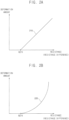
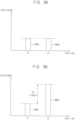
- FIG. 2A is a diagram illustrating an example of a resistance-deformation amount model
- FIG. 2B is a diagram illustrating another example of a resistance-deformation amount model
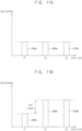
- FIG. 3A is a diagram illustrating an example of a resistance-voltage drop model
- FIG. 3B is a diagram illustrating another example of a resistance-voltage drop model according to an embodiment.
- a flexible display device 100 may include a flexible display panel 110, a power management circuit 120 that supplies a power supply voltage ELVDD to the flexible display panel 110, and a display driver 130 that drives the flexible display panel 110.
- the display driver 130 may include a data driver 140 that provides data signals DS to the flexible display panel 110, and a controller 160 that controls an operation of the flexible display device 100.
- the flexible display device 100 may further include a scan driver 150 that provides scan signals SS to the flexible display panel 110.
- the flexible display panel 110 may be any deformable display panel.
- the flexible display panel 110 may be any flexible display panel, such as a foldable display panel, a rollable display panel, a curved display panel, a bended display panel, a stretchable display panel, or the like.
- the flexible display panel 110 may include a plurality of pixels PX in a display region DR therein (See FIG. 4 ).
- each pixel PX may include a light emitting element
- the flexible display panel 110 may be a light emitting display panel.
- the flexible display panel 110 may be, but not limited to, an organic light emitting diode (“OLED”) display panel, a quantum dot (“QD”) display panel, or the like.
- the flexible display panel 110 may be a liquid crystal display (“LCD”) panel, or any other suitable display panel.
- the flexible display panel 110 may further include a power supply line coupled to the plurality of pixels PX.
- the power supply line may be a line for supplying the power supply voltage ELVDD (e.g., a high-power supply voltage) generated by the power management circuit 120 to the plurality of pixels PX.
- the power supply line may have, but not limited to, a mesh structure.
- the flexible display panel 110 may further include at least one measuring line ML.
- a resistance of the at least one measuring line ML may be sensed or measured to detect a deformation position and/or a deformation amount (or a deformation degree) of the flexible display panel 110.
- the at least one measuring line ML may be an outer measuring line OML surrounding the display region DR in which the plurality of pixels PX is disposed. In other embodiments, as illustrated in FIGS.
- the at least one measuring line ML may include a plurality of measuring lines ML1, ML2, ML3, ..., MLN-1 and MLN extending to a plurality of positions P1, P2, P3, ..., PN-1 and PN, respectively.
- the power management circuit 120 may supply the power supply voltage ELVDD to the plurality of pixels PX through the power supply line. In some embodiments, the power management circuit 120 may adjust a voltage level of the power supply voltage ELVDD in response to a power control signal PCTRL received from the controller 160. In some embodiments, the power management circuit 120 may be implemented with an integrated circuit, and the integrated circuit may be referred to as a power management integrated circuit ("PMIC"). In other embodiments, the power management circuit 120 may be included in the display driver 130 or the controller 160.
- PMIC power management integrated circuit
- the data driver 140 may generate the data signals DS based on output image data ODAT and a data control signal DCTRL received from the controller 160, and may provide the data signals DS to the plurality of pixels PX through a plurality of data lines.
- the data control signal DCTRL may include, but not limited to, a data enable signal, a horizontal start signal and a load signal.
- the data driver 140 and the controller 160 may be implemented with a single integrated circuit, and the single integrated circuit may be referred to as a timing controller embedded data driver ("TED") integrated circuit. In other embodiments, the data driver 140 and the controller 160 may be implemented with separate integrated circuits from each other.
- TED timing controller embedded data driver
- the scan driver 150 may generate the scan signals SS based on a scan control signal SCTRL received from the controller 160, and may sequentially provide the scan signals SS to the plurality of pixels PX on a row-by-row basis through a plurality of scan lines.
- the scan control signal SCTRL may include, but not limited to, a scan start signal and a scan clock signal.
- the scan driver 150 may be integrated or disposed in a peripheral region adjacent to (or within) the display region of the flexible display panel 110. In other embodiments, the scan driver 150 may be implemented with one or more integrated circuits.
- the controller 160 may receive input image data IDAT and a control signal CTRL from an external host processor (e.g., an application processor ("AP”), a graphics processing unit (“GPU”) or a graphics card).
- an external host processor e.g., an application processor ("AP"), a graphics processing unit (“GPU”) or a graphics card.
- the input image data IDAT may be, but not limited to, RGB image data including red image data, green image data and blue image data.
- the control signal CTRL may include, but not limited to, a vertical synchronization signal, a horizontal synchronization signal, an input data enable signal, a master clock signal, etc.
- the controller 160 may generate the output image data ODAT based on the input image data IDAT, and may generate the data control signal DCTRL and the scan control signal SCTRL based on the control signal CTRL.
- the controller 160 may control an operation of the data driver 140 by providing the output image data ODAT and the data control signal DCTRL to the data driver 140, and may control an operation of the scan driver 150 by providing the scan control signal SCTRL to the scan driver 150.
- the display driver 130 may sense (or measure) the resistance of the at least one measuring line ML of the flexible display panel 110.
- the display driver 130 may apply a current IM to a first end of the measuring line ML, may measure a voltage VM of a second end of the measuring line ML (or a voltage between the first end and a second end of the measuring line ML), and may determine the resistance of the measuring line ML based on the current IM and the voltage VM (e.g., using ohm's law).
- the display driver 130 may detect at least one of the deformation position and the deformation amount (or the deformation degree) of the flexible display panel 110 based on the sensed resistance of the at least one measuring line ML.
- the display driver 130 may generate deformation information DI representing at least one of the deformation position and the deformation amount, and may provide the deformation information DI to the external host processor.
- the flexible display panel 110 may have one or more fixed bendable positions, and the display driver 130 may determine one of the fixed bendable positions as the deformation position of the flexible display panel 110 based on the sensed resistance of the at least one measuring line ML.
- the flexible display panel 110 may include, as the at least one measuring line ML, the plurality of measuring lines extending from the display driver 130 to different positions.
- the display driver 130 may determine two measuring lines extending to adjacent two positions, respectively, and having a resistance difference greater than a reference resistance therebetween among the plurality of measuring lines, and may determine that the deformation position of the flexible display panel 110 is between the adjacent two positions.
- the display driver 130 may include a resistance-deformation amount model storage 170 that stores resistance-deformation amount model information about a deformation amount value of the flexible display panel 110 corresponding to a resistance value (or a resistance difference value) of the at least one measuring line ML.
- the display driver 130 may determine the deformation amount of the flexible display panel 110 corresponding to the sensed resistance of the at least one measuring line ML by using the resistance-deformation amount model information stored in the resistance-deformation amount model storage 170.
- the resistance-deformation amount model information may be stored as various forms, for example, a lookup table or an equation.
- the resistance-deformation amount model information stored in the resistance-deformation amount model storage 170 may be determined through experiments for the flexible display device 100.
- the resistance-deformation amount model information stored in the resistance-deformation amount model storage 170 may represent a linear relationship 210 between the resistance value (or the resistance difference value) greater than the reference resistance REFR and the deformation amount value.
- the linear relationship 210 and the reference resistance REFR may be determined through the experiments for the flexible display device 100.
- FIG. 2A the resistance-deformation amount model information stored in the resistance-deformation amount model storage 170 may represent a linear relationship 210 between the resistance value (or the resistance difference value) greater than the reference resistance REFR and the deformation amount value.
- the linear relationship 210 and the reference resistance REFR may be determined through the experiments for the flexible display device 100.
- the resistance-deformation amount model information stored in the resistance-deformation amount model storage 170 may represent a nonlinear relationship 220 between the resistance value (or the resistance difference value) greater than the reference resistance REFR and the deformation amount value.
- the nonlinear relationship 220 may correspond to, but not limited to, a second-order equation of the resistance value and the deformation amount value.
- the nonlinear relationship 220 and the reference resistance REFR may be determined through the experiments for the flexible display device 100.
- the resistance-deformation amount model storage 170 may be implemented in a form of a lookup table that outputs a corresponding deformation amount value in response to each resistance value (or each resistance difference value), but a configuration of the resistance-deformation amount model storage 170 is not limited to the lookup table.
- the flexible display device 100 may compensate the power supply voltage ELVDD supplied to the flexible display panel 110 based on the sensed resistance of the at least one measuring line ML.
- resistances of lines of the flexible display panel 110 for example a resistance of the power supply line for supplying the power supply voltage ELVDD may be increased, and a voltage drop of the power supply voltage ELVDD may be increased by the increase of the resistance.
- the flexible display device 100 may increase the power supply voltage ELVDD to compensate for the voltage drop of the power supply voltage ELVDD.
- deformed means folded, bent, rolled, curved or stretched.
- the display driver 130 may include a resistance-voltage drop model storage 180 that stores resistance-voltage drop model information about a voltage drop amount of the power supply voltage ELVDD at the power supply line corresponding to the resistance value (or the resistance difference value) of the at least one measuring line ML.
- the display driver 130 may determine the voltage drop amount of the power supply voltage ELVDD corresponding to the sensed resistance of the at least one measuring line ML by using the resistance-voltage drop model information stored in the resistance-voltage drop model storage 180, and may provide the power control signal PCTRL representing an increased voltage level of the power supply voltage ELVDD to the power management circuit 120 to increase a voltage level of the power supply voltage ELVDD by the determined voltage drop amount.
- the power management circuit 120 may increase the voltage level of the power supply voltage ELVDD by the determined voltage drop amount in response to the power control signal PCTRL.
- the resistance-voltage drop model information may be stored as various forms, for example, a lookup table or an equation.
- the resistance-voltage drop model information stored in the resistance-voltage drop model storage 180 may be determined through experiments for the flexible display device 100.
- the resistance-voltage drop model information stored in the resistance-voltage drop model storage 180 may represent a linear relationship 260 between the resistance value (or the resistance difference value) greater than the reference resistance REFR and the voltage drop amount of the power supply voltage ELVDD.
- the resistance-voltage drop model information stored in the resistance-voltage drop model storage 180 may represent a nonlinear relationship 270 between the resistance value (or the resistance difference value) greater than the reference resistance REFR and the voltage drop amount of the power supply voltage ELVDD.
- the nonlinear relationship 270 may correspond to, but not limited to, a second-order equation of the resistance value and the voltage drop amount.
- the resistance-voltage drop model storage 180 may be implemented in a form of a lookup table that outputs a corresponding voltage drop amount in response to each resistance value (or each resistance difference value), but a configuration of the resistance-voltage drop model storage 180 is not limited to the lookup table.
- the display driver 130 may sense the resistance of the at least one measuring line ML, and may detect at least one of the deformation position and the deformation amount of the flexible display panel 110 based on the sensed resistance of the at least one measuring line ML. Accordingly, the deformation position and/or the deformation amount of the flexible display panel 110 may be efficiently and accurately detected. Further, in the flexible display device 100 according to embodiments, the power supply voltage ELVDD may be compensated based on the deformation position and/or the deformation amount. Accordingly, even if the flexible display panel 110 is deformed, deterioration of luminance uniformity and color deviation of the flexible display panel 110 may be prevented or reduced.
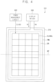
- FIG. 4 is a diagram illustrating a flexible display device having one fixed bendable position according to embodiments
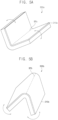
- FIG. 5A is a diagram illustrating an example of a flexible display device according to embodiments
- FIG. 5B is a diagram illustrating another example of a flexible display device according to embodiments
- FIG. 6 is a diagram illustrating an example of resistances of an outer measuring line before and after bending of a flexible display panel.
- a flexible display device 300 may include a flexible display panel 310, a power management circuit 320 that supplies a power supply voltage ELVDD to the flexible display panel 310, and a display driver 330 that drives the flexible display panel 310.
- the flexible display panel 310 may include a plurality of pixels formed in a display region DR, and a power supply line ELVDDL coupled to the plurality of pixels.
- the power management circuit 320 may supply the power supply voltage ELVDD to the plurality of pixels through the power supply line ELVDDL.
- the power supply line ELVDDL may have a mesh structure.
- the flexible display panel 310 may be a foldable display panel having a fixed bendable position BP
- the flexible display device 300 may be a foldable display device.
- the flexible display device 300 may be an infoldable display device 300a including the foldable display panel 310a that is folded at the fixed bendable position BPa such that portions of the display region DR of the foldable display panel 310a face each other when folded.
- FIG. 5A the flexible display device 300 may be an infoldable display device 300a including the foldable display panel 310a that is folded at the fixed bendable position BPa such that portions of the display region DR of the foldable display panel 310a face each other when folded.
- the flexible display device 300 may be an out-foldable display device 300b including the foldable display panel 310b that is folded at the fixed bendable position BPb such that a portion of the display region DR is located at a front side (e.g., facing a viewer) and another portion of the display region DR is located at a back side (e.g., facing away from the viewer) when folded.
- FIGS. 5A and 5B illustrate examples where the flexible display device 300 is the foldable display device 300a and 300b
- the flexible display device 300 may be any flexible display device, such as a rollable display device, a curved display device, a bended display device, a stretchable display device, or the like.
- the flexible display panel 310 may further include an outer measuring line OML surrounding the display region DR of the flexible display panel 310.
- the display driver 330 may apply a current IL to a first end of the outer measuring line OML, and may sense a resistance of the outer measuring line OML by measuring a voltage VM of a second end of the outer measuring line OML. Based on the sensed resistance of the outer measuring line OML, the display driver 330 may determine where the flexible display panel 310 is deformed, and may determine a deformation amount of the flexible display panel 310.
- the display driver 330 may determine that the flexible display panel 310 is not deformed.
- the display driver 330 may determine that the flexible display panel 310 is deformed, for example that the flexible display panel 310 is folded or bent. Further, the display driver 330 may determine the deformation amount of the flexible display panel 310 corresponding to the resistance 350 of the outer measuring line OML.
- the display driver 330 may store resistance-deformation amount model information about a deformation amount value of the flexible display panel 310 corresponding to a resistance value of the outer measuring line OML, and may determine the deformation amount of the flexible display panel 310 corresponding to the resistance 350 of the outer measuring line OML by using the resistance-deformation amount model information.
- the flexible display device 300 may compensate or increase the power supply voltage ELVDD supplied to the flexible display panel 310 based on the resistance 350 of the outer measuring line OML.
- the display driver 330 may store resistance-voltage drop model information about a voltage drop amount of the power supply voltage ELVDD at the power supply line ELVDDL corresponding to the resistance value of the outer measuring line OML, may determine the voltage drop amount of the power supply voltage ELVDD corresponding to the resistance 350 of the outer measuring line OML by using the resistance-voltage drop model information, and may increase a voltage level of the power supply voltage ELVDD by the determined voltage drop amount. Accordingly, even if the flexible display panel 310 is deformed, deterioration of an image quality of the flexible display panel 310 may be prevented or reduced.
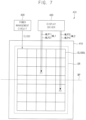
- FIG. 7 is a diagram illustrating a flexible display device having one fixed bendable position according to embodiments
- FIG. 8A is a diagram illustrating an example of resistances of first and second measuring lines in a case where a flexible display panel is not bent
- FIG. 8B is a diagram illustrating an example of resistances of first and second measuring lines in a case where a flexible display panel is bent.
- a flexible display device 400 may include a flexible display panel 410, a power management circuit 420 and a display driver 430.
- the flexible display device 400 of FIG. 7 may have a similar configuration and a similar operation to a flexible display device 300 of FIG. 4 , except that the flexible display panel 410 may include first and second measuring lines ML1 and ML2 instead of an outer measuring line OML.
- the flexible display panel 410 may be a foldable display panel having a fixed bendable position BP, and may include a first measuring line ML1 extending from the display driver 430 to a first position P1, and a second measuring line ML2 extending from the display driver 430 to a second position P2.
- the first position P1 and the second position P2 are located in the flexible display panel 410.
- the first position P1 may be closer to the display driver 430 than the bendable position BP, and the second position P2 may be farther from the display driver 430 than the bendable position BP. For example, as illustrated in FIG.
- the first measuring line ML1 may include a first portion MLP1 extending from the display driver 430 to the first position P1 and a second portion MLP2 extending from the first position P1 to the display driver 430
- the second measuring line ML2 may include a third portion MLP3 extending from the display driver 430 to the second position P2 and a fourth portion MLP4 extending from the second position P2 to the display driver 430.
- the display driver 430 may sense a resistance of the first measuring line ML1 and a resistance of the second measuring line ML2. For example, the display driver 430 may sense the resistance of the first measuring line ML1 by applying a current to one end of the first measuring line ML1 and by measuring a voltage of the other end of the first measuring line ML1, and may sense the resistance of the second measuring line ML2 by applying a current to one end of the second measuring line ML2 and by measuring a voltage of the other end of the second measuring line ML2. Based on a difference between the resistance of the first measuring line ML1 and the resistance of the second measuring line ML2, the display driver 430 may determine where the flexible display panel 410 is deformed, and may determine a deformation amount of the flexible display panel 410.
- the display driver 430 may determine that the flexible display panel 410 is not deformed.
- the reference resistance REFR may be determined through experiments for the flexible display device 400.
- the resistances 450a and 460a of the first and second measuring lines ML1 and ML2 may have a (small) difference RD less than the reference resistance REFR when the flexible display panel 410 is not deformed.
- the display driver 430 may determine that the flexible display panel 410 is deformed, for example that the flexible display panel 410 is folded or bent.
- the display driver 430 may determine the deformation amount of the flexible display panel 410 corresponding to the difference RD between the resistances 450b and 460b of the first and second measuring lines ML1 and ML2.
- the display driver 430 may store resistance-deformation amount model information about a deformation amount value of the flexible display panel 410 corresponding to a resistance difference value of the first and second measuring lines ML1 and ML2, and may determine the deformation amount of the flexible display panel 410 corresponding to the difference RD between the resistances 450b and 460b of the first and second measuring lines ML1 and ML2 by using the resistance-deformation amount model information.
- the flexible display device 400 may compensate or increase a power supply voltage ELVDD supplied to the flexible display panel 410 based on the difference RD between the resistances 450b and 460b of the first and second measuring lines ML1 and ML2.
- the display driver 430 may store resistance-voltage drop model information about a voltage drop amount of the power supply voltage ELVDD at a power supply line ELVDDL corresponding to the resistance difference value of the first and second measuring lines ML1 and ML2, may determine the voltage drop amount of the power supply voltage ELVDD corresponding to the difference RD between the resistances 450b and 460b of the first and second measuring lines ML1 and ML2 by using the resistance-voltage drop model information, and may increase a voltage level of the power supply voltage ELVDD by the determined voltage drop amount. Accordingly, even if the flexible display panel 410 is deformed, deterioration of an image quality of the flexible display panel 410 may be prevented or reduced.
- FIG. 9 is a diagram illustrating a flexible display device having two fixed bendable positions according to embodiments
- FIG. 10 is a diagram illustrating an example of a flexible display device according to embodiments
- FIG. 11A is a diagram illustrating an example of resistances of first through third measuring lines in a case where a flexible display panel is not bent
- FIG. 11B is a diagram illustrating an example of resistances of first through third measuring lines in a case where a flexible display panel is bent at a first bendable position
- FIG. 11C is a diagram illustrating an example of resistances of first through third measuring lines in a case where a flexible display panel is bent at a second bendable position
- FIG. 11D is a diagram illustrating an example of resistances of first through third measuring lines in a case where a flexible display panel is bent at first and second bendable positions.
- a flexible display device 500 may include a flexible display panel 510, a power management circuit 520 and a display driver 530.
- the flexible display device 500 of FIG. 9 may have a similar configuration and a similar operation to a flexible display device 300 of FIG. 4 or a flexible display device 400 of FIG. 7 , except that the flexible display panel 510 may have two fixed bendable positions BP1 and BP2, and may include first, second and third measuring lines ML1, ML2 and ML3 extending to first, second and third positions P1, P2 and P3, respectively.
- the first, second and third positions P1, P2 and P3 are located in the flexible display panel 510.
- the flexible display panel 510 may be a foldable display panel having two fixed bendable positions BP1 and BP2.
- the flexible display device 500 may be a foldable display device including the flexible display panel 510 that is bent or folded at each of a first bendable position BP1 and a second bendable position BP2.
- the flexible display panel 510 may include a first measuring line ML1 extending from the display driver 530 to a first position P1, a second measuring line ML2 extending from the display driver 530 to a second position P2 and a third measuring line ML3 extending from the display driver 530 to a third position P3.
- the first position P1 may be closer to the display driver 530 than the first bendable position BP1
- the second position P2 may be farther from the display driver 530 than the first bendable position BP1 and closer to the display driver 530 than the second bendable position BP2
- the third position P3 may be farther from the display driver 530 than the second bendable position BP2.
- the display driver 530 may sense a resistance of the first measuring line ML1, a resistance of the second measuring line ML2 and a resistance of the third measuring line ML3. Further, the display driver 530 may detect a deformation position and a deformation amount of the flexible display panel 510 based on differences of the resistances of the first, second and third measuring lines ML1, ML2 and ML3. In some embodiments, based on the difference between the resistance of the first measuring line ML1 and the resistance of the second measuring line ML2, the display driver 530 may determine whether the flexible display panel 510 is deformed at the first bendable position BP1, and may determine the deformation amount of the flexible display panel 510 at the first bendable position BP1.
- the display driver 530 may determine whether the flexible display panel 510 is deformed at the second bendable position BP2, and may determine the deformation amount of the flexible display panel 510 at the second bendable position BP2.
- the display driver 530 may determine that the flexible display panel 510 is not deformed (e.g., neither folded nor bent). In another example, as illustrated in FIG. 11A , as illustrated in FIG. 11A , in a case where each of a first difference RD1 between resistances 550a and 560a of the first and second measuring lines ML1 and ML2 and a second difference RD2 between resistances 560a and 570a of the second and third measuring lines ML2 and ML3 is less than (or equal to) a reference resistance REFR, the display driver 530 may determine that the flexible display panel 510 is not deformed (e.g., neither folded nor bent). In another example, as illustrated in FIG.
- the display driver 530 may determine that the flexible display panel 510 is deformed (e.g., folded or bent) at the first bendable position BP1.
- the flexible display panel 510 is deformed (e.g., folded or bent) at the first bendable position BP1.
- the display driver 530 may determine that the flexible display panel 510 is deformed at the second bendable position BP2. In still another example, as illustrated in FIG.
- the display driver 530 may determine that the flexible display panel 510 is deformed (e.g., folded or bent) at both of the first bendable position BP1 and the second bendable position BP2.
- the display driver 530 may determine the deformation amount at the first bendable position BP1 corresponding to the first difference RD1 between the resistances 550d and 560d of the first and second measuring lines ML1 and ML2, and may determine the deformation amount at the second bendable position BP2 corresponding to the second difference RD2 between resistances 560d and 570d of the second and third measuring lines ML2 and ML3.
- the display driver 530 may store resistance-deformation amount model information about a deformation amount value corresponding to each resistance difference value, and may determine the deformation amount at the first bendable position BP1 corresponding to the first difference RD1 and the deformation amount at the second bendable position BP2 corresponding to the second difference RD2 by using the resistance-deformation amount model information.
- the flexible display device 500 may compensate or increase a power supply voltage ELVDD supplied to the flexible display panel 510 based on the differences RD1 and RD2 between the resistances 550d, 560d and 570d of the first, second and third measuring lines ML1, ML2 and ML3. Further, in some embodiments, the flexible display device 500 may compensate or increase the power supply voltage ELVDD based on a greater one of the differences RD1 and RD2 between the resistances 550d, 560d and 570d.
- the display driver 530 may store resistance-voltage drop model information about a voltage drop amount of the power supply voltage ELVDD corresponding to each resistance difference value, may determine the voltage drop amount of the power supply voltage ELVDD corresponding to the second difference RD2 between the resistances 560d and 570d of the second and third measuring lines ML2 and ML3 by using the resistance-voltage drop model information in a case where the second difference RD2 between the resistances 560d and 570d of the second and third measuring lines ML2 and ML3 is greater than the first difference RD1 between the resistances 550d and 560d of the first and second measuring lines ML1 and ML2, and may increase a voltage level of the power supply voltage ELVDD by the determined voltage drop amount. Accordingly, even if the flexible display panel 510 is deformed, deterioration of an image quality of the flexible display panel 510 may be prevented or reduced.
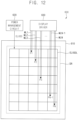
- FIG. 12 is a diagram illustrating a flexible display device including a foldable display panel that is able to be bent at any position according to embodiments
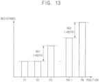
- FIG. 13 is a diagram illustrating an example of resistances of a plurality of measuring lines in a case where a flexible display panel is bent.
- a flexible display device 600 may include a flexible display panel 610, a power management circuit 620 and a display driver 630.
- the flexible display device 600 of FIG. 12 may have a similar configuration and a similar operation to a flexible display device 300, 400 or 500 of FIG. 4 , FIG. 7 or FIG. 9 , except that the flexible display panel 610 is able to be bent or folded at any position, and may include a plurality of measuring lines ML1, ML2, ML3, ..., MLN-1 and MLN extending to a plurality of positions P1, P2, P3, ..., PN-1 and PN, respectively.
- the plurality of positions P1, P2, P3, ..., PN-1 and PN is located in the flexible display panel 610.
- the flexible display panel 610 may be a foldable display panel that is able to be bent or folded at any position.
- the flexible display panel 610 may include first through N-th measuring lines ML1 through MLN extending from the display driver 630 to first through N-th positions P1 through PN, where N is an integer greater than 1.
- the first through N-th positions P1 through PN may have, but not limited to, a regular interval.
- the display driver 630 may sense resistances of the first through N-th measuring lines ML1 through MLN. Further, the display driver 630 may detect a deformation position and a deformation amount of the flexible display panel 610 based on differences of the resistances of the first through N-th measuring lines ML1 through MLN. In some embodiments, in a case where a difference between the resistances of two measuring lines extending to adjacent two positions among the first through N-th measuring lines ML1 through MLN is greater than a reference resistance, the display driver 630 may determine that the deformation position of the flexible display panel 610 is between the adjacent two positions. Further, in some embodiments, the display driver 630 may determine the deformation amount of the flexible display panel 610 at the deformation position based on the difference between the resistances of the two measuring lines.
- the display driver 630 may determine that the flexible display panel 610 is deformed at a first deformation position (e.g., a first bendable position) between the second position P2 and the third position P3, and that the flexible display panel 610 is further deformed at a second deformation position (e.g., a second bendable position) between the (N-1)-th position PN-1 and the N-th position PN.
- a first deformation position e.g., a first bendable position
- a second deformation position e.g., a second bendable position
- the flexible display device 600 may compensate or increase a power supply voltage ELVDD supplied to the flexible display panel 610 based on the differences of the resistances of the first through N-th measuring lines ML1 through MLN. Further, in some embodiments, the flexible display device 600 may compensate or increase the power supply voltage ELVDD based on a greatest one of the differences of the resistances.
- the display driver 630 may determine a voltage drop amount of the power supply voltage ELVDD corresponding to the second difference RD2 between the resistances of the (N-1)-th and N-th measuring lines MLN-1 and MLN, and may increase a voltage level of the power supply voltage ELVDD by the determined voltage drop amount. Accordingly, even if the flexible display panel 610 is deformed, deterioration of an image quality of the flexible display panel 610 may be prevented or reduced.
- FIG. 14 is a block diagram illustrating a flexible display device according to embodiments
- FIG. 15A is a diagram illustrating an example of a resistance-data compensation model
- FIG. 15B is a diagram illustrating another example of a resistance-data compensation model.
- a flexible display device 700 may include a flexible display panel 710, a power management circuit 720 and a display driver 730.
- the display driver 730 may include a data driver 740 and a controller 760.
- the controller 760 may include a resistance-deformation amount model storage 770 and a resistance-data compensation model storage 780.
- the resistance-deformation amount model storage 170, the resistance-voltage drop model storage 180, the resistance-deformation amount model storage 770, and the resistance-data compensation model storage 780 may be implemented by a storage device such as memory.
- the flexible display device 700 may further include a scan driver 750.
- the display driver 730 may include the resistance-data compensation model storage 780, and may compensate input image data IDAT instead of or along with a power supply voltage ELVDD based on a resistance of at least one measuring line ML.
- the resistance-data compensation model storage 780 may store resistance-data compensation model information about a data compensation value corresponding to a resistance value (or a resistance difference value) of the at least one measuring line ML.
- the display driver 730 may sense a resistance of the at least one measuring line ML, and may generate output image data ODAT by compensating the input image data IDAT based on the sensed resistance of the at least one measuring line ML and the resistance-data compensation model information stored in the resistance-data compensation model storage 780.
- the display driver 730 may determine the data compensation value corresponding to the sensed resistance of the at least one measuring line ML based on the resistance-data compensation model information, and may generate the output image data ODAT for each pixel PX by adding the data compensation value to a gray level represented by the input image data IDAT with respect to each pixel PX.
- the resistance-data compensation model information may be stored as various forms, for example, a lookup table or an equation.
- the resistance-data compensation model information stored in the resistance-data compensation model storage 780 may be determined through experiments for the flexible display device 700.
- the resistance-data compensation model information stored in the resistance-data compensation model storage 780 may represent a linear relationship 810 between the resistance value (or the resistance difference value) greater than a reference resistance REFR and the data compensation value.
- the resistance-data compensation model information stored in the resistance-data compensation model storage 780 may represent a nonlinear relationship 820 between the resistance value (or the resistance difference value) greater than the reference resistance REFR and the data compensation value.
- the nonlinear relationship 820 may correspond to, but not limited to, a second-order equation of the resistance value and the data compensation value.
- the resistance-data compensation model storage 780 may be implemented in a form of a lookup table that outputs a corresponding data compensation value in response to each resistance value (or each resistance difference value), but a configuration of the resistance-data compensation model storage 780 is not limited to the lookup table.
- the display driver 730 may sense the resistance of the at least one measuring line ML, and may detect at least one of a deformation position and a deformation amount of the flexible display panel 710 based on the sensed resistance of the at least one measuring line ML. Further, in the flexible display device 700 according to embodiments, the input image data IDAT may be compensated based on the deformation position and/or the deformation amount. Accordingly, even if the flexible display panel 710 is deformed, deterioration of luminance uniformity and color deviation of the flexible display panel 710 may be prevented or reduced.
- FIG. 16 is a diagram for describing an example where input image data are compensated in a flexible display device having one fixed bendable position.
- a flexible display panel 310/410 of a flexible display device 300/400 may have one fixed bendable position BP.
- the flexible display device 300/400 may be a flexible display device 300 of FIG. 4 or a flexible display device 400 of FIG. 7 .
- the flexible display panel 310/410 may include, as least one measuring line, an outer measuring line OML as illustrated in FIG. 4 , or first and second measuring lines ML1 and ML2 corresponding to first and second positions P1 and P2 as illustrated in FIG. 7 .
- a power supply voltage ELVDD may be decreased by a voltage drop VD at the bendable position BP and positions farther from the display driver 330/430 than the bendable position BP as illustrated as a graph 830.
- the flexible display device 300/400 may sense a resistance of the at least one measuring line, and may generate output image data ODAT by increasing input image data IDAT for a plurality of pixels located farther from the display driver 330/430 than the bendable position BP (e.g., for a plurality of pixels located at a lower portion below the bendable position BP) by a data compensation value DCV based on the resistance of the as least one measuring line as illustrated as a graph 840. Accordingly, even if the flexible display panel 310/410 is deformed, deterioration of an image quality of the flexible display panel 310/410 may be effectively prevented or reduced.
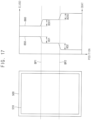
- FIG. 17 is a diagram for describing an example where input image data are compensated in a flexible display device having two fixed bendable positions.
- a flexible display panel 510 of a flexible display device 500 may have two fixed bendable position BP1 and BP2.
- the flexible display panel 510 may include, as least one measuring line, first, second and third measuring lines ML1, ML2 and ML3 corresponding to first, second and third positions P1, P2 and P3 as illustrated in FIG. 9 .
- a power supply voltage ELVDD may be decreased by first and second voltage drops VD1 and VD2 at the first and second bendable positions BP1 and BP2 as illustrated as a graph 850.
- the flexible display device 500 may sense a resistance of the as least one measuring line, and may generate output image data ODAT by increasing input image data IDAT for a plurality of pixels located farther from the display driver 330/430 than the first bendable position BP1 (e.g., for a plurality of pixels located at a lower portion below the first bendable position BP1) by a first data compensation value DCV1 and by further increasing the input image data IDAT for a plurality of pixels located farther from the display driver 330/430 than the second bendable position BP2 (e.g., for a plurality of pixels located at a lower portion below the second bendable position BP2) by a second data compensation value DCV2 based on the resistance of the as least one measuring line as illustrated as a graph 860. Accordingly, even if the flexible display panel 510 is deformed, deterioration of an image quality of the flexible display panel 510 may be effectively prevented or reduced.
- FIG. 18 is a diagram for describing an example where input image data are compensated in a flexible display device including a foldable display panel that is able to be bent at any position.
- a flexible display panel 610 of a flexible display device 600 may be deformed (e.g., bent or folded) at any position.
- the flexible display panel 610 may include, as least one measuring line, first through N-th measuring lines ML1 through MLN corresponding to first through N-th positions P1 through PN as illustrated in FIG. 12 .
- the flexible display device 600 may determine that the first bendable position BP1 is between the second position P2 and the third position P3 and that the second bendable position BP2 is between the (N-1)-th position PN-1 and the N-th position PN by sensing resistances of the first through N-th measuring lines ML1 through MLN Further, if the flexible display panel 610 is deformed at the first and second bendable positions BP1 and BP2, a power supply voltage ELVDD may be decreased by first and second voltage drops VD1 and VD2 at the first and second bendable positions BP1 and BP2 as illustrated as a graph 870.
- a power supply voltage ELVDD may be decreased by first and second voltage drops VD1 and VD2 at the first and second bendable positions BP1 and BP2 as illustrated as a graph 870.
- the flexible display device 600 may generate output image data ODAT by gradually increasing input image data IDAT by up to a first data compensation value DCV1 between the second position P2 and the third position P3, by keeping the first data compensation value DCV1 between the third position P3 and the (N-1)-th position PN-1 and by further gradually increasing the input image data IDAT by up to a second data compensation value DCV2 between the (N-1)-th position PN-1 and the N-th position PN. Accordingly, even if the flexible display panel 610 is deformed, deterioration of an image quality of the flexible display panel 610 may be effectively prevented or reduced.
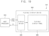
- FIG. 19 is a block diagram illustrating an electronic device including a flexible display device according to embodiments
- FIG. 20 is a diagram for describing an example where a region displaying a moving image is changed in a case where a flexible display panel is deformed.
- an electronic device 900 may include a host processor 910 and a flexible display device 920.
- the electronic device 900 may further include a memory device, a storage device, an input/output device, a power supply, etc.
- the host processor 910 may control an overall operation of the electronic device 900.
- the host processor 910 may be an application processor (AP) including a graphics processing unit (GPU), a microprocessor, a central processing unit (“CPU”), etc.
- the host processor 910 may generate input image data IDAT and a control signal CTRL, and may provide the input image data IDAT and the control signal CTRL to the flexible display device 920. Further, the host processor 910 may receive deformation information DI representing a deformation position and/or a deformation amount of a flexible display panel 930 from the flexible display device 920.
- the flexible display device 920 may display an image based on the input image data IDAT.
- the flexible display device 920 may include the flexible display panel 930 including a plurality of pixels, and a display driver 940 that drives the flexible display panel 930.
- the flexible display panel 930 may further include at least one measuring line.
- the display driver 940 may sense a resistance of the at least one measuring line, and may detect at least one of the deformation position and the deformation amount of the flexible display panel 930 based on the sensed resistance.
- the display driver 940 may provide the deformation information DI representing at least one of the deformation position and the deformation amount to the host processor 910.
- the host processor 910 may control a user interface based on the deformation information DI. For example, as illustrated in FIG. 20 , in a case where, while the flexible display panel 930 displays a moving image or a video, the host processor 910 receives the deformation information DI indicating that the flexible display panel 930 is deformed, the host processor 910 may adjust the input image data IDAT in response to the deformation information DI such that a region of the flexible display panel 930 displaying the moving image is changed.
- the host processor 910 may adjust the input image data IDAT such that the moving image is displayed at a first area 932 of the display region of the flexible display panel 930. Further, in some embodiments, the host processor 910 may adjust the input image data IDAT such that no image is displayed at a second area 934 of the display region of the flexible display panel 930, or such that a user interface image (e.g., a keyboard image or information image) is displayed at the second area 934 of the display region of the flexible display panel 930.
- a user interface image e.g., a keyboard image or information image
- the inventive concepts may be applied to any electronic device 900 including the flexible display device 920, such as a mobile phone, a smart phone, a tablet computer, a television ("TV”), a digital TV, a 3D TV, a wearable electronic device, a personal computer (“PC”), a home appliance, a laptop computer, a personal digital assistant (“PDA”), a portable multimedia player (“PMP”), a digital camera, a music player, a portable game console, a navigation device, etc.
- a mobile phone such as a mobile phone, a smart phone, a tablet computer, a television (“TV”), a digital TV, a 3D TV, a wearable electronic device, a personal computer (“PC”), a home appliance, a laptop computer, a personal digital assistant (“PDA”), a portable multimedia player (“PMP”), a digital camera, a music player, a portable game console, a navigation device, etc.
- TV television
- PMP portable multimedia player
- PMP portable multimedia player
Landscapes
- Engineering & Computer Science (AREA)
- Physics & Mathematics (AREA)
- General Physics & Mathematics (AREA)
- Computer Hardware Design (AREA)
- Theoretical Computer Science (AREA)
- Electroluminescent Light Sources (AREA)
- Control Of El Displays (AREA)
- Control Of Indicators Other Than Cathode Ray Tubes (AREA)
- Devices For Indicating Variable Information By Combining Individual Elements (AREA)
Applications Claiming Priority (1)
| Application Number | Priority Date | Filing Date | Title |
|---|---|---|---|
| KR1020210144861A KR102901559B1 (ko) | 2021-10-27 | 2021-10-27 | 플렉서블 표시 장치 및 이를 포함하는 전자 기기 |
Publications (2)
| Publication Number | Publication Date |
|---|---|
| EP4174831A2 true EP4174831A2 (de) | 2023-05-03 |
| EP4174831A3 EP4174831A3 (de) | 2023-06-21 |
Family
ID=84043878
Family Applications (1)
| Application Number | Title | Priority Date | Filing Date |
|---|---|---|---|
| EP22203880.4A Pending EP4174831A3 (de) | 2021-10-27 | 2022-10-26 | Flexible anzeigevorrichtung und elektronische vorrichtung damit |
Country Status (4)
| Country | Link |
|---|---|
| US (1) | US11847947B2 (de) |
| EP (1) | EP4174831A3 (de) |
| KR (1) | KR102901559B1 (de) |
| CN (1) | CN116030744A (de) |
Families Citing this family (4)
| Publication number | Priority date | Publication date | Assignee | Title |
|---|---|---|---|---|
| US11892286B2 (en) * | 2013-09-17 | 2024-02-06 | Medibotics Llc | Motion recognition clothing [TM] with an electroconductive mesh |
| KR20240094643A (ko) * | 2022-12-16 | 2024-06-25 | 엘지디스플레이 주식회사 | 표시장치 및 이의 구동방법 |
| CN117116204A (zh) * | 2023-08-28 | 2023-11-24 | 合肥工业大学 | 一种显示面板电压降的补偿方法、系统、设备及介质 |
| KR20250160296A (ko) * | 2024-05-03 | 2025-11-12 | 삼성디스플레이 주식회사 | 폴더블 표시 장치 및 이를 구동하는 방법 |
Family Cites Families (19)
| Publication number | Priority date | Publication date | Assignee | Title |
|---|---|---|---|---|
| CN1265338C (zh) * | 2001-11-21 | 2006-07-19 | 佳能株式会社 | 显示装置、其图像信号处理装置及驱动控制装置 |
| TWI320167B (en) * | 2006-09-07 | 2010-02-01 | Display device and method capable of adjusting slew rate | |
| JP5640365B2 (ja) * | 2009-12-07 | 2014-12-17 | ソニー株式会社 | 表示装置及び表示装置の制御方法 |
| KR101692252B1 (ko) * | 2012-04-08 | 2017-01-04 | 삼성전자주식회사 | 플렉서블 디스플레이 장치 및 제어 방법 |
| KR102104588B1 (ko) * | 2012-07-11 | 2020-04-24 | 삼성전자주식회사 | 플렉서블 디스플레이 장치 및 그 동작 방법 |
| KR102190140B1 (ko) * | 2014-09-15 | 2020-12-14 | 삼성디스플레이 주식회사 | 스트레쳐블 표시 장치 및 이의 휘도 보상 방법 |
| US9741772B2 (en) * | 2014-12-26 | 2017-08-22 | Lg Display Co., Ltd. | Display device comprising bending sensor |
| KR102281902B1 (ko) | 2015-02-05 | 2021-07-28 | 삼성디스플레이 주식회사 | 표시장치 및 이의 구동방법 |
| KR102362741B1 (ko) * | 2015-05-27 | 2022-02-14 | 삼성전자주식회사 | 플렉서블 디스플레이 장치 및 플렉서블 디스플레이 장치의 디스플레이 방법 |
| US10585456B2 (en) * | 2015-08-26 | 2020-03-10 | Lg Display Co., Ltd. | Flexible display device having bending sensing device |
| KR102424860B1 (ko) | 2015-11-04 | 2022-07-26 | 삼성디스플레이 주식회사 | 플렉서블 표시장치 및 그 구동방법 |
| KR102536791B1 (ko) * | 2016-07-29 | 2023-05-26 | 엘지디스플레이 주식회사 | 두루마리형 연성표시장치 |
| KR102801933B1 (ko) * | 2016-12-20 | 2025-05-07 | 삼성디스플레이 주식회사 | 표시 장치 |
| CN106910842B (zh) | 2017-04-17 | 2019-01-15 | 京东方科技集团股份有限公司 | 一种封装结构、柔性显示基板和柔性显示装置 |
| CN109427258B (zh) * | 2017-09-05 | 2021-09-17 | 乐金显示有限公司 | 显示装置 |
| KR102471919B1 (ko) | 2017-09-05 | 2022-11-28 | 엘지디스플레이 주식회사 | 표시 장치 |
| KR102510912B1 (ko) | 2018-03-19 | 2023-03-17 | 삼성디스플레이 주식회사 | 표시 장치 및 이의 크랙 검사 방법 |
| KR102625726B1 (ko) * | 2018-12-31 | 2024-01-15 | 엘지디스플레이 주식회사 | 발광 표시장치 |
| WO2021158038A1 (en) | 2020-02-04 | 2021-08-12 | Samsung Electronics Co., Ltd. | A method and a flexible apparatus managing a folding thereof |
-
2021
- 2021-10-27 KR KR1020210144861A patent/KR102901559B1/ko active Active
-
2022
- 2022-08-23 US US17/893,585 patent/US11847947B2/en active Active
- 2022-10-26 EP EP22203880.4A patent/EP4174831A3/de active Pending
- 2022-10-26 CN CN202211315400.2A patent/CN116030744A/zh active Pending
Also Published As
| Publication number | Publication date |
|---|---|
| EP4174831A3 (de) | 2023-06-21 |
| CN116030744A (zh) | 2023-04-28 |
| US20230125796A1 (en) | 2023-04-27 |
| KR102901559B1 (ko) | 2025-12-23 |
| US11847947B2 (en) | 2023-12-19 |
| KR20230060622A (ko) | 2023-05-08 |
Similar Documents
| Publication | Publication Date | Title |
|---|---|---|
| EP4174831A2 (de) | Flexible anzeigevorrichtung und elektronische vorrichtung damit | |
| US11217136B2 (en) | Display device supporting a partial driving mode, and method of operating a display device | |
| EP2804171B1 (de) | Anzeigevorrichtung und Verfahren zu ihrer Ansteuerung | |
| US8749541B2 (en) | Decreasing power consumption in display devices | |
| US11488524B2 (en) | Organic light emitting diode display device, and method of operating an organic light emitting diode display device | |
| US11386832B1 (en) | Tiled display device having a plurality of display panels | |
| US11107418B2 (en) | Luminance control device, display device including the same, and method of driving the same | |
| US20210166612A1 (en) | Flexible display device, and method of operating a flexible display device | |
| US20180005586A1 (en) | Display device and method for controlling peak luminance of the same | |
| US20230306888A1 (en) | Display device | |
| US8497887B2 (en) | Display driving unit and method for using the same | |
| US11423817B2 (en) | Display device, and method of operating a display device | |
| CN114387916A (zh) | 数据补偿电路、包括其的显示装置和补偿数据的方法 | |
| US12106720B2 (en) | Display device and method of operating the display device | |
| US11682334B2 (en) | Driving controller and display apparatus for calculating current deterioration degree and compensating deterioration | |
| US20140300625A1 (en) | Display device and method of compensating colors of the display device | |
| US11640791B2 (en) | Pixel and display apparatus having the same | |
| US20220139289A1 (en) | Display device performing peak luminance driving, and method of operating a display device | |
| KR101467214B1 (ko) | 액정표시장치의 구동 장치 및 방법 | |
| US20220208029A1 (en) | Flexible display device, and method of operating a flexible display device | |
| US20250104611A1 (en) | Display device and method of driving the same | |
| WO2021052281A1 (zh) | 偏色补偿装置、显示设备及电路系统 | |
| US20250157403A1 (en) | Display device, method of driving the display device, and electronic device including the display device | |
| US11955069B2 (en) | Display device and method of driving the same | |
| US20250372022A1 (en) | Display device performing multi-frequency driving and electronic device |
Legal Events
| Date | Code | Title | Description |
|---|---|---|---|
| PUAI | Public reference made under article 153(3) epc to a published international application that has entered the european phase |
Free format text: ORIGINAL CODE: 0009012 |
|
| STAA | Information on the status of an ep patent application or granted ep patent |
Free format text: STATUS: REQUEST FOR EXAMINATION WAS MADE |
|
| 17P | Request for examination filed |
Effective date: 20230330 |
|
| AK | Designated contracting states |
Kind code of ref document: A2 Designated state(s): AL AT BE BG CH CY CZ DE DK EE ES FI FR GB GR HR HU IE IS IT LI LT LU LV MC ME MK MT NL NO PL PT RO RS SE SI SK SM TR |
|
| PUAL | Search report despatched |
Free format text: ORIGINAL CODE: 0009013 |
|
| AK | Designated contracting states |
Kind code of ref document: A3 Designated state(s): AL AT BE BG CH CY CZ DE DK EE ES FI FR GB GR HR HU IE IS IT LI LT LU LV MC ME MK MT NL NO PL PT RO RS SE SI SK SM TR |
|
| P01 | Opt-out of the competence of the unified patent court (upc) registered |
Effective date: 20230516 |
|
| RIC1 | Information provided on ipc code assigned before grant |
Ipc: G09G 3/00 20060101AFI20230512BHEP |
|
| STAA | Information on the status of an ep patent application or granted ep patent |
Free format text: STATUS: EXAMINATION IS IN PROGRESS |
|
| 17Q | First examination report despatched |
Effective date: 20250122 |