EP4174804B1 - Drahtloses ranging-kommunikationssystem und betriebsverfahren - Google Patents
Drahtloses ranging-kommunikationssystem und betriebsverfahren Download PDFInfo
- Publication number
- EP4174804B1 EP4174804B1 EP21205829.1A EP21205829A EP4174804B1 EP 4174804 B1 EP4174804 B1 EP 4174804B1 EP 21205829 A EP21205829 A EP 21205829A EP 4174804 B1 EP4174804 B1 EP 4174804B1
- Authority
- EP
- European Patent Office
- Prior art keywords
- communication
- communication unit
- channel quality
- nodes
- controller
- Prior art date
- Legal status (The legal status is an assumption and is not a legal conclusion. Google has not performed a legal analysis and makes no representation as to the accuracy of the status listed.)
- Active
Links
Images


Classifications
-
- H—ELECTRICITY
- H04—ELECTRIC COMMUNICATION TECHNIQUE
- H04W—WIRELESS COMMUNICATION NETWORKS
- H04W84/00—Network topologies
- H04W84/18—Self-organising networks, e.g. ad-hoc networks or sensor networks
-
- G—PHYSICS
- G01—MEASURING; TESTING
- G01S—RADIO DIRECTION-FINDING; RADIO NAVIGATION; DETERMINING DISTANCE OR VELOCITY BY USE OF RADIO WAVES; LOCATING OR PRESENCE-DETECTING BY USE OF THE REFLECTION OR RERADIATION OF RADIO WAVES; ANALOGOUS ARRANGEMENTS USING OTHER WAVES
- G01S13/00—Systems using the reflection or reradiation of radio waves, e.g. radar systems; Analogous systems using reflection or reradiation of waves whose nature or wavelength is irrelevant or unspecified
- G01S13/74—Systems using reradiation of radio waves, e.g. secondary radar systems; Analogous systems
- G01S13/76—Systems using reradiation of radio waves, e.g. secondary radar systems; Analogous systems wherein pulse-type signals are transmitted
- G01S13/765—Systems using reradiation of radio waves, e.g. secondary radar systems; Analogous systems wherein pulse-type signals are transmitted with exchange of information between interrogator and responder
-
- G—PHYSICS
- G01—MEASURING; TESTING
- G01S—RADIO DIRECTION-FINDING; RADIO NAVIGATION; DETERMINING DISTANCE OR VELOCITY BY USE OF RADIO WAVES; LOCATING OR PRESENCE-DETECTING BY USE OF THE REFLECTION OR RERADIATION OF RADIO WAVES; ANALOGOUS ARRANGEMENTS USING OTHER WAVES
- G01S13/00—Systems using the reflection or reradiation of radio waves, e.g. radar systems; Analogous systems using reflection or reradiation of waves whose nature or wavelength is irrelevant or unspecified
- G01S13/74—Systems using reradiation of radio waves, e.g. secondary radar systems; Analogous systems
- G01S13/76—Systems using reradiation of radio waves, e.g. secondary radar systems; Analogous systems wherein pulse-type signals are transmitted
- G01S13/767—Responders; Transponders
-
- H—ELECTRICITY
- H04—ELECTRIC COMMUNICATION TECHNIQUE
- H04W—WIRELESS COMMUNICATION NETWORKS
- H04W24/00—Supervisory, monitoring or testing arrangements
- H04W24/02—Arrangements for optimising operational condition
-
- H—ELECTRICITY
- H04—ELECTRIC COMMUNICATION TECHNIQUE
- H04W—WIRELESS COMMUNICATION NETWORKS
- H04W64/00—Locating users or terminals or network equipment for network management purposes, e.g. mobility management
- H04W64/003—Locating users or terminals or network equipment for network management purposes, e.g. mobility management locating network equipment
-
- G—PHYSICS
- G01—MEASURING; TESTING
- G01S—RADIO DIRECTION-FINDING; RADIO NAVIGATION; DETERMINING DISTANCE OR VELOCITY BY USE OF RADIO WAVES; LOCATING OR PRESENCE-DETECTING BY USE OF THE REFLECTION OR RERADIATION OF RADIO WAVES; ANALOGOUS ARRANGEMENTS USING OTHER WAVES
- G01S13/00—Systems using the reflection or reradiation of radio waves, e.g. radar systems; Analogous systems using reflection or reradiation of waves whose nature or wavelength is irrelevant or unspecified
- G01S13/02—Systems using reflection of radio waves, e.g. primary radar systems; Analogous systems
- G01S13/0209—Systems with very large relative bandwidth, i.e. larger than 10 %, e.g. baseband, pulse, carrier-free, ultrawideband
-
- G—PHYSICS
- G07—CHECKING-DEVICES
- G07C—TIME OR ATTENDANCE REGISTERS; REGISTERING OR INDICATING THE WORKING OF MACHINES; GENERATING RANDOM NUMBERS; VOTING OR LOTTERY APPARATUS; ARRANGEMENTS, SYSTEMS OR APPARATUS FOR CHECKING NOT PROVIDED FOR ELSEWHERE
- G07C9/00—Individual registration on entry or exit
- G07C9/00174—Electronically operated locks; Circuits therefor; Nonmechanical keys therefor, e.g. passive or active electrical keys or other data carriers without mechanical keys
- G07C9/00309—Electronically operated locks; Circuits therefor; Nonmechanical keys therefor, e.g. passive or active electrical keys or other data carriers without mechanical keys operated with bidirectional data transmission between data carrier and locks
-
- H—ELECTRICITY
- H04—ELECTRIC COMMUNICATION TECHNIQUE
- H04B—TRANSMISSION
- H04B1/00—Details of transmission systems, not covered by a single one of groups H04B3/00 - H04B13/00; Details of transmission systems not characterised by the medium used for transmission
- H04B1/69—Spread spectrum techniques
- H04B1/7163—Spread spectrum techniques using impulse radio
-
- H—ELECTRICITY
- H04—ELECTRIC COMMUNICATION TECHNIQUE
- H04W—WIRELESS COMMUNICATION NETWORKS
- H04W84/00—Network topologies
- H04W84/02—Hierarchically pre-organised networks, e.g. paging networks, cellular networks, WLAN [Wireless Local Area Network] or WLL [Wireless Local Loop]
- H04W84/10—Small scale networks; Flat hierarchical networks
- H04W84/12—WLAN [Wireless Local Area Networks]
Definitions
- the present disclosure relates to a communication system. Furthermore, the present disclosure relates to a corresponding method of operating a communication system.
- Ultra-wideband is a technology that uses a high signal bandwidth, in particular for transmitting digital data over a wide spectrum of frequency bands with very low power.
- ultra-wide band technology may use the frequency spectrum of 3.1 to 10.6 GHz and may feature a high-frequency bandwidth of more than 500 MHz and very short pulse signals, resulting in high data rates.
- the UWB technology enables a high data throughput for communication devices and a high precision for the localization of devices.
- US 2020/228943 A1 describes a system providing UWB positioning.
- the system exchanges ranging signals at a first rate between a UWB beacon and a UWB tag.
- the system determines movement or location information of the UWB tag; and selects, based on the movement or location information, a second rate for exchanging subsequent ranging signals between the UWB beacon and the UWB tag.
- the system then exchanges the subsequent ranging signals at the second rate between the UWB beacon and the UWB tag.
- US 2020/348409 A1 describes a method of transmitting signals from a first node having multiple transceivers to a second node.
- the method comprises receiving a message from the second node at the first node, wherein the message is received by each of a plurality of transceivers of the first node; and transmitting by each of the plurality of transceivers a respective data frame to the second node in response to the message; wherein each transceiver initiates the transmission of its respective data frame a predetermined time period after receipt of the message by the transceiver; and wherein the transmissions of the data frames from the plurality of transceivers overlap.
- US 2021/011143 A1 describes a distance measurement system that includes communication units arranged in a communication subject.
- the communication units form different radio wave transmission paths in accordance with a location of a communication device, and are configured such that when one of the radio wave transmission paths is blocked, communication with the communication device is enabled by another one of the radio wave transmission paths.
- US 2021/112548 A1 describes a method for transmitting a payload between a mobile device and a plurality of anchor devices via a ranging-capable physical layer, in particular a UWB communication.
- US 2021/245707 A1 describes a portable device configured to establish a Bluetooth low energy (BLE) communication connection with a vehicle and to communicate with at least one sensor in the vehicle using impulse radio (IR) ultra-wide band (UWB) communication after establishment of the BLE communication connection with the vehicle is completed.
- BLE Bluetooth low energy
- UWB impulse radio
- a location of the portable device is determined by the vehicle based on ranging using IR UWB communication performed by the at least one sensor.
- US 10,559,149 B1 describes that in a wireless communication system ranging is performed between an initiator and one of a plurality of responders. Before the ranging operation is performed, the initiator preselects the responder, wherein the preselection is based on a comparison of a measured metric associated with signals carrying packets received from the responders by the initiator. The initiator utilizes only a portion of the preamble in each of the packets to measure the metric. The signals are transmitted in the wireless communication system utilizing ultra-wideband frequencies.
- a communication system comprising: a plurality of communication nodes which are operatively coupled to each other, wherein each of said communication nodes comprises a first radio frequency (RF) communication unit configured to perform ranging sessions with an external communication device; a controller configured to create a logical subset of said communication nodes based on an indication of a channel quality between the communication nodes and the external communication device, wherein said indication of the channel quality has been obtained using a second RF communication unit comprised in each of said communication nodes; the controller further being configured to cause that only the communication nodes included in said logical subset perform said ranging sessions with the external communication device.
- RF radio frequency
- the first RF communication unit is an ultra-wideband (UWB) communication unit or a Wi-Fi communication unit.
- UWB ultra-wideband
- the second RF communication unit is a low-power communication unit, in particular a Bluetooth low energy (BLE) communication unit, an ultra-high frequency (UHF) communication unit, or a low frequency (LF) communication unit.
- BLE Bluetooth low energy
- UHF ultra-high frequency
- LF low frequency
- one of said communication nodes comprises the controller.
- the controller is configured to create said logical subset by comparing channel quality indicators provided by all communication nodes, and by including in said logical subset only communication nodes that have provided high channel quality indicators.
- the communication nodes are configured to apply a normalization function to the channel quality indicators before providing said channel quality indicators to the controller.
- the controller is configured to include all communication nodes that have provided said equivalent channel quality indicators in the logical subset.
- the controller is configured to include none of the communication nodes that have provided said equivalent channel quality indicators in the logical subset.
- the controller is configured to include randomly selected communication nodes that have provided said equivalent channel quality indicators in the logical subset.
- the indication of the channel quality is based on at least one of the following parameters: a received signal strength indicator; statistics or parameters characteristic for the communication channel; ranging results obtained using the second RF communication unit; a connection status between the communication nodes and the external communication device; a bit error rate.
- the controller is configured to create said logical subset using a configurable parameter M, wherein M is a number of communication nodes to be included in said logical subset and wherein M is smaller than or equal to the total number of communication nodes in the system.
- a method of operating a communication system comprising a plurality of communication nodes which are operatively coupled to each other and a controller, wherein each of said communication nodes comprises a first radio frequency (RF) communication unit, the method comprising: creating, by the controller, a logical subset of said communication nodes based on an indication of a channel quality between the communication nodes and an external communication device, wherein said indication of the channel quality has been obtained using a second RF communication unit comprised in each of said communication nodes; causing, by the controller, that only communication nodes included in said logical subset perform ranging sessions with the external communication device, wherein said ranging sessions are performed by the first RF communication unit.
- RF radio frequency
- the first RF communication unit is an ultra-wideband (UWB) communication unit or a Wi-Fi communication unit.
- UWB ultra-wideband
- the second RF communication unit is a low-power communication unit, in particular a Bluetooth low energy (BLE) communication unit, an ultra-high frequency (UHF) communication unit, or a low frequency (LF) communication unit.
- BLE Bluetooth low energy
- UHF ultra-high frequency
- LF low frequency
- ultra-wideband is a technology that uses a high signal bandwidth, in particular for transmitting digital data over a wide spectrum of frequency bands with very low power.
- ultra-wide band technology may use the frequency spectrum of 3.1 to 10.6 GHz and may feature a high-frequency bandwidth of more than 500 MHz and very short pulse signals, resulting in high data rates.
- the UWB technology enables a high data throughput for communication devices and a high precision for the localization of devices.
- UWB technology may be used to measure the distance between a UWB communication device whose position should be tracked (for example, a mobile device that functions as a key for accessing a vehicle or opening a door) and one or more UWB communication devices which are used to track said position (for example, UWB anchors embedded in a vehicle or a door).
- UWB communication devices which are used to track said position
- a ranging sessions For example, the UWB communication device whose position should be tracked acts as an initiator in such a ranging session, while the UWB communication devices which are used to track said position act as responders.
- the UWB communication devices which are used to track the position may be referred as a localization system.
- the power consumption of such a localization system may be high.
- Wi-Fi communication technology may be used for distance estimations. Also in that case the power consumption of the localization system may be high.
- UWB-based vehicle access systems may enable an accurate localization of a key fob, which in turn enables a multitude of different use cases.
- vehicle manufacturers typically install approximately 8 to 10 anchors in the vehicles. Using all of these anchors results in a significant power consumption.
- the number of UWB-equipped vehicles increases, interference will most likely become a bigger challenge. Therefore, it may become important to develop methods that do not only maximize the localization accuracy of a system, but also the efficiency in terms of power consumption and airtime.
- approaches that do not add additional complexity - which often goes hand in hand with an increased power consumption - are favorable.
- the communication system may for example be implemented as a localization system of the kind set forth above.
- Fig. 1 shows an illustrative embodiment of a communication system 100.
- the system 100 comprises a controller 102 and a plurality of communication nodes 104, 106, 108, 110 which are operatively coupled to each other.
- Each of the communication nodes 104, 106, 108, 110 comprises a first radio frequency (RF) communication unit configured to perform ranging sessions with an external communication device (not shown).
- the controller 102 is configured to create a logical subset of said communication nodes 104, 106, 108, 110 based on an indication of a channel quality between the communication nodes and the external communication device, wherein said indication of the channel quality has been obtained using a second RF communication unit comprised in each of said communication nodes.
- RF radio frequency
- controller 102 is configured to cause that only the communication nodes included in said logical subset perform said ranging sessions with the external communication device. In this way, only a subset of the communication nodes 104, 106, 108, 110 may have to be enabled or activated, while the communication quality is not significantly affected. This, in turn, facilitates reducing the power consumption of the system 100.
- the first RF communication unit is an ultra-wideband (UWB) communication unit or a Wi-Fi communication unit.
- the second RF communication unit is a low-power communication unit.
- the second RF communication unit may be a Bluetooth low energy (BLE) communication unit, an ultra-high frequency (UHF) communication unit, or a low frequency (LF) communication unit.
- BLE Bluetooth low energy
- UHF ultra-high frequency
- LF low frequency
- one of said communication nodes comprises the controller. In this way, no separate device is needed for implementing the controller.
- the controller is configured to create said logical subset by comparing channel quality indicators provided by all communication nodes, and by including in said logical subset only communication nodes that have provided high channel quality indicators. In this way, the selection of a suitable subset of communication nodes is facilitated.
- the communication nodes are configured to apply a normalization function to the channel quality indicators before providing said channel quality indicators to the controller. In this way, the controller may perform a better comparison of the channel quality indicators.
- the controller is configured to include all communication nodes that have provided said equivalent channel quality indicators in the logical subset. Alternatively, if one or more channel quality indicators are equivalent, the controller may be configured to include none of the communication nodes that have provided said equivalent channel quality indicators in the logical subset. Alternatively, if one or more channel quality indicators are equivalent, the controller is configured to include randomly selected communication nodes that have provided said equivalent channel quality indicators in the logical subset. In this way, alternative strategies may be applied for selecting the subset in case some channel quality indicators have the same value. The choice of a suitable strategy may depend on the existence of any lower or upper limits to the number of used communication nodes, which may be dictated by the system design.
- the indication of the channel quality is based on at least one of the following parameters: a received signal strength indicator, statistics or parameters characteristic for the communication channel, ranging results obtained using the second RF communication unit, a connection status between the communication nodes and the external communication device, and a bit error rate.
- the statistics or parameters characteristic for the communication channel may include, for example, a root-mean-square (RMS) delay spread, a number of multipath components, other parameters that can be extracted from a channel impulse response and parameters used to describe channel models (e.g., models such as the Saleh-Valenzuela model), as well as the variation of all the mentioned parameters over time. These parameters may provide an accurate indication of the channel quality.
- RMS root-mean-square
- the controller is configured to create said logical subset using a configurable parameter M, wherein M is a number of communication nodes to be included in said subset and wherein M is smaller than or equal to the total number of communication nodes in the system. In this way, the number of communication nodes to be included in the logical subset may easily be configured.
- Fig. 2 shows an illustrative embodiment of a method 200 of operating a communication system.
- the method 200 comprises the following steps.
- a controller included in a communication system creates a logical subset of communication nodes of said system based on an indication of a channel quality between the communication nodes and an external communication device, wherein said indication of the channel quality has been obtained using a second RF communication unit comprised in each of said communication nodes.
- the controller causes that only communication nodes included in said logical subset perform ranging sessions with the external communication device, wherein said ranging sessions are performed by a first RF communication unit comprised in each of said communication nodes. In this way, only a subset of the communication nodes may have to be enabled or activated, while the communication quality is not significantly affected. This, in turn, facilitates reducing the power consumption of the system.
- the presently disclosed communication system may be implemented as a localization system that uses anchors (i.e., responder nodes) with two or more radios, e.g., one for low-power communication (e.g., BLE) and one for distance estimation (e.g., UWB).
- anchors i.e., responder nodes
- the communication nodes are implemented as anchors
- the first RF communication unit is implemented as the distance estimation radio
- the second RF communication unit is implemented as the low-power communication radio.
- the channel information available from the low-power communication radio may be used to enable only the distance estimation radios of the responder nodes that have a high probability of delivering acceptable ranging results.
- the ranging sessions are performed between these responder nodes and an initiator.
- the external communication device may be implemented as an initiator.
- the decentralized architecture allows to calculate channel quality indicators on each node independently, possibly using different methods optimized for the corresponding node. Since not all distance estimation radios need to be used to perform ranging, the overall power consumption and on-air time of the system may be reduced. Furthermore, since the low-power communication radio may already be available in the nodes, in particular for the purpose of timing pre-synchronization and settings distribution, this may be achieved without significantly increasing the system complexity. Furthermore, the whole process of responder device selection may be kept transparent to the initiator.
- Localization systems of the kind set forth may use two radio technologies, one for low-power communication (e.g., BLE, UHF, LF) and one for the distance estimation (e.g., UWB, Wi-Fi).
- low-power communication e.g., BLE, UHF, LF
- the distance estimation e.g., UWB, Wi-Fi
- a separate distance estimation radio is used, because distance estimates delivered by low-power communication radios are often not as accurate and reliable as those provided by dedicated distance estimation radios. Nevertheless, also these low-power communication radios may deliver some communication channel information.
- the low-power communication radios are often already employed for other purposes, and already communicate with an external device, such that the communication channel information can be obtained without a significant increase in cost.
- the distance estimation radios on the responder side are not constantly in receive mode to listen for ranging requests from initiator devices (e.g., a key fob, a smartphone). Instead, the low-power communication radio is used for the initial communication with the initiator. After the responder and initiator aligned on the ranging settings and procedure via the low-power communication radio, the distance estimation radios are enabled to perform the ranging.
- the distance estimation radios may be enabled on those responder devices that have the highest probability of delivering reliable results, based on channel information obtained using the low-power communication radio link. Therefore, no initial ranging by the distance estimation radios may be needed to take a decision.
- the number of responder devices that is allowed to enable their distance estimation radio can be set with a configurable parameter.
- the channel quality indicators which are used to decide which devices should be used for the ranging, may be calculated decentralized on each responder node, possibly using different calculation methods which are optimized for the corresponding responder device. A list of the responder devices with the highest channel quality indicators may then be shared with the initiator. Using this approach, a localization system may enhance the quality of the ranging results, which results in a better localization accuracy for a given number of ranging rounds.
- a simple system architecture may be realized, in which every responder device calculates the channel quality indicator autonomously. Then a list of responder devices that only contains the responder devices that should perform ranging (i.e., a subset of the kind set forth) is transmitted to the initiator. In this way, the responder device selection may be transparent to the initiator and the compatibility is maximized in case different types of responder devices are used. Furthermore, different low-power communication radio technologies may be used on the different responder devices to obtain the channel quality indicator, but still a normalized interface may be provided for the controller (e.g., a central responder device) communicating the list of devices to the initiator.
- the controller e.g., a central responder device
- a vehicle access system may comprise at least one initiator device and more than one responder device.
- the responder devices are examples of communication nodes of the kind set forth, while the initiator device is an example of an external communication device.
- typically 8 to 10 responder devices i.e., anchors
- the initiator and the responder devices are equipped with at least one low-power communication radio (e.g., BLE, UHF, LF) and at least one distance estimation radio (e.g., UWB, Wi-Fi).
- the responder devices may be connected to each other through an in-band communication link or an out-of-band communication link.
- the initiator may be searching for responder devices.
- the low-power communication link may be used.
- the low-power communication link may also be used to align on the forthcoming ranging procedure.
- channel information may be gathered by the low-power communication radio, which is then available for each responder-initiator pair. This information can be gathered either by active communication or passive listening or sniffing.
- the channel information may have different contents and formats.
- Non-limiting examples of the channel information are: a received signal strength indicator (RSSI), statistics or parameters characteristic for the communication channel, coarse ranging results obtained through the low-power communication link, a connection status between initiator and responder on the low-power communication radio (e.g., connection established, or connection failed), and a bit error rate (BER).
- RSSI received signal strength indicator
- BER bit error rate
- the statistics or parameters characteristic for the communication channel may include, for example, a root-mean-square (RMS) delay spread, a number of multipath components, other parameters that can be extracted from a channel impulse response and parameters used to describe channel models (e.g., models such as the Saleh-Valenzuela model), as well as the variation of all the mentioned parameters over time.
- RMS root-mean-square
- a channel quality indicator Q for each responder-initiator pair may be calculated on the corresponding responder device.
- Each device may use a different method to calculate the channel quality indicator, which can be optimized for the corresponding responder device.
- the channel quality indicator may be normalized in a predefined manner. For instance, the factors may be normalized to a range from 0 to 1. In general, any normalization convenient for the system design may be chosen, provided that it is the same on all responder devices.
- a responder device with a low-power communication radio link to the initiator gathers the channel quality indicators of all responder devices via an in-band link or an out-of-band link; this responder may be referred to as the central responder device. Then the central responder device may send a list with M out of N responder devices with the highest quality indicator to the initiator, to perform the ranging using the distance estimation radio. To let the other responder devices, know if they need to enable their distance estimation radio, this list may also be distributed to the other responder devices using the in-band link or out-of-band link.
- M is a number smaller than or equal to N, which specifies the number of responders that should be used for the ranging.
- the number M can be set statically or determined by the system during runtime. By setting M equal to N the system may effectively operating using all responder devices, thus allowing that the system at least temporarily operates without a reduced number of active nodes.
- the normalization function may be different on the two devices. This may be used to account for responder device-specific behavior (e.g., using different limits for the RSSI value) or if responder devices of different types are used.
- the channel quality indicator Q for two or more responder devices might be equal, but including all those responder devices in the subset would cause the number of responder devices to exceed M.
- one of the following strategies may be applied:
- Fig. 3 shows an illustrative embodiment of a vehicle access system 300.
- the system 300 comprises an initiator 302 and a plurality of responder nodes (i.e., responder devices) 304, 306, 308, 310 of the kind described above.
- the plurality of responder nodes 304, 306, 308, 310 may form part of a communication system of the kind set forth.
- the communication system may further include a controller (not shown), which may be implemented in one of the responder nodes.
- the initiator 302 is an example of an external communication device of the kind set forth. In particular, an example is shown of how channel quality indicators may be calculated based on RSSI values.
- all responder devices 304, 306, 308, 310 use the same normalization function f(RSSI), which is defined in Equation 1 below.
- f RSSI 100 + min max RSSI , ⁇ 100 , 0 100
- the RSSI value of the low-power communication link is used to calculate the channel quality indicator.
- the M responders with the highest RSSI values are the responders 1, 2 and 4. Only these responders will enable their distance estimation radios to perform ranging. Responder 3 will not enable its distance estimation radio, because it is among the N-M responders with the lowest quality indicator values.
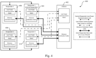
- Fig. 4 shows another illustrative embodiment of a vehicle access system 400.
- the system 400 comprises an initiator 402 and a plurality of responder nodes (i.e., responder devices) 404, 406, 408, 410 of the kind described above.
- the plurality of responder nodes 404, 406, 408, 410 may form part of a communication system of the kind set forth.
- the communication system may further include a controller (not shown), which may be implemented in the "Central Responder" 404.
- the initiator 402 is an example of an external communication device of the kind set forth.
- an example is shown of a system architecture that corresponds to the setup presented in fig. 3 , but now showing the data links between the different nodes.
- responder 3 does not open a "Distance Estimation Radio Link" to the initiator 402, because it was among the N-M responder devices with the lowest channel quality indicator.
- the following steps may be performed to enable ranging sessions in the vehicle access system shown in fig. 3 and fig. 4 .
- the different communication links are labeled as shown in fig. 4 .
- steps 4, 5 and 6 may occur at the same time as step 3, depending on when the channel information for a given responder becomes available. Accordingly, it may be possible to append the channel quality indicators to already existing data packets for distribution.
- the systems and methods described herein may at least partially be embodied by a computer program or a plurality of computer programs, which may exist in a variety of forms both active and inactive in a single computer system or across multiple computer systems.
- they may exist as software program(s) comprised of program instructions in source code, object code, executable code or other formats for performing some of the steps.
- Any of the above may be embodied on a computer-readable medium, which may include storage devices and signals, in compressed or uncompressed form.
- the term "computer” refers to any electronic device comprising a processor, such as a general-purpose central processing unit (CPU), a specific-purpose processor or a microcontroller.
- a computer is capable of receiving data (an input), of performing a sequence of predetermined operations thereupon, and of producing thereby a result in the form of information or signals (an output).
- the term "computer” will mean either a processor in particular or more generally a processor in association with an assemblage of interrelated elements contained within a single case or housing.
- processor or “processing unit” refers to a data processing circuit that may be a microprocessor, a co-processor, a microcontroller, a microcomputer, a central processing unit, a field programmable gate array (FPGA), a programmable logic circuit, and/or any circuit that manipulates signals (analog or digital) based on operational instructions that are stored in a memory.
- memory refers to a storage circuit or multiple storage circuits such as read-only memory, random access memory, volatile memory, non-volatile memory, static memory, dynamic memory, Flash memory, cache memory, and/or any circuit that stores digital information.
- a "computer-readable medium” or “storage medium” may be any means that can contain, store, communicate, propagate, or transport a computer program for use by or in connection with the instruction execution system, apparatus, or device.
- the computer-readable medium may be, for example but not limited to, an electronic, magnetic, optical, electromagnetic, infrared, or semiconductor system, apparatus, device, or propagation medium.
- the computer-readable medium may include the following: an electrical connection having one or more wires, a portable computer diskette, a random-access memory (RAM), a read-only memory (ROM), an erasable programmable read-only memory (EPROM or Flash memory), an optical fiber, a portable compact disc read-only memory (CDROM), a digital versatile disc (DVD), a Blu-ray disc (BD), and a memory card.
- RAM random-access memory
- ROM read-only memory
- EPROM or Flash memory erasable programmable read-only memory
- CDROM compact disc read-only memory
- DVD digital versatile disc
- BD Blu-ray disc
Landscapes
- Engineering & Computer Science (AREA)
- Computer Networks & Wireless Communication (AREA)
- Signal Processing (AREA)
- Radar, Positioning & Navigation (AREA)
- Remote Sensing (AREA)
- Physics & Mathematics (AREA)
- General Physics & Mathematics (AREA)
- Mobile Radio Communication Systems (AREA)
Claims (14)
- Kommunikationssystem, umfassend:eine Mehrzahl von Kommunikationsknoten (104, 106, 108, 110), die funktionell miteinander gekoppelt sind, wobei jeder der Kommunikationsknoten eine erste Hochfrequenzkommunikationseinheit, HF-Kommunikationseinheit, umfasst, die dazu ausgelegt ist, Entfernungsmessungssitzungen mit einer externen Kommunikationsvorrichtung durchzuführen;eine Steuerung (102), die dazu ausgelegt ist, eine logische Teilmenge der Kommunikationsknoten basierend auf einer Angabe einer Kanalqualität zwischen den Kommunikationsknoten und der externen Kommunikationsvorrichtung zu erstellen, wobei die Angabe der Kanalqualität unter Verwendung einer zweiten HF-Kommunikationseinheit erhalten wurde, die in jedem der Kommunikationsknoten umfasst ist;wobei die Steuerung ferner dazu ausgelegt ist, zu veranlassen, dass nur die Kommunikationsknoten, die in der logischen Teilmenge beinhaltet sind, die Entfernungsmessungssitzungen mit der externen Kommunikationsvorrichtung durchführen.
- System nach Anspruch 1, wobei die erste HF-Kommunikationseinheit eine Ultrabreitbandkommunikationseinheit, UWB-Kommunikationseinheit, oder eine Wi-Fi-Kommunikationseinheit ist.
- System nach Anspruch 1 oder 2, wobei die zweite HF-Kommunikationseinheit eine Niedrigleistungskommunikationseinheit, insbesondere eine Bluetooth-Niedrigleistungskommunikationseinheit, BLE-Kommunikationseinheit, eine Ultrahochfrequenzkommunikationseinheit, UHF-Kommunikationseinheit, oder eine Niederfrequenzkommunikationseinheit, NF-Kommunikationseinheit, ist.
- System nach einem der vorhergehenden Ansprüche, wobei einer der Kommunikationsknoten die Steuerung umfasst.
- System nach einem der vorhergehenden Ansprüche, wobei die Steuerung dazu ausgelegt ist, die logische Teilmenge zu erstellen, indem Kanalqualitätsindikatoren verglichen werden, die von allen Kommunikationsknoten bereitgestellt werden, und nur Kommunikationsknoten, die hohe Kanalqualitätsindikatoren bereitgestellt haben, in die logische Teilmenge einbezogen werden.
- System nach Anspruch 5, wobei die Kommunikationsknoten dazu ausgelegt sind, eine Normalisierungsfunktion auf die Kanalqualitätsindikatoren anzuwenden, bevor die Kanalqualitätsindikatoren für die Steuerung bereitgestellt werden.
- System nach Anspruch 5 oder 6, wobei, falls ein oder mehrere Kanalqualitätsindikatoren gleichwertig sind, die Steuerung dazu ausgelegt ist, alle Kommunikationsknoten, die die gleichwertigen Kanalqualitätsindikatoren bereitgestellt haben, in die logische Teilmenge einzubeziehen.
- System nach Anspruch 5 oder 6, wobei, falls ein oder mehrere Kanalqualitätsindikatoren gleichwertig sind, die Steuerung dazu ausgelegt ist, keinen der Kommunikationsknoten, die die gleichwertigen Kanalqualitätsindikatoren bereitgestellt haben, in die logische Teilmenge einzubeziehen.
- System nach Anspruch 5 oder 6, wobei, falls ein oder mehrere Kanalqualitätsindikatoren gleichwertig sind, die Steuerung dazu ausgelegt ist, zufällig ausgewählte Kommunikationsknoten, die die gleichwertigen Kanalqualitätsindikatoren bereitgestellt haben, in die logische Teilmenge einzubeziehen.
- System nach einem der vorhergehenden Ansprüche, wobei die Angabe der Kanalqualität auf mindestens einem der folgenden Parameter basiert:Empfangssignalstärkeindikator;Statistiken oder Parameter, die für den Kommunikationskanal charakteristisch sind;Entfernungsmessungsergebnisse, die unter Verwendung der zweiten HF-Kommunikationseinheit erhalten werden;Verbindungsstatus zwischen den Kommunikationsknoten und der externen Kommunikationsvorrichtung;Bitfehlerrate.
- System nach einem der vorhergehenden Ansprüche, wobei die Steuerung dazu ausgelegt ist, die logische Teilmenge unter Verwendung eines konfigurierbaren Parameters M zu erstellen, wobei M eine Anzahl von Kommunikationsknoten ist, die in die logische Teilmenge einbezogen werden sollen, und wobei M kleiner oder gleich der Gesamtzahl von Kommunikationsknoten in dem System ist.
- Verfahren (200) zum Betreiben eines Kommunikationssystems, wobei das System eine Mehrzahl von Kommunikationsknoten, die funktionell miteinander gekoppelt sind, und eine Steuerung umfasst, wobei jeder der Kommunikationsknoten eine erste Hochfrequenzkommunikationseinheit, HF-Kommunikationseinheit, umfasst, wobei das Verfahren Folgendes umfasst:Erstellen (202) einer logischen Teilmenge der Kommunikationsknoten durch die Steuerung basierend auf einer Angabe einer Kanalqualität zwischen den Kommunikationsknoten und einer externen Kommunikationsvorrichtung, wobei die Angabe der Kanalqualität unter Verwendung einer zweiten HF-Kommunikationseinheit erhalten wurde, die in jedem der Kommunikationsknoten umfasst ist;Veranlassen (204) durch die Steuerung, dass nur Kommunikationsknoten, die in der logischen Teilmenge beinhaltet sind, Entfernungsmessungssitzungen mit der externen Kommunikationsvorrichtung durchführen, wobei die Entfernungsmessungssitzungen durch die erste HF-Kommunikationseinheit durchgeführt werden.
- Verfahren nach Anspruch 12, wobei die erste HF-Kommunikationseinheit eine Ultrabreitbandkommunikationseinheit, UWB-Kommunikationseinheit, oder eine Wi-Fi-Kommunikationseinheit ist.
- Verfahren nach Anspruch 12 oder 13, wobei die zweite HF-Kommunikationseinheit eine Niedrigleistungskommunikationseinheit, insbesondere eine Bluetooth-Niedrigleistungskommunikationseinheit, BLE-Kommunikationseinheit, eine Ultrahochfrequenzkommunikationseinheit, UHF-Kommunikationseinheit, oder eine Niederfrequenzkommunikationseinheit, NF-Kommunikationseinheit, ist.
Priority Applications (2)
| Application Number | Priority Date | Filing Date | Title |
|---|---|---|---|
| EP21205829.1A EP4174804B1 (de) | 2021-11-01 | 2021-11-01 | Drahtloses ranging-kommunikationssystem und betriebsverfahren |
| US17/936,879 US12389240B2 (en) | 2021-11-01 | 2022-09-30 | Communication system and operating method |
Applications Claiming Priority (1)
| Application Number | Priority Date | Filing Date | Title |
|---|---|---|---|
| EP21205829.1A EP4174804B1 (de) | 2021-11-01 | 2021-11-01 | Drahtloses ranging-kommunikationssystem und betriebsverfahren |
Publications (2)
| Publication Number | Publication Date |
|---|---|
| EP4174804A1 EP4174804A1 (de) | 2023-05-03 |
| EP4174804B1 true EP4174804B1 (de) | 2025-05-28 |
Family
ID=78695478
Family Applications (1)
| Application Number | Title | Priority Date | Filing Date |
|---|---|---|---|
| EP21205829.1A Active EP4174804B1 (de) | 2021-11-01 | 2021-11-01 | Drahtloses ranging-kommunikationssystem und betriebsverfahren |
Country Status (2)
| Country | Link |
|---|---|
| US (1) | US12389240B2 (de) |
| EP (1) | EP4174804B1 (de) |
Families Citing this family (2)
| Publication number | Priority date | Publication date | Assignee | Title |
|---|---|---|---|---|
| EP4174804B1 (de) * | 2021-11-01 | 2025-05-28 | Nxp B.V. | Drahtloses ranging-kommunikationssystem und betriebsverfahren |
| WO2025144607A1 (en) * | 2023-12-29 | 2025-07-03 | Cisco Technology, Inc. | Channel selection in wireless networks for narrowband-assisted ultra-wideband signaling |
Citations (1)
| Publication number | Priority date | Publication date | Assignee | Title |
|---|---|---|---|---|
| US11212642B2 (en) * | 2017-02-10 | 2021-12-28 | Apple Inc. | Enhanced automotive passive entry |
Family Cites Families (14)
| Publication number | Priority date | Publication date | Assignee | Title |
|---|---|---|---|---|
| US10328898B2 (en) * | 2016-10-12 | 2019-06-25 | Denso International America, Inc. | Passive entry / passive start systems and methods for vehicles |
| KR101871052B1 (ko) | 2016-10-18 | 2018-06-25 | 조선대학교산학협력단 | 하이브리드 실내 측위 시스템 및 그 방법 |
| KR102578010B1 (ko) | 2017-11-30 | 2023-09-14 | 한국전자통신연구원 | Uwb 위치인식 시스템, 서버 및 이의 최적 앵커 선택 방법 |
| GB201720550D0 (en) * | 2017-12-08 | 2018-01-24 | Decawave Ltd | Ranging with simultaneous frames |
| JP7009328B2 (ja) * | 2018-03-22 | 2022-01-25 | 株式会社東海理化電機製作所 | 距離測定システム |
| US10573104B2 (en) * | 2018-06-29 | 2020-02-25 | Robert Bosch Gmbh | Ultra-wideband based vehicle access system and communication protocol for localization of a target device |
| CN108900974A (zh) | 2018-07-25 | 2018-11-27 | 山东精诚电子科技有限公司 | 基于2.4G RFID、UWB和LoRa人员调度通信定位终端及方法 |
| US10559149B1 (en) * | 2018-10-08 | 2020-02-11 | Nxp B.V. | Dynamic anchor pre-selection for ranging applications |
| US11026067B2 (en) * | 2019-01-11 | 2021-06-01 | Sensormatic Electronics, LLC | Power efficient ultra-wideband (UWB) tag for indoor positioning |
| US11635774B2 (en) | 2019-06-29 | 2023-04-25 | Intel Corporation | Dynamic anchor selection for swarm localization |
| EP3805792B1 (de) * | 2019-10-11 | 2025-03-19 | Nxp B.V. | Übertragung von nutzlast zwischen einer mobilen vorrichtung und mehreren ankervorrichtungen über eine abstandsmessfähige physikalische schichtkommunikation |
| US11740342B2 (en) | 2020-09-29 | 2023-08-29 | Nxp B.V. | Method and apparatus for selecting a ranging anchor based on characteristics of communication between a connection anchor and a mobile electronic device |
| US12267806B2 (en) * | 2021-09-03 | 2025-04-01 | Denso International America, Inc. | Distributed generation of real-time location |
| EP4174804B1 (de) * | 2021-11-01 | 2025-05-28 | Nxp B.V. | Drahtloses ranging-kommunikationssystem und betriebsverfahren |
-
2021
- 2021-11-01 EP EP21205829.1A patent/EP4174804B1/de active Active
-
2022
- 2022-09-30 US US17/936,879 patent/US12389240B2/en active Active
Patent Citations (1)
| Publication number | Priority date | Publication date | Assignee | Title |
|---|---|---|---|---|
| US11212642B2 (en) * | 2017-02-10 | 2021-12-28 | Apple Inc. | Enhanced automotive passive entry |
Also Published As
| Publication number | Publication date |
|---|---|
| US12389240B2 (en) | 2025-08-12 |
| EP4174804A1 (de) | 2023-05-03 |
| US20240129754A1 (en) | 2024-04-18 |
Similar Documents
| Publication | Publication Date | Title |
|---|---|---|
| US9622187B2 (en) | Real-time specific absorption rate implementation in wireless devices | |
| US20200236639A1 (en) | Method and apparatus for power autoscaling in a resource-constrained network | |
| US11711154B2 (en) | Method of reporting RSSI measurements in an unlicensed band and related apparatus | |
| Afifi et al. | Adaptive transmission-reception-sensing strategy for cognitive radios with full-duplex capabilities | |
| Yuan et al. | Coexistence performance of IEEE 802.15. 4 wireless sensor networks under IEEE 802.11 b/g interference | |
| EP4080781B1 (de) | Kommunikationsvorrichtung und betriebsverfahren | |
| EP4174804B1 (de) | Drahtloses ranging-kommunikationssystem und betriebsverfahren | |
| US10034300B2 (en) | Load based probe response scheduling | |
| US9380541B1 (en) | Managing specific absorption rate distribution to maximize transmit power of a wireless device | |
| CN119183642A (zh) | 用于无源终端发现的装置和方法 | |
| JP2020513710A (ja) | 起動無線機 | |
| WO2019157726A1 (zh) | 资源上报的方法、终端设备和网络设备 | |
| US20250142541A1 (en) | Wireless communication method and device | |
| Shao et al. | When lorawan meets csma: Trends, challenges, and opportunities | |
| EP3017623B1 (de) | Verfahren und vorrichtung zum umschalten einer kommunikation von einem ersten kanal zu einem zweiten kanal mit höherer frequenz | |
| CN118749213A (zh) | 无线通信的方法、终端设备和参考设备 | |
| WO2024151301A1 (en) | Use of narrowband signaling within ultra-wideband spectrum as basis to facilitate ultra-wideband ranging | |
| EP3975629A1 (de) | Zeitliche mittelung für spezifische absorptionsrate und stromstärke | |
| WO2011154651A3 (fr) | Procede et reseau de transmission de l'information entre une pluralite de stations radioelectriques | |
| CN106797280A (zh) | 一种数据传输方法、系统及终端 | |
| US20200022182A1 (en) | Media access control | |
| CN114040421A (zh) | 一种无线资源测量方法及装置 | |
| CN107113015B (zh) | 测试方法和计算机可读存储介质 | |
| CN106060861A (zh) | 非授权频段载波的评估方法及应用其的演进节点 | |
| KR101540141B1 (ko) | 근거리 무선통신을 이용한 테스트 시스템 및 그 테스트 방법 |
Legal Events
| Date | Code | Title | Description |
|---|---|---|---|
| PUAI | Public reference made under article 153(3) epc to a published international application that has entered the european phase |
Free format text: ORIGINAL CODE: 0009012 |
|
| STAA | Information on the status of an ep patent application or granted ep patent |
Free format text: STATUS: THE APPLICATION HAS BEEN PUBLISHED |
|
| AK | Designated contracting states |
Kind code of ref document: A1 Designated state(s): AL AT BE BG CH CY CZ DE DK EE ES FI FR GB GR HR HU IE IS IT LI LT LU LV MC MK MT NL NO PL PT RO RS SE SI SK SM TR |
|
| STAA | Information on the status of an ep patent application or granted ep patent |
Free format text: STATUS: REQUEST FOR EXAMINATION WAS MADE |
|
| 17P | Request for examination filed |
Effective date: 20231103 |
|
| RBV | Designated contracting states (corrected) |
Designated state(s): AL AT BE BG CH CY CZ DE DK EE ES FI FR GB GR HR HU IE IS IT LI LT LU LV MC MK MT NL NO PL PT RO RS SE SI SK SM TR |
|
| REG | Reference to a national code |
Ref country code: DE Ref legal event code: R079 Free format text: PREVIOUS MAIN CLASS: G07C0009000000 Ipc: H04W0084180000 Ref document number: 602021031381 Country of ref document: DE |
|
| GRAP | Despatch of communication of intention to grant a patent |
Free format text: ORIGINAL CODE: EPIDOSNIGR1 |
|
| STAA | Information on the status of an ep patent application or granted ep patent |
Free format text: STATUS: GRANT OF PATENT IS INTENDED |
|
| RIC1 | Information provided on ipc code assigned before grant |
Ipc: G07C 9/00 20200101ALN20250220BHEP Ipc: G01S 13/02 20060101ALN20250220BHEP Ipc: G01S 13/76 20060101ALI20250220BHEP Ipc: H04W 84/18 20090101AFI20250220BHEP |
|
| INTG | Intention to grant announced |
Effective date: 20250310 |
|
| GRAS | Grant fee paid |
Free format text: ORIGINAL CODE: EPIDOSNIGR3 |
|
| GRAA | (expected) grant |
Free format text: ORIGINAL CODE: 0009210 |
|
| STAA | Information on the status of an ep patent application or granted ep patent |
Free format text: STATUS: THE PATENT HAS BEEN GRANTED |
|
| AK | Designated contracting states |
Kind code of ref document: B1 Designated state(s): AL AT BE BG CH CY CZ DE DK EE ES FI FR GB GR HR HU IE IS IT LI LT LU LV MC MK MT NL NO PL PT RO RS SE SI SK SM TR |
|
| REG | Reference to a national code |
Ref country code: GB Ref legal event code: FG4D |
|
| REG | Reference to a national code |
Ref country code: CH Ref legal event code: EP |
|
| REG | Reference to a national code |
Ref country code: DE Ref legal event code: R096 Ref document number: 602021031381 Country of ref document: DE |
|
| REG | Reference to a national code |
Ref country code: IE Ref legal event code: FG4D |
|
| REG | Reference to a national code |
Ref country code: NL Ref legal event code: MP Effective date: 20250528 |
|
| PG25 | Lapsed in a contracting state [announced via postgrant information from national office to epo] |
Ref country code: FI Free format text: LAPSE BECAUSE OF FAILURE TO SUBMIT A TRANSLATION OF THE DESCRIPTION OR TO PAY THE FEE WITHIN THE PRESCRIBED TIME-LIMIT Effective date: 20250528 Ref country code: ES Free format text: LAPSE BECAUSE OF FAILURE TO SUBMIT A TRANSLATION OF THE DESCRIPTION OR TO PAY THE FEE WITHIN THE PRESCRIBED TIME-LIMIT Effective date: 20250528 |
|
| REG | Reference to a national code |
Ref country code: LT Ref legal event code: MG9D |
|
| PG25 | Lapsed in a contracting state [announced via postgrant information from national office to epo] |
Ref country code: NO Free format text: LAPSE BECAUSE OF FAILURE TO SUBMIT A TRANSLATION OF THE DESCRIPTION OR TO PAY THE FEE WITHIN THE PRESCRIBED TIME-LIMIT Effective date: 20250828 Ref country code: GR Free format text: LAPSE BECAUSE OF FAILURE TO SUBMIT A TRANSLATION OF THE DESCRIPTION OR TO PAY THE FEE WITHIN THE PRESCRIBED TIME-LIMIT Effective date: 20250829 |
|
| PG25 | Lapsed in a contracting state [announced via postgrant information from national office to epo] |
Ref country code: NL Free format text: LAPSE BECAUSE OF FAILURE TO SUBMIT A TRANSLATION OF THE DESCRIPTION OR TO PAY THE FEE WITHIN THE PRESCRIBED TIME-LIMIT Effective date: 20250528 Ref country code: PL Free format text: LAPSE BECAUSE OF FAILURE TO SUBMIT A TRANSLATION OF THE DESCRIPTION OR TO PAY THE FEE WITHIN THE PRESCRIBED TIME-LIMIT Effective date: 20250528 |
|
| PG25 | Lapsed in a contracting state [announced via postgrant information from national office to epo] |
Ref country code: BG Free format text: LAPSE BECAUSE OF FAILURE TO SUBMIT A TRANSLATION OF THE DESCRIPTION OR TO PAY THE FEE WITHIN THE PRESCRIBED TIME-LIMIT Effective date: 20250528 |
|
| PG25 | Lapsed in a contracting state [announced via postgrant information from national office to epo] |
Ref country code: HR Free format text: LAPSE BECAUSE OF FAILURE TO SUBMIT A TRANSLATION OF THE DESCRIPTION OR TO PAY THE FEE WITHIN THE PRESCRIBED TIME-LIMIT Effective date: 20250528 |
|
| PG25 | Lapsed in a contracting state [announced via postgrant information from national office to epo] |
Ref country code: RS Free format text: LAPSE BECAUSE OF FAILURE TO SUBMIT A TRANSLATION OF THE DESCRIPTION OR TO PAY THE FEE WITHIN THE PRESCRIBED TIME-LIMIT Effective date: 20250828 |
|
| PG25 | Lapsed in a contracting state [announced via postgrant information from national office to epo] |
Ref country code: IS Free format text: LAPSE BECAUSE OF FAILURE TO SUBMIT A TRANSLATION OF THE DESCRIPTION OR TO PAY THE FEE WITHIN THE PRESCRIBED TIME-LIMIT Effective date: 20250928 |
|
| PG25 | Lapsed in a contracting state [announced via postgrant information from national office to epo] |
Ref country code: LV Free format text: LAPSE BECAUSE OF FAILURE TO SUBMIT A TRANSLATION OF THE DESCRIPTION OR TO PAY THE FEE WITHIN THE PRESCRIBED TIME-LIMIT Effective date: 20250528 |
|
| REG | Reference to a national code |
Ref country code: AT Ref legal event code: MK05 Ref document number: 1799388 Country of ref document: AT Kind code of ref document: T Effective date: 20250528 |
|
| PGFP | Annual fee paid to national office [announced via postgrant information from national office to epo] |
Ref country code: DE Payment date: 20251022 Year of fee payment: 5 |
|
| PG25 | Lapsed in a contracting state [announced via postgrant information from national office to epo] |
Ref country code: SM Free format text: LAPSE BECAUSE OF FAILURE TO SUBMIT A TRANSLATION OF THE DESCRIPTION OR TO PAY THE FEE WITHIN THE PRESCRIBED TIME-LIMIT Effective date: 20250528 Ref country code: AT Free format text: LAPSE BECAUSE OF FAILURE TO SUBMIT A TRANSLATION OF THE DESCRIPTION OR TO PAY THE FEE WITHIN THE PRESCRIBED TIME-LIMIT Effective date: 20250528 Ref country code: DK Free format text: LAPSE BECAUSE OF FAILURE TO SUBMIT A TRANSLATION OF THE DESCRIPTION OR TO PAY THE FEE WITHIN THE PRESCRIBED TIME-LIMIT Effective date: 20250528 |
|
| PGFP | Annual fee paid to national office [announced via postgrant information from national office to epo] |
Ref country code: FR Payment date: 20251022 Year of fee payment: 5 |
|
| PG25 | Lapsed in a contracting state [announced via postgrant information from national office to epo] |
Ref country code: CZ Free format text: LAPSE BECAUSE OF FAILURE TO SUBMIT A TRANSLATION OF THE DESCRIPTION OR TO PAY THE FEE WITHIN THE PRESCRIBED TIME-LIMIT Effective date: 20250528 |
|
| PG25 | Lapsed in a contracting state [announced via postgrant information from national office to epo] |
Ref country code: EE Free format text: LAPSE BECAUSE OF FAILURE TO SUBMIT A TRANSLATION OF THE DESCRIPTION OR TO PAY THE FEE WITHIN THE PRESCRIBED TIME-LIMIT Effective date: 20250528 |
|
| PG25 | Lapsed in a contracting state [announced via postgrant information from national office to epo] |
Ref country code: SK Free format text: LAPSE BECAUSE OF FAILURE TO SUBMIT A TRANSLATION OF THE DESCRIPTION OR TO PAY THE FEE WITHIN THE PRESCRIBED TIME-LIMIT Effective date: 20250528 |
|
| PG25 | Lapsed in a contracting state [announced via postgrant information from national office to epo] |
Ref country code: IT Free format text: LAPSE BECAUSE OF FAILURE TO SUBMIT A TRANSLATION OF THE DESCRIPTION OR TO PAY THE FEE WITHIN THE PRESCRIBED TIME-LIMIT Effective date: 20250528 |
|
| REG | Reference to a national code |
Ref country code: DE Ref legal event code: R097 Ref document number: 602021031381 Country of ref document: DE |
|
| PG25 | Lapsed in a contracting state [announced via postgrant information from national office to epo] |
Ref country code: RO Free format text: LAPSE BECAUSE OF FAILURE TO SUBMIT A TRANSLATION OF THE DESCRIPTION OR TO PAY THE FEE WITHIN THE PRESCRIBED TIME-LIMIT Effective date: 20250528 |
|
| PLBE | No opposition filed within time limit |
Free format text: ORIGINAL CODE: 0009261 |
|
| STAA | Information on the status of an ep patent application or granted ep patent |
Free format text: STATUS: NO OPPOSITION FILED WITHIN TIME LIMIT |
|
| REG | Reference to a national code |
Ref country code: CH Ref legal event code: L10 Free format text: ST27 STATUS EVENT CODE: U-0-0-L10-L00 (AS PROVIDED BY THE NATIONAL OFFICE) Effective date: 20260409 |