EP4174588A1 - Time measurement device, fluorescence lifetime measurement device, and time measurement method - Google Patents
Time measurement device, fluorescence lifetime measurement device, and time measurement method Download PDFInfo
- Publication number
- EP4174588A1 EP4174588A1 EP21854514.3A EP21854514A EP4174588A1 EP 4174588 A1 EP4174588 A1 EP 4174588A1 EP 21854514 A EP21854514 A EP 21854514A EP 4174588 A1 EP4174588 A1 EP 4174588A1
- Authority
- EP
- European Patent Office
- Prior art keywords
- time
- signal
- measurement
- gate
- detection signal
- Prior art date
- Legal status (The legal status is an assumption and is not a legal conclusion. Google has not performed a legal analysis and makes no representation as to the accuracy of the status listed.)
- Granted
Links
Images









Classifications
-
- G—PHYSICS
- G04—HOROLOGY
- G04F—TIME-INTERVAL MEASURING
- G04F10/00—Apparatus for measuring unknown time intervals by electric means
-
- G—PHYSICS
- G01—MEASURING; TESTING
- G01N—INVESTIGATING OR ANALYSING MATERIALS BY DETERMINING THEIR CHEMICAL OR PHYSICAL PROPERTIES
- G01N21/00—Investigating or analysing materials by the use of optical means, i.e. using sub-millimetre waves, infrared, visible or ultraviolet light
- G01N21/62—Systems in which the material investigated is excited whereby it emits light or causes a change in wavelength of the incident light
- G01N21/63—Systems in which the material investigated is excited whereby it emits light or causes a change in wavelength of the incident light optically excited
- G01N21/64—Fluorescence; Phosphorescence
- G01N21/6408—Fluorescence; Phosphorescence with measurement of decay time, time resolved fluorescence
-
- G—PHYSICS
- G01—MEASURING; TESTING
- G01J—MEASUREMENT OF INTENSITY, VELOCITY, SPECTRAL CONTENT, POLARISATION, PHASE OR PULSE CHARACTERISTICS OF INFRARED, VISIBLE OR ULTRAVIOLET LIGHT; COLORIMETRY; RADIATION PYROMETRY
- G01J3/00—Spectrometry; Spectrophotometry; Monochromators; Measuring colours
- G01J3/28—Investigating the spectrum
- G01J3/2823—Imaging spectrometer
-
- G—PHYSICS
- G01—MEASURING; TESTING
- G01J—MEASUREMENT OF INTENSITY, VELOCITY, SPECTRAL CONTENT, POLARISATION, PHASE OR PULSE CHARACTERISTICS OF INFRARED, VISIBLE OR ULTRAVIOLET LIGHT; COLORIMETRY; RADIATION PYROMETRY
- G01J3/00—Spectrometry; Spectrophotometry; Monochromators; Measuring colours
- G01J3/28—Investigating the spectrum
- G01J3/44—Raman spectrometry; Scattering spectrometry ; Fluorescence spectrometry
- G01J3/4406—Fluorescence spectrometry
-
- G—PHYSICS
- G01—MEASURING; TESTING
- G01N—INVESTIGATING OR ANALYSING MATERIALS BY DETERMINING THEIR CHEMICAL OR PHYSICAL PROPERTIES
- G01N21/00—Investigating or analysing materials by the use of optical means, i.e. using sub-millimetre waves, infrared, visible or ultraviolet light
- G01N21/62—Systems in which the material investigated is excited whereby it emits light or causes a change in wavelength of the incident light
- G01N21/63—Systems in which the material investigated is excited whereby it emits light or causes a change in wavelength of the incident light optically excited
- G01N21/64—Fluorescence; Phosphorescence
-
- G—PHYSICS
- G01—MEASURING; TESTING
- G01N—INVESTIGATING OR ANALYSING MATERIALS BY DETERMINING THEIR CHEMICAL OR PHYSICAL PROPERTIES
- G01N21/00—Investigating or analysing materials by the use of optical means, i.e. using sub-millimetre waves, infrared, visible or ultraviolet light
- G01N21/62—Systems in which the material investigated is excited whereby it emits light or causes a change in wavelength of the incident light
- G01N21/63—Systems in which the material investigated is excited whereby it emits light or causes a change in wavelength of the incident light optically excited
- G01N21/64—Fluorescence; Phosphorescence
- G01N21/6428—Measuring fluorescence of fluorescent products of reactions or of fluorochrome labelled reactive substances, e.g. measuring quenching effects, using measuring "optrodes"
-
- G—PHYSICS
- G04—HOROLOGY
- G04F—TIME-INTERVAL MEASURING
- G04F10/00—Apparatus for measuring unknown time intervals by electric means
- G04F10/005—Time-to-digital converters [TDC]
-
- G—PHYSICS
- G01—MEASURING; TESTING
- G01N—INVESTIGATING OR ANALYSING MATERIALS BY DETERMINING THEIR CHEMICAL OR PHYSICAL PROPERTIES
- G01N21/00—Investigating or analysing materials by the use of optical means, i.e. using sub-millimetre waves, infrared, visible or ultraviolet light
- G01N21/17—Systems in which incident light is modified in accordance with the properties of the material investigated
- G01N21/47—Scattering, i.e. diffuse reflection
- G01N21/4795—Scattering, i.e. diffuse reflection spatially resolved investigating of object in scattering medium
- G01N2021/4797—Scattering, i.e. diffuse reflection spatially resolved investigating of object in scattering medium time resolved, e.g. analysis of ballistic photons
Definitions
- One aspect of the present invention relates to a time measurement apparatus, a fluorescence lifetime measurement apparatus, and a time measurement method.
- TCSPC time correlated single photon counting
- Patent Literature 1 German Patent Application No. 102008004549
- a dead time in which a time cannot be measured again for a certain period of time is set. Due to the generation of the dead time, in a case where a phenomenon such as fluorescence is detected and time measurement related to the phenomenon (for example, fluorescence lifetime measurement) is performed, there is a concern that a time waveform for the phenomenon cannot be appropriately acquired. That is, since a time waveform cannot be acquired during a dead time, an accurate time waveform for the phenomenon may not be acquired even when time waveforms that could be obtained are synthesized.
- One aspect of the present invention has been made in view of the above circumstances, and relates to a time measurement apparatus, a fluorescence lifetime measurement apparatus, and a time measurement method which are capable of appropriately acquiring a time waveform related to a phenomenon.
- a time measurement apparatus includes a first time measurement instrument configured to receive an input of a detection signal, which is a phenomenon detected and output by a detector, and output a measurement signal corresponding to a time associated with the detection signal, a gate unit configured to be provided between the detector and the first time measurement instrument and set to be in a first state where the detection signal is transmitted in a direction of the first time measurement instrument, or a second state where the detection signal is not transmitted in a direction of the first time measurement instrument, a setting unit configured to set a gate dead time during which the gate unit is set to be in the second state in the gate unit, and a derivation unit configured to derive and output time information related to the detection signal based on the measurement signal output from the first time measurement instrument, in which the setting unit sets a time, which is an integral multiple of a repetition period of the phenomenon detected by the detector and is longer than a dead time of the first time measurement instrument itself, in the gate unit as the gate dead time.
- switching is made between a first state where a detection signal is input to the first time measurement instrument that outputs a measurement signal corresponding to a time associated with the detection signal and a second state where the detection signal is not input.
- a gate dead time that is an integral multiple of a repetition period of the phenomenon and is longer than a dead time of the first time measurement instrument itself is set in the gate unit, and the first time measurement instrument is set to be in the second state described above during the gate dead time.
- a gate dead time that is an integral multiple of the repetition period of the phenomenon is set in the gate unit, and thus a time waveform in time information derived based on the measurement signal output from the first time measurement instrument is equivalent to a waveform that is temporally continuous before and after the dead time (non-measurement state).
- the gate dead time set in the gate unit is longer than the dead time of the first time measurement instrument itself, the dead time of the first time measurement instrument does not occur in spite of a measurement state where a detection signal is input to the first time measurement instrument, and thus it is possible to appropriately secure continuity of a time waveform before and after the gate dead time described above.
- the time measurement apparatus may further include a delay generation circuit, in which the setting unit may set a delay amount that is an integral multiple of the repetition period in the delay generation circuit, the delay generation circuit may receive an input of the detection signal that has passed through the gate unit set to be in the first state, and may output a delay signal delayed by the delay amount set by the setting unit with respect to the detection signal to the gate unit, and the gate unit may be set to be in the first state to transmit the detection signal, may be set to be in the second state until receiving an input of the delay signal, and may receive the input of the delay signal, and then may be set to be in the first state until a new detection signal is input.
- the setting unit may set a delay amount that is an integral multiple of the repetition period in the delay generation circuit
- the delay generation circuit may receive an input of the detection signal that has passed through the gate unit set to be in the first state, and may output a delay signal delayed by the delay amount set by the setting unit with respect to the detection signal to the gate unit
- the gate unit may be set to be in the
- the first time measurement instrument may include a time-amplitude converter that outputs the measurement signal corresponding to a time associated with the detection signal as an analog signal, and a converter that converts the analog signal output from the time-amplitude converter into a digital signal and outputs the digital signal.
- a time-amplitude converter that outputs a measurement signal as an analog signal
- the converter it is possible to increase a time resolution in the measurement of a phenomenon as compared with a case where, for example, a time-digital converter is used.
- the time measurement apparatus may further include a counter configured to output a count signal in accordance with a clock signal, in which the first time measurement instrument may receive inputs of the detection signal and the clock signal and output the measurement signal corresponding to a time between the detection signal and the clock signal, and the derivation unit may derive and output the time information based on the count signal output from the counter and the measurement signal output from the first time measurement instrument.
- the counter operating in synchronization with a clock signal outputs a count signal so that rough time measurement (low time resolution and long time measurement) depending on the clock frequency is performed, and the first time-amplitude converter outputs a measurement signal corresponding to a time between a detection signal and the clock signal so that fine time measurement (high time resolution and short time measurement) for compensating for the measurement roughness of the counter is performed.
- Final time information is derived by combining these time measurement results, and thus it is possible to realize a high time resolution and long time measurement.
- a fluorescence lifetime measurement apparatus is a fluorescence lifetime measurement apparatus that measures a lifetime of fluorescence emitted from a measurement target, the fluorescence lifetime measurement apparatus including a light source configured to generate light, the detector configured to detect the fluorescence from the measurement target irradiated with the light from the light source and output the detection signal, the time measurement apparatus configured to output time information related to the detection signal, and an arithmetic operation unit configured to derive a fluorescence lifetime of the measurement target based on the time information.
- the fluorescence lifetime measurement apparatus may further include a signal generation unit configured to generate a pulse signal for controlling output of light from the light source, in which the signal generation unit may output a setting signal indicating a repetition period of the fluorescence, which is synchronized with the pulse signal, to the setting unit.
- the setting signal indicating the repetition period of the fluorescence, which is synchronized with the pulse signal is output from the signal generation unit that generates the pulse signal, and thus the setting unit can appropriately set a gate dead time that is an integral multiple of a fluorescence repetition period in the gate unit.
- the arithmetic operation unit may output a setting signal indicating a repetition period of the fluorescence to the setting unit.
- the setting signal indicating the repetition period of the fluorescence is output from the arithmetic operation unit, and thus the setting unit can appropriately set a gate dead time that is an integral multiple of a fluorescence repetition period in the gate unit.
- the fluorescence lifetime measurement apparatus may further include a signal generation unit configured to generate a pulse signal for controlling output of light from the light source, in which the signal generation unit may output a synchronization signal synchronized with the pulse signal, the time measurement apparatus may further include a second time measurement apparatus that outputs a signal corresponding to the synchronization signal, and the derivation unit may derive the time information based on the signal corresponding to the synchronization signal.
- a time measurement method is a time measurement method executed by a time measurement apparatus, the time measurement method including setting a first dead time during which a detection signal, which is a phenomenon detected and output by a detector, is not input to a time measurement instrument to an integral multiple of a repetition period of the phenomenon, and deriving and outputting time information related to the detection signal based on the detection signal output from the time measurement instrument, in which the first dead time may be longer than a second dead time of the time measurement instrument itself.
- FIG. 1 is a diagram schematically illustrating a fluorescence lifetime measurement apparatus 1 according to the present embodiment.
- the fluorescence lifetime measurement apparatus 1 is a apparatus that measures the lifetime of fluorescence emitted from a sample S (measurement target).
- Fluorescence spectra of organic materials and fluorescence probes are important parameters for controlling and evaluating the functions and characteristics of samples, such as a peak wavelength and fluorescence intensity.
- fluorescence spectra acquire temporally integrated information, and thus in a case where a sample contains a plurality of substances or reaction systems, only the integrated information can be obtained.
- fluorescence lifetime measurement for measuring a time required for the sample to return to a ground state after being photoexcited by pulsed light in a time domain of sub-nanoseconds to milliseconds is effective.
- a fluorescence detection timing is derived by a time measurement apparatus 10 to be described below, the frequency distribution of the detection timing is obtained by detecting fluorescence a plurality of times, and the fluorescence lifetime of a sample S is estimated based on the frequency distribution.
- the fluorescence lifetime measurement apparatus 1 is configured to include a pulse generator 2 (signal generation unit), a light source 3, a detector 4, a computer 5 (arithmetic operation unit), a display apparatus 6, an input apparatus 7, and a time measurement apparatus 10.
- a pulse generator 2 signal generation unit
- a light source 3 for detecting light
- a detector 4 for detecting light
- a computer 5 for converting digital signals to digital signals
- a display apparatus 6 for a light source
- an input apparatus 7 a time measurement apparatus 10.
- a clock generation circuit 9 see FIG. 2 , which will be described later, in the configuration of the fluorescence lifetime measurement apparatus 1 is not illustrated.
- the pulse generator 2 generates a pulse signal for controlling the output of light from the light source 3, and outputs the pulse signal to the light source 3.
- the pulse generator 2 generates a pulse signal based on an instruction given from the computer 5. More specifically, the pulse generator 2 receives a setting signal indicating a fluorescence repetition period from the computer 5 and generates a pulse signal according to the setting signal.
- the light source 3 outputs excitation light emitted to the sample S based on the pulse signals output from the pulse generator 2. That is, the light source 3 irradiates the sample S with generated light.
- a light emitting diode (LED) light source a laser light source, a super luminescent diode (SLD) light source, a lamp-based light source, or the like can be used.
- the intensity of the excitation light may be set, for example, to the extent that one photon is emitted when the sample S is irradiated with the excitation light. Fluorescence corresponding to the excitation light is output from the sample S irradiated with the excitation light.
- the detector 4 detects fluorescence from the sample S irradiated with light emitted from the light source 3, and outputs a detection signal to a measurement gate 11 (details will be described later) of the time measurement apparatus 10.
- a photomultiplier tube an avalanche photodiode, a hybrid photo detector (HPD), a superconductive single photon detector (SSPD), or the like can be used.
- the computer 5 derives fluorescence lifetime based on the measurement results output from the time measurement apparatus 10 (in more detail, the control unit 14). Specifically, the computer 5 derives the frequency distribution of a fluorescence detection timing from time information of fluorescence (fluorescence detection timing) included in the measurement results, and obtains the fluorescence lifetime of the sample S from the frequency distribution. The computer 5 also outputs a setting signal indicating a repetition period of fluorescence to the pulse generator 2 and the control unit 14.
- the computer 5 is constituted by an arithmetic operation unit such as a CPU and a storage unit such as a RAM or a flash memory. Note that the computer 5 may take charge of the function of the control unit 14 of the time measurement apparatus 10.
- the display apparatus 6 is a display electrically coupled to the computer 5, and displays analysis results for the fluorescence lifetime of the sample S described above.
- the input apparatus 7 is a keyboard, a mouse, or the like, and can input and set analysis conditions and measurement conditions for the fluorescence lifetime.
- the time measurement apparatus 10 is a time measurement apparatus that calculates a time from when a first trigger signal is input to when a second trigger signal is input as a measurement time.
- the time measurement apparatus 10 can be applied to various apparatuses and systems that derive a difference in input timing between two signals (the first trigger signal and the second trigger signal) input at different timings from the two signals.
- the time measurement apparatus 10 is applied to the fluorescence lifetime measurement apparatus 1 that measures the lifetime of fluorescence emitted from the sample S.
- the time measurement apparatus 10 includes a measurement gate 11 (first switching unit) and a time-analog-converter (TAC) circuit 12 (time-amplitude converter) and a TAC control unit 13 (converter) that constitute a first time measurement instrument, a control unit 14 (setting unit, derivation unit), and a delay generation circuit 30.
- TAC time-analog-converter
- the TAC circuit 12 is a circuit of a time-amplitude converter circuit that outputs a time difference between the input of the first trigger signal and the input of the second trigger signal as an analog signal (amplitude).
- the TAC circuit 12 is configured to be able to measure, for example, a time of 10 ns. Specifically, the TAC circuit 12 outputs a detection signal, which is output by the detector 4 detecting fluorescence (phenomenon), as a first trigger signal, outputs a clock signal output from the clock generation circuit 9 (see FIG. 2 ) as a second trigger signal, and outputs an analog signal (amplitude) corresponding to a time between the detection signal and the clock signal as a measurement signal to the TAC control unit 13.
- the TAC circuit 12 receives inputs of the detection signal, which is output by the detector 4 detecting fluorescence (phenomenon), and the clock signal, and outputs the measurement signal corresponding to the time (time corresponding to the detection signal) between the detection signal and the clock signal.
- the TAC circuit 12 receives the detection signal input through the measurement gate 11.
- the TAC control unit 13 is an AD converter that converts the analog signal (amplitude), which is the measurement signal output from the TAC circuit 12, into a digital signal and outputs the digital signal.
- the TAC control unit 13 outputs the digital signal after AD conversion to the control unit 14 as a measurement signal.
- the measurement gate 11 receives an input of the detection signal, which is the first trigger signal, from the detector 4 and outputs the detection signal to the TAC circuit 12.
- the measurement gate 11 is provided between the detector 4 and the TAC circuit 12 and is set to be in a first state where the detection signal is transmitted in the direction of the TAC circuit 12 or a second state where the detection signal is not transmitted in the direction of the TAC circuit 12. That is, the measurement gate 11 is set to be in any one of the first state or the second state at all times.
- a dead time (gate dead time) is set in the measurement gate 11.
- the dead time here means a time during which the measurement gate 11 is set to be in a state where the detection signal is not transmitted in the direction of the TAC circuit 12, that is, the above-described second state.
- the gate dead time is set by the control unit 14 (setting unit) through the delay generation circuit 30, and is a time which is an integral multiple of a repetition period of a phenomenon (for example, fluorescence detected by the detector 4).
- the gate dead time set by the control unit 14 is longer than the dead time of the TAC circuit 12 itself.
- the dead time of the TAC circuit 12 itself is a time during which the TAC circuit 12 cannot measure a time again for a certain period of time after measuring the time.
- the measurement gate 11 receives a delay signal from the delay generation circuit 30, and is switched between the above-described first state and second state based on the delay signal. That is, the measurement gate 11 is set to be in the first state to transmit the detection signal and is then set to be in the second state until the delay signal is input. After the measurement gate 11 receives the input of the delay signal, the measurement gate 11 is set to be in the first state until a new detection signal is input.
- the delay signal is a signal delayed by a delay amount that is an integral multiple of a fluorescence repetition period (details will be described later). For this reason, the measurement gate 11 is set to be in the second state until the delay signal is input after the detection signal is transmitted, and thus a gate dead time being the second state can be appropriately set to an integral multiple of a fluorescence repetition period.
- the control unit 14 function as a setting unit that sets a gate dead time during which the measurement gate 11 is set to be in the second state, in the measurement gate 11 and a derivation unit that derives and outputs time information related to a detection signal based on the measurement signal output from the TAC control unit 13.
- the control unit 14 sets a time, which is a time being an integral multiple of a repetition period of fluorescence detected by the detector 4 and is longer than the dead time of the TAC circuit 12 itself, in the measurement gate 11 as a gate dead time.
- the control unit 14 sets the gate dead time in the measurement gate 11 via the delay generation circuit 30.
- the control unit 14 performs the delay control of the delay generation circuit 30 based on a setting signal (a signal indicating a fluorescence repetition period) which is input from the computer 5. That is, the control unit 14 sets a delay amount, which is an integral multiple of the repetition period, in the delay generation circuit 30 in advance based on the setting signal.
- the delay generation circuit 30 outputs a delay signal delayed by the set delay amount to the measurement gate 11.
- the delay generation circuit 30 is configured such that a detection signal having passed through the measurement gate 11 set to be in the first state is input (the detection signal is input similarly to the TAC circuit 12), and outputs the delay signal delayed by the delay amount set by the control unit 14 for the detection signal to the measurement gate 11 when receiving the input of the detection signal.
- the measurement gate 11 is set to be in the second state (the state of the gate dead time) until the measurement gate 11 receives an input of the delay signal after transmitting the detection signal.
- the gate dead time of the measurement gate 11 can be set to an integral multiple of a fluorescence repetition period.
- the control unit 14 derives and outputs time information related on a detection signal detected by the detector 4, based on a count signal output from the digital counter 20 (see FIG. 2 ) and a measurement signal output from the TAC circuit 12 and converted into a digital signal by the TAC control unit 13.
- the digital counter 20 is a counter to which a detection signal from the detector 4 and a clock signal from the clock generation circuit 9 are input.
- the digital counter 20 operates in synchronization with the clock signal and outputs the count signal to the control unit 14 in accordance with the clock signal (by counting the clock signal).
- the digital counter 20 can perform long-time measurement for a detection signal, it is difficult to increase a time resolution.
- the control unit 14 combines a time measurement result of the digital counter 20 and a time measurement result of the TAC circuit 12 with a high time resolution to achieve high time resolution and long-time measurement of time information related to the detection signal.
- FIGS. 3 and 4 are diagrams illustrating the derivation of the time information described above.
- the horizontal axis indicates a time axis.
- the digital counter 20 counts clock signals and outputs a count signal.
- FIG. 3 illustrates an example in which the digital counter 20 outputs count signals indicating 23, 24, 25, 26, 27, and 28.
- the digital counter 20 operates in synchronization with a clock signal.
- the TAC circuit 12 measures a time difference T between the input of a detection signal TRG1 from the detector 4 and the input of a clock signal TRG2 immediately after the detection signal TRG1.
- TRG1 the input of a detection signal
- TRG2 the input of a clock signal
- a voltage (amplitude) is started to increase in response to the detection signal TRG1 from a timing (time 11) when the detection signal TRG1 is input, and a voltage (amplitude) becomes constant in response to the clock signal TRG2 from a timing (time t2) when the clock signal TRG2 is input.
- the control unit 14 derives time information indicating a time until a detection signal is input to the TAC circuit 12 by subtracting a time indicated by the measurement signal from a time corresponding to a count value indicated by the count signal. That is, in the example illustrated in FIG. 3 , the control unit 14 derives time information (23-T) indicating a time until the detection signal TRG1 is input to the TAC circuit 12 by subtracting a time difference T, which is time information indicated by the measurement signal, from 23 which is a time corresponding to the count value indicated by the count signal.
- time information can be derived by correspondence of the clock signal input to the digital counter 20 and the clock signal input to the TAC circuit 12 (the count value indicated by the clock signal input to the TAC circuit 12 is uniquely determined).
- the control unit 14 outputs the derived time information (measurement result) to the computer 5.
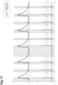
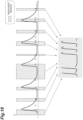
- FIGS. 5 to 12 are diagrams illustrating acquisition of a fluorescence time waveform in the fluorescence lifetime measurement apparatus 1 according to the present embodiment.
- FIGS. 13 to 18 are diagrams illustrating acquisition of a fluorescence time waveform in the fluorescence lifetime measurement apparatus 1 according to a comparative example.
- the horizontal axis represents a time.
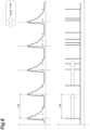
- the number of frequencies of a pulse signal output from the pulse generator 2 is 1 MHz, and a fluorescence repetition period of 1 ⁇ s. It is assumed that fluorescence emission occurs along a curve illustrated in the upper part of FIG. 5 , and that a plurality of squares illustrated in the upper part of FIG. 5 indicate the generation of photons associated with fluorescence (hereinafter, the same applies to FIG. 6 and the subsequent drawings).
- detection signals output from the detector 4 are illustrated. As illustrated in the lower part of FIG. 5 , a detection signal corresponding to each photon is output from the detector 4 at a timing when each photon is detected due to the generation of the photons.
- a dead time during which a time cannot be measured again for a certain period of time occurs.
- a fluorescence lifetime measurement apparatus for example, a fluorescence lifetime measurement apparatus according to a comparative example to be described later
- a time that is an integral multiple of a fluorescence repetition period (and is longer than the dead time of the TAC circuit 12 itself) is set in the measurement gate 11 as a gate dead time.
- a gate dead time that is one time the fluorescence repetition period (the same as a fluorescence repetition period) is set in the measurement gate 11 is indicated. Note that a "dead time" in each of FIGS. 6 to 10 indicates a gate dead time.
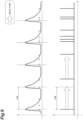
- a gate dead time (first gate dead time) illustrated in FIG. 6 occurs after a first photon is measured, a signal during the first gate dead time cannot be acquired, and thus a detection signal that actually passes through the measurement gate 11 is as illustrated in a lower part of FIG. 7 in consideration of the first gate dead time.
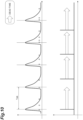
- a gate dead time (second gate dead time) illustrated in FIG. 8 occurs again. Since a signal cannot be acquired even during the second gate dead time, a detection signal that actually passes through the measurement gate 11 is as illustrated in a lower part of FIG. 9 in consideration of the second gate dead time. In this manner, when a gate dead time occurring after photon measurement is repeated, a detection signal that actually passes through the measurement gate 11 is as illustrated in FIG. 10 .
- a time during which time measurement can be performed by such a fluorescence lifetime measurement apparatus is a time indicated by a "measured region" in FIG. 11 .
- Such a state of time is a measurement standby state where measurement can be performed whenever photons are input.
- the measurement standby state is a time during which the fluorescence lifetime measurement apparatus 1 actually performs time measurement. Then, as illustrated in FIG. 12 , when the "measured regions" are arranged in order of occurrence on the time axis, it can be understood that the original fluorescence emission curve appears.
- the gate dead time is set to an integral multiple (one time in this case) of a fluorescence repetition period, and time waveforms before and after each dead time being synthesized are equivalent to a waveform of a temporally continuous fluorescence curve.
- a configuration in which a gate dead time is not set (a configuration according to a comparative example) will be described with reference to FIGS. 13 to 18 .
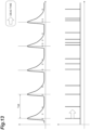
- a "dead time" in each of FIGS. 13 to 16 means a dead time of the TAC circuit itself instead of a gate dead time.
- a fluorescence repetition period is set to 1 ⁇ s, and a gate dead time is not set. Since a gate dead time is not set, dead time after photons are detected is only the dead time of the TAC circuit itself (which is a dead time shorter than the above-described gate dead time) as illustrated in the lower part of FIG. 13 .
- a waveform illustrated in FIG. 18 is formed.
- the waveform is different from the above-described waveform illustrated in FIG. 12 and does not match the waveform of the original fluorescence curve at all. In this manner, in a configuration in which a dead time that is an integral multiple of a fluorescence repetition period is not set, it is not possible to perform measurement (continuous acquisition of fluorescence waveforms) as if continuous measurement has been performed.
- the time measurement apparatus 10 includes the TAC circuit 12 that receives an input of a detection signal, which is a phenomenon detected and output by the detector 4, and outputs a measurement signal corresponding to a time associated with the detection signal, the measurement gate 11 which is provided between the detector 4 and the TAC circuit 12 and is set to be in a first state where the detection signal is transmitted in the direction of the TAC circuit 12 or a second state where the detection signal is not transmitted in the direction of the TAC circuit 12, the control unit 14 that functions as a setting unit for setting a gate dead time, which is a time during which the measurement gate 11 is set to be in the second state, in the measurement gate 11, and the control unit 14 that functions as a derivation unit for deriving and outputting time information related to the detection signal based on the measurement signal output from the TAC circuit 12.
- the control unit 14 functioning as a setting unit sets a time, which is an integral multiple of a repetition period of fluorescence detected by the detector 4 and is longer than a dead time of the TAC circuit 12 itself
- switching is made between a first state where a detection signal is input to the TAC circuit 12 that outputs a measurement signal corresponding to a time associated with the detection signal and a second state where the detection signal is not input.
- a gate dead time that is an integral multiple of a repetition period of fluorescence and is longer than a dead time of the TAC circuit 12 itself is set in the measurement gate 11, and the measurement gate 11 is set to be in the second state described above during the gate dead time.
- a gate dead time that is an integral multiple of the repetition period of fluorescence is set in the measurement gate 11, and thus a time waveform in time information derived based on the measurement signal output from the TAC circuit 12 is equivalent to a waveform that is temporally continuous before and after the dead time (non-measurement state).
- the gate dead time set in the measurement gate 11 is longer than the dead time of the TAC circuit 12 itself, the dead time of the TAC circuit 12 itself does not occur in spite of a measurement state where a detection signal is input to the TAC circuit 12, and thus it is possible to appropriately secure continuity of a time waveform before and after the gate dead time described above.
- the time measurement apparatus 10 may further include the delay generation circuit 30, the control unit 14 functioning as a setting unit may set a delay amount that is an integral multiple of a repetition period in the delay generation circuit 30, the delay generation circuit 30 may receive an input of a detection signal having passed through the measurement gate 11 set to be in a first state and output a delay signal delayed by the delay amount set by the control unit 14 functioning as a setting unit with respect to the detection signal to the measurement gate 11, and the measurement gate 11 may be set to be in the first state to transmit the detection signal, set to be in a second state until an input of the delay signal is received, receive the input of the delay signal, and then set to be in the first state until a new detection signal is input.
- a gate dead time that is an integral multiple of a repetition period can be reliably set in the measurement gate 11.
- the first time measurement instrument may include the TAC circuit 12 that outputs a measurement signal corresponding to a time associated with a detection signal as an analog signal, and the TAC control unit 13 that converts the analog signal output from the TAC circuit 12 into a digital signal and outputs it.
- the TAC circuit 12 which outputs a measurement signal as an analog signal
- the TAC control unit 13 it is possible to increase a time resolution in the measurement of a phenomenon as compared with a case where, for example, a time-digital converter is used.
- the time measurement apparatus 10 may further include the digital counter 20 that outputs a count signal in accordance with a clock signal, the TAC circuit 12 may receive inputs of a detection signal and the clock signal and output a measurement signal corresponding to a time between the detection signal and the clock signal, and the control unit 14 functioning as a derivation unit may derive and output time information based on a count signal output from the digital counter 20 and the measurement signal output from the TAC circuit 12.
- the digital counter 20 which operates in synchronization with the clock signal, outputs the count signal to perform rough time measurement (a low time resolution and long-time measurement) depending on the frequency of a clock, and the TAC circuit 12 outputs a measurement signal corresponding to a time between the detection signal and the clock signal to perform fine time measurement (a high time resolution and short-time measurement) that compensates for the measurement roughness of the digital counter 20.
- rough time measurement a low time resolution and long-time measurement
- the TAC circuit 12 outputs a measurement signal corresponding to a time between the detection signal and the clock signal to perform fine time measurement (a high time resolution and short-time measurement) that compensates for the measurement roughness of the digital counter 20.
- a fluorescence lifetime measurement apparatus 1 which is a fluorescence lifetime measurement apparatus that measures the lifetime of fluorescence emitted from a sample S, includes the light source 3 that irradiates the sample S with generated light, the detector 4 that detects fluorescence from the sample S irradiated with light from the light source 3 and outputs the detection signal, the time measurement apparatus 10 that outputs time information related to the detection signal, and the computer 5 that derives the fluorescence lifetime of the sample S based on the time information.
- a time waveform of the fluorescence lifetime can be appropriately (continuously) acquired using the time measurement apparatus 10 described above.
- the computer 5 may output a setting signal indicating a fluorescence repetition period to the control unit 14 functioning as a setting unit.
- the control unit 14 functioning as a setting unit can appropriately set a gate dead time, which is an integral multiple of the fluorescence repetition period, in the measurement gate 11 by outputting the setting signal indicating the fluorescence repetition period from the computer 5.
- a time measurement apparatus 10A of a fluorescence lifetime measurement apparatus 1A may further include a TAC circuit 16.
- the TAC circuit 16 is a circuit of a time-amplitude converter that outputs a time difference between the input of a first trigger signal and the input of a second trigger signal as an analog signal (amplitude).
- the TAC circuit 16 outputs a signal corresponding to a synchronization signal of a phenomenon associated with a detection signal detected by the detector 4.
- the phenomenon associated with the detection signal detected by the detector 4 is fluorescence from the sample S detected by the detector 4.
- the synchronization signal of the phenomenon is a signal output by the pulse generator 2, and is a signal synchronized with (for example, the same as) the pulse signal.
- the TAC circuit 16 outputs a synchronization signal as a first trigger signal, outputs a clock signal output from the clock generation circuit 9 as a second trigger signal, outputs an analog signal (amplitude) corresponding to a time difference between the synchronization signal and the clock signal as a signal corresponding to the above-mentioned synchronization signal to the TAC control unit 13.
- the control unit 14 functioning as a derivation unit may derive time information further in consideration of the signal corresponding to the above-mentioned synchronization signal output from the TAC circuit 16 (based on the signal).
- control unit 14 may specify a start timing (start point) of the phenomenon from the signal corresponding to the synchronization signal, and may derive time information related to the detection signal detected by the detector 4 with higher accuracy. Thereby, it is possible to derive the fluorescence lifetime with higher accuracy in consideration of the actual timing of fluorescence generation.
- a time measurement apparatus 10B of a fluorescence lifetime measurement apparatus 1B may include two TAC circuits 16a and 16b as the TAC circuit 16 and may further include a reference gate 15.
- the time measurement apparatus 10B may include two TAC control units 13a and 13b as the TAC control unit 13.
- the TAC circuit 16a outputs a signal corresponding to the above-described synchronization signal to the TAC control unit 13b.
- the TAC circuit 16b outputs a signal corresponding to the above-described synchronization signal to the TAC control unit 13b.
- the TAC control unit 13b converts signals input from the TAC circuits 16a and 16b into digital signals and outputs the digital signals to the control unit 14.
- a signal output from the TAC circuit 12 is output to the TAC control unit 13a, and the TAC control unit 13a converts the signal input from the TAC circuit 12 into a digital signal and outputs it to the control unit 14.
- the reference gate 15 switches between the TAC circuits 16a and 16b to which the above-mentioned synchronization signal is input, in consideration of dead times of the TAC circuits 16.
- the reference gate 15 receives the synchronization signal input from the pulse generator 2 and outputs a synchronization signal to only one of the TAC circuits 16a and 16b.
- the reference gate 15 switches between the TAC circuits 16a and 16b to which a synchronization signal is input, based on switching information which is preset in consideration of dead times.
- the switching information is specified such that a synchronization signal is not input to the TAC circuits 16a and 16b during a dead time. In this manner, the TAC circuits 16a and 16b into which synchronization signals are input by the reference gate 15 are switched, and thus it is possible to appropriately avoid deterioration in signal measurement efficiency due to the influence of a dead time in the TAC circuit 16.
- the pulse generator 2 may output a setting signal indicating a fluorescence repetition period synchronized with a pulse signal to the control unit 14 functioning as a setting unit.
- the setting signal indicating the fluorescence repetition period synchronized with the pulse signal is output from the pulse generator 2 that generates the pulse signal, and thus the control unit 14 functioning as a setting unit can appropriately set a gate dead time, which is an integral multiple of the fluorescence repetition period, in the measurement gate 11.
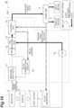
- a time measurement apparatus 10D of a fluorescence lifetime measurement apparatus 1D may include a TAC circuit 16 in addition to the configuration of the time measurement apparatus 10C described above. With such a configuration, even in a configuration in which a setting signal is output from the pulse generator 2, it is possible to derive the fluorescence lifetime with higher accuracy in consideration of the actual timing of fluorescence generation.
Landscapes
- Physics & Mathematics (AREA)
- Health & Medical Sciences (AREA)
- General Physics & Mathematics (AREA)
- Spectroscopy & Molecular Physics (AREA)
- Chemical & Material Sciences (AREA)
- Immunology (AREA)
- Biochemistry (AREA)
- Analytical Chemistry (AREA)
- Life Sciences & Earth Sciences (AREA)
- General Health & Medical Sciences (AREA)
- Nuclear Medicine, Radiotherapy & Molecular Imaging (AREA)
- Pathology (AREA)
- Chemical Kinetics & Catalysis (AREA)
- Optics & Photonics (AREA)
- Investigating, Analyzing Materials By Fluorescence Or Luminescence (AREA)
- Measurement Of Unknown Time Intervals (AREA)
Abstract
Description
- One aspect of the present invention relates to a time measurement apparatus, a fluorescence lifetime measurement apparatus, and a time measurement method.
- A time correlated single photon counting (TCSPC) apparatus that performs fluorescence lifetime measurement and the like is known (see, for example, Patent Literature 1). The TCSPC apparatus described in
Patent Literature 1 includes a plurality of time-digital-converter (TDC) circuits. The TDC circuit outputs a time measurement result as a digital signal. - [Patent Literature 1]
German Patent Application No. 102008004549 - In the TDC circuit described above and a TAC circuit that outputs a time measurement result as an analog signal, after a time is measured, a dead time in which a time cannot be measured again for a certain period of time is set. Due to the generation of the dead time, in a case where a phenomenon such as fluorescence is detected and time measurement related to the phenomenon (for example, fluorescence lifetime measurement) is performed, there is a concern that a time waveform for the phenomenon cannot be appropriately acquired. That is, since a time waveform cannot be acquired during a dead time, an accurate time waveform for the phenomenon may not be acquired even when time waveforms that could be obtained are synthesized.
- One aspect of the present invention has been made in view of the above circumstances, and relates to a time measurement apparatus, a fluorescence lifetime measurement apparatus, and a time measurement method which are capable of appropriately acquiring a time waveform related to a phenomenon.
- A time measurement apparatus according to an aspect of the present invention includes a first time measurement instrument configured to receive an input of a detection signal, which is a phenomenon detected and output by a detector, and output a measurement signal corresponding to a time associated with the detection signal, a gate unit configured to be provided between the detector and the first time measurement instrument and set to be in a first state where the detection signal is transmitted in a direction of the first time measurement instrument, or a second state where the detection signal is not transmitted in a direction of the first time measurement instrument, a setting unit configured to set a gate dead time during which the gate unit is set to be in the second state in the gate unit, and a derivation unit configured to derive and output time information related to the detection signal based on the measurement signal output from the first time measurement instrument, in which the setting unit sets a time, which is an integral multiple of a repetition period of the phenomenon detected by the detector and is longer than a dead time of the first time measurement instrument itself, in the gate unit as the gate dead time.
- In the time measurement apparatus according to an aspect of the present invention, switching is made between a first state where a detection signal is input to the first time measurement instrument that outputs a measurement signal corresponding to a time associated with the detection signal and a second state where the detection signal is not input. A gate dead time that is an integral multiple of a repetition period of the phenomenon and is longer than a dead time of the first time measurement instrument itself is set in the gate unit, and the first time measurement instrument is set to be in the second state described above during the gate dead time. In such a time measurement apparatus, a gate dead time that is an integral multiple of the repetition period of the phenomenon is set in the gate unit, and thus a time waveform in time information derived based on the measurement signal output from the first time measurement instrument is equivalent to a waveform that is temporally continuous before and after the dead time (non-measurement state). Further, in the time measurement apparatus, since the gate dead time set in the gate unit is longer than the dead time of the first time measurement instrument itself, the dead time of the first time measurement instrument does not occur in spite of a measurement state where a detection signal is input to the first time measurement instrument, and thus it is possible to appropriately secure continuity of a time waveform before and after the gate dead time described above. As described above, according to the time measurement apparatus of the aspect of the present invention, it is possible to appropriately (continuously) acquire a time waveform related to a phenomenon.
- The time measurement apparatus may further include a delay generation circuit, in which the setting unit may set a delay amount that is an integral multiple of the repetition period in the delay generation circuit, the delay generation circuit may receive an input of the detection signal that has passed through the gate unit set to be in the first state, and may output a delay signal delayed by the delay amount set by the setting unit with respect to the detection signal to the gate unit, and the gate unit may be set to be in the first state to transmit the detection signal, may be set to be in the second state until receiving an input of the delay signal, and may receive the input of the delay signal, and then may be set to be in the first state until a new detection signal is input. With such a configuration, it is possible to reliably set a gate dead time which is an integral multiple of a repetition period in the gate unit.
- The first time measurement instrument may include a time-amplitude converter that outputs the measurement signal corresponding to a time associated with the detection signal as an analog signal, and a converter that converts the analog signal output from the time-amplitude converter into a digital signal and outputs the digital signal. By using the time-amplitude converter, which outputs a measurement signal as an analog signal, and the converter, it is possible to increase a time resolution in the measurement of a phenomenon as compared with a case where, for example, a time-digital converter is used.
- The time measurement apparatus may further include a counter configured to output a count signal in accordance with a clock signal, in which the first time measurement instrument may receive inputs of the detection signal and the clock signal and output the measurement signal corresponding to a time between the detection signal and the clock signal, and the derivation unit may derive and output the time information based on the count signal output from the counter and the measurement signal output from the first time measurement instrument. With such a configuration, the counter operating in synchronization with a clock signal outputs a count signal so that rough time measurement (low time resolution and long time measurement) depending on the clock frequency is performed, and the first time-amplitude converter outputs a measurement signal corresponding to a time between a detection signal and the clock signal so that fine time measurement (high time resolution and short time measurement) for compensating for the measurement roughness of the counter is performed. Final time information is derived by combining these time measurement results, and thus it is possible to realize a high time resolution and long time measurement.
- A fluorescence lifetime measurement apparatus according to an aspect of the present invention is a fluorescence lifetime measurement apparatus that measures a lifetime of fluorescence emitted from a measurement target, the fluorescence lifetime measurement apparatus including a light source configured to generate light, the detector configured to detect the fluorescence from the measurement target irradiated with the light from the light source and output the detection signal, the time measurement apparatus configured to output time information related to the detection signal, and an arithmetic operation unit configured to derive a fluorescence lifetime of the measurement target based on the time information. With such a fluorescence lifetime measurement apparatus, it is possible to appropriately (continuously) acquire a time waveform of fluorescence lifetime by using the above-described time measurement apparatus. In order to acquire a time waveform of fluorescence lifetime, complicated light amount adjustment and delay adjustment have been required in the related art. However, according to the fluorescence lifetime measurement apparatus of the present invention, it is possible to easily acquire a time waveform of a fluorescence waveform without performing such complicated adjustment.
- The fluorescence lifetime measurement apparatus may further include a signal generation unit configured to generate a pulse signal for controlling output of light from the light source, in which the signal generation unit may output a setting signal indicating a repetition period of the fluorescence, which is synchronized with the pulse signal, to the setting unit. In this manner, the setting signal indicating the repetition period of the fluorescence, which is synchronized with the pulse signal, is output from the signal generation unit that generates the pulse signal, and thus the setting unit can appropriately set a gate dead time that is an integral multiple of a fluorescence repetition period in the gate unit.
- The arithmetic operation unit may output a setting signal indicating a repetition period of the fluorescence to the setting unit. In this manner, the setting signal indicating the repetition period of the fluorescence is output from the arithmetic operation unit, and thus the setting unit can appropriately set a gate dead time that is an integral multiple of a fluorescence repetition period in the gate unit.
- The fluorescence lifetime measurement apparatus may further include a signal generation unit configured to generate a pulse signal for controlling output of light from the light source, in which the signal generation unit may output a synchronization signal synchronized with the pulse signal, the time measurement apparatus may further include a second time measurement apparatus that outputs a signal corresponding to the synchronization signal, and the derivation unit may derive the time information based on the signal corresponding to the synchronization signal. Thereby, it is possible to derive the fluorescence lifetime with higher accuracy in consideration of the actual timing of fluorescence generation.
- A time measurement method according to an aspect of the present invention is a time measurement method executed by a time measurement apparatus, the time measurement method including setting a first dead time during which a detection signal, which is a phenomenon detected and output by a detector, is not input to a time measurement instrument to an integral multiple of a repetition period of the phenomenon, and deriving and outputting time information related to the detection signal based on the detection signal output from the time measurement instrument, in which the first dead time may be longer than a second dead time of the time measurement instrument itself.
- According to one aspect of the present invention, it is possible to appropriately acquire a time waveform related to a phenomenon.
-
-
FIG. 1 is a diagram schematically illustrating a fluorescence lifetime measurement apparatus according to the present embodiment. -
FIG. 2 is a diagram illustrating the principle of time measurement in a TAC circuit. -
FIG. 3 is a diagram illustrating the principle of time measurement in the TAC circuit. -
FIG. 4 is a diagram illustrating the principle of time measurement in the TAC circuit. -
FIG. 5 is a diagram illustrating acquisition of a time waveform. -
FIG. 6 is a diagram illustrating acquisition of a time waveform. -
FIG. 7 is a diagram illustrating acquisition of a time waveform. -
FIG. 8 is a diagram illustrating acquisition of a time waveform. -
FIG. 9 is a diagram illustrating acquisition of a time waveform. -
FIG. 10 is a diagram illustrating acquisition of a time waveform. -
FIG. 11 is a diagram illustrating acquisition of a time waveform. -
FIG. 12 is a diagram illustrating acquisition of a time waveform. -
FIG. 13 is a diagram illustrating acquisition of a time waveform according to a comparative example. -
FIG. 14 is a diagram illustrating acquisition of a time waveform according to a comparative example. -
FIG. 15 is a diagram illustrating acquisition of a time waveform according to a comparative example. -
FIG. 16 is a diagram illustrating acquisition of a time waveform according to a comparative example. -
FIG. 17 is a diagram illustrating acquisition of a time waveform according to a comparative example. -
FIG. 18 is a diagram illustrating acquisition of a time waveform according to a comparative example. -
FIG. 19 is a diagram schematically illustrating a fluorescence lifetime measurement apparatus according to a modification example. -
FIG. 20 is a diagram schematically illustrating a fluorescence lifetime measurement apparatus according to a modification example. -
FIG. 21 is a diagram schematically illustrating a fluorescence lifetime measurement apparatus according to a modification example. -
FIG. 22 is a diagram schematically illustrating a fluorescence lifetime measurement apparatus according to a modification example. - Hereinafter, embodiments of a time measurement apparatus, a time measurement method, and a fluorescence lifetime measurement apparatus according to an aspect of the present invention will be described in detail with reference to the drawings.
-
FIG. 1 is a diagram schematically illustrating a fluorescencelifetime measurement apparatus 1 according to the present embodiment. The fluorescencelifetime measurement apparatus 1 is a apparatus that measures the lifetime of fluorescence emitted from a sample S (measurement target). - Fluorescence spectra of organic materials and fluorescence probes are important parameters for controlling and evaluating the functions and characteristics of samples, such as a peak wavelength and fluorescence intensity. However, fluorescence spectra acquire temporally integrated information, and thus in a case where a sample contains a plurality of substances or reaction systems, only the integrated information can be obtained. In such a case, as means for evaluating the function and characteristics of a sample, fluorescence lifetime measurement for measuring a time required for the sample to return to a ground state after being photoexcited by pulsed light in a time domain of sub-nanoseconds to milliseconds is effective. In the fluorescence
lifetime measurement apparatus 1 according to the present embodiment, a fluorescence detection timing is derived by atime measurement apparatus 10 to be described below, the frequency distribution of the detection timing is obtained by detecting fluorescence a plurality of times, and the fluorescence lifetime of a sample S is estimated based on the frequency distribution. - As illustrated in
FIG. 1 , the fluorescencelifetime measurement apparatus 1 is configured to include a pulse generator 2 (signal generation unit), alight source 3, adetector 4, a computer 5 (arithmetic operation unit), adisplay apparatus 6, aninput apparatus 7, and atime measurement apparatus 10. Note that, inFIG. 1 , a clock generation circuit 9 (seeFIG. 2 ), which will be described later, in the configuration of the fluorescencelifetime measurement apparatus 1 is not illustrated. - The
pulse generator 2 generates a pulse signal for controlling the output of light from thelight source 3, and outputs the pulse signal to thelight source 3. Thepulse generator 2 generates a pulse signal based on an instruction given from thecomputer 5. More specifically, thepulse generator 2 receives a setting signal indicating a fluorescence repetition period from thecomputer 5 and generates a pulse signal according to the setting signal. - The
light source 3 outputs excitation light emitted to the sample S based on the pulse signals output from thepulse generator 2. That is, thelight source 3 irradiates the sample S with generated light. As thelight source 3, a light emitting diode (LED) light source, a laser light source, a super luminescent diode (SLD) light source, a lamp-based light source, or the like can be used. The intensity of the excitation light may be set, for example, to the extent that one photon is emitted when the sample S is irradiated with the excitation light. Fluorescence corresponding to the excitation light is output from the sample S irradiated with the excitation light. - The
detector 4 detects fluorescence from the sample S irradiated with light emitted from thelight source 3, and outputs a detection signal to a measurement gate 11 (details will be described later) of thetime measurement apparatus 10. As thedetector 4, a photomultiplier tube, an avalanche photodiode, a hybrid photo detector (HPD), a superconductive single photon detector (SSPD), or the like can be used. - The
computer 5 derives fluorescence lifetime based on the measurement results output from the time measurement apparatus 10 (in more detail, the control unit 14). Specifically, thecomputer 5 derives the frequency distribution of a fluorescence detection timing from time information of fluorescence (fluorescence detection timing) included in the measurement results, and obtains the fluorescence lifetime of the sample S from the frequency distribution. Thecomputer 5 also outputs a setting signal indicating a repetition period of fluorescence to thepulse generator 2 and thecontrol unit 14. Thecomputer 5 is constituted by an arithmetic operation unit such as a CPU and a storage unit such as a RAM or a flash memory. Note that thecomputer 5 may take charge of the function of thecontrol unit 14 of thetime measurement apparatus 10. - The
display apparatus 6 is a display electrically coupled to thecomputer 5, and displays analysis results for the fluorescence lifetime of the sample S described above. Theinput apparatus 7 is a keyboard, a mouse, or the like, and can input and set analysis conditions and measurement conditions for the fluorescence lifetime. - The
time measurement apparatus 10 is a time measurement apparatus that calculates a time from when a first trigger signal is input to when a second trigger signal is input as a measurement time. Thetime measurement apparatus 10 can be applied to various apparatuses and systems that derive a difference in input timing between two signals (the first trigger signal and the second trigger signal) input at different timings from the two signals. In the present embodiment, as described above, thetime measurement apparatus 10 is applied to the fluorescencelifetime measurement apparatus 1 that measures the lifetime of fluorescence emitted from the sample S. - As illustrated in
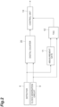
FIG. 1 , thetime measurement apparatus 10 includes a measurement gate 11 (first switching unit) and a time-analog-converter (TAC) circuit 12 (time-amplitude converter) and a TAC control unit 13 (converter) that constitute a first time measurement instrument, a control unit 14 (setting unit, derivation unit), and adelay generation circuit 30. Note that, inFIG. 1 , a digital counter 20 (seeFIG. 2 ), which will be described later, in the configuration of thetime measurement apparatus 10 is not illustrated. Thedigital counter 20 may be provided in theTAC control unit 13 or may be provided separately from theTAC control unit 13. - The
TAC circuit 12 is a circuit of a time-amplitude converter circuit that outputs a time difference between the input of the first trigger signal and the input of the second trigger signal as an analog signal (amplitude). TheTAC circuit 12 is configured to be able to measure, for example, a time of 10 ns. Specifically, theTAC circuit 12 outputs a detection signal, which is output by thedetector 4 detecting fluorescence (phenomenon), as a first trigger signal, outputs a clock signal output from the clock generation circuit 9 (seeFIG. 2 ) as a second trigger signal, and outputs an analog signal (amplitude) corresponding to a time between the detection signal and the clock signal as a measurement signal to theTAC control unit 13. That is, theTAC circuit 12 receives inputs of the detection signal, which is output by thedetector 4 detecting fluorescence (phenomenon), and the clock signal, and outputs the measurement signal corresponding to the time (time corresponding to the detection signal) between the detection signal and the clock signal. TheTAC circuit 12 receives the detection signal input through themeasurement gate 11. - The
TAC control unit 13 is an AD converter that converts the analog signal (amplitude), which is the measurement signal output from theTAC circuit 12, into a digital signal and outputs the digital signal. TheTAC control unit 13 outputs the digital signal after AD conversion to thecontrol unit 14 as a measurement signal. - The
measurement gate 11 receives an input of the detection signal, which is the first trigger signal, from thedetector 4 and outputs the detection signal to theTAC circuit 12. Themeasurement gate 11 is provided between thedetector 4 and theTAC circuit 12 and is set to be in a first state where the detection signal is transmitted in the direction of theTAC circuit 12 or a second state where the detection signal is not transmitted in the direction of theTAC circuit 12. That is, themeasurement gate 11 is set to be in any one of the first state or the second state at all times. A dead time (gate dead time) is set in themeasurement gate 11. The dead time (gate dead time) here means a time during which themeasurement gate 11 is set to be in a state where the detection signal is not transmitted in the direction of theTAC circuit 12, that is, the above-described second state. The gate dead time is set by the control unit 14 (setting unit) through thedelay generation circuit 30, and is a time which is an integral multiple of a repetition period of a phenomenon (for example, fluorescence detected by the detector 4). In addition, the gate dead time set by thecontrol unit 14 is longer than the dead time of theTAC circuit 12 itself. The dead time of theTAC circuit 12 itself is a time during which theTAC circuit 12 cannot measure a time again for a certain period of time after measuring the time. - In detail, the
measurement gate 11 receives a delay signal from thedelay generation circuit 30, and is switched between the above-described first state and second state based on the delay signal. That is, themeasurement gate 11 is set to be in the first state to transmit the detection signal and is then set to be in the second state until the delay signal is input. After themeasurement gate 11 receives the input of the delay signal, themeasurement gate 11 is set to be in the first state until a new detection signal is input. The delay signal is a signal delayed by a delay amount that is an integral multiple of a fluorescence repetition period (details will be described later). For this reason, themeasurement gate 11 is set to be in the second state until the delay signal is input after the detection signal is transmitted, and thus a gate dead time being the second state can be appropriately set to an integral multiple of a fluorescence repetition period. - The
control unit 14 function as a setting unit that sets a gate dead time during which themeasurement gate 11 is set to be in the second state, in themeasurement gate 11 and a derivation unit that derives and outputs time information related to a detection signal based on the measurement signal output from theTAC control unit 13. - As a function as the setting unit, the
control unit 14 sets a time, which is a time being an integral multiple of a repetition period of fluorescence detected by thedetector 4 and is longer than the dead time of theTAC circuit 12 itself, in themeasurement gate 11 as a gate dead time. Thecontrol unit 14 sets the gate dead time in themeasurement gate 11 via thedelay generation circuit 30. Thecontrol unit 14 performs the delay control of thedelay generation circuit 30 based on a setting signal (a signal indicating a fluorescence repetition period) which is input from thecomputer 5. That is, thecontrol unit 14 sets a delay amount, which is an integral multiple of the repetition period, in thedelay generation circuit 30 in advance based on the setting signal. Thedelay generation circuit 30 outputs a delay signal delayed by the set delay amount to themeasurement gate 11. In detail, thedelay generation circuit 30 is configured such that a detection signal having passed through themeasurement gate 11 set to be in the first state is input (the detection signal is input similarly to the TAC circuit 12), and outputs the delay signal delayed by the delay amount set by thecontrol unit 14 for the detection signal to themeasurement gate 11 when receiving the input of the detection signal. As described above, themeasurement gate 11 is set to be in the second state (the state of the gate dead time) until themeasurement gate 11 receives an input of the delay signal after transmitting the detection signal. Thereby, the gate dead time of themeasurement gate 11 can be set to an integral multiple of a fluorescence repetition period. - As a function as a derivation unit, the
control unit 14 derives and outputs time information related on a detection signal detected by thedetector 4, based on a count signal output from the digital counter 20 (seeFIG. 2 ) and a measurement signal output from theTAC circuit 12 and converted into a digital signal by theTAC control unit 13. As illustrated inFIG. 2 , thedigital counter 20 is a counter to which a detection signal from thedetector 4 and a clock signal from theclock generation circuit 9 are input. Thedigital counter 20 operates in synchronization with the clock signal and outputs the count signal to thecontrol unit 14 in accordance with the clock signal (by counting the clock signal). Although thedigital counter 20 can perform long-time measurement for a detection signal, it is difficult to increase a time resolution. Thecontrol unit 14 combines a time measurement result of thedigital counter 20 and a time measurement result of theTAC circuit 12 with a high time resolution to achieve high time resolution and long-time measurement of time information related to the detection signal. -
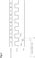
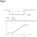
FIGS. 3 and4 are diagrams illustrating the derivation of the time information described above. InFIGS. 3 and4 , the horizontal axis indicates a time axis. As illustrated inFIG. 3 , thedigital counter 20 counts clock signals and outputs a count signal.FIG. 3 illustrates an example in which thedigital counter 20 outputs count signals indicating 23, 24, 25, 26, 27, and 28. As described above, thedigital counter 20 operates in synchronization with a clock signal. In addition, as illustrated inFIG. 3 , now, it is assumed that theTAC circuit 12 measures a time difference T between the input of a detection signal TRG1 from thedetector 4 and the input of a clock signal TRG2 immediately after the detection signal TRG1. In the measurement signal output by theTAC circuit 12, as illustrated inFIG. 4 , a voltage (amplitude) is started to increase in response to the detection signal TRG1 from a timing (time 11) when the detection signal TRG1 is input, and a voltage (amplitude) becomes constant in response to the clock signal TRG2 from a timing (time t2) when the clock signal TRG2 is input. - The
control unit 14 derives time information indicating a time until a detection signal is input to theTAC circuit 12 by subtracting a time indicated by the measurement signal from a time corresponding to a count value indicated by the count signal. That is, in the example illustrated inFIG. 3 , thecontrol unit 14 derives time information (23-T) indicating a time until the detection signal TRG1 is input to theTAC circuit 12 by subtracting a time difference T, which is time information indicated by the measurement signal, from 23 which is a time corresponding to the count value indicated by the count signal. Such time information can be derived by correspondence of the clock signal input to thedigital counter 20 and the clock signal input to the TAC circuit 12 (the count value indicated by the clock signal input to theTAC circuit 12 is uniquely determined). Thecontrol unit 14 outputs the derived time information (measurement result) to thecomputer 5. - Next, the meaning (effect) of setting a gate dead time that is an integral multiple of a fluorescence repetition period will be described with reference to
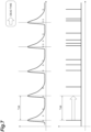
FIGS. 5 to 18 .FIGS. 5 to 12 are diagrams illustrating acquisition of a fluorescence time waveform in the fluorescencelifetime measurement apparatus 1 according to the present embodiment.FIGS. 13 to 18 are diagrams illustrating acquisition of a fluorescence time waveform in the fluorescencelifetime measurement apparatus 1 according to a comparative example. InFIGS. 5 to 18 , the horizontal axis represents a time. - Now, a case where fluorescence with a repetition period is incident as illustrated in the upper part of
FIG. 5 is conceivable. In an example illustrated inFIG. 5 , the number of frequencies of a pulse signal output from thepulse generator 2 is 1 MHz, and a fluorescence repetition period of 1 µs. It is assumed that fluorescence emission occurs along a curve illustrated in the upper part ofFIG. 5 , and that a plurality of squares illustrated in the upper part ofFIG. 5 indicate the generation of photons associated with fluorescence (hereinafter, the same applies toFIG. 6 and the subsequent drawings). In a lower part ofFIG. 5 , detection signals output from thedetector 4 are illustrated. As illustrated in the lower part ofFIG. 5 , a detection signal corresponding to each photon is output from thedetector 4 at a timing when each photon is detected due to the generation of the photons. - Here, in the
TAC circuit 12, after a photon is input (after a time is measured), a dead time during which a time cannot be measured again for a certain period of time occurs. In a general fluorescence lifetime measurement apparatus (for example, a fluorescence lifetime measurement apparatus according to a comparative example to be described later), there is an attempt to reduce a dead time of the apparatus as much as possible in order to reduce the number of photons that are not counted, and a dead time other than the dead time of theTAC circuit 12 itself is not provided. In this regard, in the fluorescencelifetime measurement apparatus 1 according to the present embodiment, a time that is an integral multiple of a fluorescence repetition period (and is longer than the dead time of theTAC circuit 12 itself) is set in themeasurement gate 11 as a gate dead time. In a lower part ofFIG. 6 , an example in which a gate dead time that is one time the fluorescence repetition period (the same as a fluorescence repetition period) is set in themeasurement gate 11 is indicated. Note that a "dead time" in each ofFIGS. 6 to 10 indicates a gate dead time. - When a gate dead time (first gate dead time) illustrated in
FIG. 6 occurs after a first photon is measured, a signal during the first gate dead time cannot be acquired, and thus a detection signal that actually passes through themeasurement gate 11 is as illustrated in a lower part ofFIG. 7 in consideration of the first gate dead time. In addition, when the first gate dead time is terminated, and the next photon is measured, a gate dead time (second gate dead time) illustrated inFIG. 8 occurs again. Since a signal cannot be acquired even during the second gate dead time, a detection signal that actually passes through themeasurement gate 11 is as illustrated in a lower part ofFIG. 9 in consideration of the second gate dead time. In this manner, when a gate dead time occurring after photon measurement is repeated, a detection signal that actually passes through themeasurement gate 11 is as illustrated inFIG. 10 . - Here, a time during which time measurement can be performed by such a fluorescence lifetime measurement apparatus (a time during which photons can be measured at any time when photons are generated) is a time indicated by a "measured region" in
FIG. 11 . Such a state of time is a measurement standby state where measurement can be performed whenever photons are input. The measurement standby state is a time during which the fluorescencelifetime measurement apparatus 1 actually performs time measurement. Then, as illustrated inFIG. 12 , when the "measured regions" are arranged in order of occurrence on the time axis, it can be understood that the original fluorescence emission curve appears. This is because the gate dead time is set to an integral multiple (one time in this case) of a fluorescence repetition period, and time waveforms before and after each dead time being synthesized are equivalent to a waveform of a temporally continuous fluorescence curve. As described above, it is possible to perform measurement as if continuous measurement has been performed (continuous acquisition of fluorescence waveforms) by setting a dead time that is an integral multiple of a fluorescence repetition period in themeasurement gate 11. - Next, a configuration in which a gate dead time is not set (a configuration according to a comparative example) will be described with reference to
FIGS. 13 to 18 . Note that a "dead time" in each ofFIGS. 13 to 16 means a dead time of the TAC circuit itself instead of a gate dead time. In the configuration according to the comparative example, as illustrated in the upper part ofFIG. 13 , a fluorescence repetition period is set to 1 µs, and a gate dead time is not set. Since a gate dead time is not set, dead time after photons are detected is only the dead time of the TAC circuit itself (which is a dead time shorter than the above-described gate dead time) as illustrated in the lower part ofFIG. 13 . After a first photon is measured, the dead time illustrated inFIG. 13 occurs, and photons cannot be measured during the dead time. In addition, when the first dead time is terminated, photons can be measured as illustrated in the lower part ofFIG. 14 , and a dead time occurs again after the photons are measured. When a second dead time is terminated, photons can be measured as illustrated in the lower part ofFIG. 15 , and a dead time occurs again after the photons are measured. In this manner, when the setting of a gate dead time after photon measurement is repeated, a detection signal that actually passes through a measurement gate is as illustrated inFIG. 16 . In addition, when "measured regions" illustrated inFIG. 17 are arranged in order of occurrence on the time axis, a waveform illustrated inFIG. 18 is formed. The waveform is different from the above-described waveform illustrated inFIG. 12 and does not match the waveform of the original fluorescence curve at all. In this manner, in a configuration in which a dead time that is an integral multiple of a fluorescence repetition period is not set, it is not possible to perform measurement (continuous acquisition of fluorescence waveforms) as if continuous measurement has been performed. - Next, operations and effects of the
time measurement apparatus 10 and the fluorescencelifetime measurement apparatus 1 according to the present embodiment will be described. - The
time measurement apparatus 10 according to the present embodiment includes theTAC circuit 12 that receives an input of a detection signal, which is a phenomenon detected and output by thedetector 4, and outputs a measurement signal corresponding to a time associated with the detection signal, themeasurement gate 11 which is provided between thedetector 4 and theTAC circuit 12 and is set to be in a first state where the detection signal is transmitted in the direction of theTAC circuit 12 or a second state where the detection signal is not transmitted in the direction of theTAC circuit 12, thecontrol unit 14 that functions as a setting unit for setting a gate dead time, which is a time during which themeasurement gate 11 is set to be in the second state, in themeasurement gate 11, and thecontrol unit 14 that functions as a derivation unit for deriving and outputting time information related to the detection signal based on the measurement signal output from theTAC circuit 12. Thecontrol unit 14 functioning as a setting unit sets a time, which is an integral multiple of a repetition period of fluorescence detected by thedetector 4 and is longer than a dead time of theTAC circuit 12 itself, in themeasurement gate 11 as a gate dead time. - In the
time measurement apparatus 10 according to the present embodiment, switching is made between a first state where a detection signal is input to theTAC circuit 12 that outputs a measurement signal corresponding to a time associated with the detection signal and a second state where the detection signal is not input. A gate dead time that is an integral multiple of a repetition period of fluorescence and is longer than a dead time of theTAC circuit 12 itself is set in themeasurement gate 11, and themeasurement gate 11 is set to be in the second state described above during the gate dead time. In such atime measurement apparatus 10, a gate dead time that is an integral multiple of the repetition period of fluorescence is set in themeasurement gate 11, and thus a time waveform in time information derived based on the measurement signal output from theTAC circuit 12 is equivalent to a waveform that is temporally continuous before and after the dead time (non-measurement state). Further, in thetime measurement apparatus 10, since the gate dead time set in themeasurement gate 11 is longer than the dead time of theTAC circuit 12 itself, the dead time of theTAC circuit 12 itself does not occur in spite of a measurement state where a detection signal is input to theTAC circuit 12, and thus it is possible to appropriately secure continuity of a time waveform before and after the gate dead time described above. As described above, according to thetime measurement apparatus 10 of the present embodiment, it is possible to appropriately (continuously) acquire a time waveform related to a phenomenon. - The
time measurement apparatus 10 may further include thedelay generation circuit 30, thecontrol unit 14 functioning as a setting unit may set a delay amount that is an integral multiple of a repetition period in thedelay generation circuit 30, thedelay generation circuit 30 may receive an input of a detection signal having passed through themeasurement gate 11 set to be in a first state and output a delay signal delayed by the delay amount set by thecontrol unit 14 functioning as a setting unit with respect to the detection signal to themeasurement gate 11, and themeasurement gate 11 may be set to be in the first state to transmit the detection signal, set to be in a second state until an input of the delay signal is received, receive the input of the delay signal, and then set to be in the first state until a new detection signal is input. With such a configuration, a gate dead time that is an integral multiple of a repetition period can be reliably set in themeasurement gate 11. - The first time measurement instrument may include the
TAC circuit 12 that outputs a measurement signal corresponding to a time associated with a detection signal as an analog signal, and theTAC control unit 13 that converts the analog signal output from theTAC circuit 12 into a digital signal and outputs it. By using theTAC circuit 12, which outputs a measurement signal as an analog signal, and theTAC control unit 13, it is possible to increase a time resolution in the measurement of a phenomenon as compared with a case where, for example, a time-digital converter is used. - The
time measurement apparatus 10 may further include thedigital counter 20 that outputs a count signal in accordance with a clock signal, theTAC circuit 12 may receive inputs of a detection signal and the clock signal and output a measurement signal corresponding to a time between the detection signal and the clock signal, and thecontrol unit 14 functioning as a derivation unit may derive and output time information based on a count signal output from thedigital counter 20 and the measurement signal output from theTAC circuit 12. With such a configuration, thedigital counter 20, which operates in synchronization with the clock signal, outputs the count signal to perform rough time measurement (a low time resolution and long-time measurement) depending on the frequency of a clock, and theTAC circuit 12 outputs a measurement signal corresponding to a time between the detection signal and the clock signal to perform fine time measurement (a high time resolution and short-time measurement) that compensates for the measurement roughness of thedigital counter 20. By combining these time measurement results and deriving final time information, it is possible to achieve a high time resolution and long-time measurement. - A fluorescence
lifetime measurement apparatus 1 according to the present embodiment, which is a fluorescence lifetime measurement apparatus that measures the lifetime of fluorescence emitted from a sample S, includes thelight source 3 that irradiates the sample S with generated light, thedetector 4 that detects fluorescence from the sample S irradiated with light from thelight source 3 and outputs the detection signal, thetime measurement apparatus 10 that outputs time information related to the detection signal, and thecomputer 5 that derives the fluorescence lifetime of the sample S based on the time information. With such a fluorescencelifetime measurement apparatus 1, a time waveform of the fluorescence lifetime can be appropriately (continuously) acquired using thetime measurement apparatus 10 described above. - The
computer 5 may output a setting signal indicating a fluorescence repetition period to thecontrol unit 14 functioning as a setting unit. In this manner, thecontrol unit 14 functioning as a setting unit can appropriately set a gate dead time, which is an integral multiple of the fluorescence repetition period, in themeasurement gate 11 by outputting the setting signal indicating the fluorescence repetition period from thecomputer 5. - Although an embodiment of the present invention has been described above, the present invention is not limited to the above embodiment. For example, as illustrated in
FIG. 19 , atime measurement apparatus 10A of a fluorescencelifetime measurement apparatus 1A may further include aTAC circuit 16. TheTAC circuit 16 is a circuit of a time-amplitude converter that outputs a time difference between the input of a first trigger signal and the input of a second trigger signal as an analog signal (amplitude). TheTAC circuit 16 outputs a signal corresponding to a synchronization signal of a phenomenon associated with a detection signal detected by thedetector 4. The phenomenon associated with the detection signal detected by thedetector 4 is fluorescence from the sample S detected by thedetector 4. The synchronization signal of the phenomenon is a signal output by thepulse generator 2, and is a signal synchronized with (for example, the same as) the pulse signal. Specifically, theTAC circuit 16 outputs a synchronization signal as a first trigger signal, outputs a clock signal output from theclock generation circuit 9 as a second trigger signal, outputs an analog signal (amplitude) corresponding to a time difference between the synchronization signal and the clock signal as a signal corresponding to the above-mentioned synchronization signal to theTAC control unit 13. In this case, thecontrol unit 14 functioning as a derivation unit may derive time information further in consideration of the signal corresponding to the above-mentioned synchronization signal output from the TAC circuit 16 (based on the signal). That is, thecontrol unit 14 may specify a start timing (start point) of the phenomenon from the signal corresponding to the synchronization signal, and may derive time information related to the detection signal detected by thedetector 4 with higher accuracy. Thereby, it is possible to derive the fluorescence lifetime with higher accuracy in consideration of the actual timing of fluorescence generation. - In addition, as illustrated in
FIG. 20 , atime measurement apparatus 10B of a fluorescencelifetime measurement apparatus 1B may include twoTAC circuits TAC circuit 16 and may further include areference gate 15. In addition, thetime measurement apparatus 10B may include twoTAC control units TAC control unit 13. TheTAC circuit 16a outputs a signal corresponding to the above-described synchronization signal to theTAC control unit 13b. In addition, theTAC circuit 16b outputs a signal corresponding to the above-described synchronization signal to theTAC control unit 13b. TheTAC control unit 13b converts signals input from theTAC circuits control unit 14. Note that, in this case, a signal output from theTAC circuit 12 is output to theTAC control unit 13a, and theTAC control unit 13a converts the signal input from theTAC circuit 12 into a digital signal and outputs it to thecontrol unit 14. Thereference gate 15 switches between theTAC circuits TAC circuits 16. Thereference gate 15 receives the synchronization signal input from thepulse generator 2 and outputs a synchronization signal to only one of theTAC circuits reference gate 15 switches between theTAC circuits TAC circuits TAC circuits reference gate 15 are switched, and thus it is possible to appropriately avoid deterioration in signal measurement efficiency due to the influence of a dead time in theTAC circuit 16. - In addition, as illustrated in
FIG. 21 , like a fluorescencelifetime measurement apparatus 1C including atime measurement apparatus 10C, thepulse generator 2 may output a setting signal indicating a fluorescence repetition period synchronized with a pulse signal to thecontrol unit 14 functioning as a setting unit. In this manner, the setting signal indicating the fluorescence repetition period synchronized with the pulse signal is output from thepulse generator 2 that generates the pulse signal, and thus thecontrol unit 14 functioning as a setting unit can appropriately set a gate dead time, which is an integral multiple of the fluorescence repetition period, in themeasurement gate 11. - Further, as illustrated in
FIG. 22 , atime measurement apparatus 10D of a fluorescencelifetime measurement apparatus 1D may include aTAC circuit 16 in addition to the configuration of thetime measurement apparatus 10C described above. With such a configuration, even in a configuration in which a setting signal is output from thepulse generator 2, it is possible to derive the fluorescence lifetime with higher accuracy in consideration of the actual timing of fluorescence generation. -
- 1, 1A, 1B, 1C, 1D Fluorescence lifetime measurement apparatus
- 2 Pulse generator (signal generation unit)
- 3 Light source
- 4 Detector
- 5 Computer (arithmetic operation unit)
- 10, 10A, 10B, 10C, 10D Time measurement apparatus
- 11 Measurement gate (gate unit)
- 12 TAC circuit (time-amplitude converter)
- 13 TAC control unit (converter)
- 14 Control unit (setting unit, derivation unit)
- 15 Reference gate
- 16 TAC circuit (second time measurement instrument)
- 20 digital counter
- 30 delay generation circuit
Claims (9)
- A time measurement apparatus comprising:a first time measurement instrument configured to receive an input of a detection signal, which is a phenomenon detected and output by a detector, and output a measurement signal corresponding to a time associated with the detection signal;a gate unit configured to be provided between the detector and the first time measurement instrument and set to be in a first state where the detection signal is transmitted in a direction of the first time measurement instrument, or a second state where the detection signal is not transmitted in a direction of the first time measurement instrument;a setting unit configured to set a gate dead time during which the gate unit is set to be in the second state in the gate unit; anda derivation unit configured to derive and output time information related to the detection signal based on the measurement signal output from the first time measurement instrument,wherein the setting unit sets a time, which is an integral multiple of a repetition period of the phenomenon detected by the detector and is longer than a dead time of the first time measurement instrument itself, in the gate unit as the gate dead time.
- The time measurement apparatus according to claim 1, further comprising:a delay generation circuit,wherein the setting unit sets a delay amount that is an integral multiple of the repetition period in the delay generation circuit,the delay generation circuit receives an input of the detection signal that has passed through the gate unit set to be in the first state, and outputs a delay signal delayed by the delay amount set by the setting unit with respect to the detection signal to the gate unit, andthe gate unit is set to be in the first state to transmit the detection signal, is set to be in the second state until receiving an input of the delay signal, and receives the input of the delay signal, and then is set to be in the first state until a new detection signal is input.
- The time measurement apparatus according to claim 1 or 2, wherein the first time measurement instrument includes a time-amplitude converter that outputs the measurement signal corresponding to a time associated with the detection signal as an analog signal, and a converter that converts the analog signal output from the time-amplitude converter into a digital signal and outputs the digital signal.
- The time measurement apparatus according to any one of claims 1 to 3, further comprising:a counter configured to output a count signal in accordance with a clock signal,wherein the first time measurement instrument receives inputs of the detection signal and the clock signal and outputs the measurement signal corresponding to a time between the detection signal and the clock signal, andthe derivation unit derives and outputs the time information based on the count signal output from the counter and the measurement signal output from the first time measurement instrument.
- A fluorescence lifetime measurement apparatus that measures a lifetime of fluorescence emitted from a measurement target, the fluorescence lifetime measurement apparatus comprising:a light source configured to generate light;the detector configured to detect the fluorescence from the measurement target irradiated with the light from the light source and output the detection signal;the time measurement apparatus according to any one of claims 1 to 4, which is configured to output time information related to the detection signal; andan arithmetic operation unit configured to derive a fluorescence lifetime of the measurement target based on the time information.
- The fluorescence lifetime measurement apparatus according to claim 5, further comprising:a signal generation unit configured to generate a pulse signal for controlling output of light from the light source,wherein the signal generation unit outputs a setting signal indicating a repetition period of the fluorescence, which is synchronized with the pulse signal, to the setting unit.
- The fluorescence lifetime measurement apparatus according to claim 5 or 6, wherein the arithmetic operation unit outputs a setting signal indicating a repetition period of the fluorescence to the setting unit.
- The fluorescence lifetime measurement apparatus according to claims 5 to 7, further comprising:a signal generation unit configured to generate a pulse signal for controlling output of light from the light source,wherein the signal generation unit outputs a synchronization signal synchronized with the pulse signal,the time measurement apparatus further includes a second time measurement instrument that outputs a signal corresponding to the synchronization signal, andthe derivation unit derives the time information based on the signal corresponding to the synchronization signal.
- A time measurement method executed by a time measurement apparatus, the time measurement method comprising:setting a first dead time during which a detection signal, which is a phenomenon detected and output by a detector, is not input to a time measurement instrument to an integral multiple of a repetition period of the phenomenon; andderiving and outputting time information related to the detection signal based on the detection signal output from the time measurement instrument,wherein the first dead time is longer than a second dead time of the time measurement instrument itself.
Applications Claiming Priority (2)
| Application Number | Priority Date | Filing Date | Title |
|---|---|---|---|
| JP2020133842 | 2020-08-06 | ||
| PCT/JP2021/018264 WO2022030063A1 (en) | 2020-08-06 | 2021-05-13 | Time measurement device, fluorescence lifetime measurement device, and time measurement method |
Publications (3)
| Publication Number | Publication Date |
|---|---|
| EP4174588A1 true EP4174588A1 (en) | 2023-05-03 |
| EP4174588A4 EP4174588A4 (en) | 2024-07-17 |
| EP4174588B1 EP4174588B1 (en) | 2024-12-04 |
Family
ID=80117844
Family Applications (1)
| Application Number | Title | Priority Date | Filing Date |
|---|---|---|---|
| EP21854514.3A Active EP4174588B1 (en) | 2020-08-06 | 2021-05-13 | Time measurement device, fluorescence lifetime measurement device, and time measurement method |
Country Status (7)
| Country | Link |
|---|---|
| US (1) | US12625074B2 (en) |
| EP (1) | EP4174588B1 (en) |
| JP (1) | JP7529785B2 (en) |
| KR (1) | KR102850441B1 (en) |
| CN (1) | CN115735115B (en) |
| TW (1) | TWI869604B (en) |
| WO (1) | WO2022030063A1 (en) |
Family Cites Families (19)
| Publication number | Priority date | Publication date | Assignee | Title |
|---|---|---|---|---|
| SU1468251A1 (en) | 1987-03-31 | 1992-04-15 | Предприятие П/Я В-2679 | Converter of time intervals to digital code |
| JP2680398B2 (en) * | 1989-03-08 | 1997-11-19 | 浜松ホトニクス株式会社 | Optical waveform measurement device |
| JPH0749308A (en) | 1993-08-05 | 1995-02-21 | Horiba Ltd | Fluorescence life measuring apparatus |
| JP3251260B2 (en) * | 1999-04-07 | 2002-01-28 | エヌイーシーマイクロシステム株式会社 | Slew rate detection circuit and semiconductor integrated circuit device |
| JP3793531B2 (en) * | 2003-10-07 | 2006-07-05 | オリンパス株式会社 | Fluorescence lifetime measuring device |
| US8072933B2 (en) | 2005-03-30 | 2011-12-06 | Nokia Corporation | Combined handover of the circuit-switched (CS) and packet-switched (PS) resources |
| US7893409B1 (en) | 2007-05-25 | 2011-02-22 | Sunpower Corporation | Transient photoluminescence measurements |
| DE102008004549B4 (en) | 2008-01-15 | 2013-04-18 | PicoQuant GmbH. Unternehmen für optoelektronische Forschung und Entwicklung | Apparatus and method for simultaneous time resolved single photon registration from a plurality of detection channels |
| JP5213808B2 (en) | 2009-07-28 | 2013-06-19 | 三菱電機株式会社 | Time measurement circuit |
| US8330123B2 (en) * | 2010-01-28 | 2012-12-11 | I.S.S. (Usa), Inc. | System and method for digital parallel frequency fluorometry |
| JP2011235465A (en) | 2010-05-06 | 2011-11-24 | Canon Inc | Printer, and method for measuring elapsed time in printer |
| CN101944838B (en) | 2010-07-29 | 2012-12-26 | 浙江大学 | Current state judging and dead zone compensating method based on IGBT (Insulated Gate Bipolar Translator) drive chip short-circuit protection |
| DE102011055330B4 (en) | 2011-11-14 | 2024-10-31 | Leica Microsystems Cms Gmbh | Method for measuring the lifetime of an excited state in a sample |
| US8786474B1 (en) | 2013-03-15 | 2014-07-22 | Kabushiki Kaisha Toshiba | Apparatus for programmable metastable ring oscillator period for multiple-hit delay-chain based time-to-digital circuits |
| JP5978266B2 (en) | 2014-09-03 | 2016-08-24 | 浜松ホトニクス株式会社 | Time measuring device, time measuring method, light emitting lifetime measuring device, and light emitting lifetime measuring method |
| CN105262504B (en) | 2015-11-11 | 2018-02-16 | 中国电子科技集团公司第四十一研究所 | The time and frequency measurement circuit and method of a kind of wide interval frequency hopping signal |
| CN105529951B (en) | 2016-02-05 | 2017-11-07 | 厦门大学 | The variable inversion controlling method of dead time and system of belt current zero passage Region control |
| EP3465156B1 (en) | 2016-05-25 | 2020-03-18 | Leica Microsystems CMS GmbH | Fluorescence lifetime microscopic method with time-correlated single photon counting which allows higher light intensities, and corresponding device |
| CN108489947B (en) | 2018-03-22 | 2021-02-09 | 深圳大学 | Method and device for measuring fluorescence lifetime |
-
2021
- 2021-05-13 CN CN202180046534.6A patent/CN115735115B/en active Active
- 2021-05-13 WO PCT/JP2021/018264 patent/WO2022030063A1/en not_active Ceased
- 2021-05-13 US US18/017,694 patent/US12625074B2/en active Active
- 2021-05-13 EP EP21854514.3A patent/EP4174588B1/en active Active
- 2021-05-13 KR KR1020227043968A patent/KR102850441B1/en active Active
- 2021-05-13 JP JP2022541120A patent/JP7529785B2/en active Active
- 2021-06-18 TW TW110122430A patent/TWI869604B/en active
Also Published As
| Publication number | Publication date |
|---|---|
| KR20230047327A (en) | 2023-04-07 |
| US12625074B2 (en) | 2026-05-12 |
| TW202210859A (en) | 2022-03-16 |
| WO2022030063A1 (en) | 2022-02-10 |
| JPWO2022030063A1 (en) | 2022-02-10 |
| EP4174588B1 (en) | 2024-12-04 |
| KR102850441B1 (en) | 2025-08-26 |
| EP4174588A4 (en) | 2024-07-17 |
| TWI869604B (en) | 2025-01-11 |
| CN115735115B (en) | 2025-04-08 |
| JP7529785B2 (en) | 2024-08-06 |
| US20230288335A1 (en) | 2023-09-14 |
| CN115735115A (en) | 2023-03-03 |
Similar Documents
| Publication | Publication Date | Title |
|---|---|---|
| US11125863B2 (en) | Correction device, correction method, and distance measuring device | |
| US10073034B2 (en) | Method for measuring the lifetime of an excited state in a sample | |
| US10962932B2 (en) | Time measurement device, time measurement method, light-emission-lifetime measurement device, and light-emission-lifetime measurement method | |
| US9709497B2 (en) | Transient absorption measurement method and transient absorption measurement apparatus | |
| US20190339201A1 (en) | Fluorescence lifetime imaging microscopy method having time-correlated single-photon counting, which method permits higher light intensities | |
| JPH07306140A (en) | Time-resolved optical array detector and CCD camera for frequency domain fluorometry and / or phosphorometry | |
| CN101310195B (en) | Device for the detection of surroundings | |
| US12625074B2 (en) | Time measurement device, fluorescence lifetime measurement device, and time measurement method | |
| US12618951B2 (en) | Light detection device, light detection method and optical distance sensor | |
| EP4170436A1 (en) | Time measuring device, fluorescence lifetime measuring device, and time measuring method | |
| JP2680398B2 (en) | Optical waveform measurement device | |
| TW202223559A (en) | Time measuring device, fluorescence lifetime measuring device, and time measuring method | |
| Patel et al. | Gated integrator PXI-DAQ system for Thomson scattering diagnostics | |
| KR101817332B1 (en) | Measurement Method of Time-Information using Digital oscilloscope In Pulsed Laser Optical System | |
| Markovic et al. | Smart-pixel for 3D ranging imagers based on single-photon avalanche diode and time-to-digital converter | |
| CN116147767A (en) | A transient spectrometer acquisition time measurement device and measurement method | |
| Thomas et al. | Time domain measurements at Diamond | |
| Olsson | Direct measurement of fluorescence lifetime using high speed data acquisition | |
| Markovic et al. | 15bit Time-to-Digital Converters with 0.9% DNL rms and 160ns FSR for single-photon imagers | |
| Markovic et al. | Towards arrays of smart-pixels for time-correlated single photon counting and time of flight application | |
| JPH02234050A (en) | Light wave measuring device |
Legal Events
| Date | Code | Title | Description |
|---|---|---|---|
| STAA | Information on the status of an ep patent application or granted ep patent |
Free format text: STATUS: THE INTERNATIONAL PUBLICATION HAS BEEN MADE |
|
| PUAI | Public reference made under article 153(3) epc to a published international application that has entered the european phase |
Free format text: ORIGINAL CODE: 0009012 |
|
| STAA | Information on the status of an ep patent application or granted ep patent |
Free format text: STATUS: REQUEST FOR EXAMINATION WAS MADE |
|
| 17P | Request for examination filed |
Effective date: 20230124 |
|
| AK | Designated contracting states |
Kind code of ref document: A1 Designated state(s): AL AT BE BG CH CY CZ DE DK EE ES FI FR GB GR HR HU IE IS IT LI LT LU LV MC MK MT NL NO PL PT RO RS SE SI SK SM TR |
|
| DAV | Request for validation of the european patent (deleted) | ||
| DAX | Request for extension of the european patent (deleted) | ||
| REG | Reference to a national code |
Ipc: G01N0021640000 Ref country code: DE Ref legal event code: R079 Ref document number: 602021023055 Country of ref document: DE Free format text: PREVIOUS MAIN CLASS: G04F0010000000 |
|
| A4 | Supplementary search report drawn up and despatched |
Effective date: 20240614 |
|
| RIC1 | Information provided on ipc code assigned before grant |
Ipc: G04F 10/00 20060101ALI20240610BHEP Ipc: G01N 21/64 20060101AFI20240610BHEP |
|
| GRAP | Despatch of communication of intention to grant a patent |
Free format text: ORIGINAL CODE: EPIDOSNIGR1 |
|
| STAA | Information on the status of an ep patent application or granted ep patent |
Free format text: STATUS: GRANT OF PATENT IS INTENDED |
|
| RIC1 | Information provided on ipc code assigned before grant |
Ipc: G01N 21/64 20060101AFI20240725BHEP |
|
| INTG | Intention to grant announced |
Effective date: 20240827 |
|
| GRAS | Grant fee paid |
Free format text: ORIGINAL CODE: EPIDOSNIGR3 |
|
| GRAA | (expected) grant |
Free format text: ORIGINAL CODE: 0009210 |
|
| STAA | Information on the status of an ep patent application or granted ep patent |
Free format text: STATUS: THE PATENT HAS BEEN GRANTED |
|
| AK | Designated contracting states |
Kind code of ref document: B1 Designated state(s): AL AT BE BG CH CY CZ DE DK EE ES FI FR GB GR HR HU IE IS IT LI LT LU LV MC MK MT NL NO PL PT RO RS SE SI SK SM TR |
|
| REG | Reference to a national code |
Ref country code: CH Ref legal event code: EP |
|
| REG | Reference to a national code |
Ref country code: DE Ref legal event code: R096 Ref document number: 602021023055 Country of ref document: DE |
|
| P01 | Opt-out of the competence of the unified patent court (upc) registered |
Free format text: CASE NUMBER: APP_62505/2024 Effective date: 20241122 |
|
| REG | Reference to a national code |
Ref country code: IE Ref legal event code: FG4D |
|
| REG | Reference to a national code |
Ref country code: LT Ref legal event code: MG9D |
|
| REG | Reference to a national code |
Ref country code: NL Ref legal event code: MP Effective date: 20241204 |
|
| PG25 | Lapsed in a contracting state [announced via postgrant information from national office to epo] |
Ref country code: HR Free format text: LAPSE BECAUSE OF FAILURE TO SUBMIT A TRANSLATION OF THE DESCRIPTION OR TO PAY THE FEE WITHIN THE PRESCRIBED TIME-LIMIT Effective date: 20241204 |
|
| PG25 | Lapsed in a contracting state [announced via postgrant information from national office to epo] |
Ref country code: FI Free format text: LAPSE BECAUSE OF FAILURE TO SUBMIT A TRANSLATION OF THE DESCRIPTION OR TO PAY THE FEE WITHIN THE PRESCRIBED TIME-LIMIT Effective date: 20241204 |
|
| PG25 | Lapsed in a contracting state [announced via postgrant information from national office to epo] |
Ref country code: BG Free format text: LAPSE BECAUSE OF FAILURE TO SUBMIT A TRANSLATION OF THE DESCRIPTION OR TO PAY THE FEE WITHIN THE PRESCRIBED TIME-LIMIT Effective date: 20241204 |
|
| PG25 | Lapsed in a contracting state [announced via postgrant information from national office to epo] |
Ref country code: ES Free format text: LAPSE BECAUSE OF FAILURE TO SUBMIT A TRANSLATION OF THE DESCRIPTION OR TO PAY THE FEE WITHIN THE PRESCRIBED TIME-LIMIT Effective date: 20241204 |
|
| PG25 | Lapsed in a contracting state [announced via postgrant information from national office to epo] |
Ref country code: NO Free format text: LAPSE BECAUSE OF FAILURE TO SUBMIT A TRANSLATION OF THE DESCRIPTION OR TO PAY THE FEE WITHIN THE PRESCRIBED TIME-LIMIT Effective date: 20250304 |
|
| PG25 | Lapsed in a contracting state [announced via postgrant information from national office to epo] |
Ref country code: LV Free format text: LAPSE BECAUSE OF FAILURE TO SUBMIT A TRANSLATION OF THE DESCRIPTION OR TO PAY THE FEE WITHIN THE PRESCRIBED TIME-LIMIT Effective date: 20241204 Ref country code: GR Free format text: LAPSE BECAUSE OF FAILURE TO SUBMIT A TRANSLATION OF THE DESCRIPTION OR TO PAY THE FEE WITHIN THE PRESCRIBED TIME-LIMIT Effective date: 20250305 |
|
| PG25 | Lapsed in a contracting state [announced via postgrant information from national office to epo] |
Ref country code: RS Free format text: LAPSE BECAUSE OF FAILURE TO SUBMIT A TRANSLATION OF THE DESCRIPTION OR TO PAY THE FEE WITHIN THE PRESCRIBED TIME-LIMIT Effective date: 20250304 |
|
| PG25 | Lapsed in a contracting state [announced via postgrant information from national office to epo] |
Ref country code: NL Free format text: LAPSE BECAUSE OF FAILURE TO SUBMIT A TRANSLATION OF THE DESCRIPTION OR TO PAY THE FEE WITHIN THE PRESCRIBED TIME-LIMIT Effective date: 20241204 |
|
| REG | Reference to a national code |
Ref country code: AT Ref legal event code: MK05 Ref document number: 1748659 Country of ref document: AT Kind code of ref document: T Effective date: 20241204 |
|
| PG25 | Lapsed in a contracting state [announced via postgrant information from national office to epo] |
Ref country code: SM Free format text: LAPSE BECAUSE OF FAILURE TO SUBMIT A TRANSLATION OF THE DESCRIPTION OR TO PAY THE FEE WITHIN THE PRESCRIBED TIME-LIMIT Effective date: 20241204 |
|
| PG25 | Lapsed in a contracting state [announced via postgrant information from national office to epo] |
Ref country code: PL Free format text: LAPSE BECAUSE OF FAILURE TO SUBMIT A TRANSLATION OF THE DESCRIPTION OR TO PAY THE FEE WITHIN THE PRESCRIBED TIME-LIMIT Effective date: 20241204 |
|
| PGFP | Annual fee paid to national office [announced via postgrant information from national office to epo] |
Ref country code: DE Payment date: 20250402 Year of fee payment: 5 |
|
| PG25 | Lapsed in a contracting state [announced via postgrant information from national office to epo] |
Ref country code: IS Free format text: LAPSE BECAUSE OF FAILURE TO SUBMIT A TRANSLATION OF THE DESCRIPTION OR TO PAY THE FEE WITHIN THE PRESCRIBED TIME-LIMIT Effective date: 20250404 |
|
| PG25 | Lapsed in a contracting state [announced via postgrant information from national office to epo] |
Ref country code: PT Free format text: LAPSE BECAUSE OF FAILURE TO SUBMIT A TRANSLATION OF THE DESCRIPTION OR TO PAY THE FEE WITHIN THE PRESCRIBED TIME-LIMIT Effective date: 20250404 |
|
| PG25 | Lapsed in a contracting state [announced via postgrant information from national office to epo] |
Ref country code: EE Free format text: LAPSE BECAUSE OF FAILURE TO SUBMIT A TRANSLATION OF THE DESCRIPTION OR TO PAY THE FEE WITHIN THE PRESCRIBED TIME-LIMIT Effective date: 20241204 |
|
| PG25 | Lapsed in a contracting state [announced via postgrant information from national office to epo] |
Ref country code: RO Free format text: LAPSE BECAUSE OF FAILURE TO SUBMIT A TRANSLATION OF THE DESCRIPTION OR TO PAY THE FEE WITHIN THE PRESCRIBED TIME-LIMIT Effective date: 20241204 Ref country code: AT Free format text: LAPSE BECAUSE OF FAILURE TO SUBMIT A TRANSLATION OF THE DESCRIPTION OR TO PAY THE FEE WITHIN THE PRESCRIBED TIME-LIMIT Effective date: 20241204 |
|
| PG25 | Lapsed in a contracting state [announced via postgrant information from national office to epo] |
Ref country code: SK Free format text: LAPSE BECAUSE OF FAILURE TO SUBMIT A TRANSLATION OF THE DESCRIPTION OR TO PAY THE FEE WITHIN THE PRESCRIBED TIME-LIMIT Effective date: 20241204 |
|
| PG25 | Lapsed in a contracting state [announced via postgrant information from national office to epo] |
Ref country code: CZ Free format text: LAPSE BECAUSE OF FAILURE TO SUBMIT A TRANSLATION OF THE DESCRIPTION OR TO PAY THE FEE WITHIN THE PRESCRIBED TIME-LIMIT Effective date: 20241204 |
|
| PG25 | Lapsed in a contracting state [announced via postgrant information from national office to epo] |
Ref country code: IT Free format text: LAPSE BECAUSE OF FAILURE TO SUBMIT A TRANSLATION OF THE DESCRIPTION OR TO PAY THE FEE WITHIN THE PRESCRIBED TIME-LIMIT Effective date: 20241204 |
|
| REG | Reference to a national code |
Ref country code: DE Ref legal event code: R097 Ref document number: 602021023055 Country of ref document: DE |
|
| PG25 | Lapsed in a contracting state [announced via postgrant information from national office to epo] |
Ref country code: SE Free format text: LAPSE BECAUSE OF FAILURE TO SUBMIT A TRANSLATION OF THE DESCRIPTION OR TO PAY THE FEE WITHIN THE PRESCRIBED TIME-LIMIT Effective date: 20241204 |
|
| PG25 | Lapsed in a contracting state [announced via postgrant information from national office to epo] |
Ref country code: DK Free format text: LAPSE BECAUSE OF FAILURE TO SUBMIT A TRANSLATION OF THE DESCRIPTION OR TO PAY THE FEE WITHIN THE PRESCRIBED TIME-LIMIT Effective date: 20241204 |
|
| PLBE | No opposition filed within time limit |
Free format text: ORIGINAL CODE: 0009261 |
|
| STAA | Information on the status of an ep patent application or granted ep patent |
Free format text: STATUS: NO OPPOSITION FILED WITHIN TIME LIMIT |
|
| REG | Reference to a national code |
Ref country code: CH Ref legal event code: L10 Free format text: ST27 STATUS EVENT CODE: U-0-0-L10-L00 (AS PROVIDED BY THE NATIONAL OFFICE) Effective date: 20251015 |
|
| 26N | No opposition filed |
Effective date: 20250905 |
|
| REG | Reference to a national code |
Ref country code: CH Ref legal event code: H13 Free format text: ST27 STATUS EVENT CODE: U-0-0-H10-H13 (AS PROVIDED BY THE NATIONAL OFFICE) Effective date: 20251223 |
|
| PG25 | Lapsed in a contracting state [announced via postgrant information from national office to epo] |
Ref country code: LU Free format text: LAPSE BECAUSE OF NON-PAYMENT OF DUE FEES Effective date: 20250513 |
|
| PG25 | Lapsed in a contracting state [announced via postgrant information from national office to epo] |
Ref country code: CH Free format text: LAPSE BECAUSE OF NON-PAYMENT OF DUE FEES Effective date: 20250531 |
|
| REG | Reference to a national code |
Ref country code: BE Ref legal event code: MM Effective date: 20250531 |
|
| PG25 | Lapsed in a contracting state [announced via postgrant information from national office to epo] |
Ref country code: MC Free format text: LAPSE BECAUSE OF FAILURE TO SUBMIT A TRANSLATION OF THE DESCRIPTION OR TO PAY THE FEE WITHIN THE PRESCRIBED TIME-LIMIT Effective date: 20241204 |
|
| PGFP | Annual fee paid to national office [announced via postgrant information from national office to epo] |
Ref country code: GB Payment date: 20260323 Year of fee payment: 6 |
|
| PG25 | Lapsed in a contracting state [announced via postgrant information from national office to epo] |
Ref country code: IE Free format text: LAPSE BECAUSE OF NON-PAYMENT OF DUE FEES Effective date: 20250513 |
|
| PG25 | Lapsed in a contracting state [announced via postgrant information from national office to epo] |
Ref country code: BE Free format text: LAPSE BECAUSE OF NON-PAYMENT OF DUE FEES Effective date: 20250531 |
|
| PG25 | Lapsed in a contracting state [announced via postgrant information from national office to epo] |
Ref country code: FR Free format text: LAPSE BECAUSE OF NON-PAYMENT OF DUE FEES Effective date: 20250531 |