EP4174483A1 - Moisture absorption sensor, rfid tag, and moisture absorption amount measurement system - Google Patents
Moisture absorption sensor, rfid tag, and moisture absorption amount measurement system Download PDFInfo
- Publication number
- EP4174483A1 EP4174483A1 EP21828014.7A EP21828014A EP4174483A1 EP 4174483 A1 EP4174483 A1 EP 4174483A1 EP 21828014 A EP21828014 A EP 21828014A EP 4174483 A1 EP4174483 A1 EP 4174483A1
- Authority
- EP
- European Patent Office
- Prior art keywords
- moisture absorption
- hygroscopic material
- humidity
- sensitivity
- moisture
- Prior art date
- Legal status (The legal status is an assumption and is not a legal conclusion. Google has not performed a legal analysis and makes no representation as to the accuracy of the status listed.)
- Withdrawn
Links
Images





Classifications
-
- G—PHYSICS
- G06—COMPUTING OR CALCULATING; COUNTING
- G06K—GRAPHICAL DATA READING; PRESENTATION OF DATA; RECORD CARRIERS; HANDLING RECORD CARRIERS
- G06K19/00—Record carriers for use with machines and with at least a part designed to carry digital markings
- G06K19/06—Record carriers for use with machines and with at least a part designed to carry digital markings characterised by the kind of the digital marking, e.g. shape, nature, code
- G06K19/067—Record carriers with conductive marks, printed circuits or semiconductor circuit elements, e.g. credit or identity cards also with resonating or responding marks without active components
- G06K19/07—Record carriers with conductive marks, printed circuits or semiconductor circuit elements, e.g. credit or identity cards also with resonating or responding marks without active components with integrated circuit chips
- G06K19/0716—Record carriers with conductive marks, printed circuits or semiconductor circuit elements, e.g. credit or identity cards also with resonating or responding marks without active components with integrated circuit chips at least one of the integrated circuit chips comprising a sensor or an interface to a sensor
- G06K19/0717—Record carriers with conductive marks, printed circuits or semiconductor circuit elements, e.g. credit or identity cards also with resonating or responding marks without active components with integrated circuit chips at least one of the integrated circuit chips comprising a sensor or an interface to a sensor the sensor being capable of sensing environmental conditions such as temperature history or pressure
-
- G—PHYSICS
- G01—MEASURING; TESTING
- G01N—INVESTIGATING OR ANALYSING MATERIALS BY DETERMINING THEIR CHEMICAL OR PHYSICAL PROPERTIES
- G01N27/00—Investigating or analysing materials by the use of electric, electrochemical, or magnetic means
- G01N27/02—Investigating or analysing materials by the use of electric, electrochemical, or magnetic means by investigating impedance
- G01N27/22—Investigating or analysing materials by the use of electric, electrochemical, or magnetic means by investigating impedance by investigating capacitance
- G01N27/223—Investigating or analysing materials by the use of electric, electrochemical, or magnetic means by investigating impedance by investigating capacitance for determining moisture content, e.g. humidity
- G01N27/225—Investigating or analysing materials by the use of electric, electrochemical, or magnetic means by investigating impedance by investigating capacitance for determining moisture content, e.g. humidity by using hygroscopic materials
-
- G—PHYSICS
- G01—MEASURING; TESTING
- G01N—INVESTIGATING OR ANALYSING MATERIALS BY DETERMINING THEIR CHEMICAL OR PHYSICAL PROPERTIES
- G01N27/00—Investigating or analysing materials by the use of electric, electrochemical, or magnetic means
- G01N27/02—Investigating or analysing materials by the use of electric, electrochemical, or magnetic means by investigating impedance
- G01N27/22—Investigating or analysing materials by the use of electric, electrochemical, or magnetic means by investigating impedance by investigating capacitance
- G01N27/228—Circuits therefor
-
- G—PHYSICS
- G06—COMPUTING OR CALCULATING; COUNTING
- G06K—GRAPHICAL DATA READING; PRESENTATION OF DATA; RECORD CARRIERS; HANDLING RECORD CARRIERS
- G06K19/00—Record carriers for use with machines and with at least a part designed to carry digital markings
- G06K19/06—Record carriers for use with machines and with at least a part designed to carry digital markings characterised by the kind of the digital marking, e.g. shape, nature, code
- G06K19/067—Record carriers with conductive marks, printed circuits or semiconductor circuit elements, e.g. credit or identity cards also with resonating or responding marks without active components
- G06K19/07—Record carriers with conductive marks, printed circuits or semiconductor circuit elements, e.g. credit or identity cards also with resonating or responding marks without active components with integrated circuit chips
- G06K19/077—Constructional details, e.g. mounting of circuits in the carrier
- G06K19/07749—Constructional details, e.g. mounting of circuits in the carrier the record carrier being capable of non-contact communication, e.g. constructional details of the antenna of a non-contact smart card
- G06K19/07773—Antenna details
- G06K19/07775—Antenna details the antenna being on-chip
Definitions
- the present invention relates to a moisture absorbing sensor, an RFID tag including the moisture absorbing sensor, and a moisture absorption amount measurement system.
- the conventional method includes a general humidity sensor, a circuit that operates the humidity sensor, and a device for recording and analyzing information. Therefore, this conventional method becomes a complicated system and is costly. When a battery is used as a power source, it is necessary to periodically replace the battery.
- the humidity indicator is obtained by impregnating paper with a material whose color changes depending on humidity.
- the humidity indicator can know a humidity state by changing the color.
- the humidity indicator needs to visually confirm a color state. Therefore, the humidity indicator is difficult to perform confirmation operation when the number of articles to be measured increases.
- Patent Documents 1 and 2 propose an RFID tag using a material whose electrical characteristics such as electric resistance and electrostatic capacitance change depending on humidity.
- Patent Document 1 discloses that exposure to a certain level or more of environment for a certain period of time or more is detected by utilizing the fact that interface resistance between aluminum and aluminum oxide irreversibly changes due to environment, temperature, humidity, or atmospheric gas.
- Patent Document 2 discloses that a deliquescent material such as calcium chloride is used for a moisture sensitive material.
- the deliquescent material of Patent Document 2 becomes a liquid state when an environmental humidity becomes equal to or higher than a certain level. Therefore, the electrical characteristics of a circuit containing the deliquescent material change.
- whether the environmental humidity is equal to or higher than a certain threshold value can be measured by measuring the change in the electrical characteristics.
- Patent Document 1 Since the configuration of Patent Document 1 detects a change in environment according to a degree of oxidation, when it is desired to detect whether humidity exceeds a certain threshold, the threshold cannot be freely set.
- Patent Document 2 cannot maintain its shape after moisture absorption. Thus, a material for absorbing the moisture sensitive material liquefied is separately required. In addition, the configuration of Patent Document 2 also does not allow the threshold of humidity desired to be detected to be freely set.
- an object of the present invention is to provide a humidity sensor and a moisture absorption amount measurement system capable of freely setting a threshold of humidity desired to be detected.
- a moisture absorbing sensor includes: a hygroscopic material that maintains a shape before and after moisture absorption and maintains a hygroscopic state for a predetermined time or more after moisture absorption; and an electrode disposed in the hygroscopic material, in which an electrical characteristic of a circuit formed by the electrode and the hygroscopic material changes according to a moisture absorption amount of the hygroscopic material.
- the hygroscopic material can maintain a shape before and after moisture absorption, it is not necessary to separately provide a material for absorbing the hygroscopic material as in Patent Document 2.
- the shape of the hygroscopic material is maintained, an amount of change in electrical characteristics with respect to the moisture absorption amount can be easily controlled by changing the thickness, the type of material, or the like. Therefore, the moisture absorbing sensor of the present invention can freely set a threshold of humidity desired to be detected. Maintaining a shape means maintaining a solid state, and is included in the concept of maintaining the shape when there is a change in volume due to moisture absorption.
- FIG. 1 (A) is a block diagram showing a configuration of a moisture absorption amount measurement system 1
- FIG. 1 (B) is an external perspective view of a sensor unit 13 in an RFID tag 10.
- the moisture absorption amount measurement system 1 includes the RFID tag 10 and a measuring instrument 30.
- the RFID tag 10 includes an IC 11, an antenna 12, and the sensor unit 13.
- the IC 11, the antenna 12, and the sensor unit 13 are arranged on a substrate such as a PET film (not shown).
- the RFID tag 10 is attached to an article, a box for packing the article, or the like.
- the measuring instrument 30 is an RFID reader.
- the measuring instrument 30 includes an antenna (not shown) and communicates with the RFID tag 10.
- the IC 11 of the RFID tag 10 receives power from the measuring instrument 30 via the antenna 12 and communicates with the measuring instrument 30.
- the IC 11 is connected to the sensor unit 13.
- the IC 11 reads information indicating electrical characteristics of the sensor unit 13 and transmits the read information to the measuring instrument 30.
- the sensor unit 13 includes a hygroscopic material 50, and a first electrode 51 and a second electrode 52 arranged on the hygroscopic material 50.
- the first electrode 51 and the second electrode 52 are arranged in a comb shape as an example.
- the first electrode and the second electrode 52 are formed by arranging six thin electrodes each having a width D of 50 um.
- a gap G between the electrodes is 50 um.
- a length L of the electrode is 1 mm.
- the number, width, gap, and length of the electrodes are not limited to this example.
- the structure of the electrode is not limited to the comb-shaped structure, and may be any structure as long as electrostatic capacitance is generated.
- the hygroscopic material 50 is formed of, for example, a superabsorbent material of an acrylic acid polymer partial sodium salt crosslinked product.
- the hygroscopic material 50 absorbs moisture in the air and holds the moisture for a long time.
- the thickness of the hygroscopic material 50 is, for example, 0.71 mm.
- a dielectric constant of the hygroscopic material 50 changes according to an amount of absorbed moisture (moisture absorption amount). Therefore, the electrical characteristics of a circuit formed by the hygroscopic material 50, the first electrode 51, and the second electrode 52 change depending on the moisture absorption amount of the hygroscopic material 50.
- the electrostatic capacitance changes depending on the moisture absorption amount of the hygroscopic material 50.
- the measuring instrument 30 estimates the moisture absorption amount of the hygroscopic material 50 by measuring the change in electrostatic capacitance. As a result, the moisture absorption amount measurement system 1 can detect whether or not an article to which the RFID tag 10 is attached is exposed under a humidity environment exceeding a specific threshold.
- the present invention will be specifically described.
- the superabsorbent material uses an acrylic acid polymer partial sodium salt crosslinked product.
- a binder was added in an amount of 3% by weight to the superabsorbent material.
- the superabsorbent material, the binder, and a solvent (Ekinen) were mixed to prepare a raw material paste.
- Each of the first electrode 51 and the second electrode 52 shown in FIG. 1 (B) is formed of a silver paste printed on a PET film.
- the silver paste is dried at 130°C for 10 minutes.
- the raw material paste is applied onto the dried first electrode 51 and second electrode 52.
- the raw material paste is further dried at 130°C for 10 minutes.
- the sensor unit 13 is produced.
- thermo-hygrostat SH-641 manufactured by ESPEC CORP. set at 25°C and 50% RH. This state is referred to as an initial state before moisture absorption.
- the sensor unit 13 in the initial state is stored at 70% RH or 90% RH for 1 hour or 24 hours in the same type of thermo-hygrostat as described above. Thus, the sensor unit 13 absorbs moisture.
- FIG. 2 is a graph showing a delay (tan ⁇ ) in electrostatic capacitance and current phase when moisture is absorbed at 90% RH for 24 hours.
- the electrostatic capacitance was measured with an LCR meter (E4980A manufactured by Keysight Technologies). A measurement frequency is 1 KHz to 1 MHz.
- the change in electrostatic capacitance (hereinafter referred to as sensitivity) shown in FIG. 2 is a value obtained by dividing the electrostatic capacitance value after moisture absorption by the electrostatic capacitance value before moisture absorption.
- the lower the frequency the higher the sensitivity.
- Such frequency characteristics correspond to dispersion behavior due to orientation polarization of water.
- the change in electrostatic capacitance due to moisture absorption indicates that the change is caused by moisture absorption of water in the air by the hygroscopic material 50.
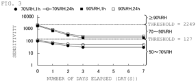
- FIG. 3 is a graph showing changes in electrostatic capacitance on a moisture absorption treatment day (0 day after moisture absorption treatment), and 1 day, 2 days, 3 days, and 7 days after the moisture absorption treatment when the superabsorbent material is used as the hygroscopic material 50.
- the frequency characteristics shown in FIG. 2 have the highest sensitivity at 1 KHz, and thus all the sensitivities described below are values of 1 KHz.
- the sensitivity is 1 or more under all hygroscopic conditions. Therefore, it can be seen that the electrostatic capacitance of the sensor unit 13 increases due to moisture absorption. In addition, the sensitivity is higher when moisture is absorbed at 90% RH than when moisture is absorbed at 70% RH, regardless of whether a moisture absorption time is 1 hour or 24 hours, until at least 7 days later.
- the humidity is maintained in a range of 50 to 70% RH when the sensitivity is in a range of 1 to 127, it is found that the humidity is maintained in a range of 70 to 90% RH when the sensitivity is in a range of 127 to 2249, and it is found that the humidity is 90% RH or more when the sensitivity is 2249 or more after the passage of at least 7 days.
- the hygroscopic material 50 is hyaluronic acid
- the hyaluronic acid sodium carboxymethyl hyaluronate is used. Since the hyaluronic acid has a binder function, the hyaluronic acid can be brought into close contact with a substrate without using an additional binder.
- the raw material paste is obtained by dissolving hyaluronic acid in water. In the same manner as described above, the raw material paste is applied onto the first electrode 51 and the second electrode 52. The raw material paste is dried at 130°C for 30 minutes.
- the initial state is the same as described above, and is a state of being left standing for 24 hours in a thermo-hygrostat (SH-641 manufactured by ESPEC CORP.) set at 25°C and 50% RH.
- FIG. 4 (A) is a graph showing changes in electrostatic capacitance on the moisture absorption treatment day (0 day after moisture absorption treatment), and 1 day, 2 days, 3 days, and 7 days after the moisture absorption treatment when hyaluronic acid is used as the hygroscopic material 50.
- the hygroscopic material 50 of hyaluronic acid has a sensitivity of 1 or more under all hygroscopic conditions. Therefore, the electrostatic capacitance of the hygroscopic material 50 of hyaluronic acid increases due to moisture absorption.
- the hygroscopic material 50 of hyaluronic acid has different sensitivities at 70% RH and 90% RH until two days have elapsed. Furthermore, the hygroscopic material 50 of hyaluronic acid has higher sensitivity as it absorbs moisture at high humidity for a long time.
- the humidity is maintained in the range of 50 to 70% RH when the sensitivity is in a range of 1.0 to 3.0, the humidity is maintained in the range of 70 to 90% RH when the sensitivity is in a range of 3.0 to 3.8, and the humidity is 90% RH or more when the sensitivity is 3.8 or more.
- the hygroscopic material 50 is polyoctanium.
- Polyoctanium-51 is used as polyoctanium. Since polyoctanium also has the binder function, no additional binder is required.
- the raw material paste is obtained by dissolving polyoctanium in water. In the same manner as described above, the raw material paste is applied onto the first electrode 51 and the second electrode 52. The raw material paste is dried at 130°C for 30 minutes. The initial state is the same as described above, and is a state of being left standing for 24 hours in a thermo-hygrostat (SH-641 manufactured by ESPEC CORP.) set at 25°C and 50% RH.
- FIG. 4 (B) is a graph showing changes in electrostatic capacitance on the moisture absorption treatment day (0 day after moisture absorption treatment), and 1 day, 2 days, 3 days, and 7 days after the moisture absorption treatment when polyoctanium is used as the hygroscopic material 50.
- the hygroscopic material 50 of polyoctanium has a sensitivity of 1 or more under all hygroscopic conditions until three days have elapsed. Therefore, the electrostatic capacitance of the hygroscopic material 50 of hyaluronic acid increases due to moisture absorption.
- the humidity is maintained in the range of 50 to 70% RH when the sensitivity is in a range of 1.0 to 2.3, the humidity is maintained in the range of 70 to 90% RH when the sensitivity is in a range of 2.3 to 3.3, and the humidity is 90% RH or more when the sensitivity is 3.3 or more.
- the sensitivity gradually approaches 1 from a state absorbing moisture in a low humidity for a short time, and the state returns to a state before moisture absorption.
- the hygroscopic material 50 is not only a superabsorbent material, hyaluronic acid, and polyoctanium, but also an organic material known to have a hygroscopic ability, and a similar result is obtained.
- the hygroscopic material 50 is bentonite.
- bentonite purified bentonite and silanized bentonite (end surface of bentonite having a layered structure is silanized to have hydrophobicity in part) are provided.
- binders were added in amounts of 3% by weight, 5% by weight, and 10% by weight to the purified bentonite, respectively.
- 3% by weight of silanized bentonite was added.
- the raw material paste is obtained by mixing bentonite and a binder with a solvent (Ekinen).
- the raw material paste is dried at 130°C for 10 minutes.
- the initial state is the same as described above, and is a state of being left standing for 24 hours in a thermo-hygrostat (SH-641 manufactured by ESPEC CORP.) set at 25°C and 50% RH.
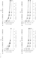
- FIGS. 5 (A), 5 (B), 5 (C), and 5 (D) are each graphs showing the changes in electrostatic capacitance on the moisture absorption treatment day (0 day after moisture absorption treatment), and 1 day, 2 days, 3 days, and 7 days after the moisture absorption treatment when purified bentonite to which 3, 5, and 10% by weight of a binder is added and silanized bentonite are used as the hygroscopic material.
- FIG. 5 (A) shows a result of adding 3% by weight of a binder to purified bentonite.
- FIG. 5 (B) shows a result of adding 5% by weight of the binder to purified bentonite.
- FIG. 5 (C) shows a result of adding 10% by weight of the binder to purified bentonite.
- FIG. 5 (D) shows a result of adding 3% by weight of the binder to silanized bentonite.
- the hygroscopic material 50 of purified bentonite has a sensitivity of 1 or more under all hygroscopic conditions. Therefore, the electrostatic capacitance of the hygroscopic material 50 of purified bentonite increases due to moisture absorption. In addition, the sensitivity is higher when moisture is absorbed at 90% RH than when moisture is absorbed at 70% RH, regardless of whether a moisture absorption time is 1 hour or 24 hours, until at least 7 days later. The hygroscopic material 50 of purified bentonite decreases in sensitivity as the amount of binder increases.
- the threshold in the case of a binder amount of 3% by weight is set to sensitivities of 1.8 and 4.7
- the threshold in the case of a binder amount of 5% by weight is set to sensitivities of 1.4 and 2.4
- the threshold in the case of a binder amount of 10% by weight is set to sensitivities of 1.3 and 1.7
- the humidity is maintained at 50 to 70% RH when the sensitivities are in ranges of 1.0 to 1.8, 1.0 to 1.4, and 1.0 to 1.3, respectively
- the humidity is maintained in the range of 70 to 90% RH when the sensitivities are in ranges of 1.8 to 4.7, 1.4 to 2.4, and 1.3 to 1.7, respectively
- the humidity is 90% RH or more when the sensitivities are 4.7, 2.4, and 1.7 or more, respectively.
- the hygroscopic material 50 of silanized bentonite has a sensitivity of 1 or more under all hygroscopic conditions. Therefore, the electrostatic capacitance of the hygroscopic material 50 of silanized bentonite increases due to moisture absorption.
- the humidity is maintained in the range of 50 to 70% RH when the sensitivity is in a range of 1.0 to 1.6, the humidity is maintained in the range of 70 to 90% RH when the sensitivity is in a range of 1.6 to 2.2, and the humidity is 90% RH or more when the sensitivity is 2.2 or more.
- the silanized bentonite Since the silanized bentonite is hydrophobized in part, water is hardly adsorbed. Thus, the silanized bentonite has low sensitivity, and once adsorbed water is easily desorbed. Therefore, the silanized bentonite has a greater decrease in sensitivity with a lapse of time than the purified bentonite.
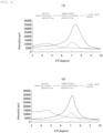
- FIGS. 6 (A) and 6 (B) are views showing changes in an X-ray diffraction (XRD) pattern before and after moisture absorption.
- XRD X-ray diffraction
- Bentonite is a layered compound, and takes up adsorbed water between layers. Therefore, the peak of an X-ray diffraction pattern of bentonite shifts due to moisture absorption. As shown in FIG. 6 (A) , it can be confirmed that a peak position of purified bentonite shifts not only immediately after moisture absorption but also when nine days have passed after moisture absorption. That is, the purified bentonite takes up water between the layers when nine days have passed after moisture absorption.
- the hygroscopic material is not limited to silanized bentonite and purified bentonite, and the same result as this time can be obtained as long as it is a layered compound having a hygroscopic ability.
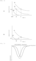
- FIG. 7 is a view showing a relationship between the moisture absorption amount and various conditions.
- the hygroscopic material absorbs moisture in the atmosphere
- a time change curve indicating how much water is adsorbed with a lapse of time at a certain constant humidity as shown in the center graph of FIG. 7 .
- the electrostatic capacitance can be a generalized parameter as the moisture absorption amount including both these humidities and time.
- the measuring instrument 30 can estimate the change in the moisture absorption amount (V1 - V0) at T time by obtaining a relationship between the moisture absorption amount and the electrostatic capacitance in advance to detect the change in electrostatic capacitance (C1 - C0) from a certain arbitrary time T0 to a time T1 after the T time.
- the moisture absorption amount measurement system 1 can obtain the moisture absorption amount from a measurement start time point to a measurement end time point regardless of how a certain measurement object has been stored so far when trying to find out in what environment the measurement object has been stored.
- the sensor unit 13 of the present embodiment can detect humidity by measuring whether or not the humidity has reached a certain level or more only with the hygroscopic material 50, the first electrode 51, the second electrode 52, and the substrate on which these are installed. Unlike a general humidity sensor, the sensor unit 13 of the present embodiment records a history of past humidity changes not in an external memory but in the hygroscopic material. Therefore, the sensor unit 13 can know the history of past humidity changes while being non-powered.
- FIGS. 9 (A) and 9 (B) are views showing a film thickness of the hygroscopic material 50 and the sensitivity of the sensor unit 13 when the superabsorbent material is used as the hygroscopic material 50.
- FIG. 9 (A) is a graph showing a change in sensitivity after moisture absorption at 90% RH for 24 hours
- FIG. 9 (B) is a graph showing the change in sensitivity after moisture absorption at 70% RH for 24 hours.
- the threshold of the humidity to be detected can be controlled by changing the film thickness of the hygroscopic material, such as for detecting low humidity when the film thickness of the hygroscopic material 50 is thick and for detecting high humidity when the film thickness is thin.
- the film thickness of the hygroscopic material 50 is 1.5 mm
- the sensitivity when moisture is absorbed at 90% RH is about 8752
- the sensitivity when moisture is absorbed at 70% RH is about 635. Both show very high sensitivity. Therefore, when the film thickness of the hygroscopic material 50 is large, measurement can be performed with high sensitivity at low humidity.
- the sensitivity when moisture is absorbed at 90% RH is about 86
- the sensitivity when moisture is absorbed at 70% RH is about 8. That is, when the film thickness of the hygroscopic material 50 is thin, the sensitivity is significantly lowered.
- the sensor unit 13 responds only to high humidity.
- the sensor unit 13 of the present embodiment can be a sensor that reacts from low humidity to high humidity or a sensor that reacts only at high humidity by adjusting the film thickness of the hygroscopic material. That is, a detectable threshold can be easily controlled by changing the film thickness of the hygroscopic material 50.
- the sensor unit 13 includes a first humidity sensor and a second humidity sensor having different amounts of change in electrical characteristics according to the moisture absorption amount.
- FIGS. 10 (A) and 10 (B) are views showing the change in sensitivity when the hygroscopic material 50 is formed of a composite material of the superabsorbent material and the purified bentonite.
- FIG. 10 (A) shows a case where a weight ratio of the superabsorbent material and the purified bentonite is 1 : 1
- FIG. 10 (B) shows a case where the weight ratio of the superabsorbent material and the purified bentonite is 9 : 1.
- An addition amount of the binder is 3% by weight in both cases.
- the superabsorbent material has very high sensitivity, and has a large change in sensitivity with a lapse of time.
- a sensitivity decrease when seven days have passed is about 88%.
- purified bentonite has a relatively low sensitivity, and has a small change in sensitivity with a lapse of time.
- the sensitivity decrease when seven days have passed is about 58%. Therefore, the sensor unit 13 can control the sensitivity and water retention time by using a material obtained by mixing a material having high sensitivity and short water retention time with a material having low sensitivity and long water retention time.
- the sensitivity decreases as a proportion of purified bentonite increases, while the decrease in sensitivity with a lapse of time decreases.
- the weight ratio of the purified bentonite to the superabsorbent material is 1 : 1
- the change in sensitivity after seven days have elapsed when moisture is absorbed at 90% RH for 24 hours is about 86%
- the weight ratio is 9 : 1
- the change in sensitivity is about 60%.
- FIGS. 11 (A) to 11 (D) are views showing the change in sensitivity when the hygroscopic material 50 is formed of a composite material of hyaluronic acid and purified bentonite.
- FIG. 11 (A) shows a case where a weight ratio of hyaluronic acid and purified bentonite is 10 : 0,
- FIG. 11 (B) shows a case where the weight ratio of hyaluronic acid and purified bentonite is 8 : 2
- FIG. 11 (C) shows a case where the weight ratio of hyaluronic acid and purified bentonite is 5 : 5
- FIG. 11 (D) shows a case where the weight ratio of hyaluronic acid and purified bentonite is 2 : 8.
- hyaluronic acid has hygroscopicity and also functions as a binder. Therefore, the composite material of hyaluronic acid and purified bentonite does not require a binder having low hygroscopicity. Thus, by mixing hyaluronic acid, the sensitivity can be improved without adding a binder.
- polyoctanium also has hygroscopicity and functions as a binder.
- any material that has hygroscopicity and also functions as a binder may be used.
- the sensor unit 13 described above can detect whether or not it is exposed under a humidity environment of a certain level or more, and cannot detect an exposure timing. For example, the same sensitivity may be shown between a case where measurement is performed immediately after moisture absorption at low humidity and a case where measurement is performed after a lapse of a certain period of time at high humidity. On the other hand, the array sensor can detect the timing of exposure to the humidity environment of a certain level or more.
- FIGS. 12 (A) and 12 (B) are views showing the changes in sensitivity with a lapse of time in the plurality of the sensor units 13 constituting the array sensor.
- the sensor unit 13 having high sensitivity is relatively thick, for example, and the sensor unit 13 having low sensitivity is relatively thin.
- the hygroscopic material 50 having high sensitivity such as a superabsorbent material may be used for the high-sensitivity sensor unit 13
- the hygroscopic material 50 having low sensitivity such as hyaluronic acid may be used for the low-sensitivity sensor unit 13.
- FIG. 12 (A) shows the change in sensitivity of the high-sensitivity sensor unit 13
- FIG. 12 (B) shows the change in sensitivity of the low-sensitivity sensor unit 13.
- H1, H2, and H3 each correspond to humidity, and the humidity of H1 is the highest and is 100% RH.
- the low-sensitivity sensor unit 13 shown in FIG. 12 (B) has a sensitivity of 1.0 or less after the time t2 elapses under the environment of the humidity H2, and does not exhibit a response. Under the environment of the humidity H3, no response is exhibited immediately after moisture absorption.
- the sensitivity shows a value larger than 1 until a certain time after the time t2 has elapsed.
- the sensor unit 13 indicates sensitivity Kx.
- the sensitivity K1 is shown in a high-sensitivity sensor
- the sensitivity Kx is shown in a low-sensitivity sensor.
- the array sensor by obtaining in advance a relationship (curves of H1 and H2 shown in the drawing) between the humidity and an elapsed time after moisture absorption with respect to the sensitivity in each of the high-sensitivity sensor unit 13 and the low-sensitivity sensor unit 13, it is possible to detect both the humidity and the elapsed time from a combination of the sensitivity K1 of the high-sensitivity sensor unit 13 and the sensitivity Kx of the low-sensitivity sensor unit 13 actually measured.
- a humidity range that can be measured including the elapsed time after moisture absorption is in a range of H2 to H1.
- the sensor unit 13 having higher sensitivity may be used as a low-sensitivity sensor.
- the first moisture absorbing sensor and the second moisture absorbing sensor having different sensitivities are used.
- humidity detection including a lapse of time may be performed with higher accuracy using a larger number of moisture absorbing sensors.
- the change in electrostatic capacitance has been described as sensitivity.
- the measuring instrument 30 does not need to measure the electrostatic capacitance value, and may read an impedance change as described below.
- FIG. 13 is a view for explaining a humidity detection principle.
- the impedance has a maximum value at the resonance frequency f.
- the resonance frequency f when the hygroscopic material 50 absorbs moisture and the capacitance component C changes, the resonance frequency f also changes, and the impedance also changes.
- the IC 11 reads the change in impedance and transmits the impedance change to the measuring instrument 30. If a relationship between the impedance and the hygroscopic condition is measured in advance, the measuring instrument 30 can detect whether or not it is exposed under the humidity environment exceeding a threshold.
- the sensitivity change of the hygroscopic material shown in the present embodiment is shown in Table 1 below.
- the change (%) shown in Table 1 is 100% when the sensitivity is 1. That is, when returning to the state before moisture absorption, the change is 100%.
- the change is (2249.0 -265.3)/(2249.0 -1.0) ⁇ 100 ⁇ 88.3 (%).
- any of the materials shown in the present embodiment is a hygroscopic material that maintains a hygroscopic state for a predetermined time or more after moisture absorption.
- the example in which the electrical characteristics return by 92% with the material having the largest change has been described; however, maintaining the hygroscopic state means that the state does not return to the state before moisture absorption (the change does not become 100%).
- the moisture absorbing sensor is not limited to the RFID tag.
- the measuring instrument 30 and the sensor unit 13 may be connected by wire to measure the electrical characteristics such as electrostatic capacitance.
- a change in electric resistance or a change in inductance may be measured instead of the change in electrostatic capacitance due to moisture absorption.
Landscapes
- Chemical & Material Sciences (AREA)
- Engineering & Computer Science (AREA)
- Physics & Mathematics (AREA)
- General Physics & Mathematics (AREA)
- Chemical Kinetics & Catalysis (AREA)
- General Health & Medical Sciences (AREA)
- Pathology (AREA)
- Immunology (AREA)
- Biochemistry (AREA)
- Electrochemistry (AREA)
- Health & Medical Sciences (AREA)
- Life Sciences & Earth Sciences (AREA)
- Analytical Chemistry (AREA)
- Microelectronics & Electronic Packaging (AREA)
- Computer Hardware Design (AREA)
- Theoretical Computer Science (AREA)
- Computer Networks & Wireless Communication (AREA)
- Investigating Or Analyzing Materials By The Use Of Electric Means (AREA)
Abstract
Description
- The present invention relates to a moisture absorbing sensor, an RFID tag including the moisture absorbing sensor, and a moisture absorption amount measurement system.
- Conventionally, a method of monitoring a temporal change in humidity using a humidity sensor when an article sensitive to humidity in the atmosphere is stored or transported is known. The conventional method includes a general humidity sensor, a circuit that operates the humidity sensor, and a device for recording and analyzing information. Therefore, this conventional method becomes a complicated system and is costly. When a battery is used as a power source, it is necessary to periodically replace the battery.
- Thus, a humidity indicator that does not use a power source is known. The humidity indicator is obtained by impregnating paper with a material whose color changes depending on humidity. The humidity indicator can know a humidity state by changing the color. However, the humidity indicator needs to visually confirm a color state. Therefore, the humidity indicator is difficult to perform confirmation operation when the number of articles to be measured increases.
- Thus, for example,
Patent Documents -
Patent Document 1 discloses that exposure to a certain level or more of environment for a certain period of time or more is detected by utilizing the fact that interface resistance between aluminum and aluminum oxide irreversibly changes due to environment, temperature, humidity, or atmospheric gas. -
Patent Document 2 discloses that a deliquescent material such as calcium chloride is used for a moisture sensitive material. The deliquescent material ofPatent Document 2 becomes a liquid state when an environmental humidity becomes equal to or higher than a certain level. Therefore, the electrical characteristics of a circuit containing the deliquescent material change. In the configuration ofPatent Document 2, whether the environmental humidity is equal to or higher than a certain threshold value can be measured by measuring the change in the electrical characteristics. -
- Patent Document 1:
Japanese Patent Application Laid-Open No. 2009-36526 - Patent Document 2:
Japanese Patent Application Laid-Open No. 2007-333484 - Since the configuration of
Patent Document 1 detects a change in environment according to a degree of oxidation, when it is desired to detect whether humidity exceeds a certain threshold, the threshold cannot be freely set. - The moisture sensitive material of
Patent Document 2 cannot maintain its shape after moisture absorption. Thus, a material for absorbing the moisture sensitive material liquefied is separately required. In addition, the configuration ofPatent Document 2 also does not allow the threshold of humidity desired to be detected to be freely set. - Thus, an object of the present invention is to provide a humidity sensor and a moisture absorption amount measurement system capable of freely setting a threshold of humidity desired to be detected.
- A moisture absorbing sensor according to the present invention includes: a hygroscopic material that maintains a shape before and after moisture absorption and maintains a hygroscopic state for a predetermined time or more after moisture absorption; and an electrode disposed in the hygroscopic material, in which an electrical characteristic of a circuit formed by the electrode and the hygroscopic material changes according to a moisture absorption amount of the hygroscopic material.
- Since the hygroscopic material can maintain a shape before and after moisture absorption, it is not necessary to separately provide a material for absorbing the hygroscopic material as in
Patent Document 2. In addition, since the shape of the hygroscopic material is maintained, an amount of change in electrical characteristics with respect to the moisture absorption amount can be easily controlled by changing the thickness, the type of material, or the like. Therefore, the moisture absorbing sensor of the present invention can freely set a threshold of humidity desired to be detected. Maintaining a shape means maintaining a solid state, and is included in the concept of maintaining the shape when there is a change in volume due to moisture absorption. - According to the present invention, it is possible to freely set a threshold of humidity desired to be detected.
-
-
FIG. 1 (A) is a block diagram showing a configuration of a moisture absorptionamount measurement system 1, andFIG. 1 (B) is a partial external perspective view of asensor unit 13 in anRFID tag 10. -
FIG. 2 is a graph showing a delay (tan δ) in electrostatic capacitance and current phase when moisture is absorbed at 90% RH for 24 hours when a superabsorbent material is used as ahygroscopic material 50. -
FIG. 3 is a graph showing changes in electrostatic capacitance on a moisture absorption treatment day (0 day after moisture absorption treatment), and 1 day, 2 days, 3 days, and 7 days after the moisture absorption treatment when the superabsorbent material is used as thehygroscopic material 50. -
FIGS. 4 (A) and 4 (B) are each graphs showing the changes in electrostatic capacitance on the moisture absorption treatment day (0 day after moisture absorption treatment), and 1 day, 2 days, 3 days, and 7 days after the moisture absorption treatment when hyaluronic acid and polyoctanium are used as thehygroscopic material 50. -
FIGS. 5 (A), 5 (B), 5 (C), and 5 (D) are each graphs showing the changes in electrostatic capacitance on the moisture absorption treatment day (0 day after moisture absorption treatment), and 1 day, 2 days, 3 days, and 7 days after the moisture absorption treatment when purified bentonite to which 3, 5, and 10% by weight of a binder is added and silanized bentonite are used as thehygroscopic material 50. -
FIGS. 6 (A) and 6 (B) are each views showing changes in X-ray diffraction (XRD) patterns before and after moisture absorption in the purified bentonite and the silanized bentonite. -
FIG. 7 is a view showing a relationship between a moisture absorption amount and various conditions. -
FIG. 8 is a view showing a relationship between the moisture absorption amount and the electrostatic capacitance. -
FIGS. 9 (A) and 9 (B) are views showing a thickness of thehygroscopic material 50 and sensitivity of thesensor unit 13 when the superabsorbent material is used as thehygroscopic material 50. -
FIGS. 10 (A) and 10 (B) are views showing a change in sensitivity when thehygroscopic material 50 is formed of a composite material of the superabsorbent material and the purified bentonite. -
FIGS. 11 (A) to 11 (D) are views showing the change in sensitivity when thehygroscopic material 50 is formed of a composite material of hyaluronic acid and the purified bentonite. -
FIGS. 12 (A) and 12 (B) are views showing the changes in sensitivity with a lapse of time in a plurality of thesensor units 13 constituting an array sensor. -
FIG. 13 is a view for explaining a humidity detection principle. -
FIG. 1 (A) is a block diagram showing a configuration of a moisture absorptionamount measurement system 1, andFIG. 1 (B) is an external perspective view of asensor unit 13 in anRFID tag 10. - The moisture absorption
amount measurement system 1 includes theRFID tag 10 and ameasuring instrument 30. TheRFID tag 10 includes anIC 11, anantenna 12, and thesensor unit 13. TheIC 11, theantenna 12, and thesensor unit 13 are arranged on a substrate such as a PET film (not shown). TheRFID tag 10 is attached to an article, a box for packing the article, or the like. - The
measuring instrument 30 is an RFID reader. Themeasuring instrument 30 includes an antenna (not shown) and communicates with theRFID tag 10. - The
IC 11 of theRFID tag 10 receives power from themeasuring instrument 30 via theantenna 12 and communicates with themeasuring instrument 30. The IC 11 is connected to thesensor unit 13. In accordance with an instruction from themeasuring instrument 30, theIC 11 reads information indicating electrical characteristics of thesensor unit 13 and transmits the read information to themeasuring instrument 30. - As shown in
FIG. 1 (B) , thesensor unit 13 includes ahygroscopic material 50, and afirst electrode 51 and asecond electrode 52 arranged on thehygroscopic material 50. - The
first electrode 51 and thesecond electrode 52 are arranged in a comb shape as an example. As an example, the first electrode and thesecond electrode 52 are formed by arranging six thin electrodes each having a width D of 50 um. A gap G between the electrodes is 50 um. A length L of the electrode is 1 mm. However, the number, width, gap, and length of the electrodes are not limited to this example. In addition, the structure of the electrode is not limited to the comb-shaped structure, and may be any structure as long as electrostatic capacitance is generated. - The
hygroscopic material 50 is formed of, for example, a superabsorbent material of an acrylic acid polymer partial sodium salt crosslinked product. Thehygroscopic material 50 absorbs moisture in the air and holds the moisture for a long time. The thickness of thehygroscopic material 50 is, for example, 0.71 mm. A dielectric constant of thehygroscopic material 50 changes according to an amount of absorbed moisture (moisture absorption amount). Therefore, the electrical characteristics of a circuit formed by thehygroscopic material 50, thefirst electrode 51, and thesecond electrode 52 change depending on the moisture absorption amount of thehygroscopic material 50. In particular, in the example ofFIG. 1 (B) , since thefirst electrode 51 and thesecond electrode 52 are arranged in a comb shape, the electrostatic capacitance changes depending on the moisture absorption amount of thehygroscopic material 50. - The measuring
instrument 30 estimates the moisture absorption amount of thehygroscopic material 50 by measuring the change in electrostatic capacitance. As a result, the moisture absorptionamount measurement system 1 can detect whether or not an article to which theRFID tag 10 is attached is exposed under a humidity environment exceeding a specific threshold. Hereinafter, the present invention will be specifically described. - First, a case where the superabsorbent material is used for the
hygroscopic material 50 will be described. The superabsorbent material uses an acrylic acid polymer partial sodium salt crosslinked product. In thehygroscopic material 50 of the superabsorbent material, in order to bond particles of the superabsorbent material to each other and a raw material paste of thehygroscopic material 50 to the substrate, a binder was added in an amount of 3% by weight to the superabsorbent material. The superabsorbent material, the binder, and a solvent (Ekinen) were mixed to prepare a raw material paste. - Each of the
first electrode 51 and thesecond electrode 52 shown inFIG. 1 (B) is formed of a silver paste printed on a PET film. The silver paste is dried at 130°C for 10 minutes. The raw material paste is applied onto the driedfirst electrode 51 andsecond electrode 52. The raw material paste is further dried at 130°C for 10 minutes. Thus, thesensor unit 13 is produced. - The
sensor unit 13 was left standing for 24 hours in a thermo-hygrostat (SH-641 manufactured by ESPEC CORP.) set at 25°C and 50% RH. This state is referred to as an initial state before moisture absorption. - Thereafter, the
sensor unit 13 in the initial state is stored at 70% RH or 90% RH for 1 hour or 24 hours in the same type of thermo-hygrostat as described above. Thus, thesensor unit 13 absorbs moisture. -
FIG. 2 is a graph showing a delay (tan δ) in electrostatic capacitance and current phase when moisture is absorbed at 90% RH for 24 hours. The electrostatic capacitance was measured with an LCR meter (E4980A manufactured by Keysight Technologies). A measurement frequency is 1 KHz to 1 MHz. The change in electrostatic capacitance (hereinafter referred to as sensitivity) shown inFIG. 2 is a value obtained by dividing the electrostatic capacitance value after moisture absorption by the electrostatic capacitance value before moisture absorption. - As shown in
FIG. 2 , the lower the frequency, the higher the sensitivity. Such frequency characteristics correspond to dispersion behavior due to orientation polarization of water. The change in electrostatic capacitance due to moisture absorption indicates that the change is caused by moisture absorption of water in the air by thehygroscopic material 50. -
FIG. 3 is a graph showing changes in electrostatic capacitance on a moisture absorption treatment day (0 day after moisture absorption treatment), and 1 day, 2 days, 3 days, and 7 days after the moisture absorption treatment when the superabsorbent material is used as thehygroscopic material 50. The frequency characteristics shown inFIG. 2 have the highest sensitivity at 1 KHz, and thus all the sensitivities described below are values of 1 KHz. - As shown in
FIG. 3 , the sensitivity is 1 or more under all hygroscopic conditions. Therefore, it can be seen that the electrostatic capacitance of thesensor unit 13 increases due to moisture absorption. In addition, the sensitivity is higher when moisture is absorbed at 90% RH than when moisture is absorbed at 70% RH, regardless of whether a moisture absorption time is 1 hour or 24 hours, until at least 7 days later. - From these results, in the measuring
instrument 30, for example, when a threshold is set to sensitivities of 127 and 2249, it is found that the humidity is maintained in a range of 50 to 70% RH when the sensitivity is in a range of 1 to 127, it is found that the humidity is maintained in a range of 70 to 90% RH when the sensitivity is in a range of 127 to 2249, and it is found that the humidity is 90% RH or more when the sensitivity is 2249 or more after the passage of at least 7 days. - Next, an example in which the
hygroscopic material 50 is hyaluronic acid will be described. As the hyaluronic acid, sodium carboxymethyl hyaluronate is used. Since the hyaluronic acid has a binder function, the hyaluronic acid can be brought into close contact with a substrate without using an additional binder. The raw material paste is obtained by dissolving hyaluronic acid in water. In the same manner as described above, the raw material paste is applied onto thefirst electrode 51 and thesecond electrode 52. The raw material paste is dried at 130°C for 30 minutes. The initial state is the same as described above, and is a state of being left standing for 24 hours in a thermo-hygrostat (SH-641 manufactured by ESPEC CORP.) set at 25°C and 50% RH. -
FIG. 4 (A) is a graph showing changes in electrostatic capacitance on the moisture absorption treatment day (0 day after moisture absorption treatment), and 1 day, 2 days, 3 days, and 7 days after the moisture absorption treatment when hyaluronic acid is used as thehygroscopic material 50. - As shown in
FIG. 4 (A) , thehygroscopic material 50 of hyaluronic acid has a sensitivity of 1 or more under all hygroscopic conditions. Therefore, the electrostatic capacitance of thehygroscopic material 50 of hyaluronic acid increases due to moisture absorption. - The
hygroscopic material 50 of hyaluronic acid has different sensitivities at 70% RH and 90% RH until two days have elapsed. Furthermore, thehygroscopic material 50 of hyaluronic acid has higher sensitivity as it absorbs moisture at high humidity for a long time. Thus, in the measuringinstrument 30, for example, when the threshold is set to sensitivities of 3.0 and 3.8, it is found that on the moisture absorption treatment day, the humidity is maintained in the range of 50 to 70% RH when the sensitivity is in a range of 1.0 to 3.0, the humidity is maintained in the range of 70 to 90% RH when the sensitivity is in a range of 3.0 to 3.8, and the humidity is 90% RH or more when the sensitivity is 3.8 or more. - An example in which the
hygroscopic material 50 is polyoctanium will be described. Polyoctanium-51 is used as polyoctanium. Since polyoctanium also has the binder function, no additional binder is required. The raw material paste is obtained by dissolving polyoctanium in water. In the same manner as described above, the raw material paste is applied onto thefirst electrode 51 and thesecond electrode 52. The raw material paste is dried at 130°C for 30 minutes. The initial state is the same as described above, and is a state of being left standing for 24 hours in a thermo-hygrostat (SH-641 manufactured by ESPEC CORP.) set at 25°C and 50% RH. -
FIG. 4 (B) is a graph showing changes in electrostatic capacitance on the moisture absorption treatment day (0 day after moisture absorption treatment), and 1 day, 2 days, 3 days, and 7 days after the moisture absorption treatment when polyoctanium is used as thehygroscopic material 50. - As shown in
FIG. 4 (B) , thehygroscopic material 50 of polyoctanium has a sensitivity of 1 or more under all hygroscopic conditions until three days have elapsed. Therefore, the electrostatic capacitance of thehygroscopic material 50 of hyaluronic acid increases due to moisture absorption. - In a case where polyoctanium is used as the
hygroscopic material 50, in the measuringinstrument 30, for example, when the threshold is set to sensitivities of 2.3 and 3.3, it is found that on the moisture absorption treatment day, the humidity is maintained in the range of 50 to 70% RH when the sensitivity is in a range of 1.0 to 2.3, the humidity is maintained in the range of 70 to 90% RH when the sensitivity is in a range of 2.3 to 3.3, and the humidity is 90% RH or more when the sensitivity is 3.3 or more. On the other hand, it can be seen that in thehygroscopic material 50 of polyoctanium, when more than three days have passed, the sensitivity gradually approaches 1 from a state absorbing moisture in a low humidity for a short time, and the state returns to a state before moisture absorption. - The
hygroscopic material 50 is not only a superabsorbent material, hyaluronic acid, and polyoctanium, but also an organic material known to have a hygroscopic ability, and a similar result is obtained. - Next, an example in which the
hygroscopic material 50 is bentonite will be described. As the bentonite, purified bentonite and silanized bentonite (end surface of bentonite having a layered structure is silanized to have hydrophobicity in part) are provided. - In the
hygroscopic material 50 of the bentonite, in order to bond particles of the bentonite to each other and a raw material paste of thehygroscopic material 50 to the substrate, binders were added in amounts of 3% by weight, 5% by weight, and 10% by weight to the purified bentonite, respectively. In addition, 3% by weight of silanized bentonite was added. The raw material paste is obtained by mixing bentonite and a binder with a solvent (Ekinen). Similarly to the case of using the superabsorbent material as thehygroscopic material 50, the raw material paste is dried at 130°C for 10 minutes. The initial state is the same as described above, and is a state of being left standing for 24 hours in a thermo-hygrostat (SH-641 manufactured by ESPEC CORP.) set at 25°C and 50% RH. -
FIGS. 5 (A), 5 (B), 5 (C), and 5 (D) are each graphs showing the changes in electrostatic capacitance on the moisture absorption treatment day (0 day after moisture absorption treatment), and 1 day, 2 days, 3 days, and 7 days after the moisture absorption treatment when purified bentonite to which 3, 5, and 10% by weight of a binder is added and silanized bentonite are used as the hygroscopic material. -
FIG. 5 (A) shows a result of adding 3% by weight of a binder to purified bentonite.FIG. 5 (B) shows a result of adding 5% by weight of the binder to purified bentonite.FIG. 5 (C) shows a result of adding 10% by weight of the binder to purified bentonite.FIG. 5 (D) shows a result of adding 3% by weight of the binder to silanized bentonite. - As shown in
FIGS. 5 (A) to 5 (C) , thehygroscopic material 50 of purified bentonite has a sensitivity of 1 or more under all hygroscopic conditions. Therefore, the electrostatic capacitance of thehygroscopic material 50 of purified bentonite increases due to moisture absorption. In addition, the sensitivity is higher when moisture is absorbed at 90% RH than when moisture is absorbed at 70% RH, regardless of whether a moisture absorption time is 1 hour or 24 hours, until at least 7 days later. Thehygroscopic material 50 of purified bentonite decreases in sensitivity as the amount of binder increases. - Thus, in the measuring
instrument 30, for example, when the threshold in the case of a binder amount of 3% by weight is set to sensitivities of 1.8 and 4.7, the threshold in the case of a binder amount of 5% by weight is set to sensitivities of 1.4 and 2.4, and the threshold in the case of a binder amount of 10% by weight is set to sensitivities of 1.3 and 1.7, it is found that after the passage of at least 7 days, the humidity is maintained at 50 to 70% RH when the sensitivities are in ranges of 1.0 to 1.8, 1.0 to 1.4, and 1.0 to 1.3, respectively, the humidity is maintained in the range of 70 to 90% RH when the sensitivities are in ranges of 1.8 to 4.7, 1.4 to 2.4, and 1.3 to 1.7, respectively, and the humidity is 90% RH or more when the sensitivities are 4.7, 2.4, and 1.7 or more, respectively. - As shown in
FIG. 5 (D) , thehygroscopic material 50 of silanized bentonite has a sensitivity of 1 or more under all hygroscopic conditions. Therefore, the electrostatic capacitance of thehygroscopic material 50 of silanized bentonite increases due to moisture absorption. In the measuringinstrument 30, for example, when the threshold is set to sensitivities of 1.6 and 2.2, it is found that on the moisture absorption treatment day, the humidity is maintained in the range of 50 to 70% RH when the sensitivity is in a range of 1.0 to 1.6, the humidity is maintained in the range of 70 to 90% RH when the sensitivity is in a range of 1.6 to 2.2, and the humidity is 90% RH or more when the sensitivity is 2.2 or more. - Since the silanized bentonite is hydrophobized in part, water is hardly adsorbed. Thus, the silanized bentonite has low sensitivity, and once adsorbed water is easily desorbed. Therefore, the silanized bentonite has a greater decrease in sensitivity with a lapse of time than the purified bentonite.
-
FIGS. 6 (A) and 6 (B) are views showing changes in an X-ray diffraction (XRD) pattern before and after moisture absorption. For the XRD measurement, Miniflex 600 manufactured by Rigaku Corporation was used. The measurement was performed in a range of 2θ = 3° to 10° under conditions of a step of 0.01° and a scan speed of 10°/minute. - Bentonite is a layered compound, and takes up adsorbed water between layers. Therefore, the peak of an X-ray diffraction pattern of bentonite shifts due to moisture absorption. As shown in
FIG. 6 (A) , it can be confirmed that a peak position of purified bentonite shifts not only immediately after moisture absorption but also when nine days have passed after moisture absorption. That is, the purified bentonite takes up water between the layers when nine days have passed after moisture absorption. - On the other hand, as shown in
FIG. 6 (B) , in the silanized bentonite, the peak position immediately after moisture absorption shifts (water is taken up between layers); however, the peak position almost returns to the peak position before moisture absorption when nine days have passed after moisture absorption. That is, in the silanized bentonite, absorbed moisture is almost desorbed from between the layers when nine days have passed. From these results, it is considered that in the same layered compound, when the hydrophilicity is high, the sensitivity is high, and water can be continuously taken up between the layers after moisture absorption. - The hygroscopic material is not limited to silanized bentonite and purified bentonite, and the same result as this time can be obtained as long as it is a layered compound having a hygroscopic ability.
- Next,
FIG. 7 is a view showing a relationship between the moisture absorption amount and various conditions. When the hygroscopic material absorbs moisture in the atmosphere, there are an isothermal adsorption curve indicating how much water is adsorbed at each humidity as shown in the left graph ofFIG. 7 , and a time change curve indicating how much water is adsorbed with a lapse of time at a certain constant humidity as shown in the center graph ofFIG. 7 . As shown in the right graph ofFIG. 7 , the electrostatic capacitance can be a generalized parameter as the moisture absorption amount including both these humidities and time. - Thus, as shown in
FIG. 8 , the measuringinstrument 30 can estimate the change in the moisture absorption amount (V1 - V0) at T time by obtaining a relationship between the moisture absorption amount and the electrostatic capacitance in advance to detect the change in electrostatic capacitance (C1 - C0) from a certain arbitrary time T0 to a time T1 after the T time. - As a result, the moisture absorption
amount measurement system 1 can obtain the moisture absorption amount from a measurement start time point to a measurement end time point regardless of how a certain measurement object has been stored so far when trying to find out in what environment the measurement object has been stored. - As described above, the
sensor unit 13 of the present embodiment can detect humidity by measuring whether or not the humidity has reached a certain level or more only with thehygroscopic material 50, thefirst electrode 51, thesecond electrode 52, and the substrate on which these are installed. Unlike a general humidity sensor, thesensor unit 13 of the present embodiment records a history of past humidity changes not in an external memory but in the hygroscopic material. Therefore, thesensor unit 13 can know the history of past humidity changes while being non-powered. - In the
sensor unit 13 of the present embodiment, the sensitivity can be easily adjusted by changing the thickness of thehygroscopic material 50. Next,FIGS. 9 (A) and 9 (B) are views showing a film thickness of thehygroscopic material 50 and the sensitivity of thesensor unit 13 when the superabsorbent material is used as thehygroscopic material 50.FIG. 9 (A) is a graph showing a change in sensitivity after moisture absorption at 90% RH for 24 hours, andFIG. 9 (B) is a graph showing the change in sensitivity after moisture absorption at 70% RH for 24 hours. - As shown in
FIGS. 9 (A) and 9 (B) , the larger the film thickness of thehygroscopic material 50, the higher the sensitivity can be obtained at low humidity. Thus, the threshold of the humidity to be detected can be controlled by changing the film thickness of the hygroscopic material, such as for detecting low humidity when the film thickness of thehygroscopic material 50 is thick and for detecting high humidity when the film thickness is thin. - For example, when the film thickness of the
hygroscopic material 50 is 1.5 mm, the sensitivity when moisture is absorbed at 90% RH is about 8752, and the sensitivity when moisture is absorbed at 70% RH is about 635. Both show very high sensitivity. Therefore, when the film thickness of thehygroscopic material 50 is large, measurement can be performed with high sensitivity at low humidity. - On the other hand, when the film thickness of the
hygroscopic material 50 is 0.4 mm, the sensitivity when moisture is absorbed at 90% RH is about 86, and the sensitivity when moisture is absorbed at 70% RH is about 8. That is, when the film thickness of thehygroscopic material 50 is thin, the sensitivity is significantly lowered. When the film thickness of thehygroscopic material 50 is thin, thesensor unit 13 responds only to high humidity. - Therefore, the
sensor unit 13 of the present embodiment can be a sensor that reacts from low humidity to high humidity or a sensor that reacts only at high humidity by adjusting the film thickness of the hygroscopic material. That is, a detectable threshold can be easily controlled by changing the film thickness of thehygroscopic material 50. - Next, an example will be described in which the
sensor unit 13 includes a first humidity sensor and a second humidity sensor having different amounts of change in electrical characteristics according to the moisture absorption amount. -
FIGS. 10 (A) and 10 (B) are views showing the change in sensitivity when thehygroscopic material 50 is formed of a composite material of the superabsorbent material and the purified bentonite.FIG. 10 (A) shows a case where a weight ratio of the superabsorbent material and the purified bentonite is 1 : 1, andFIG. 10 (B) shows a case where the weight ratio of the superabsorbent material and the purified bentonite is 9 : 1. An addition amount of the binder is 3% by weight in both cases. - As shown in
FIG. 3 , the superabsorbent material has very high sensitivity, and has a large change in sensitivity with a lapse of time. When moisture is absorbed at 90% RH for 24 hours, a sensitivity decrease when seven days have passed is about 88%. On the other hand, as shown inFIG. 5 (A) , purified bentonite has a relatively low sensitivity, and has a small change in sensitivity with a lapse of time. When moisture is absorbed at 90% RH for 24 hours, the sensitivity decrease when seven days have passed is about 58%. Therefore, thesensor unit 13 can control the sensitivity and water retention time by using a material obtained by mixing a material having high sensitivity and short water retention time with a material having low sensitivity and long water retention time. - As shown in
FIGS. 10 (A) and 10 (B) , the sensitivity decreases as a proportion of purified bentonite increases, while the decrease in sensitivity with a lapse of time decreases. For example, when the weight ratio of the purified bentonite to the superabsorbent material is 1 : 1, the change in sensitivity after seven days have elapsed when moisture is absorbed at 90% RH for 24 hours is about 86%, and when the weight ratio is 9 : 1, the change in sensitivity is about 60%. -
FIGS. 11 (A) to 11 (D) are views showing the change in sensitivity when thehygroscopic material 50 is formed of a composite material of hyaluronic acid and purified bentonite.FIG. 11 (A) shows a case where a weight ratio of hyaluronic acid and purified bentonite is 10 : 0,FIG. 11 (B) shows a case where the weight ratio of hyaluronic acid and purified bentonite is 8 : 2,FIG. 11 (C) shows a case where the weight ratio of hyaluronic acid and purified bentonite is 5 : 5, andFIG. 11 (D) shows a case where the weight ratio of hyaluronic acid and purified bentonite is 2 : 8. - From these results, the sensitivity is improved as the proportion of purified bentonite increases. These results are higher than the sensitivity when 3% by weight of the binder is added to purified bentonite shown in
FIG. 5 (A) . - As described above, hyaluronic acid has hygroscopicity and also functions as a binder. Therefore, the composite material of hyaluronic acid and purified bentonite does not require a binder having low hygroscopicity. Thus, by mixing hyaluronic acid, the sensitivity can be improved without adding a binder.
- In addition to hyaluronic acid, polyoctanium also has hygroscopicity and functions as a binder. In addition, any material that has hygroscopicity and also functions as a binder may be used.
- Next, an array sensor in which a plurality of the
sensor units 13 having different changes in electrical characteristics (that is, sensitivities) with respect to the moisture absorption amount are combined will be described. - The
sensor unit 13 described above can detect whether or not it is exposed under a humidity environment of a certain level or more, and cannot detect an exposure timing. For example, the same sensitivity may be shown between a case where measurement is performed immediately after moisture absorption at low humidity and a case where measurement is performed after a lapse of a certain period of time at high humidity. On the other hand, the array sensor can detect the timing of exposure to the humidity environment of a certain level or more. -
FIGS. 12 (A) and 12 (B) are views showing the changes in sensitivity with a lapse of time in the plurality of thesensor units 13 constituting the array sensor. Thesensor unit 13 having high sensitivity is relatively thick, for example, and thesensor unit 13 having low sensitivity is relatively thin. In addition, thehygroscopic material 50 having high sensitivity such as a superabsorbent material may be used for the high-sensitivity sensor unit 13, and thehygroscopic material 50 having low sensitivity such as hyaluronic acid may be used for the low-sensitivity sensor unit 13. -
FIG. 12 (A) shows the change in sensitivity of the high-sensitivity sensor unit 13, andFIG. 12 (B) shows the change in sensitivity of the low-sensitivity sensor unit 13. The time t = t3 = 0 indicates a time immediately after moisture absorption. H1, H2, and H3 each correspond to humidity, and the humidity of H1 is the highest and is 100% RH. - As shown in
FIG. 12 (A) , only with thesensor unit 13 having one type of sensitivity, for example, in a case where sensitivity K1 is indicated, it is impossible to distinguish between a case immediately after moisture is absorbed in H3 of low humidity, a case where time t1 elapses after moisture is absorbed in H1 of high humidity, and a case where time t2 elapses after moisture is absorbed in H2 of medium humidity. Thus, only with thesensor unit 13 having one type of sensitivity, it is possible to detect whether or not it is exposed under the humidity environment of a certain level or more, and the exposure timing cannot be detected. - On the other hand, in the array sensor, by using the
sensor unit 13 having different sensitivities, it is possible to detect the timing of exposure under the humidity environment of a certain level or more. The low-sensitivity sensor unit 13 shown inFIG. 12 (B) has a sensitivity of 1.0 or less after the time t2 elapses under the environment of the humidity H2, and does not exhibit a response. Under the environment of the humidity H3, no response is exhibited immediately after moisture absorption. On the other hand, when the low-sensitivity sensor unit 13 is exposed under the humidity environment higher than the humidity H2, the sensitivity shows a value larger than 1 until a certain time after the time t2 has elapsed. For example, in the example ofFIG. 12 (B) , thesensor unit 13 indicates sensitivity Kx. That is, in the array sensor, in a case where both the high-sensitivity sensor unit 13 and the low-sensitivity sensor unit 13 exhibit a response, exposure under the humidity environment of the humidity H2 or more can be detected, the sensitivity K1 is shown in a high-sensitivity sensor, and the sensitivity Kx is shown in a low-sensitivity sensor. In the array sensor, by obtaining in advance a relationship (curves of H1 and H2 shown in the drawing) between the humidity and an elapsed time after moisture absorption with respect to the sensitivity in each of the high-sensitivity sensor unit 13 and the low-sensitivity sensor unit 13, it is possible to detect both the humidity and the elapsed time from a combination of the sensitivity K1 of the high-sensitivity sensor unit 13 and the sensitivity Kx of the low-sensitivity sensor unit 13 actually measured. - In the example of
FIG. 12 (B) , a humidity range that can be measured including the elapsed time after moisture absorption is in a range of H2 to H1. In a case where it is desired to measure a lower humidity range, thesensor unit 13 having higher sensitivity may be used as a low-sensitivity sensor. - In this example, the first moisture absorbing sensor and the second moisture absorbing sensor having different sensitivities are used. However, in the present invention, humidity detection including a lapse of time may be performed with higher accuracy using a larger number of moisture absorbing sensors.
- In the above example, the change in electrostatic capacitance has been described as sensitivity. In actual use, the measuring
instrument 30 does not need to measure the electrostatic capacitance value, and may read an impedance change as described below. -
FIG. 13 is a view for explaining a humidity detection principle. A resonance frequency f of an equivalent circuit of thesensor unit 13 and theantenna 12 shown inFIG. 1 (A) is expressed by f = 1/(2π √ (LC)) where L is an inductance component and C is a capacitance component. The impedance has a maximum value at the resonance frequency f. Here, as shown inFIG. 13 , when thehygroscopic material 50 absorbs moisture and the capacitance component C changes, the resonance frequency f also changes, and the impedance also changes. TheIC 11 reads the change in impedance and transmits the impedance change to the measuringinstrument 30. If a relationship between the impedance and the hygroscopic condition is measured in advance, the measuringinstrument 30 can detect whether or not it is exposed under the humidity environment exceeding a threshold. - The sensitivity change of the hygroscopic material shown in the present embodiment is shown in Table 1 below. The change (%) shown in Table 1 is 100% when the sensitivity is 1. That is, when returning to the state before moisture absorption, the change is 100%. For example, since the superabsorbent material has a sensitivity of 2249 immediately after moisture absorption and a sensitivity of 265.3 when 7 days have passed after moisture absorption, the change is (2249.0 -265.3)/(2249.0 -1.0) × 100 ≈ 88.3 (%).
[Table 1] Hygroscopic material Sensitivity on moisture absorption treatment day Sensitivity when 7 days have passed after moisture absorption day Change from moisture absorption treatment day to 7 days later after moisture absorption (%) Superabsorbent material 2249.0 265.3 88.3 Hyaluronic acid 3.9 1.8 71.2 Polyoctanium 3.3 1.2 92.2 Purified bentonite ( binder 3 wt%)4.7 2.5 58.4 Purified bentonite ( binder 5 wt%)2.4 2.0 26.2 Purified bentonite ( binder 10 wt%)1.7 1.6 9.1 Silanized bentonite 2.2 1.4 67.2 Purified bentonite : superabsorbent material = 1 : 1 300.9 42.4 86.2 Purified bentonite : superabsorbent material = 9 : 1 14.6 6.4 60.0 Hyaluronic acid : purified bentonite = 10 : 0 3.9 1.8 71.2 Hyaluronic acid : purified bentonite = 8 : 2 6.2 3.4 54.1 Hyaluronic acid : purified bentonite = 5 : 5 7.5 4.2 50.8 Hyaluronic acid : purified bentonite = 2 : 8 9.4 6.2 38.6 - As shown in Table 1, a change in the electrical characteristics after 7 days have elapsed at a temperature of 25°C and a humidity of 50% after a state of absorbing moisture for 24 hours at a temperature of 25°C and a humidity of 90% is 92% or less for a material having the largest change. Therefore, any of the materials shown in the present embodiment is a hygroscopic material that maintains a hygroscopic state for a predetermined time or more after moisture absorption. In this embodiment, the example in which the electrical characteristics return by 92% with the material having the largest change has been described; however, maintaining the hygroscopic state means that the state does not return to the state before moisture absorption (the change does not become 100%).
- The description of the present embodiment is to be considered in all respects as illustrative and not limiting. The scope of the present invention is indicated not by the above embodiments but by the claims. Furthermore, the scope of the present invention is intended to encompass all modifications within the spirit and scope equivalent to the claims.
- For example, although the RFID tag is illustrated in the present embodiment, the moisture absorbing sensor is not limited to the RFID tag. For example, the measuring
instrument 30 and thesensor unit 13 may be connected by wire to measure the electrical characteristics such as electrostatic capacitance. In the present invention, a change in electric resistance or a change in inductance may be measured instead of the change in electrostatic capacitance due to moisture absorption. -
- 1:
- Moisture absorption amount measurement system
- 10:
- RFID tag
- 11:
- IC
- 12:
- Antenna
- 13:
- Sensor unit
- 30:
- Measuring instrument
- 50:
- Hygroscopic material
- 51:
- First electrode
- 52:
- Second electrode
Claims (10)
- A moisture absorbing sensor comprising:a hygroscopic material that maintains a shape before and after moisture absorption and maintains a hygroscopic state for a predetermined time or more after moisture absorption; andan electrode disposed in the hygroscopic material,wherein an electrical characteristic of a circuit formed by the electrode and the hygroscopic material changes according to a moisture absorption amount of the hygroscopic material.
- The moisture absorbing sensor according to claim 1, wherein in the hygroscopic material, an amount of change in the electrical characteristic with respect to moisture absorption changes according to a change in film thickness.
- The moisture absorbing sensor according to claim 1 or 2, wherein the hygroscopic material includes a plurality of materials having different hygroscopic abilities.
- The moisture absorbing sensor according to claim 3, wherein the hygroscopic material includes a material having a binder function.
- The moisture absorbing sensor according to any one of claims 1 to 4, wherein the hygroscopic material holds the hygroscopic state after 7 days have elapsed at a temperature of 25°C and a humidity of 50% after a state of absorbing moisture for 24 hours at a temperature of 25°C and a humidity of 90%.
- The moisture absorbing sensor according to any one of claims 1 to 5, wherein the electrical characteristic includes electrostatic capacitance.
- The moisture absorbing sensor according to any one of claims 1 to 6, further comprising a first humidity sensor and a second humidity sensor having different amounts of change in the electrical characteristic with respect to moisture absorption.
- A moisture absorbing sensor comprising a first humidity sensor and a second humidity sensor having different amounts of change in electrical characteristic with respect to moisture absorption.
- An RFID tag comprising:the moisture absorbing sensor according to any one of claims 1 to 8;an antenna; andan IC that communicates via the antenna.
- A moisture absorption amount measurement system comprising:a moisture absorbing sensor including a hygroscopic material that maintains a shape before and after moisture absorption and maintains a hygroscopic state for a predetermined time or more after moisture absorption, and an electrode disposed in the hygroscopic material; anda measuring instrument that measures an electrical characteristic of a circuit formed by the electrode and the hygroscopic material,wherein the measuring instrument estimates a moisture absorption amount of the hygroscopic material based on a first electrical characteristic at a first time and a second electrical characteristic at a second time.
Applications Claiming Priority (2)
| Application Number | Priority Date | Filing Date | Title |
|---|---|---|---|
| JP2020109397 | 2020-06-25 | ||
| PCT/JP2021/019939 WO2021261161A1 (en) | 2020-06-25 | 2021-05-26 | Moisture absorption sensor, rfid tag, and moisture absorption amount measurement system |
Publications (2)
| Publication Number | Publication Date |
|---|---|
| EP4174483A1 true EP4174483A1 (en) | 2023-05-03 |
| EP4174483A4 EP4174483A4 (en) | 2024-07-10 |
Family
ID=79282464
Family Applications (1)
| Application Number | Title | Priority Date | Filing Date |
|---|---|---|---|
| EP21828014.7A Withdrawn EP4174483A4 (en) | 2020-06-25 | 2021-05-26 | Moisture absorption sensor, rfid tag, and moisture absorption amount measurement system |
Country Status (5)
| Country | Link |
|---|---|
| US (1) | US12416596B2 (en) |
| EP (1) | EP4174483A4 (en) |
| JP (1) | JP7464121B2 (en) |
| CN (1) | CN115667901A (en) |
| WO (1) | WO2021261161A1 (en) |
Families Citing this family (2)
| Publication number | Priority date | Publication date | Assignee | Title |
|---|---|---|---|---|
| US20240419931A1 (en) * | 2023-06-15 | 2024-12-19 | United States Gypsum Company | Cementitious sheathing panel with moisture sensor and system and method for detecting moisture within structure |
| CN119756694B (en) * | 2024-12-31 | 2026-01-09 | 深圳市英维克科技股份有限公司 | A leakage detection device, a leakage detection method, and a liquid cooling system |
Family Cites Families (19)
| Publication number | Priority date | Publication date | Assignee | Title |
|---|---|---|---|---|
| JPS54107797U (en) * | 1978-01-17 | 1979-07-28 | ||
| JPS54107797A (en) * | 1978-02-13 | 1979-08-23 | Denki Onkyo Co Ltd | Humidityysensitive element employing highhmolecular electrolyte |
| US7010394B1 (en) * | 2002-10-24 | 2006-03-07 | The Toro Company | Intelligent environmental sensor for irrigation systems |
| JP2005003543A (en) * | 2003-06-12 | 2005-01-06 | Nippon Soken Inc | Humidity sensor for humidity sensor |
| JP4770530B2 (en) * | 2006-03-13 | 2011-09-14 | 株式会社デンソー | Capacitive humidity sensor |
| CN100389440C (en) * | 2006-05-29 | 2008-05-21 | 武汉大学 | Wireless sensing network node based on capacitive rainfall sensor |
| JP4957089B2 (en) | 2006-06-13 | 2012-06-20 | 富士ゼロックス株式会社 | Sensor |
| US9227011B2 (en) * | 2006-09-29 | 2016-01-05 | MEDIMETRICS Personalized Drug Delivery B.V. | Miniaturized threshold sensor |
| JP4386295B2 (en) * | 2007-04-20 | 2009-12-16 | 株式会社日本自動車部品総合研究所 | Humidity sensor |
| JP5070975B2 (en) | 2007-07-31 | 2012-11-14 | オムロン株式会社 | Environmental change detection sensor, non-contact IC medium, non-contact IC medium manufacturing method, and sensing time adjustment method |
| JP2012145384A (en) * | 2011-01-10 | 2012-08-02 | Denso Corp | Capacitive humidity sensor |
| JP2015137936A (en) * | 2014-01-22 | 2015-07-30 | 株式会社デンソー | Humidity sensor and method for manufacturing the same |
| EP2963413A1 (en) * | 2014-06-30 | 2016-01-06 | Nederlandse Organisatie voor toegepast- natuurwetenschappelijk onderzoek TNO | Methane gas sensor array and method |
| US10247783B2 (en) * | 2014-09-23 | 2019-04-02 | Ford Global Technologies, Llc | Sensor system for measuring battery internal state |
| DE102015216474A1 (en) * | 2015-08-28 | 2017-03-02 | Leoni Kabel Holding Gmbh | Monitoring system, safety cable and hose for such and method for operating a monitoring system |
| JP6477509B2 (en) * | 2016-01-15 | 2019-03-06 | トヨタ自動車株式会社 | Humidity detection device |
| US10948448B2 (en) * | 2016-09-30 | 2021-03-16 | Minebea Mitsumi Inc. | Humidity sensor |
| JP6809930B2 (en) * | 2017-02-10 | 2021-01-06 | 新日本無線株式会社 | Capacitive humidity sensor |
| WO2020008935A1 (en) * | 2018-07-04 | 2020-01-09 | 株式会社村田製作所 | Humidity sensor, and rfid tag comprising same |
-
2021
- 2021-05-26 EP EP21828014.7A patent/EP4174483A4/en not_active Withdrawn
- 2021-05-26 CN CN202180035189.6A patent/CN115667901A/en not_active Withdrawn
- 2021-05-26 WO PCT/JP2021/019939 patent/WO2021261161A1/en not_active Ceased
- 2021-05-26 JP JP2022532442A patent/JP7464121B2/en active Active
-
2022
- 2022-10-31 US US17/976,975 patent/US12416596B2/en active Active
Also Published As
| Publication number | Publication date |
|---|---|
| US12416596B2 (en) | 2025-09-16 |
| US20230051698A1 (en) | 2023-02-16 |
| CN115667901A (en) | 2023-01-31 |
| JPWO2021261161A1 (en) | 2021-12-30 |
| JP7464121B2 (en) | 2024-04-09 |
| EP4174483A4 (en) | 2024-07-10 |
| WO2021261161A1 (en) | 2021-12-30 |
Similar Documents
| Publication | Publication Date | Title |
|---|---|---|
| US12416596B2 (en) | Moisture absorbing sensor, RFID tag, and moisture absorption amount measurement system | |
| EP2274708B1 (en) | Methods and systems for calibration of rfid sensors | |
| DE4035371C2 (en) | Capacitive humidity sensor | |
| US11913896B2 (en) | Humidity sensor and RFID tag including the same | |
| Basu et al. | Study of electrical characteristics of porous alumina sensors for detection of low moisture in gases | |
| CN113588727B (en) | Humidity sensor chip without storage module | |
| US20260056155A1 (en) | Capacitance-based humidity and gas sensing rfid tags | |
| US11346801B2 (en) | Composite sensor | |
| WO2000020850A1 (en) | Multi-sensor device for gravimetric chemical measurements by means of resonant piezoelectric layers by thick film technology | |
| CN112114009B (en) | A kind of humidity sensor chip with self-diagnosis function and self-diagnosis method of humidity sensor chip | |
| AU2020256373B2 (en) | Humidity sensor chip having three-electrode structure | |
| EP2793018A1 (en) | Thermal conductivity based gas sensor | |
| US4529540A (en) | Humidity-sensitive resistive element | |
| US7010957B2 (en) | Gas sensors with improved resistance to humidity interference | |
| Schumacher et al. | Low-power UHF-RFID sensor tags for a complete monitoring and traceability of the cold chain | |
| Maurya et al. | Interdigital Multi-sensor Structures for Resistance and Capacitance Sensing | |
| SU1758533A1 (en) | Ammonia concentration transducer | |
| JPS6351363B2 (en) | ||
| KR840000260B1 (en) | Temperature-responsive element | |
| Jasiñski et al. | Thick film sensor based on NASICON for gas mixture detection | |
| JPH05119010A (en) | Moisture sensor | |
| JPS6359521B2 (en) | ||
| JPS5880801A (en) | Moisture sensitive element | |
| DiMasi et al. | SYNCHROTRON X-RAY STUDY OF HYDRATION DYNAMICS IN THE SYNTHETIC SWELLING CLAY NA-FLUOROHECTORITE. | |
| KIM et al. | DEGRADATION CHARACTERISTICS OF POLYMERIC HUMIDITY SENSORS UNDER HIGH TEMPERATURE AND HUMIDITY |
Legal Events
| Date | Code | Title | Description |
|---|---|---|---|
| STAA | Information on the status of an ep patent application or granted ep patent |
Free format text: STATUS: THE INTERNATIONAL PUBLICATION HAS BEEN MADE |
|
| PUAI | Public reference made under article 153(3) epc to a published international application that has entered the european phase |
Free format text: ORIGINAL CODE: 0009012 |
|
| STAA | Information on the status of an ep patent application or granted ep patent |
Free format text: STATUS: REQUEST FOR EXAMINATION WAS MADE |
|
| 17P | Request for examination filed |
Effective date: 20220923 |
|
| AK | Designated contracting states |
Kind code of ref document: A1 Designated state(s): AL AT BE BG CH CY CZ DE DK EE ES FI FR GB GR HR HU IE IS IT LI LT LU LV MC MK MT NL NO PL PT RO RS SE SI SK SM TR |
|
| DAV | Request for validation of the european patent (deleted) | ||
| DAX | Request for extension of the european patent (deleted) | ||
| A4 | Supplementary search report drawn up and despatched |
Effective date: 20240610 |
|
| RIC1 | Information provided on ipc code assigned before grant |
Ipc: G01N 27/22 20060101AFI20240604BHEP |
|
| STAA | Information on the status of an ep patent application or granted ep patent |
Free format text: STATUS: EXAMINATION IS IN PROGRESS |
|
| STAA | Information on the status of an ep patent application or granted ep patent |
Free format text: STATUS: THE APPLICATION HAS BEEN WITHDRAWN |
|
| 17Q | First examination report despatched |
Effective date: 20251028 |
|
| 18W | Application withdrawn |
Effective date: 20251114 |