EP4174464A1 - Magnetostrictive torque sensor - Google Patents
Magnetostrictive torque sensor Download PDFInfo
- Publication number
- EP4174464A1 EP4174464A1 EP22202470.5A EP22202470A EP4174464A1 EP 4174464 A1 EP4174464 A1 EP 4174464A1 EP 22202470 A EP22202470 A EP 22202470A EP 4174464 A1 EP4174464 A1 EP 4174464A1
- Authority
- EP
- European Patent Office
- Prior art keywords
- peripheral surface
- outer peripheral
- magnetic ring
- torque sensor
- housing
- Prior art date
- Legal status (The legal status is an assumption and is not a legal conclusion. Google has not performed a legal analysis and makes no representation as to the accuracy of the status listed.)
- Granted
Links
Images

Classifications
-
- G—PHYSICS
- G01—MEASURING; TESTING
- G01L—MEASURING FORCE, STRESS, TORQUE, WORK, MECHANICAL POWER, MECHANICAL EFFICIENCY, OR FLUID PRESSURE
- G01L3/00—Measuring torque, work, mechanical power, or mechanical efficiency, in general
- G01L3/02—Rotary-transmission dynamometers
- G01L3/04—Rotary-transmission dynamometers wherein the torque-transmitting element comprises a torsionally-flexible shaft
- G01L3/10—Rotary-transmission dynamometers wherein the torque-transmitting element comprises a torsionally-flexible shaft involving electric or magnetic means for indicating
- G01L3/101—Rotary-transmission dynamometers wherein the torque-transmitting element comprises a torsionally-flexible shaft involving electric or magnetic means for indicating involving magnetic or electromagnetic means
- G01L3/102—Rotary-transmission dynamometers wherein the torque-transmitting element comprises a torsionally-flexible shaft involving electric or magnetic means for indicating involving magnetic or electromagnetic means involving magnetostrictive means
Definitions
- the present invention relates to a magnetostrictive torque sensor.
- Patent Literature 1 discloses a magnetostrictive torque sensor in which a sensor section is covered with an inner mold.
- the sensor section has a detection coil, a resin bobbin arranged on an inner peripheral side of the detection coil, and a magnetic body ring made of a ferromagnetic material arranged on an outer peripheral side of the detection coil.
- Patent Literature 1 JP-A-2020-085814
- a magnetostrictive torque sensor for detecting a torque applied to a magnetostrictive member having magnetostrictive properties, comprising:
- FIGS. 1 to 5 An embodiment of the present invention will be described with reference to FIGS. 1 to 5 . It should be noted that the embodiment described below is shown as a preferred specific example for carrying out the present invention, and there are portions that specifically illustrate various technically preferable technical matters. However, the technical scope of the present invention is not limited to this specific embodiment.
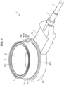
- FIG. 1 is a perspective view of a magnetostrictive torque sensor 1 according to an embodiment of the present invention.
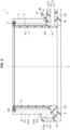
- FIG. 2 is a cross-sectional view around a detection coil 2 of the magnetostrictive torque sensor 1 in the embodiment of the present invention.
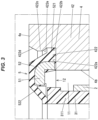
- FIG. 3 is an enlarged view around a plug member 5 in FIG. 2 .
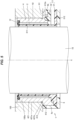
- FIG. 4 is a cross-sectional view around a heat shrinkable tube 8 of the magnetostrictive torque sensor 1 in the embodiment of the present invention.
- FIG. 5 is a schematic diagram showing the state of using the magnetostrictive torque sensor 1 in the embodiment of the invention.
- the magnetostrictive torque sensor 1 is used to measure the rotational torque applied to a magnetostrictive member 10 (see FIG. 5 ) having magnetostrictive properties. Magnetostriction is a phenomenon in which distortion (strain) appears in a ferromagnetic material when a magnetic field is applied to the ferromagnetic material to magnetize it. The magnetostrictive torque sensor 1 reversely utilizes this phenomenon and detects the torque acting on the magnetostrictive member 10 by detecting the magnetic field generated by the distortion of the magnetostrictive member 10 with the detection coil 2.
- the magnetostrictive member 10 whose rotational torque is to be measured can be, e.g., a predetermined rotating shaft used in a vehicle.
- the magnetostrictive torque sensor 1 comprises a detection coil 2, a housing 3, a magnetic ring 4, a plug member 5, a resin mold section 6, a cable 7, and a heat shrinkable tube 8.
- the detection coil 2 is arranged so as to surround the magnetostrictive member 10 from the outer peripheral side.
- the detection coil 2 outputs an electric signal corresponding to the magnitude of torque applied to the magnetostrictive member 10 to a control device or the like outside the magnetostrictive torque sensor 1 through the cable 7.
- the detection coil 2 can be configured by, for example, a pattern formed on a flexible substrate, or can be configured by winding an insulated wire (i.e., electrically insulated electric wire) in a coil shape.
- the configuration of the detection coil 2, such as the shape and number, can adopt the configuration of detection coils of conventional magnetostrictive torque sensors.
- the detection coil 2 is fixed to housing 3.
- the housing 3 is made of an electrically insulating resin or the like.
- the housing 3 is a combination of a first housing 31 and a second housing 32.
- the first housing 31 has a substantially cylindrical facing portion 311 facing the magnetic ring 4 across the detection coil 2, and an extending portion 312 extending from one end portion of the facing portion 311 to the outer peripheral side of the facing portion 311.
- the facing portion 311 is formed substantially coaxially with the magnetostrictive member 10, the detection coil 2, and the magnetic ring 4.
- a direction in which a central axis C of the magnetostrictive member 10, the facing portion 311, the detection coil 2, and the magnetic ring 4 extends is referred to as an axial direction.
- one side in the axial direction the side where the facing portion 311 stands against the extending portion 312 (for example, the upper side in FIG. 2 ) is referred to as an upper side, and the opposite side (for example, the lower side in FIG. 2 ) is referred to as a lower side.
- a vertical direction is for convenience, and does not limit the posture of the magnetostrictive torque sensor 1 with respect to the vertical direction when the magnetostrictive torque sensor 1 is used.
- the detection coil 2 is fixed to an outer peripheral surface of the facing portion 311.
- the flexible substrate may be adhered to the outer peripheral surface of the facing portion 311 using an adhesive or the like.
- the extending portion 312 is formed to extend in one direction perpendicular to the axial direction from the lower end portion of the facing portion 311.
- a wiring (not shown) between the detection coil 2 and the cable 7 is arranged on the upper side of the extending portion 312. This wiring (not shown) is accommodated in a wiring space 30 surrounded by the first housing 31 and the second housing 32.
- the second housing 32 is arranged above the extending portion 312 and surrounds the wiring space 30 together with the first housing 31.
- the second housing 32 is formed to extend in one direction perpendicular to the axial direction, like the extending portion 312.
- An end portion of the second housing 32 closer to the facing portion 311 is provided with a retaining protrusion (i.e., retaining projection) 321 protruding upward.
- the retaining protrusion 321 is arranged to fill a retaining recess 411a provided on a lower surface of the magnetic ring 4.
- a resin for forming the second housing 32 enters the retaining recess 411a, so that the retaining protrusion 321 has the same shape as the space in the retaining recess 411a.
- an inner peripheral surface of the retaining recess 411a is formed in a screw groove shape, and accordingly, the outer peripheral surface of the retaining protrusion 321 is formed in a screw thread shape.
- the inner peripheral surface of the retaining recess 411a and the outer peripheral surface of the retaining protrusion 321 may adopt other concave and convex shapes as long as they are secured against each other.
- the magnetic ring 4 is formed to face the facing portion 311 across the detection coil 2.
- the magnetic ring 4 forms an arrangement space 11 in which the detection coil 2 is arranged between the facing portion 311 and the magnetic ring 4.
- the magnetic ring 4 is formed by forming a substantially cylindrical ferromagnetic material (soft magnetic material) made of metal (including an alloy) such as iron.
- the magnetic ring 4 has the function of preventing the magnetic flux generated by the detection coil 2 from leaking to the outside and reducing the torque measurement accuracy of the magnetostrictive torque sensor 1.
- the arrangement space 11 is closed (plugged) at its lower side by the first housing 31, partially connected to the wiring space 30, and closed at its upper side by the plug member 5.
- the magnetic ring 4 has a large-diameter portion 41 at the lower end portion, and a small-diameter portion 42 having a smaller outer diameter than the large-diameter portion 41 above the large-diameter portion 41.
- a fitting recess 411 that is recessed upward and is fitted to the second housing 32 is formed on a lower surface of the large-diameter portion 41.
- the retaining recess 411a is formed so as to open to a bottom surface of the fitting recess 411.
- a portion of the lower surface of the large-diameter portion 41 other than the portion where the fitting recess 411 is formed faces the upper surface of the first housing 31.
- An outer peripheral surface of the large-diameter portion 41 is a covered outer peripheral surface 412, which is covered with the resin mold section 6, and an outer peripheral surface of the small-diameter portion 42 is an exposed outer peripheral surface 421, which is exposed from the resin mold section 6.
- the covered outer peripheral surface 412 has an enlarged diameter surface portion 412a that expands downward.
- the enlarged diameter surface portion 412a is tapered.
- the shape of the enlarged diameter surface portion 412a is not limited to a tapered shape as long as it can prevent the magnetic ring 4 from slipping off the resin mold section 6 upward.
- the enlarged diameter surface portion 412a may be formed to have a step portion in which an outer diameter gradually increases as progresses downward.
- An upward-facing annular surface 413 is provided between the covered outer peripheral surface 412 and the exposed outer peripheral surface 421 on the surface of the magnetic ring 4.
- the annular surface 413 has an annular shape and is formed in a plane perpendicular to the axial direction.
- the exposed outer peripheral surface 421 has a cylindrical surface 421a, and a concave surface 421b that is formed below the cylindrical surface 421a and recessed radially inwardly from the cylindrical surface 421a.
- the cylindrical surface 421a is formed from the upper end of the exposed outer peripheral surface 421 to the concave surface 421b, and is formed in a cylindrical shape parallel to the axial direction.
- the concave surface 421b is formed along the entire circumference of a lower end portion of the exposed outer peripheral surface 421.
- the magnetostrictive torque sensor 1 is fixed to an attachment target 100 made of metal, to which the magnetostrictive torque sensor 1 is attached, by fitting the magnetic ring 4 to an inner peripheral surface of an attachment hole 100a of the attachment target 100 in such a manner that the exposed outer peripheral surface 421 faces the inner peripheral surface of the attachment hole 100a.
- the magnetic ring 4 is fitted onto the inner peripheral surface of the attachment hole 100a so as to have a loose fit or a tight fit.
- the cylindrical surface 421a and the attachment hole 100a must be formed with high precision.
- both the magnetic ring 4 constituting the cylindrical surface 421a and the attachment target 100 constituting the attachment hole 100a are made of metal, so the cylindrical surface 421a and the attachment hole 100a can be formed with high precision.
- the magnetostrictive torque sensor 1 is inserted into the attachment hole 100a until the annular surface 413 abuts the attachment target 100.
- the concave surface 421b is formed at the lower end portion of the exposed outer peripheral surface 421, the magnetostrictive torque sensor 1 can be inserted into the attachment hole 100a until the annular surface 413 abuts the attachment target 100.
- an annular portion formed around the magnetic ring 4 is referred to as a first portion 6a, and a portion extending from the first portion 6a and covering the extending portion 312 of the first housing 31 and the second housing 32 is referred to as a second portion 6b.
- the attachment target 100 can be formed with a recess for fitting the second portion 6b.
- the magnetostrictive torque sensor 1 is restricted from rotating with respect to the attachment target 100 by the second portion 6b interfering with the recess of the attachment target 100.
- the magnetostrictive torque sensor 1 in order to prevent the magnetostrictive torque sensor 1 from slipping out of the attachment hole 100a, it is possible to adopt a configuration in which a part of the attachment target 100 is brought into contact with the annular surface 413, and the lower side of the magnetostrictive torque sensor 1 is held by a retaining ring fitted in a circumferential groove provided in the attachment hole 100a.
- a part of the attachment target 100 is brought into contact with the annular surface 413, and a protrusion protruding outward which is provided on the first portion 6a of the resin mold section 6 is fitted into a circumferential groove provided in the attachment hole 100a, to prevent the magnetostrictive torque sensor 1 from slipping out of the inner peripheral surface of the attachment hole 100a.
- a flange projecting outward is provided on the first portion 6a of the resin mold section 6, and a bolt is inserted through a collar provided on the flange and screwed into a female threaded hole provided on the attachment target 100, so that the magnetostrictive torque sensor 1 may be bolted to the attachment target 100.
- the magnetic ring 4 when the magnetic ring 4 is attached to the inner peripheral surface of the attachment hole 100a in a tight fit, the magnetic ring 4 can be attached to the inner peripheral surface of the attachment hole 100a by, for example, press fitting. In addition, as long as the magnetic ring 4 is configured to fit into the attachment hole 100a, it is possible to adopt various aspects.
- a step portion 422 is formed between an upper end surface 4a and an inner peripheral surface 4b of the magnetic ring 4.
- a plug member 5 is fitted to the step portion 422.
- the step portion 422 has a first surface 422a facing upward and connected to the inner peripheral surface 4b of the magnetic ring 4, and a second surface 422b facing radially inwardly and connected to the upper end surface 4a of the magnetic ring 4.
- the plug member 5 is arranged to contact both the first surface 422a and the lower end portion of the second surface 422b.
- the plug member 5 has an outer diameter greater than an inner diameter of the lower end portion of the second surface 422b in a free state before being assembled to the step portion 422, and is press-fitted into the step portion 422.
- the magnetic ring 4 is made of metal, and the surface including the second surface 422b can be formed with high precision. It becomes easier to ensure the sealing property between the plug member 5 and the second surface 422b with the second surface 422b being formed with high precision.
- an inward protrusion (i.e., inner periphery protrusion) 422c that protrudes radially inwardly is formed above the plug member 5 on the second surface 422b.
- the inward protrusion 422c has the function of preventing the plug member 5 from slipping out of the step portion 422 upward.
- the inner peripheral surface of the inward protrusion 422c has, at its upper end portion, an upper end tapered surface 422d with a tapered configuration in which a diameter decreases downward, and at its lower end portion, a lower end tapered surface 422e with a tapered configuration in which a diameter expands downward. Accordingly, when inserting the plug member 5 into the step portion 422, the plug member 5 is smoothly guided to a predetermined position within the step portion 422.
- the plug member 5 closes an opening 12, which is formed between the upper end portion of the magnetic ring 4 and the upper end portion of the facing portion 311 and opens upward.
- the plug member 5 is formed over the entire circumferences of the magnetic ring 4 and the facing portion 311.
- the plug member 5 has a core portion 51 made of a cold-rolled steel plate such as SPCC (Steel Plate Cold Commercial) and maintaining the shape of the plug member 5, and an elastic portion 52 made of elastically deformable rubber covering the core portion 51.
- the core portion 51 is formed to have an L-shaped cross-section.
- the core portion 51 is embedded in the elastic portion 52 so as not to be exposed upward from the elastic portion 52.
- the elastic portion 52 has a portion 521 configured to be accommodated in the step portion 422 on its outer peripheral portion, and an elastic contact piece 522 that elastically contacts the upper end surface of the facing portion 311 in the axial direction.
- the elastic contact piece 522 is bent upward, so that a downward restoring force is always generated in the elastic contact piece 522. Due to this restoring force, the elastic contact piece 522 abuts on the upper surface of the facing portion 311 and the sealing property between the elastic contact piece 522 and the upper surface of the facing portion 311 is ensured.
- the resin mold section 6 is molded to cover the housing 3 while exposing the magnetic ring 4 and the plug member 5.
- the resin mold section 6 generally covers a surface of a portion of the magnetostrictive torque sensor 1 below the annular surface 413 of the magnetic ring 4.
- the resin mold section 6 does not cover a portion of the magnetostrictive torque sensor 1 above the annular surface 413, the inner peripheral surface of the facing portion 311 of the first housing 31, and a portion 313 around the facing portion 311 on the lower surface of the first housing 31.
- the portion 313 is a portion where the die abuts with the housing 3 when molding the resin mold section 6.
- a part of the resin mold section 6 is also provided on the covered outer peripheral surface 412 of the magnetic ring 4.
- the resin mold section 6 is provided with an outer annular surface 61 formed substantially flush or coplanar with the annular surface 413 of the magnetic ring 4. As shown in FIGS. 1 and 4 , the cable 7 is drawn out from the housing 3 and the resin mold section 6.
- the cable 7 includes one or more wires (i.e., electric wires) 71 electrically connected to the detection coil 2, and a sheath 72 surrounding the one or more wires 71. As shown in FIG. 4 , there are plural wires 71 in the present embodiment, and the sheath 72 collectively covers the plural wires 71. Each wire 71 is a covered wire (i.e., coated wire) with a core wire and a coating.
- the sheath 72 is formed by forming a resin or the like having electrically insulating property into a cylindrical shape.
- the plural wires 71 exposed from the sheath 72 are arranged in the wiring space 30 in the housing 3 (i.e., the first housing 31 and the second housing 32), and the sheath 72 is drawn out from an end portion 33 on the far side from the facing portion 311 in the housing 3.
- the end portion 33 of the housing 3 is annularly formed by the first housing 31 and the second housing 32 and exposed from the resin mold section 6.
- the heat shrinkable tube 8 is provided to prevent liquid or the like from entering the housing 3 through a gap between the housing 3 and the resin mold section 6 and the cable 7.
- the heat shrinkable tube 8 is formed so as to collectively cover the boundary between the cable 7 and the housing 3 and the resin mold section 6 when viewed from the outside.
- the heat shrinkable tube 8 is configured to shrink at least toward the inner peripheral side (i.e., radially inwardly) of the heat shrinkable tube 8 when the temperature reaches a predetermined temperature or higher.
- the heat shrinkable tube 8 covers the end portion of the resin mold section 6 on the far side from the facing portion 311, the end portion 33 of the housing 3, and the end portion of the sheath 72 of the cable 7 on the housing 3-side.
- the heat shrinkable tube 8 is configured in such a manner that the length in a cable longitudinal direction of a portion covering the sheath 72 is longer than the length in the cable longitudinal direction of a portion covering the end portion 33 of the housing 3 and the resin mold section 6.
- a so-called hot melt which is an adhesive material that melts at a predetermined temperature or higher and hardens again at a temperature lower than a predetermined temperature, may be provided on the inner peripheral portion of the heat shrinkable tube 8.
- the heat shrinkable tube 8 is provided by, for example, the following method. First, the heat shrinkable tube 8 before heat shrinking, which has an outer diameter larger than the parts to be covered by the heat shrinkable tube 8 in the housing 3, the resin mold section 6, and the cable 7, is arranged so as to surround the parts to be covered by the heat shrinkable tube 8 in the housing 3, the resin mold section 6, and the cable 7. Next, by heating and shrinking the heat shrinkable tube 8, the heat shrinkable tube 8 is brought into close contact with the surfaces of the housing 3, the resin mold section 6, and the cable 7, either directly or via the hot melt, if any.
- the heat shrinkable tube 8 is provided as described above.
- the resin mold section 6 covers the housing 3 while exposing the magnetic ring 4 and the plug member 5. Therefore, since the resin mold section 6 is not arranged around the opening 12, the resin mold section 6 is prevented from entering the periphery of the detection coil 2 through the opening 12 when the resin mold section 6 is molded. Moreover, the magnetostrictive torque sensor 1 of the present embodiment includes the plug member 5 that closes the opening 12. As a result, even if the magnetic ring 4 is exposed from the resin mold section 6, it is possible to prevent foreign matters from entering the periphery of the detection coil 2 through the opening 12.
- the step portion 422 is formed between the upper end surface 4a and the inner peripheral surface 4b of the magnetic ring 4, and the plug member 5 is fitted in the step portion 422. This facilitates positioning (e.g., alignment) of the plug member 5 with respect to the magnetic ring 4.
- the shape of the step portion 422 is desired to be formed with high precision because it affects the sealing property between the plug member 5 and the step portion 422. Therefore, by forming the step portion 422 on the magnetic ring 4 made of a ferromagnetic material (i.e., metal), the step portion 422 can be formed with higher precision than when the step portion 422 is formed on a resin member or the like. Thus, it is easy to secure the sealing property with the plug member 5. For example, in the case of a resin member, the surface shape tends to be different from the desired shape due to molding shrinkage of the resin member. However, the surface of the magnetic ring 4 made of the ferromagnetic material is formed with relatively high precision.
- the inner peripheral surface of the step portion 422 has the inward protrusion 422c protruding toward the inner peripheral side (i.e., radially inwardly) at a position above the plug member 5. Therefore, it is possible to prevent the magnetic ring 4 from slipping out from the step portion 422.
- the outer peripheral surface of the magnetic ring 4 has the covered outer peripheral surface 412 covered by the resin mold section 6, and the exposed outer peripheral surface 421 located above the covered outer peripheral surface 412 and exposed from the resin mold section 6.
- the surface of the magnetic ring 4 made of ferromagnetic material (i.e., metal) is formed with higher precision than the surface of the resin member. Therefore, by forming the outer surface of the magnetostrictive torque sensor 1 with the exposed outer peripheral surface 421, it is possible to prevent the outer shape of the magnetostrictive torque sensor 1 from deviating from a desired shape.
- the magnetostrictive torque sensor 1 may easily interfere with the attachment object and parts arranged around it. However, this can be suppressed in the present embodiment.
- the lower surface of the magnetic ring 4 faces the housing 3, and the covered outer peripheral surface 412 has the enlarged diameter surface portion 412a whose diameter increases downward. Therefore, the housing 3 prevents the magnetic ring 4 from slipping out of the resin mold section 6 downward, and the resin mold section 6 provided on the enlarged diameter surface portion 412a prevents the magnetic ring 4 from slipping out of the resin mold section 6 upward.
- the magnetostrictive torque sensor 1 is configured to be attached to the attachment target 100 by fitting the magnetic ring 4 to the inner peripheral surface of the attachment hole 100a in such a manner that the exposed outer peripheral surface 421 faces the inner peripheral surface of the attachment hole 100a. This makes it possible to easily attach the magnetostrictive torque sensor 1 to the attachment target 100.
- the magnetostrictive torque sensor 1 can be attached to the attachment target 100 without using bolts.
- the magnetic ring 4 that can be formed with high precision is fitted to the inner peripheral surface of the attachment hole 100a at the exposed outer peripheral surface 421, the magnetic ring 4 can be easily fitted to the inner peripheral surface of the attachment hole 100a.
- the resin member when a resin member, which is difficult to form with high precision, is fitted to the inner peripheral surface of the attachment hole 100a, the resin member may be formed too large to fit into the attachment hole 100a. The occurrence of such a situation can be suppressed in the present embodiment.
- the outer diameter of the covered outer peripheral surface 412 is larger than the outer diameter of the exposed outer peripheral surface 421, and the upward-facing annular surface 413 is formed between the covered outer peripheral surface 412 and the exposed outer peripheral surface 421 on the surface of the magnetic ring 4. Therefore, the magnetostrictive torque sensor 1 can be easily positioned (e.g., aligned) with respect to the attachment target 100 by making the attachment target 100 abut the annular surface 413 when the magnetic ring 4 is fitted to the inner peripheral surface of the attachment hole 100a
- the concave surface 421b recessed toward the inner peripheral side is formed at the end portion of the exposed outer peripheral surface 421 on the covered outer peripheral surface 412-side. Therefore, it is possible to fit the magnetic ring 4 to the inner peripheral surface of the attachment hole 100a until the annular surface 413 abuts the attachment target 100.
- the concave surface 421b is not formed on the exposed outer peripheral surface 421, it is difficult to form a corner between the exposed outer peripheral surface 421 and the annular surface 413 at 90 degrees in terms of manufacturing.
- a slight curved surface i.e., round surface is formed between the exposed outer peripheral surface 421 and the annular surface 413.
- the concave surface 421b is not formed on the exposed outer peripheral surface 421, when the magnetic ring 4 is fitted to the inner peripheral surface of the attachment hole 100a, the curved surface interferes with the attachment target 100, so that the exposed outer peripheral surface 421 cannot fit into the inner peripheral surface of the attachment hole 100a until the annular surface 413 abuts the attachment target 100. Therefore, in the present embodiment, by providing the concave surface 421b at the lower end portion of the exposed outer peripheral surface 421, the annular surface 413 and the attachment target 100 can abut with each other when the magnetic ring 4 is fitted into the inner peripheral surface of the attachment hole 100a.
- a magnetostrictive torque sensor 1 for detecting a torque applied to a magnetostrictive member 10 having magnetostrictive properties, includes a detection coil 2 arranged on an outer peripheral side of the magnetostrictive member 10; a magnetic ring 4 composed of a ferromagnetic material arranged on an outer peripheral side of the detection coil 2; a housing 3 having a facing portion 311 facing the magnetic ring 4 across the detection coil 2; a plug member 5 closing an opening 12 formed between the magnetic ring 4 and the facing portion 311; a resin mold section 6 covering the housing 3 while exposing the magnetic ring 4 and the plug member 5; a cable 7 electrically connected to the detection coil 2 and drawn out from the housing 3 and the resin mold section 6; and a heat shrinkable tube 8 covering the housing 3, a portion of the resin mold section 6, and an end portion of the cable 7 exposed from the housing 3 and the resin mold section 6.
- a step portion 422 is formed between an end surface 4a on an opening side of the opening 12 and an inner peripheral surface 4b in the magnetic ring 4, and the plug member 5 is fitted into the step portion 422.
- an inner peripheral surface of the step portion 422 has an inward protrusion 422c that protrudes radially inwardly at a position closer to the opening side than the plug member 5.
- an outer peripheral surface of the magnetic ring 4 has a covered outer peripheral surface 412 covered with the resin mold section 6, and an exposed outer peripheral surface 421 positioned closer to the opening side than the covered outer peripheral surface 412 and exposed from the resin mold section 6.
- a surface of the magnetic ring 4 opposite to the opening side faces the housing 3, and the covered outer peripheral surface 412 includes an enlarged diameter surface portion 412a that expands toward a side opposite to the opening side.
- the magnetostrictive torque sensor 1 as described in the feature [4] or [5] is configured to be attached to an attachment target 100 by fitting the magnetic ring 4 in such a manner that the exposed outer peripheral surface 421 faces an inner peripheral surface of an attachment hole 100a of the attachment target 100.
- an outer diameter of the covered outer peripheral surface 412 is larger than an outer diameter of the exposed outer peripheral surface 421, and an annular surface 413 facing the opening side is formed between the covered outer peripheral surface 412 and the exposed outer peripheral surface 421 on a surface of the magnetic ring 4.
- an end portion of the exposed outer peripheral surface 421 on a side of the covered outer peripheral surface 412 is formed with a concave surface 421b recessed radially inwardly.
Landscapes
- Physics & Mathematics (AREA)
- Electromagnetism (AREA)
- General Physics & Mathematics (AREA)
- Power Steering Mechanism (AREA)
Abstract
Description
- The present patent application claims the priority of
Japanese patent application No. 2021-174670 filed on October 26, 2021 - The present invention relates to a magnetostrictive torque sensor.
-
Patent Literature 1 discloses a magnetostrictive torque sensor in which a sensor section is covered with an inner mold. The sensor section has a detection coil, a resin bobbin arranged on an inner peripheral side of the detection coil, and a magnetic body ring made of a ferromagnetic material arranged on an outer peripheral side of the detection coil. - Patent Literature 1:
JP-A-2020-085814 - In the magnetostrictive torque sensor disclosed in
Patent Literature 1, there is a possibility that a resin for forming the inner mold may enter an arrangement space for the detection coil from between the bobbin and the magnetic body ring during molding of the inner mold. If the inner mold enters the arrangement space for the detection coil, the position of the detection coil may shift from a desired position, or the detection coil may break. - Therefore, it is an object of the present invention to provide a magnetostrictive torque sensor capable of suppressing an entry of a resin mold section around a detection coil.
- So as to achieve the above object, one aspect of the present invention provides: a magnetostrictive torque sensor for detecting a torque applied to a magnetostrictive member having magnetostrictive properties, comprising:
- a detection coil arranged on an outer peripheral side of the magnetostrictive member;
- a magnetic ring comprising a ferromagnetic material arranged on an outer peripheral side of the detection coil;
- a housing having a facing portion facing the magnetic ring across the detection coil;
- a plug member closing an opening formed between the magnetic ring and the facing portion;
- a resin mold section covering the housing while exposing the magnetic ring and the plug member;
- a cable electrically connected to the detection coil and drawn out from the housing and the resin mold section; and
- a heat shrinkable tube covering the housing, a portion of the resin mold section, and an end portion of the cable exposed from the housing and the resin mold section.
- According to the present invention, it is possible to provide a magnetostrictive torque sensor capable of suppressing an entry of a resin mold section around the detection coil.
-
-
FIG. 1 is a perspective view of a magnetostrictive torque sensor according to an embodiment of the present invention. -
FIG. 2 is a cross-sectional view around a detection coil of the magnetostrictive torque sensor in the embodiment of the present invention. -
FIG. 3 is an enlarged view around a plug member inFIG. 2 . -
FIG. 4 is a cross-sectional view around a heat shrinkable tube of the magnetostrictive torque sensor in the embodiment of the present invention. -
FIG. 5 is a schematic diagram showing the state of using the magnetostrictive torque sensor in the embodiment of the invention. - An embodiment of the present invention will be described with reference to
FIGS. 1 to 5 . It should be noted that the embodiment described below is shown as a preferred specific example for carrying out the present invention, and there are portions that specifically illustrate various technically preferable technical matters. However, the technical scope of the present invention is not limited to this specific embodiment. -
FIG. 1 is a perspective view of amagnetostrictive torque sensor 1 according to an embodiment of the present invention.FIG. 2 is a cross-sectional view around adetection coil 2 of themagnetostrictive torque sensor 1 in the embodiment of the present invention. -
FIG. 3 is an enlarged view around aplug member 5 inFIG. 2 .FIG. 4 is a cross-sectional view around aheat shrinkable tube 8 of themagnetostrictive torque sensor 1 in the embodiment of the present invention.FIG. 5 is a schematic diagram showing the state of using themagnetostrictive torque sensor 1 in the embodiment of the invention. - The
magnetostrictive torque sensor 1 is used to measure the rotational torque applied to a magnetostrictive member 10 (seeFIG. 5 ) having magnetostrictive properties. Magnetostriction is a phenomenon in which distortion (strain) appears in a ferromagnetic material when a magnetic field is applied to the ferromagnetic material to magnetize it. Themagnetostrictive torque sensor 1 reversely utilizes this phenomenon and detects the torque acting on themagnetostrictive member 10 by detecting the magnetic field generated by the distortion of themagnetostrictive member 10 with thedetection coil 2. Themagnetostrictive member 10 whose rotational torque is to be measured (i.e., measuring object) can be, e.g., a predetermined rotating shaft used in a vehicle. Themagnetostrictive torque sensor 1 comprises adetection coil 2, ahousing 3, amagnetic ring 4, aplug member 5, aresin mold section 6, acable 7, and aheat shrinkable tube 8. - As shown in
FIG. 5 , thedetection coil 2 is arranged so as to surround themagnetostrictive member 10 from the outer peripheral side. Thedetection coil 2 outputs an electric signal corresponding to the magnitude of torque applied to themagnetostrictive member 10 to a control device or the like outside themagnetostrictive torque sensor 1 through thecable 7. Thedetection coil 2 can be configured by, for example, a pattern formed on a flexible substrate, or can be configured by winding an insulated wire (i.e., electrically insulated electric wire) in a coil shape. The configuration of thedetection coil 2, such as the shape and number, can adopt the configuration of detection coils of conventional magnetostrictive torque sensors. Thedetection coil 2 is fixed tohousing 3. - As shown in
FIG. 2 , thehousing 3 is made of an electrically insulating resin or the like. In this embodiment, thehousing 3 is a combination of afirst housing 31 and asecond housing 32. Thefirst housing 31 has a substantially cylindrical facingportion 311 facing themagnetic ring 4 across thedetection coil 2, and an extendingportion 312 extending from one end portion of the facingportion 311 to the outer peripheral side of the facingportion 311. The facingportion 311 is formed substantially coaxially with themagnetostrictive member 10, thedetection coil 2, and themagnetic ring 4. Hereinafter, a direction in which a central axis C of themagnetostrictive member 10, the facingportion 311, thedetection coil 2, and themagnetic ring 4 extends is referred to as an axial direction. Also, one side in the axial direction, the side where the facingportion 311 stands against the extending portion 312 (for example, the upper side inFIG. 2 ) is referred to as an upper side, and the opposite side (for example, the lower side inFIG. 2 ) is referred to as a lower side. Note that a vertical direction is for convenience, and does not limit the posture of themagnetostrictive torque sensor 1 with respect to the vertical direction when themagnetostrictive torque sensor 1 is used. - The
detection coil 2 is fixed to an outer peripheral surface of the facingportion 311. For example, when thedetection coil 2 is composed of a pattern on a surface of a flexible substrate, the flexible substrate may be adhered to the outer peripheral surface of the facingportion 311 using an adhesive or the like. - The extending
portion 312 is formed to extend in one direction perpendicular to the axial direction from the lower end portion of the facingportion 311. A wiring (not shown) between thedetection coil 2 and thecable 7 is arranged on the upper side of the extendingportion 312. This wiring (not shown) is accommodated in awiring space 30 surrounded by thefirst housing 31 and thesecond housing 32. - The
second housing 32 is arranged above the extendingportion 312 and surrounds thewiring space 30 together with thefirst housing 31. Thesecond housing 32 is formed to extend in one direction perpendicular to the axial direction, like the extendingportion 312. An end portion of thesecond housing 32 closer to the facingportion 311 is provided with a retaining protrusion (i.e., retaining projection) 321 protruding upward. Theretaining protrusion 321 is arranged to fill aretaining recess 411a provided on a lower surface of themagnetic ring 4. When thesecond housing 32 is molded, a resin for forming thesecond housing 32 enters theretaining recess 411a, so that theretaining protrusion 321 has the same shape as the space in theretaining recess 411a. In this embodiment, an inner peripheral surface of the retainingrecess 411a is formed in a screw groove shape, and accordingly, the outer peripheral surface of the retainingprotrusion 321 is formed in a screw thread shape. Note that the inner peripheral surface of the retainingrecess 411a and the outer peripheral surface of the retainingprotrusion 321 may adopt other concave and convex shapes as long as they are secured against each other. - The
magnetic ring 4 is formed to face the facingportion 311 across thedetection coil 2. Themagnetic ring 4 forms anarrangement space 11 in which thedetection coil 2 is arranged between the facingportion 311 and themagnetic ring 4. Themagnetic ring 4 is formed by forming a substantially cylindrical ferromagnetic material (soft magnetic material) made of metal (including an alloy) such as iron. By covering thedetection coil 2 from the outer peripheral side, themagnetic ring 4 has the function of preventing the magnetic flux generated by thedetection coil 2 from leaking to the outside and reducing the torque measurement accuracy of themagnetostrictive torque sensor 1. Thearrangement space 11 is closed (plugged) at its lower side by thefirst housing 31, partially connected to thewiring space 30, and closed at its upper side by theplug member 5. - The
magnetic ring 4 has a large-diameter portion 41 at the lower end portion, and a small-diameter portion 42 having a smaller outer diameter than the large-diameter portion 41 above the large-diameter portion 41. A fitting recess 411 that is recessed upward and is fitted to thesecond housing 32 is formed on a lower surface of the large-diameter portion 41. The retainingrecess 411a is formed so as to open to a bottom surface of the fitting recess 411. A portion of the lower surface of the large-diameter portion 41 other than the portion where the fitting recess 411 is formed faces the upper surface of thefirst housing 31. - An outer peripheral surface of the large-
diameter portion 41 is a covered outerperipheral surface 412, which is covered with theresin mold section 6, and an outer peripheral surface of the small-diameter portion 42 is an exposed outerperipheral surface 421, which is exposed from theresin mold section 6. The covered outerperipheral surface 412 has an enlargeddiameter surface portion 412a that expands downward. By forming the enlargeddiameter surface portion 412a on the covered outerperipheral surface 412, themagnetic ring 4 is prevented from slipping upward from theresin mold section 6. In this embodiment, the enlargeddiameter surface portion 412a is tapered. The shape of the enlargeddiameter surface portion 412a is not limited to a tapered shape as long as it can prevent themagnetic ring 4 from slipping off theresin mold section 6 upward. For example, the enlargeddiameter surface portion 412a may be formed to have a step portion in which an outer diameter gradually increases as progresses downward. - An upward-facing
annular surface 413 is provided between the covered outerperipheral surface 412 and the exposed outerperipheral surface 421 on the surface of themagnetic ring 4. Theannular surface 413 has an annular shape and is formed in a plane perpendicular to the axial direction. - The exposed outer
peripheral surface 421 has acylindrical surface 421a, and aconcave surface 421b that is formed below thecylindrical surface 421a and recessed radially inwardly from thecylindrical surface 421a. Thecylindrical surface 421a is formed from the upper end of the exposed outerperipheral surface 421 to theconcave surface 421b, and is formed in a cylindrical shape parallel to the axial direction. Theconcave surface 421b is formed along the entire circumference of a lower end portion of the exposed outerperipheral surface 421. - As shown in
FIG. 5 , themagnetostrictive torque sensor 1 is fixed to anattachment target 100 made of metal, to which themagnetostrictive torque sensor 1 is attached, by fitting themagnetic ring 4 to an inner peripheral surface of anattachment hole 100a of theattachment target 100 in such a manner that the exposed outerperipheral surface 421 faces the inner peripheral surface of theattachment hole 100a. Themagnetic ring 4 is fitted onto the inner peripheral surface of theattachment hole 100a so as to have a loose fit or a tight fit. Here, in order to fit themagnetic ring 4 onto the inner peripheral surface of theattachment hole 100a as intended, thecylindrical surface 421a and theattachment hole 100a must be formed with high precision. In the present embodiment, both themagnetic ring 4 constituting thecylindrical surface 421a and theattachment target 100 constituting theattachment hole 100a are made of metal, so thecylindrical surface 421a and theattachment hole 100a can be formed with high precision. Themagnetostrictive torque sensor 1 is inserted into theattachment hole 100a until theannular surface 413 abuts theattachment target 100. At this time, since theconcave surface 421b is formed at the lower end portion of the exposed outerperipheral surface 421, themagnetostrictive torque sensor 1 can be inserted into theattachment hole 100a until theannular surface 413 abuts theattachment target 100. - Here, measures for preventing the
magnetostrictive torque sensor 1 from rotating about the central axis C with respect to theattachment target 100 and from slipping out of theattachment hole 100a in the axial direction, in a state where themagnetostrictive torque sensor 1 is attached to theattachment target 100, will be explained. In theresin mold section 6, an annular portion formed around themagnetic ring 4 is referred to as afirst portion 6a, and a portion extending from thefirst portion 6a and covering the extendingportion 312 of thefirst housing 31 and thesecond housing 32 is referred to as asecond portion 6b. Although not shown, in order to prevent themagnetostrictive torque sensor 1 from rotating with respect to theattachment target 100, theattachment target 100 can be formed with a recess for fitting thesecond portion 6b. In this case, themagnetostrictive torque sensor 1 is restricted from rotating with respect to theattachment target 100 by thesecond portion 6b interfering with the recess of theattachment target 100. Although not shown, in order to prevent themagnetostrictive torque sensor 1 from slipping out of theattachment hole 100a, it is possible to adopt a configuration in which a part of theattachment target 100 is brought into contact with theannular surface 413, and the lower side of themagnetostrictive torque sensor 1 is held by a retaining ring fitted in a circumferential groove provided in theattachment hole 100a. Alternatively, it is possible to adopt a configuration in which a part of theattachment target 100 is brought into contact with theannular surface 413, and a protrusion protruding outward which is provided on thefirst portion 6a of theresin mold section 6 is fitted into a circumferential groove provided in theattachment hole 100a, to prevent themagnetostrictive torque sensor 1 from slipping out of the inner peripheral surface of theattachment hole 100a. Furthermore, although not shown, a flange projecting outward is provided on thefirst portion 6a of theresin mold section 6, and a bolt is inserted through a collar provided on the flange and screwed into a female threaded hole provided on theattachment target 100, so that themagnetostrictive torque sensor 1 may be bolted to theattachment target 100. Furthermore, when themagnetic ring 4 is attached to the inner peripheral surface of theattachment hole 100a in a tight fit, themagnetic ring 4 can be attached to the inner peripheral surface of theattachment hole 100a by, for example, press fitting. In addition, as long as themagnetic ring 4 is configured to fit into theattachment hole 100a, it is possible to adopt various aspects. - As shown in
FIG. 3 , astep portion 422 is formed between anupper end surface 4a and an innerperipheral surface 4b of themagnetic ring 4. Aplug member 5 is fitted to thestep portion 422. Thestep portion 422 has afirst surface 422a facing upward and connected to the innerperipheral surface 4b of themagnetic ring 4, and asecond surface 422b facing radially inwardly and connected to theupper end surface 4a of themagnetic ring 4. Theplug member 5 is arranged to contact both thefirst surface 422a and the lower end portion of thesecond surface 422b. Theplug member 5 has an outer diameter greater than an inner diameter of the lower end portion of thesecond surface 422b in a free state before being assembled to thestep portion 422, and is press-fitted into thestep portion 422. As a result, when theplug member 5 is assembled to thestep portion 422, an outer peripheral end portion of theplug member 5 is in elastic contact with thesecond surface 422b, ensuring sealing between theplug member 5 and thesecond surface 422b. As described above, themagnetic ring 4 is made of metal, and the surface including thesecond surface 422b can be formed with high precision. It becomes easier to ensure the sealing property between theplug member 5 and thesecond surface 422b with thesecond surface 422b being formed with high precision. - In addition, an inward protrusion (i.e., inner periphery protrusion) 422c that protrudes radially inwardly is formed above the
plug member 5 on thesecond surface 422b. Theinward protrusion 422c has the function of preventing theplug member 5 from slipping out of thestep portion 422 upward. The inner peripheral surface of theinward protrusion 422c has, at its upper end portion, an upper end taperedsurface 422d with a tapered configuration in which a diameter decreases downward, and at its lower end portion, a lower end taperedsurface 422e with a tapered configuration in which a diameter expands downward. Accordingly, when inserting theplug member 5 into thestep portion 422, theplug member 5 is smoothly guided to a predetermined position within thestep portion 422. - The
plug member 5 closes anopening 12, which is formed between the upper end portion of themagnetic ring 4 and the upper end portion of the facingportion 311 and opens upward. Theplug member 5 is formed over the entire circumferences of themagnetic ring 4 and the facingportion 311. Theplug member 5 has acore portion 51 made of a cold-rolled steel plate such as SPCC (Steel Plate Cold Commercial) and maintaining the shape of theplug member 5, and anelastic portion 52 made of elastically deformable rubber covering thecore portion 51. Thecore portion 51 is formed to have an L-shaped cross-section. Thecore portion 51 is embedded in theelastic portion 52 so as not to be exposed upward from theelastic portion 52. Theelastic portion 52 has aportion 521 configured to be accommodated in thestep portion 422 on its outer peripheral portion, and anelastic contact piece 522 that elastically contacts the upper end surface of the facingportion 311 in the axial direction. Theelastic contact piece 522 is bent upward, so that a downward restoring force is always generated in theelastic contact piece 522. Due to this restoring force, theelastic contact piece 522 abuts on the upper surface of the facingportion 311 and the sealing property between theelastic contact piece 522 and the upper surface of the facingportion 311 is ensured. - As shown in
FIGS. 1 and2 , theresin mold section 6 is molded to cover thehousing 3 while exposing themagnetic ring 4 and theplug member 5. Theresin mold section 6 generally covers a surface of a portion of themagnetostrictive torque sensor 1 below theannular surface 413 of themagnetic ring 4. On the other hand, theresin mold section 6 does not cover a portion of themagnetostrictive torque sensor 1 above theannular surface 413, the inner peripheral surface of the facingportion 311 of thefirst housing 31, and aportion 313 around the facingportion 311 on the lower surface of thefirst housing 31. Theportion 313 is a portion where the die abuts with thehousing 3 when molding theresin mold section 6. - A part of the
resin mold section 6 is also provided on the covered outerperipheral surface 412 of themagnetic ring 4. Theresin mold section 6 is provided with an outerannular surface 61 formed substantially flush or coplanar with theannular surface 413 of themagnetic ring 4. As shown inFIGS. 1 and4 , thecable 7 is drawn out from thehousing 3 and theresin mold section 6. - The
cable 7 includes one or more wires (i.e., electric wires) 71 electrically connected to thedetection coil 2, and asheath 72 surrounding the one ormore wires 71. As shown inFIG. 4 , there areplural wires 71 in the present embodiment, and thesheath 72 collectively covers theplural wires 71. Eachwire 71 is a covered wire (i.e., coated wire) with a core wire and a coating. Thesheath 72 is formed by forming a resin or the like having electrically insulating property into a cylindrical shape. - The
plural wires 71 exposed from thesheath 72 are arranged in thewiring space 30 in the housing 3 (i.e., thefirst housing 31 and the second housing 32), and thesheath 72 is drawn out from anend portion 33 on the far side from the facingportion 311 in thehousing 3. Theend portion 33 of thehousing 3 is annularly formed by thefirst housing 31 and thesecond housing 32 and exposed from theresin mold section 6. The heat shrinkabletube 8 is provided to prevent liquid or the like from entering thehousing 3 through a gap between thehousing 3 and theresin mold section 6 and thecable 7. - The heat shrinkable
tube 8 is formed so as to collectively cover the boundary between thecable 7 and thehousing 3 and theresin mold section 6 when viewed from the outside. The heat shrinkabletube 8 is configured to shrink at least toward the inner peripheral side (i.e., radially inwardly) of the heatshrinkable tube 8 when the temperature reaches a predetermined temperature or higher. The heat shrinkabletube 8 covers the end portion of theresin mold section 6 on the far side from the facingportion 311, theend portion 33 of thehousing 3, and the end portion of thesheath 72 of thecable 7 on the housing 3-side. In the present embodiment, the heatshrinkable tube 8 is configured in such a manner that the length in a cable longitudinal direction of a portion covering thesheath 72 is longer than the length in the cable longitudinal direction of a portion covering theend portion 33 of thehousing 3 and theresin mold section 6. In addition, a so-called hot melt, which is an adhesive material that melts at a predetermined temperature or higher and hardens again at a temperature lower than a predetermined temperature, may be provided on the inner peripheral portion of the heatshrinkable tube 8. - The heat shrinkable
tube 8 is provided by, for example, the following method. First, the heatshrinkable tube 8 before heat shrinking, which has an outer diameter larger than the parts to be covered by the heatshrinkable tube 8 in thehousing 3, theresin mold section 6, and thecable 7, is arranged so as to surround the parts to be covered by the heatshrinkable tube 8 in thehousing 3, theresin mold section 6, and thecable 7. Next, by heating and shrinking the heatshrinkable tube 8, the heatshrinkable tube 8 is brought into close contact with the surfaces of thehousing 3, theresin mold section 6, and thecable 7, either directly or via the hot melt, if any. The heat shrinkabletube 8 is provided as described above. - In the
magnetostrictive torque sensor 1 of the present embodiment, theresin mold section 6 covers thehousing 3 while exposing themagnetic ring 4 and theplug member 5. Therefore, since theresin mold section 6 is not arranged around theopening 12, theresin mold section 6 is prevented from entering the periphery of thedetection coil 2 through theopening 12 when theresin mold section 6 is molded. Moreover, themagnetostrictive torque sensor 1 of the present embodiment includes theplug member 5 that closes theopening 12. As a result, even if themagnetic ring 4 is exposed from theresin mold section 6, it is possible to prevent foreign matters from entering the periphery of thedetection coil 2 through theopening 12. Furthermore, a part of thehousing 3 and theresin mold section 6 and the end portion of the exposedcable 7 from thehousing 3 and theresin mold section 6 are covered with the heatshrinkable tube 8. As a result, the foreign matters such as oil, and liquid can be prevented from entering the interior of themagnetostrictive torque sensor 1 through the gap between thehousing 3 and theresin mold section 6 and thecable 7. - The
step portion 422 is formed between theupper end surface 4a and the innerperipheral surface 4b of themagnetic ring 4, and theplug member 5 is fitted in thestep portion 422. This facilitates positioning (e.g., alignment) of theplug member 5 with respect to themagnetic ring 4. Here, the shape of thestep portion 422 is desired to be formed with high precision because it affects the sealing property between theplug member 5 and thestep portion 422. Therefore, by forming thestep portion 422 on themagnetic ring 4 made of a ferromagnetic material (i.e., metal), thestep portion 422 can be formed with higher precision than when thestep portion 422 is formed on a resin member or the like. Thus, it is easy to secure the sealing property with theplug member 5. For example, in the case of a resin member, the surface shape tends to be different from the desired shape due to molding shrinkage of the resin member. However, the surface of themagnetic ring 4 made of the ferromagnetic material is formed with relatively high precision. - In addition, the inner peripheral surface of the
step portion 422 has theinward protrusion 422c protruding toward the inner peripheral side (i.e., radially inwardly) at a position above theplug member 5. Therefore, it is possible to prevent themagnetic ring 4 from slipping out from thestep portion 422. - The outer peripheral surface of the
magnetic ring 4 has the covered outerperipheral surface 412 covered by theresin mold section 6, and the exposed outerperipheral surface 421 located above the covered outerperipheral surface 412 and exposed from theresin mold section 6. The surface of themagnetic ring 4 made of ferromagnetic material (i.e., metal) is formed with higher precision than the surface of the resin member. Therefore, by forming the outer surface of themagnetostrictive torque sensor 1 with the exposed outerperipheral surface 421, it is possible to prevent the outer shape of themagnetostrictive torque sensor 1 from deviating from a desired shape. If the outer shape of themagnetostrictive torque sensor 1 deviates from the desired shape, for example, when themagnetostrictive torque sensor 1 is attached to the member to be attached (i.e., attachment object), themagnetostrictive torque sensor 1 may easily interfere with the attachment object and parts arranged around it. However, this can be suppressed in the present embodiment. - In addition, the lower surface of the
magnetic ring 4 faces thehousing 3, and the covered outerperipheral surface 412 has the enlargeddiameter surface portion 412a whose diameter increases downward. Therefore, thehousing 3 prevents themagnetic ring 4 from slipping out of theresin mold section 6 downward, and theresin mold section 6 provided on the enlargeddiameter surface portion 412a prevents themagnetic ring 4 from slipping out of theresin mold section 6 upward. - Also, the
magnetostrictive torque sensor 1 is configured to be attached to theattachment target 100 by fitting themagnetic ring 4 to the inner peripheral surface of theattachment hole 100a in such a manner that the exposed outerperipheral surface 421 faces the inner peripheral surface of theattachment hole 100a. This makes it possible to easily attach themagnetostrictive torque sensor 1 to theattachment target 100. As an example, themagnetostrictive torque sensor 1 can be attached to theattachment target 100 without using bolts. In addition, since themagnetic ring 4 that can be formed with high precision is fitted to the inner peripheral surface of theattachment hole 100a at the exposed outerperipheral surface 421, themagnetic ring 4 can be easily fitted to the inner peripheral surface of theattachment hole 100a. That is, for example, when a resin member, which is difficult to form with high precision, is fitted to the inner peripheral surface of theattachment hole 100a, the resin member may be formed too large to fit into theattachment hole 100a. The occurrence of such a situation can be suppressed in the present embodiment. - In addition, the outer diameter of the covered outer
peripheral surface 412 is larger than the outer diameter of the exposed outerperipheral surface 421, and the upward-facingannular surface 413 is formed between the covered outerperipheral surface 412 and the exposed outerperipheral surface 421 on the surface of themagnetic ring 4. Therefore, themagnetostrictive torque sensor 1 can be easily positioned (e.g., aligned) with respect to theattachment target 100 by making theattachment target 100 abut theannular surface 413 when themagnetic ring 4 is fitted to the inner peripheral surface of theattachment hole 100a - The
concave surface 421b recessed toward the inner peripheral side (i.e., radially inwardly) is formed at the end portion of the exposed outerperipheral surface 421 on the covered outer peripheral surface 412-side. Therefore, it is possible to fit themagnetic ring 4 to the inner peripheral surface of theattachment hole 100a until theannular surface 413 abuts theattachment target 100. Here, for example, if theconcave surface 421b is not formed on the exposed outerperipheral surface 421, it is difficult to form a corner between the exposed outerperipheral surface 421 and theannular surface 413 at 90 degrees in terms of manufacturing. A slight curved surface (i.e., round surface) is formed between the exposed outerperipheral surface 421 and theannular surface 413. Therefore, if theconcave surface 421b is not formed on the exposed outerperipheral surface 421, when themagnetic ring 4 is fitted to the inner peripheral surface of theattachment hole 100a, the curved surface interferes with theattachment target 100, so that the exposed outerperipheral surface 421 cannot fit into the inner peripheral surface of theattachment hole 100a until theannular surface 413 abuts theattachment target 100. Therefore, in the present embodiment, by providing theconcave surface 421b at the lower end portion of the exposed outerperipheral surface 421, theannular surface 413 and theattachment target 100 can abut with each other when themagnetic ring 4 is fitted into the inner peripheral surface of theattachment hole 100a. - As described above, according to this embodiment, it is possible to provide a magnetostrictive torque sensor capable of suppressing the resin mold section from entering around the detection coil.
- Next, technical ideas understood from the embodiment described above will be described with reference to the reference numerals and the like in the embodiment. However, each reference numeral and the like in the following description do not limit the constituent elements in the claims to the members and the like specifically shown in the embodiment.
- According to the feature [1], a
magnetostrictive torque sensor 1 for detecting a torque applied to amagnetostrictive member 10 having magnetostrictive properties, includes adetection coil 2 arranged on an outer peripheral side of themagnetostrictive member 10; amagnetic ring 4 composed of a ferromagnetic material arranged on an outer peripheral side of thedetection coil 2; ahousing 3 having a facingportion 311 facing themagnetic ring 4 across thedetection coil 2; aplug member 5 closing anopening 12 formed between themagnetic ring 4 and the facingportion 311; aresin mold section 6 covering thehousing 3 while exposing themagnetic ring 4 and theplug member 5; acable 7 electrically connected to thedetection coil 2 and drawn out from thehousing 3 and theresin mold section 6; and a heatshrinkable tube 8 covering thehousing 3, a portion of theresin mold section 6, and an end portion of thecable 7 exposed from thehousing 3 and theresin mold section 6. - According to the feature [2], in the magneto
strictive torque sensor 1 as described in the feature [1], astep portion 422 is formed between anend surface 4a on an opening side of theopening 12 and an innerperipheral surface 4b in themagnetic ring 4, and theplug member 5 is fitted into thestep portion 422. - According to the feature [3], in the
magnetostrictive torque sensor 1 as described in the feature [2], an inner peripheral surface of thestep portion 422 has aninward protrusion 422c that protrudes radially inwardly at a position closer to the opening side than theplug member 5. - According to the feature [4], in the
magnetostrictive torque sensor 1 as described in any one of the features [1] to [3], an outer peripheral surface of themagnetic ring 4 has a covered outerperipheral surface 412 covered with theresin mold section 6, and an exposed outerperipheral surface 421 positioned closer to the opening side than the covered outerperipheral surface 412 and exposed from theresin mold section 6. - According to the feature [5], in the
magnetostrictive torque sensor 1 as described in the feature [4], a surface of themagnetic ring 4 opposite to the opening side faces thehousing 3, and the covered outerperipheral surface 412 includes an enlargeddiameter surface portion 412a that expands toward a side opposite to the opening side. - According to the feature [6], the
magnetostrictive torque sensor 1 as described in the feature [4] or [5] is configured to be attached to anattachment target 100 by fitting themagnetic ring 4 in such a manner that the exposed outerperipheral surface 421 faces an inner peripheral surface of anattachment hole 100a of theattachment target 100. - According to the feature [7], in the
magnetostrictive torque sensor 1 as described in the feature [6], an outer diameter of the covered outerperipheral surface 412 is larger than an outer diameter of the exposed outerperipheral surface 421, and anannular surface 413 facing the opening side is formed between the covered outerperipheral surface 412 and the exposed outerperipheral surface 421 on a surface of themagnetic ring 4. - According to the feature [8], in the
magnetostrictive torque sensor 1 as described in the feature [7], an end portion of the exposed outerperipheral surface 421 on a side of the covered outerperipheral surface 412 is formed with aconcave surface 421b recessed radially inwardly. - Although the embodiments of the present invention have been described above, the above-described embodiments do not limit the invention according to the scope of claims. Also, it should be noted that not all combinations of features described in the embodiments are essential to the means for solving the problems of the invention. Moreover, the present invention can be modified appropriately without departing from the gist thereof.
Claims (8)
- A magnetostrictive torque sensor (1) for detecting a torque applied to a magnetostrictive member (10) having magnetostrictive properties, comprising:a detection coil (2) arranged on an outer peripheral side of the magnetostrictive member (10);a magnetic ring (4) comprising a ferromagnetic material arranged on an outer peripheral side of the detection coil (2);a housing (3) having a facing portion (311) facing the magnetic ring (4) across the detection coil (2);a plug member (5) closing an opening (12) formed between the magnetic ring (4) and the facing portion (311);a resin mold section (6) covering the housing (3) while exposing the magnetic ring (4) and the plug member (5);a cable (7) electrically connected to the detection coil (2) and drawn out from the housing (3) and the resin mold section (6); anda heat shrinkable tube (8) covering the housing (3), a portion of the resin mold section (6), and an end portion of the cable (7) exposed from the housing (3) and the resin mold section (6).
- The magnetostrictive torque sensor (1) according to claim 1, wherein a step portion (422) is formed between an end surface (4a) on an opening side of the opening (12) and an inner peripheral surface (4b) in the magnetic ring (4), and wherein the plug member (5) is fitted into the step portion (422).
- The magnetostrictive torque sensor (1) according to claim 2, wherein an inner peripheral surface of the step portion (422) comprises an inward protrusion (422c) that protrudes radially inwardly at a position closer to the opening side than the plug member (5).
- The magnetostrictive torque sensor (1) according to any one of claims 1 to 3, wherein an outer peripheral surface of the magnetic ring (4) comprises a covered outer peripheral surface (412) covered with the resin mold section (6), and an exposed outer peripheral surface (421) positioned closer to the opening side than the covered outer peripheral surface (412) and exposed from the resin mold section (6).
- The magnetostrictive torque sensor (1) according to claim 4, wherein a surface of the magnetic ring (4) opposite to the opening side faces the housing (3), and wherein the covered outer peripheral surface (412) includes an enlarged diameter surface portion (412a) that expands toward a side opposite to the opening side.
- The magnetostrictive torque sensor (1) according to claim 4 or 5, wherein the magnetostrictive torque sensor (1) is configured to be attached to an attachment target (100) by fitting the magnetic ring (4) in such a manner that the exposed outer peripheral surface (421) faces an inner peripheral surface of an attachment hole (100a) of the attachment target (100).
- The magnetostrictive torque sensor (1) according to claim 6, wherein an outer diameter of the covered outer peripheral surface (412) is larger than an outer diameter of the exposed outer peripheral surface (421), and wherein an annular surface (413) facing the opening side is formed between the covered outer peripheral surface (412) and the exposed outer peripheral surface (421) on a surface of the magnetic ring (4).
- The magnetostrictive torque sensor (1) according to claim 7, wherein an end portion of the exposed outer peripheral surface (421) on a side of the covered outer peripheral surface (412) is formed with a concave surface (421b) recessed radially inwardly.
Applications Claiming Priority (1)
| Application Number | Priority Date | Filing Date | Title |
|---|---|---|---|
| JP2021174670A JP7688559B2 (en) | 2021-10-26 | 2021-10-26 | Magnetostrictive torque sensor |
Publications (2)
| Publication Number | Publication Date |
|---|---|
| EP4174464A1 true EP4174464A1 (en) | 2023-05-03 |
| EP4174464B1 EP4174464B1 (en) | 2024-10-09 |
Family
ID=83899724
Family Applications (1)
| Application Number | Title | Priority Date | Filing Date |
|---|---|---|---|
| EP22202470.5A Active EP4174464B1 (en) | 2021-10-26 | 2022-10-19 | Magnetostrictive torque sensor |
Country Status (5)
| Country | Link |
|---|---|
| US (1) | US20250123166A1 (en) |
| EP (1) | EP4174464B1 (en) |
| JP (1) | JP7688559B2 (en) |
| CN (1) | CN118159815A (en) |
| WO (1) | WO2023074298A1 (en) |
Families Citing this family (1)
| Publication number | Priority date | Publication date | Assignee | Title |
|---|---|---|---|---|
| JP2024102750A (en) * | 2023-01-19 | 2024-07-31 | 株式会社プロテリアル | Magnetostrictive torque sensor and method for manufacturing the same |
Citations (1)
| Publication number | Priority date | Publication date | Assignee | Title |
|---|---|---|---|---|
| JP2020085814A (en) | 2018-11-30 | 2020-06-04 | 日立金属株式会社 | Magnetostrictive torque sensor manufacturing method and magnetostrictive torque sensor |
Family Cites Families (5)
| Publication number | Priority date | Publication date | Assignee | Title |
|---|---|---|---|---|
| US4909088A (en) * | 1988-08-04 | 1990-03-20 | Caterpillar Inc. | Apparatus for mounting a sensor |
| JP3212509B2 (en) * | 1996-04-23 | 2001-09-25 | 株式会社ユニシアジェックス | Magnetostrictive torque detector and method of manufacturing the same |
| JP2015135793A (en) | 2014-01-20 | 2015-07-27 | 日立金属株式会社 | Sealing structure of cable lead-out part, cable with sensor, and cable with terminal fitting |
| JP6376028B2 (en) | 2015-04-14 | 2018-08-22 | 日立金属株式会社 | Torque sensor |
| JP7090539B2 (en) | 2018-12-25 | 2022-06-24 | 日立金属株式会社 | Vehicle torque sensor |
-
2021
- 2021-10-26 JP JP2021174670A patent/JP7688559B2/en active Active
-
2022
- 2022-10-05 CN CN202280071526.1A patent/CN118159815A/en active Pending
- 2022-10-05 WO PCT/JP2022/037355 patent/WO2023074298A1/en not_active Ceased
- 2022-10-05 US US18/704,151 patent/US20250123166A1/en active Pending
- 2022-10-19 EP EP22202470.5A patent/EP4174464B1/en active Active
Patent Citations (1)
| Publication number | Priority date | Publication date | Assignee | Title |
|---|---|---|---|---|
| JP2020085814A (en) | 2018-11-30 | 2020-06-04 | 日立金属株式会社 | Magnetostrictive torque sensor manufacturing method and magnetostrictive torque sensor |
Also Published As
| Publication number | Publication date |
|---|---|
| US20250123166A1 (en) | 2025-04-17 |
| EP4174464B1 (en) | 2024-10-09 |
| WO2023074298A1 (en) | 2023-05-04 |
| CN118159815A (en) | 2024-06-07 |
| JP2023064404A (en) | 2023-05-11 |
| JP7688559B2 (en) | 2025-06-04 |
Similar Documents
| Publication | Publication Date | Title |
|---|---|---|
| CN102365553B (en) | Current sensor in the form of a cable to be attached in a loop | |
| EP4174464B1 (en) | Magnetostrictive torque sensor | |
| US20150276556A1 (en) | Module for detecting a vibrational behavior of a mechanical component | |
| US12030230B2 (en) | Resin-sealed electronic component and method for manufacturing the same | |
| JP4410150B2 (en) | Current detector | |
| US7062981B1 (en) | Sensor, in particular, a magnetostrictive or magnetoelastic sensor | |
| US20200224767A1 (en) | Waterproof connector and device with connector | |
| US7155984B2 (en) | Rotational sensor | |
| US10451512B2 (en) | Oil pressure sensor attachment structure | |
| US8833166B2 (en) | Rotation detecting apparatus | |
| US6541958B2 (en) | Rotation detecting device | |
| US10431356B2 (en) | Molded part-equipped electrical cable and molded part-equipped electrical cable manufacturing method | |
| US6978678B2 (en) | Pressure sensor | |
| US20240319029A1 (en) | Magnetostrictive torque sensor | |
| JP2006145468A (en) | Sensor sealing structure and sensor sealing method | |
| US9671256B2 (en) | Proximity sensor | |
| JP2013003127A (en) | Electric wire fixing structure of electric measuring instrument | |
| CN206299867U (en) | A kind of terminal box for magnet coil and the magnetic valve using the terminal box | |
| JP2011045177A (en) | Stator, method of manufacturing the same, and rotary electric machine | |
| US20180348019A1 (en) | Sensor bearing assembly | |
| JP2020194630A (en) | Wire harness | |
| JP2008241557A (en) | Rotation detecting sensor | |
| US20260043825A1 (en) | Sensor-attached cable | |
| JP4809725B2 (en) | Rotation sensor and bracket integrated magnetic sensor | |
| JP7342761B2 (en) | sensor device |
Legal Events
| Date | Code | Title | Description |
|---|---|---|---|
| PUAI | Public reference made under article 153(3) epc to a published international application that has entered the european phase |
Free format text: ORIGINAL CODE: 0009012 |
|
| STAA | Information on the status of an ep patent application or granted ep patent |
Free format text: STATUS: THE APPLICATION HAS BEEN PUBLISHED |
|
| AK | Designated contracting states |
Kind code of ref document: A1 Designated state(s): AL AT BE BG CH CY CZ DE DK EE ES FI FR GB GR HR HU IE IS IT LI LT LU LV MC ME MK MT NL NO PL PT RO RS SE SI SK SM TR |
|
| STAA | Information on the status of an ep patent application or granted ep patent |
Free format text: STATUS: REQUEST FOR EXAMINATION WAS MADE |
|
| 17P | Request for examination filed |
Effective date: 20231103 |
|
| RBV | Designated contracting states (corrected) |
Designated state(s): AL AT BE BG CH CY CZ DE DK EE ES FI FR GB GR HR HU IE IS IT LI LT LU LV MC ME MK MT NL NO PL PT RO RS SE SI SK SM TR |
|
| GRAP | Despatch of communication of intention to grant a patent |
Free format text: ORIGINAL CODE: EPIDOSNIGR1 |
|
| STAA | Information on the status of an ep patent application or granted ep patent |
Free format text: STATUS: GRANT OF PATENT IS INTENDED |
|
| INTG | Intention to grant announced |
Effective date: 20240430 |
|
| GRAS | Grant fee paid |
Free format text: ORIGINAL CODE: EPIDOSNIGR3 |
|
| GRAA | (expected) grant |
Free format text: ORIGINAL CODE: 0009210 |
|
| STAA | Information on the status of an ep patent application or granted ep patent |
Free format text: STATUS: THE PATENT HAS BEEN GRANTED |
|
| AK | Designated contracting states |
Kind code of ref document: B1 Designated state(s): AL AT BE BG CH CY CZ DE DK EE ES FI FR GB GR HR HU IE IS IT LI LT LU LV MC ME MK MT NL NO PL PT RO RS SE SI SK SM TR |
|
| REG | Reference to a national code |
Ref country code: CH Ref legal event code: EP |
|
| REG | Reference to a national code |
Ref country code: DE Ref legal event code: R096 Ref document number: 602022006657 Country of ref document: DE |
|
| REG | Reference to a national code |
Ref country code: IE Ref legal event code: FG4D |
|
| REG | Reference to a national code |
Ref country code: LT Ref legal event code: MG9D |
|
| REG | Reference to a national code |
Ref country code: NL Ref legal event code: MP Effective date: 20241009 |
|
| REG | Reference to a national code |
Ref country code: AT Ref legal event code: MK05 Ref document number: 1731041 Country of ref document: AT Kind code of ref document: T Effective date: 20241009 |
|
| PG25 | Lapsed in a contracting state [announced via postgrant information from national office to epo] |
Ref country code: NL Free format text: LAPSE BECAUSE OF FAILURE TO SUBMIT A TRANSLATION OF THE DESCRIPTION OR TO PAY THE FEE WITHIN THE PRESCRIBED TIME-LIMIT Effective date: 20241009 |
|
| PG25 | Lapsed in a contracting state [announced via postgrant information from national office to epo] |
Ref country code: NL Free format text: LAPSE BECAUSE OF FAILURE TO SUBMIT A TRANSLATION OF THE DESCRIPTION OR TO PAY THE FEE WITHIN THE PRESCRIBED TIME-LIMIT Effective date: 20241009 |
|
| PG25 | Lapsed in a contracting state [announced via postgrant information from national office to epo] |
Ref country code: IS Free format text: LAPSE BECAUSE OF FAILURE TO SUBMIT A TRANSLATION OF THE DESCRIPTION OR TO PAY THE FEE WITHIN THE PRESCRIBED TIME-LIMIT Effective date: 20250209 Ref country code: PT Free format text: LAPSE BECAUSE OF FAILURE TO SUBMIT A TRANSLATION OF THE DESCRIPTION OR TO PAY THE FEE WITHIN THE PRESCRIBED TIME-LIMIT Effective date: 20250210 Ref country code: HR Free format text: LAPSE BECAUSE OF FAILURE TO SUBMIT A TRANSLATION OF THE DESCRIPTION OR TO PAY THE FEE WITHIN THE PRESCRIBED TIME-LIMIT Effective date: 20241009 |
|
| PG25 | Lapsed in a contracting state [announced via postgrant information from national office to epo] |
Ref country code: FI Free format text: LAPSE BECAUSE OF FAILURE TO SUBMIT A TRANSLATION OF THE DESCRIPTION OR TO PAY THE FEE WITHIN THE PRESCRIBED TIME-LIMIT Effective date: 20241009 |
|
| PG25 | Lapsed in a contracting state [announced via postgrant information from national office to epo] |
Ref country code: BG Free format text: LAPSE BECAUSE OF FAILURE TO SUBMIT A TRANSLATION OF THE DESCRIPTION OR TO PAY THE FEE WITHIN THE PRESCRIBED TIME-LIMIT Effective date: 20241009 |
|
| PG25 | Lapsed in a contracting state [announced via postgrant information from national office to epo] |
Ref country code: ES Free format text: LAPSE BECAUSE OF FAILURE TO SUBMIT A TRANSLATION OF THE DESCRIPTION OR TO PAY THE FEE WITHIN THE PRESCRIBED TIME-LIMIT Effective date: 20241009 |
|
| PG25 | Lapsed in a contracting state [announced via postgrant information from national office to epo] |
Ref country code: NO Free format text: LAPSE BECAUSE OF FAILURE TO SUBMIT A TRANSLATION OF THE DESCRIPTION OR TO PAY THE FEE WITHIN THE PRESCRIBED TIME-LIMIT Effective date: 20250109 |
|
| PG25 | Lapsed in a contracting state [announced via postgrant information from national office to epo] |
Ref country code: GR Free format text: LAPSE BECAUSE OF FAILURE TO SUBMIT A TRANSLATION OF THE DESCRIPTION OR TO PAY THE FEE WITHIN THE PRESCRIBED TIME-LIMIT Effective date: 20250110 Ref country code: LV Free format text: LAPSE BECAUSE OF FAILURE TO SUBMIT A TRANSLATION OF THE DESCRIPTION OR TO PAY THE FEE WITHIN THE PRESCRIBED TIME-LIMIT Effective date: 20241009 Ref country code: AT Free format text: LAPSE BECAUSE OF FAILURE TO SUBMIT A TRANSLATION OF THE DESCRIPTION OR TO PAY THE FEE WITHIN THE PRESCRIBED TIME-LIMIT Effective date: 20241009 |
|
| PG25 | Lapsed in a contracting state [announced via postgrant information from national office to epo] |
Ref country code: PL Free format text: LAPSE BECAUSE OF FAILURE TO SUBMIT A TRANSLATION OF THE DESCRIPTION OR TO PAY THE FEE WITHIN THE PRESCRIBED TIME-LIMIT Effective date: 20241009 |
|
| PG25 | Lapsed in a contracting state [announced via postgrant information from national office to epo] |
Ref country code: RS Free format text: LAPSE BECAUSE OF FAILURE TO SUBMIT A TRANSLATION OF THE DESCRIPTION OR TO PAY THE FEE WITHIN THE PRESCRIBED TIME-LIMIT Effective date: 20250109 |
|
| PG25 | Lapsed in a contracting state [announced via postgrant information from national office to epo] |
Ref country code: SM Free format text: LAPSE BECAUSE OF FAILURE TO SUBMIT A TRANSLATION OF THE DESCRIPTION OR TO PAY THE FEE WITHIN THE PRESCRIBED TIME-LIMIT Effective date: 20241009 |
|
| PG25 | Lapsed in a contracting state [announced via postgrant information from national office to epo] |
Ref country code: MC Free format text: LAPSE BECAUSE OF FAILURE TO SUBMIT A TRANSLATION OF THE DESCRIPTION OR TO PAY THE FEE WITHIN THE PRESCRIBED TIME-LIMIT Effective date: 20241009 |
|
| PG25 | Lapsed in a contracting state [announced via postgrant information from national office to epo] |
Ref country code: DK Free format text: LAPSE BECAUSE OF FAILURE TO SUBMIT A TRANSLATION OF THE DESCRIPTION OR TO PAY THE FEE WITHIN THE PRESCRIBED TIME-LIMIT Effective date: 20241009 |
|
| REG | Reference to a national code |
Ref country code: DE Ref legal event code: R097 Ref document number: 602022006657 Country of ref document: DE |
|
| PG25 | Lapsed in a contracting state [announced via postgrant information from national office to epo] |
Ref country code: LU Free format text: LAPSE BECAUSE OF NON-PAYMENT OF DUE FEES Effective date: 20241019 Ref country code: BE Free format text: LAPSE BECAUSE OF NON-PAYMENT OF DUE FEES Effective date: 20241031 |
|
| PG25 | Lapsed in a contracting state [announced via postgrant information from national office to epo] |
Ref country code: EE Free format text: LAPSE BECAUSE OF FAILURE TO SUBMIT A TRANSLATION OF THE DESCRIPTION OR TO PAY THE FEE WITHIN THE PRESCRIBED TIME-LIMIT Effective date: 20241009 |
|
| PG25 | Lapsed in a contracting state [announced via postgrant information from national office to epo] |
Ref country code: RO Free format text: LAPSE BECAUSE OF FAILURE TO SUBMIT A TRANSLATION OF THE DESCRIPTION OR TO PAY THE FEE WITHIN THE PRESCRIBED TIME-LIMIT Effective date: 20241009 |
|
| PG25 | Lapsed in a contracting state [announced via postgrant information from national office to epo] |
Ref country code: SK Free format text: LAPSE BECAUSE OF FAILURE TO SUBMIT A TRANSLATION OF THE DESCRIPTION OR TO PAY THE FEE WITHIN THE PRESCRIBED TIME-LIMIT Effective date: 20241009 |
|
| PG25 | Lapsed in a contracting state [announced via postgrant information from national office to epo] |
Ref country code: CZ Free format text: LAPSE BECAUSE OF FAILURE TO SUBMIT A TRANSLATION OF THE DESCRIPTION OR TO PAY THE FEE WITHIN THE PRESCRIBED TIME-LIMIT Effective date: 20241009 |
|
| PG25 | Lapsed in a contracting state [announced via postgrant information from national office to epo] |
Ref country code: IT Free format text: LAPSE BECAUSE OF FAILURE TO SUBMIT A TRANSLATION OF THE DESCRIPTION OR TO PAY THE FEE WITHIN THE PRESCRIBED TIME-LIMIT Effective date: 20241009 |
|
| REG | Reference to a national code |
Ref country code: BE Ref legal event code: MM Effective date: 20241031 |
|
| PLBE | No opposition filed within time limit |
Free format text: ORIGINAL CODE: 0009261 |
|
| STAA | Information on the status of an ep patent application or granted ep patent |
Free format text: STATUS: NO OPPOSITION FILED WITHIN TIME LIMIT |
|
| PG25 | Lapsed in a contracting state [announced via postgrant information from national office to epo] |
Ref country code: SE Free format text: LAPSE BECAUSE OF FAILURE TO SUBMIT A TRANSLATION OF THE DESCRIPTION OR TO PAY THE FEE WITHIN THE PRESCRIBED TIME-LIMIT Effective date: 20241009 |
|
| 26N | No opposition filed |
Effective date: 20250710 |
|
| PG25 | Lapsed in a contracting state [announced via postgrant information from national office to epo] |
Ref country code: FR Free format text: LAPSE BECAUSE OF NON-PAYMENT OF DUE FEES Effective date: 20241209 |
|
| PG25 | Lapsed in a contracting state [announced via postgrant information from national office to epo] |
Ref country code: IE Free format text: LAPSE BECAUSE OF NON-PAYMENT OF DUE FEES Effective date: 20241019 |
|
| PGFP | Annual fee paid to national office [announced via postgrant information from national office to epo] |
Ref country code: DE Payment date: 20250902 Year of fee payment: 4 |
|
| PG25 | Lapsed in a contracting state [announced via postgrant information from national office to epo] |
Ref country code: CY Free format text: LAPSE BECAUSE OF FAILURE TO SUBMIT A TRANSLATION OF THE DESCRIPTION OR TO PAY THE FEE WITHIN THE PRESCRIBED TIME-LIMIT; INVALID AB INITIO Effective date: 20221019 |
|
| PG25 | Lapsed in a contracting state [announced via postgrant information from national office to epo] |
Ref country code: HU Free format text: LAPSE BECAUSE OF FAILURE TO SUBMIT A TRANSLATION OF THE DESCRIPTION OR TO PAY THE FEE WITHIN THE PRESCRIBED TIME-LIMIT; INVALID AB INITIO Effective date: 20221019 |