EP4174456A1 - Article processing apparatus - Google Patents
Article processing apparatus Download PDFInfo
- Publication number
- EP4174456A1 EP4174456A1 EP22200150.5A EP22200150A EP4174456A1 EP 4174456 A1 EP4174456 A1 EP 4174456A1 EP 22200150 A EP22200150 A EP 22200150A EP 4174456 A1 EP4174456 A1 EP 4174456A1
- Authority
- EP
- European Patent Office
- Prior art keywords
- slide
- article
- processing apparatus
- body portion
- article processing
- Prior art date
- Legal status (The legal status is an assumption and is not a legal conclusion. Google has not performed a legal analysis and makes no representation as to the accuracy of the status listed.)
- Granted
Links
Images




Classifications
-
- G—PHYSICS
- G01—MEASURING; TESTING
- G01G—WEIGHING
- G01G19/00—Weighing apparatus or methods adapted for special purposes not provided for in the preceding groups
- G01G19/387—Weighing apparatus or methods adapted for special purposes not provided for in the preceding groups for combinatorial weighing, i.e. selecting a combination of articles whose total weight or number is closest to a desired value
-
- G—PHYSICS
- G01—MEASURING; TESTING
- G01G—WEIGHING
- G01G19/00—Weighing apparatus or methods adapted for special purposes not provided for in the preceding groups
- G01G19/387—Weighing apparatus or methods adapted for special purposes not provided for in the preceding groups for combinatorial weighing, i.e. selecting a combination of articles whose total weight or number is closest to a desired value
- G01G19/393—Weighing apparatus or methods adapted for special purposes not provided for in the preceding groups for combinatorial weighing, i.e. selecting a combination of articles whose total weight or number is closest to a desired value using two or more weighing units
-
- B—PERFORMING OPERATIONS; TRANSPORTING
- B65—CONVEYING; PACKING; STORING; HANDLING THIN OR FILAMENTARY MATERIAL
- B65D—CONTAINERS FOR STORAGE OR TRANSPORT OF ARTICLES OR MATERIALS, e.g. BAGS, BARRELS, BOTTLES, BOXES, CANS, CARTONS, CRATES, DRUMS, JARS, TANKS, HOPPERS, FORWARDING CONTAINERS; ACCESSORIES, CLOSURES, OR FITTINGS THEREFOR; PACKAGING ELEMENTS; PACKAGES
- B65D88/00—Large containers
- B65D88/54—Large containers characterised by means facilitating filling or emptying
- B65D88/64—Large containers characterised by means facilitating filling or emptying preventing bridge formation
-
- B—PERFORMING OPERATIONS; TRANSPORTING
- B65—CONVEYING; PACKING; STORING; HANDLING THIN OR FILAMENTARY MATERIAL
- B65D—CONTAINERS FOR STORAGE OR TRANSPORT OF ARTICLES OR MATERIALS, e.g. BAGS, BARRELS, BOTTLES, BOXES, CANS, CARTONS, CRATES, DRUMS, JARS, TANKS, HOPPERS, FORWARDING CONTAINERS; ACCESSORIES, CLOSURES, OR FITTINGS THEREFOR; PACKAGING ELEMENTS; PACKAGES
- B65D88/00—Large containers
- B65D88/26—Hoppers, i.e. containers having funnel-shaped discharge sections
- B65D88/32—Hoppers, i.e. containers having funnel-shaped discharge sections in multiple arrangement
-
- G—PHYSICS
- G01—MEASURING; TESTING
- G01G—WEIGHING
- G01G21/00—Details of weighing apparatus
- G01G21/22—Weigh pans or other weighing receptacles; Weighing platforms
Definitions
- the present invention relates to an article processing apparatus.
- an article processing apparatus having a structure in which articles discharged from a hopper slide down a chute to flow to a discharge opening has been known (refer to, for example, JP 2021-21609 A ).
- the present invention is conceived in view of the foregoing problem, and an object of the present invention is to provide an article processing apparatus capable of performing high-speed weighing and keeping the height down low.
- An article processing apparatus is summarized in that a plurality of hoppers are disposed in a circular shape and each of the plurality of hoppers causes an article received from an upstream side to temporarily stay and then discharges the article toward a discharge opening on a downstream side, wherein each of the hoppers includes: a body portion; a slide portion provided on a downstream side of the body portion, and having a slide surface extending continuously from the body portion; and a gate provided on the body portion to switch between a first state where the gate causes the article to stay in the body portion and a second state where the gate releases the staying of the article to cause the article to slide down from the body portion, and the slide portion has a length or an angle with respect to a horizontal direction of a path along which the article slides down the slide surface, takes off from a downstream end portion of the slide portion, freely falls in a space where the slide surface does not exist, and then reaches the discharge opening, in the second state.
- the article processing apparatus 1 is a weighing device configured to weigh mass values of articles using a Roberval mechanism
- the present invention is not limited to such a case.
- the article processing apparatus 1 includes a plurality of pool hoppers 11, a plurality of weighing hoppers 12, and a chute 30.
- the articles supplied from a trough temporarily stay in the pool hoppers 11.
- Gates are provided at lower portions of the respective pool hoppers 11, and when the gates are opened and closed, the articles (object to be weighted) staying in the pool hoppers 11 are discharged to the weighing hoppers 12 provided below the gates.
- such articles are food articles that are prolate ellipsoidal objects like rugby balls, such as baby carrots, gummies, and wieners.
- the articles are not limited to these.
- the articles discharged by the pool hoppers 11 temporarily stay in the weighing hoppers 12.
- Gates 12C (to be described later) are provided at lower portions of the respective weighing hoppers 12, and when the gates 12C are opened and closed, the articles staying in the weighing hoppers 12 are discharged to a discharge opening 20 on a downstream side of the weighing hoppers 12.
- the plurality of pool hoppers 11 and the plurality of weighing hoppers 12 are disposed in a circular shape.
- each of the plurality of weighing hoppers 12 includes a body portion 12A, a slide portion 12B, and the gate 12C.
- the slide portion 12B is provided on a downstream side of the body portion 12A, and has a slide surface 120 extending continuously from the body portion 12A.
- the gate 12C is provided on the body portion 12A to switch between a first state where the gate 12C causes articles 100 to stay in the body portion 12A and a second state where the gate 12C releases the staying of the articles 100 to cause the articles 100 to slide down from the body portion 12A.
- the gate 12C is a gate that opens and closes inward with respect to the article processing apparatus 1.
- the slide portion 12B has a length L or an angle A with respect to a horizontal direction H of a path along which the articles 100 slide down the slide surface 120, take off from a downstream end portion 120E, freely fall in a space S where the slide surface 120 does not exist, and then reach the discharge opening 20, in the second state described above.
- the length L of the slide surface 120 is set to be longer than in an article processing apparatus of the related art.
- the angle A with respect to the horizontal direction H is set to be smaller than in the article processing apparatus of the related art.
- the space S represents a path connecting the downstream end portion 120E of the slide portion 12B and the discharge opening 20, and in such a path (space S), nothing exists that interferes with the free fall of the articles 100.
- the height of the article processing apparatus 1 can be kept down low by reducing the angle A with respect to the horizontal direction H.
- the chute 30 may be disposed around the discharge opening 20 in a state where the chute 30 is separated from the hopper 12 by the space S where the slide surface 120 does not exist in a vertical direction V.
- left and right end portions 30E of the chute 30 may be located between the downstream end portion 120E of the slide portion 12B and a boundary B between the body portion 12A and the slide portion 12B.
- the space S described above can be secured, and cleanability and workability can be improved.
- a chute of a size according to the related art is not required, and the chute 30 of a minimum required size may be simply prepared, so that the cost can be reduced.
- the article processing apparatus 1 may include a body 50 to which the plurality of pool hoppers 11 and the plurality of weighing hoppers 12 are attached, and a plurality of the leg portions 60 attached to the body 50.
- each of the plurality of leg portions 60 may include a first portion 60A extending outward from the body 50, and a second portion 60B extending downward from the first portion 60A.
- the first portion 60A may be configured to rise upward as extending outward.
- the length of the second portion 60B can be shortened, the height of the article processing apparatus 1 can be kept down.
- the height of the article processing apparatus 1 can be kept down low in a state where the rigidity of the leg portions 60 is secured.
- downstream end portion 120E of the slide portion 12B may be disposed below a lower surface 60A1 of the first portion of each of the leg portions 60.
- the first portion 60A may extend to the outside of the downstream end portion 120E of the slide portion 12B, and the second portion 60B may extend downward outside the downstream end portion 120E of the slide portion 12B.
- the slide surface 120 may have a shape extending downward from an outside O toward a central portion C in a width direction W.
- the slide surface 120 may have a V shape as illustrated in FIG. 5 .
- the sliding of the articles 100 becomes worse due to friction between the articles 100 and each of a side surface 121B and a side cover 13 to be described later. Therefore, such a configuration is used, the friction between the articles 100 and each of the side surface 121B and the side cover 13 to be described later can be reduced, and the sliding of the articles 100 can be improved.
- the slide portion 12B may include the side cover 13 that stands from at least a part of both side edges 120S of the slide surface 120.
- the slide portion 12B may include the side cover 13 over the total length of both the side edges 120S of the slide surface 120, or may include the side cover 13 at both the side edges 120S of the slide surface 120 in the vicinity of a boundary B1 between the gate 12C and the slide portion 12B.
- a height of the side cover 13 may be constant.
- a height of the side cover 13 in the vicinity of the boundary B1 between the gate 12C and the slide portion 12B may be higher than a height of the side cover 13 at other portions.
- the side cover 13 may be formed by extending the side surface 121B (refer to FIG. 7 ) of the body portion 12A, or may be provided separately from the side surface 121B of the body portion 12A.
- the articles 100 can be prevented from falling from both the side edges 120S of the slide surface 120 to the outside.
- embossing may be applied to the side surface 121B of the body portion 12A.
- the side surface 121B of the body portion 12A may have a region X to which embossing is not applied, in the vicinity of the boundary B1 between the gate 12C and the slide portion 12B.
- the region X may be generated by crushing some of the embossing applied to the side surface 121B of the body portion 12A or by welding a flat plate for flattening.
- embossing may be applied to the side cover 13.
- the side cover 13 may have a region to which embossing is not applied, in the vicinity of the boundary B1 between the gate 12C and the slide portion 12B.
- a length L1 of a conveying surface 121A for the articles 100 in the width direction W in the vicinity of the boundary B1 between the gate 12C and the slide portion 12B may be set to be longer than a length L2 of the conveying surface 121A for the articles 100 in the width direction W at a portion upstream of the boundary B1.
- the conveying surface 121A for the articles 100 may have a reversed tapered shape (shape with a thick tip) in which the length in the width direction W increases from an upstream side toward a downstream side inside the body portion 12A.
- the conveying surface 121A for the articles 100 may have a shape extending downward from the outside O toward the central portion C in the width direction W.
- high-speed weighing can be performed, and the height can be kept down low.
Landscapes
- Physics & Mathematics (AREA)
- General Physics & Mathematics (AREA)
- Engineering & Computer Science (AREA)
- Mechanical Engineering (AREA)
- Chutes (AREA)
- Supply Of Fluid Materials To The Packaging Location (AREA)
Abstract
Description
- The present invention relates to an article processing apparatus.
- In the related art, an article processing apparatus having a structure in which articles discharged from a hopper slide down a chute to flow to a discharge opening has been known (refer to, for example,
JP 2021-21609 A - However, articles that are prolate ellipsoidal objects like rugby balls, such as baby carrots, gummies, and wieners, bounce randomly inside the chute, thereby causing a bottleneck when high-speed weighing is performed, which is a problem.
- Therefore, the present invention is conceived in view of the foregoing problem, and an object of the present invention is to provide an article processing apparatus capable of performing high-speed weighing and keeping the height down low.
- An article processing apparatus according to an embodiment is summarized in that a plurality of hoppers are disposed in a circular shape and each of the plurality of hoppers causes an article received from an upstream side to temporarily stay and then discharges the article toward a discharge opening on a downstream side, wherein each of the hoppers includes: a body portion; a slide portion provided on a downstream side of the body portion, and having a slide surface extending continuously from the body portion; and a gate provided on the body portion to switch between a first state where the gate causes the article to stay in the body portion and a second state where the gate releases the staying of the article to cause the article to slide down from the body portion, and the slide portion has a length or an angle with respect to a horizontal direction of a path along which the article slides down the slide surface, takes off from a downstream end portion of the slide portion, freely falls in a space where the slide surface does not exist, and then reaches the discharge opening, in the second state.
- According to the present invention, it is possible to provide an article processing apparatus capable of performing high-speed weighing and keeping the height down low.
-
-
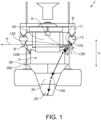
FIG. 1 is a view for describing one example of an overall configuration of an article processing apparatus according to one embodiment; -
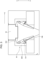
FIG. 2 is a view for describing one example of a hopper of the article processing apparatus according to one embodiment; -
FIG. 3 is a view for describing one example of a leg portion of the article processing apparatus according to one embodiment; -
FIG. 4 is a view for describing one example of a positional relationship between the hopper and the leg portion of the article processing apparatus according to one embodiment; -
FIG. 5 is a view for describing one example of a slide surface of a slide portion of the hopper of the article processing apparatus according to one embodiment; -
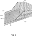
FIG. 6 is a view for describing one example of a side cover of the hopper of the article processing apparatus according to one embodiment; and -
FIG. 7 is a view for describing one example of an inside of a body portion of the hopper of the article processing apparatus according to one embodiment. - Hereinafter, the present embodiment will be described in detail with reference to the attached drawings. In the following description of the drawings, the same or similar parts are denoted by the same or similar reference symbols. However, note that the drawings are schematic, and ratios of dimensions are different from actual ones. Therefore, specific dimensions and the like are determined in consideration of the following description. Moreover, there may be portions where dimensional relationships or proportions are different among the drawings. In this specification and the drawings, elements having substantially the same function and configuration are denoted by the same reference numerals to omit redundant description, and elements not directly related to the present invention are omitted.
- Hereinafter, an article processing apparatus 1 according to a first embodiment of the present invention will be described with reference to
FIGS. 1 to 7 . - In the present embodiment, a case where the article processing apparatus 1 is a weighing device configured to weigh mass values of articles using a Roberval mechanism will be described as an example, but the present invention is not limited to such a case.
- As illustrated in
FIG. 1 , the article processing apparatus 1 according to the present embodiment includes a plurality ofpool hoppers 11, a plurality of weighinghoppers 12, and achute 30. - The articles supplied from a trough (not illustrated) temporarily stay in the
pool hoppers 11. Gates (not illustrated) are provided at lower portions of therespective pool hoppers 11, and when the gates are opened and closed, the articles (object to be weighted) staying in thepool hoppers 11 are discharged to the weighinghoppers 12 provided below the gates. - For example, such articles are food articles that are prolate ellipsoidal objects like rugby balls, such as baby carrots, gummies, and wieners. However, the articles are not limited to these.
- The articles discharged by the
pool hoppers 11 temporarily stay in the weighinghoppers 12.Gates 12C (to be described later) are provided at lower portions of therespective weighing hoppers 12, and when thegates 12C are opened and closed, the articles staying in the weighinghoppers 12 are discharged to a discharge opening 20 on a downstream side of the weighinghoppers 12. - Here, it is assumed that the plurality of
pool hoppers 11 and the plurality of weighinghoppers 12 are disposed in a circular shape. - As illustrated in
FIG. 2 , each of the plurality of weighinghoppers 12 includes abody portion 12A, aslide portion 12B, and thegate 12C. - The
slide portion 12B is provided on a downstream side of thebody portion 12A, and has aslide surface 120 extending continuously from thebody portion 12A. - The
gate 12C is provided on thebody portion 12A to switch between a first state where thegate 12C causesarticles 100 to stay in thebody portion 12A and a second state where thegate 12C releases the staying of thearticles 100 to cause thearticles 100 to slide down from thebody portion 12A. Thegate 12C is a gate that opens and closes inward with respect to the article processing apparatus 1. - Here, as illustrated in
FIG. 1 , theslide portion 12B has a length L or an angle A with respect to a horizontal direction H of a path along which thearticles 100 slide down theslide surface 120, take off from adownstream end portion 120E, freely fall in a space S where theslide surface 120 does not exist, and then reach the discharge opening 20, in the second state described above. - Namely, in the article processing apparatus 1 according to the present embodiment, in order to cause the
articles 100 to fall without contacting thechute 30 as much as possible, the length L of theslide surface 120 is set to be longer than in an article processing apparatus of the related art. - In addition, in the article processing apparatus 1 according to the present embodiment, in order to keep the height down low, the angle A with respect to the horizontal direction H is set to be smaller than in the article processing apparatus of the related art.
- Incidentally, the space S represents a path connecting the
downstream end portion 120E of theslide portion 12B and the discharge opening 20, and in such a path (space S), nothing exists that interferes with the free fall of thearticles 100. - According to such a configuration, since the
articles 100 can freely fall from theslide surface 120 in the space S and reach the discharge opening 20, the bouncing of thearticles 100 inside thechute 30 can be suppressed, and high-speed weighing can be realized. - In addition, according to such a configuration, the height of the article processing apparatus 1 can be kept down low by reducing the angle A with respect to the horizontal direction H.
- In addition, as illustrated in
FIG. 1 , thechute 30 may be disposed around thedischarge opening 20 in a state where thechute 30 is separated from thehopper 12 by the space S where theslide surface 120 does not exist in a vertical direction V. - Here, as illustrated in
FIG. 1 , in a side view of the article processing apparatus 1, left andright end portions 30E of thechute 30 may be located between thedownstream end portion 120E of theslide portion 12B and a boundary B between thebody portion 12A and theslide portion 12B. - According to such a configuration, since the left and
right end portions 30E of thechute 30 are disposed outside thedownstream end portion 120E of theslide portion 12B, a situation where thearticles 100 spill over the outside of thechute 30 can be avoided as much as possible. - In addition, according to such a configuration, since the left and
right end portions 30E of thechute 30 are disposed inside the boundary B between thebody portion 12A and theslide portion 12B, the space S described above can be secured, and cleanability and workability can be improved. - In addition, according to such a configuration, a chute of a size according to the related art is not required, and the
chute 30 of a minimum required size may be simply prepared, so that the cost can be reduced. - In addition, as illustrated in
FIG. 1 , the article processing apparatus 1 according to the present embodiment may include abody 50 to which the plurality ofpool hoppers 11 and the plurality of weighinghoppers 12 are attached, and a plurality of theleg portions 60 attached to thebody 50. - Here, as illustrated in
FIG. 3 , each of the plurality ofleg portions 60 may include afirst portion 60A extending outward from thebody 50, and asecond portion 60B extending downward from thefirst portion 60A. - Incidentally, the
first portion 60A may be configured to rise upward as extending outward. - According to such a configuration, since the length of the
second portion 60B can be shortened, the height of the article processing apparatus 1 can be kept down. - In addition, according to such a configuration, the height of the article processing apparatus 1 can be kept down low in a state where the rigidity of the
leg portions 60 is secured. - As illustrated in
FIG. 4 , thedownstream end portion 120E of theslide portion 12B may be disposed below a lower surface 60A1 of the first portion of each of theleg portions 60. - Here, as illustrated in
FIG. 4 , thefirst portion 60A may extend to the outside of thedownstream end portion 120E of theslide portion 12B, and thesecond portion 60B may extend downward outside thedownstream end portion 120E of theslide portion 12B. - According to such a configuration, a situation where the
articles 100 falling from thedownstream end portion 120E of theslide portion 12B collide with the lower surfaces 60A1 of the first portions of theleg portions 60 can be avoided. - As illustrated in
FIG. 5 , theslide surface 120 may have a shape extending downward from an outside O toward a central portion C in a width direction W. For example, theslide surface 120 may have a V shape as illustrated inFIG. 5 . - In the article processing apparatus 1 according to the present embodiment, since the angle A of the
slide surface 120 with respect to the horizontal direction H described above is reduced, the sliding of thearticles 100 becomes worse due to friction between thearticles 100 and each of aside surface 121B and aside cover 13 to be described later. Therefore, such a configuration is used, the friction between thearticles 100 and each of theside surface 121B and theside cover 13 to be described later can be reduced, and the sliding of thearticles 100 can be improved. - As illustrated in
FIG. 6 , theslide portion 12B may include theside cover 13 that stands from at least a part of bothside edges 120S of theslide surface 120. - Here, the
slide portion 12B may include theside cover 13 over the total length of both theside edges 120S of theslide surface 120, or may include theside cover 13 at both theside edges 120S of theslide surface 120 in the vicinity of a boundary B1 between thegate 12C and theslide portion 12B. - A height of the
side cover 13 may be constant. Alternatively, as illustrated inFIG. 6 , a height of theside cover 13 in the vicinity of the boundary B1 between thegate 12C and theslide portion 12B may be higher than a height of theside cover 13 at other portions. - In addition, the
side cover 13 may be formed by extending theside surface 121B (refer toFIG. 7 ) of thebody portion 12A, or may be provided separately from theside surface 121B of thebody portion 12A. - According to such a configuration, the
articles 100 can be prevented from falling from both the side edges 120S of theslide surface 120 to the outside. - As illustrated in
FIG. 7 , embossing may be applied to theside surface 121B of thebody portion 12A. Here, theside surface 121B of thebody portion 12A may have a region X to which embossing is not applied, in the vicinity of the boundary B1 between thegate 12C and theslide portion 12B. - Here, the region X may be generated by crushing some of the embossing applied to the
side surface 121B of thebody portion 12A or by welding a flat plate for flattening. - In the article processing apparatus 1 according to the present embodiment, since the angle A of the
slide surface 120 with respect to the horizontal direction H described above is reduced, there is a high possibility of the occurrence of a state called a bridge state where thearticles 100 are caught on the embossing provided on theside surface 121B of thebody portion 12A. - According to such a configuration, since the region X is provided in the vicinity of the boundary B1 between the
gate 12C and theslide portion 12B where such a bridge state is most likely to occur, the occurrence of such a bridge state can be suppressed. - Incidentally, as illustrated in
FIG. 6 , embossing may be applied to theside cover 13. Here, theside cover 13 may have a region to which embossing is not applied, in the vicinity of the boundary B1 between thegate 12C and theslide portion 12B. - According to such a configuration, similarly to the
side surface 121B of thebody portion 12A, the occurrence of the above-described bridge state can be suppressed. - As illustrated in
FIG. 7 , a length L1 of a conveyingsurface 121A for thearticles 100 in the width direction W in the vicinity of the boundary B1 between thegate 12C and theslide portion 12B may be set to be longer than a length L2 of the conveyingsurface 121A for thearticles 100 in the width direction W at a portion upstream of the boundary B1. - Namely, the conveying
surface 121A for thearticles 100 may have a reversed tapered shape (shape with a thick tip) in which the length in the width direction W increases from an upstream side toward a downstream side inside thebody portion 12A. - According to such a configuration, even when the
articles 100 are caught on theside surface 121B of thebody portion 12A somewhere on the conveyingsurface 121A for thearticles 100, since the length of the conveyingsurface 121A for thearticles 100 in the width direction W increases toward the downstream side, the articles easily come off from theside surface 121B of thebody portion 12A, so that the occurrence of the above-described bridge state can be suppressed. - Here, similarly to the
slide surface 120, the conveyingsurface 121A for thearticles 100 may have a shape extending downward from the outside O toward the central portion C in the width direction W. - In the article processing apparatus 1 according to the present embodiment, high-speed weighing can be performed, and the height can be kept down low.
- Although the present invention is explained in detail using the above-mentioned embodiments, it will be apparent to those skilled in the art that the present invention is not limited to the embodiments described herein. The present invention can be implemented as modifications and changes without departing from the spirit and scope of the present invention defined by the description of the claims. Accordingly, the description of the present specification is for the purpose of illustration and is not intended to limit the present invention in any way.
-
- 1
- article processing apparatus
- 12
- hopper
- 12A
- body portion
- 12B
- slide portion
- 12C
- gate
- 13
- side cover
- 20
- discharge opening
- 30
- chute
- 50
- body
- 60
- leg portion
- 60A
- first portion
- 60B
- second portion
- 100
- article
- 120
- slide surface
Claims (9)
- An article processing apparatus in which a plurality of hoppers are disposed in a circular shape and each of the plurality of hoppers causes an article received from an upstream side to temporarily stay and then discharges the article toward a discharge opening on a downstream side, whereineach of the hoppers includes:a body portion;a slide portion provided on a downstream side of the body portion, and having a slide surface extending continuously from the body portion; anda gate provided on the body portion to switch between a first state where the gate causes the article to stay in the body portion and a second state where the gate releases the staying of the article to cause the article to slide down from the body portion, andthe slide portion has a length or an angle with respect to a horizontal direction of a path along which the article slides down the slide surface, takes off from a downstream end portion of the slide portion, freely falls in a space where the slide surface does not exist, and then reaches the discharge opening, in the second state.
- The article processing apparatus according to claim 1, further comprising:a chute disposed around the discharge opening in a state where the chute is separate from the hoppers by the space where the slide surface does not exist in a vertical direction, whereinin a side view of the article processing apparatus, left and right end portions of the chute are located between the downstream end portion of the slide portion and a boundary between the body portion and the slide portion.
- The article processing apparatus according to claim 1 or 2, further comprising:a body to which the plurality of hoppers are attached; anda plurality of leg portions attached to the body, whereineach of the plurality of leg portions includes:a first portion extending outward from the body; anda second portion extending downward from the first portion.
- The article processing apparatus according to claim 3, wherein
the downstream end portion of the slide portion is located below a lower surface of the first portion of each of the leg portions. - The article processing apparatus according to any one of claims 1 to 4, wherein
the slide surface has a shape extending downward from an outside toward a central portion in a width direction. - The article processing apparatus according to any one of claims 1 to 4, wherein
the slide portion includes a side cover that stands from at least a part of both side edges of the slide surface. - The article processing apparatus according to any one of claims 1 to 6, whereinembossing is applied to a side surface of the body portion, andthe side surface of the body portion has a region to which the embossing is not applied, in the vicinity of a boundary between the gate and the body portion.
- The article processing apparatus according to claim 6, whereinembossing is applied to the side cover, andthe side cover has a region to which embossing is not applied, in the vicinity of a boundary between the gate and the slide portion.
- The article processing apparatus according to any one of claims 1 to 8, wherein
a length of a conveying surface for the article in a width direction in the vicinity of a boundary between the gate and the slide portion is longer than a length of the conveying surface for the article in the width direction at a portion upstream of the boundary.
Applications Claiming Priority (1)
| Application Number | Priority Date | Filing Date | Title |
|---|---|---|---|
| JP2021176170A JP7818802B2 (en) | 2021-10-28 | 2021-10-28 | Item handling equipment |
Publications (2)
| Publication Number | Publication Date |
|---|---|
| EP4174456A1 true EP4174456A1 (en) | 2023-05-03 |
| EP4174456B1 EP4174456B1 (en) | 2024-09-25 |
Family
ID=83689061
Family Applications (1)
| Application Number | Title | Priority Date | Filing Date |
|---|---|---|---|
| EP22200150.5A Active EP4174456B1 (en) | 2021-10-28 | 2022-10-06 | Article processing apparatus |
Country Status (5)
| Country | Link |
|---|---|
| US (1) | US12012279B2 (en) |
| EP (1) | EP4174456B1 (en) |
| JP (1) | JP7818802B2 (en) |
| CN (1) | CN116046130B (en) |
| DK (1) | DK4174456T3 (en) |
Citations (2)
| Publication number | Priority date | Publication date | Assignee | Title |
|---|---|---|---|---|
| JP2009258040A (en) * | 2008-04-21 | 2009-11-05 | Ishida Co Ltd | Combination weighing device |
| JP2021021609A (en) | 2019-07-26 | 2021-02-18 | 大和製衡株式会社 | Combination balance |
Family Cites Families (22)
| Publication number | Priority date | Publication date | Assignee | Title |
|---|---|---|---|---|
| US748494A (en) * | 1903-06-25 | 1903-12-29 | William Q Gansen | Dispenser for powdered material. |
| US1359730A (en) * | 1920-02-02 | 1920-11-23 | Fred B Norton | Measuring-funnel |
| US4337943A (en) * | 1978-10-06 | 1982-07-06 | Gilbert Stewart | Cue ball shooting guide |
| LU86336A1 (en) * | 1986-03-04 | 1987-11-11 | Wurth Paul Sa | LOADING SYSTEM FOR A TANK OVEN |
| CH683562A5 (en) * | 1992-05-05 | 1994-03-31 | K Tron Tech Inc | Bulk scale. |
| US5339996A (en) * | 1993-04-26 | 1994-08-23 | Midwest Pre-Mix, Inc. | Portable mini silo system |
| AU2339095A (en) * | 1994-07-11 | 1996-01-25 | Matcon Limited | Material handling apparatus |
| IT1276686B1 (en) * | 1995-06-08 | 1997-11-03 | Simionato Spa | SET OF WEIGHING BASKETS IN A PACKAGING MACHINE |
| JP2000292245A (en) | 1999-04-07 | 2000-10-20 | Yamato Scale Co Ltd | Hopper for weighing machine |
| JP2001349768A (en) | 2000-06-07 | 2001-12-21 | Anritsu Corp | Combined measuring instrument |
| JP4170711B2 (en) | 2002-09-02 | 2008-10-22 | 株式会社イシダ | Combination weigher |
| JP4173412B2 (en) * | 2003-08-06 | 2008-10-29 | 株式会社イシダ | Combination weighing device |
| JP2006078241A (en) | 2004-09-08 | 2006-03-23 | Ishida Co Ltd | Hopper and weighing device equipped with the hopper |
| JP4781801B2 (en) * | 2005-12-01 | 2011-09-28 | 株式会社イシダ | Weighing device |
| JP2007303846A (en) | 2006-05-09 | 2007-11-22 | Ishida Co Ltd | Weighing device |
| JP5509435B2 (en) * | 2007-03-02 | 2014-06-04 | 株式会社イシダ | Double hopper, hopper unit and combination weighing device |
| JP2012141294A (en) * | 2010-12-13 | 2012-07-26 | Ishida Co Ltd | Weighing apparatus |
| JP6066814B2 (en) | 2013-04-23 | 2017-01-25 | 大和製衡株式会社 | Combination scale |
| EP3255394B1 (en) * | 2015-02-04 | 2021-09-08 | Ishida Co., Ltd. | Combination weighing device |
| WO2020003409A1 (en) * | 2018-06-27 | 2020-01-02 | 大和製衡株式会社 | Alignment and transport device |
| JP2020001891A (en) | 2018-06-28 | 2020-01-09 | 株式会社イシダ | Transport feeder |
| GB2592000B (en) * | 2020-02-05 | 2022-08-24 | Schenck Process Europe Gmbh | Hopper for feeding bulk material |
-
2021
- 2021-10-28 JP JP2021176170A patent/JP7818802B2/en active Active
-
2022
- 2022-10-06 DK DK22200150.5T patent/DK4174456T3/en active
- 2022-10-06 EP EP22200150.5A patent/EP4174456B1/en active Active
- 2022-10-20 US US18/048,402 patent/US12012279B2/en active Active
- 2022-10-24 CN CN202211303637.9A patent/CN116046130B/en active Active
Patent Citations (2)
| Publication number | Priority date | Publication date | Assignee | Title |
|---|---|---|---|---|
| JP2009258040A (en) * | 2008-04-21 | 2009-11-05 | Ishida Co Ltd | Combination weighing device |
| JP2021021609A (en) | 2019-07-26 | 2021-02-18 | 大和製衡株式会社 | Combination balance |
Also Published As
| Publication number | Publication date |
|---|---|
| DK4174456T3 (en) | 2024-09-30 |
| CN116046130B (en) | 2025-09-12 |
| CN116046130A (en) | 2023-05-02 |
| EP4174456B1 (en) | 2024-09-25 |
| JP7818802B2 (en) | 2026-02-24 |
| JP2023065814A (en) | 2023-05-15 |
| US20230133121A1 (en) | 2023-05-04 |
| US12012279B2 (en) | 2024-06-18 |
Similar Documents
| Publication | Publication Date | Title |
|---|---|---|
| US10801880B2 (en) | Combination weighing device with hoppers and discharge chutes having complementary surfaces | |
| EP4174456B1 (en) | Article processing apparatus | |
| US11927470B2 (en) | Combination weighing apparatus with discharge chute including slide surface | |
| US10794755B2 (en) | Combination weighing device with discharge chutes having receiving and sliding surfaces of varying widths | |
| EP4140918A1 (en) | Conveyance apparatus | |
| US11975923B2 (en) | Article retaining device and supporting body | |
| US5213199A (en) | Chain arrangement for drag-chain conveyors | |
| CN102653345B (en) | Workpiece handling device | |
| JP3193858U (en) | X-ray shielding noren and X-ray inspection apparatus equipped with the same | |
| US20240308772A1 (en) | Combination weighing apparatus | |
| JPH04112124A (en) | Article sorting device | |
| US20210070560A1 (en) | Timing hopper and combination weighing device | |
| CN206857659U (en) | A kind of material transmission receiving hopper | |
| KR101928179B1 (en) | Apparatus for preventing fallen ore of tripper car | |
| JP7200001B2 (en) | X-ray inspection device | |
| JP2957453B2 (en) | Conveyance movement buffer | |
| US12006161B2 (en) | Centering device for objects to be conveyed, and packaging device for packaging materials equipped with same | |
| KR20030035528A (en) | The Convey System for Preventing Material from Falling on the Outside of Conveying Line | |
| US12600578B2 (en) | Supply apparatus | |
| US11274959B2 (en) | Weighing apparatus and combination weighing apparatus | |
| JPH0741122A (en) | Reduction gear mechanism for ic conveyer rail in handler of semiconductor tester | |
| JPH072224A (en) | Coin accumulating device | |
| JP2005221272A (en) | Weighing hopper |
Legal Events
| Date | Code | Title | Description |
|---|---|---|---|
| PUAI | Public reference made under article 153(3) epc to a published international application that has entered the european phase |
Free format text: ORIGINAL CODE: 0009012 |
|
| STAA | Information on the status of an ep patent application or granted ep patent |
Free format text: STATUS: REQUEST FOR EXAMINATION WAS MADE |
|
| 17P | Request for examination filed |
Effective date: 20221006 |
|
| AK | Designated contracting states |
Kind code of ref document: A1 Designated state(s): AL AT BE BG CH CY CZ DE DK EE ES FI FR GB GR HR HU IE IS IT LI LT LU LV MC ME MK MT NL NO PL PT RO RS SE SI SK SM TR |
|
| GRAP | Despatch of communication of intention to grant a patent |
Free format text: ORIGINAL CODE: EPIDOSNIGR1 |
|
| STAA | Information on the status of an ep patent application or granted ep patent |
Free format text: STATUS: GRANT OF PATENT IS INTENDED |
|
| INTG | Intention to grant announced |
Effective date: 20240416 |
|
| GRAS | Grant fee paid |
Free format text: ORIGINAL CODE: EPIDOSNIGR3 |
|
| GRAA | (expected) grant |
Free format text: ORIGINAL CODE: 0009210 |
|
| STAA | Information on the status of an ep patent application or granted ep patent |
Free format text: STATUS: THE PATENT HAS BEEN GRANTED |
|
| AK | Designated contracting states |
Kind code of ref document: B1 Designated state(s): AL AT BE BG CH CY CZ DE DK EE ES FI FR GB GR HR HU IE IS IT LI LT LU LV MC ME MK MT NL NO PL PT RO RS SE SI SK SM TR |
|
| REG | Reference to a national code |
Ref country code: GB Ref legal event code: FG4D |
|
| REG | Reference to a national code |
Ref country code: CH Ref legal event code: EP Ref country code: DK Ref legal event code: T3 Effective date: 20240927 |
|
| REG | Reference to a national code |
Ref country code: DE Ref legal event code: R096 Ref document number: 602022006349 Country of ref document: DE |
|
| REG | Reference to a national code |
Ref country code: IE Ref legal event code: FG4D |
|
| REG | Reference to a national code |
Ref country code: LT Ref legal event code: MG9D |
|
| PG25 | Lapsed in a contracting state [announced via postgrant information from national office to epo] |
Ref country code: NO Free format text: LAPSE BECAUSE OF FAILURE TO SUBMIT A TRANSLATION OF THE DESCRIPTION OR TO PAY THE FEE WITHIN THE PRESCRIBED TIME-LIMIT Effective date: 20241225 |
|
| PG25 | Lapsed in a contracting state [announced via postgrant information from national office to epo] |
Ref country code: GR Free format text: LAPSE BECAUSE OF FAILURE TO SUBMIT A TRANSLATION OF THE DESCRIPTION OR TO PAY THE FEE WITHIN THE PRESCRIBED TIME-LIMIT Effective date: 20241226 Ref country code: FI Free format text: LAPSE BECAUSE OF FAILURE TO SUBMIT A TRANSLATION OF THE DESCRIPTION OR TO PAY THE FEE WITHIN THE PRESCRIBED TIME-LIMIT Effective date: 20240925 |
|
| PG25 | Lapsed in a contracting state [announced via postgrant information from national office to epo] |
Ref country code: BG Free format text: LAPSE BECAUSE OF FAILURE TO SUBMIT A TRANSLATION OF THE DESCRIPTION OR TO PAY THE FEE WITHIN THE PRESCRIBED TIME-LIMIT Effective date: 20240925 |
|
| PG25 | Lapsed in a contracting state [announced via postgrant information from national office to epo] |
Ref country code: LV Free format text: LAPSE BECAUSE OF FAILURE TO SUBMIT A TRANSLATION OF THE DESCRIPTION OR TO PAY THE FEE WITHIN THE PRESCRIBED TIME-LIMIT Effective date: 20240925 |
|
| PG25 | Lapsed in a contracting state [announced via postgrant information from national office to epo] |
Ref country code: RS Free format text: LAPSE BECAUSE OF FAILURE TO SUBMIT A TRANSLATION OF THE DESCRIPTION OR TO PAY THE FEE WITHIN THE PRESCRIBED TIME-LIMIT Effective date: 20241225 |
|
| REG | Reference to a national code |
Ref country code: NL Ref legal event code: MP Effective date: 20240925 |
|
| PG25 | Lapsed in a contracting state [announced via postgrant information from national office to epo] |
Ref country code: RS Free format text: LAPSE BECAUSE OF FAILURE TO SUBMIT A TRANSLATION OF THE DESCRIPTION OR TO PAY THE FEE WITHIN THE PRESCRIBED TIME-LIMIT Effective date: 20241225 Ref country code: NO Free format text: LAPSE BECAUSE OF FAILURE TO SUBMIT A TRANSLATION OF THE DESCRIPTION OR TO PAY THE FEE WITHIN THE PRESCRIBED TIME-LIMIT Effective date: 20241225 Ref country code: LV Free format text: LAPSE BECAUSE OF FAILURE TO SUBMIT A TRANSLATION OF THE DESCRIPTION OR TO PAY THE FEE WITHIN THE PRESCRIBED TIME-LIMIT Effective date: 20240925 Ref country code: GR Free format text: LAPSE BECAUSE OF FAILURE TO SUBMIT A TRANSLATION OF THE DESCRIPTION OR TO PAY THE FEE WITHIN THE PRESCRIBED TIME-LIMIT Effective date: 20241226 Ref country code: FI Free format text: LAPSE BECAUSE OF FAILURE TO SUBMIT A TRANSLATION OF THE DESCRIPTION OR TO PAY THE FEE WITHIN THE PRESCRIBED TIME-LIMIT Effective date: 20240925 Ref country code: BG Free format text: LAPSE BECAUSE OF FAILURE TO SUBMIT A TRANSLATION OF THE DESCRIPTION OR TO PAY THE FEE WITHIN THE PRESCRIBED TIME-LIMIT Effective date: 20240925 |
|
| REG | Reference to a national code |
Ref country code: AT Ref legal event code: MK05 Ref document number: 1726977 Country of ref document: AT Kind code of ref document: T Effective date: 20240925 |
|
| PG25 | Lapsed in a contracting state [announced via postgrant information from national office to epo] |
Ref country code: NL Free format text: LAPSE BECAUSE OF FAILURE TO SUBMIT A TRANSLATION OF THE DESCRIPTION OR TO PAY THE FEE WITHIN THE PRESCRIBED TIME-LIMIT Effective date: 20240925 |
|
| PG25 | Lapsed in a contracting state [announced via postgrant information from national office to epo] |
Ref country code: IS Free format text: LAPSE BECAUSE OF FAILURE TO SUBMIT A TRANSLATION OF THE DESCRIPTION OR TO PAY THE FEE WITHIN THE PRESCRIBED TIME-LIMIT Effective date: 20250125 Ref country code: PT Free format text: LAPSE BECAUSE OF FAILURE TO SUBMIT A TRANSLATION OF THE DESCRIPTION OR TO PAY THE FEE WITHIN THE PRESCRIBED TIME-LIMIT Effective date: 20250127 |
|
| PG25 | Lapsed in a contracting state [announced via postgrant information from national office to epo] |
Ref country code: RO Free format text: LAPSE BECAUSE OF FAILURE TO SUBMIT A TRANSLATION OF THE DESCRIPTION OR TO PAY THE FEE WITHIN THE PRESCRIBED TIME-LIMIT Effective date: 20240925 Ref country code: SM Free format text: LAPSE BECAUSE OF FAILURE TO SUBMIT A TRANSLATION OF THE DESCRIPTION OR TO PAY THE FEE WITHIN THE PRESCRIBED TIME-LIMIT Effective date: 20240925 |
|
| PG25 | Lapsed in a contracting state [announced via postgrant information from national office to epo] |
Ref country code: ES Free format text: LAPSE BECAUSE OF FAILURE TO SUBMIT A TRANSLATION OF THE DESCRIPTION OR TO PAY THE FEE WITHIN THE PRESCRIBED TIME-LIMIT Effective date: 20240925 |
|
| PG25 | Lapsed in a contracting state [announced via postgrant information from national office to epo] |
Ref country code: AT Free format text: LAPSE BECAUSE OF FAILURE TO SUBMIT A TRANSLATION OF THE DESCRIPTION OR TO PAY THE FEE WITHIN THE PRESCRIBED TIME-LIMIT Effective date: 20240925 Ref country code: EE Free format text: LAPSE BECAUSE OF FAILURE TO SUBMIT A TRANSLATION OF THE DESCRIPTION OR TO PAY THE FEE WITHIN THE PRESCRIBED TIME-LIMIT Effective date: 20240925 |
|
| PG25 | Lapsed in a contracting state [announced via postgrant information from national office to epo] |
Ref country code: CZ Free format text: LAPSE BECAUSE OF FAILURE TO SUBMIT A TRANSLATION OF THE DESCRIPTION OR TO PAY THE FEE WITHIN THE PRESCRIBED TIME-LIMIT Effective date: 20240925 Ref country code: PL Free format text: LAPSE BECAUSE OF FAILURE TO SUBMIT A TRANSLATION OF THE DESCRIPTION OR TO PAY THE FEE WITHIN THE PRESCRIBED TIME-LIMIT Effective date: 20240925 |
|
| PG25 | Lapsed in a contracting state [announced via postgrant information from national office to epo] |
Ref country code: IT Free format text: LAPSE BECAUSE OF FAILURE TO SUBMIT A TRANSLATION OF THE DESCRIPTION OR TO PAY THE FEE WITHIN THE PRESCRIBED TIME-LIMIT Effective date: 20240925 Ref country code: SK Free format text: LAPSE BECAUSE OF FAILURE TO SUBMIT A TRANSLATION OF THE DESCRIPTION OR TO PAY THE FEE WITHIN THE PRESCRIBED TIME-LIMIT Effective date: 20240925 |
|
| REG | Reference to a national code |
Ref country code: DE Ref legal event code: R097 Ref document number: 602022006349 Country of ref document: DE |
|
| PG25 | Lapsed in a contracting state [announced via postgrant information from national office to epo] |
Ref country code: MC Free format text: LAPSE BECAUSE OF FAILURE TO SUBMIT A TRANSLATION OF THE DESCRIPTION OR TO PAY THE FEE WITHIN THE PRESCRIBED TIME-LIMIT Effective date: 20240925 |
|
| PG25 | Lapsed in a contracting state [announced via postgrant information from national office to epo] |
Ref country code: LU Free format text: LAPSE BECAUSE OF NON-PAYMENT OF DUE FEES Effective date: 20241006 Ref country code: BE Free format text: LAPSE BECAUSE OF NON-PAYMENT OF DUE FEES Effective date: 20241031 |
|
| PLBE | No opposition filed within time limit |
Free format text: ORIGINAL CODE: 0009261 |
|
| STAA | Information on the status of an ep patent application or granted ep patent |
Free format text: STATUS: NO OPPOSITION FILED WITHIN TIME LIMIT |
|
| REG | Reference to a national code |
Ref country code: BE Ref legal event code: MM Effective date: 20241031 |
|
| 26N | No opposition filed |
Effective date: 20250626 |
|
| PG25 | Lapsed in a contracting state [announced via postgrant information from national office to epo] |
Ref country code: SE Free format text: LAPSE BECAUSE OF FAILURE TO SUBMIT A TRANSLATION OF THE DESCRIPTION OR TO PAY THE FEE WITHIN THE PRESCRIBED TIME-LIMIT Effective date: 20240925 |
|
| PG25 | Lapsed in a contracting state [announced via postgrant information from national office to epo] |
Ref country code: FR Free format text: LAPSE BECAUSE OF NON-PAYMENT OF DUE FEES Effective date: 20241125 |
|
| PG25 | Lapsed in a contracting state [announced via postgrant information from national office to epo] |
Ref country code: IE Free format text: LAPSE BECAUSE OF NON-PAYMENT OF DUE FEES Effective date: 20241006 |
|
| PGFP | Annual fee paid to national office [announced via postgrant information from national office to epo] |
Ref country code: DE Payment date: 20251020 Year of fee payment: 4 |
|
| PGFP | Annual fee paid to national office [announced via postgrant information from national office to epo] |
Ref country code: DK Payment date: 20251023 Year of fee payment: 4 |
|
| PG25 | Lapsed in a contracting state [announced via postgrant information from national office to epo] |
Ref country code: HR Free format text: LAPSE BECAUSE OF FAILURE TO SUBMIT A TRANSLATION OF THE DESCRIPTION OR TO PAY THE FEE WITHIN THE PRESCRIBED TIME-LIMIT Effective date: 20240925 |
|
| PG25 | Lapsed in a contracting state [announced via postgrant information from national office to epo] |
Ref country code: CY Free format text: LAPSE BECAUSE OF FAILURE TO SUBMIT A TRANSLATION OF THE DESCRIPTION OR TO PAY THE FEE WITHIN THE PRESCRIBED TIME-LIMIT; INVALID AB INITIO Effective date: 20221006 |
|
| PG25 | Lapsed in a contracting state [announced via postgrant information from national office to epo] |
Ref country code: HU Free format text: LAPSE BECAUSE OF FAILURE TO SUBMIT A TRANSLATION OF THE DESCRIPTION OR TO PAY THE FEE WITHIN THE PRESCRIBED TIME-LIMIT; INVALID AB INITIO Effective date: 20221006 |