EP4174453B1 - Ray transceiving system of underwater flowmeter and deduction metering method - Google Patents
Ray transceiving system of underwater flowmeter and deduction metering method Download PDFInfo
- Publication number
- EP4174453B1 EP4174453B1 EP22187955.4A EP22187955A EP4174453B1 EP 4174453 B1 EP4174453 B1 EP 4174453B1 EP 22187955 A EP22187955 A EP 22187955A EP 4174453 B1 EP4174453 B1 EP 4174453B1
- Authority
- EP
- European Patent Office
- Prior art keywords
- deduction
- measured
- gamma
- ray
- beryllium
- Prior art date
- Legal status (The legal status is an assumption and is not a legal conclusion. Google has not performed a legal analysis and makes no representation as to the accuracy of the status listed.)
- Active
Links
Images
Classifications
-
- G—PHYSICS
- G01—MEASURING; TESTING
- G01F—MEASURING VOLUME, VOLUME FLOW, MASS FLOW OR LIQUID LEVEL; METERING BY VOLUME
- G01F1/00—Measuring the volume flow or mass flow of fluid or fluent solid material wherein the fluid passes through a meter in a continuous flow
- G01F1/704—Measuring the volume flow or mass flow of fluid or fluent solid material wherein the fluid passes through a meter in a continuous flow using marked regions or existing inhomogeneities within the fluid stream, e.g. statistically occurring variations in a fluid parameter
- G01F1/7042—Measuring the volume flow or mass flow of fluid or fluent solid material wherein the fluid passes through a meter in a continuous flow using marked regions or existing inhomogeneities within the fluid stream, e.g. statistically occurring variations in a fluid parameter using radioactive tracers
-
- G—PHYSICS
- G01—MEASURING; TESTING
- G01F—MEASURING VOLUME, VOLUME FLOW, MASS FLOW OR LIQUID LEVEL; METERING BY VOLUME
- G01F1/00—Measuring the volume flow or mass flow of fluid or fluent solid material wherein the fluid passes through a meter in a continuous flow
- G01F1/66—Measuring the volume flow or mass flow of fluid or fluent solid material wherein the fluid passes through a meter in a continuous flow by measuring frequency, phase shift or propagation time of electromagnetic or other waves, e.g. using ultrasonic flowmeters
- G01F1/662—Constructional details
-
- G—PHYSICS
- G01—MEASURING; TESTING
- G01F—MEASURING VOLUME, VOLUME FLOW, MASS FLOW OR LIQUID LEVEL; METERING BY VOLUME
- G01F1/00—Measuring the volume flow or mass flow of fluid or fluent solid material wherein the fluid passes through a meter in a continuous flow
- G01F1/66—Measuring the volume flow or mass flow of fluid or fluent solid material wherein the fluid passes through a meter in a continuous flow by measuring frequency, phase shift or propagation time of electromagnetic or other waves, e.g. using ultrasonic flowmeters
-
- G—PHYSICS
- G01—MEASURING; TESTING
- G01F—MEASURING VOLUME, VOLUME FLOW, MASS FLOW OR LIQUID LEVEL; METERING BY VOLUME
- G01F1/00—Measuring the volume flow or mass flow of fluid or fluent solid material wherein the fluid passes through a meter in a continuous flow
- G01F1/74—Devices for measuring flow of a fluid or flow of a fluent solid material in suspension in another fluid
-
- G—PHYSICS
- G01—MEASURING; TESTING
- G01N—INVESTIGATING OR ANALYSING MATERIALS BY DETERMINING THEIR CHEMICAL OR PHYSICAL PROPERTIES
- G01N23/00—Investigating or analysing materials by the use of wave or particle radiation, e.g. X-rays or neutrons, not covered by groups G01N3/00 – G01N17/00, G01N21/00 or G01N22/00
- G01N23/02—Investigating or analysing materials by the use of wave or particle radiation, e.g. X-rays or neutrons, not covered by groups G01N3/00 – G01N17/00, G01N21/00 or G01N22/00 by transmitting the radiation through the material
- G01N23/06—Investigating or analysing materials by the use of wave or particle radiation, e.g. X-rays or neutrons, not covered by groups G01N3/00 – G01N17/00, G01N21/00 or G01N22/00 by transmitting the radiation through the material and measuring the absorption
- G01N23/12—Investigating or analysing materials by the use of wave or particle radiation, e.g. X-rays or neutrons, not covered by groups G01N3/00 – G01N17/00, G01N21/00 or G01N22/00 by transmitting the radiation through the material and measuring the absorption the material being a flowing fluid or a flowing granular solid
Definitions
- the present disclosure relates to equipment and methods for offshore petroleum engineering, and in particular, to underwater multi-phase flow metering equipment for offshore petroleum engineering.
- Chinese patent application (publication number: CN106706047A ; CN106768120A) submitted by the applicant in 2017 discloses the use of ceramic materials (first and second ceramic sealing gaskets) to seal a fluid metering channel to reduce the absorption of gamma rays, thereby improving the measurement accuracy of the three-phase flow of oil, gas and water.
- ceramic materials first and second ceramic sealing gaskets
- the ceramic materials have little resistance to the gamma rays, they have poor ductility, are difficult to process into special-shaped structures and easy to break, and cannot meet the requirements of 20-year service life and provide product reliability.
- CN 206 618 453 U discloses a similar prior art underwater flowmeter for multi-phase flows.
- Conventional sealing materials include steel and polyetheretherketone (PEEK).
- Steel has high density and will absorb too much gamma rays, making it impossible to measure, while the PEEK does not have sufficient strength to be matched with a metal sealing ring.
- Titanium alloy has high strength, is relatively easy to process and form, and has a density much lower than ordinary steel, making it an alternative.
- the thickness of the titanium alloy material is excessively large, it will still largely absorb gamma rays, which is unfavorable for improving the measurement accuracy of the three-phase flow of oil, gas and water.
- the heavy components inside titanium alloy scatter gamma rays largely.
- titanium alloy forms an obvious Compton effect on the ray spectrum (see Chinese patent applications with publication numbers: CN107436165A and CN107331429A ).
- the high-energy gamma ray ⁇ h is partially reduced to the energy level ⁇ l after the Compton scattering of the titanium alloy, which may coincide with the low-energy ray ⁇ l ' emitted by the gamma source itself, resulting in the distortion of the count rate obtained by the gamma probe, which deepens as the thickness of the titanium alloy penetrated by the gamma rays increases.
- the present disclosure firstly provides a ray transceiving system of an underwater flowmeter, which ensures the compressive strength and reduce the absorption of gamma rays with new material/material combination and structural design.
- a ray transceiving system of an underwater flowmeter includes a flowmeter body.
- a fluid metering channel extends through the flowmeter body.
- a transmitting window and a probing window positioned on both sides of the fluid metering channel are arranged on the flowmeter body.
- An inner end of the transmitting window and an inner end of the probing window are arranged opposite to each other and are respectively in communication with the fluid metering channel separately.
- a ray transmitting module is arranged in the transmitting window.
- a ray probing module is arranged in the probing window. The ray transmitting module transmits rays to pass through the fluid metering channel.
- the ray probing module probes and receives the rays passing through the fluid metering channel.
- the ray transmitting module includes a radioactive source assembly, a collimator, and a first isolation seat arranged in sequence.
- the first isolation seat is located at the inner end of the transmitting window.
- the first isolation seat separates and seals the fluid metering channel and the transmitting window.
- An inner end face of the first isolation seat is flush with and adapted to an inner wall of the fluid metering channel.
- the ray probing module includes a probe component, a pressing ring, and a second isolation seat arranged in sequence.
- the second isolation seat is located at the inner end of the probing window.
- the second isolation seat separates and seals the fluid metering channel and the probing window.
- An inner end face of the second isolation seat is flush with and adapted to the inner wall of the fluid metering channel.
- a first beryllium pad is arranged between the collimator and the first isolation seat, and the first isolation seat is made of titanium alloy.
- a second beryllium pad is arranged between the pressing ring and the second isolation seat, and the second isolation seat is made of titanium alloy.
- the titanium alloy and the metal beryllium are combined, and are installed and cooperate in a new structural form.
- the titanium alloy which is relatively easy to process and form is used to seal the fluid metering channel, the titanium alloy and the beryllium pad are combined to bear pressure, and the beryllium pad is used to reduce absorption of gamma rays, so as to solve the problems of inconvenient processing, short service life, and low reliability caused by material (ceramic) problems.
- the present disclosure continues to provide a deduction metering method of an underwater flowmeter on the basis of using the titanium alloy as a sealing material, which solves the problem of energy level coincidence caused by Compton scattering from the perspective of improving the accuracy of a gamma count rate, so as to improve the metering accuracy.
- the technical solutions are as follows:
- a deduction metering method of an underwater flowmeter includes the following steps:
- a count rate of the original low-energy level can be obtained by deducting a count rate of the detected scattering low-energy level on the gamma absorption spectrum.
- a ray transceiving system of an underwater flowmeter includes a flowmeter body 10.
- a fluid metering channel extends through the flowmeter body 10.
- the fluid metering channel is conventionally arranged as a circular hole type channel.
- a transmitting window and a probing window positioned on both sides of the fluid metering channel are arranged on the flowmeter body 10.
- An inner end of the transmitting window and an inner end of the probing window are arranged opposite to each other and are respectively in communication with the fluid metering channel separately.
- a ray transmitting module is arranged in the transmitting window.
- a ray probing module is arranged in the probing window. The ray transmitting module transmits rays to pass perpendicular to a hole center line of the fluid metering channel.
- the ray probing module probes and receives the rays passing through the fluid metering channel.
- the ray transmitting module includes a radioactive source assembly 21, a collimator 22, and a first isolation seat 24 arranged in sequence.
- the first isolation seat 24 is located at the inner end of the transmitting window.
- the first isolation seat 24 separates and seals the fluid metering channel and the transmitting window.
- An inner end face of the first isolation seat 24 is flush with and adapted to an inner wall of the fluid metering channel.
- the ray probing module includes a probe component 31, a pressing ring 32, and a second isolation seat 34 arranged in sequence.
- the second isolation seat 34 is located at the inner end of the probing window.
- the second isolation seat 34 separates and seals the fluid metering channel and the probing window.
- An inner end face of the second isolation seat 34 is flush with and adapted to the inner wall of the fluid metering channel.
- a first beryllium pad 23 is arranged between the collimator 22 and the first isolation seat 24, and the first isolation seat 24 is made of titanium alloy.
- a second beryllium pad 33 is arranged between the pressing ring 32 and the second isolation seat 34, and the second isolation seat 34 is made of titanium alloy.
- a surface of the first isolation seat 24 facing the collimator 22 is provided with a first embedded counterbore.
- the collimator 22 is provided with a first top piece 221 matched with the first embedded counterbore.
- the first top piece 221 is provided with a beryllium sheet insertion opening.
- the beryllium sheet insertion opening faces a bottom of the first embedded counterbore.
- the first beryllium pad 23 is embedded in and matched with the beryllium sheet insertion opening.
- the first top piece 221 is embedded in the first embedded counterbore.
- a protruding end of the first top piece 221 abuts against the bottom of the first embedded counterbore.
- the first beryllium pad 23 abuts against the bottom of the first embedded counterbore.
- a collimating hole 22a penetrates through the collimator 22.
- a hole center line of the collimating hole 22a is perpendicular to and intersects with the hole center line of the fluid metering channel.
- the collimating hole 22a includes two sections, one of which has a smaller hole diameter than the other.
- the small hole end of the collimating hole 22a faces the radioactive source assembly 21.
- the large hole end of the collimating hole 22a is in communication with the beryllium sheet insertion opening and faces the first beryllium pad 23.
- a surface of the second isolation seat 34 facing the pressing ring 32 is provided with a second embedded counterbore.
- the second beryllium pad 33 is embedded in and matched with the second embedded counterbore.
- the pressing ring 32 abuts both the second beryllium pad 33 and the second isolation seat 34.
- the second embedded counterbore includes a circular bore segment and a circular frustum bore segment.
- the circular bore segment is adjacent to the fluid metering channel.
- the circular frustum bore segment faces the pressing ring 32.
- the second beryllium pad 33 is embedded in the circular bore segment.
- An end face of the pressing ring 32 facing the second embedded counterbore is provided with a ring of pressing flange 321.
- the pressing flange 321 is arranged adjacent to an inner ring of the pressing ring 32.
- An inner ring of the pressing flange 321 is flush with the inner ring of the pressing ring 32.
- the pressing flange 321 is embedded in the circular frustum bore segment.
- An outer ring of the pressing flange 321 is adapted to and matched with a bore wall of the circular frustum bore segment.
- the pressing ring 32 and the pressing flange 321 are integrally formed.
- An arc-shaped transition is formed between an outer wall and two end faces of the outer ring of the pressing flange 321.
- An arc-shaped transition is formed between a large opening section and an end face are of the circular frustum bore segment to avoid stress concentration during pressure bearing and damage to the pressing ring 32 and the second isolation seat 34.
- An embedded end face of the pressing flange 321 abuts the second beryllium pad 33.
- the pressing ring 32 and the outer ring of the pressing flange 321 abut the second isolation seat 34.
- a thickness of the second beryllium pad 33 is greater than a thickness of the first beryllium pad 23.
- a deduction metering method of an underwater flowmeter includes the following steps.
- Step I the ray transceiving system of an underwater flowmeter according to Embodiment 1 is arranged.
- the fluid metering channel is penetrated using any two groups of energy levels of the radioactive source assembly 21.
- Gamma count rates N corresponding to a first energy level and a second energy level are respectively obtained by the probe component 31.
- the radioactive source assembly 21 can use a Ba-133 radioactive source assembly.
- the Ba-133 radioactive source mainly has three energy levels that can be used for flow measurement, namely 31 keV, 81 keV, and 356 keV respectively.
- the multi-phase flow is measured by using two energy levels of 31 keV and 81 keV of Ba-133.
- Step II a first empty tube count rate N 0 1 and a second empty tube count rate N 0 2 of the two groups of energy levels are measured by the probe component 31 under a condition of emptying the fluid metering channel.
- a three-phase mixed flow of oil, gas and water passes through the fluid metering channel, and a first measured count rate N x 1 and a second measured count rate N x 2 of the two groups of energy levels are measured by the probe component 31 respectively.
- Step III a first empty tube deduction value S 0 1 and a second empty tube deduction value S 0 2 are delineated on an empty tube gamma absorption spectrum.
- a first measured deduction value S x 1 and a second measured deduction value S x 2 are delineated on a measured gamma absorption spectrum.
- the first empty tube deduction value S 0 1 , the second empty tube deduction value S 0 2 , the first measured deduction value S x 1 , and the second measured deduction value S x 2 are calculated by the following method.
- Deduction ranges are delineated corresponding to the first energy level and the second energy level on the empty tube gamma absorption spectrum and the measured gamma absorption spectrum respectively.
- the deduction range includes two deduction lines perpendicular to an abscissa axis of the gamma absorption spectra. The two deduction lines are on both sides of peak values of the corresponding energy levels.
- Intersection points of the two deduction lines and the abscissa axis of the corresponding gamma absorption spectra are a i j and b i j respectively.
- the first empty tube deduction value S 0 1 is a trapezoidal or rectangular area enclosed by four points a 0 1 , b 0 1 , c 0 1 , and d 0 1 delineated corresponding to the first energy level on the empty tube gamma absorption spectrum.
- the second empty tube deduction value S 0 2 is a trapezoidal or rectangular area enclosed by four points a 0 2 , b 0 2 , c 0 2 , and d 0 2 delineated corresponding to the second energy level on the empty tube gamma absorption spectrum.
- the first measured deduction value Sx is a trapezoidal or rectangular area enclosed by four points a x 1 , b x 1 , c x 1 , and d x 1 delineated corresponding to the first energy level on the measured gamma absorption spectrum.
- the second measured deduction value S x 2 is a trapezoidal or rectangular area enclosed by four points a x 2 , b x 2 , c x 2 , and d x 2 delineated corresponding to the second energy level on the measured gamma absorption spectrum.
- the first empty tube count rate N 0 1 , the second empty tube count rate N 0 2 , the first measured count rate N x 1 , and the second measured count rate Nx are deducted and corrected respectively to obtain a first empty tube deduction count rate N m 0 1 , a second empty tube deduction count rate N m 0 2 , a first measured deduction count rate N mx 1 , and a second measured deduction count rate N mx 2 in sequence.
- N m 0 1 N 0 1 ⁇ S 0 1 .
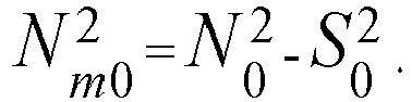
- N m 0 2 N 0 2 ⁇ S 0 2 .
- N mx 1 N x 1 ⁇ S x 1 .
- N mx 2 N x 2 ⁇ S x 2 .
- FIG. 3 shows a process diagram of deducting S 0 1 corresponding to the first energy level (31 keV) and deducting S 0 2 corresponding to the second energy level (81 keV) on the empty tube gamma absorption spectrum of the Ba-133 radioactive source.
- the two deduction lines are artificially set. After the deduction lines are artificially set, a i j , b i j , c i j , and d i j are all constants, and the setting position of the deduction line has a small influence on the metering result to a certain extent, but within an acceptable level.
- the first energy level (31 keV) on the empty tube gamma absorption spectrum is taken as an example.
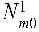
- N 0 1 measured by the probe component 31 actually includes two parts: N m 0 1 and S 0 1 .
- N m 0 1 is a gamma count rate probed by the probe component 31 of the first energy level (31 keV) gamma rays emitted by Ba-133 itself after passing through the empty tube.
- S 0 1 is probed by the probe component 31 after higher energy level rays (such as part of the 81 keV energy level rays) transmitted by Ba-133, which is reduced to 31 keV after Compton scattering, pass through the empty tube, and this part is superimposed on the empty tube gamma absorption spectrum as the first energy level (31 keV) rays transmitted by Ba-133 itself, resulting in distortion of the 31 keV gamma empty tube absorption count rate probed by the probe component 31.
- higher energy level rays such as part of the 81 keV energy level rays
- Ba-133 which is reduced to 31 keV after Compton scattering
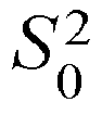
- S 0 2 is deducted corresponding to the second energy level (81 keV) on the empty tube gamma absorption spectrum
- S x 1 is deducted corresponding to the first energy level (31 keV) on the measured gamma absorption spectrum
- a process of deducting S x 2 corresponding to the second energy level (81 keV) on the measured gamma absorption spectrum is consistent with the above situation.
- ⁇ gas 1 is an absorption coefficient of a gas phase relative to a gamma ray of the first energy level, which is a constant.
- ⁇ oil 1 is an absorption coefficient of an oil phase relative to the gamma ray of the first energy level, which is a constant.
- ⁇ water 1 is an absorption coefficient of a water phase relative to the gamma ray of the first energy level, which is a constant.
- ⁇ gas 2 is an absorption coefficient of the gas phase relative to a gamma ray of the gas second energy level, which is a constant.
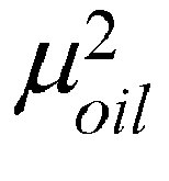
- ⁇ oil 2 is an absorption coefficient of the oil phase relative to the gamma ray of the second energy level, which is a constant.
- ⁇ water 2 is an absorption coefficient of the water phase relative to the gamma ray of the second energy level, which is a constant.
- the metering method of Embodiment 2 is used to deduct and meter the test multi-phase mixed flow to obtain a deducted water content ⁇ water k , and the traditional metering method is used to obtain a distorted water content ⁇ water l , which is compared with a real water content ⁇ water t of the test multi-phase mixed flow.
- a deducted water content metering error W 1 and a distorted water content metering error W 2 are calculated.
- the beneficial effects of the present disclosure are shown in the following two aspects: on one hand, it is reflected in the structure.
- the titanium alloy and the metal beryllium are combined, and are installed and cooperate in a new structural form.
- the titanium alloy which is relatively easy to process and form is used to seal the fluid metering channel
- the titanium alloy and the beryllium pad are combined to bear pressure
- the beryllium pad is used to reduce absorption of gamma rays, so as to solve the problems of inconvenient processing, short service life, and low reliability caused by material (ceramic) problems.
- the beryllium pad is used to reduce absorption of gamma rays, so as to solve the problems of inconvenient processing, short service life, and low reliability caused by material (ceramic) problems.
- the beryllium pad is used to reduce absorption of gamma rays, so as to solve the problems of inconvenient processing, short service life, and low reliability caused by material (ceramic) problems.
Landscapes
- Physics & Mathematics (AREA)
- Fluid Mechanics (AREA)
- General Physics & Mathematics (AREA)
- Electromagnetism (AREA)
- Measurement Of Radiation (AREA)
- Geophysics And Detection Of Objects (AREA)
Description
- The present disclosure relates to equipment and methods for offshore petroleum engineering, and in particular, to underwater multi-phase flow metering equipment for offshore petroleum engineering.
- Chinese patent application (publication number:
CN106706047A ;CN106768120A) submitted by the applicant in 2017 discloses the use of ceramic materials (first and second ceramic sealing gaskets) to seal a fluid metering channel to reduce the absorption of gamma rays, thereby improving the measurement accuracy of the three-phase flow of oil, gas and water. However, there are problems with the production and application of flow metering equipment using ceramic materials to seal a fluid metering channel. Although the ceramic materials have little resistance to the gamma rays, they have poor ductility, are difficult to process into special-shaped structures and easy to break, and cannot meet the requirements of 20-year service life and provide product reliability.CN 206 618 453 U discloses a similar prior art underwater flowmeter for multi-phase flows. - Based on the above reasons, it is particularly urgent to find a replacement solution for ceramic materials. Conventional sealing materials include steel and polyetheretherketone (PEEK). Steel has high density and will absorb too much gamma rays, making it impossible to measure, while the PEEK does not have sufficient strength to be matched with a metal sealing ring. Titanium alloy has high strength, is relatively easy to process and form, and has a density much lower than ordinary steel, making it an alternative. However, when the thickness of the titanium alloy material is excessively large, it will still largely absorb gamma rays, which is unfavorable for improving the measurement accuracy of the three-phase flow of oil, gas and water. The heavy components inside titanium alloy scatter gamma rays largely. Compared with ordinary ceramic windows or PEEK windows, titanium alloy forms an obvious Compton effect on the ray spectrum (see Chinese patent applications with publication numbers:
CN107436165A andCN107331429A ). The high-energy gamma ray γh is partially reduced to the energy level γl after the Compton scattering of the titanium alloy, which may coincide with the low-energy ray γl ' emitted by the gamma source itself, resulting in the distortion of the count rate obtained by the gamma probe, which deepens as the thickness of the titanium alloy penetrated by the gamma rays increases. This requires further adjustment and optimization of the sealing structure in terms of structure and material, reducing the thickness of the titanium alloy while ensuring the compressive strength, and a solution to the influence of Compton scattering on the count rate of the probe is sought. - In view of this, the present disclosure firstly provides a ray transceiving system of an underwater flowmeter, which ensures the compressive strength and reduce the absorption of gamma rays with new material/material combination and structural design.
- The technical solutions are as follows:
A ray transceiving system of an underwater flowmeter includes a flowmeter body. A fluid metering channel extends through the flowmeter body. A transmitting window and a probing window positioned on both sides of the fluid metering channel are arranged on the flowmeter body. An inner end of the transmitting window and an inner end of the probing window are arranged opposite to each other and are respectively in communication with the fluid metering channel separately. A ray transmitting module is arranged in the transmitting window. A ray probing module is arranged in the probing window. The ray transmitting module transmits rays to pass through the fluid metering channel. The ray probing module probes and receives the rays passing through the fluid metering channel. - The ray transmitting module includes a radioactive source assembly, a collimator, and a first isolation seat arranged in sequence. The first isolation seat is located at the inner end of the transmitting window. The first isolation seat separates and seals the fluid metering channel and the transmitting window. An inner end face of the first isolation seat is flush with and adapted to an inner wall of the fluid metering channel.
- The ray probing module includes a probe component, a pressing ring, and a second isolation seat arranged in sequence. The second isolation seat is located at the inner end of the probing window. The second isolation seat separates and seals the fluid metering channel and the probing window. An inner end face of the second isolation seat is flush with and adapted to the inner wall of the fluid metering channel.
- The key lines in:
A first beryllium pad is arranged between the collimator and the first isolation seat, and the first isolation seat is made of titanium alloy. - A second beryllium pad is arranged between the pressing ring and the second isolation seat, and the second isolation seat is made of titanium alloy.
- According to the above technical solution, the titanium alloy and the metal beryllium are combined, and are installed and cooperate in a new structural form. The titanium alloy which is relatively easy to process and form is used to seal the fluid metering channel, the titanium alloy and the beryllium pad are combined to bear pressure, and the beryllium pad is used to reduce absorption of gamma rays, so as to solve the problems of inconvenient processing, short service life, and low reliability caused by material (ceramic) problems.
- In addition, the present disclosure continues to provide a deduction metering method of an underwater flowmeter on the basis of using the titanium alloy as a sealing material, which solves the problem of energy level coincidence caused by Compton scattering from the perspective of improving the accuracy of a gamma count rate, so as to improve the metering accuracy. The technical solutions are as follows:
- A deduction metering method of an underwater flowmeter includes the following steps:
- step I, arranging the above ray transceiving system of an underwater flowmeter, penetrating the fluid metering channel using any two groups of energy levels of the radioactive source assembly, and respectively obtaining gamma count rates N corresponding to a first energy level and a second energy level by the probe component;
- step II, measuring a first empty tube count rate ND and a second empty tube
count rate 
- in a metering state, a three-phase mixed flow of oil, gas and water passes through the fluid metering channel, and a first measured count rate


- step III, delineating a first empty tube
deduction value 
deduction value 


- deducting and correcting the first empty tube
count rate 
count rate 


rate 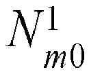
rate 

rate 


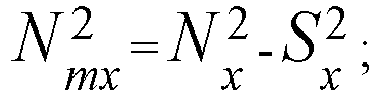
- step IV, calculating a gas phase content αgas, an oil phase content αoil , and a water phase content αwater in the multi-phase mixed flow according to the following formulas:
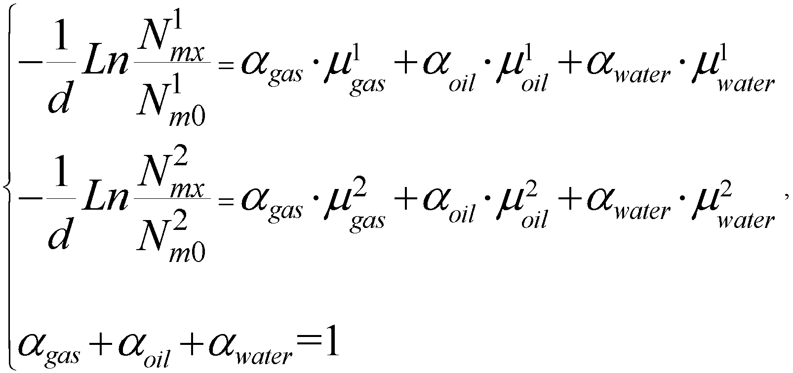
- where
- d is a distance that a gamma ray passes through the fluid metering channel;
-

-
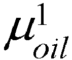
-

-

-

-

- After Compton scattering of the high-energy gamma rays, the scattering low-energy level coincides with the original low-energy level, and the count rate will be superimposed and increased on the gamma absorption spectrum. According to the above method steps, a count rate of the original low-energy level can be obtained by deducting a count rate of the detected scattering low-energy level on the gamma absorption spectrum.
-
-
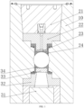
FIG. 1 is a schematic structural diagram of a ray transceiving system of an underwater flowmeter; -
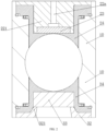
FIG. 2 is a schematic diagram of assembly relationships of acollimator 22, afirst beryllium pad 23, and afirst isolation seat 24, as well as apressing ring 32, asecond beryllium pad 33, and asecond isolation seat 34; and -
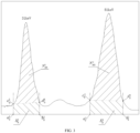
FIG. 3 is a process diagram of deducting

- The following further describes the present disclosure with reference to embodiments and the accompanying drawings.
- As shown in
FIG. 1 andFIG. 2 , a ray transceiving system of an underwater flowmeter includes aflowmeter body 10. A fluid metering channel extends through theflowmeter body 10. The fluid metering channel is conventionally arranged as a circular hole type channel. A transmitting window and a probing window positioned on both sides of the fluid metering channel are arranged on theflowmeter body 10. An inner end of the transmitting window and an inner end of the probing window are arranged opposite to each other and are respectively in communication with the fluid metering channel separately. A ray transmitting module is arranged in the transmitting window. A ray probing module is arranged in the probing window. The ray transmitting module transmits rays to pass perpendicular to a hole center line of the fluid metering channel. The ray probing module probes and receives the rays passing through the fluid metering channel. - The ray transmitting module includes a
radioactive source assembly 21, acollimator 22, and afirst isolation seat 24 arranged in sequence. Thefirst isolation seat 24 is located at the inner end of the transmitting window. Thefirst isolation seat 24 separates and seals the fluid metering channel and the transmitting window. An inner end face of thefirst isolation seat 24 is flush with and adapted to an inner wall of the fluid metering channel. - The ray probing module includes a
probe component 31, apressing ring 32, and asecond isolation seat 34 arranged in sequence. Thesecond isolation seat 34 is located at the inner end of the probing window. Thesecond isolation seat 34 separates and seals the fluid metering channel and the probing window. An inner end face of thesecond isolation seat 34 is flush with and adapted to the inner wall of the fluid metering channel. - A
first beryllium pad 23 is arranged between thecollimator 22 and thefirst isolation seat 24, and thefirst isolation seat 24 is made of titanium alloy. - A
second beryllium pad 33 is arranged between thepressing ring 32 and thesecond isolation seat 34, and thesecond isolation seat 34 is made of titanium alloy. - A surface of the
first isolation seat 24 facing thecollimator 22 is provided with a first embedded counterbore. Thecollimator 22 is provided with a firsttop piece 221 matched with the first embedded counterbore. The firsttop piece 221 is provided with a beryllium sheet insertion opening. The beryllium sheet insertion opening faces a bottom of the first embedded counterbore. Thefirst beryllium pad 23 is embedded in and matched with the beryllium sheet insertion opening. The firsttop piece 221 is embedded in the first embedded counterbore. A protruding end of the firsttop piece 221 abuts against the bottom of the first embedded counterbore. Thefirst beryllium pad 23 abuts against the bottom of the first embedded counterbore. Acollimating hole 22a penetrates through thecollimator 22. A hole center line of thecollimating hole 22a is perpendicular to and intersects with the hole center line of the fluid metering channel. Thecollimating hole 22a includes two sections, one of which has a smaller hole diameter than the other. The small hole end of thecollimating hole 22a faces theradioactive source assembly 21. The large hole end of thecollimating hole 22a is in communication with the beryllium sheet insertion opening and faces thefirst beryllium pad 23. - A surface of the
second isolation seat 34 facing thepressing ring 32 is provided with a second embedded counterbore. Thesecond beryllium pad 33 is embedded in and matched with the second embedded counterbore. Thepressing ring 32 abuts both thesecond beryllium pad 33 and thesecond isolation seat 34. The second embedded counterbore includes a circular bore segment and a circular frustum bore segment. The circular bore segment is adjacent to the fluid metering channel. The circular frustum bore segment faces thepressing ring 32. Thesecond beryllium pad 33 is embedded in the circular bore segment. An end face of thepressing ring 32 facing the second embedded counterbore is provided with a ring ofpressing flange 321. Thepressing flange 321 is arranged adjacent to an inner ring of thepressing ring 32. An inner ring of thepressing flange 321 is flush with the inner ring of thepressing ring 32. Thepressing flange 321 is embedded in the circular frustum bore segment. An outer ring of thepressing flange 321 is adapted to and matched with a bore wall of the circular frustum bore segment. Thepressing ring 32 and thepressing flange 321 are integrally formed. An arc-shaped transition is formed between an outer wall and two end faces of the outer ring of thepressing flange 321. An arc-shaped transition is formed between a large opening section and an end face are of the circular frustum bore segment to avoid stress concentration during pressure bearing and damage to thepressing ring 32 and thesecond isolation seat 34. An embedded end face of thepressing flange 321 abuts thesecond beryllium pad 33. Thepressing ring 32 and the outer ring of thepressing flange 321 abut thesecond isolation seat 34. A thickness of thesecond beryllium pad 33 is greater than a thickness of thefirst beryllium pad 23. - A deduction metering method of an underwater flowmeter includes the following steps.
- Step I, the ray transceiving system of an underwater flowmeter according to Embodiment 1 is arranged. The fluid metering channel is penetrated using any two groups of energy levels of the
radioactive source assembly 21. Gamma count rates N corresponding to a first energy level and a second energy level are respectively obtained by theprobe component 31. - The
radioactive source assembly 21 can use a Ba-133 radioactive source assembly. The Ba-133 radioactive source mainly has three energy levels that can be used for flow measurement, namely 31 keV, 81 keV, and 356 keV respectively. As a specific embodiment, the multi-phase flow is measured by using two energy levels of 31 keV and 81 keV of Ba-133. - Step II, a first empty tube
count rate 
count rate 
probe component 31 under a condition of emptying the fluid metering channel. - In a metering state, a three-phase mixed flow of oil, gas and water passes through the fluid metering channel, and a first measured count rate


probe component 31 respectively. - Step III, a first empty tube
deduction value 
deduction value 


- Specifically, the first empty tube
deduction value 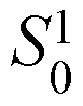
deduction value 


- Deduction ranges are delineated corresponding to the first energy level and the second energy level on the empty tube gamma absorption spectrum and the measured gamma absorption spectrum respectively. The deduction range includes two deduction lines perpendicular to an abscissa axis of the gamma absorption spectra. The two deduction lines are on both sides of peak values of the corresponding energy levels. Intersection points of the two deduction lines and the abscissa axis of the corresponding gamma absorption spectra are


- The first empty tube
deduction value 


- The second empty tube
deduction value 


- The first measured deduction value Sx is a trapezoidal or rectangular area enclosed by four points


- The second measured deduction value


- The first empty tube
count rate 
count rate 

rate 
rate 

rate 



-
FIG. 3 shows a process diagram of deducting


probe component 31 actually includes two parts:

probe component 31 of the first energy level (31 keV) gamma rays emitted by Ba-133 itself after passing through the empty tube.
probe component 31 after higher energy level rays (such as part of the 81 keV energy level rays) transmitted by Ba-133, which is reduced to 31 keV after Compton scattering, pass through the empty tube, and this part is superimposed on the empty tube gamma absorption spectrum as the first energy level (31 keV) rays transmitted by Ba-133 itself, resulting in distortion of the 31 keV gamma empty tube absorption count rate probed by theprobe component 31. - Similarly:


- Step IV, a gas phase content αgas , an oil phase content αoil , and a water phase content αwater in the multi-phase mixed flow are calculated according to the following formulas:

where:
d is a distance that a gamma ray passes through the fluid metering channel, namely, a diameter of the fluid metering channel.



- The metering method of
Embodiment 2 is used to deduct and meter the test multi-phase mixed flow to obtain a deducted water content


Embodiment 2 is: the traditional metering method does not include step III, and the following formulas are used to calculate the distorted water content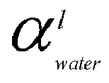


- The water content metering error W 1 and the distorted water content metering error W2 are calculated according to the formulas:


- Data such as the real water content of the 5 groups of test multi-phase mixed flows randomly selected for comparison in the test process is shown in Table 1:
Table 1. Data table of real water content of test multi-phase mixed flow Liquid volume Gas volume 

Temperature Pressure Unit m3/d Sm3/d % % Deg.C kPa Group 1 845.74 0.00 80.10 0.00 23.71 128.87 Group 2868.12 0.00 74.79 0.00 23.80 127.87 Group 3 852.34 522.27 75.00 31.98 24.11 133.87 Group 4 1696.84 0.00 100.00 0.00 22.02 158.87 Group 5 1152.62 927.69 29.88 34.00 22.91 159.87 - The calculated deducted water content


Table 2. Water content and water content metering error of test multi-phase mixed flow 


W 2 W1 Unit % m3/d Sm3/d % % Group 1 80.10 75.20 79.80 -4.90 -0.30 Group 274.79 69.40 76.20 -5.39 1.41 Group 3 75.00 67.40 73.50 -7.60 -1.50 Group 4 100.00 96.30 99.80 -3.70 -0.20 Group 5 29.88 18.40 31.80 -11.48 1.92 - It can be seen from Table 2 that using the deduction algorithm of
Embodiment 2, the deducted water content

- The beneficial effects of the present disclosure are shown in the following two aspects: on one hand, it is reflected in the structure. The titanium alloy and the metal beryllium are combined, and are installed and cooperate in a new structural form. The titanium alloy which is relatively easy to process and form is used to seal the fluid metering channel, the titanium alloy and the beryllium pad are combined to bear pressure, and the beryllium pad is used to reduce absorption of gamma rays, so as to solve the problems of inconvenient processing, short service life, and low reliability caused by material (ceramic) problems. On the other hand, it is reflected in the metering method. By deducting the count rate of the scattering low-energy levels detected on the gamma absorption spectrum, it can be metered with the result closer to the real count rate, so as to avoid the great impact of the Compton scattering effect on the results of gamma ray measurement of multi-phase flow and improve the metering accuracy.
- Finally, it should be noted that the above description is only a preferred embodiment of the present disclosure. Under the enlightenment of the present disclosure, those of ordinary skill in the art can make a variety of similar representations without departing from the purpose of the present disclosure and the claims, and such transformations all fall within the protection scope of the present disclosure.
Claims (7)
- A ray transceiving system of an underwater flowmeter, comprising a flowmeter body (10), wherein a fluid metering channel extends through the flowmeter body (10), a transmitting window and a probing window positioned on both sides of the fluid metering channel are arranged on the flowmeter body (10), an inner end of the transmitting window and an inner end of the probing window are arranged opposite to each other and are respectively in communication with the fluid metering channel, a ray transmitting module is arranged in the transmitting window, a ray probing module is arranged in the probing window, the ray transmitting module transmits rays to pass through the fluid metering channel, and the ray probing module probes and receives the rays passing through the fluid metering channel;the ray transmitting module comprises a radioactive source assembly (21), a collimator (22), and a first isolation seat (24) arranged in sequence, wherein the first isolation seat (24) is located at the inner end of the transmitting window, the first isolation seat (24) separates and seals the fluid metering channel and the transmitting window, and an inner end face of the first isolation seat (24) is flush with and adapted to an inner wall of the fluid metering channel; andthe ray probing module comprises a probe component (31), a pressing ring (32), and a second isolation seat (34) arranged in sequence, wherein the second isolation seat (34) is located at the inner end of the probing window, the second isolation seat (34) separates and seals the fluid metering channel and the probing window, and an inner end face of the second isolation seat (34) is flush with and adapted to the inner wall of the fluid metering channel;characterized in thata first beryllium pad (23) is arranged between the collimator (22) and the first isolation seat (24), and the first isolation seat (24) is made of titanium alloy; anda second beryllium pad (33) is arranged between the pressing ring (32) and the second isolation seat (34), and the second isolation seat (34) is made of titanium alloy.
- The ray transceiving system of the underwater flowmeter according to claim 1, characterized in that a surface of the first isolation seat (24) facing the collimator (22) is provided with a first embedded counterbore, the collimator (22) is provided with a first top piece (221) matched with the first embedded counterbore, the first top piece (221) is provided with a beryllium sheet insertion opening, the beryllium sheet insertion opening faces a bottom of the first embedded counterbore, the first beryllium pad (23) is embedded in and matched with the beryllium sheet insertion opening, the first top piece (221) is embedded in the first embedded counterbore, a protruding end of the first top piece (221) abuts against the bottom of the first embedded counterbore, the first beryllium pad (23) abuts against the bottom of the first embedded counterbore, a collimating hole (22a) penetrates through the collimator (22), the collimating hole (22a) comprises one end with a large hole diameter and the other end with a small hole diameter, the small hole end of the collimating hole (22a) faces the radioactive source assembly (21), and the large hole end of the collimating hole (22a) is in communication with the beryllium sheet insertion opening and faces the first beryllium pad (23).
- The ray transceiving system of the underwater flowmeter according to claim 1 or 2, characterized in that a surface of the second isolation seat (34) facing the pressing ring (32) is provided with a second embedded counterbore, the second beryllium pad (33) is embedded in and matched with the second embedded counterbore, and the pressing ring (32) abuts both the second beryllium pad (33) and the second isolation seat (34).
- The ray transceiving system of the underwater flowmeter according to claim 3, characterized in that the second embedded counterbore comprises a circular bore segment and a circular frustum bore segment, wherein the circular bore segment is adjacent to the fluid metering channel, the circular frustum bore segment faces the pressing ring (32), the second beryllium pad (33) is embedded in the circular bore segment, an end face of the pressing ring (32) facing the second embedded counterbore is provided with a ring of pressing flange (321), the pressing flange (321) is arranged adjacent to an inner ring of the pressing ring (32), an inner ring of the pressing flange (321) is flush with the inner ring of the pressing ring (32), the pressing flange (321) is embedded in the circular frustum bore segment, an outer ring of the pressing flange (321) is adapted to and matched with a bore wall of the circular frustum bore segment, an embedded end face of the pressing flange (321) abuts the second beryllium pad (33), and the pressing ring (32) and the outer ring of the pressing flange (321) abut the second isolation seat (34).
- The ray transceiving system of the underwater flowmeter according to claim 1 or 2, characterized in that a thickness of the second beryllium pad (33) is greater than a thickness of the first beryllium pad (23).
- A deduction metering method of an underwater flowmeter, characterized by comprising the following steps:step I, arranging the ray transceiving system of the underwater flowmeter according to any one of claims 1 to 5, penetrating the fluid metering channel using any two groups of energy levels of the radioactive source assembly (21), and respectively obtaining gamma count rates N corresponding to a first energy level and a second energy level by the probe component (31);step II, measuring a first empty tube count rate

 in a metering state, a three-phase mixed flow of oil, gas and water passes through the fluid metering channel, and a first measured count rate
 step III, delineating a first empty tube deduction value


 deducting and correcting the first empty tube count rate


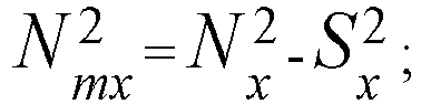 step IV, calculating a gas phase content αgas , an oil phase content αoil, and a water phase content αwαter in the multi-phase mixed flow according to the following formulas:
 whereind is a distance that a gamma ray passes through the fluid metering channel;


- The deduction metering method of the underwater flowmeter according to claim 6, characterized in that in step III, the first empty tube deduction value


 delineating deduction ranges corresponding to the first energy level and the second energy level on the empty tube gamma absorption spectrum and the measured gamma absorption spectrum respectively, wherein the deduction range comprises two deduction lines perpendicular to an abscissa axis of the gamma absorption spectra, the two deduction lines are located on both sides of peak values of the corresponding energy levels, intersection points of the two deduction lines and the abscissa axis of the corresponding gamma absorption spectra are


 the first empty tube deduction value

 the second empty tube deduction value

 the first measured deduction value

 the second measured deduction value


Applications Claiming Priority (1)
| Application Number | Priority Date | Filing Date | Title |
|---|---|---|---|
| CN202111267607.2A CN113701837B (en) | 2021-10-29 | 2021-10-29 | Underwater flowmeter ray transceiver system and deduction measurement method |
Publications (2)
| Publication Number | Publication Date |
|---|---|
| EP4174453A1 EP4174453A1 (en) | 2023-05-03 |
| EP4174453B1 true EP4174453B1 (en) | 2023-11-29 |
Family
ID=78647455
Family Applications (1)
| Application Number | Title | Priority Date | Filing Date |
|---|---|---|---|
| EP22187955.4A Active EP4174453B1 (en) | 2021-10-29 | 2022-07-29 | Ray transceiving system of underwater flowmeter and deduction metering method |
Country Status (3)
| Country | Link |
|---|---|
| US (1) | US12442674B2 (en) |
| EP (1) | EP4174453B1 (en) |
| CN (1) | CN113701837B (en) |
Families Citing this family (1)
| Publication number | Priority date | Publication date | Assignee | Title |
|---|---|---|---|---|
| CN114046830B (en) * | 2021-11-10 | 2024-03-08 | 海默科技(集团)股份有限公司 | Flow meter metering parameter detection system |
Citations (1)
| Publication number | Priority date | Publication date | Assignee | Title |
|---|---|---|---|---|
| US20170010225A1 (en) * | 2009-12-01 | 2017-01-12 | Schlumberger Technology Corporation | Pre-stressed gamma densitometer window and method of fabrication |
Family Cites Families (13)
| Publication number | Priority date | Publication date | Assignee | Title |
|---|---|---|---|---|
| FR2939896B1 (en) * | 2008-12-12 | 2011-05-06 | Geoservices Equipements | DEVICE FOR TRANSMITTING A FIRST BEAM OF HIGH ENERGY GAMMA PHOTONS AND A SECOND BEAM OF LOW ENERGY GAMMA PHOTONS, MEASUREMENT ASSEMBLY AND METHOD THEREOF |
| RU2533758C2 (en) * | 2009-07-07 | 2014-11-20 | Сименс Акциенгезелльшафт | Device and method for measurement of multiphase fluid flow |
| US20120087467A1 (en) * | 2010-10-12 | 2012-04-12 | Roxar Flow Measurement As | X-ray based densitometer for multiphase flow measurement |
| CN104359516A (en) * | 2014-11-07 | 2015-02-18 | 宁波美卓伦仪表有限公司 | Fully titanium alloy packaging ultrasonic-wave dual-use gas-liquid flow sensor |
| US9870609B2 (en) * | 2016-06-03 | 2018-01-16 | Conduent Business Services, Llc | System and method for assessing usability of captured images |
| CN206618453U (en) * | 2017-01-10 | 2017-11-07 | 海默科技(集团)股份有限公司 | Multi-phase flowmeter phase fraction detecting system under water |
| CN106768120B (en) * | 2017-01-10 | 2023-04-28 | 海默科技(集团)股份有限公司 | Phase fraction detection system of underwater multiphase flowmeter |
| CN106706047B (en) | 2017-01-10 | 2023-05-09 | 海默科技(集团)股份有限公司 | Underwater multiphase flowmeter based on Ba133 |
| CN107436165B (en) * | 2017-08-10 | 2019-08-20 | 海默科技(集团)股份有限公司 | Method for Determination of Phase Fraction of Multiphase Flow by Single Source Radiation |
| CN107331429B (en) | 2017-08-10 | 2023-05-23 | 海默科技(集团)股份有限公司 | Multiphase flow phase fraction measuring device single-source dual-energy gamma and X-ray source bin |
| CN109443466B (en) * | 2018-12-29 | 2024-11-15 | 无锡洋湃科技有限公司 | Device and method for measuring the mass flow of gas, liquid and solid in multiphase flow with full cross section |
| CN109655930B (en) * | 2019-01-15 | 2023-09-22 | 中国海洋石油集团有限公司 | Gamma ray detection system and signal calibration and mixed medium phase fraction calculation method |
| US12247480B2 (en) * | 2020-07-23 | 2025-03-11 | Schlumberger Technology Corporation | Lower-density or collimating well-logging radiation detector windows |
-
2021
- 2021-10-29 CN CN202111267607.2A patent/CN113701837B/en active Active
-
2022
- 2022-07-29 EP EP22187955.4A patent/EP4174453B1/en active Active
- 2022-08-22 US US17/893,023 patent/US12442674B2/en active Active
Patent Citations (1)
| Publication number | Priority date | Publication date | Assignee | Title |
|---|---|---|---|---|
| US20170010225A1 (en) * | 2009-12-01 | 2017-01-12 | Schlumberger Technology Corporation | Pre-stressed gamma densitometer window and method of fabrication |
Also Published As
| Publication number | Publication date |
|---|---|
| CN113701837B (en) | 2022-03-04 |
| CN113701837A (en) | 2021-11-26 |
| US20230146177A1 (en) | 2023-05-11 |
| EP4174453A1 (en) | 2023-05-03 |
| US12442674B2 (en) | 2025-10-14 |
Similar Documents
| Publication | Publication Date | Title |
|---|---|---|
| US6335959B1 (en) | Apparatus and method for determining oil well effluent characteristics for inhomogeneous flow conditions | |
| EP2275804B1 (en) | A method and system for determining the constituent content of a multiphase fluid | |
| Andreopoulos et al. | The response of a turbulent boundary layer to a short length of surface roughness | |
| US4441362A (en) | Method for determining volumetric fractions and flow rates of individual phases within a multi-phase flow regime | |
| CN105890689B (en) | Measuring device and measuring method for measuring gas-oil-water three-phase mass flow in moisture | |
| US7676344B2 (en) | Apparatus and method for determining a characteristic ratio and a parameter affecting the characterisitic ratio of a multiphase fluid mixture | |
| EP4174453A1 (en) | Ray transceiving system of underwater flowmeter and deduction metering method | |
| GB2325736A (en) | Characterising oil well effluents by attentuation of gamma rays of two energy levels | |
| US8939033B2 (en) | Flow meter system and method for measuring an amount of liquid in a largely gaseous multiphase flow | |
| AU679064B2 (en) | Fluid composition meter | |
| US10914622B2 (en) | Apparatus and method for measuring mass flow-rates of gas, oil and water phases in wet gas | |
| EP1970702A1 (en) | Detection of an element in a flow | |
| CN103399025A (en) | Method and apparatus used for on-line detection of sand mass fraction of multiphase flow | |
| Marion et al. | Investigation of the Be 9 (p, n) B 9 and Be 9 (p, α γ) Li 6 Reactions | |
| US12241771B2 (en) | Energy correlation flow meters | |
| Chan et al. | Measurement of mass flux in high temperature high pressure steam–water two-phase flow using a combination of pitot tubes and a gamma densitometer | |
| US20260002893A1 (en) | Systems and methods for measurement of fluid composition | |
| Park et al. | Design and application of a single-beam gamma densitometer for void fraction measurement in a small diameter stainless steel pipe in a critical flow condition | |
| Bom et al. | Accuracy aspects in multiphase flow metering using X-ray transmission | |
| Lawson et al. | Neutron depth dose measurements in a tissue-equivalent phantom for an incident Pu-Be spectrum | |
| Weddell | Scattering of 4.4-Mev Neutrons by Aluminum, Calcium, Chromium, and Bismuth | |
| Gunnink et al. | Evaluation of TASTEX Task H: measurement of plutonium isotopic abundances by gamma-ray spectrometry | |
| Fedorov et al. | Metrology and standardization in pressureless flows | |
| CN116008320B (en) | Meng Ka simulation and function model-based waste bin SGS efficiency calibration method | |
| McLeod et al. | Radiotracers in gas-liquid transportation problems-a field case |
Legal Events
| Date | Code | Title | Description |
|---|---|---|---|
| PUAI | Public reference made under article 153(3) epc to a published international application that has entered the european phase |
Free format text: ORIGINAL CODE: 0009012 |
|
| STAA | Information on the status of an ep patent application or granted ep patent |
Free format text: STATUS: REQUEST FOR EXAMINATION WAS MADE |
|
| 17P | Request for examination filed |
Effective date: 20220729 |
|
| AK | Designated contracting states |
Kind code of ref document: A1 Designated state(s): AL AT BE BG CH CY CZ DE DK EE ES FI FR GB GR HR HU IE IS IT LI LT LU LV MC MK MT NL NO PL PT RO RS SE SI SK SM TR |
|
| GRAP | Despatch of communication of intention to grant a patent |
Free format text: ORIGINAL CODE: EPIDOSNIGR1 |
|
| STAA | Information on the status of an ep patent application or granted ep patent |
Free format text: STATUS: GRANT OF PATENT IS INTENDED |
|
| RIC1 | Information provided on ipc code assigned before grant |
Ipc: G01N 23/12 20180101ALN20230630BHEP Ipc: G01F 1/74 20060101ALN20230630BHEP Ipc: G01V 5/08 20060101ALI20230630BHEP Ipc: G01F 1/66 20220101AFI20230630BHEP |
|
| INTG | Intention to grant announced |
Effective date: 20230724 |
|
| GRAS | Grant fee paid |
Free format text: ORIGINAL CODE: EPIDOSNIGR3 |
|
| GRAA | (expected) grant |
Free format text: ORIGINAL CODE: 0009210 |
|
| STAA | Information on the status of an ep patent application or granted ep patent |
Free format text: STATUS: THE PATENT HAS BEEN GRANTED |
|
| AK | Designated contracting states |
Kind code of ref document: B1 Designated state(s): AL AT BE BG CH CY CZ DE DK EE ES FI FR GB GR HR HU IE IS IT LI LT LU LV MC MK MT NL NO PL PT RO RS SE SI SK SM TR |
|
| REG | Reference to a national code |
Ref country code: GB Ref legal event code: FG4D |
|
| REG | Reference to a national code |
Ref country code: CH Ref legal event code: EP |
|
| REG | Reference to a national code |
Ref country code: DE Ref legal event code: R096 Ref document number: 602022001161 Country of ref document: DE |
|
| REG | Reference to a national code |
Ref country code: IE Ref legal event code: FG4D |
|
| REG | Reference to a national code |
Ref country code: LT Ref legal event code: MG9D |
|
| REG | Reference to a national code |
Ref country code: NL Ref legal event code: MP Effective date: 20231129 |
|
| PG25 | Lapsed in a contracting state [announced via postgrant information from national office to epo] |
Ref country code: GR Free format text: LAPSE BECAUSE OF FAILURE TO SUBMIT A TRANSLATION OF THE DESCRIPTION OR TO PAY THE FEE WITHIN THE PRESCRIBED TIME-LIMIT Effective date: 20240301 |
|
| PG25 | Lapsed in a contracting state [announced via postgrant information from national office to epo] |
Ref country code: IS Free format text: LAPSE BECAUSE OF FAILURE TO SUBMIT A TRANSLATION OF THE DESCRIPTION OR TO PAY THE FEE WITHIN THE PRESCRIBED TIME-LIMIT Effective date: 20240329 |
|
| PG25 | Lapsed in a contracting state [announced via postgrant information from national office to epo] |
Ref country code: LT Free format text: LAPSE BECAUSE OF FAILURE TO SUBMIT A TRANSLATION OF THE DESCRIPTION OR TO PAY THE FEE WITHIN THE PRESCRIBED TIME-LIMIT Effective date: 20231129 |
|
| PG25 | Lapsed in a contracting state [announced via postgrant information from national office to epo] |
Ref country code: ES Free format text: LAPSE BECAUSE OF FAILURE TO SUBMIT A TRANSLATION OF THE DESCRIPTION OR TO PAY THE FEE WITHIN THE PRESCRIBED TIME-LIMIT Effective date: 20231129 |
|
| PG25 | Lapsed in a contracting state [announced via postgrant information from national office to epo] |
Ref country code: LT Free format text: LAPSE BECAUSE OF FAILURE TO SUBMIT A TRANSLATION OF THE DESCRIPTION OR TO PAY THE FEE WITHIN THE PRESCRIBED TIME-LIMIT Effective date: 20231129 Ref country code: IS Free format text: LAPSE BECAUSE OF FAILURE TO SUBMIT A TRANSLATION OF THE DESCRIPTION OR TO PAY THE FEE WITHIN THE PRESCRIBED TIME-LIMIT Effective date: 20240329 Ref country code: GR Free format text: LAPSE BECAUSE OF FAILURE TO SUBMIT A TRANSLATION OF THE DESCRIPTION OR TO PAY THE FEE WITHIN THE PRESCRIBED TIME-LIMIT Effective date: 20240301 Ref country code: ES Free format text: LAPSE BECAUSE OF FAILURE TO SUBMIT A TRANSLATION OF THE DESCRIPTION OR TO PAY THE FEE WITHIN THE PRESCRIBED TIME-LIMIT Effective date: 20231129 Ref country code: BG Free format text: LAPSE BECAUSE OF FAILURE TO SUBMIT A TRANSLATION OF THE DESCRIPTION OR TO PAY THE FEE WITHIN THE PRESCRIBED TIME-LIMIT Effective date: 20240229 |
|
| REG | Reference to a national code |
Ref country code: AT Ref legal event code: MK05 Ref document number: 1636556 Country of ref document: AT Kind code of ref document: T Effective date: 20231129 |
|
| PG25 | Lapsed in a contracting state [announced via postgrant information from national office to epo] |
Ref country code: NL Free format text: LAPSE BECAUSE OF FAILURE TO SUBMIT A TRANSLATION OF THE DESCRIPTION OR TO PAY THE FEE WITHIN THE PRESCRIBED TIME-LIMIT Effective date: 20231129 |
|
| PG25 | Lapsed in a contracting state [announced via postgrant information from national office to epo] |
Ref country code: SE Free format text: LAPSE BECAUSE OF FAILURE TO SUBMIT A TRANSLATION OF THE DESCRIPTION OR TO PAY THE FEE WITHIN THE PRESCRIBED TIME-LIMIT Effective date: 20231129 Ref country code: RS Free format text: LAPSE BECAUSE OF FAILURE TO SUBMIT A TRANSLATION OF THE DESCRIPTION OR TO PAY THE FEE WITHIN THE PRESCRIBED TIME-LIMIT Effective date: 20231129 Ref country code: PL Free format text: LAPSE BECAUSE OF FAILURE TO SUBMIT A TRANSLATION OF THE DESCRIPTION OR TO PAY THE FEE WITHIN THE PRESCRIBED TIME-LIMIT Effective date: 20231129 Ref country code: NO Free format text: LAPSE BECAUSE OF FAILURE TO SUBMIT A TRANSLATION OF THE DESCRIPTION OR TO PAY THE FEE WITHIN THE PRESCRIBED TIME-LIMIT Effective date: 20240229 Ref country code: NL Free format text: LAPSE BECAUSE OF FAILURE TO SUBMIT A TRANSLATION OF THE DESCRIPTION OR TO PAY THE FEE WITHIN THE PRESCRIBED TIME-LIMIT Effective date: 20231129 Ref country code: LV Free format text: LAPSE BECAUSE OF FAILURE TO SUBMIT A TRANSLATION OF THE DESCRIPTION OR TO PAY THE FEE WITHIN THE PRESCRIBED TIME-LIMIT Effective date: 20231129 Ref country code: HR Free format text: LAPSE BECAUSE OF FAILURE TO SUBMIT A TRANSLATION OF THE DESCRIPTION OR TO PAY THE FEE WITHIN THE PRESCRIBED TIME-LIMIT Effective date: 20231129 |
|
| PG25 | Lapsed in a contracting state [announced via postgrant information from national office to epo] |
Ref country code: DK Free format text: LAPSE BECAUSE OF FAILURE TO SUBMIT A TRANSLATION OF THE DESCRIPTION OR TO PAY THE FEE WITHIN THE PRESCRIBED TIME-LIMIT Effective date: 20231129 |
|
| PG25 | Lapsed in a contracting state [announced via postgrant information from national office to epo] |
Ref country code: CZ Free format text: LAPSE BECAUSE OF FAILURE TO SUBMIT A TRANSLATION OF THE DESCRIPTION OR TO PAY THE FEE WITHIN THE PRESCRIBED TIME-LIMIT Effective date: 20231129 Ref country code: AT Free format text: LAPSE BECAUSE OF FAILURE TO SUBMIT A TRANSLATION OF THE DESCRIPTION OR TO PAY THE FEE WITHIN THE PRESCRIBED TIME-LIMIT Effective date: 20231129 |
|
| PG25 | Lapsed in a contracting state [announced via postgrant information from national office to epo] |
Ref country code: SK Free format text: LAPSE BECAUSE OF FAILURE TO SUBMIT A TRANSLATION OF THE DESCRIPTION OR TO PAY THE FEE WITHIN THE PRESCRIBED TIME-LIMIT Effective date: 20231129 |
|
| PG25 | Lapsed in a contracting state [announced via postgrant information from national office to epo] |
Ref country code: SM Free format text: LAPSE BECAUSE OF FAILURE TO SUBMIT A TRANSLATION OF THE DESCRIPTION OR TO PAY THE FEE WITHIN THE PRESCRIBED TIME-LIMIT Effective date: 20231129 Ref country code: SK Free format text: LAPSE BECAUSE OF FAILURE TO SUBMIT A TRANSLATION OF THE DESCRIPTION OR TO PAY THE FEE WITHIN THE PRESCRIBED TIME-LIMIT Effective date: 20231129 Ref country code: RO Free format text: LAPSE BECAUSE OF FAILURE TO SUBMIT A TRANSLATION OF THE DESCRIPTION OR TO PAY THE FEE WITHIN THE PRESCRIBED TIME-LIMIT Effective date: 20231129 Ref country code: IT Free format text: LAPSE BECAUSE OF FAILURE TO SUBMIT A TRANSLATION OF THE DESCRIPTION OR TO PAY THE FEE WITHIN THE PRESCRIBED TIME-LIMIT Effective date: 20231129 Ref country code: EE Free format text: LAPSE BECAUSE OF FAILURE TO SUBMIT A TRANSLATION OF THE DESCRIPTION OR TO PAY THE FEE WITHIN THE PRESCRIBED TIME-LIMIT Effective date: 20231129 Ref country code: DK Free format text: LAPSE BECAUSE OF FAILURE TO SUBMIT A TRANSLATION OF THE DESCRIPTION OR TO PAY THE FEE WITHIN THE PRESCRIBED TIME-LIMIT Effective date: 20231129 Ref country code: CZ Free format text: LAPSE BECAUSE OF FAILURE TO SUBMIT A TRANSLATION OF THE DESCRIPTION OR TO PAY THE FEE WITHIN THE PRESCRIBED TIME-LIMIT Effective date: 20231129 Ref country code: AT Free format text: LAPSE BECAUSE OF FAILURE TO SUBMIT A TRANSLATION OF THE DESCRIPTION OR TO PAY THE FEE WITHIN THE PRESCRIBED TIME-LIMIT Effective date: 20231129 |
|
| PG25 | Lapsed in a contracting state [announced via postgrant information from national office to epo] |
Ref country code: PT Free format text: LAPSE BECAUSE OF FAILURE TO SUBMIT A TRANSLATION OF THE DESCRIPTION OR TO PAY THE FEE WITHIN THE PRESCRIBED TIME-LIMIT Effective date: 20240401 |
|
| PG25 | Lapsed in a contracting state [announced via postgrant information from national office to epo] |
Ref country code: PT Free format text: LAPSE BECAUSE OF FAILURE TO SUBMIT A TRANSLATION OF THE DESCRIPTION OR TO PAY THE FEE WITHIN THE PRESCRIBED TIME-LIMIT Effective date: 20240401 |
|
| REG | Reference to a national code |
Ref country code: DE Ref legal event code: R097 Ref document number: 602022001161 Country of ref document: DE |
|
| PLBE | No opposition filed within time limit |
Free format text: ORIGINAL CODE: 0009261 |
|
| STAA | Information on the status of an ep patent application or granted ep patent |
Free format text: STATUS: NO OPPOSITION FILED WITHIN TIME LIMIT |
|
| PG25 | Lapsed in a contracting state [announced via postgrant information from national office to epo] |
Ref country code: SI Free format text: LAPSE BECAUSE OF FAILURE TO SUBMIT A TRANSLATION OF THE DESCRIPTION OR TO PAY THE FEE WITHIN THE PRESCRIBED TIME-LIMIT Effective date: 20231129 |
|
| PG25 | Lapsed in a contracting state [announced via postgrant information from national office to epo] |
Ref country code: SI Free format text: LAPSE BECAUSE OF FAILURE TO SUBMIT A TRANSLATION OF THE DESCRIPTION OR TO PAY THE FEE WITHIN THE PRESCRIBED TIME-LIMIT Effective date: 20231129 |
|
| 26N | No opposition filed |
Effective date: 20240830 |
|
| REG | Reference to a national code |
Ref country code: DE Ref legal event code: R119 Ref document number: 602022001161 Country of ref document: DE |
|
| PG25 | Lapsed in a contracting state [announced via postgrant information from national office to epo] |
Ref country code: MC Free format text: LAPSE BECAUSE OF FAILURE TO SUBMIT A TRANSLATION OF THE DESCRIPTION OR TO PAY THE FEE WITHIN THE PRESCRIBED TIME-LIMIT Effective date: 20231129 |
|
| PG25 | Lapsed in a contracting state [announced via postgrant information from national office to epo] |
Ref country code: LU Free format text: LAPSE BECAUSE OF NON-PAYMENT OF DUE FEES Effective date: 20240729 |
|
| PG25 | Lapsed in a contracting state [announced via postgrant information from national office to epo] |
Ref country code: LU Free format text: LAPSE BECAUSE OF NON-PAYMENT OF DUE FEES Effective date: 20240729 |
|
| PG25 | Lapsed in a contracting state [announced via postgrant information from national office to epo] |
Ref country code: DE Free format text: LAPSE BECAUSE OF NON-PAYMENT OF DUE FEES Effective date: 20250201 |
|
| PG25 | Lapsed in a contracting state [announced via postgrant information from national office to epo] |
Ref country code: BE Free format text: LAPSE BECAUSE OF NON-PAYMENT OF DUE FEES Effective date: 20240731 |
|
| PG25 | Lapsed in a contracting state [announced via postgrant information from national office to epo] |
Ref country code: FR Free format text: LAPSE BECAUSE OF NON-PAYMENT OF DUE FEES Effective date: 20240731 |
|
| REG | Reference to a national code |
Ref country code: BE Ref legal event code: MM Effective date: 20240731 |
|
| PG25 | Lapsed in a contracting state [announced via postgrant information from national office to epo] |
Ref country code: IE Free format text: LAPSE BECAUSE OF NON-PAYMENT OF DUE FEES Effective date: 20240729 |
|
| PG25 | Lapsed in a contracting state [announced via postgrant information from national office to epo] |
Ref country code: FI Free format text: LAPSE BECAUSE OF FAILURE TO SUBMIT A TRANSLATION OF THE DESCRIPTION OR TO PAY THE FEE WITHIN THE PRESCRIBED TIME-LIMIT Effective date: 20231129 |
|
| PG25 | Lapsed in a contracting state [announced via postgrant information from national office to epo] |
Ref country code: CY Free format text: LAPSE BECAUSE OF FAILURE TO SUBMIT A TRANSLATION OF THE DESCRIPTION OR TO PAY THE FEE WITHIN THE PRESCRIBED TIME-LIMIT; INVALID AB INITIO Effective date: 20220729 |
|
| REG | Reference to a national code |
Ref country code: CH Ref legal event code: H13 Free format text: ST27 STATUS EVENT CODE: U-0-0-H10-H13 (AS PROVIDED BY THE NATIONAL OFFICE) Effective date: 20260224 |
|
| PG25 | Lapsed in a contracting state [announced via postgrant information from national office to epo] |
Ref country code: HU Free format text: LAPSE BECAUSE OF FAILURE TO SUBMIT A TRANSLATION OF THE DESCRIPTION OR TO PAY THE FEE WITHIN THE PRESCRIBED TIME-LIMIT; INVALID AB INITIO Effective date: 20220729 |
|
| PG25 | Lapsed in a contracting state [announced via postgrant information from national office to epo] |
Ref country code: CH Free format text: LAPSE BECAUSE OF NON-PAYMENT OF DUE FEES Effective date: 20250731 |