EP4174402A1 - Cooling device and method for controlling cooling device - Google Patents
Cooling device and method for controlling cooling device Download PDFInfo
- Publication number
- EP4174402A1 EP4174402A1 EP21908078.5A EP21908078A EP4174402A1 EP 4174402 A1 EP4174402 A1 EP 4174402A1 EP 21908078 A EP21908078 A EP 21908078A EP 4174402 A1 EP4174402 A1 EP 4174402A1
- Authority
- EP
- European Patent Office
- Prior art keywords
- refrigerant
- pump
- pressure
- control unit
- gas
- Prior art date
- Legal status (The legal status is an assumption and is not a legal conclusion. Google has not performed a legal analysis and makes no representation as to the accuracy of the status listed.)
- Withdrawn
Links
Images




Classifications
-
- F—MECHANICAL ENGINEERING; LIGHTING; HEATING; WEAPONS; BLASTING
- F25—REFRIGERATION OR COOLING; COMBINED HEATING AND REFRIGERATION SYSTEMS; HEAT PUMP SYSTEMS; MANUFACTURE OR STORAGE OF ICE; LIQUEFACTION SOLIDIFICATION OF GASES
- F25B—REFRIGERATION MACHINES, PLANTS OR SYSTEMS; COMBINED HEATING AND REFRIGERATION SYSTEMS; HEAT PUMP SYSTEMS
- F25B49/00—Arrangement or mounting of control or safety devices
- F25B49/02—Arrangement or mounting of control or safety devices for compression type machines, plants or systems
-
- F—MECHANICAL ENGINEERING; LIGHTING; HEATING; WEAPONS; BLASTING
- F25—REFRIGERATION OR COOLING; COMBINED HEATING AND REFRIGERATION SYSTEMS; HEAT PUMP SYSTEMS; MANUFACTURE OR STORAGE OF ICE; LIQUEFACTION SOLIDIFICATION OF GASES
- F25B—REFRIGERATION MACHINES, PLANTS OR SYSTEMS; COMBINED HEATING AND REFRIGERATION SYSTEMS; HEAT PUMP SYSTEMS
- F25B1/00—Compression machines, plants or systems with non-reversible cycle
-
- F—MECHANICAL ENGINEERING; LIGHTING; HEATING; WEAPONS; BLASTING
- F25—REFRIGERATION OR COOLING; COMBINED HEATING AND REFRIGERATION SYSTEMS; HEAT PUMP SYSTEMS; MANUFACTURE OR STORAGE OF ICE; LIQUEFACTION SOLIDIFICATION OF GASES
- F25B—REFRIGERATION MACHINES, PLANTS OR SYSTEMS; COMBINED HEATING AND REFRIGERATION SYSTEMS; HEAT PUMP SYSTEMS
- F25B29/00—Combined heating and refrigeration systems, e.g. operating alternately or simultaneously
-
- F—MECHANICAL ENGINEERING; LIGHTING; HEATING; WEAPONS; BLASTING
- F25—REFRIGERATION OR COOLING; COMBINED HEATING AND REFRIGERATION SYSTEMS; HEAT PUMP SYSTEMS; MANUFACTURE OR STORAGE OF ICE; LIQUEFACTION SOLIDIFICATION OF GASES
- F25B—REFRIGERATION MACHINES, PLANTS OR SYSTEMS; COMBINED HEATING AND REFRIGERATION SYSTEMS; HEAT PUMP SYSTEMS
- F25B43/00—Arrangements for separating or purifying gases or liquids; Arrangements for vaporising the residuum of liquid refrigerant, e.g. by heat
- F25B43/006—Accumulators
-
- F—MECHANICAL ENGINEERING; LIGHTING; HEATING; WEAPONS; BLASTING
- F25—REFRIGERATION OR COOLING; COMBINED HEATING AND REFRIGERATION SYSTEMS; HEAT PUMP SYSTEMS; MANUFACTURE OR STORAGE OF ICE; LIQUEFACTION SOLIDIFICATION OF GASES
- F25B—REFRIGERATION MACHINES, PLANTS OR SYSTEMS; COMBINED HEATING AND REFRIGERATION SYSTEMS; HEAT PUMP SYSTEMS
- F25B2400/00—Component parts or details not otherwise provided for in this subclass
- F25B2400/23—Separators
-
- F—MECHANICAL ENGINEERING; LIGHTING; HEATING; WEAPONS; BLASTING
- F25—REFRIGERATION OR COOLING; COMBINED HEATING AND REFRIGERATION SYSTEMS; HEAT PUMP SYSTEMS; MANUFACTURE OR STORAGE OF ICE; LIQUEFACTION SOLIDIFICATION OF GASES
- F25B—REFRIGERATION MACHINES, PLANTS OR SYSTEMS; COMBINED HEATING AND REFRIGERATION SYSTEMS; HEAT PUMP SYSTEMS
- F25B2500/00—Problems to be solved
- F25B2500/19—Calculation of parameters
-
- F—MECHANICAL ENGINEERING; LIGHTING; HEATING; WEAPONS; BLASTING
- F25—REFRIGERATION OR COOLING; COMBINED HEATING AND REFRIGERATION SYSTEMS; HEAT PUMP SYSTEMS; MANUFACTURE OR STORAGE OF ICE; LIQUEFACTION SOLIDIFICATION OF GASES
- F25B—REFRIGERATION MACHINES, PLANTS OR SYSTEMS; COMBINED HEATING AND REFRIGERATION SYSTEMS; HEAT PUMP SYSTEMS
- F25B2500/00—Problems to be solved
- F25B2500/26—Problems to be solved characterised by the startup of the refrigeration cycle
-
- F—MECHANICAL ENGINEERING; LIGHTING; HEATING; WEAPONS; BLASTING
- F25—REFRIGERATION OR COOLING; COMBINED HEATING AND REFRIGERATION SYSTEMS; HEAT PUMP SYSTEMS; MANUFACTURE OR STORAGE OF ICE; LIQUEFACTION SOLIDIFICATION OF GASES
- F25B—REFRIGERATION MACHINES, PLANTS OR SYSTEMS; COMBINED HEATING AND REFRIGERATION SYSTEMS; HEAT PUMP SYSTEMS
- F25B2600/00—Control issues
- F25B2600/02—Compressor control
- F25B2600/025—Compressor control by controlling speed
- F25B2600/0251—Compressor control by controlling speed with on-off operation
-
- F—MECHANICAL ENGINEERING; LIGHTING; HEATING; WEAPONS; BLASTING
- F25—REFRIGERATION OR COOLING; COMBINED HEATING AND REFRIGERATION SYSTEMS; HEAT PUMP SYSTEMS; MANUFACTURE OR STORAGE OF ICE; LIQUEFACTION SOLIDIFICATION OF GASES
- F25B—REFRIGERATION MACHINES, PLANTS OR SYSTEMS; COMBINED HEATING AND REFRIGERATION SYSTEMS; HEAT PUMP SYSTEMS
- F25B2600/00—Control issues
- F25B2600/13—Pump speed control
-
- F—MECHANICAL ENGINEERING; LIGHTING; HEATING; WEAPONS; BLASTING
- F25—REFRIGERATION OR COOLING; COMBINED HEATING AND REFRIGERATION SYSTEMS; HEAT PUMP SYSTEMS; MANUFACTURE OR STORAGE OF ICE; LIQUEFACTION SOLIDIFICATION OF GASES
- F25B—REFRIGERATION MACHINES, PLANTS OR SYSTEMS; COMBINED HEATING AND REFRIGERATION SYSTEMS; HEAT PUMP SYSTEMS
- F25B2600/00—Control issues
- F25B2600/25—Control of valves
- F25B2600/2501—Bypass valves
-
- F—MECHANICAL ENGINEERING; LIGHTING; HEATING; WEAPONS; BLASTING
- F25—REFRIGERATION OR COOLING; COMBINED HEATING AND REFRIGERATION SYSTEMS; HEAT PUMP SYSTEMS; MANUFACTURE OR STORAGE OF ICE; LIQUEFACTION SOLIDIFICATION OF GASES
- F25B—REFRIGERATION MACHINES, PLANTS OR SYSTEMS; COMBINED HEATING AND REFRIGERATION SYSTEMS; HEAT PUMP SYSTEMS
- F25B2700/00—Sensing or detecting of parameters; Sensors therefor
- F25B2700/19—Pressures
-
- F—MECHANICAL ENGINEERING; LIGHTING; HEATING; WEAPONS; BLASTING
- F25—REFRIGERATION OR COOLING; COMBINED HEATING AND REFRIGERATION SYSTEMS; HEAT PUMP SYSTEMS; MANUFACTURE OR STORAGE OF ICE; LIQUEFACTION SOLIDIFICATION OF GASES
- F25B—REFRIGERATION MACHINES, PLANTS OR SYSTEMS; COMBINED HEATING AND REFRIGERATION SYSTEMS; HEAT PUMP SYSTEMS
- F25B2700/00—Sensing or detecting of parameters; Sensors therefor
- F25B2700/21—Temperatures
- F25B2700/2109—Temperatures of a separator
Definitions
- the present invention relates to a cooling device and a control method therefor.
- the present invention relates to a cooling device using a refrigeration cycle suitable for air conditioning equipment in a data center and a control method therefor.
- a cooling device using a refrigeration cycle for radiating heat to an atmosphere via a refrigerant that has received heat from heat generation sources through steps of heat-receiving, compressing, heat-radiating, and expanding a refrigerant is used to cool a space in which a large number of the heat generation sources such as electronic devices are housed, such as a server room in a data center.
- a compressor that sucks a refrigerant in a gas-liquid mixed phase state of which heat has been received by a heat receiver and increases a pressure at a predetermined compression ratio has a structure based on compression of a gas phase refrigerant, it is not possible to compress a liquid phase refrigerant.
- a gas-liquid separation tank generally, also serving as a tank that separates a gas phase refrigerant from a gas-liquid mixed phase refrigerant directed to the heat receiver and stores a liquid phase refrigerant at a predetermined level.
- HFCs high-pressure HFCs
- low-pressure HFOs low-pressure hydro fluoro olefins
- a tank (gas-liquid separator) having a predetermined capacity is provided for the purpose of gas-liquid separation on the inlet side of the compressor and gas-liquid separation on the suction side of a pump that sends the refrigerant to the heat receiver.
- Patent Document 1 related to the present application describes a pump provided in a refrigeration cycle to supply a refrigerant, but because the cycle is a cycle in which the refrigerant is supplied to a heat receiver via a path including heat radiator - tank - pump - expansion valve, Patent Document 1 cannot be immediately applied to prevention of cavitation in the refrigeration cycle using the low-pressure refrigerant having the above-described characteristics.
- Patent Document 2 related to the present application discloses a technology regarding a vortex type refrigerant liquid pump having a gas-liquid separator built thereinto, but does not disclose a technology for preventing cavitation of a refrigerant in a pump that pumps a low-pressure refrigerant having the above-described characteristics.
- An object of the present invention is to prevent cavitation from occurring in a pump that is used for pumping of a liquid phase refrigerant in a refrigeration cycle in which cooling is performed through circulation of the refrigerant.
- a first example aspect of the present invention proposes the following means.
- a cooling device is a cooling device using a refrigeration cycle in which a refrigerant is circulated through a heat receiver, a compressor, a heat radiator, and an expansion valve
- the cooling device including: a gas-liquid separator configured to perform gas-liquid separation on the refrigerant supplied from the expansion valve, a pump configured to send a liquid phase refrigerant separated by the gas-liquid separator to the heat receiver, and a control unit configured to control opening and closing of a refrigerant flow path of the refrigeration cycle, and an operation and stopping of the compressor and the pump, wherein the control unit controls the operation and stopping of the pump, and starts the operation of the pump on condition that a net positive suction head of the pump has reached a predetermined value or more.
- a second example aspect of the present invention also proposes the following means.
- a control method for a cooling device is a control method for a cooling device using a refrigeration cycle in which a refrigerant is circulated through a heat receiver, a compressor, a heat radiator, and an expander, the control method including: controlling, by a control unit, an operation and stop of a pump; and starting, by a control unit, the operation of the pump on condition that a net positive suction head of the pump has reached a predetermined value or more.
- the refrigerant it is possible to allow the refrigerant to have an appropriate phase of a gas phase and a liquid phase at various places constituting the refrigeration cycle.
- This cooling device is a cooling device using a refrigeration cycle in which a refrigerant is circulated through a heat receiver 1, a compressor 2, a heat radiator 3, and an expander 4, and includes a tank 5 that separates the refrigerant supplied from the expander 4 into a gas phase refrigerant and a liquid phase refrigerant, a pump 6 that sends the liquid phase refrigerant separated in the tank 5 to the heat receiver 1, and a control unit 7 that controls the amount of increase in pressure of the compressor 2 in the refrigeration cycle, in which the control unit 7 controls the operation and stop of the pump 6, and starts the operation of the pump on condition that a net positive suction head of the pump 6 has reached a predetermined value or more.
- the compressor 2 is operated to decrease a temperature of the refrigerant flowing through a heat radiator side loop (a refrigerant circulation loop) indicated by an arrow A in Fig. 1 , and then, the refrigerant is caused to flow through a heat receiver side loop (a refrigerant circulation loop) indicated by an arrow B in Fig. 1 on condition that the net positive suction head has reached a predetermined value or more.
- the pump 6 is activated by the control unit 7 on condition that a pressure determined according to the net positive suction head of the refrigerant sucked into the pump 6, that is, a pressure determined according to a pressure measurement value of a refrigerant liquid (a liquid phase refrigerant) separated in the tank 5 and sucked into the pump 6, a head difference from a liquid level in the tank 5 to the pump 6 (a pressure generated by a density of the refrigerant liquid at a temperature at that point in time and gravity due to a difference in height), and a saturated vapor pressure of the refrigerant in the tank 5 is equal to or higher than a predetermined pressure, it is possible to maintain smooth circulation of the refrigerant in the cooling cycle without causing cavitation in the refrigerant liquid to be sucked.
- a pressure determined according to the net positive suction head of the refrigerant sucked into the pump 6 that is, a pressure determined according to a pressure measurement value of a refrigerant liquid (a liquid phase refrig
- Equation (1) An example of a calculation equation using parameters actually measured in the control of the control unit 7 includes Equation (1) below.
- Net positive suction head pump inlet pressure ⁇ saturated vapor pressure / density of refrigerant liquid ⁇ gravitational acceleration
- the density can be treated as a constant in terms of control.
- This control method for a cooling device is a control method for a cooling device using a refrigeration cycle in which a refrigerant is circulated through the heat receiver 1, the compressor 2, the heat radiator 3, and the expander 4, and the control unit 7 controls an operation and stop of the pump 6 and starts the operation of the pump 6 on condition that the net positive suction head of the pump 6 has reached a predetermined value or more. That is, the cooling device is controlled so that the temperature of the refrigerant flowing through the heat radiator side loop (the refrigerant circulation loop) indicated by the arrow A in Fig. 1 is decreased, and then, the refrigerant is caused to flow through the heat receiver side loop (the refrigerant circulation loop) indicated by the arrow B in Fig. 1 on condition that the net positive suction head becomes the predetermined value or more.
- the control unit 7 uses measurement data and known data for an inlet pressure of the pump 6, a detection value of the temperature, and a physical property value of the refrigerant (for example, a saturated vapor pressure at the temperature) as parameters, to detect the net positive suction head through calculation based on Equation (1) above.
- the control unit 7 compares the net positive suction head with a management value (a predetermined value) of the net positive suction head obtained in advance.
- the control unit 7 starts the operation of the pump 6 on condition that the net positive suction head exceeds the predetermined value.
- the pump 6 is activated on condition that a pressure of the refrigerant liquid to be sucked is equal to or higher than a predetermined net positive suction head according to the saturated vapor pressure at that point in time, it is possible to prevent cavitation on the suction side of the pump 6 from occurring.
- the heat receiver 1 is provided in, for example, a ceiling-mounted unit disposed above a heat generation source such as an internal server of a server room or the like, and includes, for example, a pipe through which a refrigerant flows, and fins having a contact area necessary to promote heat exchange with an exhaust gas of a server that is a cooling target.
- the heat receiver 1 functions as an evaporator that receives heat from the air that absorbs heat of an internal heat generation source by passing through the inside of the server, is discharged to a hot aisle side of the server room (a passage in the server room on the side from which cooling air having a raised temperature is discharged), and has become an updraft to be brought into contact with the fins, and the refrigerant flowing inside evaporates according to an amount of received heat.
- the refrigerant that has received the heat in the heat receiver 1 becomes a gas phase refrigerant according to the amount of received heat, and is discharged in a gas-liquid mixed phase state.
- a pipe 8a connects the heat receiver 1 to a gas-liquid separator (specifically, a closed tank, which is hereinafter referred to as a tank) 5, and a pipe 8b connects the gas phase portion (an upper portion) of the tank 5 to the suction side of the compressor 2.
- a gas-liquid separator specifically, a closed tank, which is hereinafter referred to as a tank
- a pipe 8b connects the gas phase portion (an upper portion) of the tank 5 to the suction side of the compressor 2.
- a pipe 8c connects a discharge side of the compressor 2 to the heat radiator 3.
- the heat radiator 3 is installed, for example, outside in a building including the server room, and radiates heat by heat-exchanging the refrigerant compressed by the compressor 2 with, for example, an atmosphere, so that the refrigerant is below a boiling point and becomes a liquid phase refrigerant.
- a pipe 8d connects the heat radiator 3 to the expansion valve 4.
- the refrigerant that has radiated the heat in the heat radiator 3 and become a liquid phase refrigerant expands in the expansion valve 4 as an expander.
- a pipe 8e supplies the refrigerant that has expanded by the expansion valve 4 and entered a gas-liquid mixed phase state to the tank 5.
- a pipe 8f connects a portion below a liquid level L of the tank 5 to the suction side of the pump 6, and a pipe 8g connects a discharge side of the pump 6 to the heat receiver 1.
- a valve V that opens or closes a flow path of the refrigerant is provided in the middle of the pipe 8g.
- the liquid phase refrigerant obtained by the gas-liquid separation in the tank 5 is sucked into the pump 6 via the pipe 8f and supplied to the heat receiver 1 via the pipe 8g. Then, in the heat receiver 1, heat is received from a heat generation source such as an exhaust gas of the server, the refrigerant flows into the tank 5 again and circulates in the refrigeration cycle.
- a heat generation source such as an exhaust gas of the server
- a temperature sensor T measures the temperature of the refrigerant at a position immediately before the refrigerant is sucked into the pump 6 in the middle of the pipe 8f
- a pressure sensor P similarly measures the pressure of the refrigerant at the position immediately before the refrigerant is sucked into the pump 6.
- the control unit 7 controls the activation of the pump 6 from data of the temperature and the pressure supplied from the temperature sensor T and the pressure sensor P, and a calculation equation for a required suction head stored in a database DB1.
- the database DB 1 is mounted in a memory as a control program or stored data in the control unit 7, or is stored in a server physically separated from the control unit 7 and receives or sends data via a communication line. Details of control of the control unit 7 will be described below together with an operation of the cooling device with reference to Fig. 3 .
- Control content of the control unit 7 will be described together with an operation of the cooling device of the first embodiment having the configuration of Fig. 3 with reference to a flowchart of Fig. 3 .
- Control is executed on condition that the compressor 2 is activated so that the refrigerant circulates through the heat radiator side loop A.
- the heat radiator 3 is activated, for example, by activating a fan (not illustrated) to supply cooling air (outside air) or by activating a pump (not illustrated) to supply cooling water, and is activated by opening the valve constituting the expander 4 to a predetermined degree of opening.
- the control unit 7 controls a drive motor of the compressor 2 to gradually increase the pressure of the refrigerant to a predetermined compression ratio.
- the control unit 7 acquires the data of the temperature and the pressure of the refrigerant on the inlet side of the pump 6 from the temperature sensor T and the pressure sensor P.
- a pump inlet pressure P, a refrigerant temperature T decreases with the increase in pressure of the refrigerant by the compressor 2, and the saturated vapor pressure decreases with a decrease in the refrigerant temperature.
- the density of the refrigerant is constant regardless of change in the refrigerant temperature T.
- Threshold value f ⁇ net positive suction head ⁇ required suction head
- the required suction head is the minimum suction pressure that does not cause cavitation, which is determined by performance characteristics of the pump 6 (a flow rate and pressure characteristics determined by design or obtained by actual measurement), and the coefficient f is a safety factor that is multiplied to reliably prevent cavitation in consideration of operating conditions or a measurement error.
- the control unit 7 determines whether the net positive suction head has exceeded the threshold value, returns to SP13 and waits for the net positive suction head to increase in the case of No, and proceeds to the next step in the case of Yes.
- the control unit 7 activates the pump 6.
- the control unit 7 activates the heat receiver 1. Specifically, the valve V is opened so that the refrigerant sucked from the tank 5 is supplied to the heat receiver 1. Further, a fan (not illustrated) provided in the heat receiver 1 is activated, air in the server room is sucked and sent to the heat receiver 1, and the air exchanges the heat with the refrigerant.
- the refrigerant circulates in the refrigeration cycle through the above steps, and the compressor 2 continuously compresses the refrigerant. That is, an operation of the refrigeration cycle in which the refrigerant received in the heat receiver side loop B is compressed and heat-radiated in the heat radiator side loop A and supplied to the heat receiver side loop B again continues.
- the net positive suction head of the pump 6 can be maintained above the required suction head, it is possible to stably supply the refrigerant from the pump 6 to the heat receiver 1 without causing cavitation immediately after the start of the operation of the refrigeration cycle.
- FIG. 5 A second embodiment of the present invention will be described with reference to Fig. 5 .
- the same components as those in Figs. 1 and 4 are denoted by the same reference signs and description thereof will be simplified.
- a suction side and a discharge side of a pump 6 are connected by a pipe (a bypass pipeline) 8h, and a bypass valve 9a is provided in the middle of the pipe 8h.
- control unit 7 performs control in the same processing steps SP11 to SP18 as the flowchart illustrated in Fig. 3 that is executed in the first embodiment.
- the bypass valve 9a because an amount of refrigerant according to a degree of opening of the bypass valve 9a can be circulated from the discharge side to the suction side of the pump 6 by the bypass pipeline 8h, it is possible to cause the pump 6 to suck the refrigerant having a flow rate equal to or higher than a predetermined value, which is difficult to cause the cavitation, and because the temperature rise of the refrigerant that repeatedly passes through the pump 6 due to the circulation of the refrigerant via the bypass pipeline 8h, that is, the temperature is measured by the temperature sensor T between a confluence portion of the bypass pipeline 8h and the pipe 8f and the suction side of the pump 6, it is possible to accurately reflect this rise of temperature in the saturated vapor pressure for each temperature in a calculation equation for a net positive suction head and accurately calculate the net positive suction head even when the temperature of the refrigerant rises with the circulation through the bypass pipeline 8h.
- FIG. 7 A third embodiment of the present invention will be described with reference to Figs. 6 and 7 .
- Fig. 7 the same components as those in Figs. 1 , 4 , and 5 are denoted by the same reference signs, and description thereof will be simplified.
- the refrigerant temperature and refrigerant pressure in a tank 5 are adopted instead of a refrigerant temperature and refrigerant pressure at an inlet of a pump 6 of the first and second embodiments as parameters of the calculation equation for a net positive suction head that are used for control of the pump 6 by a control unit 7, and a liquid level height of the refrigerant in the tank 5 is used.
- the tank 5 includes a temperature sensor T that detects the refrigerant temperature at a bottom (a position at which a liquid phase state is guaranteed), and a pressure sensor P that detects the refrigerant pressure at an upper portion (a position at which a gas phase state is guaranteed). Further, the tank 5 includes, at an upper portion, a liquid level sensor L that detects a liquid level sensor L of the liquid phase refrigerant stored in the tank 5.
- control unit 7 includes a database DB2 that receives measurement data from the pressure sensor P, the refrigerant temperature sensor T, and the liquid level sensor L to calculate the net positive suction head, and the database DB2 calculates the net positive suction head on the basis of Equation (1') below.
- Net positive suction head liquid level height in gas-liquid separator + pressure inside gas-liquid separator ⁇ pipe pressure loss ⁇ saturated vapor pressure / refrigerant liquid density ⁇ gravitational acceleration
- the pipe pressure loss can be calculated by multiplying a flow rate of the refrigerant (determined by a flow velocity and a pipe diameter) by a predetermined pressure loss coefficient K.
- Control content of the control unit 7 will be described together with an operation of the cooling device of the third embodiment with reference to a flowchart of Fig. 6 .
- Control is started on condition that the refrigerant circulates through the heat radiator side loop A due to the activation of the compressor 2.
- the control unit 7 controls a drive motor of the compressor 2 to gradually increase the pressure of the refrigerant to a predetermined compression ratio.
- the control unit 7 acquires the data of the temperature and the pressure of the refrigerant in the tank 5 from the temperature sensor T and the pressure sensor P, and acquires the data of the liquid level in the tank 5 from the liquid level sensor L.
- a refrigerant temperature T decreases with the increase in pressure of the refrigerant by the compressor 2, and the saturated vapor pressure decreases with a decrease in the refrigerant temperature. Further, from the liquid level height, a pressure applied to the liquid level height in the tank 5 is reflected in the effective charging head.
- the density of the refrigerant is constant regardless of change in the refrigerant temperature T.
- the control unit 7 determines whether the net positive suction head has exceeded the threshold value obtained by Equation (2) common to the first and second embodiments, returns to SP13' and waits for the net positive suction head to rise in the case of No, and proceeds to the next step in the case of Yes.
- the control unit 7 activates the pump 6.
- the control unit 7 activates the heat receiver 1. Specifically, the valve V is opened so that the refrigerant sucked from the tank 5 is supplied to the heat receiver 1. Further, a fan (not illustrated) provided in the heat receiver 1 is activated, air in the server room is sucked and sent to the heat receiver 1, and the air exchanges the heat with the refrigerant.
- the refrigerant circulates in the refrigeration cycle through the above steps, and the compressor 2 continuously compresses the refrigerant. That is, an operation of the refrigeration cycle in which the refrigerant received in the heat receiver side loop B is compressed and heat-radiated in the heat radiator side loop A and supplied to the heat receiver side loop B again continues.
- FIG. 9 the same components as those in Figs. 1 , 4 , and 7 are denoted by the same reference signs, and a description thereof will be simplified.
- a control unit 7 performs control according to a waiting time until the start of an operation of a pump 6 stored in a database DB3.
- KT is a time sufficient for the refrigerant temperature to begin to decrease with an increase in the pressure, and is an integer that is determined on the basis of operation record data for a degree of increase in pressure of the refrigeration cycle and occurrence or non-occurrence of the cavitation (an operation situation of the pump), and used for converting the amount of increase in pressure required for the compressor until the refrigerant temperature decreases into a waiting time.
- Control content of the control unit 7 will be described together with an operation of the cooling device of the fourth embodiment with reference to the flowchart of Fig. 8 .
- Control is executed on condition that the compressor 2 is operated and the refrigerant is circulated in the refrigeration cycle.
- the control unit 7 controls a drive motor of the compressor 2 to gradually increase the pressure of the refrigerant to a predetermined compression ratio.
- the control unit 7 acquires data of the waiting time calculated on the basis of Equation (3) above from the database DB3.
- the control unit 7 determines whether or not the waiting time exceeds a threshold value preset in the database DB3, waits Yes (the waiting time exceeds the threshold value), and proceeds to the next step.
- the control unit 7 activates the pump 6.
- the control unit 7 activates the heat receiver 1. Specifically, the valve V is opened so that the refrigerant sucked from the tank 5 is supplied to the heat receiver 1. Further, a fan (not illustrated) provided in the heat receiver 1 is activated, air in the server room is sucked and sent to the heat receiver 1, and the air exchanges the heat with the refrigerant.
- the refrigerant circulates in the refrigeration cycle through the above steps, and the compressor 2 continuously compresses the refrigerant. That is, an operation of the refrigeration cycle in which the refrigerant received in the heat receiver side loop B is compressed and heat-radiated in the heat radiator side loop A and supplied to the heat receiver side loop B again continues.
- the control may be selected from a plurality of waiting time threshold values according to, for example, the outside air temperature according to seasonal factors, and the room temperature of the server room according to a variation in a load of a server that is a cooling target. Further, because this control is executed on the basis of the passage of a preset time, it is not necessary to provide sensors at various places of the refrigeration cycle to measure pressure, temperature, and the like, and it is possible to simplify the configuration of the refrigeration device. That is, it is possible to indirectly determine whether or not a condition that the net positive suction head has reached a predetermined pressure or higher is satisfied, by using a measurement value of time.
- the expander can have a function of depressurizing and expanding a refrigerant in a flow path of the liquid phase refrigerant by applying a throttle to the flow path, and an orifice (simply, a throttle) or a capillary (which is a thin tube having a predetermined length formed in a coil shape, and gives resistance to a fluid by flowing through a flow path having a small cross-sectional area) can be adopted, in addition to the valve in the embodiment.
- activation control for the pump 6 that is performed in the first to fourth embodiments is not limited to a single implementation, and a plurality of controls may be implemented in combination. Further, when the plurality of controls may be implemented in combination, any one of the controls may be preferentially executed in consideration of conditions such as a response speed to an increase or decrease of the net positive suction head, and an influence on loads of refrigeration cycles of other systems.
- the cooling device and cooling method of the present invention can be used for air conditioning for a data center and the like.
Landscapes
- Engineering & Computer Science (AREA)
- Physics & Mathematics (AREA)
- Mechanical Engineering (AREA)
- Thermal Sciences (AREA)
- General Engineering & Computer Science (AREA)
- Chemical & Material Sciences (AREA)
- Analytical Chemistry (AREA)
- Power Engineering (AREA)
- Air Conditioning Control Device (AREA)
Abstract
Description
- The present invention relates to a cooling device and a control method therefor. In particular, the present invention relates to a cooling device using a refrigeration cycle suitable for air conditioning equipment in a data center and a control method therefor.
- A cooling device using a refrigeration cycle for radiating heat to an atmosphere via a refrigerant that has received heat from heat generation sources through steps of heat-receiving, compressing, heat-radiating, and expanding a refrigerant is used to cool a space in which a large number of the heat generation sources such as electronic devices are housed, such as a server room in a data center.
- In this refrigeration cycle, because the refrigerant repeats the phase change between a liquid phase and a gas phase in each step of the cycle, it is necessary to achieve an efficient operation of the refrigeration cycle by appropriately maintaining a phase state of the refrigerant in pipelines between the respective steps.
- For example, in the refrigerant circulation system, because a compressor that sucks a refrigerant in a gas-liquid mixed phase state of which heat has been received by a heat receiver and increases a pressure at a predetermined compression ratio has a structure based on compression of a gas phase refrigerant, it is not possible to compress a liquid phase refrigerant. Therefore, before the refrigerant is sucked into the compressor, it is necessary to separate the refrigerant in the mixed phase state into gas and liquid phase refrigerants by temporarily storing the refrigerant in a gas-liquid separation tank (generally, also serving as a tank that separates a gas phase refrigerant from a gas-liquid mixed phase refrigerant directed to the heat receiver and stores a liquid phase refrigerant at a predetermined level).
- On the other hand, switching from conventional high-pressure hydro fluoro carbons (HFCs: high-pressure HFCs) having a difference between an evaporation pressure and a condensation pressure on the order of 1000 kPa to low-pressure hydro fluoro olefins (low-pressure HFOs) having a difference between an evaporation pressure and a condensation pressure of about 100 kPa and a maximum vapor pressure of 1000 kPa or less, as a refrigerant that is used in the refrigeration cycle, is expected in consideration of an environmental load in recent years.
- In the refrigeration cycle using the low-pressure refrigerant, because it is necessary to appropriately perform gas-liquid separation in each step of the heat reception side and the heat radiation side of the refrigerant circulation system, for example, a tank (gas-liquid separator) having a predetermined capacity is provided for the purpose of gas-liquid separation on the inlet side of the compressor and gas-liquid separation on the suction side of a pump that sends the refrigerant to the heat receiver.
-
- [Patent Document 1]
Japanese Unexamined Patent Application, First Publication No. 2016-205773 - [Patent Document 2]
Japanese Unexamined Patent Application, First Publication No. 2010-243095 - However, in a case in which the tank is connected to a suction side of the compressor, when a pressure in the tank decreases with the suction of the compressor, the pressure drops below a saturated vapor pressure of a low-pressure refrigerant stored in the tank, and cavitation may occur in the liquid phase refrigerant sucked into a pump for sending the liquid phase refrigerant from the tank to the heat receiver. Further, because the saturated vapor pressure on a saturated vapor pressure curve becomes high when the temperature of the refrigerant is high, such as when a refrigeration cycle is activated, the risk of cavitation occurrence tends to increase.
- When the cavitation occurs due to such a cause, a decrease in flow rate of the refrigerant to be sent from the pump is caused, the liquid phase refrigerant having a sufficient flow rate cannot be supplied to the heat receiver, and it becomes difficult to maintain cooling air supplied from the cooling device to a cooling target below a predetermined temperature.
- Because this tendency of cavitation occurrence is more significant when a low-pressure refrigerant is used, it is required to pay close attention to an operation of the pump in order to maintain an appropriate cooling capacity.
-
Patent Document 1 related to the present application describes a pump provided in a refrigeration cycle to supply a refrigerant, but because the cycle is a cycle in which the refrigerant is supplied to a heat receiver via a path including heat radiator - tank - pump - expansion valve,Patent Document 1 cannot be immediately applied to prevention of cavitation in the refrigeration cycle using the low-pressure refrigerant having the above-described characteristics. -
Patent Document 2 related to the present application discloses a technology regarding a vortex type refrigerant liquid pump having a gas-liquid separator built thereinto, but does not disclose a technology for preventing cavitation of a refrigerant in a pump that pumps a low-pressure refrigerant having the above-described characteristics. - An object of the present invention is to prevent cavitation from occurring in a pump that is used for pumping of a liquid phase refrigerant in a refrigeration cycle in which cooling is performed through circulation of the refrigerant.
- In order to solve the above problem, a first example aspect of the present invention proposes the following means.
- A cooling device according to the first example aspect of the present invention is a cooling device using a refrigeration cycle in which a refrigerant is circulated through a heat receiver, a compressor, a heat radiator, and an expansion valve, the cooling device including: a gas-liquid separator configured to perform gas-liquid separation on the refrigerant supplied from the expansion valve, a pump configured to send a liquid phase refrigerant separated by the gas-liquid separator to the heat receiver, and a control unit configured to control opening and closing of a refrigerant flow path of the refrigeration cycle, and an operation and stopping of the compressor and the pump, wherein the control unit controls the operation and stopping of the pump, and starts the operation of the pump on condition that a net positive suction head of the pump has reached a predetermined value or more.
- A second example aspect of the present invention also proposes the following means.
- A control method for a cooling device according to the second example aspect of the present invention is a control method for a cooling device using a refrigeration cycle in which a refrigerant is circulated through a heat receiver, a compressor, a heat radiator, and an expander, the control method including: controlling, by a control unit, an operation and stop of a pump; and starting, by a control unit, the operation of the pump on condition that a net positive suction head of the pump has reached a predetermined value or more.
- In the present invention, it is possible to allow the refrigerant to have an appropriate phase of a gas phase and a liquid phase at various places constituting the refrigeration cycle.
-
-
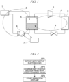
Fig. 1 is a piping system diagram of a cooling device according to a minimum configuration example of the present invention. -
Fig. 2 is a process diagram of a control method for a cooling device according to the minimum configuration example of the present invention. -
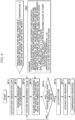
Fig. 3 is a flowchart of an operation of a control unit of a cooling device according to a first embodiment of the present invention. -
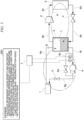
Fig. 4 is a piping system diagram illustrating an overall configuration of the cooling device according to the first embodiment of the present invention. -
Fig. 5 is a piping system diagram illustrating an overall configuration of a cooling device according to a second embodiment of the present invention. -
Fig. 6 is a flowchart of an operation of a control unit of a cooling device according to a third embodiment of the present invention. -
Fig. 7 is a piping system diagram illustrating an overall configuration of the cooling device according to the third embodiment of the present invention. -
Fig. 8 is a flowchart of an operation of a control unit of a cooling device according to a fourth embodiment of the present invention. -
Fig. 9 is a piping system diagram illustrating an overall configuration of the cooling device according to the fourth embodiment of the present invention. - A configuration of a cooling device according to a minimum configuration of the present invention will be described with reference to
Fig. 1 . This cooling device is a cooling device using a refrigeration cycle in which a refrigerant is circulated through aheat receiver 1, acompressor 2, aheat radiator 3, and anexpander 4, and includes atank 5 that separates the refrigerant supplied from theexpander 4 into a gas phase refrigerant and a liquid phase refrigerant, apump 6 that sends the liquid phase refrigerant separated in thetank 5 to theheat receiver 1, and acontrol unit 7 that controls the amount of increase in pressure of thecompressor 2 in the refrigeration cycle, in which thecontrol unit 7 controls the operation and stop of thepump 6, and starts the operation of the pump on condition that a net positive suction head of thepump 6 has reached a predetermined value or more. That is, thecompressor 2 is operated to decrease a temperature of the refrigerant flowing through a heat radiator side loop (a refrigerant circulation loop) indicated by an arrow A inFig. 1 , and then, the refrigerant is caused to flow through a heat receiver side loop (a refrigerant circulation loop) indicated by an arrow B inFig. 1 on condition that the net positive suction head has reached a predetermined value or more. - According to the above configuration, because the
pump 6 is activated by thecontrol unit 7 on condition that a pressure determined according to the net positive suction head of the refrigerant sucked into thepump 6, that is, a pressure determined according to a pressure measurement value of a refrigerant liquid (a liquid phase refrigerant) separated in thetank 5 and sucked into thepump 6, a head difference from a liquid level in thetank 5 to the pump 6 (a pressure generated by a density of the refrigerant liquid at a temperature at that point in time and gravity due to a difference in height), and a saturated vapor pressure of the refrigerant in thetank 5 is equal to or higher than a predetermined pressure, it is possible to maintain smooth circulation of the refrigerant in the cooling cycle without causing cavitation in the refrigerant liquid to be sucked. - An example of a calculation equation using parameters actually measured in the control of the
control unit 7 includes Equation (1) below.
- In a temperature range in which the present invention is implemented, because change in the density of the refrigerant liquid is negligibly small, the density can be treated as a constant in terms of control.
- A control method for a cooling device according to the minimum configuration of the present invention will be described with reference to
Fig. 2 . This control method for a cooling device is a control method for a cooling device using a refrigeration cycle in which a refrigerant is circulated through theheat receiver 1, thecompressor 2, theheat radiator 3, and theexpander 4, and thecontrol unit 7 controls an operation and stop of thepump 6 and starts the operation of thepump 6 on condition that the net positive suction head of thepump 6 has reached a predetermined value or more. That is, the cooling device is controlled so that the temperature of the refrigerant flowing through the heat radiator side loop (the refrigerant circulation loop) indicated by the arrow A inFig. 1 is decreased, and then, the refrigerant is caused to flow through the heat receiver side loop (the refrigerant circulation loop) indicated by the arrow B inFig. 1 on condition that the net positive suction head becomes the predetermined value or more. - An example of a more specific control step of the control method related to the minimum configuration is as follows.
- The
control unit 7 uses measurement data and known data for an inlet pressure of thepump 6, a detection value of the temperature, and a physical property value of the refrigerant (for example, a saturated vapor pressure at the temperature) as parameters, to detect the net positive suction head through calculation based on Equation (1) above. - The
control unit 7 compares the net positive suction head with a management value (a predetermined value) of the net positive suction head obtained in advance. - The
control unit 7 starts the operation of thepump 6 on condition that the net positive suction head exceeds the predetermined value. - According to the above configuration, because the
pump 6 is activated on condition that a pressure of the refrigerant liquid to be sucked is equal to or higher than a predetermined net positive suction head according to the saturated vapor pressure at that point in time, it is possible to prevent cavitation on the suction side of thepump 6 from occurring. - Hereinafter, a first embodiment of the present invention will be described with reference to
Figs. 3 and4 . InFig. 4 , the same components as those inFig. 1 are denoted by the same reference signs, and a description thereof will be simplified. - The
heat receiver 1 is provided in, for example, a ceiling-mounted unit disposed above a heat generation source such as an internal server of a server room or the like, and includes, for example, a pipe through which a refrigerant flows, and fins having a contact area necessary to promote heat exchange with an exhaust gas of a server that is a cooling target. Further, theheat receiver 1 functions as an evaporator that receives heat from the air that absorbs heat of an internal heat generation source by passing through the inside of the server, is discharged to a hot aisle side of the server room (a passage in the server room on the side from which cooling air having a raised temperature is discharged), and has become an updraft to be brought into contact with the fins, and the refrigerant flowing inside evaporates according to an amount of received heat. The refrigerant that has received the heat in theheat receiver 1 becomes a gas phase refrigerant according to the amount of received heat, and is discharged in a gas-liquid mixed phase state. - A
pipe 8a connects theheat receiver 1 to a gas-liquid separator (specifically, a closed tank, which is hereinafter referred to as a tank) 5, and apipe 8b connects the gas phase portion (an upper portion) of thetank 5 to the suction side of thecompressor 2. - A
pipe 8c connects a discharge side of thecompressor 2 to theheat radiator 3. Theheat radiator 3 is installed, for example, outside in a building including the server room, and radiates heat by heat-exchanging the refrigerant compressed by thecompressor 2 with, for example, an atmosphere, so that the refrigerant is below a boiling point and becomes a liquid phase refrigerant. - A
pipe 8d connects theheat radiator 3 to theexpansion valve 4. The refrigerant that has radiated the heat in theheat radiator 3 and become a liquid phase refrigerant expands in theexpansion valve 4 as an expander. - A
pipe 8e supplies the refrigerant that has expanded by theexpansion valve 4 and entered a gas-liquid mixed phase state to thetank 5. - A
pipe 8f connects a portion below a liquid level L of thetank 5 to the suction side of thepump 6, and apipe 8g connects a discharge side of thepump 6 to theheat receiver 1. A valve V that opens or closes a flow path of the refrigerant is provided in the middle of thepipe 8g. When a plurality ofheat receivers 1 are provided in parallel in one refrigeration cycle (a system of the refrigerant flowing through a heat receiver side loop B), it is possible to distribute a required amount of refrigerant according to the difference in amount of received heat between the plurality ofheat receivers 1 and the difference in flow path resistance of thepipe 8g directed to therespective heat receivers 1 by adjusting the degree of opening of each valve V provided in thepipe 8g directed to eachheat receiver 1. - The liquid phase refrigerant obtained by the gas-liquid separation in the
tank 5 is sucked into thepump 6 via thepipe 8f and supplied to theheat receiver 1 via thepipe 8g. Then, in theheat receiver 1, heat is received from a heat generation source such as an exhaust gas of the server, the refrigerant flows into thetank 5 again and circulates in the refrigeration cycle. - A temperature sensor T measures the temperature of the refrigerant at a position immediately before the refrigerant is sucked into the
pump 6 in the middle of thepipe 8f, and a pressure sensor P similarly measures the pressure of the refrigerant at the position immediately before the refrigerant is sucked into thepump 6. - The
control unit 7 controls the activation of thepump 6 from data of the temperature and the pressure supplied from the temperature sensor T and the pressure sensor P, and a calculation equation for a required suction head stored in a database DB1. Thedatabase DB 1 is mounted in a memory as a control program or stored data in thecontrol unit 7, or is stored in a server physically separated from thecontrol unit 7 and receives or sends data via a communication line. Details of control of thecontrol unit 7 will be described below together with an operation of the cooling device with reference toFig. 3 . - Control content of the
control unit 7 will be described together with an operation of the cooling device of the first embodiment having the configuration ofFig. 3 with reference to a flowchart ofFig. 3 . - Control is executed on condition that the
compressor 2 is activated so that the refrigerant circulates through the heat radiator side loop A. Theheat radiator 3 is activated, for example, by activating a fan (not illustrated) to supply cooling air (outside air) or by activating a pump (not illustrated) to supply cooling water, and is activated by opening the valve constituting theexpander 4 to a predetermined degree of opening. - The
control unit 7 controls a drive motor of thecompressor 2 to gradually increase the pressure of the refrigerant to a predetermined compression ratio. - The
control unit 7 acquires the data of the temperature and the pressure of the refrigerant on the inlet side of thepump 6 from the temperature sensor T and the pressure sensor P. - The
control unit 7 refers to the database DB to calculate a density of the refrigerant liquid and the saturated vapor pressure from the temperature supplied from the temperature sensor T. Further, thecontrol unit 7 calculates the required suction head according to
- In the calculation of the net positive suction head based on Equation (1) above, a pump inlet pressure P, a refrigerant temperature T decreases with the increase in pressure of the refrigerant by the
compressor 2, and the saturated vapor pressure decreases with a decrease in the refrigerant temperature. In the first embodiment, it is assumed that the density of the refrigerant is constant regardless of change in the refrigerant temperature T. - Further, a threshold value of the net positive suction head is calculated by using Equation (2) below.

- Here, the required suction head is the minimum suction pressure that does not cause cavitation, which is determined by performance characteristics of the pump 6 (a flow rate and pressure characteristics determined by design or obtained by actual measurement), and the coefficient f is a safety factor that is multiplied to reliably prevent cavitation in consideration of operating conditions or a measurement error.
- The
control unit 7 determines whether the net positive suction head has exceeded the threshold value, returns to SP13 and waits for the net positive suction head to increase in the case of No, and proceeds to the next step in the case of Yes. - The
control unit 7 activates thepump 6. - The
control unit 7 activates theheat receiver 1. Specifically, the valve V is opened so that the refrigerant sucked from thetank 5 is supplied to theheat receiver 1. Further, a fan (not illustrated) provided in theheat receiver 1 is activated, air in the server room is sucked and sent to theheat receiver 1, and the air exchanges the heat with the refrigerant. - The refrigerant circulates in the refrigeration cycle through the above steps, and the
compressor 2 continuously compresses the refrigerant. That is, an operation of the refrigeration cycle in which the refrigerant received in the heat receiver side loop B is compressed and heat-radiated in the heat radiator side loop A and supplied to the heat receiver side loop B again continues. - In the first embodiment, because the net positive suction head of the
pump 6 can be maintained above the required suction head, it is possible to stably supply the refrigerant from thepump 6 to theheat receiver 1 without causing cavitation immediately after the start of the operation of the refrigeration cycle. - A second embodiment of the present invention will be described with reference to
Fig. 5 . InFig. 5 , the same components as those inFigs. 1 and4 are denoted by the same reference signs and description thereof will be simplified. - In the second embodiment, a suction side and a discharge side of a
pump 6 are connected by a pipe (a bypass pipeline) 8h, and abypass valve 9a is provided in the middle of thepipe 8h. - Even in this second embodiment, the
control unit 7 performs control in the same processing steps SP11 to SP18 as the flowchart illustrated inFig. 3 that is executed in the first embodiment. - In the second embodiment, because an amount of refrigerant according to a degree of opening of the
bypass valve 9a can be circulated from the discharge side to the suction side of thepump 6 by thebypass pipeline 8h, it is possible to cause thepump 6 to suck the refrigerant having a flow rate equal to or higher than a predetermined value, which is difficult to cause the cavitation, and because the temperature rise of the refrigerant that repeatedly passes through thepump 6 due to the circulation of the refrigerant via thebypass pipeline 8h, that is, the temperature is measured by the temperature sensor T between a confluence portion of thebypass pipeline 8h and thepipe 8f and the suction side of thepump 6, it is possible to accurately reflect this rise of temperature in the saturated vapor pressure for each temperature in a calculation equation for a net positive suction head and accurately calculate the net positive suction head even when the temperature of the refrigerant rises with the circulation through thebypass pipeline 8h. - A third embodiment of the present invention will be described with reference to
Figs. 6 and7 . InFig. 7 , the same components as those inFigs. 1 ,4 , and5 are denoted by the same reference signs, and description thereof will be simplified. - In the fifth embodiment, the refrigerant temperature and refrigerant pressure in a
tank 5 are adopted instead of a refrigerant temperature and refrigerant pressure at an inlet of apump 6 of the first and second embodiments as parameters of the calculation equation for a net positive suction head that are used for control of thepump 6 by acontrol unit 7, and a liquid level height of the refrigerant in thetank 5 is used. - Specifically, the
tank 5 includes a temperature sensor T that detects the refrigerant temperature at a bottom (a position at which a liquid phase state is guaranteed), and a pressure sensor P that detects the refrigerant pressure at an upper portion (a position at which a gas phase state is guaranteed). Further, thetank 5 includes, at an upper portion, a liquid level sensor L that detects a liquid level sensor L of the liquid phase refrigerant stored in thetank 5. - That is, the
control unit 7 includes a database DB2 that receives measurement data from the pressure sensor P, the refrigerant temperature sensor T, and the liquid level sensor L to calculate the net positive suction head, and the database DB2 calculates the net positive suction head on the basis of Equation (1') below.
- The pipe pressure loss can be calculated by multiplying a flow rate of the refrigerant (determined by a flow velocity and a pipe diameter) by a predetermined pressure loss coefficient K.
- Control content of the
control unit 7 will be described together with an operation of the cooling device of the third embodiment with reference to a flowchart ofFig. 6 . - Control is started on condition that the refrigerant circulates through the heat radiator side loop A due to the activation of the
compressor 2. - The
control unit 7 controls a drive motor of thecompressor 2 to gradually increase the pressure of the refrigerant to a predetermined compression ratio. - The
control unit 7 acquires the data of the temperature and the pressure of the refrigerant in thetank 5 from the temperature sensor T and the pressure sensor P, and acquires the data of the liquid level in thetank 5 from the liquid level sensor L. - The
control unit 7 refers to the database DB2 to calculate the density of the refrigerant liquid and the saturated vapor pressure from the temperature supplied from the temperature sensor T. Further, thecontrol unit 7 calculates a required suction head according to
- In the calculation of the net positive suction head based on Equation (1') above, a refrigerant temperature T decreases with the increase in pressure of the refrigerant by the
compressor 2, and the saturated vapor pressure decreases with a decrease in the refrigerant temperature. Further, from the liquid level height, a pressure applied to the liquid level height in thetank 5 is reflected in the effective charging head. In the third embodiment, it is assumed that the density of the refrigerant is constant regardless of change in the refrigerant temperature T. - The
control unit 7 determines whether the net positive suction head has exceeded the threshold value obtained by Equation (2) common to the first and second embodiments, returns to SP13' and waits for the net positive suction head to rise in the case of No, and proceeds to the next step in the case of Yes. - The
control unit 7 activates thepump 6. - The
control unit 7 activates theheat receiver 1. Specifically, the valve V is opened so that the refrigerant sucked from thetank 5 is supplied to theheat receiver 1. Further, a fan (not illustrated) provided in theheat receiver 1 is activated, air in the server room is sucked and sent to theheat receiver 1, and the air exchanges the heat with the refrigerant. - The refrigerant circulates in the refrigeration cycle through the above steps, and the
compressor 2 continuously compresses the refrigerant. That is, an operation of the refrigeration cycle in which the refrigerant received in the heat receiver side loop B is compressed and heat-radiated in the heat radiator side loop A and supplied to the heat receiver side loop B again continues. - According to the above configuration, it is possible to calculate the required suction head that can prevent the occurrence of cavitation of the
pump 6, by using the data acquired by the sensors provided in order to measure the pressure, the temperature, and the liquid level in thetank 5 without separately providing sensors in thepipe 8f of a suction portion of thepump 6. - A fourth embodiment of the present invention will be described with reference to
Figs. 8 and9 . InFig. 9 , the same components as those inFigs. 1 ,4 , and7 are denoted by the same reference signs, and a description thereof will be simplified. - In the fourth embodiment, a
control unit 7 performs control according to a waiting time until the start of an operation of apump 6 stored in a database DB3. - A waiting time is determined on the basis of, for example, the amount of increase in pressure according to an operating time of the
compressor 2 until the pressure on the suction side of thepump 6 reaches the net positive suction head that does not cause cavitation on the basis of operation record data of the refrigeration cycle for each outside air temperature, and is calculated by Equation (3) below.
- KT is a time sufficient for the refrigerant temperature to begin to decrease with an increase in the pressure, and is an integer that is determined on the basis of operation record data for a degree of increase in pressure of the refrigeration cycle and occurrence or non-occurrence of the cavitation (an operation situation of the pump), and used for converting the amount of increase in pressure required for the compressor until the refrigerant temperature decreases into a waiting time.
- Control content of the
control unit 7 will be described together with an operation of the cooling device of the fourth embodiment with reference to the flowchart ofFig. 8 . - Control is executed on condition that the
compressor 2 is operated and the refrigerant is circulated in the refrigeration cycle. - The
control unit 7 controls a drive motor of thecompressor 2 to gradually increase the pressure of the refrigerant to a predetermined compression ratio. - The
control unit 7 acquires data of the waiting time calculated on the basis of Equation (3) above from the database DB3. - The
control unit 7 determines whether or not the waiting time exceeds a threshold value preset in the database DB3, waits Yes (the waiting time exceeds the threshold value), and proceeds to the next step. - The
control unit 7 activates thepump 6. - The
control unit 7 activates theheat receiver 1. Specifically, the valve V is opened so that the refrigerant sucked from thetank 5 is supplied to theheat receiver 1. Further, a fan (not illustrated) provided in theheat receiver 1 is activated, air in the server room is sucked and sent to theheat receiver 1, and the air exchanges the heat with the refrigerant. - The refrigerant circulates in the refrigeration cycle through the above steps, and the
compressor 2 continuously compresses the refrigerant. That is, an operation of the refrigeration cycle in which the refrigerant received in the heat receiver side loop B is compressed and heat-radiated in the heat radiator side loop A and supplied to the heat receiver side loop B again continues. - According to the above configuration, it is possible to prevent the occurrence of cavitation by waiting for the operation of the
pump 6 over a predetermined time when the pressure of the refrigerant is expected to reach the net positive suction head of thepump 6. Further, the control may be selected from a plurality of waiting time threshold values according to, for example, the outside air temperature according to seasonal factors, and the room temperature of the server room according to a variation in a load of a server that is a cooling target. Further, because this control is executed on the basis of the passage of a preset time, it is not necessary to provide sensors at various places of the refrigeration cycle to measure pressure, temperature, and the like, and it is possible to simplify the configuration of the refrigeration device. That is, it is possible to indirectly determine whether or not a condition that the net positive suction head has reached a predetermined pressure or higher is satisfied, by using a measurement value of time. - Specific configurations of the heat receiver, the compressor, the heat radiator, the gas-liquid separator, the expander, the pump, and the control unit that constitute the refrigeration cycle are not limited to the embodiments and, of course, may be changed without departing from the gist of the present invention. For example, the expander can have a function of depressurizing and expanding a refrigerant in a flow path of the liquid phase refrigerant by applying a throttle to the flow path, and an orifice (simply, a throttle) or a capillary (which is a thin tube having a predetermined length formed in a coil shape, and gives resistance to a fluid by flowing through a flow path having a small cross-sectional area) can be adopted, in addition to the valve in the embodiment.
- Further, activation control for the
pump 6 that is performed in the first to fourth embodiments is not limited to a single implementation, and a plurality of controls may be implemented in combination. Further, when the plurality of controls may be implemented in combination, any one of the controls may be preferentially executed in consideration of conditions such as a response speed to an increase or decrease of the net positive suction head, and an influence on loads of refrigeration cycles of other systems. - The cooling device and cooling method of the present invention can be used for air conditioning for a data center and the like.
-
- 1 Heat receiver
- 2 Compressor
- 3 Heat radiator
- 3a Fan
- 3b Cooling air adjustment plate
- 4 Expander
- 5 Gas-liquid separator (tank)
- 6 Pump
- 7 Control unit
- 8a, 8b, 8c, 8d, 8e, 8f, 8g, 8h Pipe
- 9a Bypass valve
- DB1, DB1', DB2, DB3 Database
- T Temperature sensor
- P Pressure sensor
- L Liquid level sensor
- V Valve
Claims (8)
- A cooling device using a refrigeration cycle in which a refrigerant is circulated through a heat receiver, a compressor, a heat radiator, and an expansion valve, the cooling device comprising:a gas-liquid separator configured to perform gas-liquid separation on the refrigerant supplied from the expansion valve;a pump configured to send a liquid phase refrigerant separated by the gas-liquid separator to the heat receiver; anda control unit configured to control opening and closing of a refrigerant flow path of the refrigeration cycle, and an operation and stop of the compressor and the pump,wherein the control unit starts the operation of the pump on condition that a net positive suction head of the pump has reached a predetermined value or more.
- The cooling device according to claim 1, wherein the control unit calculates the net positive suction head using a pressure between the pump and the gas-liquid separator, a saturated vapor pressure of the refrigerant, and a liquid density of the refrigerant.
- The cooling device according to claim 1, wherein the control unit calculates the net positive suction head from detection data of a pressure sensor and a temperature sensor, the pressure sensor being configured to measure a pressure of a liquid phase portion between the pump and the gas-liquid separator, the temperature sensor being configured to measure a temperature of the refrigerant.
- The cooling device according to claim 1, wherein the control unit calculates the net positive suction head from detection data of a pressure sensor and a temperature sensor, the pressure sensor being configured to measure a pressure of a liquid phase portion between the pump and the gas-liquid separator and inside a bypass valve pipe configured to connect a front and a rear of the pump, the temperature sensor being configured to measure a temperature of the refrigerant.
- The cooling device according to claim 1, wherein the control unit calculates the net positive suction head using a liquid level height inside the gas-liquid separator, a pressure of a gas phase portion, a saturated vapor pressure of the refrigerant, and a density of the refrigerant.
- The cooling device according to claim 1, wherein the control unit calculates the net positive suction head from detection data of a liquid level sensor, a pressure sensor and a temperature sensor, the liquid level sensor being configured to measure a liquid level of the gas-liquid separator, the pressure sensor being configured to measure a pressure of a gas phase portion of the gas-liquid separator, the temperature sensor being configured to measure a temperature of the refrigerant in the gas-liquid separator.
- The cooling device according to claim 1, wherein the control unit starts an operation of the pump on condition that a predetermined time has elapsed after activation of the compressor.
- A control method for a cooling device using a refrigeration cycle in which a refrigerant is circulated through a heat receiver, a compressor, a heat radiator, and an expansion valve, the control method comprising:controlling, by a control unit, an operation of a pump configured to send, to the heat receiver, a liquid phase refrigerant separated by a gas-liquid separator configured to perform gas-liquid separation on the refrigerant supplied from the expansion valve; andstarting, by the control unit, the operation of the pump on condition that a net positive suction head of the pump has reached a predetermined value or more.
Applications Claiming Priority (1)
| Application Number | Priority Date | Filing Date | Title |
|---|---|---|---|
| PCT/JP2021/033539 WO2023037543A1 (en) | 2021-09-13 | 2021-09-13 | Cooling device and method for controlling cooling device |
Publications (2)
| Publication Number | Publication Date |
|---|---|
| EP4174402A4 EP4174402A4 (en) | 2023-05-03 |
| EP4174402A1 true EP4174402A1 (en) | 2023-05-03 |
Family
ID=81291672
Family Applications (1)
| Application Number | Title | Priority Date | Filing Date |
|---|---|---|---|
| EP21908078.5A Withdrawn EP4174402A1 (en) | 2021-09-13 | 2021-09-13 | Cooling device and method for controlling cooling device |
Country Status (5)
| Country | Link |
|---|---|
| US (1) | US20230213253A1 (en) |
| EP (1) | EP4174402A1 (en) |
| JP (2) | JP7056814B1 (en) |
| AU (1) | AU2021398579A1 (en) |
| WO (1) | WO2023037543A1 (en) |
Family Cites Families (8)
| Publication number | Priority date | Publication date | Assignee | Title |
|---|---|---|---|---|
| JP4832544B2 (en) * | 2009-04-08 | 2011-12-07 | 三菱電機株式会社 | Refrigeration cycle equipment |
| US20140250886A1 (en) * | 2011-09-30 | 2014-09-11 | Sanden Corporation | Rankine Cycle |
| JP5929464B2 (en) * | 2012-04-20 | 2016-06-08 | 株式会社Ihi | Heat pump and heat pump activation method |
| JP6566705B2 (en) | 2015-04-28 | 2019-08-28 | 日立ジョンソンコントロールズ空調株式会社 | Air conditioner |
| JP2018146144A (en) * | 2017-03-02 | 2018-09-20 | パナソニックIpマネジメント株式会社 | Refrigeration cycle apparatus and operation method thereof |
| DE102018101514B4 (en) * | 2018-01-24 | 2021-07-29 | Hanon Systems | Motor vehicle refrigeration system with several evaporators of different cooling capacities |
| JP7152683B2 (en) * | 2018-09-11 | 2022-10-13 | ダイキン工業株式会社 | magnetic refrigerator |
| US11719261B2 (en) * | 2018-10-04 | 2023-08-08 | Purdue Research Foundation | Vapor-pressure driven pump |
-
2021
- 2021-09-13 JP JP2022510104A patent/JP7056814B1/en not_active Expired - Fee Related
- 2021-09-13 AU AU2021398579A patent/AU2021398579A1/en not_active Abandoned
- 2021-09-13 EP EP21908078.5A patent/EP4174402A1/en not_active Withdrawn
- 2021-09-13 WO PCT/JP2021/033539 patent/WO2023037543A1/en not_active Ceased
- 2021-09-13 US US17/788,888 patent/US20230213253A1/en not_active Abandoned
-
2022
- 2022-03-31 JP JP2022058360A patent/JP2023041593A/en active Pending
Also Published As
| Publication number | Publication date |
|---|---|
| WO2023037543A1 (en) | 2023-03-16 |
| JP2023041593A (en) | 2023-03-24 |
| US20230213253A1 (en) | 2023-07-06 |
| JP7056814B1 (en) | 2022-04-19 |
| JPWO2023037543A1 (en) | 2023-03-16 |
| AU2021398579A1 (en) | 2023-03-30 |
Similar Documents
| Publication | Publication Date | Title |
|---|---|---|
| US10941964B2 (en) | Method for operating a vapour compression system with a receiver | |
| EP2162689B1 (en) | Method and apparatus for equalizing a pumped refrigerant system | |
| JP6589946B2 (en) | Refrigeration equipment | |
| US20170059219A1 (en) | System and Method to Optimize Effectiveness of Liquid Line Accumulator | |
| JP2011521194A (en) | Filling management in refrigerant vapor compression systems. | |
| EP3589900B1 (en) | A method for controlling ejector capacity in a vapour compression system | |
| CN108759178B (en) | Liquid level control method and refrigeration cycle system of flooded evaporator | |
| CN112534196B (en) | Method for controlling a vapour compression system at reduced suction pressure | |
| CN110573810A (en) | Vapor Compression System with Suction Line Liquid Separator | |
| US11499768B2 (en) | Chiller suction flow limiting with input power or motor current control | |
| EP4174402A1 (en) | Cooling device and method for controlling cooling device | |
| CN107024013A (en) | Air conditioner and control method thereof | |
| CN106801921B (en) | Jet enthalpy air conditioning system and its control method | |
| CN112513542B (en) | Method for controlling a vapor compression system based on a predicted flow | |
| WO2016150664A1 (en) | A method for controlling compressor capacity in a vapour compression system | |
| US20240255201A1 (en) | Cooling device and control method for cooling device | |
| CN103925727A (en) | Freezing System And Heat Source System | |
| KR20100062117A (en) | Air conditioner having plate heat exchanger and controlling method of the same of | |
| JP2005048982A (en) | Refrigeration unit | |
| WO2026088390A1 (en) | Air conditioner and control method | |
| WO2023042906A1 (en) | Cooling device and cavitation prevention method | |
| CN117515985A (en) | Control method and device of refrigeration system, refrigeration system and storage medium | |
| JP2022076215A (en) | Cooling device and cooling method | |
| JPH05322369A (en) | Heat pump of a plurality of heat source type |
Legal Events
| Date | Code | Title | Description |
|---|---|---|---|
| STAA | Information on the status of an ep patent application or granted ep patent |
Free format text: STATUS: UNKNOWN |
|
| STAA | Information on the status of an ep patent application or granted ep patent |
Free format text: STATUS: THE INTERNATIONAL PUBLICATION HAS BEEN MADE |
|
| PUAI | Public reference made under article 153(3) epc to a published international application that has entered the european phase |
Free format text: ORIGINAL CODE: 0009012 |
|
| STAA | Information on the status of an ep patent application or granted ep patent |
Free format text: STATUS: REQUEST FOR EXAMINATION WAS MADE |
|
| 17P | Request for examination filed |
Effective date: 20220628 |
|
| A4 | Supplementary search report drawn up and despatched |
Effective date: 20221208 |
|
| AK | Designated contracting states |
Kind code of ref document: A1 Designated state(s): AL AT BE BG CH CY CZ DE DK EE ES FI FR GB GR HR HU IE IS IT LI LT LU LV MC MK MT NL NO PL PT RO RS SE SI SK SM TR |
|
| STAA | Information on the status of an ep patent application or granted ep patent |
Free format text: STATUS: THE APPLICATION IS DEEMED TO BE WITHDRAWN |
|
| 18D | Application deemed to be withdrawn |
Effective date: 20230714 |