EP4174401B1 - Verfahren zur prädiktiven steuerung der ausrichtung eines sonnenverfolgers - Google Patents
Verfahren zur prädiktiven steuerung der ausrichtung eines sonnenverfolgers Download PDFInfo
- Publication number
- EP4174401B1 EP4174401B1 EP22216183.8A EP22216183A EP4174401B1 EP 4174401 B1 EP4174401 B1 EP 4174401B1 EP 22216183 A EP22216183 A EP 22216183A EP 4174401 B1 EP4174401 B1 EP 4174401B1
- Authority
- EP
- European Patent Office
- Prior art keywords
- solar
- inclination angle
- solar tracker
- evolution
- orientation
- Prior art date
- Legal status (The legal status is an assumption and is not a legal conclusion. Google has not performed a legal analysis and makes no representation as to the accuracy of the status listed.)
- Active
Links
Images


Classifications
-
- H—ELECTRICITY
- H02—GENERATION; CONVERSION OR DISTRIBUTION OF ELECTRIC POWER
- H02S—GENERATION OF ELECTRIC POWER BY CONVERSION OF INFRARED RADIATION, VISIBLE LIGHT OR ULTRAVIOLET LIGHT, e.g. USING PHOTOVOLTAIC [PV] MODULES
- H02S20/00—Supporting structures for PV modules
- H02S20/30—Supporting structures being movable or adjustable, e.g. for angle adjustment
- H02S20/32—Supporting structures being movable or adjustable, e.g. for angle adjustment specially adapted for solar tracking
-
- F—MECHANICAL ENGINEERING; LIGHTING; HEATING; WEAPONS; BLASTING
- F24—HEATING; RANGES; VENTILATING
- F24S—SOLAR HEAT COLLECTORS; SOLAR HEAT SYSTEMS
- F24S25/00—Arrangement of stationary mountings or supports for solar heat collector modules
- F24S25/10—Arrangement of stationary mountings or supports for solar heat collector modules extending in directions away from a supporting surface
- F24S25/12—Arrangement of stationary mountings or supports for solar heat collector modules extending in directions away from a supporting surface using posts in combination with upper profiles
-
- F—MECHANICAL ENGINEERING; LIGHTING; HEATING; WEAPONS; BLASTING
- F24—HEATING; RANGES; VENTILATING
- F24S—SOLAR HEAT COLLECTORS; SOLAR HEAT SYSTEMS
- F24S30/00—Arrangements for moving or orienting solar heat collector modules
- F24S30/40—Arrangements for moving or orienting solar heat collector modules for rotary movement
- F24S30/42—Arrangements for moving or orienting solar heat collector modules for rotary movement with only one rotation axis
- F24S30/425—Horizontal axis
-
- F—MECHANICAL ENGINEERING; LIGHTING; HEATING; WEAPONS; BLASTING
- F24—HEATING; RANGES; VENTILATING
- F24S—SOLAR HEAT COLLECTORS; SOLAR HEAT SYSTEMS
- F24S50/00—Arrangements for controlling solar heat collectors
-
- F—MECHANICAL ENGINEERING; LIGHTING; HEATING; WEAPONS; BLASTING
- F24—HEATING; RANGES; VENTILATING
- F24S—SOLAR HEAT COLLECTORS; SOLAR HEAT SYSTEMS
- F24S50/00—Arrangements for controlling solar heat collectors
- F24S50/20—Arrangements for controlling solar heat collectors for tracking
-
- F—MECHANICAL ENGINEERING; LIGHTING; HEATING; WEAPONS; BLASTING
- F24—HEATING; RANGES; VENTILATING
- F24S—SOLAR HEAT COLLECTORS; SOLAR HEAT SYSTEMS
- F24S50/00—Arrangements for controlling solar heat collectors
- F24S50/80—Arrangements for controlling solar heat collectors for controlling collection or absorption of solar radiation
-
- G—PHYSICS
- G05—CONTROLLING; REGULATING
- G05B—CONTROL OR REGULATING SYSTEMS IN GENERAL; FUNCTIONAL ELEMENTS OF SUCH SYSTEMS; MONITORING OR TESTING ARRANGEMENTS FOR SUCH SYSTEMS OR ELEMENTS
- G05B15/00—Systems controlled by a computer
- G05B15/02—Systems controlled by a computer electric
-
- F—MECHANICAL ENGINEERING; LIGHTING; HEATING; WEAPONS; BLASTING
- F24—HEATING; RANGES; VENTILATING
- F24S—SOLAR HEAT COLLECTORS; SOLAR HEAT SYSTEMS
- F24S2201/00—Prediction; Simulation
-
- Y—GENERAL TAGGING OF NEW TECHNOLOGICAL DEVELOPMENTS; GENERAL TAGGING OF CROSS-SECTIONAL TECHNOLOGIES SPANNING OVER SEVERAL SECTIONS OF THE IPC; TECHNICAL SUBJECTS COVERED BY FORMER USPC CROSS-REFERENCE ART COLLECTIONS [XRACs] AND DIGESTS
- Y02—TECHNOLOGIES OR APPLICATIONS FOR MITIGATION OR ADAPTATION AGAINST CLIMATE CHANGE
- Y02E—REDUCTION OF GREENHOUSE GAS [GHG] EMISSIONS, RELATED TO ENERGY GENERATION, TRANSMISSION OR DISTRIBUTION
- Y02E10/00—Energy generation through renewable energy sources
- Y02E10/40—Solar thermal energy, e.g. solar towers
- Y02E10/47—Mountings or tracking
Definitions
- the present invention relates to a method for controlling the orientation of a single-axis solar tracker, as well as to a single-axis solar tracker designed for implementing such a method.
- the invention relates to the field of solar trackers, otherwise known as tracking support systems or "solar trackers", intended to support solar sensors, generally of the photovoltaic panel type.
- single-axis solar trackers i.e. those that can be oriented along a single main axis of rotation, for a rotation that allows the sun to be followed as it rises and falls from east to west.
- a main axis of rotation generally extends horizontally and substantially parallel to the ground on which the solar tracker is anchored.
- US 2011/158467 A1 discloses a method for controlling the orientation of a single-axis solar tracker which can be steered around an axis of rotation, said method implementing the following steps: observing the evolution over time of the cloud cover above the solar tracker, by observing the cloud cover at several consecutive times using a sky observation system above the solar tracker; translating each observation made by the observation system into a map of the solar luminance and determining the evolution over time of an optimal tilt angle of the solar tracker corresponding substantially to a maximum of solar radiation on the solar tracker, as a function of the observed cloud cover, by calculating for each map at each time an optimal tilt angle associated with a maximum of solar luminance on said map; and controlling the orientation of the solar tracker as a function of the previous evolution of the optimal tilt angle.
- US 2011/220091 A1 discloses that representative images of cloud shadows relative to a field of heliostats can be used to adjust the operation of a solar energy system.
- US 2010/139644 A1 discloses embodiments relate to solar energy systems and methods of operation thereof.
- the solar energy system comprising: a plurality of heliostats configured to reflect sunlight onto a target mounted on a tower, each heliostat comprising a respective heliostat controller, the target being selected from the group consisting of an energy conversion target.
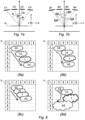
- Diagram (1 a) illustrates ideal weather conditions, in the absence of clouds, and the solar trackers ST are oriented facing the sun SO in order to benefit from maximum direct solar radiation Rdir.
- the control on the position of the sun SO provides maximum operation; such control corresponding to a control of the orientation of the solar tracker on a so-called direct inclination angle defined by the direction of the direct solar radiation Rdir at the level of the solar tracker.
- Diagrams (1 b), (1 c) and (1 d) illustrate degraded weather conditions, with different cloud cover depending in particular on the cloud surface or covered surface, the types of NU clouds present, the number and position of NU clouds relative to the SW sun.
- the sun position servo-control SO may not provide the best performance, by not taking into account the diffuse solar radiation Rdif.
- Diffuse solar radiation Rdif occurs when direct solar radiation Rdir is scattered in NU clouds and atmospheric particles.
- Diffuse solar radiation Rdif results from the diffraction of light by NU clouds and various molecules suspended in the atmosphere. Diffuse solar radiation Rdif therefore does not necessarily follow the direction defined by the sun SO towards the observation point on the Earth's surface.
- the ST solar trackers are precisely oriented according to diffuse tilt angles distinct from the direct tilt angle, in order to offer optimal efficiency.
- the person skilled in the art would be tempted to control, in real time, the orientation of the solar tracker to an optimal tilt angle corresponding to maximum solar radiation.
- the optimal tilt angle would correspond to the direct tilt angle and, in the presence of cloud cover or even a single cloud in front of the sun, the optimal tilt angle would correspond to a diffuse tilt angle. To do this, it would be sufficient to measure the amplitude of the radiation in different directions, and to establish the direction corresponding to a maximum amplitude to deduce the optimal tilt angle.
- the solar tracker may have to change orientation more or less often and more or less quickly.
- each change of orientation requires at least one actuator (generally an electric motor), generating electrical consumption and wear on the mechanical components affected by the change of orientation (bearings, rotating guide elements, etc.). This electrical consumption and wear will not necessarily be offset by the productivity gains obtained by adjusting to the optimal tilt angle in real time.
- the optimal tilt angle corresponds to the direct tilt angle
- the optimal tilt angle will be modified during these few minutes and then recover the direct tilt angle.
- Servoing the orientation of the solar tracker in real time to the optimal tilt angle would, in this case, lead to moving the solar tracker during these few minutes, for a benefit that is certainly very low in relation to the electrical consumption of the actuator(s) and the wear.
- the present invention aims to resolve these drawbacks by proposing a method for controlling the orientation of a single-axis solar tracker, implementing a step of predicting the evolution of the cloud cover so as not to systematically control the orientation of the solar tracker on the optimal tilt angle, but to anticipate the evolution of this optimal tilt angle to apply an advantageous compromise between the gains in productivity in solar energy and the losses in electrical consumption of the actuator(s), and possibly taking into account the wear caused by the changes in orientation.
- the method implements a forecast, in the more or less short term, of the future evolution of the optimal inclination angle; this optimal inclination angle corresponding, as a reminder, to the inclination angle of the solar tracker which offers the highest solar luminance as a function of the cloud cover, this optimal inclination angle being able to correspond either to the direct inclination angle (in particular in the absence of cloud, or at least in the absence of cloud between the sun and the solar tracker) or to a diffuse inclination angle which will depend on the composition of the cloud layer (number, size and types of clouds, location of clouds, cloud surface).
- a control of the orientation of the solar tracker can be implemented in an anticipatory manner, without directly following the optimal tilt angle in real time, thus making it possible to avoid changes in orientation which would provide little energy gain, or even cause energy losses, as would be the case for example if a single cloud passes in front of the sun for a short time.
- the observation of cloud cover is translated into a solar luminance map and this map is used to determine the optimal tilt angle.
- the map corresponds in fact to a distribution of the luminance according to several elevation angles (angles generally measured with respect to a vertical axis, these elevation angles being directly related to the tilt angle of the solar tracker), and the search for the optimal tilt angle corresponds to the search for an elevation angle associated with a maximum of solar luminance in the map.
- the mapping is one-dimensional, in other words with a distribution of the luminance only according to several elevation angles, or the mapping can be two-dimensional, in other words with a distribution of the luminance according to several elevation angles and also according to several azimuth angles (thus making it possible to take into account the width of the solar collector - dimension taken in a direction orthogonal to the axis of rotation - and not only the length of the solar collector - dimension taken in the direction of the axis of rotation -).
- the observation of cloud cover is converted into a map of the solar luminance received by an observation system, this solar luminance varying according to the observation angle.
- the maps make it possible to observe the evolution of the solar luminance (directly dependent on the evolution of the cloud layer), then to establish cartographic forecasts on the future state of the solar luminance map, and therefore on the inclination angle which would allow the solar tracker to benefit, in the future, from maximum luminance.
- the calculation of the optimal tilt angle is based on the calculation of perceived luminance values associated with each band and therefore with each tilt angle.
- the first direction is parallel to the axis of rotation of the solar tracker and the second direction is horizontal and orthogonal to the first direction.
- the observation corresponds to an image.
- the observation corresponds to a matrix of measurements made individually by each photosensitive cell, these photosensitive cells being positioned at different angles of inclination, and in particular distributed on a support in the shape of a hemispherical dome in order to offer a wide observation of the sky.
- the observation corresponds to a satellite image of the area concerned.
- a frequency weighting step is implemented, applied to the observation, which is a function of both a frequency response of the observation system and a frequency band useful to the solar sensor.
- frequency weighting will consist of applying a frequency filter which will take into account the spectral response of the solar sensor.
- the optimal inclination angle for a predictive map is calculated using a calculation method equivalent to that used during step b) to calculate the optimal inclination angle for a map.
- the same type of calculation is implemented to determine the optimal tilt angle, whether for the observations actually made or for the forecasts that come from a forward calculation, in order to guarantee a match between the calculations.
- step e the control of the orientation of the solar tracker is also carried out as a function of the energy consumption necessary to modify the orientation of the solar tracker starting from a present tilt angle until reaching a forecast optimal tilt angle established at a future instant during step d).
- the effective control takes into account this energy consumption in order to implement or not an orientation according to an optimal future (or forecast) tilt angle in order to anticipate a change in cloud cover.
- step e) the control of the orientation of the solar tracker is also carried out as a function of a so-called direct inclination angle established by an astronomical calculation of the position of the sun.
- the orientation angle present in the above scenario can correspond to the direct tilt angle, and the control will take into account the calculated potential energy efficiency in the event of a change direct tilt angle orientation to the predicted optimal tilt angle.
- step e) the control of the orientation of the solar tracker is also carried out as a function of a wear rate of mechanical members of the solar tracker stressed during a change of orientation of the solar tracker starting from a present angle of inclination until reaching a forecast optimal angle of inclination established at a future instant during step d).
- the invention also relates to a single-axis solar tracker orientable around an axis of rotation, of the type comprising a fixed structure for anchoring to the ground and a platform capable of supporting at least one solar collector, said platform being operable in rotation on the fixed structure along said axis of rotation by means of an actuation system, said solar tracker being remarkable in that it further comprises a system for observing the evolution over time of the cloud cover above the solar tracker and a control unit in connection, on the one hand, with the observation system to receive its observation data and, on the other hand, with the actuation system to control the rotation of the platform, where said control unit is configured to implement steps b) to e) of the control method as described above.
- a single-axis solar tracker 1 orientable around an axis of rotation A, of the type comprising a fixed structure 11 for anchoring to the ground consisting of one or more pylons anchored to the ground, for example by driving, screwing, bolting, ballast, or other equivalent means making it possible to fix and stabilize the fixed structure 11 to the ground.
- the solar tracker 1 further comprises a mobile platform 12 mounted for rotation on the fixed structure 11 along the axis of rotation A, and more specifically mounted for rotation on the upper ends of the pylons.
- This platform 12 is capable of supporting at least one solar collector 13, and in particular one or more photovoltaic panels.
- the rotation axis A is substantially horizontal and directed along a longitudinal axis X in the north-south direction.
- the platform 12 extends along a horizontal plane defined by the longitudinal axis X and by a transverse axis Y in the east-west direction, orthogonally to a vertical axis Z.
- the tilt angle of the solar tracker 1 corresponds to the angle of the normal to the platform 12 with respect to the vertical axis Z taken in the plane (Y, Z).
- this tilt angle is 0 degrees.
- the solar tracker 1 also comprises an observation system 2 for observing the cloud cover above the solar tracker 1, in other words for observing the sky above the solar tracker 1.
- This observation system 2 can be associated with a single solar tracker 1 or, economically, be shared with several solar trackers.
- the observation system 2 is fixed, and can be raised above the ground by being mounted for example on a pole 20.
- the solar tracker 1 further comprises an actuation system (not shown in the Figure 2 and bearing the numerical reference 3 on the Figure 10 ) which ensures the rotation of the platform 12 along the rotation axis A.
- This actuation system 3 comprises an actuator, for example of the cylinder type (electric, pneumatic or hydraulic) or electric motor (for example rotary motor).
- This actuation system 3 further comprises a mechanical system for transmitting the movement at the output of the actuator (rotary movement for a rotary motor, or linear movement for a cylinder) into a rotational movement of the platform 12.
- This mechanical transmission system may be, by way of non-limiting example, a deformable parallelogram system, a pulley return system, a pinion system, a chain system, a belt system, a dog system, a system with a transmission shaft, a connecting rod system, etc.
- the actuator is specific to the solar tracker 1, or is shared between several solar trackers.
- the platforms 12 of the different solar trackers are advantageously coupled in rotation, for synchronous rotation under the effect of the common actuator.
- the solar tracker 1 also comprises a control unit 4 of the electronic card type, which is connected to the observation system 2 in order to receive its observations (or observation data) and which is also connected to the actuation system 3 to control its operation and thus control the rotation of the platform 12, in other words the orientation of the solar tracker 1.
- this control unit 4 can be specific to the solar tracker 1, or be shared between several solar trackers, and preference between several solar trackers grouped in a line (extending from north to south) within linear solar installations.
- the observation system 2 comprises a support 21, in particular in the shape of a hemispherical dome, supporting photosensitive cells 22.
- These photosensitive cells 22 are positioned along several strips (or lines) distributed according to several so-called elevation angles ⁇ i which are measured with respect to the vertical axis Z in the plane (Y, Z), the reference mark (X, Y, Z) being centered on the center O of the hemispherical dome 21.
- the elevation angle ⁇ i is therefore to be compared with the angle of inclination of the solar tracker 1.
- These elevation angles ⁇ i are also visible on the Figure 7b .
- each strip there are one or more photosensitive cells 22.
- the photosensitive cells 22 of the same strip are distributed according to several so-called azimuth angles Rj which are measured with respect to the vertical axis Z in the plane (X, Z).
- the photosensitive cells 22 are also distributed according to columns at different azimuth angles Rj. These azimuth angles Rj are visible on the Figure 7a .
- These photosensitive cells 22 can be of the same technology as the photovoltaic panels 13 in order to be able to apply a weighting dependent on the useful wavelength range to the photovoltaic panels 13. Preferably, these photosensitive cells 22 will be subject to prior calibration to obtain better precision.
- the mapping module 40 converts an observation made by the observation system 2 into a mapping 5 of solar luminance.
- first observation system 2 On the Figure 4 on the left, an example of a first observation system 2 is illustrated schematically in a flat manner and comprises nine photosensitive cells 22 distributed according to three bands B1, B2, B3 which are associated with three elevation angles (or inclination angles), and according to three columns C1, C2, C3 which are associated with three azimuth angles.
- To this first observation system 2 corresponds a cartography 5 with three bands 50(1), 50(2), 50(3) and three columns 51(1), 51(2), 51(3), and where the solar luminance values are expressed relatively as a percentage.
- the observation system 2 comprises a camera, in particular of the hemispherical camera type, in order to extract images of the sky.
- the second observation system 2 (hereinafter called the camera) is configured to take images in a spectral width sufficient for the technology of the solar sensors 13, and in particular of the photovoltaic panel(s).
- the camera 2 delivers a raw IMB image of the sky which is then delivered to the mapping module 40 to convert this raw IMB image (or observation) into a two-dimensional map of the solar luminance.
- This two-dimensional raw IMB image is associated with a reference (X, Y), these X and Y axes having already been defined above.
- the mapping module 40 implements a succession of image processing steps to go from the raw image IMB to the mapping 5.
- the mapping module 40 implements a frequency weighting applied to the recovered raw image IMB (or video signal), to obtain a so-called weighted image IMP; this frequency weighting consists of applying a frequency filter to the observation (either the observation made by the photosensitive cells 22 or the observation made by the camera) which is a function of both the frequency response of the observation system 2 (whether the photosensitive cells 22 or the camera) and the useful frequency band (or spectral response) to the photovoltaic panels 13.
- the cartographic module 40 implements a processing of the weighted image IMP consisting of correcting the image of defects (noise suppression processing, glare or "blooming" processing, saturation processing, etc.) to obtain a so-called IMT processed image. Then, the cartographic module 40 implements a calculation (either pixel by pixel, or zone by zone where each zone comprises several pixels) of the distribution of the solar luminance on the IMT processed image in order to generate an initial mapping CI forming a map (or matrix) of solar luminance distributed according to several bands respectively associated with different elevation or inclination angles ⁇ (i) and according to several columns respectively associated with different azimuth angles; such an initial mapping being equivalent to that already described above. On the Figure 6 , the solar luminance values of the initial CI mapping are expressed relatively as a percentage.
- the mapping module 40 applies to the initial mapping CI a coefficient dependent on the variation in the sensitivity of the camera 2, in order to generate a mapping 5 of the same type as the mapping described above.
- the amplitude (or brightness) of the data delivered by the camera 2 is proportionally linked to the value of the solar radiation, so that this coefficient takes into account this proportionality dependent on the variation in the sensitivity of the camera 2.
- the cartographic module 40 generates a map 5 forming a map (or matrix) of solar luminance distributed according to several bands 50(i) associated respectively with different elevation angles or of inclination ⁇ i and according to several columns 51(j) associated respectively with different azimuth angles Rj.
- mapping 5 comprises five bands 50(1), ..., 50(5) and seven columns 51(1), ..., 51(7), and the solar luminance values are expressed relatively as a percentage.
- the resolution of the mapping 5 (in other words the number of bands and columns) and therefore the angular precision depend on the fineness of the image processing implemented by the mapping module 40, and also on the sensitivity and resolution of the observation system 2.
- this sensitivity depends on the sensitivity of the photosensitive cells 22, and this resolution depends on the number and distribution of the photosensitive cells 22.
- this sensitivity and this resolution depend on the quality of the camera.
- the optimal tilt angle calculation module 43 implements a calculation based on this mapping 5 to extract an optimal tilt angle ⁇ opt which corresponds to the tilt angle (or elevation angle) with which a maximum solar luminance is associated.
- the optimal inclination angle calculation module 43 implements a succession of sub-steps.
- This succession of sub-steps constitutes an example of a calculation method or algorithm, and the invention cannot of course be limited to this example.
- the optimal tilt angle calculation module 43 calculates, for each band 50(i) of the mapping 5, an equivalent luminance value Leq(i) from all the luminance values L(i, j) taken in the band 50(i).
- the coefficient takes into account that, beyond an angular deviation of 90 degrees, the radiation is not received by the flat solar collector(s).
- the optimal tilt angle calculation module 43 retains the optimal tilt angle ⁇ opt as being the tilt (or elevation) angle associated with the band having the highest perceived luminance value Lperc(i).
- the forecast calculation module 42 calculates forecast maps 6 of the solar luminance for future instants (t+nP), where n is a non-zero integer and P is the period of the observation carried out periodically and repetitively by the observation system 2. These forecast maps 6 are established on the basis of the maps 5 generated in real time by the cartographic module 40 and on the basis of the past maps 5 archived in the archiving module 41.
- FIG 8 illustrates four examples of a situation of cloud cover evolving over time, with four diagrams 8a, 8b, 8c and 8d each representing an image with the representation of a cloud observed at a past instant (t-2), of the same cloud observed at a past instant (t-1), of the same cloud observed at a present instant (t) and of the same cloud predicted by forecast calculation at a future instant (t+1) (the period P is worth 1 on the figure 8 ).
- the forecast calculation is based on taking into account the past evolution of solar luminance, between several past moments and the present moment, and in particular the evolution of the distribution of solar luminance and the speed of evolution of solar luminance.
- This forecast calculation can be based on a sliding time window, that is, a window including a predefined number of the last past maps.
- This forecast calculation is used to establish short-term forecast maps 6 (or map forecasts).
- short-term covers calculations over a future horizon of a maximum of ten to thirty minutes, or even a maximum of one to two hours. It is of course possible to provide longer-term predictive calculations.
- the algorithm implemented for such a forecast calculation can also take into account the evolution of the position of the sun in the sky, in particular if the forecast calculation is done for future moments sufficiently far away (for example beyond 30 minutes) so that the change in the position of the sun has an influence on the evolution of the solar luminance.
- This consideration of the position of the sun in the forecast calculation is illustrated by the broken connecting arrow on the Figure 10 between the forecast calculation module 42 and the astronomical calculation module 46.
- the forecast calculation module 42 establishes forecast maps 6, and each forecast map 6 is associated with a forecast optimal inclination angle ⁇ opt calculated by the optimal inclination angle calculation module 43, according to the same calculation method previously described.
- the optimal inclination angle evolution module 44 recovers all the optimal inclination angles (those of the past maps, those of the present map, and those of the forecast maps 6) and establishes a future evolution of the optimal inclination angle ⁇ opt. and therefore predicts and anticipates changes in the optimal inclination angle.
- the servo module 47 controls the orientation of the solar tracker 1 as a function of the past and future evolution of the optimal tilt angle ⁇ opt, and also as a function of the energy consumption Cons necessary to modify the orientation of the solar tracker 1, the rotational movement speed of the solar tracker 1, and the additional solar energy production Prod obtained with a change of orientation.
- the servo module 47 is based on the future evolution of the optimal tilt angle ⁇ opt (first curve from the top).
- the forecast optimal inclination angle Oopt changes value to reach a target value ⁇ c, for example due to a forecast of a cloud passing in front of the sun, from future time t1 to future time t2, before returning to its initial value.
- the servo module 47 establishes a potential scenario during which the tilt angle ⁇ of the solar tracker 1 is modified starting from a present tilt angle ⁇ p until reaching the future or forecast optimal tilt angle, in this case following the forecast of the evolution of the optimal tilt angle.
- the scenario consists of controlling the tilt angle ⁇ on the first curve, and this control depends on the rotational displacement speed of the solar tracker 1, in order to obtain a second curve of the evolution of the tilt angle ⁇ of the solar tracker 1 during the change of orientation of the scenario.
- the solar tracker 1 has a displacement time necessary to reach the target optimal tilt angle ⁇ c.
- the movement of the solar tracker 1 is anticipated, in this case by starting earlier at time t10 (before t1) until reaching the target value ⁇ c at t11 (after t1), then by starting the return early at time t11 (before t2) until returning to the current tilt angle ⁇ p at time t13 (after t2).
- the control module 47 determines the evolution of the energy consumption Cons necessary to modify the orientation of the solar tracker according to the second curve, in order to obtain a third curve of the evolution of this energy consumption Cons; the solar tracker 1 consuming during the orientation change phases, between the times t10 and t11 then between the times t12 and t13.
- the control module 47 determines the evolution of the additional production Prod (or production gain) expected by following the second curve of evolution of the angle of inclination ⁇ rather than remaining at the current angle of inclination ⁇ p, in order to obtain a fourth curve of the evolution of this production Prod.
- This additional production Prod therefore corresponds to the production gain expected if we follow the scenario rather than remaining at the initial or current situation on the current angle ⁇ p.
- the production Prod is negative between times t10 and t1 and between times t2 and t13 which correspond to periods where the inclination angle ⁇ moves away from the inclination angle Oopt, and the production Prod is positive between times t1 and t2 which correspond to a period where the inclination angle ⁇ approaches or is equal to the inclination angle ⁇ opt.
- the yield Rend is negative between times t10 and t1 and between times t2 and t13, and the yield Rend is positive between times t1 and t2.
- the servo module 47 follows the scenario (in other words, it servos the solar tracker according to the second curve) if the energy yield is generally positive for the scenario, otherwise the orientation of the solar tracker 1 is maintained at the current tilt angle ⁇ p.
- the overall energy efficiency is established by studying the efficiency over the entire period of the scenario.
- the overall yield is negative, because the sum of the surfaces Srn where the yield is negative (between t10 and t1 and between t2 and t13) is greater than the surface Srp where the yield is positive (between t1 and t2).
- the example of the Figure 11 corresponds for example to a situation where the predicted passage time (corresponding to the interval [t2 - t1]) of a cloud in front of the sun is too short compared to the time necessary for a change of orientation (corresponding to the interval [t1 - t10] or [t13 - t2]).
- the overall yield is positive, because the sum of the surfaces Srn where the yield is negative (between t10 and t1 and between t2 and t13) is less than the surface Srp where the yield is positive (between t1 and t2).
- the example of the Figure 12 corresponds for example to a situation where the predicted passage time (corresponding to the interval [t2 - t1]) of a cloud in front of the sun is long compared to the time necessary for a change of orientation (corresponding to the interval [t1 - t10] or [t13 - t2]).
- the servo module 47 does not follow the scenario and maintains the orientation at the current value ⁇ p, while in the example of the Figure 12 , the servo module 47 follows the scenario and ensures servo control of the tilt angle according to the second curve.
Landscapes
- Engineering & Computer Science (AREA)
- Physics & Mathematics (AREA)
- Life Sciences & Earth Sciences (AREA)
- Sustainable Development (AREA)
- General Engineering & Computer Science (AREA)
- Mechanical Engineering (AREA)
- Chemical & Material Sciences (AREA)
- Combustion & Propulsion (AREA)
- Thermal Sciences (AREA)
- Sustainable Energy (AREA)
- General Physics & Mathematics (AREA)
- Automation & Control Theory (AREA)
- Photovoltaic Devices (AREA)
- Walking Sticks, Umbrellas, And Fans (AREA)
- Aiming, Guidance, Guns With A Light Source, Armor, Camouflage, And Targets (AREA)
- Feedback Control In General (AREA)
Claims (13)
- Verfahren zur Steuerung der Ausrichtung eines einachsigen solaren Folgeelementes (1), das um eine Drehachse (A) herum ausrichtbar ist, wobei bei dem Verfahren die folgenden Schritte ausgeführt werden:a) Beobachten der Entwicklung über die Zeit der Wolkenbedeckung über dem solaren Folgeelement (1), indem die Wolkenbedeckung zu mehreren aufeinanderfolgenden Zeitpunkten mittels eines Beobachtungssystems (2) für den Himmel über dem solaren Folgeelement (1) beobachtet wird;b) Übersetzen jeder Beobachtung, welche durch das Beobachtungssystem (2) erfolgt, in eine Kartierung (5) der solaren Leuchtdichte und Bestimmen der Entwicklung eines optimalen Neigungswinkels (θopt) des solaren Folgeelementes (1) über die Zeit, welcher im Wesentlichen einer maximalen Sonneneinstrahlung auf das solare Folgeelement (1) entspricht, je nach der beobachteten Wolkenbedeckung, indem für jede Kartierung (5) zu jedem Zeitpunkt ein optimaler Neigungswinkel (θopt) berechnet wird, der mit der maximalen solaren Leuchtdichte auf der Kartierung (5) verbunden ist;c) Vorhersehen der zukünftigen Entwicklung der Wolkenbedeckung auf Grundlage der beobachteten vorherigen Entwicklung der Wolkenbedeckung, indem zu jedem aktuellen Zeitpunkt mindestens eine vorausschauende Kartierung (6) der solaren Leuchtdichte zu einem zukünftigen Zeitpunkt berechnet wird, indem eine vorausschauende Berechnung ausgeführt wird, welche eine Entwicklung der Verteilung der solaren Leuchtdichte auf der Kartierung (5) berücksichtigt, welche an mehreren Zeitpunkten in der Vergangenheit ermittelt wurde und eine Geschwindigkeit der Entwicklung der solaren Leuchtdichte zwischen den Kartierungen (5), die zu mehreren Zeitpunkten in der Vergangenheit ermittelt wurden;d) Berechnen der zukünftigen Entwicklung des optimalen Neigungswinkels (θopt) gemäß der Vorhersage der zukünftigen Entwicklung der Wolkenbedeckung, indem für jede vorhergesagte Kartierung (6) ein vorhergesagter optimaler Neigungswinkel (θopt) zu einem zukünftigen Zeitpunkt berechnet wird, der mit einer maximalen solaren Leuchtdichte auf der vorhergesagten Kartierung (6) verbunden ist;e) Steuern der Ausrichtung des solaren Folgeelementes (1) gemäß der vorherigen Entwicklung des optimalen Neigungswinkels (θopt) und gemäß der zukünftigen Entwicklung des optimalen Neigungswinkels (θopt).
- Verfahren der Steuerung nach Anspruch 1, in welchem, während Schritt a), jede Kartierung (5) eine zweidimensionale Kartierung ist, die gemäß zwei Richtungen ermittelt wird, eine erste und eine zweite Richtung, und, in welchem während dem Schritt b), der optimale Neigungswinkel (θopt) für jede Kartierung (5) berechnet wird, wobei die folgenden Schritte ausgeführt werden:- die Kartierung (5) stellt eine Karte der solaren Lichtdichte (Lum(i, j)) dar, welche gemäß den Banden (50(i)) parallel zur ersten Richtung und jeweils mit verschiedenen Anhebungswinkeln (Θi) verbunden ist und gemäß den Spalten (51(j)) parallel zur zweiten Richtung und jeweils mit verschiedenen Azimutwinkeln (Rj) verbunden ist, wobei also jeder Bande (50(i)) ein Neigungswinkel (Θi) des solaren Folgeelementes (1) entspricht;- Berechnen für jede Bande (50(i)) eines Wertes der äquivalenten Lichtdichte (Leq(i)) ausgehend von der Gesamtheit der Lichtdichtewerte (Lum(i, j)), welche in der Bande (50(i)) erfasst werden;- Berechnen für jede Bande (50(i)) eines Wertes der wahrgenommenen Lichtdichte (Lperc(i)) durch den Folgeelement-Träger (1) ausgehend von den Werten der äquivalenten Lichtdichte (Leq(i)), welche für alle Banden ausgehend von den mit den Banden verbundenen Neigungswinkeln berechnet werden;- Beibehalten des optimalen Neigungswinkels (θopt) als der Neigungswinkel, der mit der Bande verbunden ist, welche den Lichtdichtewert darstellt, welcher als der höchste Lichtdichtewert wahrgenommen wird.
- Verfahren zur Steuerung nach Anspruch 2, in welchem die erste Richtung (X) parallel zur Drehachse (A) des solaren Folgeelementes (1) ist und die zweite Richtung (Y) horizontal und orthogonal zur ersten Richtung (X) ist.
- Verfahren zur Steuerung nach einem der vorhergehenden Ansprüche, in welchem die Beobachtung der Wolkenbedeckung nach einer der folgenden Vorgehensweisen ausgeführt wird:- Aufnehmen von Bildern des Himmels vom Boden aus mittels eines Aufnahmegerätes, wie beispielsweise einer Kamera;- Messen der solaren Lichtdichte vom Boden aus mittels einer Anordnung von mehreren lichtempfindlichen Zellen;- Abruf von Satellitenbildern vom Himmel über dem solaren Folgeelement (1).
- Verfahren zur Steuerung nach einem der vorhergehenden Ansprüche, in welchem, während Schritt b), ein Schritt der fortlaufenden Bewertung auf die Beobachtung angewendet wird, welche gleichzeitig von einem Frequenzbereich des Beobachtungssystems (2) und einem Frequenzband abhängt, das für den Solarkollektor geeignet ist.
- Verfahren zur Steuerung nach einem der vorhergehenden Ansprüche, in welchem:- um den Schritt a) auszuführen, die Wolkenbedeckung regelmäßig zu mehreren aufeinanderfolgenden Zeitpunkten beobachtet wird, wobei der Zeitpunkt t dem aktuellen Zeitpunkt entspricht und die Dauer P dem Zeitraum zwischen zwei aufeinanderfolgenden Beobachtungen entspricht, sodass mit jedem Zeitpunkt t eine Kartierung (5) verbunden ist;- um den Schritt c) auszuführen, zu jedem aktuellen Zeitpunkt t mindestens eine vorausschauende Kartierung (6) zu einem zukünftigen Zeitpunkt t+nP berechnet wird, wo das ganzzahlige n nicht Null ist, mindestens ausgehend von den Kartierungen (5), die zu mehreren Zeitpunkten in der Vergangenheit t-mP ermittelt wurden, wo das ganzzahlige m nicht Null ist;- um den Schritt d) auszuführen, wobei für jede vorausschauende Kartierung (6) zu einem zukünftigen Zeitpunkt t+nP ein vorausschauender optimaler Neigungswinkel (θopt) berechnet wird.
- Verfahren zur Steuerung nach einem der vorhergehenden Ansprüche, in welchem während dem Schritt d) der optimale Neigungswinkel (θopt) für eine vorausschauende Kartierung (6) nach einer Rechenmethode berechnet wird, welche zu der Rechenmethode äquivalent ist, welche während dem Schritt b) angewendet wird, um den optimalen Neigungswinkel (θopt) für eine Kartierung (5) zu berechnen.
- Verfahren zur Steuerung nach einem der vorhergehenden Ansprüche, in welchem, während des Schritts e), das Steuern der Ausrichtung des Folgeelementes (1) gleichermaßen gemäß dem Energieverbrauch (Cons) ausgeführt wird, der benötigt wird, um die Ausrichtung des solaren Folgeelementes (1) ausgehend von einem aktuellen Neigungswinkel (θp) bis zum Erreichen eines vorhergesagten optimalen Neigungswinkels (θopt) zu ändern, der zu einem zukünftigen Zeitpunkt während dem Schritt d) ermittelt wurde.
- Verfahren zur Steuerung nach Anspruch 8, in welchem, während des Schritts e), ein mögliches Szenario ermittelt wird, in dessen Verlauf der Neigungswinkel des solaren Folgeelementes (1) geändert wird, ausgehend von einem aktuellen Neigungswinkel (Θp) bis zum Erreichen eines vorhergesagten optimalen Neigungswinkels (θopt), der zu einem zukünftigen Zeitpunkt während dem Schritt d) ausgeführt wurde, und mit diesem möglichen Szenario folgende Berechnungen verbunden sind:- Entwicklung des Neigungswinkels des solaren Folgeelementes (1) im Verlauf der Änderung der Ausrichtung ausgehend von dem aktuellen Neigungswinkel (θp) bis zum Erreichen des vorhergesagten optimalen Neigungswinkels (θopt), wobei diese Entwicklung von der Geschwindigkeit der Verschiebung beim Drehen des solaren Folgeelementes (1) abhängt;- Entwicklung des Energieverbrauchs (Cons), der notwendig ist, um die Ausrichtung des solaren Folgeelementes (1) zu ändern;- Entwicklung der zusätzlichen Erzeugung von Sonnenenergie (Prod), welche mit einer solchen Änderung der Ausrichtung erwartet wird;- Entwicklung der erwarteten Energieausbeute (Rend) auf Grundlage der Differenz zwischen der Erzeugung von Sonnenenergie und dem Energieverbrauch;und anschließend wird die Ausrichtung des solaren Folgeelementes (1) auf den vorhergesehenen optimalen Neigungswinkel (θopt) gesteuert, wenn die Energieausbeute für das Szenario im Allgemeinen positiv ist, andernfalls wird die Ausrichtung des solaren Folgeelementes (1) in dem aktuellen Neigungswinkel aufrechterhalten.
- Verfahren zur Steuerung nach einem der vorhergehenden Ansprüche, in welchem während dem Schritt e) das Steuern der Ausrichtung des solaren Folgeelementes (1) auch gemäß einem Neigungswinkel ausgeführt wird, der direkt durch eine astronomische Berechnung der Position der Sonne ermittelt wird.
- Verfahren zur Steuerung nach den Ansprüchen 9 und 10, in welchem der Winkel der aktuellen Ausrichtung dem direkten Neigungswinkel entspricht.
- Verfahren zur Steuerung nach einem der vorhergehenden Ansprüche, in welchem, während des Schritts e), das Steuern der Ausrichtung des solaren Folgeelementes (1) gleichermaßen gemäß einem Nutzungsgrad der mechanischen Bestandteile des solaren Folgeelementes (1) ausgeführt wird, der während einer Änderung der Ausrichtung des solaren Folgeelementes (1) ausgehend von einem aktuellen Neigungswinkel (θp) bis zum Erreichen eines vorhergesagten optimalen Neigungswinkels (θopt), der zu einem zukünftigen Zeitpunkt während dem Schritt d) ermittelt wurde, gefordert wird.
- Einachsiges solares Folgeelement (1), das um eine Drehachse (A) des Typs herum orientierbar ist, der eine feste Struktur (11) der Verankerung im Boden und eine Plattform (12) umfasst, die geeignet ist, um mindestens einen Solarkollektor (13) zu tragen, wobei die Plattform (12) in Drehung um die feste Struktur (11) gemäß der Drehachse (A) mittels eines Betätigungssystems (3) betätigbar ist, wobei das solare Folgeelement (1) dadurch charakterisiert ist, dass es außerdem ein Beobachtungssystem (2) für die Entwicklung über die Zeit der Wolkenbedeckung über dem solaren Folgeelement (1) und eine Kontrolleinheit (4), welche zum einen mit dem Beobachtungssystem (2) in Verbindung ist, um dessen Beobachtungsdaten zu empfangen und andererseits mit dem Betätigungssystem (3), um die Drehung der Plattform (12) zu steuern, wo die Kontrolleinheit (4) angepasst ist, um die Schritte b) bis e) des Verfahrens der Steuerung in Übereinstimmung mit einem der vorhergehenden Ansprüche auszuführen.
Applications Claiming Priority (5)
| Application Number | Priority Date | Filing Date | Title |
|---|---|---|---|
| FR1555063A FR3037133B1 (fr) | 2015-06-03 | 2015-06-03 | Procede de pilotage predictif de l’orientation d’un suiveur solaire |
| PCT/FR2016/051297 WO2016193612A1 (fr) | 2015-06-03 | 2016-05-31 | Procédé de pilotage prédictif de l'orientation d'un suiveur solaire |
| EP16734420.9A EP3303939B1 (de) | 2015-06-03 | 2016-05-31 | Verfahren zur prädiktiven steuerung der ausrichtung eines sonnenverfolgers |
| EP21174126.9A EP3892938B1 (de) | 2015-06-03 | 2016-05-31 | Verfahren zur prädiktiven steuerung der ausrichtung eines solartrackers |
| EP19210920.5A EP3628939B1 (de) | 2015-06-03 | 2016-05-31 | Verfahren zur prädiktiven steuerung der ausrichtung eines sonnenverfolgers |
Related Parent Applications (3)
| Application Number | Title | Priority Date | Filing Date |
|---|---|---|---|
| EP16734420.9A Division EP3303939B1 (de) | 2015-06-03 | 2016-05-31 | Verfahren zur prädiktiven steuerung der ausrichtung eines sonnenverfolgers |
| EP21174126.9A Division EP3892938B1 (de) | 2015-06-03 | 2016-05-31 | Verfahren zur prädiktiven steuerung der ausrichtung eines solartrackers |
| EP19210920.5A Division EP3628939B1 (de) | 2015-06-03 | 2016-05-31 | Verfahren zur prädiktiven steuerung der ausrichtung eines sonnenverfolgers |
Publications (3)
| Publication Number | Publication Date |
|---|---|
| EP4174401A1 EP4174401A1 (de) | 2023-05-03 |
| EP4174401B1 true EP4174401B1 (de) | 2025-04-23 |
| EP4174401C0 EP4174401C0 (de) | 2025-04-23 |
Family
ID=54291401
Family Applications (4)
| Application Number | Title | Priority Date | Filing Date |
|---|---|---|---|
| EP16734420.9A Active EP3303939B1 (de) | 2015-06-03 | 2016-05-31 | Verfahren zur prädiktiven steuerung der ausrichtung eines sonnenverfolgers |
| EP19210920.5A Active EP3628939B1 (de) | 2015-06-03 | 2016-05-31 | Verfahren zur prädiktiven steuerung der ausrichtung eines sonnenverfolgers |
| EP22216183.8A Active EP4174401B1 (de) | 2015-06-03 | 2016-05-31 | Verfahren zur prädiktiven steuerung der ausrichtung eines sonnenverfolgers |
| EP21174126.9A Active EP3892938B1 (de) | 2015-06-03 | 2016-05-31 | Verfahren zur prädiktiven steuerung der ausrichtung eines solartrackers |
Family Applications Before (2)
| Application Number | Title | Priority Date | Filing Date |
|---|---|---|---|
| EP16734420.9A Active EP3303939B1 (de) | 2015-06-03 | 2016-05-31 | Verfahren zur prädiktiven steuerung der ausrichtung eines sonnenverfolgers |
| EP19210920.5A Active EP3628939B1 (de) | 2015-06-03 | 2016-05-31 | Verfahren zur prädiktiven steuerung der ausrichtung eines sonnenverfolgers |
Family Applications After (1)
| Application Number | Title | Priority Date | Filing Date |
|---|---|---|---|
| EP21174126.9A Active EP3892938B1 (de) | 2015-06-03 | 2016-05-31 | Verfahren zur prädiktiven steuerung der ausrichtung eines solartrackers |
Country Status (7)
| Country | Link |
|---|---|
| US (4) | US10541644B2 (de) |
| EP (4) | EP3303939B1 (de) |
| CN (1) | CN107923659B (de) |
| ES (3) | ES2882929T3 (de) |
| FR (1) | FR3037133B1 (de) |
| PT (3) | PT3892938T (de) |
| WO (1) | WO2016193612A1 (de) |
Families Citing this family (26)
| Publication number | Priority date | Publication date | Assignee | Title |
|---|---|---|---|---|
| ES2869876T3 (es) | 2014-02-19 | 2021-10-26 | Array Tech Inc | Rastreadores solares que incorporan limitadores de torsión |
| FR3037133B1 (fr) | 2015-06-03 | 2017-06-23 | Optimum Tracker | Procede de pilotage predictif de l’orientation d’un suiveur solaire |
| FR3038397B1 (fr) * | 2015-07-02 | 2019-06-07 | Nextracker Inc. | Procede de pilotage de l’orientation d’un suiveur solaire base sur des modeles cartographiques |
| FR3046509B1 (fr) * | 2016-01-04 | 2020-12-04 | Optimum Tracker | Champ solaire avec centrale solaire de reference pour une gestion amelioree |
| WO2019010387A1 (en) | 2017-07-07 | 2019-01-10 | Nextracker Inc. | SYSTEMS AND METHODS FOR POSITIONING SOLAR PANELS IN A SOLAR PANEL NETWORK TO EFFECTIVELY CAPTURE SOLAR LIGHT |
| FR3074269B1 (fr) * | 2017-11-28 | 2020-09-18 | Commissariat Energie Atomique | Centrale solaire dotee d'un dispositif de mesure de l'ensoleillement direct normal |
| DE102018214197A1 (de) * | 2018-08-22 | 2020-02-27 | Deutsches Zentrum für Luft- und Raumfahrt e.V. | Solarkraftwerk und Verfahren zum Betreiben eines Solarkraftwerks |
| EP3847746A4 (de) * | 2018-08-28 | 2022-01-26 | Nextracker Inc. | Systeme und verfahren zur positionierung von solarpaneelen in einer anordnung von solarpaneelen mit spektral eingestelltem strahlfolger |
| CN111818550B (zh) * | 2019-04-11 | 2022-09-27 | 中国移动通信集团四川有限公司 | 一种网络覆盖情况的预测方法、装置及设备 |
| RU2716361C1 (ru) * | 2019-06-25 | 2020-03-11 | Алексей Владимирович Панченко | Способ ориентации на Солнце приемного устройства солнечной энергии и преобразования ее в другие виды энергии |
| US11300979B2 (en) | 2019-09-13 | 2022-04-12 | OMCO Solar, LLC | Solar tracking system and method of operation |
| US11360492B2 (en) * | 2019-10-02 | 2022-06-14 | Array Technologies, Inc. | Solar tracking system |
| CN111552324B (zh) * | 2020-05-20 | 2021-12-17 | 国核自仪系统工程有限公司 | 光伏发电的跟踪控制方法及系统 |
| US11139775B1 (en) | 2020-07-14 | 2021-10-05 | FTC Solar, Inc. | Systems and methods for terrain based backtracking for solar trackers |
| US11108353B1 (en) | 2020-07-14 | 2021-08-31 | FTC Solar, Inc. | Systems and methods for array level terrain based backtracking |
| EP3940951A1 (de) | 2020-07-14 | 2022-01-19 | Soltec Innovations, S.L. | Verfahren zur verwaltung eines einachsigen solartrackers und solaranlage mit implementierung des besagten verfahrens |
| CN111865203A (zh) * | 2020-07-23 | 2020-10-30 | 上海亮衡信息科技有限公司 | 光伏发电方法、装置、计算机设备及存储介质 |
| US11522491B2 (en) | 2020-08-26 | 2022-12-06 | FTC Solar, Inc. | Systems and methods for adaptive range of motion for solar trackers |
| US10935992B1 (en) | 2020-09-16 | 2021-03-02 | FTC Solar, Inc. | Systems and methods for solar trackers with diffuse light tracking |
| CN113485458A (zh) * | 2021-06-07 | 2021-10-08 | 包头市艾派克自动化科技有限公司 | 一种太阳跟踪监测装置 |
| WO2023086457A1 (en) * | 2021-11-11 | 2023-05-19 | The Regents Of The University Of California | Cyber-physical system for real-time daylight evaluation |
| US11955925B2 (en) | 2022-05-17 | 2024-04-09 | OMCO Solar, LLC | Large-scale solar tracker installation control system |
| US12025349B2 (en) | 2022-05-17 | 2024-07-02 | OMCO Solar, LLC | Method of determining and responding to an overcast sky condition in a solar tracker installation |
| US12455579B2 (en) | 2022-05-17 | 2025-10-28 | OMCO Solar, LLC | Large-scale solar tracker installation control system |
| US12393208B2 (en) | 2022-10-20 | 2025-08-19 | Omco Solor, Llc | Backtracking method for solar tracker installation |
| US20250007447A1 (en) * | 2023-06-27 | 2025-01-02 | Solargik Ltd | Maximizing output of a solar energy system under reduced irradiance conditions |
Family Cites Families (23)
| Publication number | Priority date | Publication date | Assignee | Title |
|---|---|---|---|---|
| AU3419193A (en) | 1991-12-31 | 1993-07-28 | Wattsun Corporation | Method and apparatus for tracker control |
| US8101848B2 (en) | 2005-10-18 | 2012-01-24 | GM Global Technology Operations LLC | Solar photovoltaic output for cloudy conditions with a solar tracking system |
| JP2007184354A (ja) * | 2006-01-05 | 2007-07-19 | Mitsubishi Electric Corp | 太陽光発電システム |
| US20110083718A1 (en) | 2008-07-29 | 2011-04-14 | Wichner Brian D | Solar panels for receiving scattered light |
| US8193477B2 (en) * | 2009-05-19 | 2012-06-05 | Emcore Solar Power, Inc. | Periodic alignment adjustment techniques for terrestrial solar arrays |
| US20100139644A1 (en) * | 2008-10-29 | 2010-06-10 | Brightsource Industries (Israel), Ltd. | Heliostat calibration |
| DE102009024212B4 (de) * | 2009-06-08 | 2012-03-01 | Adensis Gmbh | Verfahren und Vorrichtung zur Vermeidung einer drohenden Verminderung der Einspeiseleistung einer Photovoltaikanlage sowie Verwendung einer Vorrichtung zur Durchführung des Verfahrens |
| TW201122384A (en) * | 2009-12-29 | 2011-07-01 | Hon Hai Prec Ind Co Ltd | Solar power generating apparatus |
| US9170033B2 (en) * | 2010-01-20 | 2015-10-27 | Brightsource Industries (Israel) Ltd. | Method and apparatus for operating a solar energy system to account for cloud shading |
| WO2011140553A1 (en) * | 2010-05-07 | 2011-11-10 | Advanced Energy Industries, Inc. | Systems and methods for forecasting solar power |
| US8594375B1 (en) * | 2010-05-20 | 2013-11-26 | Digitalglobe, Inc. | Advanced cloud cover assessment |
| CN101943914B (zh) | 2010-10-12 | 2012-07-04 | 许启明 | 一种侧拉式太阳能自动跟踪装置 |
| DE102011017694A1 (de) * | 2011-04-28 | 2012-10-31 | Siemens Aktiengesellschaft | Verfahren und Vorrichtung zur Bestimmung einer von einer photovoltaischen Anlage abgegebenen Leistung |
| DE202011104051U1 (de) | 2011-08-04 | 2012-01-12 | Markus Masur | Sensoren und Elektronik zur Steuerung von Freiflächennachführungen mit Photovoltaikmodulen |
| US20130048048A1 (en) * | 2011-08-22 | 2013-02-28 | Kent Flanery | System and methods for controlling solar module trackers |
| US8923567B2 (en) * | 2011-12-19 | 2014-12-30 | General Electric Company | Apparatus and method for predicting solar irradiance variation |
| US9007460B2 (en) * | 2012-03-30 | 2015-04-14 | General Electric Company | Methods and systems for predicting cloud movement |
| CN102692271B (zh) * | 2012-06-14 | 2014-05-07 | 中国气象科学研究院 | 基于天空可见光图像的太阳直接辐射强度测量方法和装置 |
| US9406028B2 (en) | 2012-08-31 | 2016-08-02 | Christian Humann | Expert system for prediction of changes to local environment |
| US20140083413A1 (en) * | 2012-09-24 | 2014-03-27 | Brightsource Industries (Israel) Ltd. | Method and apparatus for mapping cloud shading on the ground in a large area |
| US20150186904A1 (en) | 2013-12-27 | 2015-07-02 | International Business Machines Corporation | System And Method For Managing And Forecasting Power From Renewable Energy Sources |
| FR3037133B1 (fr) | 2015-06-03 | 2017-06-23 | Optimum Tracker | Procede de pilotage predictif de l’orientation d’un suiveur solaire |
| FR3038397B1 (fr) | 2015-07-02 | 2019-06-07 | Nextracker Inc. | Procede de pilotage de l’orientation d’un suiveur solaire base sur des modeles cartographiques |
-
2015
- 2015-06-03 FR FR1555063A patent/FR3037133B1/fr active Active
-
2016
- 2016-05-31 ES ES19210920T patent/ES2882929T3/es active Active
- 2016-05-31 EP EP16734420.9A patent/EP3303939B1/de active Active
- 2016-05-31 ES ES16734420T patent/ES2791419T3/es active Active
- 2016-05-31 EP EP19210920.5A patent/EP3628939B1/de active Active
- 2016-05-31 PT PT211741269T patent/PT3892938T/pt unknown
- 2016-05-31 ES ES21174126T patent/ES2938237T3/es active Active
- 2016-05-31 US US15/577,428 patent/US10541644B2/en active Active
- 2016-05-31 WO PCT/FR2016/051297 patent/WO2016193612A1/fr not_active Ceased
- 2016-05-31 EP EP22216183.8A patent/EP4174401B1/de active Active
- 2016-05-31 CN CN201680045488.7A patent/CN107923659B/zh active Active
- 2016-05-31 EP EP21174126.9A patent/EP3892938B1/de active Active
- 2016-05-31 PT PT167344209T patent/PT3303939T/pt unknown
- 2016-05-31 PT PT192109205T patent/PT3628939T/pt unknown
-
2020
- 2020-01-21 US US16/748,749 patent/US10903783B2/en active Active
-
2021
- 2021-01-25 US US17/157,989 patent/US11387774B2/en active Active
- 2021-02-26 US US17/187,067 patent/US11196381B2/en active Active
Also Published As
| Publication number | Publication date |
|---|---|
| FR3037133B1 (fr) | 2017-06-23 |
| PT3892938T (pt) | 2023-02-14 |
| EP4174401A1 (de) | 2023-05-03 |
| EP3892938B1 (de) | 2022-12-28 |
| ES2938237T3 (es) | 2023-04-05 |
| US20210184625A1 (en) | 2021-06-17 |
| PT3303939T (pt) | 2020-05-20 |
| US11196381B2 (en) | 2021-12-07 |
| US20210288608A1 (en) | 2021-09-16 |
| US10541644B2 (en) | 2020-01-21 |
| PT3628939T (pt) | 2021-06-29 |
| FR3037133A1 (fr) | 2016-12-09 |
| EP3303939B1 (de) | 2020-04-08 |
| US20180152134A1 (en) | 2018-05-31 |
| EP3628939A1 (de) | 2020-04-01 |
| BR112017025863A2 (pt) | 2018-08-14 |
| ES2791419T3 (es) | 2020-11-04 |
| EP3303939A1 (de) | 2018-04-11 |
| EP3892938A1 (de) | 2021-10-13 |
| ES2882929T3 (es) | 2021-12-03 |
| CN107923659A (zh) | 2018-04-17 |
| EP4174401C0 (de) | 2025-04-23 |
| US11387774B2 (en) | 2022-07-12 |
| CN107923659B (zh) | 2020-03-13 |
| US20200235696A1 (en) | 2020-07-23 |
| WO2016193612A1 (fr) | 2016-12-08 |
| EP3628939B1 (de) | 2021-05-19 |
| US10903783B2 (en) | 2021-01-26 |
Similar Documents
| Publication | Publication Date | Title |
|---|---|---|
| EP4174401B1 (de) | Verfahren zur prädiktiven steuerung der ausrichtung eines sonnenverfolgers | |
| EP4344055B1 (de) | Verfahren zur steuerung der ausrichtung eines solarmoduls mit zwei photoaktiven flächen | |
| EP4083743B1 (de) | Verfahren zur steuerung der ausrichtung eines suntrackers, das auf kartografischen modellen basiert | |
| EP4242550B1 (de) | Solarzellenfeld mit einem referenz-solarkraftwerk für verbessertes management | |
| FR3079372A1 (fr) | Procédé de pilotage de l'orientation d'un suiveur solaire basé sur des modèles cartographiques |
Legal Events
| Date | Code | Title | Description |
|---|---|---|---|
| PUAI | Public reference made under article 153(3) epc to a published international application that has entered the european phase |
Free format text: ORIGINAL CODE: 0009012 |
|
| STAA | Information on the status of an ep patent application or granted ep patent |
Free format text: STATUS: THE APPLICATION HAS BEEN PUBLISHED |
|
| AC | Divisional application: reference to earlier application |
Ref document number: 3303939 Country of ref document: EP Kind code of ref document: P Ref document number: 3628939 Country of ref document: EP Kind code of ref document: P Ref document number: 3892938 Country of ref document: EP Kind code of ref document: P |
|
| AK | Designated contracting states |
Kind code of ref document: A1 Designated state(s): AL AT BE BG CH CY CZ DE DK EE ES FI FR GB GR HR HU IE IS IT LI LT LU LV MC MK MT NL NO PL PT RO RS SE SI SK SM TR |
|
| STAA | Information on the status of an ep patent application or granted ep patent |
Free format text: STATUS: REQUEST FOR EXAMINATION WAS MADE |
|
| 17P | Request for examination filed |
Effective date: 20231030 |
|
| RBV | Designated contracting states (corrected) |
Designated state(s): AL AT BE BG CH CY CZ DE DK EE ES FI FR GB GR HR HU IE IS IT LI LT LU LV MC MK MT NL NO PL PT RO RS SE SI SK SM TR |
|
| GRAP | Despatch of communication of intention to grant a patent |
Free format text: ORIGINAL CODE: EPIDOSNIGR1 |
|
| STAA | Information on the status of an ep patent application or granted ep patent |
Free format text: STATUS: GRANT OF PATENT IS INTENDED |
|
| INTG | Intention to grant announced |
Effective date: 20241120 |
|
| GRAS | Grant fee paid |
Free format text: ORIGINAL CODE: EPIDOSNIGR3 |
|
| GRAA | (expected) grant |
Free format text: ORIGINAL CODE: 0009210 |
|
| STAA | Information on the status of an ep patent application or granted ep patent |
Free format text: STATUS: THE PATENT HAS BEEN GRANTED |
|
| AC | Divisional application: reference to earlier application |
Ref document number: 3303939 Country of ref document: EP Kind code of ref document: P Ref document number: 3628939 Country of ref document: EP Kind code of ref document: P Ref document number: 3892938 Country of ref document: EP Kind code of ref document: P |
|
| AK | Designated contracting states |
Kind code of ref document: B1 Designated state(s): AL AT BE BG CH CY CZ DE DK EE ES FI FR GB GR HR HU IE IS IT LI LT LU LV MC MK MT NL NO PL PT RO RS SE SI SK SM TR |
|
| REG | Reference to a national code |
Ref country code: GB Ref legal event code: FG4D Free format text: NOT ENGLISH |
|
| REG | Reference to a national code |
Ref country code: CH Ref legal event code: EP |
|
| REG | Reference to a national code |
Ref country code: IE Ref legal event code: FG4D Free format text: LANGUAGE OF EP DOCUMENT: FRENCH |
|
| U01 | Request for unitary effect filed |
Effective date: 20250423 |
|
| U07 | Unitary effect registered |
Designated state(s): AT BE BG DE DK EE FI FR IT LT LU LV MT NL PT RO SE SI Effective date: 20250428 |
|
| U20 | Renewal fee for the european patent with unitary effect paid |
Year of fee payment: 10 Effective date: 20250527 |
|
| PG25 | Lapsed in a contracting state [announced via postgrant information from national office to epo] |
Ref country code: ES Free format text: LAPSE BECAUSE OF FAILURE TO SUBMIT A TRANSLATION OF THE DESCRIPTION OR TO PAY THE FEE WITHIN THE PRESCRIBED TIME-LIMIT Effective date: 20250423 |
|
| PG25 | Lapsed in a contracting state [announced via postgrant information from national office to epo] |
Ref country code: NO Free format text: LAPSE BECAUSE OF FAILURE TO SUBMIT A TRANSLATION OF THE DESCRIPTION OR TO PAY THE FEE WITHIN THE PRESCRIBED TIME-LIMIT Effective date: 20250723 Ref country code: GR Free format text: LAPSE BECAUSE OF FAILURE TO SUBMIT A TRANSLATION OF THE DESCRIPTION OR TO PAY THE FEE WITHIN THE PRESCRIBED TIME-LIMIT Effective date: 20250724 |
|
| PG25 | Lapsed in a contracting state [announced via postgrant information from national office to epo] |
Ref country code: PL Free format text: LAPSE BECAUSE OF FAILURE TO SUBMIT A TRANSLATION OF THE DESCRIPTION OR TO PAY THE FEE WITHIN THE PRESCRIBED TIME-LIMIT Effective date: 20250423 |
|
| PG25 | Lapsed in a contracting state [announced via postgrant information from national office to epo] |
Ref country code: HR Free format text: LAPSE BECAUSE OF FAILURE TO SUBMIT A TRANSLATION OF THE DESCRIPTION OR TO PAY THE FEE WITHIN THE PRESCRIBED TIME-LIMIT Effective date: 20250423 |
|
| PG25 | Lapsed in a contracting state [announced via postgrant information from national office to epo] |
Ref country code: RS Free format text: LAPSE BECAUSE OF FAILURE TO SUBMIT A TRANSLATION OF THE DESCRIPTION OR TO PAY THE FEE WITHIN THE PRESCRIBED TIME-LIMIT Effective date: 20250723 |
|
| PG25 | Lapsed in a contracting state [announced via postgrant information from national office to epo] |
Ref country code: IS Free format text: LAPSE BECAUSE OF FAILURE TO SUBMIT A TRANSLATION OF THE DESCRIPTION OR TO PAY THE FEE WITHIN THE PRESCRIBED TIME-LIMIT Effective date: 20250823 |