EP4174352A1 - Modular line assembly for installation in an aircraft fuselage - Google Patents
Modular line assembly for installation in an aircraft fuselage Download PDFInfo
- Publication number
- EP4174352A1 EP4174352A1 EP21205381.3A EP21205381A EP4174352A1 EP 4174352 A1 EP4174352 A1 EP 4174352A1 EP 21205381 A EP21205381 A EP 21205381A EP 4174352 A1 EP4174352 A1 EP 4174352A1
- Authority
- EP
- European Patent Office
- Prior art keywords
- line
- line section
- brackets
- section
- modular
- Prior art date
- Legal status (The legal status is an assumption and is not a legal conclusion. Google has not performed a legal analysis and makes no representation as to the accuracy of the status listed.)
- Granted
Links
Images



Classifications
-
- B—PERFORMING OPERATIONS; TRANSPORTING
- B64—AIRCRAFT; AVIATION; COSMONAUTICS
- B64C—AEROPLANES; HELICOPTERS
- B64C1/00—Fuselages; Constructional features common to fuselages, wings, stabilising surfaces or the like
- B64C1/06—Frames; Stringers; Longerons ; Fuselage sections
- B64C1/068—Fuselage sections
-
- F—MECHANICAL ENGINEERING; LIGHTING; HEATING; WEAPONS; BLASTING
- F16—ENGINEERING ELEMENTS AND UNITS; GENERAL MEASURES FOR PRODUCING AND MAINTAINING EFFECTIVE FUNCTIONING OF MACHINES OR INSTALLATIONS; THERMAL INSULATION IN GENERAL
- F16L—PIPES; JOINTS OR FITTINGS FOR PIPES; SUPPORTS FOR PIPES, CABLES OR PROTECTIVE TUBING; MEANS FOR THERMAL INSULATION IN GENERAL
- F16L3/00—Supports for pipes, cables or protective tubing, e.g. hangers, holders, clamps, cleats, clips, brackets
- F16L3/08—Supports for pipes, cables or protective tubing, e.g. hangers, holders, clamps, cleats, clips, brackets substantially surrounding the pipe, cable or protective tubing
- F16L3/12—Supports for pipes, cables or protective tubing, e.g. hangers, holders, clamps, cleats, clips, brackets substantially surrounding the pipe, cable or protective tubing comprising a member substantially surrounding the pipe, cable or protective tubing
- F16L3/13—Supports for pipes, cables or protective tubing, e.g. hangers, holders, clamps, cleats, clips, brackets substantially surrounding the pipe, cable or protective tubing comprising a member substantially surrounding the pipe, cable or protective tubing and engaging it by snap action
-
- B—PERFORMING OPERATIONS; TRANSPORTING
- B64—AIRCRAFT; AVIATION; COSMONAUTICS
- B64D—EQUIPMENT FOR FITTING IN OR TO AIRCRAFT; FLIGHT SUITS; PARACHUTES; ARRANGEMENT OR MOUNTING OF POWER PLANTS OR PROPULSION TRANSMISSIONS IN AIRCRAFT
- B64D11/00—Passenger or crew accommodation; Flight-deck installations not otherwise provided for
- B64D11/04—Galleys
-
- B—PERFORMING OPERATIONS; TRANSPORTING
- B64—AIRCRAFT; AVIATION; COSMONAUTICS
- B64F—GROUND OR AIRCRAFT-CARRIER-DECK INSTALLATIONS SPECIALLY ADAPTED FOR USE IN CONNECTION WITH AIRCRAFT; DESIGNING, MANUFACTURING, ASSEMBLING, CLEANING, MAINTAINING OR REPAIRING AIRCRAFT, NOT OTHERWISE PROVIDED FOR; HANDLING, TRANSPORTING, TESTING OR INSPECTING AIRCRAFT COMPONENTS, NOT OTHERWISE PROVIDED FOR
- B64F5/00—Designing, manufacturing, assembling, cleaning, maintaining or repairing aircraft, not otherwise provided for; Handling, transporting, testing or inspecting aircraft components, not otherwise provided for
- B64F5/10—Manufacturing or assembling aircraft, e.g. jigs therefor
-
- F—MECHANICAL ENGINEERING; LIGHTING; HEATING; WEAPONS; BLASTING
- F16—ENGINEERING ELEMENTS AND UNITS; GENERAL MEASURES FOR PRODUCING AND MAINTAINING EFFECTIVE FUNCTIONING OF MACHINES OR INSTALLATIONS; THERMAL INSULATION IN GENERAL
- F16L—PIPES; JOINTS OR FITTINGS FOR PIPES; SUPPORTS FOR PIPES, CABLES OR PROTECTIVE TUBING; MEANS FOR THERMAL INSULATION IN GENERAL
- F16L3/00—Supports for pipes, cables or protective tubing, e.g. hangers, holders, clamps, cleats, clips, brackets
- F16L3/01—Supports for pipes, cables or protective tubing, e.g. hangers, holders, clamps, cleats, clips, brackets for supporting or guiding the pipes, cables or protective tubing, between relatively movable points, e.g. movable channels
-
- F—MECHANICAL ENGINEERING; LIGHTING; HEATING; WEAPONS; BLASTING
- F16—ENGINEERING ELEMENTS AND UNITS; GENERAL MEASURES FOR PRODUCING AND MAINTAINING EFFECTIVE FUNCTIONING OF MACHINES OR INSTALLATIONS; THERMAL INSULATION IN GENERAL
- F16L—PIPES; JOINTS OR FITTINGS FOR PIPES; SUPPORTS FOR PIPES, CABLES OR PROTECTIVE TUBING; MEANS FOR THERMAL INSULATION IN GENERAL
- F16L3/00—Supports for pipes, cables or protective tubing, e.g. hangers, holders, clamps, cleats, clips, brackets
- F16L3/02—Supports for pipes, cables or protective tubing, e.g. hangers, holders, clamps, cleats, clips, brackets partly surrounding the pipes, cables or protective tubing
-
- F—MECHANICAL ENGINEERING; LIGHTING; HEATING; WEAPONS; BLASTING
- F16—ENGINEERING ELEMENTS AND UNITS; GENERAL MEASURES FOR PRODUCING AND MAINTAINING EFFECTIVE FUNCTIONING OF MACHINES OR INSTALLATIONS; THERMAL INSULATION IN GENERAL
- F16L—PIPES; JOINTS OR FITTINGS FOR PIPES; SUPPORTS FOR PIPES, CABLES OR PROTECTIVE TUBING; MEANS FOR THERMAL INSULATION IN GENERAL
- F16L3/00—Supports for pipes, cables or protective tubing, e.g. hangers, holders, clamps, cleats, clips, brackets
- F16L3/02—Supports for pipes, cables or protective tubing, e.g. hangers, holders, clamps, cleats, clips, brackets partly surrounding the pipes, cables or protective tubing
- F16L3/06—Supports for pipes, cables or protective tubing, e.g. hangers, holders, clamps, cleats, clips, brackets partly surrounding the pipes, cables or protective tubing with supports for wires
-
- F—MECHANICAL ENGINEERING; LIGHTING; HEATING; WEAPONS; BLASTING
- F16—ENGINEERING ELEMENTS AND UNITS; GENERAL MEASURES FOR PRODUCING AND MAINTAINING EFFECTIVE FUNCTIONING OF MACHINES OR INSTALLATIONS; THERMAL INSULATION IN GENERAL
- F16L—PIPES; JOINTS OR FITTINGS FOR PIPES; SUPPORTS FOR PIPES, CABLES OR PROTECTIVE TUBING; MEANS FOR THERMAL INSULATION IN GENERAL
- F16L3/00—Supports for pipes, cables or protective tubing, e.g. hangers, holders, clamps, cleats, clips, brackets
- F16L3/08—Supports for pipes, cables or protective tubing, e.g. hangers, holders, clamps, cleats, clips, brackets substantially surrounding the pipe, cable or protective tubing
- F16L3/12—Supports for pipes, cables or protective tubing, e.g. hangers, holders, clamps, cleats, clips, brackets substantially surrounding the pipe, cable or protective tubing comprising a member substantially surrounding the pipe, cable or protective tubing
-
- F—MECHANICAL ENGINEERING; LIGHTING; HEATING; WEAPONS; BLASTING
- F16—ENGINEERING ELEMENTS AND UNITS; GENERAL MEASURES FOR PRODUCING AND MAINTAINING EFFECTIVE FUNCTIONING OF MACHINES OR INSTALLATIONS; THERMAL INSULATION IN GENERAL
- F16L—PIPES; JOINTS OR FITTINGS FOR PIPES; SUPPORTS FOR PIPES, CABLES OR PROTECTIVE TUBING; MEANS FOR THERMAL INSULATION IN GENERAL
- F16L3/00—Supports for pipes, cables or protective tubing, e.g. hangers, holders, clamps, cleats, clips, brackets
- F16L3/16—Supports for pipes, cables or protective tubing, e.g. hangers, holders, clamps, cleats, clips, brackets with special provision allowing movement of the pipe
- F16L3/18—Supports for pipes, cables or protective tubing, e.g. hangers, holders, clamps, cleats, clips, brackets with special provision allowing movement of the pipe allowing movement in axial direction
-
- F—MECHANICAL ENGINEERING; LIGHTING; HEATING; WEAPONS; BLASTING
- F16—ENGINEERING ELEMENTS AND UNITS; GENERAL MEASURES FOR PRODUCING AND MAINTAINING EFFECTIVE FUNCTIONING OF MACHINES OR INSTALLATIONS; THERMAL INSULATION IN GENERAL
- F16L—PIPES; JOINTS OR FITTINGS FOR PIPES; SUPPORTS FOR PIPES, CABLES OR PROTECTIVE TUBING; MEANS FOR THERMAL INSULATION IN GENERAL
- F16L3/00—Supports for pipes, cables or protective tubing, e.g. hangers, holders, clamps, cleats, clips, brackets
- F16L3/22—Supports for pipes, cables or protective tubing, e.g. hangers, holders, clamps, cleats, clips, brackets specially adapted for supporting a number of parallel pipes at intervals
- F16L3/237—Supports for pipes, cables or protective tubing, e.g. hangers, holders, clamps, cleats, clips, brackets specially adapted for supporting a number of parallel pipes at intervals for two pipes
-
- B—PERFORMING OPERATIONS; TRANSPORTING
- B64—AIRCRAFT; AVIATION; COSMONAUTICS
- B64C—AEROPLANES; HELICOPTERS
- B64C2211/00—Modular constructions of airplanes or helicopters
-
- B—PERFORMING OPERATIONS; TRANSPORTING
- B64—AIRCRAFT; AVIATION; COSMONAUTICS
- B64D—EQUIPMENT FOR FITTING IN OR TO AIRCRAFT; FLIGHT SUITS; PARACHUTES; ARRANGEMENT OR MOUNTING OF POWER PLANTS OR PROPULSION TRANSMISSIONS IN AIRCRAFT
- B64D11/00—Passenger or crew accommodation; Flight-deck installations not otherwise provided for
- B64D11/02—Toilet fittings
-
- F—MECHANICAL ENGINEERING; LIGHTING; HEATING; WEAPONS; BLASTING
- F16—ENGINEERING ELEMENTS AND UNITS; GENERAL MEASURES FOR PRODUCING AND MAINTAINING EFFECTIVE FUNCTIONING OF MACHINES OR INSTALLATIONS; THERMAL INSULATION IN GENERAL
- F16L—PIPES; JOINTS OR FITTINGS FOR PIPES; SUPPORTS FOR PIPES, CABLES OR PROTECTIVE TUBING; MEANS FOR THERMAL INSULATION IN GENERAL
- F16L3/00—Supports for pipes, cables or protective tubing, e.g. hangers, holders, clamps, cleats, clips, brackets
- F16L3/22—Supports for pipes, cables or protective tubing, e.g. hangers, holders, clamps, cleats, clips, brackets specially adapted for supporting a number of parallel pipes at intervals
- F16L3/221—Supports for pipes, cables or protective tubing, e.g. hangers, holders, clamps, cleats, clips, brackets specially adapted for supporting a number of parallel pipes at intervals having brackets connected together by means of a common support
-
- Y—GENERAL TAGGING OF NEW TECHNOLOGICAL DEVELOPMENTS; GENERAL TAGGING OF CROSS-SECTIONAL TECHNOLOGIES SPANNING OVER SEVERAL SECTIONS OF THE IPC; TECHNICAL SUBJECTS COVERED BY FORMER USPC CROSS-REFERENCE ART COLLECTIONS [XRACs] AND DIGESTS
- Y02—TECHNOLOGIES OR APPLICATIONS FOR MITIGATION OR ADAPTATION AGAINST CLIMATE CHANGE
- Y02T—CLIMATE CHANGE MITIGATION TECHNOLOGIES RELATED TO TRANSPORTATION
- Y02T50/00—Aeronautics or air transport
- Y02T50/40—Weight reduction
Definitions
- the invention relates to a line assembly for installation in an aircraft fuselage, an aircraft as well as a method for installing a first line section and at least one second line section in an aircraft.
- potable water system for providing fresh water in a sufficient amount and quality.
- the potable water is commonly stored in a centralized water tank and is distributed via a pipe network.
- stainless steel or titanium pipes having a diameter between 0,5 inches and 0,75 inches are used.
- high and low pressure potable water pipes are known, which are based on flexible hoses from a plastic material, such as PEEK, wherein the high pressure hoses comprise an outer diameter of e.g. 6 mm.
- a vacuum toilet system is installed, based on a pneumatic transport system, which serves for the hygienic disposal of human waste.
- the differential pressure between the cabin and outside air is used to convey waste through a titanium pipe, which may comprise a diameter of 2 inches, to a central waste tank.
- a waste-water system is installed, which is used to drain waste-water, e.g. from wash basins, via the heated drain masts overboard.
- each of these sub-system installations is mounted separately to the aircraft structure with its own brackets. This results in a relatively high number of interface points to the aircraft structure.
- each of these sub-systems needs to be adapted to the new location with a correspondingly high level of effort separately.
- Above-mentioned water supply hoses allow to reduce the installation effort, weight, and complexity.
- the elastic properties of such hoses are of high advantage for the installation process.
- they may require modified bracket distances instead of using conventional bracket distances, which are specified by the spacing between structural elements in the aircraft fuselage, e.g. frame or z-strut spacing.
- the common installation method induces high costs in terms of aircraft design and production due to the required installation and customization effort.
- EP 3 385 163 A1 and US 10,822,774 B2 show an aircraft comprising a highpressure water supply and distribution system.
- the object of the invention is to propose an improved installation for lines or similar system installations on board commercial aircraft to avoid at least some of the afore-mentioned constraints.
- a modular line assembly for installation in an aircraft fuselage comprising a first line section having a first diameter, at least one second line section having a second diameter, a set of first line brackets, and a set of second line brackets, wherein the first line brackets comprise a first receiving space designed for holding the first line section and a first support portion for attaching the first line brackets to a structural part of the fuselage, wherein the second line brackets comprise a second receiving space designed for holding the at least one second line section and a second support portion for attaching the second line brackets to the first line section, wherein at least one second line section comprises the same or higher flexibility than the first line section, and wherein the at least one second line section is attached to the first line section through a plurality of second line brackets that are arranged at a distance to and are independent from the first line brackets.
- the first line section comprises a first line for conveying a medium, such as air, a gas or gas mixture in general, water, waste-water, or waste.
- the first diameter may refer to an outer diameter of the first line section.
- the first line section may refer to a vacuum line.
- other pipes with a large diameter e.g. waste-water piping, which are to be installed in the cabin and cargo area, can be used as a base element for the second line sections. This is in particular of advantage if there is no vacuum system interface present at a monument, as it is the case with galleys.
- the at least one second line section is independent from the first line section and comprises a second line for conveying a medium.
- the second line section may also be designed to convey a medium, wherein the medium in the second line section may differ from the medium in the first line section.
- the second line section may refer to a potable water line.
- the first line section and the first line brackets are designed to conform each other, such that the first line brackets are capable of holding, e.g. enclosing or at least partially enclosing, the first line section for supporting the first line section on the fuselage.
- the first line brackets each comprise a first receiving space that is designed to receive the first line section.
- form-locking principles i.e. positive fit connections, also non-positive fit connections, or material-bonding connections, such as gluing or welding, are possible.
- the first support portion is designed to be attachable to the respective structural component of the fuselage.
- the first support portion is not to be considered a separate part. Instead, it may be a portion, i.e. a surface, a section or a dedicated region of the first line bracket that is somehow attached to a structure. If the first bracket is attached to the structure, there will be a portion of it interacting with the structure, be it a surface to bond to an adhesive, a positive or non-positive connection.
- first line brackets holds the first line section.
- the first line brackets are arranged in a predetermined spacing along the fuselage, which may be determined by the spacing of stiffening components of the fuselage.
- the first line brackets are attached to frame components, which are usually substantially circumferential profile parts defining a surface that is arranged normal to a longitudinal axis of the respective fuselage.
- the first line brackets may also be designed for an attachment to longitudinal stiffening elements, i.e. stringers or the like. However, other variants or combinations thereof are possible.
- a gist of the invention lies in providing the second line brackets, which are capable of holding the at least one second line section.
- the second support portions are, however, not designed to be attached to the structural part, but to the first line section.
- an assembly of a second line and a first line, which are connected to each other, may be provided.
- the at least one second line section comprises a higher flexibility than the first line section.
- first lines e.g. vacuum lines
- second lines e.g. potable water lines
- At least one and preferably all of the first line brackets and the second line brackets may be made from a plastic material, depending on the size, and expected loads on the first and second line sections. It is conceivable that between two consecutive first line brackets, a plurality of second line brackets are placed. A group of a plurality of second line brackets may then be enclosed by two consecutive first line brackets. The first and/or second line brackets may be arranged in an equidistant manner, such that intermediate spaces between two first and/or second line brackets are equal.
- the modular line assembly according to the invention offers several advantages in comparison with known solutions. First of all, the number of required interface points between an aircraft structure and water system installations or other line arrangements can be drastically reduced. By creating a combined installation unit as mentioned above, only interfaces for the first line section with the aircraft structure need to be installed. Aircraft structural interfaces for the installation of the second line are nearly completely eliminated.
- the efforts required to adapt a system to customer-defined monument positions are reduced. Since the second line, e.g. potable water line, may commonly be installed along the first line, e.g. lines of the vacuum toilet system, the routing results from this relationship and there is no need to plan the line routes separately. This clearly reduces the adaption effort for customer defined monument positions for a water/waste system or similar by around one half.
- the second line e.g. potable water line
- the assembly allows to limit an unsupported pipe length to an acceptable value and thus simply avoids sagging or buckling effects of flexible second line sections. Water pockets residual water in gravity drained water systems can thus be avoided.
- the possibility of an arbitrary spacing of second line brackets for the installation of flexible second lines, e.g. water hoses, without the need for additional interfaces to the aircraft structure, offers the possibility of setting the unsupported pipe length between two second line brackets to an acceptable value, which is not critical in terms of sagging and buckling effects.
- the second line brackets may also comprise a spring-damper element, such that the transmission of vibrations to the first line section or the aircraft structure can be further reduced. Pressurization, or influences by the operation of the aircraft, e.g. wind milling, will not lead to a physical contact of the second line sections with neighboring systems/structures. Thus, disruptive noise or vibration effects leading can be avoided.
- the modular line assembly solves the above-identified object in that it eliminates the need for additional support structures or brackets mounted to the aircraft structure, system/structure interfaces or complex mounting brackets which would lead to disadvantages regarding weight, installation space and cost.
- a plurality of consecutively arranged first line sections may be coupled with each other through a coupling. It is conceivable that in the pipework of a vacuum toilet system, deformations relative to the aircraft structure are compensated through the couplings. It is preferred that the couplings are flexible. This allows a certain expansion or compression in longitudinal direction of the aircraft fuselage. Accordingly, the second line section, which is installed to a first line section in form of a vacuum pipe, also needs to provide such a deformability.
- the second line section may be installed in a non-straight manner.
- the second line section may comprise at least one bend that allows expansion and compression movements. It is conceivable to provide bends in a periodical manner along the second line section.
- the second line section or lines installed inside an aircraft should be as long as possible, i.e. in one piece, to reduce the installation effort for interface points and to prevent potential leaking points.
- compensation elements similar to couplings of a vacuum line, may be installed. However, this would reduce the maximal length of the second line sections and may increase additional second line brackets. As stated further below, this may require at least one second line bracket to allow a movement of the respective second line section.
- At least one second line bracket may be arranged between two consecutive first line brackets. However, it is preferred that a plurality of second line brackets is arranged between two consecutive first line brackets. Since the second line section has a higher flexibility than the first line section it may be advantageous to install at least two or more second line brackets between two consecutive second line brackets, i.e. a higher number of second line brackets than first line brackets per length.
- providing at least one second line bracket between two consecutive first line brackets is not mandatory and mainly applies to straight sections of the first line section. It is possible to deviate from this for curved sections, pipe branches or the like and two first line brackets may follow one another, between which there is no second line bracket.
- the at least one second line section may comprise at least one bend.
- the bend may be arranged in an overlapping region with one of the first line brackets and/or another component. Such an overlapping region is to be understood as a region where the respective second line section passes the respective first line bracket or component.
- the bend may also be placed in a region of a branch or a change of direction or pipe bend of the first line section.
- the term "another component" may refer to another system component, a coupling between consecutive first line sections, an elbow or branching of the first line section or other.
- the bend may be based on an overlength of the second line section, which leads to bending the second line section to change its orientation relative to the first line section. Exemplarily, a first line bracket or another component may thus be surrounded.
- both line sections may be installed very close to each other.
- the bend also allows to compensate length variations due to temperature or pressure induced expansion or compression effects.
- the at least one bend is preferably elastic such that the second line section may expand, compress, and de
- second line brackets having a second receiving space that is slightly rotated, e.g. up to 15° or 30° in opposite directions in order to force the second line section, which should be flexible enough, into a bend.
- the first diameter exceeds the second diameter.
- the first line section having the larger diameter is directly attachable to the structure and provides a rigid base for the second line section.
- the second line brackets may comprise a clamp that encloses the first line section in a plier-like manner. Such a clamp may thus surround the first line section at least partially, e.g. about at least 60%. By arresting the clamp in a state in which it encloses the first line section, the second line bracket is rigidly attached to the first line section. It may be feasible to completely surround the circumferential surface of the first line section by tightening the clamp on a side opposite to the second line section.
- the clamp may be similar to a hose clamp.
- the second line brackets may comprise a stiction layer in direct contact with a surface of the first line section.
- the stiction layer increases the stick friction coefficient and may be based on a thin layer of a rubber-like material. It may be bonded to the second line bracket or to the first line section through an adhesive material, through an adhesive tape or the like. It is also conceivable that the stiction layer is a separate component that is simply embedded between the first line section and the second line bracket.
- the second line brackets may be designed for holding a plurality of second line sections.
- a plurality of second line sections are supportable by a single second line bracket, e.g. through a plurality of second receiving spaces integrated therein.
- the second line brackets comprise at least one snap-in connector for holding the at least one second line section.
- the respective second line section may simply be advanced to the snap-in connector and pressed firmly onto it, such that the snap-in connector allows the second line segment to pass into the respective second receiving space to be held therein.
- the second receiving space and the second support portion may be provided in a base component and a top component, wherein the base component and top component are connectable to each other through a releasable connector.
- both components may be connected through a click connector.
- the releasable connector may include a mechanism that securely latches upon pressing the base component and the top component onto each other.
- the connector may also comprise a release device, which is adapted for releasing the latched connection.
- the first line section may comprise a vacuum pipe
- the at least one second line section may comprise at least one water hose.
- the vacuum pipe may be associated with a vacuum toilet system
- the water hose may be associated with a water consuming apparatus in a lavatory or galley monument.
- the first line section is substantially rigid.
- it may comprise a metal pipe, such as from titanium, aluminium, steel, stainless-steel, or other suitable, light-weight metal materials.
- a plastic material may also be suitable, in particular a fiber-reinforced plastic material.
- any hybrid material comprising fractions of metal and plastic material is possible.
- At least one of the at least one second line bracket may allow a relative motion of the second line section along a main extension direction of the second line section.
- longitudinal expansion and compression movements of the at least one second line section relative to the first line section is allowed.
- at least one second line bracket should be provided as a fixed bearings, if the fixed configuration is not already defined by a ramification of the second line sections, e.g. a water distribution network.
- At least one first line bracket is equippable with a top component mentioned above, such that the respective first line bracket is a hybrid bracket for accommodating a second line section in addition to the first line section.
- a second line bracket which is installed before or after a bend of the first line section may be provided with a cantilevering support structure that forces the respective second line section into the curvature of the bend, similar to a bridge. This may particularly be important if the second line section does not readily assume the course of a bend due to its rigidity.
- the invention also relates to an aircraft, comprising a fuselage having an interior space, and at least one modular line assembly according to the above description.
- the invention further relates to a method for installing a first line section and at least one second line section in a fuselage of an aircraft, comprising attaching a first line section having a first diameter to a structural part of the fuselage through first line brackets, which comprise a first receiving space designed for holding the first line section and a first support portion for attaching the first line brackets to the structural part, attaching at least one second line section having a second diameter to the first line section through second line brackets, which comprise a second receiving space designed for holding the at least one second line section and a second support portion for attaching the second line brackets to the first line section, wherein at least one second line section comprises the same or higher flexibility than the first line section, and wherein the at least one second line section is attached to the first line section through a plurality of second line brackets that are arranged at a distance to and are independent from the first line brackets.
- the second line brackets may be pre-installed to the first line section.
- the second line brackets may be attached to the first line section after installation of the first line section.
- the method also supports a pre-assembly in a module.
- the first line section e.g. vacuum pipes
- the second line brackets for the second line sections can be mounted on a module structure to be installed in the aircraft.
- the more flexible second line sections e.g. water hoses
- the second line sections are installed without tools, comparable to the installation of a cable. This may be achieved without the need for cost-intensive special parts.
- existing standard parts can be reused.
- the second line section comprises valves, sensors, fittings, e.g. elbows, t-pieces, couplings, or the like, which are also mounted on the first line section through dedicated brackets.
- Fig. 1 shows a modular line assembly 2 in a sectional view for installation in an aircraft fuselage.
- the modular line assembly 2 comprises a first line section 4 having a first diameter D1, a second line section 6 having a second diameter D2, a first line bracket 8 and a second line bracket 10.
- the first line bracket 8 comprises a first receiving space 12 designed for holding, and in this example enclosing, the first line section 4.
- a first support portion 14 is coupled with the first receiving space 12 and is designed for attaching the first line bracket 8 to a structural part 16 of the fuselage. It may comprise a spacer or damper or intermediate piece for increasing the contact surface with the structural part 16.
- the structural part 16 is shown as a part of a cross-beam for support of a cabin floor.
- the first line bracket 8 is designed as an Omega-shaped clamp, which firmly hold the first line section 4 on the frame 16. It is to be understood, that a plurality of first-line brackets 8 are used for holding the first line section 4.
- the second line bracket 10 comprises a second receiving space 18 designed for holding, e.g. enclosing, the second line section 6 and a second support portion 20 attaching the second line bracket 10 to the first line section 4.
- the second line bracket 10 is shown in more detail in figures further below.
- the modular line assembly 2 allows to attach a second line section 6 to the first line section 4, such that no further structural interfaces are required for holding the second line section 6 relative to the structural part 16. This allows an improved flexibility in the placement of monuments and installing systems that are adapted to the individual requirements of an aircraft operator.
- Fig. 2 shows the first line section 4 in a three-dimensional view. It is held on the structural part 16 by exemplarily three first line brackets 8.
- the first line brackets 8 are spaced apart by a distance A, wherein it is advantageous to provide an equidistant arrangement of the first line brackets 8.
- the second line section 6 is attached through a plurality of second line brackets 10 to the first line section 4, wherein the second line brackets 10 are spaced apart by the distance B.
- the distance B is clearly lower than the distance A, such that between two consecutive first-line brackets 8 a plurality of second line brackets 10 are placed.
- five second line brackets 10 are placed between two consecutive first-line brackets 8.
- An overlapping region 22 is created, where the second line section 6 passes a first line bracket 8, a pipe coupling of the first line section 4, installations of other aircraft systems, other structural elements, or the like.
- the second line section 6 may optionally comprise a bend 24. Further examples of the bend 24 are further shown in fig. 3 and 4 .
- Fig. 3 shows the modular line assembly 2, where the second line section 6 has a bend 24 in an overlapping region with a system component 26.
- the system component 26 is avoided through the second line section 6 bypassing it in a sufficient distance to avoid damages to the system component 26 or the second line section 6.
- the second line brackets 10 are adapted to comprise different distances to the first line section 4 or to provide different orientations to the first line section 4.
- one of the second support portions 20 of the second line brackets 10 is adapted in its orientation, such that a respective local extension of the second line section 6, indicated with a dashed line, is arranged at an angle ⁇ to an extension of the first line section 4. Due to its flexibility, the second line section 20 provides a smooth curvature and thus forms the bend 24.
- the overlapping region 22 is created at a coupling 28 between two consecutive first line sections 4.
- two consecutive support portions 18 are oriented in such a way that a local extension of the second line section 6 is arranged at an angle ⁇ relative to the first line section 4.
- the respective support portions 18 are arranged in a mirror-inverted way.
- Fig. 5 shows the first line section 4 with the second line bracket 10 attached to it.
- the support portion 20 is bonded to a circumferential surface 30 of the first line section 4 through an adhesive 32.
- the second receiving space 18 is provided to receive the second line section 6.
- the second line section 6 is surrounded by a dampening layer 34.
- the receiving section 18 exemplarily comprises a cable tie 36 or another releasable fastening device to tighten the second line bracket 10 to the second line section 6.
- the coupling 28 from fig. 4 is indicated with dashed lines.
- the second line section 6 is arranged in a distance to the first line section 4 such that the second line section 6 is arranged outside the contour of the coupling 28.
- Fig. 6 shows another second line bracket 38, which exemplarily completely encloses the first line section 4 through a base component 39, which has a C-shape compatible with the first line section 4, such that it is snappable onto the first line section 4 and secured/tensioned by a cable tie 40 arranged in two through-holes 37 at opposite ends of the base component 39.
- a click connector 42 is provided to attach a top component 44 to the base component 39.
- the top component 44 comprises a snap-in connector 46 for receiving two second line sections 6.
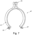
- Fig. 7 shows a further second line bracket 47 having a second support portion 21 and a second receiving space 19.
- the second receiving space 19 is designed in form of a snap-in connector, such that the second line section 6 is simply snappable into the second receiving space 19.
- the second support portion 21 exemplarily comprises a C-shape and can be snapped onto the first line section 4 and is securable through a cable tie or the like, which can be placed through two through-holes 37, comparable to the embodiment shown in Fig. 6 .
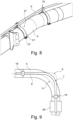
- Fig. 8 shows the second line bracket 47 clamped onto a first line section 4 and holding a second line section 6 in a three-dimensional view.
- Fig. 9 demonstrates an attachment of the second line section 6 on a bent first line section 4, which exemplarily constitutes a 90° elbow.
- the second line section 6 comprises an initial course 7, in which the second line section 6 has a sufficient reserve for a compression of the first line section 4.
- a resulting course of the second line section 6 is indicated by a dashed line 9.
- a sufficient reserve for a stretching of the first line section 4 is given, wherein a resulting course of the second line section 6 is indicated by a dashed line 11.
- fig. 10 shows an aircraft 48 having a fuselage 50 with at least one modular line assembly 2 arranged therein.
Landscapes
- Engineering & Computer Science (AREA)
- General Engineering & Computer Science (AREA)
- Mechanical Engineering (AREA)
- Aviation & Aerospace Engineering (AREA)
- Manufacturing & Machinery (AREA)
- Transportation (AREA)
- Mutual Connection Of Rods And Tubes (AREA)
- Supports For Pipes And Cables (AREA)
Abstract
Description
- The invention relates to a line assembly for installation in an aircraft fuselage, an aircraft as well as a method for installing a first line section and at least one second line section in an aircraft.
- In common commercial aircraft usually galley and sanitary equipment is installed. These require a potable water system for providing fresh water in a sufficient amount and quality. The potable water is commonly stored in a centralized water tank and is distributed via a pipe network. In conventional system architectures stainless steel or titanium pipes having a diameter between 0,5 inches and 0,75 inches are used. However, high and low pressure potable water pipes are known, which are based on flexible hoses from a plastic material, such as PEEK, wherein the high pressure hoses comprise an outer diameter of e.g. 6 mm. Furthermore, usually a vacuum toilet system is installed, based on a pneumatic transport system, which serves for the hygienic disposal of human waste. For this, the differential pressure between the cabin and outside air is used to convey waste through a titanium pipe, which may comprise a diameter of 2 inches, to a central waste tank. Still further, usually a waste-water system is installed, which is used to drain waste-water, e.g. from wash basins, via the heated drain masts overboard.
- Although potable water lines and pipework of the vacuum toilet system are laid in parallel between the water/waste storage tanks and the lavatory monuments, each of these sub-system installations is mounted separately to the aircraft structure with its own brackets. This results in a relatively high number of interface points to the aircraft structure. In case of customer-specific monument positions due to individual cabin layouts, each of these sub-systems needs to be adapted to the new location with a correspondingly high level of effort separately.
- Above-mentioned water supply hoses allow to reduce the installation effort, weight, and complexity. On the one hand, the elastic properties of such hoses are of high advantage for the installation process. On the other hand, they may require modified bracket distances instead of using conventional bracket distances, which are specified by the spacing between structural elements in the aircraft fuselage, e.g. frame or z-strut spacing. Overall, the common installation method induces high costs in terms of aircraft design and production due to the required installation and customization effort.
-
EP 3 385 163 A1 andUS 10,822,774 B2 - The object of the invention is to propose an improved installation for lines or similar system installations on board commercial aircraft to avoid at least some of the afore-mentioned constraints.
- The object is met by a line installation assembly having the features of independent claim 1. Advantageous embodiments and further improvements may be gathered from the subclaims and the following description.
- A modular line assembly for installation in an aircraft fuselage is proposed, the assembly comprising a first line section having a first diameter, at least one second line section having a second diameter, a set of first line brackets, and a set of second line brackets, wherein the first line brackets comprise a first receiving space designed for holding the first line section and a first support portion for attaching the first line brackets to a structural part of the fuselage, wherein the second line brackets comprise a second receiving space designed for holding the at least one second line section and a second support portion for attaching the second line brackets to the first line section, wherein at least one second line section comprises the same or higher flexibility than the first line section, and wherein the at least one second line section is attached to the first line section through a plurality of second line brackets that are arranged at a distance to and are independent from the first line brackets.
- The first line section comprises a first line for conveying a medium, such as air, a gas or gas mixture in general, water, waste-water, or waste. The first diameter may refer to an outer diameter of the first line section. For example, the first line section may refer to a vacuum line. Also, other pipes with a large diameter, e.g. waste-water piping, which are to be installed in the cabin and cargo area, can be used as a base element for the second line sections. This is in particular of advantage if there is no vacuum system interface present at a monument, as it is the case with galleys. The at least one second line section is independent from the first line section and comprises a second line for conveying a medium. The second line section may also be designed to convey a medium, wherein the medium in the second line section may differ from the medium in the first line section. For example, the second line section may refer to a potable water line.
- The first line section and the first line brackets are designed to conform each other, such that the first line brackets are capable of holding, e.g. enclosing or at least partially enclosing, the first line section for supporting the first line section on the fuselage. For this, the first line brackets each comprise a first receiving space that is designed to receive the first line section. Besides form-locking principles, i.e. positive fit connections, also non-positive fit connections, or material-bonding connections, such as gluing or welding, are possible. The first support portion is designed to be attachable to the respective structural component of the fuselage. Thus, by attaching the first line brackets to the structural component and holding the first line section by the first line brackets, the first line section is attached to the structural component.
- The first support portion is not to be considered a separate part. Instead, it may be a portion, i.e. a surface, a section or a dedicated region of the first line bracket that is somehow attached to a structure. If the first bracket is attached to the structure, there will be a portion of it interacting with the structure, be it a surface to bond to an adhesive, a positive or non-positive connection.
- It is preferred that a plurality of first line brackets holds the first line section. The first line brackets are arranged in a predetermined spacing along the fuselage, which may be determined by the spacing of stiffening components of the fuselage. For example, the first line brackets are attached to frame components, which are usually substantially circumferential profile parts defining a surface that is arranged normal to a longitudinal axis of the respective fuselage. The first line brackets may also be designed for an attachment to longitudinal stiffening elements, i.e. stringers or the like. However, other variants or combinations thereof are possible.
- A gist of the invention lies in providing the second line brackets, which are capable of holding the at least one second line section. The second support portions are, however, not designed to be attached to the structural part, but to the first line section. Thus, an assembly of a second line and a first line, which are connected to each other, may be provided. Here, the at least one second line section comprises a higher flexibility than the first line section. In the modular line assembly, the installation of first lines, e.g. vacuum lines, and second lines, e.g. potable water lines, are combined into one installation unit. In this installation unit the first line is attached to the aircraft structure as a base element in a known manner using standard bracketing in the form of the first line brackets. As an add-on element the second line is attached to the first line.
- At least one and preferably all of the first line brackets and the second line brackets may be made from a plastic material, depending on the size, and expected loads on the first and second line sections. It is conceivable that between two consecutive first line brackets, a plurality of second line brackets are placed. A group of a plurality of second line brackets may then be enclosed by two consecutive first line brackets. The first and/or second line brackets may be arranged in an equidistant manner, such that intermediate spaces between two first and/or second line brackets are equal.
- The modular line assembly according to the invention offers several advantages in comparison with known solutions. First of all, the number of required interface points between an aircraft structure and water system installations or other line arrangements can be drastically reduced. By creating a combined installation unit as mentioned above, only interfaces for the first line section with the aircraft structure need to be installed. Aircraft structural interfaces for the installation of the second line are nearly completely eliminated.
- Also, the efforts required to adapt a system to customer-defined monument positions are reduced. Since the second line, e.g. potable water line, may commonly be installed along the first line, e.g. lines of the vacuum toilet system, the routing results from this relationship and there is no need to plan the line routes separately. This clearly reduces the adaption effort for customer defined monument positions for a water/waste system or similar by around one half.
- Distances between brackets attached to the aircraft structure design are decoupled from the distances of two consecutive second line brackets, such that an arbitrary bracket spacing for water lines or other second line sections is enabled. Since there is no direct interface between the aircraft structure and the second line sections, the incremental design of the aircraft structure is no longer relevant for the distance between two brackets. Rather, nearly any bracket spacing can be achieved, since the first line section, e.g. a vacuum line, may be routed continuously between the waste tank and lavatory monuments. This corresponds to a complete decoupling process. The positioning of the second line brackets is only restricted by other elements which are installed to the first line section, such as first line brackets, bonding straps, or couplings. Buckling of the second hose section due to large unsupported lengths between two brackets and due to relative deformations in a longitudinal direction are avoided.
- The assembly allows to limit an unsupported pipe length to an acceptable value and thus simply avoids sagging or buckling effects of flexible second line sections. Water pockets residual water in gravity drained water systems can thus be avoided. The possibility of an arbitrary spacing of second line brackets for the installation of flexible second lines, e.g. water hoses, without the need for additional interfaces to the aircraft structure, offers the possibility of setting the unsupported pipe length between two second line brackets to an acceptable value, which is not critical in terms of sagging and buckling effects.
- Due to the freely selectable second line bracket spacing, vibration amplitudes can also be minimized. It is conceivable that the second line brackets may also comprise a spring-damper element, such that the transmission of vibrations to the first line section or the aircraft structure can be further reduced. Pressurization, or influences by the operation of the aircraft, e.g. wind milling, will not lead to a physical contact of the second line sections with neighboring systems/structures. Thus, disruptive noise or vibration effects leading can be avoided.
- Also, a pre-assembly of the modular line assembly is possible, for example in a triangle module underneath a cabin floor at a lateral region directly adjacent the fuselage wall. In particular, the modular line assembly according to the invention solves the above-identified object in that it eliminates the need for additional support structures or brackets mounted to the aircraft structure, system/structure interfaces or complex mounting brackets which would lead to disadvantages regarding weight, installation space and cost.
- A plurality of consecutively arranged first line sections may be coupled with each other through a coupling. It is conceivable that in the pipework of a vacuum toilet system, deformations relative to the aircraft structure are compensated through the couplings. It is preferred that the couplings are flexible. This allows a certain expansion or compression in longitudinal direction of the aircraft fuselage. Accordingly, the second line section, which is installed to a first line section in form of a vacuum pipe, also needs to provide such a deformability.
- For achieving this, the second line section may be installed in a non-straight manner. For example, the second line section may comprise at least one bend that allows expansion and compression movements. It is conceivable to provide bends in a periodical manner along the second line section. In this regard it is noted that the second line section or lines installed inside an aircraft should be as long as possible, i.e. in one piece, to reduce the installation effort for interface points and to prevent potential leaking points.
- As an alternative, compensation elements, similar to couplings of a vacuum line, may be installed. However, this would reduce the maximal length of the second line sections and may increase additional second line brackets. As stated further below, this may require at least one second line bracket to allow a movement of the respective second line section.
- At least one second line bracket may be arranged between two consecutive first line brackets. However, it is preferred that a plurality of second line brackets is arranged between two consecutive first line brackets. Since the second line section has a higher flexibility than the first line section it may be advantageous to install at least two or more second line brackets between two consecutive second line brackets, i.e. a higher number of second line brackets than first line brackets per length.
- However, providing at least one second line bracket between two consecutive first line brackets is not mandatory and mainly applies to straight sections of the first line section. It is possible to deviate from this for curved sections, pipe branches or the like and two first line brackets may follow one another, between which there is no second line bracket.
- The at least one second line section may comprise at least one bend. For example, the bend may be arranged in an overlapping region with one of the first line brackets and/or another component. Such an overlapping region is to be understood as a region where the respective second line section passes the respective first line bracket or component. The bend may also be placed in a region of a branch or a change of direction or pipe bend of the first line section. The term "another component" may refer to another system component, a coupling between consecutive first line sections, an elbow or branching of the first line section or other. The bend may be based on an overlength of the second line section, which leads to bending the second line section to change its orientation relative to the first line section. Exemplarily, a first line bracket or another component may thus be surrounded. By using the bend both line sections may be installed very close to each other. The bend also allows to compensate length variations due to temperature or pressure induced expansion or compression effects. The at least one bend is preferably elastic such that the second line section may expand, compress, and deform along the bend.
- For supporting the creation of the at least one bend, there may be second line brackets having a second receiving space that is slightly rotated, e.g. up to 15° or 30° in opposite directions in order to force the second line section, which should be flexible enough, into a bend.
- It is conceivable that the first diameter exceeds the second diameter. Thus, the first line section having the larger diameter is directly attachable to the structure and provides a rigid base for the second line section.
- The second line brackets may comprise a clamp that encloses the first line section in a plier-like manner. Such a clamp may thus surround the first line section at least partially, e.g. about at least 60%. By arresting the clamp in a state in which it encloses the first line section, the second line bracket is rigidly attached to the first line section. It may be feasible to completely surround the circumferential surface of the first line section by tightening the clamp on a side opposite to the second line section. For example, the clamp may be similar to a hose clamp.
- The second line brackets may comprise a stiction layer in direct contact with a surface of the first line section. The stiction layer increases the stick friction coefficient and may be based on a thin layer of a rubber-like material. It may be bonded to the second line bracket or to the first line section through an adhesive material, through an adhesive tape or the like. It is also conceivable that the stiction layer is a separate component that is simply embedded between the first line section and the second line bracket.
- The second line brackets may be designed for holding a plurality of second line sections. Thus, a plurality of second line sections are supportable by a single second line bracket, e.g. through a plurality of second receiving spaces integrated therein.
- It is advantageous if the second line brackets comprise at least one snap-in connector for holding the at least one second line section. The respective second line section may simply be advanced to the snap-in connector and pressed firmly onto it, such that the snap-in connector allows the second line segment to pass into the respective second receiving space to be held therein.
- Furthermore, the second receiving space and the second support portion may be provided in a base component and a top component, wherein the base component and top component are connectable to each other through a releasable connector. For example, both components may be connected through a click connector. The releasable connector may include a mechanism that securely latches upon pressing the base component and the top component onto each other. The connector may also comprise a release device, which is adapted for releasing the latched connection.
- As stated above, the first line section may comprise a vacuum pipe, and the at least one second line section may comprise at least one water hose. The vacuum pipe may be associated with a vacuum toilet system, while the water hose may be associated with a water consuming apparatus in a lavatory or galley monument.
- It is conceivable that the first line section is substantially rigid. Exemplarily, it may comprise a metal pipe, such as from titanium, aluminium, steel, stainless-steel, or other suitable, light-weight metal materials. However, a plastic material may also be suitable, in particular a fiber-reinforced plastic material. Still further, also any hybrid material comprising fractions of metal and plastic material is possible.
- At least one of the at least one second line bracket may allow a relative motion of the second line section along a main extension direction of the second line section. Thus, longitudinal expansion and compression movements of the at least one second line section relative to the first line section is allowed. In order to not have a completely moveable system, at least one second line bracket should be provided as a fixed bearings, if the fixed configuration is not already defined by a ramification of the second line sections, e.g. a water distribution network.
- It is further conceivable that at least one first line bracket is equippable with a top component mentioned above, such that the respective first line bracket is a hybrid bracket for accommodating a second line section in addition to the first line section.
- Furthermore, a second line bracket which is installed before or after a bend of the first line section may be provided with a cantilevering support structure that forces the respective second line section into the curvature of the bend, similar to a bridge. This may particularly be important if the second line section does not readily assume the course of a bend due to its rigidity.
- The invention also relates to an aircraft, comprising a fuselage having an interior space, and at least one modular line assembly according to the above description.
- The invention further relates to a method for installing a first line section and at least one second line section in a fuselage of an aircraft, comprising attaching a first line section having a first diameter to a structural part of the fuselage through first line brackets, which comprise a first receiving space designed for holding the first line section and a first support portion for attaching the first line brackets to the structural part, attaching at least one second line section having a second diameter to the first line section through second line brackets, which comprise a second receiving space designed for holding the at least one second line section and a second support portion for attaching the second line brackets to the first line section, wherein at least one second line section comprises the same or higher flexibility than the first line section, and wherein the at least one second line section is attached to the first line section through a plurality of second line brackets that are arranged at a distance to and are independent from the first line brackets.
- In the method, the second line brackets may be pre-installed to the first line section. However, it is conceivable that the second line brackets may be attached to the first line section after installation of the first line section.
- The method also supports a pre-assembly in a module. In a first step, the first line section, e.g. vacuum pipes, with their limited element lengths and provided with the second line brackets for the second line sections can be mounted on a module structure to be installed in the aircraft. In a second step, the more flexible second line sections, e.g. water hoses, can be installed along the first line sections without the need for installation-related coupling points. In the best case scenario, the second line sections are installed without tools, comparable to the installation of a cable. This may be achieved without the need for cost-intensive special parts. With the exception of the second line brackets between the first line sections and the second line sections, existing standard parts can be reused.
- It is also conceivable that the second line section comprises valves, sensors, fittings, e.g. elbows, t-pieces, couplings, or the like, which are also mounted on the first line section through dedicated brackets.
- In the following, the attached drawings are used to illustrate exemplary embodiments in more detail. The illustrations are schematic and not to scale. Identical reference numerals refer to identical or similar elements. They show:
- Fig. 1
- a modular line assembly in a sectional view,
- Fig. 2
- a modular line assembly in a three-dimensional view,
- Fig. 3 and 4
- bends in a line assembly,
- Fig. 5 to 7
- examples of second line brackets,
- Fig. 8
- a three-dimensional view with a first line section, a second line section and the second line brackets of
Fig. 8 , - Fig. 9
- a bend of a first line section, and
- Fig. 10
- an aircraft.
-
Fig. 1 shows amodular line assembly 2 in a sectional view for installation in an aircraft fuselage. Themodular line assembly 2 comprises afirst line section 4 having a first diameter D1, asecond line section 6 having a second diameter D2, afirst line bracket 8 and asecond line bracket 10. Thefirst line bracket 8 comprises afirst receiving space 12 designed for holding, and in this example enclosing, thefirst line section 4. Afirst support portion 14 is coupled with thefirst receiving space 12 and is designed for attaching thefirst line bracket 8 to astructural part 16 of the fuselage. It may comprise a spacer or damper or intermediate piece for increasing the contact surface with thestructural part 16. Here, thestructural part 16 is shown as a part of a cross-beam for support of a cabin floor. However, circumferential frames or z-struts or any other primary or secondary structure element is also possible. Thefirst line bracket 8 is designed as an Omega-shaped clamp, which firmly hold thefirst line section 4 on theframe 16. It is to be understood, that a plurality of first-line brackets 8 are used for holding thefirst line section 4. - The
second line bracket 10 comprises asecond receiving space 18 designed for holding, e.g. enclosing, thesecond line section 6 and asecond support portion 20 attaching thesecond line bracket 10 to thefirst line section 4. Thesecond line bracket 10 is shown in more detail in figures further below. - The
modular line assembly 2 allows to attach asecond line section 6 to thefirst line section 4, such that no further structural interfaces are required for holding thesecond line section 6 relative to thestructural part 16. This allows an improved flexibility in the placement of monuments and installing systems that are adapted to the individual requirements of an aircraft operator. -
Fig. 2 shows thefirst line section 4 in a three-dimensional view. It is held on thestructural part 16 by exemplarily threefirst line brackets 8. Thefirst line brackets 8 are spaced apart by a distance A, wherein it is advantageous to provide an equidistant arrangement of thefirst line brackets 8. Thesecond line section 6 is attached through a plurality ofsecond line brackets 10 to thefirst line section 4, wherein thesecond line brackets 10 are spaced apart by the distance B. Here, the distance B is clearly lower than the distance A, such that between two consecutive first-line brackets 8 a plurality ofsecond line brackets 10 are placed. In this example, fivesecond line brackets 10 are placed between two consecutive first-line brackets 8. - An overlapping
region 22 is created, where thesecond line section 6 passes afirst line bracket 8, a pipe coupling of thefirst line section 4, installations of other aircraft systems, other structural elements, or the like. In the overlappingregion 22, thesecond line section 6 may optionally comprise abend 24. Further examples of thebend 24 are further shown infig. 3 and 4 . -
Fig. 3 shows themodular line assembly 2, where thesecond line section 6 has abend 24 in an overlapping region with asystem component 26. Here, thesystem component 26 is avoided through thesecond line section 6 bypassing it in a sufficient distance to avoid damages to thesystem component 26 or thesecond line section 6. For this, thesecond line brackets 10 are adapted to comprise different distances to thefirst line section 4 or to provide different orientations to thefirst line section 4. For example, one of thesecond support portions 20 of thesecond line brackets 10 is adapted in its orientation, such that a respective local extension of thesecond line section 6, indicated with a dashed line, is arranged at an angle α to an extension of thefirst line section 4. Due to its flexibility, thesecond line section 20 provides a smooth curvature and thus forms thebend 24. - In
fig. 4 the overlappingregion 22 is created at acoupling 28 between two consecutivefirst line sections 4. Here, twoconsecutive support portions 18 are oriented in such a way that a local extension of thesecond line section 6 is arranged at an angle α relative to thefirst line section 4. Exemplarily, therespective support portions 18 are arranged in a mirror-inverted way. -
Fig. 5 shows thefirst line section 4 with thesecond line bracket 10 attached to it. Here, thesupport portion 20 is bonded to acircumferential surface 30 of thefirst line section 4 through an adhesive 32. In a distance to thesupport portion 20, thesecond receiving space 18 is provided to receive thesecond line section 6. Here, thesecond line section 6 is surrounded by a dampeninglayer 34. The receivingsection 18 exemplarily comprises acable tie 36 or another releasable fastening device to tighten thesecond line bracket 10 to thesecond line section 6. Thecoupling 28 fromfig. 4 is indicated with dashed lines. Exemplarily, thesecond line section 6 is arranged in a distance to thefirst line section 4 such that thesecond line section 6 is arranged outside the contour of thecoupling 28. -
Fig. 6 shows anothersecond line bracket 38, which exemplarily completely encloses thefirst line section 4 through abase component 39, which has a C-shape compatible with thefirst line section 4, such that it is snappable onto thefirst line section 4 and secured/tensioned by acable tie 40 arranged in two through-holes 37 at opposite ends of thebase component 39. Aclick connector 42 is provided to attach atop component 44 to thebase component 39. Thetop component 44 comprises a snap-inconnector 46 for receiving twosecond line sections 6. -
Fig. 7 shows a furthersecond line bracket 47 having asecond support portion 21 and asecond receiving space 19. Thesecond receiving space 19 is designed in form of a snap-in connector, such that thesecond line section 6 is simply snappable into thesecond receiving space 19. Thesecond support portion 21 exemplarily comprises a C-shape and can be snapped onto thefirst line section 4 and is securable through a cable tie or the like, which can be placed through two through-holes 37, comparable to the embodiment shown inFig. 6 . -
Fig. 8 shows thesecond line bracket 47 clamped onto afirst line section 4 and holding asecond line section 6 in a three-dimensional view. -
Fig. 9 demonstrates an attachment of thesecond line section 6 on a bentfirst line section 4, which exemplarily constitutes a 90° elbow. Here, thesecond line section 6 comprises aninitial course 7, in which thesecond line section 6 has a sufficient reserve for a compression of thefirst line section 4. A resulting course of thesecond line section 6 is indicated by a dashedline 9. Also, a sufficient reserve for a stretching of thefirst line section 4 is given, wherein a resulting course of thesecond line section 6 is indicated by a dashedline 11. - Furthermore,
fig. 10 shows anaircraft 48 having afuselage 50 with at least onemodular line assembly 2 arranged therein.
Claims (14)
- Modular line assembly (2) for installation in an aircraft fuselage (50), comprising:- a first line section (4) having a first diameter (D1),- at least one second line section (6) having a second diameter (D2),- a set of first line brackets (8), and- a set of second line brackets (10, 38, 47),wherein the first line brackets (8) comprise a first receiving space (12) designed for holding the first line section (4) and a first support portion (14) for attaching the first line brackets (8) to a structural part (16) of the fuselage (50),wherein the second line brackets (10, 38, 47) comprise a second receiving space (18, 19) designed for holding the at least one second line section (6) and a second support portion (20, 21) for attaching the second line brackets (10, 38, 47) to the first line section (4),wherein at least one second line section (6) comprises the same or higher flexibility than the first line section (4), andwherein the at least one second line section (6) is attached to the first line section (4) through a plurality of second line brackets (10, 38, 47) that are arranged at a distance to and are independent from the first line brackets (8).
- Modular line assembly (2) according to claim 1,
wherein at least one second line bracket (10, 38, 47) is arranged between two consecutive first line brackets (8). - Modular line assembly (2) according to claim 1 or 2,
wherein the at least one second line section (6) comprises at least one bend (24) in an overlapping region (22) with one of the first line brackets (8) and/or another component (26, 28). - Modular line assembly (2) according to any of the preceding claims,
wherein the first diameter (D1) exceeds the second diameter (D2). - Modular line assembly (2) according to any of the preceding claims,
wherein the second line brackets (10, 38, 47) comprise a clamp that encloses the first line section (4) in a plier-like manner. - Modular line assembly (2) according to claim 5,
wherein the second line brackets (10, 38, 47) comprise a stiction layer (41) in direct contact with a surface (30) of the first line section (4). - Modular line assembly (2) according to any of the preceding claims,
wherein the second line brackets (10, 38, 47) are designed for holding a plurality of second line sections. - Modular line assembly (2) according to any of the preceding claims,
wherein the second line brackets comprise at least one snap-in connector for holding the at least one second line section. - Modular line assembly (2) according to any of the preceding claims,wherein the second receiving space (18, 19) and the second support portion (20, 21) are provided in a base component (39) and a top component (44),wherein the base component (39) and top component (44) are connectable to each other through a releasable connector (42).
- Modular line assembly (2) according to any of the preceding claims,wherein the first line section (4) comprises a vacuum pipe, andwherein the at least one second line section (6) comprises at least one water hose.
- Modular line assembly (2) according to any of the preceding claims,
wherein the first line section (4) is substantially rigid. - Modular line assembly (2) according to any of the preceding claims,
wherein at least one of the at least one second line bracket (10) allows a relative motion of the second line section (6) along a main extension direction of the second line section (6). - Aircraft (48), comprising a fuselage (50) having an interior space, and at least one modular line assembly (2) according to any of the preceding claims.
- Method for installing a first line section (4) and at least one second line section (6) in a fuselage (50) of an aircraft (48), comprising:attaching a first line section (4) having a first diameter (D1) to a structural part (16) of the fuselage (50) through first line brackets (8), which comprise a first receiving space (12) designed for holding the first line section (4) and a first support portion (14) for attaching the first line brackets (8) to the structural part (16),attaching at least one second line section (6) having a second diameter (D2) to the first line section (4) through second line brackets (10, 38, 47), which comprise a second receiving space (18, 19) designed for holding the at least one second line section (6) and a second support portion (20, 21) for attaching the second line brackets (10, 38, 47) to the first line section (4),wherein at least one second line section (6) comprises a higher flexibility than the first line section (4), andwherein the at least one second line section (6) is attached to the first line section (4) through a plurality of second line brackets (10, 38, 47) that are arranged at a distance to and are independent from the first line brackets (8).
Priority Applications (5)
| Application Number | Priority Date | Filing Date | Title |
|---|---|---|---|
| EP21205381.3A EP4174352B1 (en) | 2021-10-28 | 2021-10-28 | Modular line assembly for installation in an aircraft fuselage |
| US17/973,832 US11878785B2 (en) | 2021-10-28 | 2022-10-26 | Modular line assembly for installation in an aircraft fuselage |
| EP22204135.2A EP4174353A1 (en) | 2021-10-28 | 2022-10-27 | Modular line assembly for installation in an aircraft fuselage |
| CN202211334569.2A CN116039927A (en) | 2021-10-28 | 2022-10-28 | Modular pipeline assembly for installation in aircraft fuselage |
| US18/526,601 US12195163B2 (en) | 2021-10-28 | 2023-12-01 | Modular line assembly for installation in an aircraft fuselage |
Applications Claiming Priority (1)
| Application Number | Priority Date | Filing Date | Title |
|---|---|---|---|
| EP21205381.3A EP4174352B1 (en) | 2021-10-28 | 2021-10-28 | Modular line assembly for installation in an aircraft fuselage |
Publications (2)
| Publication Number | Publication Date |
|---|---|
| EP4174352A1 true EP4174352A1 (en) | 2023-05-03 |
| EP4174352B1 EP4174352B1 (en) | 2026-05-06 |
Family
ID=78414425
Family Applications (2)
| Application Number | Title | Priority Date | Filing Date |
|---|---|---|---|
| EP21205381.3A Active EP4174352B1 (en) | 2021-10-28 | 2021-10-28 | Modular line assembly for installation in an aircraft fuselage |
| EP22204135.2A Pending EP4174353A1 (en) | 2021-10-28 | 2022-10-27 | Modular line assembly for installation in an aircraft fuselage |
Family Applications After (1)
| Application Number | Title | Priority Date | Filing Date |
|---|---|---|---|
| EP22204135.2A Pending EP4174353A1 (en) | 2021-10-28 | 2022-10-27 | Modular line assembly for installation in an aircraft fuselage |
Country Status (3)
| Country | Link |
|---|---|
| US (2) | US11878785B2 (en) |
| EP (2) | EP4174352B1 (en) |
| CN (1) | CN116039927A (en) |
Families Citing this family (1)
| Publication number | Priority date | Publication date | Assignee | Title |
|---|---|---|---|---|
| CN119429195B (en) * | 2024-11-12 | 2025-12-30 | 北京卫星环境工程研究所 | Rescue satellite hose compression release device |
Citations (5)
| Publication number | Priority date | Publication date | Assignee | Title |
|---|---|---|---|---|
| US4063315A (en) * | 1974-12-13 | 1977-12-20 | The Boeing Company | Vacuum toilet system |
| EP2499413A2 (en) * | 2009-11-12 | 2012-09-19 | E. I. du Pont de Nemours and Company | Clip for a pipe or duct |
| US20180277285A1 (en) * | 2017-03-21 | 2018-09-27 | Hubbell Incorporated | Non-conductive support stands |
| EP3385163A1 (en) | 2017-04-07 | 2018-10-10 | Airbus Operations GmbH | An aircraft comprising a high-pressure water supply and distribution system |
| US20200318671A1 (en) * | 2017-11-16 | 2020-10-08 | A. Raymond Et Cie | Fastener and use of a fastener |
Family Cites Families (2)
| Publication number | Priority date | Publication date | Assignee | Title |
|---|---|---|---|---|
| DE9306143U1 (en) | 1993-04-23 | 1993-07-29 | P.C. Turck GmbH & Co. KG, 5880 Lüdenscheid | Holding device for hoses and other cables |
| DE202007000256U1 (en) * | 2007-01-08 | 2007-03-08 | Wenko-Wenselaar Gmbh & Co. Kg | Clip for mounting on a cylindrical object comprises a ring element which encloses a cylindrical object in the mounted position on its periphery and axially lengthens a clip section in relation to the object |
-
2021
- 2021-10-28 EP EP21205381.3A patent/EP4174352B1/en active Active
-
2022
- 2022-10-26 US US17/973,832 patent/US11878785B2/en active Active
- 2022-10-27 EP EP22204135.2A patent/EP4174353A1/en active Pending
- 2022-10-28 CN CN202211334569.2A patent/CN116039927A/en active Pending
-
2023
- 2023-12-01 US US18/526,601 patent/US12195163B2/en active Active
Patent Citations (6)
| Publication number | Priority date | Publication date | Assignee | Title |
|---|---|---|---|---|
| US4063315A (en) * | 1974-12-13 | 1977-12-20 | The Boeing Company | Vacuum toilet system |
| EP2499413A2 (en) * | 2009-11-12 | 2012-09-19 | E. I. du Pont de Nemours and Company | Clip for a pipe or duct |
| US20180277285A1 (en) * | 2017-03-21 | 2018-09-27 | Hubbell Incorporated | Non-conductive support stands |
| EP3385163A1 (en) | 2017-04-07 | 2018-10-10 | Airbus Operations GmbH | An aircraft comprising a high-pressure water supply and distribution system |
| US10822774B2 (en) | 2017-04-07 | 2020-11-03 | Airbus Operations Gmbh | Aircraft comprising a high-pressure water supply and distribution system |
| US20200318671A1 (en) * | 2017-11-16 | 2020-10-08 | A. Raymond Et Cie | Fastener and use of a fastener |
Also Published As
| Publication number | Publication date |
|---|---|
| EP4174352B1 (en) | 2026-05-06 |
| US20240101243A1 (en) | 2024-03-28 |
| US12195163B2 (en) | 2025-01-14 |
| US11878785B2 (en) | 2024-01-23 |
| EP4174353A1 (en) | 2023-05-03 |
| US20230139167A1 (en) | 2023-05-04 |
| CN116039927A (en) | 2023-05-02 |
Similar Documents
| Publication | Publication Date | Title |
|---|---|---|
| RU2430855C2 (en) | Frame element, aircraft air conditioning system and method of mounting frame element in aircraft | |
| US6951324B2 (en) | Universal bracket for transporting an assembled conduit | |
| EP4174352B1 (en) | Modular line assembly for installation in an aircraft fuselage | |
| CN102458999B (en) | Transport device for use when mounting interior component modules in an aircraft | |
| US20110024565A1 (en) | Aircraft Component Assembly System | |
| US6116547A (en) | Modular tubing support and constrainment device | |
| US20130277901A1 (en) | Aircraft system component carrier system and mounting method | |
| US9758233B2 (en) | Support system having a crown integration panel (CIP) | |
| US20120015595A1 (en) | Aircraft ventilation system | |
| IL174322A (en) | Supporting collar | |
| EP3135585A1 (en) | Crown raceway support (crs) for crown integration panel (cip) | |
| US8459936B2 (en) | Flexible seal for gas turbine engine system | |
| JPH05503357A (en) | Preassembled air data sensors and transducers | |
| US20260125145A1 (en) | Modular line assembly for installation in an aircraft fuselage | |
| AU2002355766A1 (en) | A bending-restricting anchoring arrangement and an anchored flexible pipe structure | |
| EP1412665A1 (en) | A bending-restricting anchoring arrangement and an anchored flexible pipe structure | |
| EP2675703B1 (en) | Arrangement for passing a line in a load-free manner through a pressure frame of a fuselage of an aircraft or spacecraft | |
| WO2020249142A1 (en) | Optical cable protector for laying in small diameter pipes, the supporting system and the method of its laying. | |
| US20050036841A1 (en) | Apparatus and method for use in laying or recovering offshore pipelines or cables | |
| CN220134943U (en) | Thin-wall stainless steel pipe ripple compensator fixing structure | |
| CN218376448U (en) | Comprehensive supporting device for tunnel and comprehensive supporting system comprising same | |
| JPH1144382A (en) | Hanging device for displacement absorbing joint in piping facility | |
| EP3085620B1 (en) | Aircraft provided with a fluid tank module | |
| US11125030B2 (en) | Guiding system on a hybrid lifting tower, and hybrid lifting tower | |
| JP2008241120A (en) | Air-conditioning system comprising meandering suppressing-preventing mechanism of flexible duct, and meandering suppressing-preventing construction method of flexible duct |
Legal Events
| Date | Code | Title | Description |
|---|---|---|---|
| PUAI | Public reference made under article 153(3) epc to a published international application that has entered the european phase |
Free format text: ORIGINAL CODE: 0009012 |
|
| STAA | Information on the status of an ep patent application or granted ep patent |
Free format text: STATUS: THE APPLICATION HAS BEEN PUBLISHED |
|
| AK | Designated contracting states |
Kind code of ref document: A1 Designated state(s): AL AT BE BG CH CY CZ DE DK EE ES FI FR GB GR HR HU IE IS IT LI LT LU LV MC MK MT NL NO PL PT RO RS SE SI SK SM TR |
|
| STAA | Information on the status of an ep patent application or granted ep patent |
Free format text: STATUS: REQUEST FOR EXAMINATION WAS MADE |
|
| 17P | Request for examination filed |
Effective date: 20231031 |
|
| RBV | Designated contracting states (corrected) |
Designated state(s): AL AT BE BG CH CY CZ DE DK EE ES FI FR GB GR HR HU IE IS IT LI LT LU LV MC MK MT NL NO PL PT RO RS SE SI SK SM TR |
|
| STAA | Information on the status of an ep patent application or granted ep patent |
Free format text: STATUS: EXAMINATION IS IN PROGRESS |
|
| 17Q | First examination report despatched |
Effective date: 20241104 |
|
| GRAP | Despatch of communication of intention to grant a patent |
Free format text: ORIGINAL CODE: EPIDOSNIGR1 |
|
| STAA | Information on the status of an ep patent application or granted ep patent |
Free format text: STATUS: GRANT OF PATENT IS INTENDED |
|
| INTG | Intention to grant announced |
Effective date: 20260204 |
|
| GRAS | Grant fee paid |
Free format text: ORIGINAL CODE: EPIDOSNIGR3 |
|
| GRAA | (expected) grant |
Free format text: ORIGINAL CODE: 0009210 |
|
| STAA | Information on the status of an ep patent application or granted ep patent |
Free format text: STATUS: THE PATENT HAS BEEN GRANTED |
|
| AK | Designated contracting states |
Kind code of ref document: B1 Designated state(s): AL AT BE BG CH CY CZ DE DK EE ES FI FR GB GR HR HU IE IS IT LI LT LU LV MC MK MT NL NO PL PT RO RS SE SI SK SM TR |
|
| REG | Reference to a national code |
Ref country code: CH Ref legal event code: F10 Free format text: ST27 STATUS EVENT CODE: U-0-0-F10-F00 (AS PROVIDED BY THE NATIONAL OFFICE) Effective date: 20260506 Ref country code: GB Ref legal event code: FG4D |