EP4174325A1 - System and method for controlling hydraulic valve operation within a work vehicle - Google Patents
System and method for controlling hydraulic valve operation within a work vehicle Download PDFInfo
- Publication number
- EP4174325A1 EP4174325A1 EP22203395.3A EP22203395A EP4174325A1 EP 4174325 A1 EP4174325 A1 EP 4174325A1 EP 22203395 A EP22203395 A EP 22203395A EP 4174325 A1 EP4174325 A1 EP 4174325A1
- Authority
- EP
- European Patent Office
- Prior art keywords
- hydraulic
- pressure
- flow control
- control valve
- computing system
- Prior art date
- Legal status (The legal status is an assumption and is not a legal conclusion. Google has not performed a legal analysis and makes no representation as to the accuracy of the status listed.)
- Pending
Links
Images

Classifications
-
- F—MECHANICAL ENGINEERING; LIGHTING; HEATING; WEAPONS; BLASTING
- F15—FLUID-PRESSURE ACTUATORS; HYDRAULICS OR PNEUMATICS IN GENERAL
- F15B—SYSTEMS ACTING BY MEANS OF FLUIDS IN GENERAL; FLUID-PRESSURE ACTUATORS, e.g. SERVOMOTORS; DETAILS OF FLUID-PRESSURE SYSTEMS, NOT OTHERWISE PROVIDED FOR
- F15B11/00—Servomotor systems without provision for follow-up action ; Circuits therefor
- F15B11/16—Servomotor systems without provision for follow-up action ; Circuits therefor with two or more servomotors
- F15B11/161—Servomotor systems without provision for follow-up action ; Circuits therefor with two or more servomotors with sensing of servomotor demand or load
-
- E—FIXED CONSTRUCTIONS
- E02—HYDRAULIC ENGINEERING; FOUNDATIONS; SOIL SHIFTING
- E02F—DREDGING; SOIL-SHIFTING
- E02F9/00—Component parts of dredgers or soil-shifting machines, not restricted to one of the kinds covered by groups E02F3/00 - E02F7/00
- E02F9/20—Drives; Control devices
- E02F9/22—Hydraulic or pneumatic drives
- E02F9/2221—Control of flow rate; Load sensing arrangements
- E02F9/2225—Control of flow rate; Load sensing arrangements using pressure-compensating valves
- E02F9/2228—Control of flow rate; Load sensing arrangements using pressure-compensating valves including an electronic controller
-
- E—FIXED CONSTRUCTIONS
- E02—HYDRAULIC ENGINEERING; FOUNDATIONS; SOIL SHIFTING
- E02F—DREDGING; SOIL-SHIFTING
- E02F9/00—Component parts of dredgers or soil-shifting machines, not restricted to one of the kinds covered by groups E02F3/00 - E02F7/00
- E02F9/20—Drives; Control devices
- E02F9/22—Hydraulic or pneumatic drives
- E02F9/2221—Control of flow rate; Load sensing arrangements
- E02F9/2232—Control of flow rate; Load sensing arrangements using one or more variable displacement pumps
- E02F9/2235—Control of flow rate; Load sensing arrangements using one or more variable displacement pumps including an electronic controller
-
- E—FIXED CONSTRUCTIONS
- E02—HYDRAULIC ENGINEERING; FOUNDATIONS; SOIL SHIFTING
- E02F—DREDGING; SOIL-SHIFTING
- E02F9/00—Component parts of dredgers or soil-shifting machines, not restricted to one of the kinds covered by groups E02F3/00 - E02F7/00
- E02F9/20—Drives; Control devices
- E02F9/22—Hydraulic or pneumatic drives
- E02F9/2264—Arrangements or adaptations of elements for hydraulic drives
- E02F9/2267—Valves or distributors
-
- E—FIXED CONSTRUCTIONS
- E02—HYDRAULIC ENGINEERING; FOUNDATIONS; SOIL SHIFTING
- E02F—DREDGING; SOIL-SHIFTING
- E02F9/00—Component parts of dredgers or soil-shifting machines, not restricted to one of the kinds covered by groups E02F3/00 - E02F7/00
- E02F9/20—Drives; Control devices
- E02F9/22—Hydraulic or pneumatic drives
- E02F9/2278—Hydraulic circuits
- E02F9/2296—Systems with a variable displacement pump
-
- F—MECHANICAL ENGINEERING; LIGHTING; HEATING; WEAPONS; BLASTING
- F15—FLUID-PRESSURE ACTUATORS; HYDRAULICS OR PNEUMATICS IN GENERAL
- F15B—SYSTEMS ACTING BY MEANS OF FLUIDS IN GENERAL; FLUID-PRESSURE ACTUATORS, e.g. SERVOMOTORS; DETAILS OF FLUID-PRESSURE SYSTEMS, NOT OTHERWISE PROVIDED FOR
- F15B11/00—Servomotor systems without provision for follow-up action ; Circuits therefor
- F15B11/16—Servomotor systems without provision for follow-up action ; Circuits therefor with two or more servomotors
- F15B11/161—Servomotor systems without provision for follow-up action ; Circuits therefor with two or more servomotors with sensing of servomotor demand or load
- F15B11/163—Servomotor systems without provision for follow-up action ; Circuits therefor with two or more servomotors with sensing of servomotor demand or load for sharing the pump output equally amongst users or groups of users, e.g. using anti-saturation, pressure compensation
-
- F—MECHANICAL ENGINEERING; LIGHTING; HEATING; WEAPONS; BLASTING
- F15—FLUID-PRESSURE ACTUATORS; HYDRAULICS OR PNEUMATICS IN GENERAL
- F15B—SYSTEMS ACTING BY MEANS OF FLUIDS IN GENERAL; FLUID-PRESSURE ACTUATORS, e.g. SERVOMOTORS; DETAILS OF FLUID-PRESSURE SYSTEMS, NOT OTHERWISE PROVIDED FOR
- F15B11/00—Servomotor systems without provision for follow-up action ; Circuits therefor
- F15B11/16—Servomotor systems without provision for follow-up action ; Circuits therefor with two or more servomotors
- F15B11/161—Servomotor systems without provision for follow-up action ; Circuits therefor with two or more servomotors with sensing of servomotor demand or load
- F15B11/165—Servomotor systems without provision for follow-up action ; Circuits therefor with two or more servomotors with sensing of servomotor demand or load for adjusting the pump output or bypass in response to demand
-
- F—MECHANICAL ENGINEERING; LIGHTING; HEATING; WEAPONS; BLASTING
- F15—FLUID-PRESSURE ACTUATORS; HYDRAULICS OR PNEUMATICS IN GENERAL
- F15B—SYSTEMS ACTING BY MEANS OF FLUIDS IN GENERAL; FLUID-PRESSURE ACTUATORS, e.g. SERVOMOTORS; DETAILS OF FLUID-PRESSURE SYSTEMS, NOT OTHERWISE PROVIDED FOR
- F15B21/00—Common features of fluid actuator systems; Fluid-pressure actuator systems or details thereof, not covered by any other group of this subclass
- F15B21/08—Servomotor systems incorporating electrically operated control means
- F15B21/087—Control strategy, e.g. with block diagram
-
- F—MECHANICAL ENGINEERING; LIGHTING; HEATING; WEAPONS; BLASTING
- F15—FLUID-PRESSURE ACTUATORS; HYDRAULICS OR PNEUMATICS IN GENERAL
- F15B—SYSTEMS ACTING BY MEANS OF FLUIDS IN GENERAL; FLUID-PRESSURE ACTUATORS, e.g. SERVOMOTORS; DETAILS OF FLUID-PRESSURE SYSTEMS, NOT OTHERWISE PROVIDED FOR
- F15B21/00—Common features of fluid actuator systems; Fluid-pressure actuator systems or details thereof, not covered by any other group of this subclass
- F15B21/08—Servomotor systems incorporating electrically operated control means
- F15B21/085—Servomotor systems incorporating electrically operated control means using a data bus, e.g. "CANBUS"
-
- F—MECHANICAL ENGINEERING; LIGHTING; HEATING; WEAPONS; BLASTING
- F15—FLUID-PRESSURE ACTUATORS; HYDRAULICS OR PNEUMATICS IN GENERAL
- F15B—SYSTEMS ACTING BY MEANS OF FLUIDS IN GENERAL; FLUID-PRESSURE ACTUATORS, e.g. SERVOMOTORS; DETAILS OF FLUID-PRESSURE SYSTEMS, NOT OTHERWISE PROVIDED FOR
- F15B2211/00—Circuits for servomotor systems
- F15B2211/20—Fluid pressure source, e.g. accumulator or variable axial piston pump
- F15B2211/205—Systems with pumps
- F15B2211/2053—Type of pump
- F15B2211/20546—Type of pump variable capacity
- F15B2211/20553—Type of pump variable capacity with pilot circuit, e.g. for controlling a swash plate
-
- F—MECHANICAL ENGINEERING; LIGHTING; HEATING; WEAPONS; BLASTING
- F15—FLUID-PRESSURE ACTUATORS; HYDRAULICS OR PNEUMATICS IN GENERAL
- F15B—SYSTEMS ACTING BY MEANS OF FLUIDS IN GENERAL; FLUID-PRESSURE ACTUATORS, e.g. SERVOMOTORS; DETAILS OF FLUID-PRESSURE SYSTEMS, NOT OTHERWISE PROVIDED FOR
- F15B2211/00—Circuits for servomotor systems
- F15B2211/20—Fluid pressure source, e.g. accumulator or variable axial piston pump
- F15B2211/25—Pressure control functions
- F15B2211/253—Pressure margin control, e.g. pump pressure in relation to load pressure
-
- F—MECHANICAL ENGINEERING; LIGHTING; HEATING; WEAPONS; BLASTING
- F15—FLUID-PRESSURE ACTUATORS; HYDRAULICS OR PNEUMATICS IN GENERAL
- F15B—SYSTEMS ACTING BY MEANS OF FLUIDS IN GENERAL; FLUID-PRESSURE ACTUATORS, e.g. SERVOMOTORS; DETAILS OF FLUID-PRESSURE SYSTEMS, NOT OTHERWISE PROVIDED FOR
- F15B2211/00—Circuits for servomotor systems
- F15B2211/30—Directional control
- F15B2211/305—Directional control characterised by the type of valves
- F15B2211/30525—Directional control valves, e.g. 4/3-directional control valve
-
- F—MECHANICAL ENGINEERING; LIGHTING; HEATING; WEAPONS; BLASTING
- F15—FLUID-PRESSURE ACTUATORS; HYDRAULICS OR PNEUMATICS IN GENERAL
- F15B—SYSTEMS ACTING BY MEANS OF FLUIDS IN GENERAL; FLUID-PRESSURE ACTUATORS, e.g. SERVOMOTORS; DETAILS OF FLUID-PRESSURE SYSTEMS, NOT OTHERWISE PROVIDED FOR
- F15B2211/00—Circuits for servomotor systems
- F15B2211/30—Directional control
- F15B2211/305—Directional control characterised by the type of valves
- F15B2211/30525—Directional control valves, e.g. 4/3-directional control valve
- F15B2211/3053—In combination with a pressure compensating valve
- F15B2211/3055—In combination with a pressure compensating valve the pressure compensating valve is arranged between directional control valve and return line
-
- F—MECHANICAL ENGINEERING; LIGHTING; HEATING; WEAPONS; BLASTING
- F15—FLUID-PRESSURE ACTUATORS; HYDRAULICS OR PNEUMATICS IN GENERAL
- F15B—SYSTEMS ACTING BY MEANS OF FLUIDS IN GENERAL; FLUID-PRESSURE ACTUATORS, e.g. SERVOMOTORS; DETAILS OF FLUID-PRESSURE SYSTEMS, NOT OTHERWISE PROVIDED FOR
- F15B2211/00—Circuits for servomotor systems
- F15B2211/30—Directional control
- F15B2211/31—Directional control characterised by the positions of the valve element
- F15B2211/3144—Directional control characterised by the positions of the valve element the positions being continuously variable, e.g. as realised by proportional valves
-
- F—MECHANICAL ENGINEERING; LIGHTING; HEATING; WEAPONS; BLASTING
- F15—FLUID-PRESSURE ACTUATORS; HYDRAULICS OR PNEUMATICS IN GENERAL
- F15B—SYSTEMS ACTING BY MEANS OF FLUIDS IN GENERAL; FLUID-PRESSURE ACTUATORS, e.g. SERVOMOTORS; DETAILS OF FLUID-PRESSURE SYSTEMS, NOT OTHERWISE PROVIDED FOR
- F15B2211/00—Circuits for servomotor systems
- F15B2211/30—Directional control
- F15B2211/315—Directional control characterised by the connections of the valve or valves in the circuit
- F15B2211/31523—Directional control characterised by the connections of the valve or valves in the circuit being connected to a pressure source and an output member
- F15B2211/31529—Directional control characterised by the connections of the valve or valves in the circuit being connected to a pressure source and an output member having a single pressure source and a single output member
-
- F—MECHANICAL ENGINEERING; LIGHTING; HEATING; WEAPONS; BLASTING
- F15—FLUID-PRESSURE ACTUATORS; HYDRAULICS OR PNEUMATICS IN GENERAL
- F15B—SYSTEMS ACTING BY MEANS OF FLUIDS IN GENERAL; FLUID-PRESSURE ACTUATORS, e.g. SERVOMOTORS; DETAILS OF FLUID-PRESSURE SYSTEMS, NOT OTHERWISE PROVIDED FOR
- F15B2211/00—Circuits for servomotor systems
- F15B2211/30—Directional control
- F15B2211/315—Directional control characterised by the connections of the valve or valves in the circuit
- F15B2211/3157—Directional control characterised by the connections of the valve or valves in the circuit being connected to a pressure source, an output member and a return line
- F15B2211/31576—Directional control characterised by the connections of the valve or valves in the circuit being connected to a pressure source, an output member and a return line having a single pressure source and a single output member
-
- F—MECHANICAL ENGINEERING; LIGHTING; HEATING; WEAPONS; BLASTING
- F15—FLUID-PRESSURE ACTUATORS; HYDRAULICS OR PNEUMATICS IN GENERAL
- F15B—SYSTEMS ACTING BY MEANS OF FLUIDS IN GENERAL; FLUID-PRESSURE ACTUATORS, e.g. SERVOMOTORS; DETAILS OF FLUID-PRESSURE SYSTEMS, NOT OTHERWISE PROVIDED FOR
- F15B2211/00—Circuits for servomotor systems
- F15B2211/30—Directional control
- F15B2211/32—Directional control characterised by the type of actuation
- F15B2211/327—Directional control characterised by the type of actuation electrically or electronically
-
- F—MECHANICAL ENGINEERING; LIGHTING; HEATING; WEAPONS; BLASTING
- F15—FLUID-PRESSURE ACTUATORS; HYDRAULICS OR PNEUMATICS IN GENERAL
- F15B—SYSTEMS ACTING BY MEANS OF FLUIDS IN GENERAL; FLUID-PRESSURE ACTUATORS, e.g. SERVOMOTORS; DETAILS OF FLUID-PRESSURE SYSTEMS, NOT OTHERWISE PROVIDED FOR
- F15B2211/00—Circuits for servomotor systems
- F15B2211/30—Directional control
- F15B2211/35—Directional control combined with flow control
- F15B2211/351—Flow control by regulating means in feed line, i.e. meter-in control
-
- F—MECHANICAL ENGINEERING; LIGHTING; HEATING; WEAPONS; BLASTING
- F15—FLUID-PRESSURE ACTUATORS; HYDRAULICS OR PNEUMATICS IN GENERAL
- F15B—SYSTEMS ACTING BY MEANS OF FLUIDS IN GENERAL; FLUID-PRESSURE ACTUATORS, e.g. SERVOMOTORS; DETAILS OF FLUID-PRESSURE SYSTEMS, NOT OTHERWISE PROVIDED FOR
- F15B2211/00—Circuits for servomotor systems
- F15B2211/40—Flow control
- F15B2211/405—Flow control characterised by the type of flow control means or valve
- F15B2211/40515—Flow control characterised by the type of flow control means or valve with variable throttles or orifices
-
- F—MECHANICAL ENGINEERING; LIGHTING; HEATING; WEAPONS; BLASTING
- F15—FLUID-PRESSURE ACTUATORS; HYDRAULICS OR PNEUMATICS IN GENERAL
- F15B—SYSTEMS ACTING BY MEANS OF FLUIDS IN GENERAL; FLUID-PRESSURE ACTUATORS, e.g. SERVOMOTORS; DETAILS OF FLUID-PRESSURE SYSTEMS, NOT OTHERWISE PROVIDED FOR
- F15B2211/00—Circuits for servomotor systems
- F15B2211/40—Flow control
- F15B2211/42—Flow control characterised by the type of actuation
- F15B2211/426—Flow control characterised by the type of actuation electrically or electronically
-
- F—MECHANICAL ENGINEERING; LIGHTING; HEATING; WEAPONS; BLASTING
- F15—FLUID-PRESSURE ACTUATORS; HYDRAULICS OR PNEUMATICS IN GENERAL
- F15B—SYSTEMS ACTING BY MEANS OF FLUIDS IN GENERAL; FLUID-PRESSURE ACTUATORS, e.g. SERVOMOTORS; DETAILS OF FLUID-PRESSURE SYSTEMS, NOT OTHERWISE PROVIDED FOR
- F15B2211/00—Circuits for servomotor systems
- F15B2211/40—Flow control
- F15B2211/455—Control of flow in the feed line, i.e. meter-in control
-
- F—MECHANICAL ENGINEERING; LIGHTING; HEATING; WEAPONS; BLASTING
- F15—FLUID-PRESSURE ACTUATORS; HYDRAULICS OR PNEUMATICS IN GENERAL
- F15B—SYSTEMS ACTING BY MEANS OF FLUIDS IN GENERAL; FLUID-PRESSURE ACTUATORS, e.g. SERVOMOTORS; DETAILS OF FLUID-PRESSURE SYSTEMS, NOT OTHERWISE PROVIDED FOR
- F15B2211/00—Circuits for servomotor systems
- F15B2211/50—Pressure control
- F15B2211/505—Pressure control characterised by the type of pressure control means
- F15B2211/50554—Pressure control characterised by the type of pressure control means the pressure control means controlling a pressure downstream of the pressure control means, e.g. pressure reducing valve
-
- F—MECHANICAL ENGINEERING; LIGHTING; HEATING; WEAPONS; BLASTING
- F15—FLUID-PRESSURE ACTUATORS; HYDRAULICS OR PNEUMATICS IN GENERAL
- F15B—SYSTEMS ACTING BY MEANS OF FLUIDS IN GENERAL; FLUID-PRESSURE ACTUATORS, e.g. SERVOMOTORS; DETAILS OF FLUID-PRESSURE SYSTEMS, NOT OTHERWISE PROVIDED FOR
- F15B2211/00—Circuits for servomotor systems
- F15B2211/50—Pressure control
- F15B2211/51—Pressure control characterised by the positions of the valve element
- F15B2211/513—Pressure control characterised by the positions of the valve element the positions being continuously variable, e.g. as realised by proportional valves
-
- F—MECHANICAL ENGINEERING; LIGHTING; HEATING; WEAPONS; BLASTING
- F15—FLUID-PRESSURE ACTUATORS; HYDRAULICS OR PNEUMATICS IN GENERAL
- F15B—SYSTEMS ACTING BY MEANS OF FLUIDS IN GENERAL; FLUID-PRESSURE ACTUATORS, e.g. SERVOMOTORS; DETAILS OF FLUID-PRESSURE SYSTEMS, NOT OTHERWISE PROVIDED FOR
- F15B2211/00—Circuits for servomotor systems
- F15B2211/50—Pressure control
- F15B2211/52—Pressure control characterised by the type of actuation
- F15B2211/526—Pressure control characterised by the type of actuation electrically or electronically
-
- F—MECHANICAL ENGINEERING; LIGHTING; HEATING; WEAPONS; BLASTING
- F15—FLUID-PRESSURE ACTUATORS; HYDRAULICS OR PNEUMATICS IN GENERAL
- F15B—SYSTEMS ACTING BY MEANS OF FLUIDS IN GENERAL; FLUID-PRESSURE ACTUATORS, e.g. SERVOMOTORS; DETAILS OF FLUID-PRESSURE SYSTEMS, NOT OTHERWISE PROVIDED FOR
- F15B2211/00—Circuits for servomotor systems
- F15B2211/50—Pressure control
- F15B2211/565—Control of a downstream pressure
-
- F—MECHANICAL ENGINEERING; LIGHTING; HEATING; WEAPONS; BLASTING
- F15—FLUID-PRESSURE ACTUATORS; HYDRAULICS OR PNEUMATICS IN GENERAL
- F15B—SYSTEMS ACTING BY MEANS OF FLUIDS IN GENERAL; FLUID-PRESSURE ACTUATORS, e.g. SERVOMOTORS; DETAILS OF FLUID-PRESSURE SYSTEMS, NOT OTHERWISE PROVIDED FOR
- F15B2211/00—Circuits for servomotor systems
- F15B2211/60—Circuit components or control therefor
- F15B2211/63—Electronic controllers
- F15B2211/6303—Electronic controllers using input signals
- F15B2211/6306—Electronic controllers using input signals representing a pressure
- F15B2211/6309—Electronic controllers using input signals representing a pressure the pressure being a pressure source supply pressure
-
- F—MECHANICAL ENGINEERING; LIGHTING; HEATING; WEAPONS; BLASTING
- F15—FLUID-PRESSURE ACTUATORS; HYDRAULICS OR PNEUMATICS IN GENERAL
- F15B—SYSTEMS ACTING BY MEANS OF FLUIDS IN GENERAL; FLUID-PRESSURE ACTUATORS, e.g. SERVOMOTORS; DETAILS OF FLUID-PRESSURE SYSTEMS, NOT OTHERWISE PROVIDED FOR
- F15B2211/00—Circuits for servomotor systems
- F15B2211/60—Circuit components or control therefor
- F15B2211/63—Electronic controllers
- F15B2211/6303—Electronic controllers using input signals
- F15B2211/6306—Electronic controllers using input signals representing a pressure
- F15B2211/6313—Electronic controllers using input signals representing a pressure the pressure being a load pressure
-
- F—MECHANICAL ENGINEERING; LIGHTING; HEATING; WEAPONS; BLASTING
- F15—FLUID-PRESSURE ACTUATORS; HYDRAULICS OR PNEUMATICS IN GENERAL
- F15B—SYSTEMS ACTING BY MEANS OF FLUIDS IN GENERAL; FLUID-PRESSURE ACTUATORS, e.g. SERVOMOTORS; DETAILS OF FLUID-PRESSURE SYSTEMS, NOT OTHERWISE PROVIDED FOR
- F15B2211/00—Circuits for servomotor systems
- F15B2211/60—Circuit components or control therefor
- F15B2211/63—Electronic controllers
- F15B2211/6303—Electronic controllers using input signals
- F15B2211/6346—Electronic controllers using input signals representing a state of input means, e.g. joystick position
-
- F—MECHANICAL ENGINEERING; LIGHTING; HEATING; WEAPONS; BLASTING
- F15—FLUID-PRESSURE ACTUATORS; HYDRAULICS OR PNEUMATICS IN GENERAL
- F15B—SYSTEMS ACTING BY MEANS OF FLUIDS IN GENERAL; FLUID-PRESSURE ACTUATORS, e.g. SERVOMOTORS; DETAILS OF FLUID-PRESSURE SYSTEMS, NOT OTHERWISE PROVIDED FOR
- F15B2211/00—Circuits for servomotor systems
- F15B2211/60—Circuit components or control therefor
- F15B2211/665—Methods of control using electronic components
- F15B2211/6654—Flow rate control
-
- F—MECHANICAL ENGINEERING; LIGHTING; HEATING; WEAPONS; BLASTING
- F15—FLUID-PRESSURE ACTUATORS; HYDRAULICS OR PNEUMATICS IN GENERAL
- F15B—SYSTEMS ACTING BY MEANS OF FLUIDS IN GENERAL; FLUID-PRESSURE ACTUATORS, e.g. SERVOMOTORS; DETAILS OF FLUID-PRESSURE SYSTEMS, NOT OTHERWISE PROVIDED FOR
- F15B2211/00—Circuits for servomotor systems
- F15B2211/60—Circuit components or control therefor
- F15B2211/665—Methods of control using electronic components
- F15B2211/6655—Power control, e.g. combined pressure and flow rate control
-
- F—MECHANICAL ENGINEERING; LIGHTING; HEATING; WEAPONS; BLASTING
- F15—FLUID-PRESSURE ACTUATORS; HYDRAULICS OR PNEUMATICS IN GENERAL
- F15B—SYSTEMS ACTING BY MEANS OF FLUIDS IN GENERAL; FLUID-PRESSURE ACTUATORS, e.g. SERVOMOTORS; DETAILS OF FLUID-PRESSURE SYSTEMS, NOT OTHERWISE PROVIDED FOR
- F15B2211/00—Circuits for servomotor systems
- F15B2211/70—Output members, e.g. hydraulic motors or cylinders or control therefor
- F15B2211/71—Multiple output members, e.g. multiple hydraulic motors or cylinders
-
- F—MECHANICAL ENGINEERING; LIGHTING; HEATING; WEAPONS; BLASTING
- F15—FLUID-PRESSURE ACTUATORS; HYDRAULICS OR PNEUMATICS IN GENERAL
- F15B—SYSTEMS ACTING BY MEANS OF FLUIDS IN GENERAL; FLUID-PRESSURE ACTUATORS, e.g. SERVOMOTORS; DETAILS OF FLUID-PRESSURE SYSTEMS, NOT OTHERWISE PROVIDED FOR
- F15B2211/00—Circuits for servomotor systems
- F15B2211/70—Output members, e.g. hydraulic motors or cylinders or control therefor
- F15B2211/71—Multiple output members, e.g. multiple hydraulic motors or cylinders
- F15B2211/7135—Combinations of output members of different types, e.g. single-acting cylinders with rotary motors
-
- F—MECHANICAL ENGINEERING; LIGHTING; HEATING; WEAPONS; BLASTING
- F15—FLUID-PRESSURE ACTUATORS; HYDRAULICS OR PNEUMATICS IN GENERAL
- F15B—SYSTEMS ACTING BY MEANS OF FLUIDS IN GENERAL; FLUID-PRESSURE ACTUATORS, e.g. SERVOMOTORS; DETAILS OF FLUID-PRESSURE SYSTEMS, NOT OTHERWISE PROVIDED FOR
- F15B2211/00—Circuits for servomotor systems
- F15B2211/70—Output members, e.g. hydraulic motors or cylinders or control therefor
- F15B2211/71—Multiple output members, e.g. multiple hydraulic motors or cylinders
- F15B2211/7142—Multiple output members, e.g. multiple hydraulic motors or cylinders the output members being arranged in multiple groups
-
- F—MECHANICAL ENGINEERING; LIGHTING; HEATING; WEAPONS; BLASTING
- F15—FLUID-PRESSURE ACTUATORS; HYDRAULICS OR PNEUMATICS IN GENERAL
- F15B—SYSTEMS ACTING BY MEANS OF FLUIDS IN GENERAL; FLUID-PRESSURE ACTUATORS, e.g. SERVOMOTORS; DETAILS OF FLUID-PRESSURE SYSTEMS, NOT OTHERWISE PROVIDED FOR
- F15B2211/00—Circuits for servomotor systems
- F15B2211/70—Output members, e.g. hydraulic motors or cylinders or control therefor
- F15B2211/78—Control of multiple output members
Definitions
- the present disclosure generally relates to work vehicles and, more particularly, to systems and methods for controlling the operation of hydraulic valves within a work vehicle.
- a work vehicle such as a construction vehicle, an agricultural vehicle, or the like, generally includes a hydraulic system to actuate various components of the vehicle.
- the hydraulic system may to raise and lower an implement, such as a bucket, at the operator's command.
- the hydraulic system generally includes one or more hydraulic loads (e.g., hydraulic actuators, motors, and/or the like) and a pump configured to supply hydraulic fluid to the load(s)
- the hydraulic system may include various valves and other flow control devices to control the flow of the hydraulic fluid from the pump to the hydraulic load(s).
- many hydraulic systems include a flow control valve having an adjustable orifice positioned upstream of each hydraulic load that controls the flow rate of the hydraulic fluid being delivered to the corresponding load(s).
- each flow control valve controls the flow rate of the hydraulic fluid being supplied to the downstream load(s) based on the opening position or cross-sectional area of its orifice.
- many hydraulic systems include a compensator valve positioned adjacent to each flow control valve.
- the compensator valve maintains a predetermined pressure drop across the corresponding flow control valve regardless of the opening position of its orifice.
- the compensator valve creates a greater than necessary pressure drop across the corresponding flow control valve. This results in a greater load on the pump, thereby increasing the energy consumption of the work vehicle and reducing its fuel economy.
- an improved system and method for controlling hydraulic valve operation within a work vehicle would be welcomed in the technology.
- an improved system and method for controlling hydraulic valve operation within a work vehicle that reduces the energy consumption of the vehicle would be welcomed in the technology.
- the present subject matter is directed to a work vehicle.
- the work vehicle includes a first hydraulic load, a second hydraulic load in parallel with the first hydraulic load, and a pump configured to supply hydraulic fluid to the first and second hydraulic loads via first and second fluid conduits, respectively.
- the work vehicle includes a first flow control valve defining an adjustable orifice, with the first flow control valve fluidly coupled to the first fluid conduit upstream of the first hydraulic load such that the first flow control valve is configured to control a flow rate of the hydraulic fluid to the first hydraulic load.
- the work vehicle includes a second flow control valve defining an adjustable orifice, with the second flow control valve fluidly coupled to the second fluid conduit upstream of the second hydraulic load such that the second flow control valve is configured to control a flow rate of the hydraulic fluid to the second hydraulic load.
- the work vehicle includes a first pressure sensor configured to capture data indicative of a first pressure of the hydraulic fluid being supplied to the first hydraulic load by the first flow control valve, a second pressure sensor configured to capture data indicative of a second pressure of the hydraulic fluid being supplied to the second hydraulic load by the second flow control valve, and a computing system communicatively coupled to the first and second pressure sensors.
- the computing system is configured to receive a first input associated with controlling an operation of the first hydraulic load and receive a second input associated with controlling an operation of the second hydraulic load.
- the computing system is configured to determine one of the first or second hydraulic loads associated with a greater hydraulic fluid pressure based on the received first and second inputs.
- the computing system is configured to control an operation of the first or second flow control valve corresponding to the one of the first or second hydraulic loads associated with the greater hydraulic fluid pressure based on the corresponding received first or second input.
- the computing system is configured to determine the first or second pressure of the hydraulic fluid being supplied to another of the first or second hydraulic loads based on the data received from the corresponding first or second pressure sensor.
- the computing system is configured to control an operation of the first or second flow control valve corresponding to the other of the first or second hydraulic loads based on the corresponding received first or second input and the determined first or second pressure.
- the present subject matter is directed to a system for controlling hydraulic valve operation within a work vehicle.
- the system includes a first hydraulic load, a second hydraulic load in parallel with the first hydraulic load, and a pump configured to supply hydraulic fluid to the first and second hydraulic loads via first and second fluid conduits, respectively.
- the system includes a first flow control valve defining an adjustable orifice, with the first flow control valve fluidly coupled to the first fluid conduit upstream of the first hydraulic load such that the first flow control valve is configured to control a flow rate of the hydraulic fluid to the first hydraulic load.
- the system includes a second flow control valve defining an adjustable orifice, with the second flow control valve fluidly coupled to the second fluid conduit upstream of the second hydraulic load such that the second flow control valve is configured to control a flow rate of the hydraulic fluid to the second hydraulic load.
- the system includes a first pressure sensor configured to capture data indicative of a first pressure of the hydraulic fluid being supplied to the first hydraulic load by the first flow control valve, a second pressure sensor configured to capture data indicative of a second pressure of the hydraulic fluid being supplied to the second hydraulic load by the second flow control valve, and a computing system communicatively coupled to the first and second pressure sensors.
- the computing system is configured to receive a first input associated with controlling an operation of the first hydraulic load and receive a second input associated with controlling an operation of the second hydraulic load.
- the computing system is configured to determine one of the first or second hydraulic loads associated with a greater hydraulic fluid pressure based on the received first and second inputs.
- the computing system is configured to control an operation of the first or second flow control valve corresponding to the one of the first or second hydraulic loads associated with the greater hydraulic fluid pressure based on the corresponding received first or second input.
- the computing system is configured to determine the first or second pressure of the hydraulic fluid being supplied to another of the first or second hydraulic loads based on the data received from the corresponding first or second pressure sensor.
- the computing system is configured to control an operation of the first or second flow control valve corresponding to the other of the first or second hydraulic loads based on the corresponding received first or second input and the determined first or second pressure.
- the present subject matter is directed to a method for controlling hydraulic valve operation within a work vehicle.
- the work vehicle includes first and second hydraulic loads in parallel, a pump configured to supply hydraulic fluid to the first and second hydraulic loads, respectively.
- the work vehicle includes a first flow control valve configured to control a flow rate of the hydraulic fluid to the first hydraulic load and a second flow control valve configured to control a flow rate of the hydraulic fluid to the second hydraulic load.
- the method includes receiving, with a computing system, a first input associated with controlling an operation of the first hydraulic load. Additionally, the method includes receiving, with the computing system, a second input associated with controlling an operation of the second hydraulic load.
- the method includes determining, with the computing system, one of the first or second hydraulic loads associated with a greater hydraulic fluid pressure based on the received first and second inputs.
- the method includes controlling, with the computing system, an operation of the first or second flow control valve corresponding to the one of the first or second hydraulic loads associated with the greater hydraulic fluid pressure based on the corresponding received first or second input.
- the method includes receiving, with the computing system, first pressure sensor data indicative of a first pressure of the hydraulic fluid being supplied to the first hydraulic load by the first flow control valve.
- the method includes receiving, with the computing system, second pressure sensor data indicative of a second pressure of the hydraulic fluid being supplied to the second hydraulic load by the second flow control valve.
- the method includes determining, with the computing system, the first or second pressure of the hydraulic fluid being supplied to another of the first or second hydraulic loads based on the corresponding received first or second pressure data.
- the method includes controlling, with the computing system, an operation of the first or second flow control valve corresponding to the other of the first or second hydraulic loads based on the corresponding received first or second input and the determined first or second pressure.
- the present subject matter is directed to a system and method for controlling hydraulic valve operation within a work vehicle.
- the work vehicle includes first and second hydraulic loads (e.g., hydraulic cylinders) in parallel with each other.
- the work vehicle includes a pump configured to supply hydraulic fluid to the first and second hydraulic loads via first and second fluid conduits, respectively.
- the work vehicle includes a first flow control valve fluidly coupled to the first fluid conduit upstream of the first hydraulic load such that the first flow control valve is configured to control the flow rate of the hydraulic fluid to the first hydraulic load.
- the work vehicle includes a second flow control valve fluidly coupled to the second fluid conduit upstream of the second hydraulic load such that the second flow control valve is configured to control the flow rate of the hydraulic fluid to the second hydraulic load.
- the work vehicle includes a load sense conduit fluidly coupled to the first and second fluid conduits downstream of the first and second flow control valves. As such, the operation of the pump is controlled based on the pressure of the hydraulic fluid within the load sense conduit.
- a computing system of the disclosed system is configured to control the operation of the first and second flow control valves. More specifically, the computing system may receive first and second inputs (e.g., from a user interface of the vehicle) associated with controlling the operation of the first and second hydraulic loads, respectively. Furthermore, the computing system may determine the first or second hydraulic load having the greater hydraulic fluid pressure based on the received first and second inputs. Additionally, the computing system may control the operation of the first or second flow control valve corresponding to the hydraulic load having the greater hydraulic fluid pressure based on the corresponding first or second input. Moreover, the computing system may determine the pressure of the hydraulic fluid being supplied to the other of the first or second hydraulic loads based on received pressure sensor data. In addition, the computing system may control the operation of the first or second flow control valve corresponding to the other hydraulic load based on the corresponding first or second input and the determined pressure.
- first and second inputs e.g., from a user interface of the vehicle
- the computing system may determine the first or second hydraulic load having the greater hydraulic fluid pressure based on
- the received first and second inputs may indicate that the first hydraulic load is to receive hydraulic fluid at a greater pressure than the second hydraulic load.
- the computing system may control the operation of the first flow control valve based on the received first input. That is, the position of the adjustable orifice of the first flow control valve may be set based on the received first input.
- the computing system may determine the pressure of the hydraulic fluid being supplied to the second hydraulic load. Thereafter, the computing system may control the operation of the second flow control valve based on the received second input and the pressure of the hydraulic fluid being supplied to the second hydraulic load.
- the disclosed system and method improve the operation of the work vehicle. More specifically, as described above, the flow control valve corresponding to the hydraulic load having the greater fluid pressure is controlled based on the corresponding received input. Additionally, the other flow control valve is controlled based on the corresponding received input and the pressure of the fluid being supplied the corresponding hydraulic load. This allows the flow control valves to supply the desired flow of hydraulic fluid to each hydraulic load regardless of the pressure of the hydraulic fluid being discharged by the pump and without the need for compensator valves. Thus, the disclosed system and method allows for the removal of the compensator valves from the work vehicle, thereby reducing the load on the pump and improving the efficiency and fuel economy of the vehicle.
- FIG. 1 illustrates a side view of one embodiment of a work vehicle 10.
- the work vehicle 10 is configured as a wheel loader.
- the work vehicle 10 may be configured as any other suitable work vehicle known in the art, such as any other construction vehicle (e.g., another type of loader, a dozer, a grader, etc.), an agricultural vehicle (e.g., a tractor, a harvester, a sprayer, etc.), or the like.
- the work vehicle 10 includes a pair of front wheels 12, a pair or rear wheels 14, and a chassis 16 coupled to and supported by the wheels 12, 14.
- An operator's cab 18 may be supported by a portion of the chassis 16 and may house various control or input devices (e.g., levers, pedals, control panels, buttons and/or the like) for permitting an operator to control the operation of the work vehicle 10.
- the work vehicle 10 includes one or more joysticks or control levers 20 for controlling the operation of one or more components of a lift assembly 22 of the work vehicle 10.
- the lift assembly 22 includes a pair of loader arms 24 (one of which is shown) extending lengthwise between a first end 26 and a second end 28.
- the first ends 26 of the loader arms 24 may be pivotably coupled to the chassis 16 at pivot joints 30.
- the second ends 28 of the loader arms 24 may be pivotably coupled to a suitable implement 32 of the work vehicle 10 (e.g., a bucket, fork, blade, and/or the like) at pivot joints 34.
- the lift assembly 22 also includes a plurality of hydraulic actuators for controlling the movement of the loader arms 24 and the implement 32.
- the lift assembly 22 may include a pair of hydraulic lift cylinders 36 (one of which is shown) coupled between the chassis 16 and the loader arms 24 for raising and lowering the loader arms 24 relative to the ground.
- the lift assembly 22 may include a pair of hydraulic tilt cylinders 38 (one of which is shown) for tilting or pivoting the implement 32 relative to the loader arms 24.
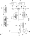
- FIG. 2 a schematic view of one embodiment of a system 100 for controlling hydraulic valve operation within a work vehicle is illustrated in accordance with aspects of the present subject matter.
- the system 100 will be described herein with reference to the work vehicle 10 described above with reference to FIG. 1 .
- the disclosed system 100 may generally be utilized with work vehicles having any other suitable vehicle configuration.
- hydraulic connections between components of the system 100 are shown in solid lines while electrical connection between components of the system 100 are shown in dashed lines.
- the system 100 includes a plurality of hydraulic loads of the work vehicle 10 (or an associated implement).
- the system 100 may be configured to regulate or otherwise control the hydraulic fluid flow within the work vehicle 10 such that the hydraulic fluid is supplied to the hydraulic loads in a manner that reduces the energy consumption of the vehicle 10.
- the system 100 includes the lift cylinders 36 and the tilt cylinders 38 of the work vehicle 10.
- the lift cylinders 36 are in parallel with the tilt cylinders 38.
- the hydraulic loads may correspond to any suitable fluid-powered devices on the work vehicle 10 (or an associated implement), such as other hydraulic cylinders, hydraulic motors, and/or the like.
- the system 100 may include any other suitable number of hydraulic loads, such as three or more hydraulic loads.
- the system 100 may include a pump 102 configured to supply hydraulic fluid to the hydraulic loads of the vehicle 10 (or an associated implement) via a fluid supply conduit 103.
- the system 100 includes first and second fluid conduits 104, 106 fluidly coupled between the fluid supply conduit 103 and the hydraulic loads.
- the pump 102 may be configured to supply hydraulic fluid to the lift cylinders 36 of the vehicle 10 via the fluid supply conduit 103 and the first fluid conduit 104.
- the pump 102 may be configured to supply hydraulic fluid to the tilt cylinders 38 of the vehicle 10 via the fluid supply conduit 103 and the second fluid conduit 106.
- the pump 102 may be configured to supply hydraulic fluid to any other suitable hydraulic loads of the vehicle 10 (or an associated implement). Additionally, the pump 102 may be in fluid communication with a fluid tank or reservoir 108 via a pump conduit 110 to allow hydraulic fluid stored within the reservoir 108 to be pressurized and supplied to the cylinders 36, 38.
- the pump 102 may be a variable displacement pump configured to discharge hydraulic fluid across a given pressure range.
- the pump 102 may supply pressurized hydraulic fluid within a range bounded by a minimum pressure and a maximum pressure capability of the variable displacement pump.
- a swash plash plate 112 may be configured to be controlled (e.g., hydraulically via a load sensing conduit 130) to adjust the position of the swash plate 112 of the pump 102, as necessary, based on the load applied to the hydraulic system of the vehicle 10.
- the pump 102 may correspond to any other suitable pressurized fluid source.
- the operation of the pump 102 may be controlled in any other suitable manner.
- the system 100 may include a plurality of flow control valves.
- the flow control valves may be fluidly coupled to the fluid supply conduits upstream of the corresponding hydraulic load(s) such that the flow control valves are configured to control the flow rate of the hydraulic fluid to the loads.
- the system 100 may include a first flow control valve 114 fluidly coupled to a downstream end of one branch of the fluid supply conduit 103 and to an upstream end of the first fluid conduit 104.
- the first flow control valve 114 is fluidly coupled between the fluid supply conduit 103 and the first fluid conduit 104.
- the first flow control valve 114 is upstream of the lift cylinders 36.
- the first flow control valve 114 may define an adjustable orifice 116.
- the first flow control valve 114 can control the flow rate of the hydraulic fluid supplied to the lift cylinders 36.
- the system 100 may include a second flow control valve 118 fluidly coupled to a downstream end of another branch of the fluid supply conduit 103 and to an upstream end of the second fluid conduit 106.
- the second flow control valve 118 is fluidly coupled between the fluid supply conduit 103 and the second fluid conduit 106.
- the second flow control valve 118 is upstream of the tilt cylinders 38.
- the second flow control valve 118 may define an adjustable orifice 120. In this respect, by adjusting the opening position or the cross-sectional area of the orifice 120, the second flow control valve 118 can control the flow rate of the hydraulic fluid supplied to the tilt cylinders 38.
- first and second flow control valves 114, 118 may be configured as any suitable valves defining adjustable orifices.
- first and second flow control valves 114, 118 may be proportional directional valves.
- Such valves 114, 118 may include actuators (e.g., solenoid actuators) configured to adjust the cross-sectional areas of the orifices 116, 120 in response to receiving control signals (e.g., electric current) from a computing system 148.
- control signals e.g., electric current
- the actuators may be configured to adjust the cross-sectional area of the orifices 116, 120 between a minimum flow position and a maximum flow position.
- the orifices 116, 120 When at the minimum flow position, the orifices 116, 120 may have their smallest cross-sectional areas (or, in some instances, may be closed). Conversely, when at the maximum flow position, the orifices 116, 120 may have their largest cross-sectional areas. In general, as the cross-sectional areas of the orifices 116, 120 increase, the pressure of hydraulic fluid needed to provide a selected flow rate to the lift and tilt cylinders 36, 38 may decrease.
- the system 100 may include a load sense conduit 130.
- the load sense conduit 130 may receive hydraulic fluid bled from the first or second fluid conduit 104, 106 having the greater pressure therein.
- the system 100 may include a first bleed conduit 136 fluidly coupled to the first fluid conduit 104 downstream of the first flow control valve 114.
- the system 100 may include a second bleed conduit 138 fluidly coupled to the second fluid conduit 106 downstream of the second flow control valve 118.
- the first bleed conduit 136 may receive hydraulic fluid bled from the first fluid conduit 104 and the second bleed conduit 138 may receive hydraulic fluid bled from the second fluid conduit 106.
- the system 100 may include a shuttle valve 140 fluidly coupled to the first and second bleed conduits 136, 138 and the load sense conduit 130.
- the shuttle valve 140 may, in turn, be configured to supply hydraulic fluid from the first or second bleed conduit 136, 138 having the greater pressure therein to the load sense conduit 130.
- the hydraulic fluid supplied to the load sense conduit 130 has the same pressure as the fluid supply conduit 104, 106 having the greater pressure therein.
- the hydraulic fluid within the load sense conduit 130 may be indicative of the load on the hydraulic system of the vehicle 10 and, thus, may be used to control the operation of the pump 102. More specifically, the load sense conduit 130 may supply the hydraulic fluid therein to a pump compensator 142. The pump compensator 142 may also receive a hydraulic fluid bled from the fluid supply conduit 103 via a bleed conduit 144. Additionally, the pump compensator 142 may have an associated a pump margin. In this respect, the pump compensator 142 may control the operation of the pump 102 such that the pump 102 discharges hydraulic fluid at a pressure that is equal to the sum of the pump margin and the pressure of the hydraulic fluid within the load sense conduit 130.
- the pump compensator 142 corresponds to a mechanical device.
- the pump compensator 142 may correspond to a passive hydraulic cylinder coupled to the swash plate 112 of the pump 102.
- hydraulic fluid from the load sense conduit 130 is supplied to one chamber of the cylinder and hydraulic fluid from the bleed conduit 144 is supplied to the other chamber of the cylinder.
- the pump compensator 142 may include a biasing element, such as a spring, in association within the cylinder to set the pump margin.
- the pump compensator 142 may move the swash plate 112 to increase the pressure of the hydraulic fluid discharged by the pump 102. Conversely, when the sum of the pressure within the load sense conduit 130 and the pump margin falls below the pressure within the bleed conduit 144, the pump compensator 142 may move the swash plate 112 to decrease the pressure of the hydraulic fluid discharged by the pump 102.
- the pump compensator 142 may have any suitable configuration that allows for control of the pump 102 based on the hydraulic fluid within the load sense conduit 130.
- the system 100 may include a computing system 148 communicatively coupled to one or more components of the work vehicle 10 and/or the system 100 to allow the operation of such components to be electronically or automatically controlled by the computing system 148.
- the computing system 148 may be communicatively coupled to the first flow control valve 114 via a communicative link 150.
- the computing system 148 may be configured to control the operation of the first flow control valve 114 to regulate the flow of the hydraulic fluid to the lift cylinders 36 such that the lift cylinders 36 raise and lower the loader arms 28 relative to the field surface.
- the computing system 148 may be communicatively coupled to the second flow control valve 118 via the communicative link 150.
- the computing system 148 may be configured to control the operation of the second flow control valve 118 to regulate the flow of the hydraulic fluid to the tilt cylinders 38 such that the tilt cylinders 38 adjust the tilt of the implement 32.
- the computing system 148 may be communicatively coupled to any other suitable valves or actuators of the system 100.
- the computing system 148 may comprise one or more processor-based devices, such as a given controller or computing device or any suitable combination of controllers or computing devices.
- the computing system 148 may include one or more processor(s) 152 and associated memory device(s) 154 configured to perform a variety of computer-implemented functions.
- processor refers not only to integrated circuits referred to in the art as being included in a computer, but also refers to a controller, a microcontroller, a microcomputer, a programmable logic circuit (PLC), an application specific integrated circuit, and other programmable circuits.
- the memory device(s) 154 of the computing system 148 may generally comprise memory element(s) including, but not limited to, a computer readable medium (e.g., random access memory RAM)), a computer readable non-volatile medium (e.g., a flash memory), a floppy disk, a compact disk-read only memory (CD-ROM), a magneto-optical disk (MOD), a digital versatile disk (DVD) and/or other suitable memory elements.
- Such memory device(s) 154 may generally be configured to store suitable computer-readable instructions that, when implemented by the processor(s) 152, configure the computing system 148 to perform various computer-implemented functions, such as one or more aspects of the methods and algorithms that will be described herein.
- the computing system 148 may also include various other suitable components, such as a communications circuit or module, one or more input/output channels, a data/control bus and/or the like.
- the various functions of the computing system 148 may be performed by a single processor-based device or may be distributed across any number of processor-based devices, in which instance such devices may be considered to form part of the computing system 148.
- the functions of the computing system 148 may be distributed across multiple application-specific controllers or computing devices, such as an implement controller, a navigation controller, an engine controller, and/or the like.
- the system 100 may also include a user interface 155.
- the user interface 155 may be configured to receive inputs (e.g., inputs associated with controlling the operation of the lift and tilt cylinders 36, 38).
- the user interface 155 may include one or more input devices, such as touchscreens, keypads, touchpads, knobs, buttons, sliders, switches, mice, microphones, and/or the like, which are configured to receive user inputs from the operator.
- the user interface 155 may include the joystick(s) 20.
- the user interface 155 may, in turn, be communicatively coupled to the computing system 148 via the communicative link 150 to permit the received inputs to be transmitted from the user interface 155 to the computing system 148.
- some embodiments of the user interface 155 may include one or more feedback devices (not shown), such as display screens, speakers, warning lights, and/or the like, which are configured to provide feedback from the computing system 148 to the operator.
- the user interface 155 may be mounted or otherwise positioned within the cab 18 of the vehicle 10. However, in alternative embodiments, the user interface 155 may mounted at any other suitable location.
- the system 100 may include a plurality of pressure sensors configured to capture data indicative of the pressure of the hydraulic fluid at differing locations within the hydraulic system of the vehicle 10.
- the system 100 includes a first pressure sensor 156 fluidly coupled to the first fluid conduit 104 downstream of the first flow control valve 114 and upstream of the lift cylinders 36.
- the first pressure sensor 156 may be configured to capture data indicative of the pressure of the hydraulic fluid being supplied to the lift cylinders 36 by the first flow control valve 114.
- the system 100 includes a second pressure sensor 158 fluidly coupled to the second fluid conduit 106 downstream of the second flow control valve 118 and upstream of the tilt cylinders 38.
- the second pressure sensor 158 may be configured to capture data indicative of the pressure of the hydraulic fluid being supplied to the tilt cylinders 36 by the second flow control valve 118.
- the system 100 may include a third pressure sensor 160 fluidly coupled to the fluid supply conduit 103.
- the third pressure sensor 160 may be configured to capture data indicative of the pressure of the hydraulic fluid being discharged by the pump 102.
- the first, second, and third pressure sensors 156, 158, 160 may be communicatively coupled to the computing system 148 via the communicative link 150.
- the computing system 148 may be configured to receive the captured data from the first, second, and third pressure sensors 156, 158, 160.
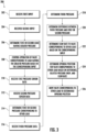
- control logic 200 that may be executed by the computing system 148 (or any other suitable computing system) for controlling hydraulic valve operation within a work vehicle is illustrated in accordance with aspects of the present subject matter.
- the control logic 200 shown in FIG. 3 is representative of steps of one embodiment of an algorithm that can be executed to control the operation of the hydraulic valves of a work vehicle in a manner that reduces the energy consumption of the vehicle.
- the control logic 200 can be executed when the operation of the pump 102 is controlled via the pump compensator 142 based the pressure of the hydraulic fluid present within the load sense conduit 130.
- control logic 200 may be advantageously utilized in association with a system installed on or forming part of a work vehicle having a hydraulically controlled pump to allow for real-time control of the operation of the hydraulic valves of the vehicle without requiring substantial computing resources and/or processing time.
- control logic 200 may be used in association with any other suitable system, application, and/or the like for controlling hydraulic valve operation within a work vehicle.
- the control logic 200 includes receiving a first input associated with controlling the operation of a first hydraulic load of the work vehicle 10 (or an associated implement).
- the computing system 148 may be communicatively coupled to the user interface 155 via the communicative link 150.
- the operator may provide a first input to the user interface 155.
- the first input may, in turn, be associated with controlling the operation of the lift cylinders 36.
- the operator may move one of the joysticks 20 a particular distance from its current position. Such distance may, in turn, be indicative of the operator's desired operation of the lift cylinders 36.
- the first input may be transmitted from the user interface 155 to the computing system 148 via the communicative link 150.
- the computing system 148 may receive the first input from any other suitable device, such as a remote computing device (e.g., a Smartphone, a remote database server, etc.) or a sensor.
- the control logic 200 includes receiving a second input associated with controlling the operation of a second hydraulic load of the work vehicle 10.
- the operator may provide a second input to the user interface 155.
- the second input may, in turn, be associated with controlling the operation of the tilt cylinders 38.
- the operator may move one of the joysticks 20 a particular distance from its current position. Such distance may, in turn, be indicative of the operator's desired operation of the tilt cylinders 38.
- the second input may be transmitted from the user interface 155 to the computing system 148 via the communicative link 150.
- the computing system 148 may receive the second input from any other suitable device, such as a remote computing device (e.g., a Smartphone, a remote database server, etc.) or a sensor.
- a remote computing device e.g., a Smartphone, a remote database server, etc.
- the control logic 200 includes determining one of the first or second hydraulic loads associated with the greater hydraulic fluid pressure based on the received first and second inputs. More specifically, in many instances, the first and second inputs received at (202) and (204), respectively, may result in the hydraulic fluid being supplied to the lift cylinders 36 and the tilt cylinders 38 at different pressures. For example, when the operator moves the joystick 20 associated with the lift cylinders 36 farther than the joystick 20 associated with the tilt cylinders 38, the hydraulic fluid may be supplied to the lift cylinders 36 at a greater pressure than the tilt cylinders 38. Thus, in such an instance, the lift cylinders 36 are associated with the greater hydraulic fluid pressure.
- the computing system 148 may analyze the first input received at (202) and the second input received at (204) to determine which of the lift cylinders 36 or the tilt cylinders 38 will have or be associated with the greater hydraulic fluid pressure. As will be described below, the hydraulic load having the greatest pressure will be controlled differently than the hydraulic load(s) having the lesser pressure(s).
- the control logic 200 includes controlling the operation of the first or second flow control valve corresponding to the one of the first or second hydraulic loads associated with the greater hydraulic fluid pressure based on the corresponding received first or second input.
- the computing system 148 may control the operation of the first or second flow control valve 114, 118 corresponding to the lift cylinders 36 or the tilt cylinders having the greater hydraulic pressure therein as determined at (206). For example, when it is determined at (206) that the lift cylinders 38 are associated with the greater hydraulic pressure, the computing system 148 controls the operation of the first flow control valve 114 based on the first input received at (202).
- the computing system 148 may access a valve area map stored within its memory 154 for the first flow control valve 114.
- the valve area map may, in turn, be a look-up table or other suitable data structure that correlates the first input received from the operator (e.g., the distance that the corresponding joystick 20 is moved) to the corresponding flow rate or an associated opening position/cross-sectional area of the orifice 116.
- the computing system 148 may transmit control signals to the first flow control valve 114 instructing the valve 114 to move its orifice 116 to the opening position determined based on the valve area map.
- the orifice opening position of the flow control valve 114, 118 corresponding to the hydraulic load associated with the greater hydraulic fluid pressure may be controlled entirely based on the corresponding input and without regard for the hydraulic fluid pressure within the first or second fluid conduits 104, 106.
- the pump 102 is controlled based on the pressure of the hydraulic fluid within the load sense conduit 130 to ensure that sufficient pressure is present within the corresponding conduit 104, 106 to operate the hydraulic load in accordance with the corresponding input.
- the control logic 200 includes receiving first pressure sensor data indicative of a first pressure of the hydraulic fluid being supplied to the first hydraulic load by the first flow control valve.
- the computing system 148 may be communicatively coupled to the first pressure sensor 156 via the communicative link 150. In this respect, during operation of the work vehicle 10, the computing system 148 may receive first pressure data from the first pressure sensor 156. Such first pressure data may, in turn, be indicative of the pressure of the hydraulic fluid being supplied to the lift cylinders 36 by the first flow control valve 114.
- the control logic 200 includes receiving second pressure sensor data indicative of a second pressure of the hydraulic fluid being supplied to the second hydraulic load by the second flow control valve.
- the computing system 148 may be communicatively coupled to the second pressure sensor 158 via the communicative link 150.
- the computing system 148 may receive second pressure data from the second pressure sensor 158.
- Such second pressure data may, in turn, be indicative of the pressure of the hydraulic fluid being supplied to the tilt cylinders 38 by the second flow control valve 118.
- the computing system 148 may receive pressure sensor data for those additional loads.
- the control logic 200 includes determining the first or second pressure of the hydraulic fluid being supplied to another of the first or second hydraulic loads based on the corresponding first or second pressure sensor data.
- the computing system 148 may determine the pressure of the hydraulic fluid being supplied to the other of the lift cylinders 36 or the tilt cylinders 38 (i.e., the load with lower pressure) based on the corresponding received pressure sensor data (e.g., either the first pressure sensor data received at (212) or the second pressure sensor data received at (214)).
- the computing system 148 determines the pressure of the hydraulic fluid being supplied to the tilt cylinders 38 by the second flow control valve 118 based on the second pressure sensor data received at (212). As will be described below, the pressure value determined at (214) is used when controlling the operation of the flow control valve 114, 118 corresponding to the lower pressure hydraulic load. Furthermore, in embodiments in which there are additional hydraulic loads, the computing system 148 may determine the pressure for the additional loads not having the greatest pressure.
- the control logic 200 includes receiving third pressure sensor data indicative of a third pressure of the hydraulic fluid being discharged by the pump.
- the computing system 148 may be communicatively coupled to the third pressure sensor 160 via the communicative link 150.
- the computing system 148 may receive third pressure data from the third pressure sensor 160.
- Such third pressure data may, in turn, be indicative of the pressure of the hydraulic fluid being discharged into the fluid supply conduit 103 by the pump 102.
- control logic 200 includes determining the third pressure of the hydraulic fluid being discharged by the pump.
- the computing system 148 may determine the pressure of the hydraulic fluid being discharged into the fluid supply conduit 103 by the pump 102 based on the third pressure sensor data received at (216). In some embodiments, (216) and (218) may not be performed.
- the control logic 200 includes controlling the operation of the first or second flow control valve 114, 118 corresponding the other of the first or second hydraulic loads (i.e., the lower pressure hydraulic load). Specifically, the operation of such valve 114, 118 is controlled based on the corresponding first or second input and the pressure determined at (214). Moreover, in some embodiments, the operation of such valve 114, 118 may be controlled based on the third pressure determined at (218) and/or a selected pressure drop across the valve 114, 118 corresponding to the hydraulic load having the greater hydraulic fluid pressure in addition to the corresponding first or second input and the pressure determined at (214). Additionally, in embodiments in which there are additional hydraulic loads, the computing system 148 may control the valves corresponding to the additional loads not having the greatest pressure in the same manner.
- the control logic 200 includes determining a difference between the determined third pressure and the determined first or second pressure.
- the computing system 148 may be configured to calculate the difference between the third pressure determined at (218) (i.e., the pressure of the hydraulic fluid being discharged by the pump 102) and the first or second pressure determined at (214) (i.e., the pressure of the hydraulic fluid being supplied to the hydraulic load having the lower pressure). For example, when it is determined at (206) that the lift cylinders 38 are associated with the greater hydraulic pressure, the computing system 148 determines the difference between the third pressure determined at (218) and the second pressure determined at (214). The difference determined at (220) is indicative of the pressure drop across the flow control valve 114, 118 corresponding the lower pressure hydraulic load. In some embodiments, (220) may not be performed.
- the control logic 200 includes determining a flow rate of hydraulic fluid to be supplied to the other of the first or second hydraulic loads based on the corresponding received first or second input.
- the computing system 148 may determine the flow rate of the hydraulic fluid to be supplied to the of the lift cylinders 36 or the tilt cylinders 38 having the lower pressure therein based on the corresponding received first or second input. For example, when it is determined at (206) that the lift cylinders 38 are associated with the greater hydraulic pressure, the computing system 148 determines the flow rate of the hydraulic fluid to be supplied to the tilt cylinders 38 based on the second input received at (204).
- the computing system 148 may access a valve area map stored within its memory 154 for the second flow control valve 118.
- the valve area map may, in turn, be a look-up table or other suitable data structure that correlates second input received from the operator (e.g., the distance that the corresponding joystick 20 is moved) to the corresponding flow rate or an associated opening position/cross-sectional area of the orifice 120.
- the control logic 200 includes determining an opening position of the adjustable orifice of the first or second flow control valve corresponding to the other of the first or second hydraulic loads based on the determined difference, a selected pressure drop, and the determined flow rate.
- the computing system 148 may determine the opening position for the adjustable orifice 116, 120 of the first or second flow control valve 114, 118 corresponding to the lift cylinders 36 or the tilt cylinders 38 having the lower pressure therein based on the difference determined at (220), the flow rate determined at (222), and/or a selected pressure drop across the valve 114, 118 corresponding to the lift cylinders 36 or the tilt cylinders 38 having the greater hydraulic fluid pressure (which may be a predetermined value stored in the memory 154).
- the computing system 148 determines the opening position for the adjustable orifice 120 of the second flow control valve 116 based on the difference determined at (220), the flow rate determined at (222), and/or a selected pressure drop across the first flow control valve 114. Specifically, in such instances, the computing system 148 may access an inverse valve area map stored within its memory 154 for the second flow control valve 118.
- the inverse valve area map may, in turn, be a look-up table or other suitable data structure that correlates the difference determined at (220), the flow rate determined at (222), and/or the selected pressure drop across the first flow control valve 114 to an associated opening position/cross-sectional area of the orifice 120.
- the control logic 200 includes controlling the operation of the first or second flow control valve corresponding to the other of the first or second hydraulic loads such that the corresponding adjustable orifice is moved to the determined opening position.
- the computing system 148 may control the operation of the first or second flow control valve 114, 118 corresponding to the lift cylinders 36 or the tilt cylinders 38 having the lower hydraulic fluid pressure such that the corresponding adjustable orifice 116, 120 is moved to the opening position determined at (224).
- the computing system 148 controls the operation of the second flow control valve 118 such that its adjustable orifice is moved to the opening position determined at (224).
- the computing system 148 may transmit control signals to the second flow control valve 118 via the communicative link 150 instructing the valve 118 to move its orifice 120 to the opening position determined at (224).
- the orifice opening position of the flow control valve 114, 118 corresponding to the hydraulic load associated with the lower hydraulic fluid pressure is controlled based on the corresponding received input and the pressure of the hydraulic fluid being supplied to that load.
- the execution of the control logic 200 improves the operation of the work vehicle 10. More specifically, as described above, when executing the control logic 200, the flow control valve 114, 118 corresponding to the hydraulic load (e.g., the lift cylinders 36 or the tilt cylinders 38) having the greater fluid pressure is controlled based on the corresponding received input received at (202) or (204). Additionally, the other flow control valve 114, 118 is controlled based on the corresponding input received at (202) or (204) and the pressure of the fluid being supplied the corresponding hydraulic load. This allows the flow control valves 114, 118 to supply the desired flow of hydraulic fluid to each hydraulic load regardless of the pressure of the hydraulic fluid being discharged by the pump 102 and without the need for compensator valves. Thus, the control logic 200 allows for the removal of the compensator valves from the work vehicle 10 in which its pump 102 is hydraulically controlled via the load sense conduit 130, thereby reducing the load on the pump 102 and improving the efficiency and fuel economy of the vehicle 10.
- the hydraulic load e.g., the lift
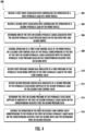
- FIG. 4 a flow diagram of one embodiment of a method 300 for controlling hydraulic valve operation within a work vehicle is illustrated in accordance with aspects of the present subject matter.
- the method 300 will be described herein with reference to the work vehicle 10 and the system 100 described above with reference to FIGS. 1-3 .
- the disclosed method 300 may generally be implemented with any work vehicle having any suitable vehicle configuration and/or within any system having any suitable system configuration.
- FIG. 4 depicts steps performed in a particular order for purposes of illustration and discussion, the methods discussed herein are not limited to any particular order or arrangement.
- steps of the methods disclosed herein can be omitted, rearranged, combined, and/or adapted in various ways without deviating from the scope of the present disclosure.
- the method 300 may include receiving, with a computing system, a first input associated with controlling the operation of a first hydraulic load of a work vehicle.
- the computing system 148 may be configured to receive a first input (e.g., a first operator input) from the user interface 155 via the communicative link 150.
- the first input may, in turn, be associated with controlling the operation of a first hydraulic load (e.g., the lift cylinders 36).
- the method 300 may include receiving, with the computing system, a second input associated with controlling the operation of a second hydraulic load of the work vehicle.
- the computing system 148 may be configured to receive a second input (e.g., a second operator input) from the user interface 155 via the communicative link 150.
- the second input may, in turn, be associated with controlling the operation of a second hydraulic load (e.g., the tilt cylinders 38).
- the method 300 may include determining, with the computing system, one of the first or second hydraulic loads associated with a greater hydraulic fluid pressure based on the received first and second inputs.
- the computing system 148 may be configured to analyze the received first and second input to determine which of the first or second hydraulic loads (e.g., the lift cylinders 36 or the tilt cylinders 38) is associated with or will have the greater hydraulic fluid pressure.
- the method 300 may include controlling, with the computing system, the operation of the first or second flow control valve corresponding to the one of the first or second hydraulic loads associated with the greater hydraulic fluid pressure based on the corresponding received first or second input.
- the computing system 148 may be configured to control the operation of the first or second flow control valve 114, 118 corresponding to the hydraulic load (e.g., the lift cylinders 36 or the tilt cylinders 38) associated with the greater hydraulic fluid pressure based on the corresponding first or second input.
- the method 300 may include receiving, with the computing system, first pressure sensor data indicative of a first pressure of the hydraulic fluid being supplied to the first hydraulic load by the first flow control valve.
- the computing system 148 may be configured to receive first pressure sensor data from the first pressure sensor 156 via the communicative link 150.
- the first pressure data is, in turn, indicative of the pressure of the hydraulic fluid being supplied to the first hydraulic load (e.g., the lift cylinders 36) by the first flow control valve 114.
- the method 300 may include receiving, with the computing system, second pressure sensor data indicative of a second pressure of the hydraulic fluid being supplied to the second hydraulic load by the second flow control valve.
- the computing system 148 may be configured to receive second pressure sensor data from the second pressure sensor 158 via the communicative link 150.
- the second pressure data is, in turn, indicative of the pressure of the hydraulic fluid being supplied to the second hydraulic load (e.g., the tilt cylinders 38) by the second flow control valve 118.
- the method 300 may include determining, with the computing system, the first or second pressure of the hydraulic fluid being supplied to another of the first or second hydraulic loads based on the corresponding received first or second pressure data.
- the computing system 148 may be configured to determine the pressure of the hydraulic fluid being supplied to the other of the first or second hydraulic loads (e.g., the lift cylinders 36 or the tilt cylinders 38 associated with the lower hydraulic fluid pressure) based on the corresponding first or second pressure data.
- the method 300 may include controlling, with the computing system, the operation of the first or second flow control valve corresponding to the other of the first or second hydraulic loads based on the corresponding received first or second input and the determined first or second pressure.
- the computing system 148 may be configured to control the operation of the first or second flow control valve 114, 118 corresponding to the other hydraulic loads (e.g., the lift cylinders 36 or the tilt cylinders 38 associated with the lower hydraulic fluid pressure) based on both the corresponding first or second input and the determined first or second pressure.
- the steps of the control logic 200 and the method 300 are performed by the computing system 148 upon loading and executing software code or instructions which are tangibly stored on a tangible computer readable medium, such as on a magnetic medium, e.g., a computer hard drive, an optical medium, e.g., an optical disc, solid-state memory, e.g., flash memory, or other storage media known in the art.
- a tangible computer readable medium such as on a magnetic medium, e.g., a computer hard drive, an optical medium, e.g., an optical disc, solid-state memory, e.g., flash memory, or other storage media known in the art.
- any of the functionality performed by the computing system 148 described herein, such as the control logic 200 and the method 300 is implemented in software code or instructions which are tangibly stored on a tangible computer readable medium.
- the computing system 148 loads the software code or instructions via a direct interface with the computer readable medium or via a wired and/or wireless network. Upon loading
- software code or “code” used herein refers to any instructions or set of instructions that influence the operation of a computer or controller. They may exist in a computer-executable form, such as machine code, which is the set of instructions and data directly executed by a computer's central processing unit or by a controller, a human-understandable form, such as source code, which may be compiled in order to be executed by a computer's central processing unit or by a controller, or an intermediate form, such as object code, which is produced by a compiler.
- the term "software code” or “code” also includes any human-understandable computer instructions or set of instructions, e.g., a script, that may be executed on the fly with the aid of an interpreter executed by a computer's central processing unit or by a controller.
Landscapes
- Engineering & Computer Science (AREA)
- General Engineering & Computer Science (AREA)
- Physics & Mathematics (AREA)
- Fluid Mechanics (AREA)
- Mining & Mineral Resources (AREA)
- Civil Engineering (AREA)
- Structural Engineering (AREA)
- Mechanical Engineering (AREA)
- Chemical & Material Sciences (AREA)
- Analytical Chemistry (AREA)
- Fluid-Pressure Circuits (AREA)
Abstract
Description
- The present disclosure generally relates to work vehicles and, more particularly, to systems and methods for controlling the operation of hydraulic valves within a work vehicle.
- A work vehicle, such as a construction vehicle, an agricultural vehicle, or the like, generally includes a hydraulic system to actuate various components of the vehicle. For example, the hydraulic system may to raise and lower an implement, such as a bucket, at the operator's command. As such, the hydraulic system generally includes one or more hydraulic loads (e.g., hydraulic actuators, motors, and/or the like) and a pump configured to supply hydraulic fluid to the load(s)
- Additionally, the hydraulic system may include various valves and other flow control devices to control the flow of the hydraulic fluid from the pump to the hydraulic load(s). For example, many hydraulic systems include a flow control valve having an adjustable orifice positioned upstream of each hydraulic load that controls the flow rate of the hydraulic fluid being delivered to the corresponding load(s). In this respect, each flow control valve controls the flow rate of the hydraulic fluid being supplied to the downstream load(s) based on the opening position or cross-sectional area of its orifice.
- Furthermore, many hydraulic systems include a compensator valve positioned adjacent to each flow control valve. The compensator valve, in turn, maintains a predetermined pressure drop across the corresponding flow control valve regardless of the opening position of its orifice. However, in many instances, the compensator valve creates a greater than necessary pressure drop across the corresponding flow control valve. This results in a greater load on the pump, thereby increasing the energy consumption of the work vehicle and reducing its fuel economy.
- Accordingly, an improved system and method for controlling hydraulic valve operation within a work vehicle would be welcomed in the technology. In particular, an improved system and method for controlling hydraulic valve operation within a work vehicle that reduces the energy consumption of the vehicle would be welcomed in the technology.
- Aspects and advantages of the technology will be set forth in part in the following description, or may be obvious from the description, or may be learned through practice of the technology.
- In one aspect, the present subject matter is directed to a work vehicle. The work vehicle includes a first hydraulic load, a second hydraulic load in parallel with the first hydraulic load, and a pump configured to supply hydraulic fluid to the first and second hydraulic loads via first and second fluid conduits, respectively. Furthermore, the work vehicle includes a first flow control valve defining an adjustable orifice, with the first flow control valve fluidly coupled to the first fluid conduit upstream of the first hydraulic load such that the first flow control valve is configured to control a flow rate of the hydraulic fluid to the first hydraulic load. Additionally, the work vehicle includes a second flow control valve defining an adjustable orifice, with the second flow control valve fluidly coupled to the second fluid conduit upstream of the second hydraulic load such that the second flow control valve is configured to control a flow rate of the hydraulic fluid to the second hydraulic load. Moreover, the work vehicle includes a first pressure sensor configured to capture data indicative of a first pressure of the hydraulic fluid being supplied to the first hydraulic load by the first flow control valve, a second pressure sensor configured to capture data indicative of a second pressure of the hydraulic fluid being supplied to the second hydraulic load by the second flow control valve, and a computing system communicatively coupled to the first and second pressure sensors. The computing system is configured to receive a first input associated with controlling an operation of the first hydraulic load and receive a second input associated with controlling an operation of the second hydraulic load. In addition, the computing system is configured to determine one of the first or second hydraulic loads associated with a greater hydraulic fluid pressure based on the received first and second inputs. Furthermore, the computing system is configured to control an operation of the first or second flow control valve corresponding to the one of the first or second hydraulic loads associated with the greater hydraulic fluid pressure based on the corresponding received first or second input. Additionally, the computing system is configured to determine the first or second pressure of the hydraulic fluid being supplied to another of the first or second hydraulic loads based on the data received from the corresponding first or second pressure sensor. Moreover, the computing system is configured to control an operation of the first or second flow control valve corresponding to the other of the first or second hydraulic loads based on the corresponding received first or second input and the determined first or second pressure.
- In another aspect, the present subject matter is directed to a system for controlling hydraulic valve operation within a work vehicle. The system includes a first hydraulic load, a second hydraulic load in parallel with the first hydraulic load, and a pump configured to supply hydraulic fluid to the first and second hydraulic loads via first and second fluid conduits, respectively. Furthermore, the system includes a first flow control valve defining an adjustable orifice, with the first flow control valve fluidly coupled to the first fluid conduit upstream of the first hydraulic load such that the first flow control valve is configured to control a flow rate of the hydraulic fluid to the first hydraulic load. Additionally, the system includes a second flow control valve defining an adjustable orifice, with the second flow control valve fluidly coupled to the second fluid conduit upstream of the second hydraulic load such that the second flow control valve is configured to control a flow rate of the hydraulic fluid to the second hydraulic load. Moreover, the system includes a first pressure sensor configured to capture data indicative of a first pressure of the hydraulic fluid being supplied to the first hydraulic load by the first flow control valve, a second pressure sensor configured to capture data indicative of a second pressure of the hydraulic fluid being supplied to the second hydraulic load by the second flow control valve, and a computing system communicatively coupled to the first and second pressure sensors. The computing system is configured to receive a first input associated with controlling an operation of the first hydraulic load and receive a second input associated with controlling an operation of the second hydraulic load. In addition, the computing system is configured to determine one of the first or second hydraulic loads associated with a greater hydraulic fluid pressure based on the received first and second inputs. Furthermore, the computing system is configured to control an operation of the first or second flow control valve corresponding to the one of the first or second hydraulic loads associated with the greater hydraulic fluid pressure based on the corresponding received first or second input. Additionally, the computing system is configured to determine the first or second pressure of the hydraulic fluid being supplied to another of the first or second hydraulic loads based on the data received from the corresponding first or second pressure sensor. Moreover, the computing system is configured to control an operation of the first or second flow control valve corresponding to the other of the first or second hydraulic loads based on the corresponding received first or second input and the determined first or second pressure.
- In a further aspect, the present subject matter is directed to a method for controlling hydraulic valve operation within a work vehicle. The work vehicle, in turn, includes first and second hydraulic loads in parallel, a pump configured to supply hydraulic fluid to the first and second hydraulic loads, respectively. Furthermore, the work vehicle includes a first flow control valve configured to control a flow rate of the hydraulic fluid to the first hydraulic load and a second flow control valve configured to control a flow rate of the hydraulic fluid to the second hydraulic load. The method includes receiving, with a computing system, a first input associated with controlling an operation of the first hydraulic load. Additionally, the method includes receiving, with the computing system, a second input associated with controlling an operation of the second hydraulic load. Moreover, the method includes determining, with the computing system, one of the first or second hydraulic loads associated with a greater hydraulic fluid pressure based on the received first and second inputs. In addition, the method includes controlling, with the computing system, an operation of the first or second flow control valve corresponding to the one of the first or second hydraulic loads associated with the greater hydraulic fluid pressure based on the corresponding received first or second input. Furthermore, the method includes receiving, with the computing system, first pressure sensor data indicative of a first pressure of the hydraulic fluid being supplied to the first hydraulic load by the first flow control valve. Additionally, the method includes receiving, with the computing system, second pressure sensor data indicative of a second pressure of the hydraulic fluid being supplied to the second hydraulic load by the second flow control valve. Moreover, the method includes determining, with the computing system, the first or second pressure of the hydraulic fluid being supplied to another of the first or second hydraulic loads based on the corresponding received first or second pressure data. In addition, the method includes controlling, with the computing system, an operation of the first or second flow control valve corresponding to the other of the first or second hydraulic loads based on the corresponding received first or second input and the determined first or second pressure.
- These and other features, aspects and advantages of the present technology will become better understood with reference to the following description and appended claims. The accompanying drawings, which are incorporated in and constitute a part of this specification, illustrate embodiments of the technology and, together with the description, serve to explain the principles of the technology.
- A full and enabling disclosure of the present technology, including the best mode thereof, directed to one of ordinary skill in the art, is set forth in the specification, which makes reference to the appended figures, in which:
-
FIG. 1 illustrates a side view of one embodiment of a work vehicle in accordance with aspects of the present subject matter; -
FIG. 2 illustrates a schematic view of one embodiment of a system for controlling hydraulic valve operation within a work vehicle in accordance with aspects of the present subject matter; -
FIG. 3 illustrates a flow diagram providing one embodiment of example control logic for controlling hydraulic valve operation within a work vehicle in accordance with aspects of the present subject matter; and -
FIG. 4 illustrates a flow diagram of one embodiment of a method for controlling hydraulic valve operation within a work vehicle in accordance with aspects of the present subject matter. - Repeat use of reference characters in the present specification and drawings is intended to represent the same or analogous features or elements of the present technology.
- Reference now will be made in detail to embodiments of the invention, one or more examples of which are illustrated in the drawings. Each example is provided by way of explanation of the invention, not limitation of the invention. In fact, it will be apparent to those skilled in the art that various modifications and variations can be made in the present invention. For instance, features illustrated or described as part of one embodiment can be used with another embodiment to yield a still further embodiment. Thus, it is intended that the present invention covers such modifications and variations as come within the scope of the appended claims and their equivalents.
- In general, the present subject matter is directed to a system and method for controlling hydraulic valve operation within a work vehicle. As will be described below, the work vehicle includes first and second hydraulic loads (e.g., hydraulic cylinders) in parallel with each other. Furthermore, the work vehicle includes a pump configured to supply hydraulic fluid to the first and second hydraulic loads via first and second fluid conduits, respectively. Additionally, the work vehicle includes a first flow control valve fluidly coupled to the first fluid conduit upstream of the first hydraulic load such that the first flow control valve is configured to control the flow rate of the hydraulic fluid to the first hydraulic load. Moreover, the work vehicle includes a second flow control valve fluidly coupled to the second fluid conduit upstream of the second hydraulic load such that the second flow control valve is configured to control the flow rate of the hydraulic fluid to the second hydraulic load. In addition, the work vehicle includes a load sense conduit fluidly coupled to the first and second fluid conduits downstream of the first and second flow control valves. As such, the operation of the pump is controlled based on the pressure of the hydraulic fluid within the load sense conduit.
- In several embodiments, a computing system of the disclosed system is configured to control the operation of the first and second flow control valves. More specifically, the computing system may receive first and second inputs (e.g., from a user interface of the vehicle) associated with controlling the operation of the first and second hydraulic loads, respectively. Furthermore, the computing system may determine the first or second hydraulic load having the greater hydraulic fluid pressure based on the received first and second inputs. Additionally, the computing system may control the operation of the first or second flow control valve corresponding to the hydraulic load having the greater hydraulic fluid pressure based on the corresponding first or second input. Moreover, the computing system may determine the pressure of the hydraulic fluid being supplied to the other of the first or second hydraulic loads based on received pressure sensor data. In addition, the computing system may control the operation of the first or second flow control valve corresponding to the other hydraulic load based on the corresponding first or second input and the determined pressure.
- For example, in certain instances, the received first and second inputs may indicate that the first hydraulic load is to receive hydraulic fluid at a greater pressure than the second hydraulic load. In such instances, the computing system may control the operation of the first flow control valve based on the received first input. That is, the position of the adjustable orifice of the first flow control valve may be set based on the received first input. Furthermore, in such instances, the computing system may determine the pressure of the hydraulic fluid being supplied to the second hydraulic load. Thereafter, the computing system may control the operation of the second flow control valve based on the received second input and the pressure of the hydraulic fluid being supplied to the second hydraulic load.
- The disclosed system and method improve the operation of the work vehicle. More specifically, as described above, the flow control valve corresponding to the hydraulic load having the greater fluid pressure is controlled based on the corresponding received input. Additionally, the other flow control valve is controlled based on the corresponding received input and the pressure of the fluid being supplied the corresponding hydraulic load. This allows the flow control valves to supply the desired flow of hydraulic fluid to each hydraulic load regardless of the pressure of the hydraulic fluid being discharged by the pump and without the need for compensator valves. Thus, the disclosed system and method allows for the removal of the compensator valves from the work vehicle, thereby reducing the load on the pump and improving the efficiency and fuel economy of the vehicle.
- Referring now to the drawings,
FIG. 1 illustrates a side view of one embodiment of awork vehicle 10. As shown, thework vehicle 10 is configured as a wheel loader. However, in other embodiments, thework vehicle 10 may be configured as any other suitable work vehicle known in the art, such as any other construction vehicle (e.g., another type of loader, a dozer, a grader, etc.), an agricultural vehicle (e.g., a tractor, a harvester, a sprayer, etc.), or the like. - As shown in
FIG. 1 , thework vehicle 10 includes a pair offront wheels 12, a pair orrear wheels 14, and achassis 16 coupled to and supported by thewheels cab 18 may be supported by a portion of thechassis 16 and may house various control or input devices (e.g., levers, pedals, control panels, buttons and/or the like) for permitting an operator to control the operation of thework vehicle 10. For instance, as shown inFIG. 1 , thework vehicle 10 includes one or more joysticks orcontrol levers 20 for controlling the operation of one or more components of alift assembly 22 of thework vehicle 10. - As shown in
FIG. 1 , thelift assembly 22 includes a pair of loader arms 24 (one of which is shown) extending lengthwise between a first end 26 and asecond end 28. In this respect, the first ends 26 of theloader arms 24 may be pivotably coupled to thechassis 16 at pivot joints 30. Similarly, the second ends 28 of theloader arms 24 may be pivotably coupled to a suitable implement 32 of the work vehicle 10 (e.g., a bucket, fork, blade, and/or the like) at pivot joints 34. In addition, thelift assembly 22 also includes a plurality of hydraulic actuators for controlling the movement of theloader arms 24 and the implement 32. For instance, thelift assembly 22 may include a pair of hydraulic lift cylinders 36 (one of which is shown) coupled between thechassis 16 and theloader arms 24 for raising and lowering theloader arms 24 relative to the ground. Moreover, thelift assembly 22 may include a pair of hydraulic tilt cylinders 38 (one of which is shown) for tilting or pivoting the implement 32 relative to theloader arms 24. - It should be appreciated that the configuration of the
work vehicle 10 described above and shown inFIG. 1 is provided only to place the present subject matter in an exemplary field of use. Thus, it should be appreciated that the present subject matter may be readily adaptable to any manner of work vehicle configuration. - Referring now to
FIG. 2 , a schematic view of one embodiment of asystem 100 for controlling hydraulic valve operation within a work vehicle is illustrated in accordance with aspects of the present subject matter. In general, thesystem 100 will be described herein with reference to thework vehicle 10 described above with reference toFIG. 1 . However, it should be appreciated by those of ordinary skill in the art that the disclosedsystem 100 may generally be utilized with work vehicles having any other suitable vehicle configuration. For purposes of illustration, hydraulic connections between components of thesystem 100 are shown in solid lines while electrical connection between components of thesystem 100 are shown in dashed lines. - In several embodiments, as shown in
FIG. 2 , thesystem 100 includes a plurality of hydraulic loads of the work vehicle 10 (or an associated implement). In this respect, as will be described below, thesystem 100 may be configured to regulate or otherwise control the hydraulic fluid flow within thework vehicle 10 such that the hydraulic fluid is supplied to the hydraulic loads in a manner that reduces the energy consumption of thevehicle 10. For example, in the illustrated embodiment, thesystem 100 includes thelift cylinders 36 and thetilt cylinders 38 of thework vehicle 10. As shown, thelift cylinders 36 are in parallel with thetilt cylinders 38. However, the hydraulic loads may correspond to any suitable fluid-powered devices on the work vehicle 10 (or an associated implement), such as other hydraulic cylinders, hydraulic motors, and/or the like. Moreover, thesystem 100 may include any other suitable number of hydraulic loads, such as three or more hydraulic loads. - Furthermore, the
system 100 may include apump 102 configured to supply hydraulic fluid to the hydraulic loads of the vehicle 10 (or an associated implement) via afluid supply conduit 103. In addition, thesystem 100 includes first and secondfluid conduits fluid supply conduit 103 and the hydraulic loads. Specifically, in several embodiments, thepump 102 may be configured to supply hydraulic fluid to thelift cylinders 36 of thevehicle 10 via thefluid supply conduit 103 and the firstfluid conduit 104. Moreover, in several embodiments, thepump 102 may be configured to supply hydraulic fluid to thetilt cylinders 38 of thevehicle 10 via thefluid supply conduit 103 and the secondfluid conduit 106. However, in alternative embodiments, thepump 102 may be configured to supply hydraulic fluid to any other suitable hydraulic loads of the vehicle 10 (or an associated implement). Additionally, thepump 102 may be in fluid communication with a fluid tank orreservoir 108 via apump conduit 110 to allow hydraulic fluid stored within thereservoir 108 to be pressurized and supplied to thecylinders - In several embodiments, the
pump 102 may be a variable displacement pump configured to discharge hydraulic fluid across a given pressure range. Specifically, thepump 102 may supply pressurized hydraulic fluid within a range bounded by a minimum pressure and a maximum pressure capability of the variable displacement pump. In this respect, aswash plash plate 112 may be configured to be controlled (e.g., hydraulically via a load sensing conduit 130) to adjust the position of theswash plate 112 of thepump 102, as necessary, based on the load applied to the hydraulic system of thevehicle 10. However, in other embodiments, thepump 102 may correspond to any other suitable pressurized fluid source. Moreover, the operation of thepump 102 may be controlled in any other suitable manner. - Furthermore, the
system 100 may include a plurality of flow control valves. In general, the flow control valves may be fluidly coupled to the fluid supply conduits upstream of the corresponding hydraulic load(s) such that the flow control valves are configured to control the flow rate of the hydraulic fluid to the loads. Specifically, in several embodiments, thesystem 100 may include a firstflow control valve 114 fluidly coupled to a downstream end of one branch of thefluid supply conduit 103 and to an upstream end of the firstfluid conduit 104. Thus, the firstflow control valve 114 is fluidly coupled between thefluid supply conduit 103 and the firstfluid conduit 104. Additionally, the firstflow control valve 114 is upstream of thelift cylinders 36. As shown, the firstflow control valve 114 may define anadjustable orifice 116. In this respect, by adjusting the opening position or the cross-sectional area of theorifice 116, the firstflow control valve 114 can control the flow rate of the hydraulic fluid supplied to thelift cylinders 36. Moreover, in such embodiments, thesystem 100 may include a secondflow control valve 118 fluidly coupled to a downstream end of another branch of thefluid supply conduit 103 and to an upstream end of the secondfluid conduit 106. Thus, the secondflow control valve 118 is fluidly coupled between thefluid supply conduit 103 and the secondfluid conduit 106. In addition, the secondflow control valve 118 is upstream of thetilt cylinders 38. As shown, the secondflow control valve 118 may define anadjustable orifice 120. In this respect, by adjusting the opening position or the cross-sectional area of theorifice 120, the secondflow control valve 118 can control the flow rate of the hydraulic fluid supplied to thetilt cylinders 38. - The first and second
flow control valves flow control valves Such valves orifices computing system 148. As such, the actuators may be configured to adjust the cross-sectional area of theorifices orifices orifices orifices tilt cylinders - Additionally, the
system 100 may include aload sense conduit 130. In general, theload sense conduit 130 may receive hydraulic fluid bled from the first or secondfluid conduit system 100 may include afirst bleed conduit 136 fluidly coupled to the firstfluid conduit 104 downstream of the firstflow control valve 114. Furthermore, thesystem 100 may include asecond bleed conduit 138 fluidly coupled to the secondfluid conduit 106 downstream of the secondflow control valve 118. Thus, thefirst bleed conduit 136 may receive hydraulic fluid bled from the firstfluid conduit 104 and thesecond bleed conduit 138 may receive hydraulic fluid bled from the secondfluid conduit 106. Additionally, thesystem 100 may include ashuttle valve 140 fluidly coupled to the first andsecond bleed conduits load sense conduit 130. Theshuttle valve 140 may, in turn, be configured to supply hydraulic fluid from the first orsecond bleed conduit load sense conduit 130. In this respect, the hydraulic fluid supplied to theload sense conduit 130 has the same pressure as thefluid supply conduit - The hydraulic fluid within the
load sense conduit 130 may be indicative of the load on the hydraulic system of thevehicle 10 and, thus, may be used to control the operation of thepump 102. More specifically, theload sense conduit 130 may supply the hydraulic fluid therein to apump compensator 142. Thepump compensator 142 may also receive a hydraulic fluid bled from thefluid supply conduit 103 via ableed conduit 144. Additionally, thepump compensator 142 may have an associated a pump margin. In this respect, thepump compensator 142 may control the operation of thepump 102 such that thepump 102 discharges hydraulic fluid at a pressure that is equal to the sum of the pump margin and the pressure of the hydraulic fluid within theload sense conduit 130. - In this illustrated embodiment, the
pump compensator 142 corresponds to a mechanical device. For instance, thepump compensator 142 may correspond to a passive hydraulic cylinder coupled to theswash plate 112 of thepump 102. In such an embodiment, hydraulic fluid from theload sense conduit 130 is supplied to one chamber of the cylinder and hydraulic fluid from thebleed conduit 144 is supplied to the other chamber of the cylinder. Moreover, thepump compensator 142 may include a biasing element, such as a spring, in association within the cylinder to set the pump margin. In this respect, when the sum of the pressure within theload sense conduit 130 and the pump margin exceeds the pressure within thebleed conduit 144, thepump compensator 142 may move theswash plate 112 to increase the pressure of the hydraulic fluid discharged by thepump 102. Conversely, when the sum of the pressure within theload sense conduit 130 and the pump margin falls below the pressure within thebleed conduit 144, thepump compensator 142 may move theswash plate 112 to decrease the pressure of the hydraulic fluid discharged by thepump 102. However, in other embodiments, thepump compensator 142 may have any suitable configuration that allows for control of thepump 102 based on the hydraulic fluid within theload sense conduit 130. - Furthermore, the
system 100 may include acomputing system 148 communicatively coupled to one or more components of thework vehicle 10 and/or thesystem 100 to allow the operation of such components to be electronically or automatically controlled by thecomputing system 148. For instance, thecomputing system 148 may be communicatively coupled to the firstflow control valve 114 via acommunicative link 150. As such, thecomputing system 148 may be configured to control the operation of the firstflow control valve 114 to regulate the flow of the hydraulic fluid to thelift cylinders 36 such that thelift cylinders 36 raise and lower theloader arms 28 relative to the field surface. Furthermore, thecomputing system 148 may be communicatively coupled to the secondflow control valve 118 via thecommunicative link 150. In this respect, thecomputing system 148 may be configured to control the operation of the secondflow control valve 118 to regulate the flow of the hydraulic fluid to thetilt cylinders 38 such that thetilt cylinders 38 adjust the tilt of the implement 32. In alternative embodiments, thecomputing system 148 may be communicatively coupled to any other suitable valves or actuators of thesystem 100. - In general, the
computing system 148 may comprise one or more processor-based devices, such as a given controller or computing device or any suitable combination of controllers or computing devices. Thus, in several embodiments, thecomputing system 148 may include one or more processor(s) 152 and associated memory device(s) 154 configured to perform a variety of computer-implemented functions. As used herein, the term "processor" refers not only to integrated circuits referred to in the art as being included in a computer, but also refers to a controller, a microcontroller, a microcomputer, a programmable logic circuit (PLC), an application specific integrated circuit, and other programmable circuits. Additionally, the memory device(s) 154 of thecomputing system 148 may generally comprise memory element(s) including, but not limited to, a computer readable medium (e.g., random access memory RAM)), a computer readable non-volatile medium (e.g., a flash memory), a floppy disk, a compact disk-read only memory (CD-ROM), a magneto-optical disk (MOD), a digital versatile disk (DVD) and/or other suitable memory elements. Such memory device(s) 154 may generally be configured to store suitable computer-readable instructions that, when implemented by the processor(s) 152, configure thecomputing system 148 to perform various computer-implemented functions, such as one or more aspects of the methods and algorithms that will be described herein. In addition, thecomputing system 148 may also include various other suitable components, such as a communications circuit or module, one or more input/output channels, a data/control bus and/or the like. - The various functions of the
computing system 148 may be performed by a single processor-based device or may be distributed across any number of processor-based devices, in which instance such devices may be considered to form part of thecomputing system 148. For instance, the functions of thecomputing system 148 may be distributed across multiple application-specific controllers or computing devices, such as an implement controller, a navigation controller, an engine controller, and/or the like. - Furthermore, in some embodiment, the
system 100 may also include auser interface 155. More specifically, theuser interface 155 may be configured to receive inputs (e.g., inputs associated with controlling the operation of the lift andtilt cylinders 36, 38). As such, theuser interface 155 may include one or more input devices, such as touchscreens, keypads, touchpads, knobs, buttons, sliders, switches, mice, microphones, and/or the like, which are configured to receive user inputs from the operator. For example, in one embodiment, theuser interface 155 may include the joystick(s) 20. Theuser interface 155 may, in turn, be communicatively coupled to thecomputing system 148 via thecommunicative link 150 to permit the received inputs to be transmitted from theuser interface 155 to thecomputing system 148. In addition, some embodiments of theuser interface 155 may include one or more feedback devices (not shown), such as display screens, speakers, warning lights, and/or the like, which are configured to provide feedback from thecomputing system 148 to the operator. In one embodiment, theuser interface 155 may be mounted or otherwise positioned within thecab 18 of thevehicle 10. However, in alternative embodiments, theuser interface 155 may mounted at any other suitable location. - In several embodiments, the
system 100 may include a plurality of pressure sensors configured to capture data indicative of the pressure of the hydraulic fluid at differing locations within the hydraulic system of thevehicle 10. Specifically, thesystem 100 includes afirst pressure sensor 156 fluidly coupled to the firstfluid conduit 104 downstream of the firstflow control valve 114 and upstream of thelift cylinders 36. As such, thefirst pressure sensor 156 may be configured to capture data indicative of the pressure of the hydraulic fluid being supplied to thelift cylinders 36 by the firstflow control valve 114. Furthermore, thesystem 100 includes asecond pressure sensor 158 fluidly coupled to the secondfluid conduit 106 downstream of the secondflow control valve 118 and upstream of thetilt cylinders 38. In this respect, thesecond pressure sensor 158 may be configured to capture data indicative of the pressure of the hydraulic fluid being supplied to thetilt cylinders 36 by the secondflow control valve 118. Moreover, thesystem 100 may include athird pressure sensor 160 fluidly coupled to thefluid supply conduit 103. Thus, thethird pressure sensor 160 may be configured to capture data indicative of the pressure of the hydraulic fluid being discharged by thepump 102. As shown, the first, second, andthird pressure sensors computing system 148 via thecommunicative link 150. As such, thecomputing system 148 may be configured to receive the captured data from the first, second, andthird pressure sensors - Referring now to
FIG. 3 , a flow diagram of one embodiment ofexample control logic 200 that may be executed by the computing system 148 (or any other suitable computing system) for controlling hydraulic valve operation within a work vehicle is illustrated in accordance with aspects of the present subject matter. Specifically, thecontrol logic 200 shown inFIG. 3 is representative of steps of one embodiment of an algorithm that can be executed to control the operation of the hydraulic valves of a work vehicle in a manner that reduces the energy consumption of the vehicle. Moreover, thecontrol logic 200 can be executed when the operation of thepump 102 is controlled via thepump compensator 142 based the pressure of the hydraulic fluid present within theload sense conduit 130. Thus, in several embodiments, thecontrol logic 200 may be advantageously utilized in association with a system installed on or forming part of a work vehicle having a hydraulically controlled pump to allow for real-time control of the operation of the hydraulic valves of the vehicle without requiring substantial computing resources and/or processing time. However, in other embodiments, thecontrol logic 200 may be used in association with any other suitable system, application, and/or the like for controlling hydraulic valve operation within a work vehicle. - As shown in FIG. 6, at (202), the
control logic 200 includes receiving a first input associated with controlling the operation of a first hydraulic load of the work vehicle 10 (or an associated implement). Specifically, as mentioned above, in several embodiments, thecomputing system 148 may be communicatively coupled to theuser interface 155 via thecommunicative link 150. In this respect, the operator may provide a first input to theuser interface 155. The first input may, in turn, be associated with controlling the operation of thelift cylinders 36. For example, in one embodiment, the operator may move one of the joysticks 20 a particular distance from its current position. Such distance may, in turn, be indicative of the operator's desired operation of thelift cylinders 36. Thereafter, the first input may be transmitted from theuser interface 155 to thecomputing system 148 via thecommunicative link 150. Alternatively, thecomputing system 148 may receive the first input from any other suitable device, such as a remote computing device (e.g., a Smartphone, a remote database server, etc.) or a sensor. - Furthermore, at (204), the
control logic 200 includes receiving a second input associated with controlling the operation of a second hydraulic load of thework vehicle 10. Specifically, in several embodiments, the operator may provide a second input to theuser interface 155. The second input may, in turn, be associated with controlling the operation of thetilt cylinders 38. For example, in one embodiment, the operator may move one of the joysticks 20 a particular distance from its current position. Such distance may, in turn, be indicative of the operator's desired operation of thetilt cylinders 38. Thereafter, the second input may be transmitted from theuser interface 155 to thecomputing system 148 via thecommunicative link 150. Alternatively, thecomputing system 148 may receive the second input from any other suitable device, such as a remote computing device (e.g., a Smartphone, a remote database server, etc.) or a sensor. - Additionally, at (206), the
control logic 200 includes determining one of the first or second hydraulic loads associated with the greater hydraulic fluid pressure based on the received first and second inputs. More specifically, in many instances, the first and second inputs received at (202) and (204), respectively, may result in the hydraulic fluid being supplied to thelift cylinders 36 and thetilt cylinders 38 at different pressures. For example, when the operator moves thejoystick 20 associated with thelift cylinders 36 farther than thejoystick 20 associated with thetilt cylinders 38, the hydraulic fluid may be supplied to thelift cylinders 36 at a greater pressure than thetilt cylinders 38. Thus, in such an instance, thelift cylinders 36 are associated with the greater hydraulic fluid pressure. As such, in several embodiments, thecomputing system 148 may analyze the first input received at (202) and the second input received at (204) to determine which of thelift cylinders 36 or thetilt cylinders 38 will have or be associated with the greater hydraulic fluid pressure. As will be described below, the hydraulic load having the greatest pressure will be controlled differently than the hydraulic load(s) having the lesser pressure(s). - Moreover, at (208), the
control logic 200 includes controlling the operation of the first or second flow control valve corresponding to the one of the first or second hydraulic loads associated with the greater hydraulic fluid pressure based on the corresponding received first or second input. In several embodiments, thecomputing system 148 may control the operation of the first or secondflow control valve lift cylinders 36 or the tilt cylinders having the greater hydraulic pressure therein as determined at (206). For example, when it is determined at (206) that thelift cylinders 38 are associated with the greater hydraulic pressure, thecomputing system 148 controls the operation of the firstflow control valve 114 based on the first input received at (202). Specifically, in such instances, thecomputing system 148 may access a valve area map stored within itsmemory 154 for the firstflow control valve 114. The valve area map may, in turn, be a look-up table or other suitable data structure that correlates the first input received from the operator (e.g., the distance that the correspondingjoystick 20 is moved) to the corresponding flow rate or an associated opening position/cross-sectional area of theorifice 116. Thereafter, thecomputing system 148 may transmit control signals to the firstflow control valve 114 instructing thevalve 114 to move itsorifice 116 to the opening position determined based on the valve area map. Thus, the orifice opening position of theflow control valve fluid conduits pump 102 is controlled based on the pressure of the hydraulic fluid within theload sense conduit 130 to ensure that sufficient pressure is present within thecorresponding conduit - In addition, at (210), the
control logic 200 includes receiving first pressure sensor data indicative of a first pressure of the hydraulic fluid being supplied to the first hydraulic load by the first flow control valve. Specifically, as mentioned above, in several embodiments, thecomputing system 148 may be communicatively coupled to thefirst pressure sensor 156 via thecommunicative link 150. In this respect, during operation of thework vehicle 10, thecomputing system 148 may receive first pressure data from thefirst pressure sensor 156. Such first pressure data may, in turn, be indicative of the pressure of the hydraulic fluid being supplied to thelift cylinders 36 by the firstflow control valve 114. - Furthermore, at (212), the
control logic 200 includes receiving second pressure sensor data indicative of a second pressure of the hydraulic fluid being supplied to the second hydraulic load by the second flow control valve. Specifically, as mentioned above, in several embodiments, thecomputing system 148 may be communicatively coupled to thesecond pressure sensor 158 via thecommunicative link 150. In this respect, during operation of thework vehicle 10, thecomputing system 148 may receive second pressure data from thesecond pressure sensor 158. Such second pressure data may, in turn, be indicative of the pressure of the hydraulic fluid being supplied to thetilt cylinders 38 by the secondflow control valve 118. Moreover, in embodiments in which there are additional hydraulic loads, thecomputing system 148 may receive pressure sensor data for those additional loads. - Additionally, at (214), the
control logic 200 includes determining the first or second pressure of the hydraulic fluid being supplied to another of the first or second hydraulic loads based on the corresponding first or second pressure sensor data. Specifically, in several embodiments, thecomputing system 148 may determine the pressure of the hydraulic fluid being supplied to the other of thelift cylinders 36 or the tilt cylinders 38 (i.e., the load with lower pressure) based on the corresponding received pressure sensor data (e.g., either the first pressure sensor data received at (212) or the second pressure sensor data received at (214)). For example, when it is determined at (206) that thelift cylinders 38 are associated with the greater hydraulic pressure, thecomputing system 148 determines the pressure of the hydraulic fluid being supplied to thetilt cylinders 38 by the secondflow control valve 118 based on the second pressure sensor data received at (212). As will be described below, the pressure value determined at (214) is used when controlling the operation of theflow control valve computing system 148 may determine the pressure for the additional loads not having the greatest pressure. - Moreover, at (216), the
control logic 200 includes receiving third pressure sensor data indicative of a third pressure of the hydraulic fluid being discharged by the pump. Specifically, as mentioned above, in several embodiments, thecomputing system 148 may be communicatively coupled to thethird pressure sensor 160 via thecommunicative link 150. In this respect, during operation of thework vehicle 10, thecomputing system 148 may receive third pressure data from thethird pressure sensor 160. Such third pressure data may, in turn, be indicative of the pressure of the hydraulic fluid being discharged into thefluid supply conduit 103 by thepump 102. - In addition, at (218), the
control logic 200 includes determining the third pressure of the hydraulic fluid being discharged by the pump. Specifically, in several embodiments, thecomputing system 148 may determine the pressure of the hydraulic fluid being discharged into thefluid supply conduit 103 by thepump 102 based on the third pressure sensor data received at (216). In some embodiments, (216) and (218) may not be performed. - As will be described below, the
control logic 200 includes controlling the operation of the first or secondflow control valve such valve such valve valve computing system 148 may control the valves corresponding to the additional loads not having the greatest pressure in the same manner. - Furthermore, at (220), the
control logic 200 includes determining a difference between the determined third pressure and the determined first or second pressure. Specifically, in several embodiments, thecomputing system 148 may be configured to calculate the difference between the third pressure determined at (218) (i.e., the pressure of the hydraulic fluid being discharged by the pump 102) and the first or second pressure determined at (214) (i.e., the pressure of the hydraulic fluid being supplied to the hydraulic load having the lower pressure). For example, when it is determined at (206) that thelift cylinders 38 are associated with the greater hydraulic pressure, thecomputing system 148 determines the difference between the third pressure determined at (218) and the second pressure determined at (214). The difference determined at (220) is indicative of the pressure drop across theflow control valve - Additionally, at (222), the
control logic 200 includes determining a flow rate of hydraulic fluid to be supplied to the other of the first or second hydraulic loads based on the corresponding received first or second input. Specifically, in several embodiments, thecomputing system 148 may determine the flow rate of the hydraulic fluid to be supplied to the of thelift cylinders 36 or thetilt cylinders 38 having the lower pressure therein based on the corresponding received first or second input. For example, when it is determined at (206) that thelift cylinders 38 are associated with the greater hydraulic pressure, thecomputing system 148 determines the flow rate of the hydraulic fluid to be supplied to thetilt cylinders 38 based on the second input received at (204). Specifically, in such instances, thecomputing system 148 may access a valve area map stored within itsmemory 154 for the secondflow control valve 118. The valve area map may, in turn, be a look-up table or other suitable data structure that correlates second input received from the operator (e.g., the distance that the correspondingjoystick 20 is moved) to the corresponding flow rate or an associated opening position/cross-sectional area of theorifice 120. - Moreover, at (224), the
control logic 200 includes determining an opening position of the adjustable orifice of the first or second flow control valve corresponding to the other of the first or second hydraulic loads based on the determined difference, a selected pressure drop, and the determined flow rate. Specifically, in several embodiments, thecomputing system 148 may determine the opening position for theadjustable orifice flow control valve lift cylinders 36 or thetilt cylinders 38 having the lower pressure therein based on the difference determined at (220), the flow rate determined at (222), and/or a selected pressure drop across thevalve lift cylinders 36 or thetilt cylinders 38 having the greater hydraulic fluid pressure (which may be a predetermined value stored in the memory 154). For example, when it is determined at (206) that thelift cylinders 38 are associated with the greater hydraulic pressure, thecomputing system 148 determines the opening position for theadjustable orifice 120 of the secondflow control valve 116 based on the difference determined at (220), the flow rate determined at (222), and/or a selected pressure drop across the firstflow control valve 114. Specifically, in such instances, thecomputing system 148 may access an inverse valve area map stored within itsmemory 154 for the secondflow control valve 118. The inverse valve area map may, in turn, be a look-up table or other suitable data structure that correlates the difference determined at (220), the flow rate determined at (222), and/or the selected pressure drop across the firstflow control valve 114 to an associated opening position/cross-sectional area of theorifice 120. - In addition, at (226), the
control logic 200 includes controlling the operation of the first or second flow control valve corresponding to the other of the first or second hydraulic loads such that the corresponding adjustable orifice is moved to the determined opening position. Specifically, in several embodiments, thecomputing system 148 may control the operation of the first or secondflow control valve lift cylinders 36 or thetilt cylinders 38 having the lower hydraulic fluid pressure such that the correspondingadjustable orifice lift cylinders 38 are associated with the greater hydraulic pressure, thecomputing system 148 controls the operation of the secondflow control valve 118 such that its adjustable orifice is moved to the opening position determined at (224). Specifically, in such instances, thecomputing system 148 may transmit control signals to the secondflow control valve 118 via thecommunicative link 150 instructing thevalve 118 to move itsorifice 120 to the opening position determined at (224). Thus, the orifice opening position of theflow control valve - The execution of the
control logic 200 improves the operation of thework vehicle 10. More specifically, as described above, when executing thecontrol logic 200, theflow control valve lift cylinders 36 or the tilt cylinders 38) having the greater fluid pressure is controlled based on the corresponding received input received at (202) or (204). Additionally, the otherflow control valve flow control valves pump 102 and without the need for compensator valves. Thus, thecontrol logic 200 allows for the removal of the compensator valves from thework vehicle 10 in which itspump 102 is hydraulically controlled via theload sense conduit 130, thereby reducing the load on thepump 102 and improving the efficiency and fuel economy of thevehicle 10. - Referring now to
FIG. 4 , a flow diagram of one embodiment of amethod 300 for controlling hydraulic valve operation within a work vehicle is illustrated in accordance with aspects of the present subject matter. In general, themethod 300 will be described herein with reference to thework vehicle 10 and thesystem 100 described above with reference toFIGS. 1-3 . However, it should be appreciated by those of ordinary skill in the art that the disclosedmethod 300 may generally be implemented with any work vehicle having any suitable vehicle configuration and/or within any system having any suitable system configuration. In addition, althoughFIG. 4 depicts steps performed in a particular order for purposes of illustration and discussion, the methods discussed herein are not limited to any particular order or arrangement. One skilled in the art, using the disclosures provided herein, will appreciate that various steps of the methods disclosed herein can be omitted, rearranged, combined, and/or adapted in various ways without deviating from the scope of the present disclosure. - As shown in
FIG. 4 , at (302), themethod 300 may include receiving, with a computing system, a first input associated with controlling the operation of a first hydraulic load of a work vehicle. For instance, as described above, thecomputing system 148 may be configured to receive a first input (e.g., a first operator input) from theuser interface 155 via thecommunicative link 150. The first input may, in turn, be associated with controlling the operation of a first hydraulic load (e.g., the lift cylinders 36). - Furthermore, at (304), the
method 300 may include receiving, with the computing system, a second input associated with controlling the operation of a second hydraulic load of the work vehicle. For instance, as described above, thecomputing system 148 may be configured to receive a second input (e.g., a second operator input) from theuser interface 155 via thecommunicative link 150. The second input may, in turn, be associated with controlling the operation of a second hydraulic load (e.g., the tilt cylinders 38). - Additionally, as shown in
FIG. 4 , at (306), themethod 300 may include determining, with the computing system, one of the first or second hydraulic loads associated with a greater hydraulic fluid pressure based on the received first and second inputs. For instance, as described above, thecomputing system 148 may be configured to analyze the received first and second input to determine which of the first or second hydraulic loads (e.g., thelift cylinders 36 or the tilt cylinders 38) is associated with or will have the greater hydraulic fluid pressure. - Moreover, at (308), the
method 300 may include controlling, with the computing system, the operation of the first or second flow control valve corresponding to the one of the first or second hydraulic loads associated with the greater hydraulic fluid pressure based on the corresponding received first or second input. For instance, as described above, thecomputing system 148 may be configured to control the operation of the first or secondflow control valve lift cylinders 36 or the tilt cylinders 38) associated with the greater hydraulic fluid pressure based on the corresponding first or second input. - In addition, as shown in
FIG. 4 , at (310), themethod 300 may include receiving, with the computing system, first pressure sensor data indicative of a first pressure of the hydraulic fluid being supplied to the first hydraulic load by the first flow control valve. For instance, as described above, thecomputing system 148 may be configured to receive first pressure sensor data from thefirst pressure sensor 156 via thecommunicative link 150. The first pressure data is, in turn, indicative of the pressure of the hydraulic fluid being supplied to the first hydraulic load (e.g., the lift cylinders 36) by the firstflow control valve 114. - Furthermore, at (312), the
method 300 may include receiving, with the computing system, second pressure sensor data indicative of a second pressure of the hydraulic fluid being supplied to the second hydraulic load by the second flow control valve. For instance, as described above, thecomputing system 148 may be configured to receive second pressure sensor data from thesecond pressure sensor 158 via thecommunicative link 150. The second pressure data is, in turn, indicative of the pressure of the hydraulic fluid being supplied to the second hydraulic load (e.g., the tilt cylinders 38) by the secondflow control valve 118. - Additionally, as shown in
FIG. 4 , at (314), themethod 300 may include determining, with the computing system, the first or second pressure of the hydraulic fluid being supplied to another of the first or second hydraulic loads based on the corresponding received first or second pressure data. For instance, as described above, thecomputing system 148 may be configured to determine the pressure of the hydraulic fluid being supplied to the other of the first or second hydraulic loads (e.g., thelift cylinders 36 or thetilt cylinders 38 associated with the lower hydraulic fluid pressure) based on the corresponding first or second pressure data. - Moreover, at (316), the
method 300 may include controlling, with the computing system, the operation of the first or second flow control valve corresponding to the other of the first or second hydraulic loads based on the corresponding received first or second input and the determined first or second pressure. For instance, as described above, thecomputing system 148 may be configured to control the operation of the first or secondflow control valve lift cylinders 36 or thetilt cylinders 38 associated with the lower hydraulic fluid pressure) based on both the corresponding first or second input and the determined first or second pressure. - It is to be understood that the steps of the
control logic 200 and themethod 300 are performed by thecomputing system 148 upon loading and executing software code or instructions which are tangibly stored on a tangible computer readable medium, such as on a magnetic medium, e.g., a computer hard drive, an optical medium, e.g., an optical disc, solid-state memory, e.g., flash memory, or other storage media known in the art. Thus, any of the functionality performed by thecomputing system 148 described herein, such as thecontrol logic 200 and themethod 300, is implemented in software code or instructions which are tangibly stored on a tangible computer readable medium. Thecomputing system 148 loads the software code or instructions via a direct interface with the computer readable medium or via a wired and/or wireless network. Upon loading and executing such software code or instructions by thecomputing system 148, thecomputing system 148 may perform any of the functionality of thecomputing system 148 described herein, including any steps of thecontrol logic 200 and themethod 300 described herein. - The term "software code" or "code" used herein refers to any instructions or set of instructions that influence the operation of a computer or controller. They may exist in a computer-executable form, such as machine code, which is the set of instructions and data directly executed by a computer's central processing unit or by a controller, a human-understandable form, such as source code, which may be compiled in order to be executed by a computer's central processing unit or by a controller, or an intermediate form, such as object code, which is produced by a compiler. As used herein, the term "software code" or "code" also includes any human-understandable computer instructions or set of instructions, e.g., a script, that may be executed on the fly with the aid of an interpreter executed by a computer's central processing unit or by a controller.
- This written description uses examples to disclose the technology, including the best mode, and also to enable any person skilled in the art to practice the technology, including making and using any devices or systems and performing any incorporated methods. The patentable scope of the technology is defined by the claims, and may include other examples that occur to those skilled in the art
Claims (15)
- A system (100) for controlling hydraulic valve operation within a work vehicle (10), the system (100) comprising a first hydraulic load (36), a second hydraulic load (38) in parallel with the first hydraulic load (36), and a pump (102) configured to supply hydraulic fluid to the first and second hydraulic loads (36, 38) via first and second fluid conduits (104, 106), respectively, the system (100) further comprising a first flow control valve (114) defining an adjustable orifice (116), the first flow control valve (114) fluidly coupled to the first fluid conduit (104) upstream of the first hydraulic load (36) such that the first flow control valve (114) is configured to control a flow rate of the hydraulic fluid to the first hydraulic load (36), the system (100) further comprising a second flow control valve (118) defining an adjustable orifice (120), the second flow control valve (118) fluidly coupled to the second fluid conduit (106) upstream of the second hydraulic load (38) such that the second flow control valve (118) is configured to control a flow rate of the hydraulic fluid to the second hydraulic load (38), the system (100) further including a first pressure sensor (156) configured to capture data indicative of a first pressure of the hydraulic fluid being supplied to the first hydraulic load (36) by the first flow control valve (114), a second pressure sensor (158) configured to capture data indicative of a second pressure of the hydraulic fluid being supplied to the second hydraulic load (38) by the second flow control valve (118), and a computing system (148) communicatively coupled to the first and second pressure sensors (156, 158), the computing system (148) configured to receive a first input associated with controlling an operation of the first hydraulic load (36) and receive a second input associated with controlling an operation of the second hydraulic load (38), the system (100) characterized by the computing system (148) being further configured to:determine one of the first or second hydraulic loads (36, 38) associated with a greater hydraulic fluid pressure based on the received first and second inputs;control an operation of the first or second flow control valve (118) corresponding to the one of the first or second hydraulic loads (36, 38) associated with the greater hydraulic fluid pressure based on the corresponding received first or second input;determine the first or second pressure of the hydraulic fluid being supplied to another of the first or second hydraulic loads (36, 38) based on the data received from the corresponding first or second pressure sensor (156, 158); andcontrol an operation of the first or second flow control valve (118) corresponding to the other of the first or second hydraulic loads (36, 38) based on the corresponding received first or second input and the determined first or second pressure.
- The system (100) as in claim 1, further comprising a load sense conduit (130) fluidly coupled to the first and second fluid conduits (104, 106) downstream of the first and second flow control valves (114, 116), wherein the operation of the pump (102) is controlled based on a pressure of the hydraulic fluid within the load sense conduit (130).
- The system (100) as in any preceding claim, further comprising:
a third pressure sensor (160) configured to capture data indicative of a pressure of the hydraulic fluid being supplied to the first and second fluid conduits (104, 106) by the pump (102), wherein the computing system (148) is further configured to:determine the third pressure based on the data captured by the third pressure sensor (160); andcontrol the operation of the first or second flow control valve (114, 118) corresponding to the other of the first or second hydraulic loads (36, 38) based on the determined third pressure, corresponding received first or second input, and the determined first or second pressure. - The system (100) as in any preceding claim, wherein the computing system (148) is further configured to control the operation of the first or second flow control valve (114, 118) corresponding to the other of the first or second hydraulic loads (36, 38) based on a selected pressure drop across the first or second flow control valve (114, 118) corresponding to the one of the first or second hydraulic loads (36, 38) associated with the greater hydraulic fluid pressure, corresponding received first or second input, the determined first or second pressures, and the determined third pressure.
- The system (100) as in any preceding claim, wherein, when controlling the operation of the first or second flow control valve (114, 118) corresponding to the other of the first or second hydraulic loads (36, 38), the computing system (148) is further configured to determine a difference between the determined third pressure and the determined first or second pressure.
- The system (100) as in any preceding claim, wherein, when controlling the operation of the first or second flow control valve (116, 118) corresponding to the other of the first or second hydraulic loads (36, 38), the computing system (148) is further configured to determine a flow rate of hydraulic fluid to be supplied to the other of the first or second hydraulic loads (36, 38) based on the corresponding received first or second input.
- The system (100) as in any preceding claim, wherein, when controlling the operation of the first or second flow control valve (114, 118) corresponding to the other of the first or second hydraulic loads (36, 38), the computing system (148) is further configured to determine an opening position of the adjustable orifice (116, 120) of the first or second flow control valve (114, 118) corresponding to the other of the first or second hydraulic loads (36, 38) based on the determined difference, the selected pressure drop, and the determined flow rate.
- The system (100) as in any preceding claim, wherein, when controlling the operation of the first or second flow control valve (114, 118) corresponding to the other of the first or second hydraulic loads (36, 38), the computing system (148) is further configured to control the operation of the first or second flow control valve (114, 118) corresponding to the other of the first or second hydraulic loads (36, 38) such that the corresponding adjustable orifice (116, 120) is moved to the determined opening position.
- The system (100) as in any preceding claim, wherein, when controlling the operation of the first or second flow control valve (114, 118) corresponding to the other of the first or second hydraulic loads (36, 38), the computing system (148) is further configured to control an opening area of the adjustable orifice (116, 120) of the first or second flow control valve (114, 118) corresponding to the other of the first or second hydraulic loads (36, 38).
- A method (300) for controlling hydraulic valve operation within a work vehicle (10), the work vehicle (10) including first and second hydraulic loads (36, 38) in parallel, a pump (102) configured to supply hydraulic fluid to the first and second hydraulic loads (36, 38), respectively, the work vehicle (10) further including a first flow control valve (114) configured to control a flow rate of the hydraulic fluid to the first hydraulic load (36) and a second flow control valve (118) configured to control a flow rate of the hydraulic fluid to the second hydraulic load (38), the method (300) comprising receiving, with a computing system (148), a first input associated with controlling an operation of the first hydraulic load (36) and receiving, with the computing system (148), a second input associated with controlling an operation of the second hydraulic load (38), the method (300) characterized by:determining, with the computing system (148), one of the first or second hydraulic loads (36, 38) associated with a greater hydraulic fluid pressure based on the received first and second inputs;controlling, with the computing system (148), an operation of the first or second flow control valve (114, 118) corresponding to the one of the first or second hydraulic loads (36, 38) associated with the greater hydraulic fluid pressure based on the corresponding received first or second input;receiving, with the computing system (148), first pressure sensor data indicative of a first pressure of the hydraulic fluid being supplied to the first hydraulic load (36) by the first flow control valve (114);receiving, with the computing system (148), second pressure sensor data indicative of a second pressure of the hydraulic fluid being supplied to the second hydraulic load (38) by the second flow control valve;determining, with the computing system (148), the first or second pressure of the hydraulic fluid being supplied to another of the first or second hydraulic loads (36, 38) based on the corresponding received first or second pressure sensor data; andcontrolling, with the computing system (148), an operation of the first or second flow control valve (114, 118) corresponding to the other of the first or second hydraulic loads (36, 38) based on the corresponding received first or second input and the determined first or second pressure.
- The method (300) as in claim 10, further comprising:receiving, with the computing system (148), a third pressure sensor data indicative of a third pressure of the hydraulic fluid being supplied to the first and second fluid conduits (104, 106) by the pump (102); anddetermining, with the computing system (148), the third pressure based on the received the third pressure sensor data,wherein controlling the operation control the operation of the first or second flow control valve (114, 118) corresponding to the other of the first or second hydraulic loads (36, 38) comprises controlling, with the computing system (148), the operation of the first or second flow control valve (114, 118) corresponding to the other of the first or second hydraulic loads (36, 38) based on the determined third pressure, the corresponding received first or second input, and the determined first or second pressure.
- The method (300) as in any of claims 10 or 11, wherein controlling the operation of the first or second flow control valve (114, 118) corresponding to the other of the first or second hydraulic loads (36, 38) comprises controlling, with the computing system (148), the operation of the other of the first or second flow control valves (114, 118) based on a selected pressure drop across the first or second flow control valve (118) corresponding to the one of the first or second hydraulic loads (36, 38) associated with the greater hydraulic fluid pressure, the corresponding received first or second input, the determined first or second pressure, and the determined third pressure.
- The method (300) as in any of claims 10 through 12, wherein controlling the operation of the first or second flow control valve (114, 118) corresponding to the other of the first or second hydraulic loads (36, 38) comprises determining, with the computing system (148), a difference between the determined third pressure and the determined first or second pressure.
- The method (300) as in any of claims 10 through 13, wherein controlling the operation of the first or second flow control valve (114, 118) corresponding to the other of the first or second hydraulic loads (36, 38) comprises determining, with the computing system (148), a flow rate of hydraulic fluid to be supplied to the other of the first or second hydraulic loads (36, 38) based on the corresponding received first or second input.
- The method (300) as in any of claims 10 through 14, wherein controlling the operation of the first or second flow control valve (114, 118) corresponding to the other of the first or second hydraulic loads (36, 38) comprises determining, with the computing system (148), an opening position of the adjustable orifice (116, 120) of the first or second flow control valve (114, 118) corresponding to the other of the first or second hydraulic loads (36, 38) based on the determined difference, the selected pressure drop, and the determined flow rate.
Applications Claiming Priority (1)
| Application Number | Priority Date | Filing Date | Title |
|---|---|---|---|
| US17/511,099 US11614101B1 (en) | 2021-10-26 | 2021-10-26 | System and method for controlling hydraulic valve operation within a work vehicle |
Publications (1)
| Publication Number | Publication Date |
|---|---|
| EP4174325A1 true EP4174325A1 (en) | 2023-05-03 |
Family
ID=83995100
Family Applications (1)
| Application Number | Title | Priority Date | Filing Date |
|---|---|---|---|
| EP22203395.3A Pending EP4174325A1 (en) | 2021-10-26 | 2022-10-24 | System and method for controlling hydraulic valve operation within a work vehicle |
Country Status (2)
| Country | Link |
|---|---|
| US (1) | US11614101B1 (en) |
| EP (1) | EP4174325A1 (en) |
Citations (6)
| Publication number | Priority date | Publication date | Assignee | Title |
|---|---|---|---|---|
| US6438953B1 (en) * | 1996-02-28 | 2002-08-27 | Komatsu Ltd. | Control device for hydraulic drive machine |
| DE10340993A1 (en) * | 2003-09-05 | 2005-03-31 | Wessel-Hydraulik Gmbh | Controlling supply to hydraulic consumer units, employs variable delivery pump and controls distributor valve opening to satisfy demand from each consumer individually |
| US20070006580A1 (en) * | 2003-09-11 | 2007-01-11 | Bosch Rexroth Ag | Control system and method for supplying pressure means to at least two hydraulic consumers |
| US20090145120A1 (en) * | 2007-12-11 | 2009-06-11 | Sauer-Danfoss Inc. | Method and circuit arrangement of the supply of pressue medium to at least two hydraulic consumers |
| US20130167518A1 (en) * | 2011-07-01 | 2013-07-04 | Robert Bosch Gmbh | Control Arrangement and Method for Activating a Plurality of Hydrualic Consumers |
| US20210071391A1 (en) * | 2018-03-28 | 2021-03-11 | Hitachi Construction Machinery Tierra Co., Ltd. | Construction Machine |
Family Cites Families (11)
| Publication number | Priority date | Publication date | Assignee | Title |
|---|---|---|---|---|
| US7043907B2 (en) | 2002-07-11 | 2006-05-16 | Nabtesco Corporation | Electro-hydraulic actuation system |
| CN1190601C (en) | 2002-10-29 | 2005-02-23 | 浙江大学 | Load sensing hydraulic system for controlling six-way multiple unit valve |
| JP4985222B2 (en) | 2007-08-21 | 2012-07-25 | ダイキン工業株式会社 | Fluid pressure unit |
| DE102012110978B4 (en) | 2012-11-15 | 2024-02-15 | Linde Hydraulics Gmbh & Co. Kg | Hydrostatic drive system |
| US11125605B2 (en) * | 2017-03-03 | 2021-09-21 | Cnh Industrial America Llc | System and method for estimating implement load weights for a work vehicle |
| DE102018109789A1 (en) | 2018-04-24 | 2019-10-24 | Putzmeister Engineering Gmbh | Method and system for the hydraulic control of a concrete distributor mast |
| CN109058234B (en) | 2018-10-24 | 2020-06-09 | 徐州工程学院 | Performance test system and detection method for hydraulic system of electric proportional control valve compensation excavator |
| US11286648B2 (en) * | 2019-04-26 | 2022-03-29 | Cnh Industrial America Llc | System and method for estimating implement load weights during automated boom movement |
| DE102019208086A1 (en) | 2019-06-04 | 2020-12-10 | Robert Bosch Gmbh | Hydraulic drive system with two pumps and energy recovery |
| US11454000B2 (en) * | 2020-03-09 | 2022-09-27 | Cnh Industrial America Llc | System and method for depositing material at a target location with a work vehicle |
| CN111577687B (en) | 2020-05-06 | 2021-10-08 | 太原理工大学 | A load-sensitive dual hydraulic cylinder synchronization system and its control method |
-
2021
- 2021-10-26 US US17/511,099 patent/US11614101B1/en active Active
-
2022
- 2022-10-24 EP EP22203395.3A patent/EP4174325A1/en active Pending
Patent Citations (6)
| Publication number | Priority date | Publication date | Assignee | Title |
|---|---|---|---|---|
| US6438953B1 (en) * | 1996-02-28 | 2002-08-27 | Komatsu Ltd. | Control device for hydraulic drive machine |
| DE10340993A1 (en) * | 2003-09-05 | 2005-03-31 | Wessel-Hydraulik Gmbh | Controlling supply to hydraulic consumer units, employs variable delivery pump and controls distributor valve opening to satisfy demand from each consumer individually |
| US20070006580A1 (en) * | 2003-09-11 | 2007-01-11 | Bosch Rexroth Ag | Control system and method for supplying pressure means to at least two hydraulic consumers |
| US20090145120A1 (en) * | 2007-12-11 | 2009-06-11 | Sauer-Danfoss Inc. | Method and circuit arrangement of the supply of pressue medium to at least two hydraulic consumers |
| US20130167518A1 (en) * | 2011-07-01 | 2013-07-04 | Robert Bosch Gmbh | Control Arrangement and Method for Activating a Plurality of Hydrualic Consumers |
| US20210071391A1 (en) * | 2018-03-28 | 2021-03-11 | Hitachi Construction Machinery Tierra Co., Ltd. | Construction Machine |
Non-Patent Citations (1)
| Title |
|---|
| ESDERS H: "ELEKTROHYDRAULISCHES LOAD-SENSING FUR DIE MOBILHYDRAULIK", O & P - OELHYDRAULIK UND PNEUMATIK: ZEITSCHRIFT FUER FLUIDTECHNIK, AKTORIK, STEUERELEKTRONIK UND SENSORIK, VEREINIGTE FACHVERLAGE GMBH, DE, vol. 38, no. 8, 1 January 1994 (1994-01-01), pages 473 - 478, 480, XP000195316, ISSN: 0341-2660 * |
Also Published As
| Publication number | Publication date |
|---|---|
| US11614101B1 (en) | 2023-03-28 |
Similar Documents
| Publication | Publication Date | Title |
|---|---|---|
| US11261582B1 (en) | System and method for controlling hydraulic fluid flow within a work vehicle using flow control valves | |
| US11143211B1 (en) | System and method for controlling hydraulic fluid flow within a work vehicle | |
| US10337532B2 (en) | Split spool valve | |
| JP6450487B1 (en) | Hydraulic excavator drive system | |
| CN102667178B (en) | Method of operating a control valve assembly for a hydraulic system | |
| WO2017056199A1 (en) | Construction machine | |
| US20180030687A1 (en) | Hydraulic speed modes for industrial machines | |
| US20110088785A1 (en) | Safety feature for stuck valve | |
| US11377823B1 (en) | Flow management of a hydraulic system | |
| US11378102B1 (en) | Flow management of a hydraulic system | |
| EP4174326A1 (en) | System and method for controlling hydraulic valve operation within a work vehicle | |
| US11313388B1 (en) | System and method for controlling hydraulic fluid flow within a work vehicle | |
| US11530524B2 (en) | System and method for controlling hydraulic fluid flow within a work vehicle | |
| US11821169B2 (en) | System and method for controlling implement orientation of a work vehicle based on a modified error value | |
| CN107882789B (en) | Electro-hydraulic system with negative flow control | |
| US11614101B1 (en) | System and method for controlling hydraulic valve operation within a work vehicle | |
| KR102411520B1 (en) | Low noise control algorithm for hydraulic systems | |
| JP2018145984A (en) | Hydraulic transmission for construction machine | |
| US20220186469A1 (en) | System and method for controlling implement operation of a work vehicle using a speed-based parameter | |
| US11732442B2 (en) | System and method for controlling the operation of a work vehicle to provide improved responsiveness when commanding implement movement | |
| US20210372077A1 (en) | Hydraulic excavator drive system | |
| CN113557339A (en) | Electro-hydraulic units for earth-moving machines | |
| US12523014B2 (en) | System and method for controlling hydraulic fluid flow within a work vehicle | |
| US20160319512A1 (en) | System and method for controlling a machine implement | |
| US12523000B2 (en) | System and method for maintaining loader arm position during the operation of a work vehicle using a ride control mode |
Legal Events
| Date | Code | Title | Description |
|---|---|---|---|
| PUAI | Public reference made under article 153(3) epc to a published international application that has entered the european phase |
Free format text: ORIGINAL CODE: 0009012 |
|
| STAA | Information on the status of an ep patent application or granted ep patent |
Free format text: STATUS: THE APPLICATION HAS BEEN PUBLISHED |
|
| AK | Designated contracting states |
Kind code of ref document: A1 Designated state(s): AL AT BE BG CH CY CZ DE DK EE ES FI FR GB GR HR HU IE IS IT LI LT LU LV MC ME MK MT NL NO PL PT RO RS SE SI SK SM TR |
|
| RAP3 | Party data changed (applicant data changed or rights of an application transferred) |
Owner name: CNH INDUSTRIAL ITALIA S.P.A. |
|
| STAA | Information on the status of an ep patent application or granted ep patent |
Free format text: STATUS: REQUEST FOR EXAMINATION WAS MADE |
|
| 17P | Request for examination filed |
Effective date: 20231103 |
|
| RBV | Designated contracting states (corrected) |
Designated state(s): AL AT BE BG CH CY CZ DE DK EE ES FI FR GB GR HR HU IE IS IT LI LT LU LV MC ME MK MT NL NO PL PT RO RS SE SI SK SM TR |
|
| STAA | Information on the status of an ep patent application or granted ep patent |
Free format text: STATUS: EXAMINATION IS IN PROGRESS |
|
| 17Q | First examination report despatched |
Effective date: 20260402 |