EP4174252A1 - Binding machine - Google Patents
Binding machine Download PDFInfo
- Publication number
- EP4174252A1 EP4174252A1 EP22201880.6A EP22201880A EP4174252A1 EP 4174252 A1 EP4174252 A1 EP 4174252A1 EP 22201880 A EP22201880 A EP 22201880A EP 4174252 A1 EP4174252 A1 EP 4174252A1
- Authority
- EP
- European Patent Office
- Prior art keywords
- wire
- motor
- feeding
- unit
- opening
- Prior art date
- Legal status (The legal status is an assumption and is not a legal conclusion. Google has not performed a legal analysis and makes no representation as to the accuracy of the status listed.)
- Granted
Links
Images










Classifications
-
- B—PERFORMING OPERATIONS; TRANSPORTING
- B21—MECHANICAL METAL-WORKING WITHOUT ESSENTIALLY REMOVING MATERIAL; PUNCHING METAL
- B21F—WORKING OR PROCESSING OF METAL WIRE
- B21F15/00—Connecting wire to wire or other metallic material or objects; Connecting parts by means of wire
- B21F15/02—Connecting wire to wire or other metallic material or objects; Connecting parts by means of wire wire with wire
- B21F15/04—Connecting wire to wire or other metallic material or objects; Connecting parts by means of wire wire with wire without additional connecting elements or material, e.g. by twisting
-
- E—FIXED CONSTRUCTIONS
- E04—BUILDING
- E04G—SCAFFOLDING; FORMS; SHUTTERING; BUILDING IMPLEMENTS OR AIDS, OR THEIR USE; HANDLING BUILDING MATERIALS ON THE SITE; REPAIRING, BREAKING-UP OR OTHER WORK ON EXISTING BUILDINGS
- E04G21/00—Preparing, conveying, or working-up building materials or building elements in situ; Other devices or measures for constructional work
- E04G21/12—Mounting of reinforcing inserts; Prestressing
- E04G21/122—Machines for joining reinforcing bars
- E04G21/123—Wire twisting tools
Definitions
- the present invention relates to a binding machine configured to bind a to-be-bound object such as a reinforcing bar with a wire.
- reinforcing bars are used so as to improve strength.
- the reinforcing bars are bound with wires so that the reinforcing bars do not deviate from predetermined positions during concrete placement.
- a binding machine referred to as a reinforcing bar binding machine configured to wind a wire on two or more reinforcing bars and to twist the wire wound on the reinforcing bars, thereby binding the two or more reinforcing bars with the wire.
- a cooling fan is arranged on a back side of a motor for driving a twisting unit configured to twist a wire
- a power supply circuit substrate on which a heat sensitive element is mounted is arranged in the vicinity of the motor, and based on a detected temperature of the heat sensitive element, when an internal temperature is equal to or higher than a reference value, the cooling fan is activated to allow both the motor and the power supply circuit substrate to be cooled, thereby controlling a temperature of the reinforcing bar binding machine within an appropriate range to enable a continuous operation for a long time (for example, refer to JP2005-127134A ).
- a voltage (battery voltage) of a battery decreases with execution of a binding operation. For this reason, immediately after the battery is charged, the number of rotations (rotating speed) of the motor becomes relatively high, and as the binding operation is executed, the voltage decreases, so that the number of rotations (rotating speed) of the motor becomes relatively low.
- the present invention has been made so as to solve the problem, and an object thereof is to provide a binding machine capable of smoothing a time required for a binding operation while suppressing a load to be applied to a motor and heat generation of the motor.
- a binding machine including a wire feeding unit configured to feed a wire, a cutting unit configured to cut the wire wound on an object, a binding unit configured to twist the wire wound on the object and cut by the cutting unit, at least one motor configured to drive one or more of the wire transfer unit, the cutting unit and the binding unit, and a control unit (control circuitry) configured to limit a current flowing through the motor, in response to a battery voltage of a battery, in a section in which a large amount of current flows through the motor, as compared with a section in which a small amount of current flows through the motor, while the current flows from the battery to the motor.
- the current flowing through the motor is temporarily limited, in response to the battery voltage of the battery.
- the time required for a series of operations of binding the to-be-bound object with the wire is shortened while suppressing an increase in load or heat generation, and can be smoothed regardless of an increase or decrease in battery voltage.
- FIG. 1 is an internal configuration view showing an example of an overall configuration of a reinforcing bar binding machine of the present embodiment, as seen from a side.
- a reinforcing bar binding machine 1A is configured to feed a wire W in a forward direction denoted with an arrow F, to wind the wire around reinforcing bars S, which are a to-be-bound object (an object), to feed the wire W wound around the reinforcing bars S in a reverse direction denoted with an arrow R, to wind the wire on the reinforcing bars S, to cut the wire, and to twist the wire W, thereby binding the reinforcing bars S with the wire W.
- the reinforcing bar binding machine 1A includes a magazine 2 in which the wire W is accommodated, a wire feeding unit 3 configured to feed the wire W, and a wire guide 4 configured to guide the wire W, so as to implement the above-described functions.
- the reinforcing bar binding machine 1A includes a curl forming unit 5 configured to form a path along which the wire W fed by the wire feeding unit 3 is to be wound around the reinforcing bars S, and a cutting unit 6 configured to cut the wire W wound on the reinforcing bars S.
- the reinforcing bar binding machine 1A includes a binding unit 7 configured to twist the wire W wound on the reinforcing bars S, a drive unit 8 configured to drive the binding unit 7, and a transmission unit 9 configured to transmit an operation of the binding unit 7 to the cutting unit 6.
- the reinforcing bar binding machine 1A has such a form that an operator grips and uses with a hand, and has a main body part 10 and a handle part 11.
- the magazine 2 is an example of the accommodation unit, and a reel 20 on which the long wire W is wound to be reeled out is rotatably and detachably accommodated therein.
- a wire made of a plastically deformable metal wire, a wire having a metal wire covered with a resin, or a twisted wire is used.
- one wire W is wound on a hub part (not shown) of the reel 20, and one wire W can be pulled out while the reel 20 rotates.
- the reinforcing bars S are bound with a plurality of wires W
- the plurality of wires W are wound on the hub part, and the plurality of wires W can be pulled out at the same time while the reel 20 rotates.
- the reinforcing bars S are bound with two wires W
- the two wires W are wound on the hub part, and the two wires W can be pulled out at the same time while the reel 20 rotates.
- the wire feeding unit 3 includes a pair of feeding gears 30 configured to sandwich and feed the wire W.
- the wire feeding unit 3 is configured such that a rotating operation of a feeding motor (not shown) is transmitted to rotate the feeding gears 30. Thereby, the wire feeding unit 3 is configured to feed the wire W sandwiched between the pair of feeding gears 30 along an extension direction of the wire W. In a configuration in which a plurality of, for example, two wires W are fed to bind the reinforcing bars S, the two wires W are fed aligned in parallel.
- the wire feeding unit 3 is configured such that a rotation direction of the feeding motor (not shown) is switched between forward and reverse directions to switch rotation directions of the feeding gears 30, thereby feeding the wire W in the forward direction denoted with the arrow F, feeding the wire W in the reverse direction denoted with the arrow R, or switching the feeding direction of the wire W between the forward and reverse directions.
- the wire guide 4 is provided at a predetermined position on an upstream side and a downstream side of the wire feeding unit 3 with respect to a feeding direction of feeding the wire W in the forward direction, respectively.
- the wire guide 4 provided on the upstream side of the wire feeding unit 3 is configured to regulate the two wires W in a radial direction, to align the two introduced wires W in parallel and to guide the wires between the pair of feeding gears 30.
- the wire guide 4 provided on the downstream side of the wire feeding unit 3 is configured to regulate the two wires W in the radial direction, to align the two introduced wires W in parallel, and to guide the wires toward the cutting unit 6 and the curl forming unit 5.
- the curl forming unit 5 includes a curl guide 50 configured to curl the wire W that is fed by the wire feeding unit 3, and an induction guide 51 configured to guide the wire W curled by the curl guide 50 toward the binding unit 7.
- the path of the wire W that is fed by the wire feeding unit 3 is regulated by the curl forming unit 5, so that a locus of the wire W becomes a loop Ru as shown with a dashed-two dotted line in FIG. 1 and the wire W is thus wound around the reinforcing bars S.
- the curl guide 50 and the induction guide 51 of curl forming unit 5 are provided at an end portion on a front side of the main body part 10.
- the cutting unit 6 includes a fixed blade part 60 and a movable blade part 61 configured to cut the wire W in cooperation with the fixed blade part 60.
- the cutting unit 6A is configured to cut the wire W by a rotating operation of the movable blade part 61 about the fixed blade part 60 as a fulcrum shaft.
- the cutting unit 6 is described as the fixed blade part 60 and the movable blade part 61 configured to rotate about the fixed blade part 60 as a fulcrum shaft.
- the movable blade part 61 may be of a slide type configured to linearly slide, not to rotate.
- the transmission unit 9 includes a cam 90 configured to rotate by an operation of the binding unit 7, and a link 91 configured to connect the cam 90 and the movable blade part 61.
- the transmission unit 9 is configured to transmit the operation of the binding unit 7 to the movable blade part 61 of the cutting unit 6 via the cam 90 and the link 91.
- the binding unit 7 includes a locking member 70 configured to lock the wire W, and a sleeve 71 configured to actuate the locking member 70.
- the drive unit 8 includes a motor 80, and a decelerator 81 configured to perform deceleration and amplification of torque.
- the binding unit 7 is configured to be driven by the drive unit 8, whereby the sleeve 71 actuates the locking member 70 to lock the wire W.
- the binding unit 7 is configured to bind the reinforcing bars S by twisting the wire W after cutting the wire W by the cutting unit 6 in conjunction with the operation of the sleeve 71.
- the wire feeding unit 3, the wire guide 4, the cutting unit 6, the binding unit 7, the drive unit 8, the transmission unit 9, and the like are accommodated within the main body part 10.
- the binding unit 7 is provided inside a front side of the main body part 10
- the drive unit 8 is provided inside a rear side.
- a butting portion 16 against which the reinforcing bars S are to be butted is provided at an end portion on the front side of the main body part 10 and between the curl guide 50 and the induction guide 51.
- the handle part 11 extends downward from the main body part 10, and a battery 15 is detachably mounted to a lower part of the handle part 11.
- the magazine 2 is provided in front of the handle part 11.
- a trigger 12 is provided on a front side of the handle part 11, and a switch 13 is provided inside the handle part 11.
- a control unit (control circuitry) 14 is configured to control the motor 80 and a feeding motor (not shown), in response to a state of the switch 13 that is pressed by an operation on the trigger 12.
- FIGS. 2A to 2C are internal configuration views showing an example of a main part configuration of the reinforcing bar binding machine of the present embodiment, as seen from a side, in which FIG. 2A mainly shows the binding unit 7, the cutting unit 6 and the transmission unit 9, FIG. 2B is a cross-sectional view of the cutting unit 6 and the transmission unit 9 in FIG. 2A , and FIG. 2C shows the internal configuration by showing an outer shape of the sleeve 71 in FIG. 2A with a dashed-two dotted line.
- FIGS. 3A to 3C are plan views showing an example of the binding unit of the present embodiment
- FIGS. 3D to 3F are plan views of main parts showing modified embodiments of the binding unit of the present embodiment.
- the binding unit 7 has a rotary shaft 72 configured to move and rotate the sleeve 71, thereby actuating the locking member 70.
- the binding unit 7 and the drive unit 8 are configured such that the rotary shaft 72 and the motor 80 are connected via the decelerator 81 and the rotary shaft 72 is driven by the motor 80 via the decelerator 81.
- the locking member 70 includes a center hook 70C connected to the rotary shaft 72, and a first side hook 70R and a second side hook 70L configured to open/close with respect to the center hook 70C.
- a side on which the center hook 70C, the first side hook 70R and the second side hook 70L are provided is referred to as a front side
- a side on which the rotary shaft 72 is connected to the decelerator 81 is referred to as a rear side.
- the center hook 70C is connected to a front end of the rotary shaft 72, which is one end portion, via a configuration that can rotate with respect to the rotary shaft 72, can rotate integrally with the rotary shaft 72 and can move integrally with the rotary shaft 72 in an axis direction.
- a tip end side of the first side hook 70R which is one end portion along the axis direction of the rotary shaft 72, is located on one side part with respect to the center hook 70C.
- a rear end side of the first side hook 70R which is the other end portion along the axis direction of the rotary shaft 72, is rotatably supported to the center hook 70C by a shaft 71b.
- a tip end side of the second side hook 70L which is one end portion along the axis direction of the rotary shaft 72, is located on the other side part with respect to the center hook 70C.
- a rear end side of the second side hook 70L which is the other end portion along the axis direction of the rotary shaft 72, is rotatably supported to the center hook 70C by the shaft 71b.
- the locking member 70 is configured to open/close in directions in which the tip end side of the first side hook 70R is contacted/separated with respect to the center hook 70C by a rotating operation about the shaft 71b as a fulcrum.
- the locking member is also configured to open/close in directions in which the tip end side of the second side hook 70L is contacted/separated with respect to the center hook 70C.
- the rotary shaft 72 is connected at a rear end, which is the other end portion, to the decelerator 81 via a connection portion 72b having a configuration of enabling the rotary shaft 72 to rotate integrally with the decelerator 81 and to move in the axis direction with respect to the decelerator 81.
- the connection portion 72b has a spring 72c for urging backward the rotary shaft 72 toward the decelerator 81, and regulating a position of the rotary shaft 72 along the axis direction.
- the rotary shaft 72 is configured to be movable forward away from the decelerator 81 while receiving a force pushed backward by the spring 72c. Accordingly, the rotary shaft 72 and the locking member 70 connected to the rotary shaft 72 can move forward up to a predetermined amount defined by the connection portion 72b while receiving the force pushed backward by the spring 72c.
- the sleeve 71 has such a shape that a range of a predetermined length along the axis direction of the rotary shaft 72 from an end portion in the forward direction denoted with the arrow A1 is divided into two in a radial direction and the first side hook 70R and the second side hook 70L enter.
- the sleeve 71 is formed in a cylindrical shape configured to cover around the rotary shaft 72, and has a convex portion (not shown) protruding from an inner peripheral surface of a cylinder-shaped space in which the rotary shaft 72 is inserted, and the convex portion enters a groove portion of a feeding screw 72a formed along the axis direction on an outer periphery of the rotary shaft 72.
- the sleeve 71 When the rotary shaft 72 rotates, the sleeve 71 is moved in a front and rear direction along the axis direction of the rotary shaft 72 according to a rotation direction of the rotary shaft 72 by an action of the convex portion (not shown) and the feeding screw 72a of the rotary shaft 72. In addition, when the sleeve 71 is moved to a forward end portion of the feeding screw 72a along the axis direction of the rotary shaft 72, the sleeve is rotated integrally with the rotary shaft 72.
- the sleeve 71 has an opening/closing pin 71a configured to open/close the first side hook 70R and the second side hook 70L.
- the first side hook 70R has an opening/closing guide hole 73R into which the opening/closing pin 71a is inserted
- the second side hook 70L has an opening/closing guide hole 73L into which the opening/closing pin 71a is inserted.
- the opening/closing guide holes 73R and 73L are configured by grooves extending along a moving direction of the sleeve 71.
- the opening/closing guide hole 73R has an opening/closing portion 73a having a shape of converting linear motion of the opening/closing pin 71a configured to move in conjunction with the sleeve 71 into an opening/closing operation by rotation of the first side hook 70R about the shaft 71b as a fulcrum.
- the opening/closing guide hole 73L has an opening/closing portion 73a having a shape of converting linear motion of the opening/closing pin 71a configured to move in conjunction with the sleeve 71 into an opening/closing operation by rotation of the second side hook 70L about the shaft 71b as a fulcrum.
- the opening/closing portion 73a is configured by a groove inclined with respect to the moving direction of the sleeve 71 and the opening/closing pin 71a.
- the first side hook 70R When the sleeve 71 is moved forward (denoted with the arrow A1) in a state where the first side hook 70R is opened with respect to the center hook 70C, the first side hook 70R is pushed by the opening/closing pin 71a, on an inner wall surface of the opening/closing portion 73a formed in the opening/closing guide hole 73R with respect to a direction in which the first side hook 70R is closed. Thereby, the first side hook 70R is rotated about the shaft 71b as a fulcrum and is moved toward the center hook 70C as denoted with the arrow H1.
- the first side hook 70R When the sleeve 71 is moved backward (denoted with the arrow A2) in a state where the first side hook 70R is closed with respect to the center hook 70C, the first side hook 70R is pushed by the opening/closing pin 71a, on an outer wall surface of the opening/closing portion 73a formed in the opening/closing guide hole 73R with respect to a direction in which the first side hook 70R is opened. Thereby, the first side hook 70R is rotated about the shaft 71b as a fulcrum and is moved away from the center hook 70C as denoted with the arrow H2.
- the second side hook 70L When the sleeve 71 is moved forward (denoted with the arrow A1) in a state where the second side hook 70L is opened with respect to the center hook 70C, the second side hook 70L is pushed by the opening/closing pin 71a, on an inner wall surface of the opening/closing portion 73a formed in the opening/closing guide hole 73L with respect to a direction in which the second side hook 70L is closed. Thereby, the second side hook 70L is rotated about the shaft 71b as a fulcrum and is moved toward the center hook 70C as denoted with the arrow H1.
- the opening/closing guide hole 73L provided in the second side hook 70L has a locking portion 73b and an unlocking portion 73c.
- the opening/closing guide hole 73L is formed with the locking portion 73b on a downstream side of the opening/closing portion 73a and is formed with the unlocking portion 73c on a downstream side of the locking portion 73b, with respect to the forward moving direction of the sleeve 71 denoted with the arrow A1.
- the locking portion 73b is formed on the inner wall surface of the opening/closing guide hole 73L facing toward the direction of the arrow HI, which is the direction in which the second side hook 70L is closed.
- the locking portion 73b faces the outer wall surface of the opening/closing guide hole 73L with a dimension substantially equivalent to a diameter of the opening/closing pin 71a, and extends in parallel to the outer wall surface.
- the unlocking portion 73c is configured by providing the inner wall surface of the opening/closing guide hole 73L with a concave portion that is concave with respect to the lock portion 73b.
- the unlocking portion 73c faces the outer wall surface of the opening/closing guide hole 73L with a dimension slightly greater than the diameter of the opening/closing pin 71a, and extends in parallel to the outer wall surface.
- the second side hook 70L is configured to lock the wire W in a state in which it does not allow movement of the wire W within a range in which the opening/closing pin 71a is located at the locking portion 73b of the opening/closing guide hole 73L.
- the opening/closing pin 71a is located at the locking portion 73b of the opening/closing guide hole 73L.
- the second side hook 70L becomes movable in a direction of the arrow H2 in which the second side hook 70L is spaced apart from the center hook 70C by such a predetermined amount that the wire W does not come off between the second side hook 70L and the center hook 70C.
- the sleeve 71 has a bending portion 71c1 configured to form the wire W into a predetermined shape by pushing and bending a tip end side of the wire W, which is one end portion, in a predetermined direction.
- the sleeve 71 has a bending portion 71c2 configured to form the wire W into a predetermined shape by pushing and bending a terminal end side, which is the other end portion of the wire W cut by the cutting unit 6, in a predetermined direction.
- the bending portion 71c1 and the bending portion 71c2 are formed at an end portion of the sleeve 71 in the forward direction denoted with the arrow A1.
- the sleeve 71 is moved in the forward direction denoted with the arrow A1, so that the tip end side of the wire W locked by the center hook 70C and the second side hook 70L is pushed and bent toward the reinforcing bars S by the bending portion 71c1.
- the sleeve 71 is moved in the forward direction denoted with the arrow A1, so that the terminal end side of the wire W locked by the center hook 70C and the first side hook 70R and cut by the cutting unit 6 is pushed and bent toward the reinforcing bars S by the bending portion 71c2.
- the binding unit 7 includes a rotation regulation part 74 configured to regulate rotations of the locking member 70 and the sleeve 71 in conjunction with the rotating operation of the rotary shaft 72.
- the rotation regulation part 74 has a rotation regulation blade 74a provided to the sleeve 71, and a rotation regulation claw (not shown) to which the rotation regulation blade 74a is locked and which is provided to the main body part 10.
- the rotation regulation blade 74a is configured by a plurality of convex portions protruding radially from an outer periphery of the sleeve 71 and provided with predetermined intervals in a circumferential direction of the sleeve 71.
- the rotation regulation blade 74a is fixed to the sleeve 71 and is configured to move and rotate integrally with the sleeve 71.
- the wire W is wound on the reinforcing bars S and is cut and further the wire W is bent and shaped by the bending portions 71c1 and 71c2 of the sleeve 71, the rotation regulation blade 74a of the rotation regulation part 74 is locked.
- the rotation regulation blade 74a is locked, the rotation of the sleeve 71 in conjunction with the rotation of the rotary shaft 72 is regulated, so that the sleeve 71 is moved in the front and rear direction by the rotating operation of the rotary shaft 72.
- the rotation regulation blade 74a of the rotation regulation part 74 is unlocked.
- the sleeve 71 is rotated in conjunction with the rotation of the rotary shaft 72.
- the center hook 70C, the first side hook 70R and the second side hook 70L of the locking member 70 locking the wire W are rotated in conjunction with the rotation of the sleeve 71.
- an operation region in which the wire W is locked by the locking member 70 is referred to as a first operation area.
- an operation area in which the wire W locked by the locking member 70 is twisted is referred to as a second operation area.
- the binding unit 7 includes a moving member 75 configured to actuate the transmission unit 9.
- the moving member 75 is rotatably attached to the sleeve 71, and is configured not to operate in conjunction with the rotation of the sleeve 71 and to be movable in the front and rear direction in conjunction with the sleeve 71.
- the moving member 75 has an engaging portion 75a configured to engage with the cam 90 of the transmission unit 9.
- the engaging portion 75a is configured not to operate in conjunction with the rotation of the sleeve 71, and to move in the front and rear direction in conjunction with the sleeve 71.
- the opening/closing guide hole 73L may be configured to have a first locking portion 73b, an unlocking portion 73c, and a second locking portion 73d.
- the opening/closing guide hole 73L is formed with the first locking portion 73b on a downstream side of the opening/closing portion 73a, the unlocking portion 73c on a downstream side of the first locking portion 73b, and the second locking portion 73d on a downstream side of the unlocking portion 73c, with respect to the forward moving direction of the sleeve 71 denoted with the arrow A1.
- the first locking portion 73b and the second locking portion 73d are formed in the inner wall surface of the opening/closing guide hole 73L facing toward the direction of the arrow HI, which is the direction in which the second side hook 70L is closed.
- the first locking portion 73b and the second locking portion 73d are configured to face the outer wall surface of the opening/closing guide hole 73L with a dimension substantially equivalent to the diameter of the opening/closing pin 71a, and extend in parallel to the outer wall surface.
- the unlocking portion 73c is configured by providing the inner wall surface of the opening/closing guide hole 73L with a concave portion that is concave with respect to the first locking portion 73b and the second locking portion 73b.
- the unlocking portion 73c is configured to face the outer wall surface of the opening/closing guide hole 73L with a dimension slightly greater than the diameter of the opening/closing pin 71a, and extends in parallel to the outer wall surface.
- the second side hook 70L is configured to enable the opening/closing pin 71a to move along the inner wall surface of the opening/closing guide hole 73L by an operation of the opening/closing pin 71a moving in the direction of the arrow A1, and to lock the wire W in a state in which the wire W is not allowed to move, within a range in which the opening/closing pin 71a is located at the first locking portion 73b of the opening/closing guide hole 73L, as shown with the solid line.
- the opening/closing guide hole 73L can be displaced up to a position denoted with the dashed-two dotted line, with respect to the opening/closing pin 71a, and the second side hook 70L becomes movable in the direction of the arrow H2 in which the second side hook 70L is spaced apart from the center hook 70C by such a predetermined amount that the wire W does not come off between the second side hook 70L and the center hook 70C.
- the wire W is locked in a state in which the wire W is not allowed to move.
- an operation of twisting the wire W with the binding unit 7 is performed, as described later.
- the opening/closing guide hole 73L has a first locking portion 73b, an unlocking portion 73c, and a second locking portion 73d.
- the unlocking portion 73c is configured to face, at a portion connected to the first lock portion 73b, the outer wall surface of the opening/closing guide hole 73L with a dimension slightly greater than the diameter of the opening/closing pin 71a.
- the unlocking portion 73c is configured by an inclined surface inclined with respect to the outer wall surface, and is connected to the second lock portion 73d.
- the second side hook 70L is configured to enable the opening/closing pin 71a to move along the inner wall surface of the opening/closing guide hole 73L by an operation of the opening/closing pin 71a moving in the direction of the arrow A1, and to lock the wire W in a state in which the wire W is not allowed to move, within a range in which the opening/closing pin 71a is located at the first locking portion 73b of the opening/closing guide hole 73L, as shown with the solid line.
- the opening/closing guide hole 73L can be displaced up to a position denoted with the dashed-two dotted line, with respect to the opening/closing pin 71a, and the second side hook 70L becomes movable in the direction of the arrow H2 in which the second side hook 70L is spaced apart from the center hook 70C by such a predetermined amount that the wire W does not come off between the second side hook 70L and the center hook 70C.
- the wire W is locked in a state in which the wire W is not allowed to move.
- the opening/closing guide hole 73L has a first locking portion 73b, an unlocking portion 73c, and a second locking portion 73d.
- the unlocking portion 73c is configured to face, at a portion connected to the first lock portion 73b, the outer wall surface of the opening/closing guide hole 73L with a dimension slightly greater than the diameter of the opening/closing pin 71a.
- the unlocking portion 73c is configured by an inclined surface inclined with respect to the outer wall surface, and is connected to the second lock portion 73d.
- the second locking portion 73d is configured by an inclined surface connected to the unlocking portion 73c.
- the second locking portion 73d is configured such that an interval between the inner wall surface and the outer wall surface of the opening/closing guide hole 73L becomes smaller toward the front side of the opening/closing guide hole 73L and the inner wall surface and the outer wall surface at an end portion on the front side of the opening/closing guide hole 73L face each other with a dimension substantially equivalent to the diameter of the opening/closing pin 71a.
- the second side hook 70L is configured to enable the opening/closing pin 71a to move along the inner wall surface of the opening/closing guide hole 73L by an operation of the opening/closing pin 71a moving in the direction of the arrow A1, and to lock the wire W in a state in which the wire W is not allowed to move, within a range in which the opening/closing pin 71a is located at the first locking portion 73b of the opening/closing guide hole 73L, as shown with the solid line.
- the opening/closing guide hole 73L can be displaced up to a position denoted with the dashed-two dotted line, with respect to the opening/closing pin 71a, and the second side hook 70L becomes movable in the direction of the arrow H2 in which the second side hook 70L is spaced apart from the center hook 70C by such a predetermined amount that the wire W does not come off between the second side hook 70L and the center hook 70C.
- the wire W is locked in a state in which the wire W is not allowed to move.
- FIGS. 4A and 4B are plan views showing an example of the cutting unit of the present embodiment
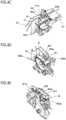
- FIGS. 4C to 4E are perspective views showing the example of the cutting unit of the present embodiment
- FIGS. 4F and 4G are plan views showing modified embodiments of the cutting unit of the present embodiment.
- the fixed blade part 60 is an example of the blade part, has a cylindrical shape serving as an axis of rotation of the movable blade part 61, and is provided with an opening 60a penetrating in a radial direction of the cylindrical shape along the feeding path of the wire W.
- the opening 60a has a shape through which the wire W can pass.
- a cross-sectional shape of the opening 60a is a long hole shape along a direction in which the two wires W are aligned in parallel.
- the opening 60a has, for example, a tapered shape in which opening areas on an introduction side and a discharge side of the opening 60a are widened with respect to the feeding of the wire W in the forward direction denoted with the arrow F.
- the fixed blade part 60 is provided on a downstream side of the wire guide 4 with respect to the feeding direction of the wire W that is conveyed in the forward direction.
- the fixed blade part 60 has a first butting portion 60b and a second butting portion 60c at an end portion of the opening 60a exposed on a circumferential surface on which the movable blade part 61 slides.
- the fixed blade part 60 is provided with a plurality of butting portions in a direction in which a plurality of wires W are aligned in parallel, and in the present example, is provided with the first butting portion 60b, which is one butting portion, and the second butting portion 60c, which is the other butting portion, along the direction in which the two wires W are aligned in parallel.
- the fixed blade part 60 is provided with the first butting portion 60b on a front side and the second butting portion 60c on an inner side, with respect to a moving direction of the movable blade part 61 denoted with an arrow D1.
- the fixed blade part 60 has a step portion 60d formed between the first butting portion 60b and the second butting portion 60c by recessing the second butting portion 60c with respect to the moving direction of the movable blade part 61 denoted with the arrow D1.
- a recessed amount is preferably about a half of the diameter of the wire W.
- the fixed blade part 60 has a regulation portion 60e configured to suppress the wire W butted against the first butting portion 60b from moving in a direction of the second butting portion 60c.
- the regulation portion 60e is a planar surface extending in a direction substantially orthogonal to the moving direction of the movable blade part 61 denoted with the arrow D1, and is provided between the first butting portion 60b and the step portion 60d.
- the movable blade part 61 is an example of the blade part, has a shape of sliding along the circumferential surface of the fixed blade part 60, and is configured to be in sliding contact with an open end of the opening 60a of the fixed blade part 60 by a rotating operation about the fixed blade part 60 serving as a fulcrum shaft.
- the cutting unit 6 has wall portions 62a and 62b configured to regulate introduction of foreign matters.
- the wall portions 62a and 62b are provided on upstream and downstream sides along a locus of the rotating operation of the movable blade part 61, with respect to the opening 60a of the fixed blade part 60.
- the wall portions 62a and 62b each have a shape following the locus of the rotating operation of the movable blade part 61 about the fixed blade part 60 serving as a fulcrum, and are configured to suppress foreign matters, such as wastes entering from an opening at a front end of the main body part 10 and shavings resulting from rubbing of the wire W and the reinforcing bar S, from entering the periphery of the movable blade part 61. Thereby, it is possible to suppress a malfunction of the movable blade part 61 and an increase in load for rotating the movable blade part 61.
- the wire W having passed through the opening 60a of the fixed blade part 60 is pressed against the open end of the opening 60a by the movable blade part 61.
- One wire W of the two wires W aligned in parallel is pressed against an end edge portion of the first butting portion 60b of the fixed blade part 60 by the operation of the movable blade part 61, and the other wire W is introduced into the second butting portion 60c of the fixed blade part 60.
- a shearing force is applied to one wire W, and cutting of the one wire W is started prior to the other wire W.
- the movable blade part 61 When the movable blade part 61 is rotated in the direction of the arrow D1 to start cutting of the first wire W, which is one wire, and the first wire W is cut to a predetermined position, the second wire W, which is the other wire, is pressed against an end edge portion of the second butting portion 60c of the fixed blade part 60 by the operation of the movable blade part 61.
- the shapes and positions of the first butting portion 60b and the second butting portion 60c are set so that, after starting the cutting of the first wire W, when the first wire W is cut in half or more in the radial direction, cutting of the second wire W is started. That is, a distance from the end edge portion of the first butting portion 60b to the end edge portion of the second butting portion 60c along the rotation direction of the movable blade part 61 denoted with the arrow D1 is set to be a substantial half of the wire W in the radial direction.
- the fixed blade part 60 has the regulation portion 60e formed between the first butting portion 60b and the second butting portion 60c and having a planar surface extending in a direction substantially orthogonal to the moving direction of the movable blade part 61 denoted with the arrow D1. Due to the planar surface, when the movable blade part 61 is moved in the direction of the arrow D1, it is possible to prevent an unintended force from acting on the wire W in the direction substantially orthogonal to the moving direction.
- the wire W butted against the first butting portion 60b by the movable blade part 61 is suppressed from moving to the direction of the second butting portion 60c.
- the wire W is suppressed from moving in the direction of the second butting portion 60c, so that wear of the step portion 60d is suppressed and a difference in distance from the end edge portion of the first butting portion 60b to the end edge portion of the second butting portion 60c along the rotation direction of the movable blade part 61 denoted with the arrow D1 is suppressed from decreasing. Therefore, it is possible to secure a phase difference of timings at which the cuttings of the two wires W are started, and to suppress an increase in load, which is caused when the cuttings of the two wires W are started at substantially the same time.
- the regulation portion 60e may be configured by providing the planar surface, which extends in the direction substantially orthogonal to the moving direction of the movable blade part 61 denoted with the arrow D1, at a part between the first butting portion 60b and the step portion 60d.
- the regulation portion 60e may be configured by an inclined surface or a curved surface where the step portion 60d protrudes from the first butting portion 60b toward the second butting portion 60c along a direction (arrow D2) opposite to the moving direction of the movable blade part 61 denoted with the arrow D1.
- the regulation portion 60e may be configured by a convex portion protruding from the first butting portion 60b and the second butting portion 60c along the direction (arrow D2) opposite to the moving direction of the movable blade part 61 denoted with the arrow D1, between the first butting portion 60b and the second butting portion 60c.
- the first butting portion 60b becomes a concave shape, so that the wire W butted against the first butting portion 60b by the movable blade part 61 is suppressed from moving in the direction of the second butting portion 60c.
- the regulation portion 60e may be formed into a shape of partitioning the first butting portion 60b and the second butting portion 60c therebetween.
- the first butting portion 60b and the second butting portion 60c are made independent, so that the wire W butted against the first butting portion 60b by the movable blade part 61 is suppressed from moving in the direction of the second butting portion 60c.
- the transmission unit 9 is supported so that the cam 90 can rotate about a shaft 90a as a fulcrum.
- the shaft 90a is attached to a frame 10a attached to an interior of the main body part 10.
- the frame 10a has a guide portion 10b configured to regulate a moving direction of a link 91.
- the guide portion 10b is configured by a long hole penetrating through the plate-shaped frame 10a.
- the cam 90 is an example of the displacement member, and has a cam groove 92 whose length from the shaft 90a is displaced.
- the cam groove 92 extends in radial and circumferential directions of the cam 90 about the shaft 90a, and intersects the guide portion 10b of the frame 10a.
- the cam groove 92 penetrates through the plate-shaped cam 90, so that an intersection of the cam groove 90 and the guide portion 10b communicates.
- the cam 90 is configured such that a rotating operation about the shaft 90a as a fulcrum changes a portion of the cam groove 92 intersecting the guide portion 10b, thereby changing a length from the shaft 90a to the intersection of the cam groove 92 and the guide portion 10b.
- ranges in which an amount of change in length between the shaft 90a and the cam groove 92 by the rotating operation about the shaft 90a as a fulcrum is large and small for the same amount of rotation of the cam 90 are set.
- a third range 92c in which there is little amount of change in length between the shaft 90a and the cam groove 92 are provided.
- the cam 90 is configured such that, while the first range 92a of the cam groove 92 intersects the guide portion 10b by the rotating operation in the direction of the arrow C1 about the shaft 90a as a fulcrum, the length from the shaft 90a to the intersection of the cam groove 92 and the guide portion 10b is shorter and the amount of change in length between the shaft 90a and the cam groove 92 becomes larger, as compared with a case where the second range 92b intersects the guide portion 10b.
- the cam 90 is configured such that, while the second range 92b of the cam groove 92 intersects the guide portion 10b by the rotating operation in the direction of the arrow C1 about the shaft 90a as a fulcrum, the length from the shaft 90a to the intersection of the cam groove 92 and the guide portion 10b is longer and the amount of change in length between the shaft 90a and the cam groove 92 becomes smaller, as compared with the case where the first range 92a intersects the guide portion 10b.
- the cam 90 is configured such that, while the third range 92c of the cam groove 92 intersects the guide portion 10b by the rotating operation in the direction of the arrow C1 about the shaft 90a as a fulcrum, the length from the shaft 90a to the intersection of the cam groove 92 and the guide portion 10b is substantially equivalent and the amount of change in length between the shaft 90a and the cam groove 92 is further smaller and substantially constant, as compared with the case where the second range 92b intersects the guide portion 10b.
- the cam 90 has an engaged portion 93 to which movement of the sleeve 71 is transmitted via the moving member 75.
- the engaged portion 93 is provided on an opposite side to the cam groove 92 with the shaft 90a interposed therebetween, and is arranged on a locus of the engaging portion 75a by the movement of the moving member 75 in conjunction with the movement of the sleeve 71 in the front and rear direction denoted with the arrows A1 and A2.
- the engaged portion 93 is engaged with the engaging portion 75a of the moving member 75 by an operation in which the sleeve 71 is moved in the forward direction denoted with the arrow A1.
- the cam 90 is urged by a spring 94 in the direction of the arrow C2 in which the first range 92a of the cam groove 92 intersects the guide portion 10b by the rotating operation about the shaft 90a as a fulcrum.
- the spring 94 is configured by, for example, a torsion coil spring attached to the shaft 90a. Note that, the rotation direction of the cam 90 denoted with the arrow C2 corresponds to a direction in which the movable blade part 61 connected by the link 91 returns from the cutting completion position to the initial position.
- the moving member 75 is provided with a pressing convex portion 76 and the cam 90 is provided with a pressed convex portion 96.
- the moving member 75 is moved in the direction of the arrow A1 direction and the cam 90 is rotated until the movable blade part 61 is rotated to the cutting completion position, the pressing convex portion 76 and the pressed convex portion 96 face.
- the pressing convex portion 76 pushes the pressed convex portion 96, so that the cam 90 can be forced to start rotating in the direction of the arrow C2.
- the link 91 is an example of the transmission member, and has an end portion in the forward direction denoted with the arrow A1 connected to the movable blade part 61, and an end portion in the backward direction denoted with the arrow A2 connected to the cam 90.
- the link 91 has a shaft portion 91a configured to enter the cam groove 92 of the cam 90 and the guide portion 10b of the frame 10a.
- the shaft portion 91a is configured by a rotary body 91a1 configured to enter the cam groove 92, and a shaft 91a2 configured to rotatably support the rotary body 91a1 and to be non-rotatable with respect to the link 91 that enters the guide portion 10b, and is inserted into the cam groove 92 and the guide portion 10b at the intersection of the cam groove 92 and the guide portion 10b.
- the shaft portion 91a is configured to move along the cam groove 92 and the guide portion 10b by the rotating operation of the cam 90 about the shaft 90a as a fulcrum.
- the shaft portion 91a may have a first rotary body configured to enter the cam groove 92, a second rotary body configured to enter the guide portion 10b, and a shaft configured to rotatably support the first rotary body and the second rotary body.
- the moving member 75 When the sleeve 71 is moved in the forward direction denoted with the arrow A1, the moving member 75 is moved in the forward direction denoted with the arrow A1 in conjunction with the sleeve 71.
- the moving member 75 is configured such that the engaging portion 75a is engaged with the engaged portion 93 of the cam 90 by the moving operation in the forward direction denoted with the arrow A1.
- the transmission unit 9 is configured such that, when the shaft portion 91a of the link 91 is moved in the direction away from the shaft 90a of the cam 90, the rotating operation of the cam 90 is converted into movement along the extension direction of the link 91.
- a period during which the first range 92a of the cam groove 92 intersects the guide portion 10b corresponds to a period after the movable blade part 61 of the cutting unit 6 starts rotation until the cutting of the first wire W is started.
- the period until the cutting of the first wire W is started corresponds to a region in which a load is low.
- a period during which the second range 92b of the cam groove 92 intersects the guide portion 10b corresponds to a period after the movable blade part 61 of the cutting unit 6 rotates and the cutting of the first wire W is started until the cutting of the second wire W ends.
- the period after the cutting of the first wire W is started until the cutting of the second wire W ends corresponds to a region in which a load is high.
- a period during which the third range 92c of the cam groove 92 intersects the guide portion 10b corresponds to a period during which the cutting of the second wire W ends and the rotation of the movable blade part 61 stops. In this way, with respect to the amount of movement of the moving member 75, it is not necessary to rotate the cutter having completed the wire cutting operation more than necessary.
- the cam 90 has such a configuration that the length from the intersection of the cam groove 92, which is a first connection portion connected to the link 91, and the guide portion 10b to the shaft 90a is switched by the rotating operation about the shaft 90a as a fulcrum due to the shape of the cam groove 92.
- the cam 90 makes it possible to switch the amount of rotation (amount of movement) of the movable blade part 61 and the force that can be generated by the movable blade part 61, within the rotating range (moving range) of the movable blade part 61.
- the cam 90 may be configured such that a length from the engaged portion 93, which is a second connection portion connected to the sleeve 71, to the shaft 90a is switched by the rotating operation about the shaft 90a as a fulcrum.
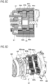
- FIG. 5A is a side cross-sectional view showing an example of the decelerator of the present embodiment
- FIG. 5B is a perspective view showing the example of the decelerator of the present embodiment
- Fig.5C is a side cross-sectional view of main parts showing a modified embodiment of the decelerator of the present embodiment
- FIG. 5D is a perspective view showing the modified embodiment of the decelerator of the present embodiment.
- the decelerator 81 is configured by a planet gear in which an input shaft and an output shaft are coaxially arrayed, and includes a first sun gear 82a attached to a shaft 80a of a motor 80 serving as an input shaft, a first planetary gear 83a in mesh with the first sun gear 82a and a first planet cage 84a configured to support the first planetary gear 83a.
- the decelerator 81 includes a second sun gear 82b provided to the first planet cage 84a, a second planetary gear 83b in mesh with the second sun gear 82b, and a second planet cage 84b configured to support the second planetary gear 83b.
- the decelerator 81 includes an internal gear 85 in mesh with the first planetary gear 83a and the second planetary gear 83b.
- the internal gear 85 is fixed to the main body part 10.
- the first planet cage 84a and the second planet cage 84b are arranged coaxially with the shaft 80a of the motor 80.
- the second planet cage 84b is connected to the rotary shaft 72, and configures an output shaft.
- the front side portion 84f protruding from the internal gear 85 is rotatably supported by the main body part 10 via a bearing 86.
- a rear side portion 84r that is the other side along the axis direction is located inside the internal gear 85, and the rear side portion 84r is supported to the internal gear 85 by a support member 87. Since the internal gear 85 is fixed to the main body part 10, the rear side portion 84r of the second planet cage 84b is supported by the main body part 10 via the support member 87 configuring a sliding bearing and the internal gear 85. Note that, the support member 87 may be configured by a bearing.
- the decelerator 81 includes a gear holder 88 between the first planet cage 84a and the second planetary gear 83b.
- the gear holder 88 is configured by a disk-shaped member having a hole perforated at a center into which the second sun gear 82b is inserted, and is inserted between the first planet cage 84a and the second planetary gear 83b outside the second sun gear 82b, thereby securing a gap between the first planet cage 84a and the second planetary gear 83b.
- the second planet cage 84b is supported at the front side portion 84f and the rear side portion 84r along the axis direction by the main body part 10. Therefore, with a simple configuration, the second planet cage 84b is suppressed from being inclined with respect to the axis direction, and changes in meshes between the sun gear and the planetary gear and between the planetary gear and the internal gear, and interferences between gears aligned in parallel in the axis direction, between a gear and a planet cage, and the like are suppressed.
- the gear holder 88a may be provided integrally with the first planet cage 84a.
- the gear holder 88a is configured such that a disk-shaped member having a hole perforated at a center into which the second sun gear 82b is inserted is provided integrally with the first planet cage 84a outside the second sun gear 82b.
- the gear holder 88a is inserted between the first planet cage 84a and the second planetary gear 83b outside the second sun gear 82b, thereby securing a gap between the first planet cage 84a and the second planetary gear 83b.
- FIGS. 6A to 6D are plan views showing an example of the curl forming unit of the present embodiment. Next, an example of the curl forming unit of the present embodiment will be described with reference to each drawing.
- the curl forming unit 5 includes a guide groove 52 configuring a feeding path of the wire W in the curl forming unit 5, and a first guide member 53a and a second guide member 53b, which are configured to curl the wire W in cooperation with the guide groove 52.
- the first guide member 53a is provided on an introduction part side of the curl guide 50 for the wire W that is fed in the forward direction by the wire feeding unit 3, and is arranged on a radially inner side of the loop Ru formed by the wire W with respect to the feeding path of the wire W by the guide groove 52.
- the first guide member 53a is configured to regulate the feeding path of the wire W so that the wire W fed along the guide groove 52 does not enter the radially inner side of the loop Ru formed by the wire W.
- the second guide member 53b is provided on a discharge part side of the curl guide 50 for the wire W that is fed in the forward direction by the wire feeding unit 3, and is arranged on a radially outer side of the loop Ru formed by the wire W with respect to the feeding path of the wire W by the guide groove 52.
- the curl forming unit 5 includes a retraction mechanism 54 configured to retract the first guide member 53a from the feeding path of the wire W.
- the retraction mechanism 54 is attached to a frame 55 for fixing the curl guide 50 to the main body part 10 so as to be rotatable about a shaft 54a as a fulcrum, and is configured to be displaced in directions in which the first guide member 53a protrudes and retracts with respect to the feeding path of the wire W.
- the retraction mechanism 54 is urged by an urging member 56 such as a spring, in the direction in which the first guide member 53a protrudes to the feeding path of the wire W.
- the retraction mechanism 54 includes an induction part 57 configured to displace the retraction mechanism 54 in the direction in which the first guide member 53a retracts with respect to the feeding path of the wire W.
- the induction part 57 is configured by an inclined surface configured, in an operation of winding the wire W on the reinforcing bars S, to be pushed by the wire W, thereby generating a force for displacing the retraction mechanism 54 in the direction in which the first guide member 53a retracts with respect to the feeding path of the wire W.
- the retraction mechanism 54 includes a wire guide part 58 configuring a part of the guide groove 52.
- the wire guide part 58 protrudes to the feeding path of the wire W, and configures a part of the guide groove 52.
- the wire guide part 58 protrudes to the feeding path of the wire W, and closes a path along which the wire W is exposed to an outside of the guide groove 52.
- the curl forming unit 5 includes a feeding regulation part 59 against which a tip end of the wire W is butted, on the feeding path of the wire W that is curled by the curl guide 50 and guided to the binding unit 7 by the induction guide 51.
- the retraction mechanism 54 includes an opening/closing regulation portion 54b configured to engage with the moving member 75 configured to move in conjunction with the sleeve 71 and to be in contact with an opening/closing regulation member 55a configured to operate in conjunction with the moving member 75.
- the opening/closing regulation portion 54b comes in contact with the opening/closing regulation member 55a in a state in which the retraction mechanism 54 has moved in the direction in which the first guide member 53a protrudes to the feeding path of the wire W, so that the rotation of the retraction mechanism 54 about the shaft 54a as a fulcrum is regulated.
- the opening/closing regulation member 55a when the opening/closing regulation member 55a is moved in conjunction with the operation of the binding unit 7 for locking the wire W with the locking member 70, and an opening portion 55b of the opening/closing regulation member 55a is moved to a position where it faces the opening/closing regulation portion 54b of the retraction mechanism 54, the opening/closing regulation portion 54b enters the opening portion 55b, so that the regulation of rotation of the retraction mechanism 54 about the shaft 54a as a fulcrum is released.
- the retraction mechanism 54 can be moved by the rotating operation about the shaft 54a as a fulcrum, in the direction in which the first guide member 53a retracts with respect to the feeding path of the wire W.
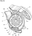
- FIG. 7A is a front view showing an example of a magazine according to the present embodiment
- FIG. 7B is a perspective view showing the example of the magazine according to the present embodiment
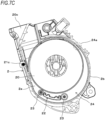
- FIG. 7C is a front cross-sectional view showing the example of the magazine of the present embodiment
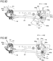
- FIG. 7D is a side cross-sectional view showing the example of the magazine according to the present embodiment.
- the magazine 2 has such a form that a peripheral wall portion 2b is erected around a side wall portion 2a, and a surface on an opposite side to the side wall portion 2a is opened.
- the magazine 2 has an openable/closable cover part 21.
- the cover part 21 is configured to open/close an opening of the magazine 2 by a rotating operation about a hinge portion 21a as a fulcrum provided to the peripheral wall portion 2b.As for the magazine 2, the reel 20 can be attached and detached by opening the cover part 21.
- the magazine 2 has a separation part 22 between an accommodation position 20a of the reel 20 shown by the dashed-two dotted line and a feeding path 20b of the wire W in the magazine 2 shown by the broken line.
- the separation part 22 protrudes from the side wall portion 2a of the magazine 2 along the peripheral wall portion 2b in an axis line direction of the reel 20.
- the separation part 22 is provided on an opposite side to a delivery port 20c from which the wire W is delivered, with respect to the accommodation position 20a of the reel 20.
- the opposite side to the delivery port 20c is a range in which the wire W is likely to be bent during the operation of feeding the wire W in the reverse direction denoted with the arrow R and the bent wire W is likely to be displaced toward the wire W wound on the reel 20 during a next operation of feeding the wire W in the forward direction denoted with the arrow F.
- the separation part 22 is configured to separate the reel 20 accommodated in the magazine 2 and the feeding path 20b of the wire W in the range in which the bent wire W is likely to come close to the reel 20 during the operation of feeding the wire W in the forward direction denoted with the arrow F.
- the separation part 22 has rotation members 23 provided at end portions on upstream and downstream sides with respect to the feeding direction of the wire W.
- the rotation member 23 is provided such that a shaft of rotation extends in a direction intersecting the feeding direction of the wire W and the rotation member can rotate as a result of contact with the wire W fed in the forward or reverse direction.
- the separation part 22 includes a holding member 22a configured to rotatably support the rotation member 23.
- the holding member 22a is attached to a site of the separation part 22 on an opposite side to the side wall portion 2a.As for the rotation member 23, one side along the axis direction is rotatably supported by the side wall portion 2a, and the other side along the axis direction is rotatably supported by the holding member 22a.
- the separation part 22 has a support concave portion 22b that is supported by the cover part 21.
- the cover part 21 has a support convex portion 21b configured to support the separation part 22.
- the support concave portion 22b is an example of the support portion, and is configured by providing the holding member 22a, which faces the closed cover part 21, with a concave portion having a predetermined shape.
- the support convex portion 21b is an example of the support portion, and is configured by providing a convex portion having a predetermined shape that is fitted into the support concave portion 22b of the separation part 22 so as to be insertable/removable when the cover part 21 is closed.
- the separation part 22 is provided with the support convex portion and the cover part 21 is provided with the support concave portion. Further, a configuration is also possible in which the separation part 22 is provided with a support convex portion and a support concave portion and the cover part 21 is provided with a support concave portion and a support convex portion, correspondingly to the support convex portion and the support concave portion of the separation part 22.
- the magazine 2 has an escape part 24 for the wire W on an upstream side of the separation part 22 with respect to the feeding direction of the wire W in the forward direction denoted with the arrow F.
- the escape part 24 is configured by providing a space, in which the wire W can be bent during an operation of feeding the wire W in the reverse direction denoted with the arrow R, between the reel 20 accommodated at the accommodation position 20a and the peripheral wall portion 2b with a predetermined length between an outer periphery position of the accommodation position 20a of the reel 20 and the peripheral wall portion 2b.
- the length of the escape part 24 from the outer periphery position of the accommodation position 20a of the reel 20 gradually expands along the feeding direction of the wire W in the forward direction denoted with the arrow F, and a starting point position 24a of a wall portion of the escape part 24 is connected to the peripheral wall portion 2b by an arc.
- the magazine 2 has a buckling regulation portion 21c on the feeding path 20b of the wire W.
- the buckling regulation portion 21c is provided to the cover part 21, and is exposed to the feeding path 20b of the wire W between the outer periphery of the accommodation position 20a and the delivery port 20c when the cover part 21 is closed.
- the buckling regulation portion 21c is configured by a column-shaped or cylindrical member, a roller or the like made of a material with a low coefficient of friction, and is configured to suppress a resistance of feeding due to friction mainly when the wire W fed in the reverse direction denoted with the arrow R is contacted, thereby suppressing the wire W from buckling.
- the magazine 2 has a guide wall portion 2c at the delivery port 20c.
- the guide wall portion 2c is configured by providing, on a rear side of the delivery port 20c, a planar surface connected to the peripheral wall portion 2b and erected along the feeding direction of the wire W.
- the magazine 2 has an intrusion regulation concave portion 2d and an intrusion regulation convex portion 21d configured to regulate introduction of the wire W between the cover part 21 and the peripheral wall portion 2b.
- the intrusion regulation concave portion 2d is an example of the intrusion regulation portion, and is configured by providing the peripheral wall portion 2b, which faces the closed cover part 21, with a concave portion having a predetermined.
- the intrusion regulation convex portion 21d is an example of the intrusion regulation portion, and is configured by providing a convex portion having a predetermined shape that is fitted into the intrusion regulation concave portion 2d of the peripheral wall portion 2b so as to be insertable/removable when the cover part 21 is closed.
- peripheral wall portion 2b is provided with the intrusion regulation convex portion and the cover part 21 is provided with the intrusion regulation concave portion.
- peripheral wall portion 2b is provided with an intrusion regulation convex portion and an intrusion regulation concave portion and the cover part 21 is provided with an intrusion regulation concave portion and an intrusion regulation convex portion, correspondingly to the intrusion regulation convex portion and the intrusion regulation concave portion of the peripheral wall portion 2b.
- the separation part 22 has a guide convex portion 22c configured to regulate introduction of the wire W between the holding member 22b and the rotation member 23.
- the guide convex portion 22c is provided corresponding to the rotation member 23 located on an upstream side with respect to the feeding direction of the wire W in the forward direction denoted with the arrow F, and is configured by providing a convex portion protruding from the holding member 22b along a circumferential surface of the rotation member 23 in the vicinity of one end portion of the rotation member 23 in the axis direction.
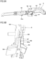
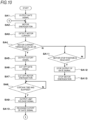
- FIG. 8A is a block diagram showing an example of a control function of the reinforcing bar binding machine.
- the control unit 14 in response to a state of the operation switch 13 pressed by an operation on the trigger 12 shown in FIG. 1 , the control unit 14 is configured to control the motor 80 and a feeding motor 31, thereby executing a series of operations of binding the reinforcing bars S with the wire W.
- a voltage (battery voltage) of the battery 15 decreases with the execution of the operation of binding the reinforcing bars S with the wire W. For this reason, immediately after the battery 15 is charged, the number of rotations (rotating speed) of the motor 80 or the like becomes relatively high, and as the binding operation is executed, the voltage decreases, so that the number of rotations (rotating speed) of the motor 80 or the like becomes relatively low.
- the reinforcing bar binding machine 1A is configured to control the motor 80 and the feeding motor 31, in response to the voltage (battery voltage) of the battery 15, thereby shortening the time required for the series of operations of binding the reinforcing bars S with the wire W while suppressing an increase in load or heat generation, and smoothing the time regardless of an increase or decrease in battery voltage.
- the reinforcing bar binding machine 1A is configured to implement a control of limiting a current flowing through the motor 80 and the feeding motor 31 by hardware or software, as an example of the control on the motor 80 and the feeding motor 31 corresponding to the battery voltage.
- FIG. 8B is a block diagram showing an example of a configuration in which a function of limiting a current flowing through a motor is implemented by hardware.
- the control unit 14 includes a limiting circuit 100 configured to cut off and restore energization to the motor 80 and the feeding motor 31, in response to the battery voltage.
- control unit 14 includes a microcomputer 101 configured to control the motor 80 and the feeding motor 31, and a motor driver 102 configured, in response to the control of the microcomputer 101, to cause the current to flow from the battery 15 to the motor 80 and the feeding motor 31 to drive the motor 80 and the feeding motor 31.
- the motor 80 and the feeding motor 31 are controlled and driven by the independent limiting circuits 100 and motor drivers 102.
- the microcomputer 101 is configured to output a gate signal Sg1 at a predetermined timing for driving the motor 80 and the feeding motor 31.
- the motor driver 102 configured to drive the motor 80 causes the current to flow from the battery 15 to the motor 80.
- the motor driver 102 configured to drive the feeding motor 31 causes the current to flow from the battery 15 to the feeding motor 31.
- the limiting circuit 100 includes a current detection circuit 103 configured to detect the battery voltage by the current flowing through the motor 80 and the feeding motor 31.
- the current detection circuit 103 includes a shunt resistor 103a and a differential amplifier (operational amplifier) 103b so as to convert the current flowing through the motor 80 and the feeding motor 31 into a voltage.
- the limiting circuit 100 corresponding to the motor 80 and the limiting circuit 100 corresponding to the feeding motor 31 are each provided with a comparator unit 104 configured to output a signal (cutoff signal) Sg2 for cutting off the current flowing through the motor 80 and the feeding motor 31, in response to a difference between a current (motor current value) Va flowing through the motor 80 and a motor current value Va flowing through the feeding motor 31 and a threshold value (current limit threshold value) Vr serving as a reference for determining whether it is necessary to control the current.
- a comparator unit 104 configured to output a signal (cutoff signal) Sg2 for cutting off the current flowing through the motor 80 and the feeding motor 31, in response to a difference between a current (motor current value) Va flowing through the motor 80 and a motor current value Va flowing through the feeding motor 31 and a threshold value (current limit threshold value) Vr serving as a reference for determining whether it is necessary to control the current.
- the limiting circuit 100 includes a gate driver 105 configured to switch whether or not to drive the motor 80 and the feeding motor 31 by the motor driver 102, in response to an output of the comparator unit 104.
- the comparator unit 104 is input with the motor current value Va flowing through the motor 80 and detected by the current detection circuit 103 and the current limit threshold value Vr generated by a threshold value generation unit 104a, and outputs the cutoff signal Sg2 when the motor current value Va flowing through the motor 80 becomes equal to or greater than the current limit threshold value Vr.
- the comparator unit 104 is input with the motor current value Va flowing through the feeding motor 31 and detected by the current detection circuit 103 and the current limit threshold value Vr generated by the threshold value generation unit 104a, and outputs the cutoff signal Sg2 when the motor current value Va flowing through the feeding motor 31 becomes equal to or greater than the current limit threshold value Vr.
- a voltage drop of a resistor is converted into a current value for current detection, and the comparator unit 104 compares the motor current value Va and the current limit threshold value Vr by a magnitude of the voltage, which is equivalent to detecting the current.
- the gate driver 105 is provided between the microcomputer 101 and the motor driver 102, and inputs, to the motor driver 102, the gate signal Sg1 output from the microcomputer 101 when the cutoff signal Sg2 is not input from the comparator unit 104.
- the current flows from the battery 15 to the motor 80, and the motor 80 rotates at the number of rotations (rotating speed) corresponding to the battery voltage.
- the current flows from the battery 15 to the feeding motor 31, and the feeding motor 31 rotates at the number of rotations (rotating speed) corresponding to the battery voltage.
- the gate driver 105 cuts off the gate signal Sg1 output from the microcomputer 101, and does not input the gate signal to the motor driver 102.
- the motor driver 102 cuts off the current flowing from the battery 15 to the motor 80 and the feeding motor 31 because the gate signal Sg1 is not input.
- the limiting circuit 100 corresponding to the motor 80 the current flowing from the battery 15 to the motor 80 is cut off, and the motor 80 rotates through inertia. In this case, as compared with the case of driving with the battery voltage, the number of rotations (rotating speed) of the motor 80 decreases. In addition, in the limiting circuit 100 corresponding to the feeding motor 31, the current flowing from the battery 15 to the feeding motor 31 is cut off, and the feeding motor 31 rotates through inertia. In this case, as compared with the case of driving with the battery voltage, the number of rotations (rotating speed) of the feeding motor 31 decreases.
- the comparator unit 104 stops the output of the cutoff signal Sg2 when a limit release signal Sg3 is input from the microcomputer 101. Note that, the comparator unit 104 may stop the output of the cutoff signal Sg2 when the motor current value Va flowing through the feeding motor 31 becomes less than the current limit threshold value Vr.
- the gate driver 105 releases the cutoff of the gate signal Sg1 output from the microcomputer 101, and inputs the gate signal Sg1 to the motor driver 102.
- the current flows from the battery 15 to the motor 80, and the motor 80 rotates at the number of rotations (rotating speed) corresponding to the battery voltage.
- the current flows from the battery 15 to the feeding motor 31, and the feeding motor 31 rotates at the number of rotations (rotating speed) corresponding to the battery voltage.
- the limiting circuit 100 includes a parallel resistor 106 for limit value variation for changing a reference for determining whether it is necessary to limit the current flowing through the motor 80 and the feeding motor 31.
- the parallel resistor 106 for limit value variation is provided between an output of the current detection circuit 103 and an input of the comparator unit 104, and a resistance value is made variable by a limit value control signal Sg4 from the microcomputer 101, so that the high and low of the voltage to be input to the comparator unit 104 is switched.
- the high and low of the current limit threshold value Vr changes relatively with respect to the motor current value Va input to the comparator unit 104, the reference for determining whether it is necessary to limit the current flowing through the motor 80 and the feeding motor 31 changes, and the current limit threshold value can lowered so that a current value for limiting becomes high or the current limit threshold value can be increased so that the current value for limiting becomes low.
- the parallel resistor 106 for limit value variation may be provided between the threshold value generation unit 104a and the input of the comparator unit 104, and the high and low of the current limit threshold value Vr may be changed.
- the above-described constitutional elements of the control unit 14 are configured by a single integrated circuit or a plurality of integrated circuits, which is mounted on a substrate.
- the limiting circuit 100 configured to limit the current flowing through the motor 80 and the feeding motor 31, as an example of the control on the motor 80 and the feeding motor 31 corresponding to the battery voltage, is configured as hardware.
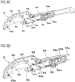
- FIG. 8C is a block diagram showing an example of a configuration in which the function of limiting the current flowing through the motor is implemented by software.
- the control unit 14 includes a microcomputer 101 configured to control the motor 80 and the feeding motor 31, in response to the battery voltage, and a motor driver 102 configured, in response to the control of the microcomputer 101, to cause the current to flow from the battery 15 to the motor 80 and the feeding motor 31 to drive the motor 80 and the feeding motor 31.
- the microcomputer 101 is configured to output a gate signal Sg1 at a predetermined timing for driving the motor 80 and the feeding motor 31.
- the motor driver 102 configured to drive the motor 80 causes the current to flow from the battery 15 to the motor 80.
- the motor driver 102 configured to drive the feeding motor 31 causes the current to flow from the battery 15 to the feeding motor 31.
- the control unit 14 includes a current detection circuit 103 configured to detect the battery voltage by the current flowing through the motor 80 and the feeding motor 31.
- the current detection circuit 103 includes a resistor (shunt resistor) 103a configured to drop a voltage and a differential amplifier (operational amplifier) 103b configured to amplify a voltage corresponding to the drop, so as to convert the current flowing through the motor 80 and the feeding motor 31 into a voltage.
- control unit 14 includes a gate driver 105 configured to switch whether or not to drive the motor 80 and the feeding motor 31 by the motor driver 102, in response to an output of the microcomputer 101.
- the microcomputer 101 is configured to acquire a current (motor current value) Va flowing through the motor 80 at a timing of driving the motor 80, and a motor current value Va flowing through the feeding motor 31 at a timing of driving the feeding motor 31, and outputs a cutoff signal Sg2 for cutting off the current flowing through the motor 80 and the feeding motor 31 when the motor current value Va becomes equal to or greater than a threshold value serving as a reference for determining whether it is necessary to control the current.
- the microcomputer 101 outputs a limit release signal Sg3 instead of the cutoff signal Sg2 when the motor current value Va becomes less than the threshold value serving as a reference for determining whether it is necessary to control the current.
- the control unit 14 may output the limit release signal Sg3 when a time has elapsed from an output of the cutoff signal Sg2.
- the gate driver 105 is provided between the microcomputer 101 and the motor driver 102, and inputs, to the motor driver 102, the gate signal Sg1 output from the microcomputer 101 when the cutoff signal Sg2 is not input from the microcomputer 101.
- the current flows from the battery 15 to the motor 80, and the motor 80 rotates at the number of rotations (rotating speed) corresponding to the battery voltage.
- the current flows from the battery 15 to the feeding motor 31, and the feeding motor 31 rotates at the number of rotations (rotating speed) corresponding to the battery voltage.
- the gate driver 105 cuts off the gate signal Sg1 output from the microcomputer 101, and does not input the gate signal to the motor driver 102.
- the motor driver 102 cuts off the current flowing from the battery 15 to the motor 80 and the feeding motor 31 because the gate signal Sg1 is not input.
- the limiting circuit 100 corresponding to the motor 80 the current flowing from the battery 15 to the motor 80 is cut off, and the motor 80 rotates through inertia. In this case, as compared with the case of driving with the battery voltage, the number of rotations (rotating speed) of the motor 80 decreases. In addition, in the limiting circuit 100 corresponding to the feeding motor 31, the current flowing from the battery 15 to the feeding motor 31 is cut off, and the feeding motor 31 rotates through inertia. In this case, as compared with the case of driving with the battery voltage, the number of rotations (rotating speed) of the feeding motor 31 decreases.
- the gate driver 105 releases the cutoff of the gate signal Sg1 output from the microcomputer 101 and inputs the gate signal Sg1 to the motor driver 102.
- the current flows from the battery 15 to the motor 80, and the motor 80 rotates at the number of rotations (rotating speed) corresponding to the battery voltage.
- the current flows from the battery 15 to the feeding motor 31, and the feeding motor 31 rotates at the number of rotations (rotating speed) corresponding to the battery voltage.
- the motor current value Va becomes equal to or greater than the current threshold value
- the current flowing through the motor 80 and the feeding motor 31 is cut off, so that a control of, when the battery voltage becomes equal to or greater than a predetermined threshold value, limiting the current flowing through the motor 80 and the feeding motor 31 to temporarily lower the number of rotations (rotating speed) is performed.
- the control unit 14 is configured to implement a control of limiting the current flowing through the motor 80 and the feeding motor 31 by software, in response to the motor current value Va, as an example of the control on the motor 80 and the feeding motor 31 corresponding to the battery voltage.
- the reinforcing bar binding machine 1A is in a standby state where the wire W is sandwiched between the pair of feeding gears 30 and the tip end of the wire W is located between a sandwiched position by the feeding gears 30 and the fixed blade part 60 of the cutting unit 6. Also, when the reinforcing bar binding machine 1A is in the standby state, the sleeve 71 and the first side hook 70R, the second side hook 70L and the center hook 70C attached to the sleeve 71 are moved in the rear direction denoted with the arrow A2, and as shown in FIG. 3A , the first side hook 70R is opened with respect to the center hook 70C, and the second side hook 70L is opened with respect to the center hook 70C.
- the feeding motor (not shown) is driven in the forward rotation direction, so that the wire W is fed in the forward direction denoted with the arrow F by the wire feeding unit 3A.
- the two wires W are fed aligned in parallel along an axis direction of the loop Ru, which is formed by the wires W, by the wire guide 4.
- the wire W fed in the forward direction passes between the center hook 70C and the first side hook 70R, and is then fed to the curl guide 50 of the curl forming unit 5.
- the wire W passes through the curl guide 50 and is thus curled to be wound around the reinforcing bars S.
- the wire W curled by the curl guide 50 is guided to the induction guide 51 and is further fed in the forward direction by the wire feeding unit 3A, so that the wire is guided between the center hook 70C and the second side hook 70L by the induction guide 51. Then, the wire W is fed until the tip end is butted against the feeding regulation part 59. When the wire W is fed to a position at which the tip end is butted against the feeding regulation part 59, the drive of the feeding motor (not shown) is stopped.
- the motor 80 After stopping the feeding of the wire W in the forward direction, the motor 80 is driven in the forward rotation direction.
- the rotation regulation blade 74a In the first operation area where the wire W is locked by the locking member 70, the rotation regulation blade 74a is locked, so that the rotation of the sleeve 71 in conjunction with the rotation of the rotary shaft 72 is regulated. Thereby, the rotation of the motor 80 is converted into linear movement, so that the sleeve 71 is moved in the forward direction denoted with the arrow A1.
- the first side hook 70R and the second side hook 70L of the locking member 70 are moved toward the center hook 70C by the rotating operations about the shaft 71b as a fulcrum, due to the locus of the opening/closing pin 71a and the shape of the opening/closing guide holes 73R and 73L.
- the inner wall surface of the first side hook 70R with respect to the direction in which the first side hook 70R is closed is pushed by the opening/closing pin 71a, in the opening/closing portion 73a formed in the opening/closing guide hole 73R.
- the first side hook 70R is rotated about the shaft 71b as a fulcrum and is moved toward the center hook 70C.
- first side hook 70R and the second side hook 70L are closed with respect to the center hook 70C.
- the wire W sandwiched between the second side hook 70L and the center hook 70C is locked in such a manner that the wire cannot come off between the second side hook 70L and the center hook 70C, within the range in which the opening/closing pin 71a is located at the locking portion 73b of the opening/closing guide hole 73L, as shown in FIG. 3B .
- the pair of feeding gears 30 is reversely rotated and the wire W sandwiched between the pair of feeding gears 30 is fed in the reverse direction denoted with the arrow R. Since the tip end side of the wire W is locked in such a manner that the wire does not come off between the second side hook 70L and the center hook 70C, the wire W is wound on the reinforcing bars S by the operation of feeding the wire W in the reverse direction.
- the induction part 57 of the retraction mechanism 54 is pushed by the wire W, so that the first guide member 53a retracts with respect to the feeding path of the wire W.
- the reel 20 rotates in accordance with the feeding of the wire W during the operation of feeding the wire W in the forward direction denoted with the arrow F.
- the reel 20 rotates in accordance with the feeding of the wire W in a state in which a force of winding the wire W on the reel 20 is applied by sliding resistance of the magazine 2 and the reel 20.
- the reel 20 slightly continues to rotate due to its inertia, so that the wire W wound on the reel 20 loosens and expands in the radial direction of the reel 20.
- the reel 20 rotates while being pushed by the wire W, but the rotation of the reel 20 is delayed with respect to a feeding speed of the wire W by the wire feeding unit 3.
- the magazine 2 has the separation part 22 between the accommodation position 20a and the feeding path 20b of the wire W on the opposite side to the delivery port 20c of the magazine 2 from which the wire W is delivered.
- the separation part 22 separates the reel 20 accommodated in the magazine 2 and the feeding path 20b of the wire W in the range in which the bent wire W is likely to come close to the reel 20 during the operation of feeding the wire W in the forward direction denoted with the arrow F.
- the wire W which has been fed in the reverse direction and bent, is suppressed from being displaced toward the reel 20 during the next operation of feeding the wire in the forward direction, so that the wire W pulled out from the reel 20 is suppressed from being entangled with the wire W wound on the reel 20.
- the separation part 22 has the rotation members 23 at the end portions on the upstream and downstream sides with respect to the feeding direction of the wire W, so that the wire W that is mainly fed in the forward direction comes into contact with the rotation members 23, and therefore, the rotation members 23 rotate. Thereby, the sliding resistance at the time when the wire W slides with respect to the separation member 22 is reduced.
- the magazine 2 has the escape part 24 for the wire W on the upstream side of the separation part 22 with respect to the feeding direction of the wire W in the forward direction denoted with the arrow F, so that the space in which the wire W fed in the reverse direction denoted with the arrow R can be bent on the upstream side of the separation part 22 is secured.
- the wire W fed in the reverse direction can be bent in a direction away from the reel 20, and the wire W pulled out from the reel 20 is suppressed from being entangled with the wire W wound on the reel 20.
- the escape part 24 on the upstream side of the separation part 22 a space is secured between the reel 20 and the peripheral wall portion 2b of the magazine 2, and the wire W fed in the reverse direction is suppressed from colliding with the peripheral wall portion 2b of the magazine 2.
- the holding member 22b is provided with the guide convex portion 22c protruding along the circumferential surface of the rotation member 23 in the vicinity of one end portion of the rotation member 23 in the axis direction.
- the wire W in contact with the rotation member 23 moves in the axis direction of the rotation member 23 and is introduced between the holding member 22b and the rotation member 23.
- the magazine 2 is configured such that, when the cover part 21 is closed, the support convex portion 21b of the cover part 21 is fitted into the support concave portion 22b of the separation part 22, whereby the cover part 21 side of the separation part 22 is supported by the closed cover part 21. Thereby, even when a force is applied to the separation part 22 by the wire W, deformation of the separation part 22 is suppressed.
- the motor 80 is driven in the forward rotation direction, so that the sleeve 71 is further moved in the forward direction denoted with the arrow A1.
- FIGS. 9A to 9G are operation explanatory diagrams showing an example of the operations of the binding unit, the transmission unit and the cutting unit according to the present embodiment.
- FIG. 9A when the sleeve 71 is moved in the forward direction denoted with the arrow A1, the moving member 75 is moved in the forward direction denoted with the arrow A1 in conjunction with the sleeve 71.
- the engaging portion 75a is engaged with the engaged portion 93 of the cam 90 by the operation of the moving member 75 moving in the forward direction denoted with the arrow A1.
- a region from when the sleeve 71 is moved in the forward direction denoted with the arrow A1 until the engaging portion 75a of the moving member 75 is engaged with the engaged portion 93 of the cam 90 is referred to as an idle running region.
- the shaft portion 91a is inserted into the cam groove 92 and the guide portion 10b at the intersection of the cam groove 92 and the guide portion 10b, and the rotating operation of the cam 90 about the shaft 90a as a fulcrum moves the shaft portion 91a along the cam groove 92 and the guide portion 10b.
- the idle running region and the idling region are regions in which a load that is applied to the movable blade part 61 is low.
- the first range 92a of the cam groove 92 intersects the guide portion 10b. While the first range 92a of the cam groove 92 intersects the guide portion 10b, the length from the shaft 90a to the intersection of the cam groove 92 and the guide portion 10b is shorter and the amount of change in length between the shaft 90a and the cam groove 92 becomes larger, as compared with the case where the second range 92b intersects the guide portion 10b.
- the amount of rotation of the movable blade part 61 becomes relatively large with respect to the amount of movement of the sleeve 71 that rotates the cam 90.
- the cutting of the wire W since the cutting of the wire W has not been started, there is no wire cutting load that is applied to the movable blade part 61, so that an increase in load that is applied to the cam 90 connected to the movable blade part 61 via the link 91 is suppressed.
- the cam 90 Since the cam 90 is connected to the sleeve 71 via the moving member 75, the increase in load that is applied to the cam 90 is suppressed, so that an increase in load that is applied to the rotary shaft 72 that moves the sleeve 71 and to the motor 80 connected to the rotary shaft 72 via the decelerator 81 is suppressed.
- a time consumed to rotate the movable blade part 61 to a position where the cutting of the wire W is started can be shortened by relatively increasing the amount of rotation of the movable blade part 61.
- the cam 90 rotates about the shaft 90a as a fulcrum, as shown in FIG. 9D , so that the second range 92b of the cam groove 92 intersects the guide portion 10b.
- the moving member 75 is further moved in the forward direction denoted with the arrow A1 to rotate the cam 90 in the direction of the arrow C1, and the rotating operation of the cam 90 is transmitted to the movable blade part 61 via the link 91, so that the movable blade part 61 is further rotated in the direction of the arrow D1 to start cutting of the first wire W.
- the movable blade part 61 After the movable blade part 61 is rotated in the direction of the arrow D1 to start cutting of the first wire W, which is one wire, when the first wire W is cut to a predetermined position, the second wire W, which is the other wire, is pressed against the end edge portion of the second butting portion 60c of the fixed blade part 60 by the operation of the movable blade part 61.
- the length from the shaft 90a to the intersection of the cam groove 92 and the guide portion 10b is longer and the amount of change in length between the shaft 90a and the cam groove 92 becomes smaller, as compared with the case where the first range 92a intersects the guide portion 10b.
- the amount of rotation of the movable blade part 61 becomes relatively small with respect to the amount of movement of the sleeve 71.
- the increase in load that is applied to the cam 90 is suppressed, so that an increase in load that is applied to the rotary shaft 72 that moves the sleeve 71 and to the motor 80 connected to the rotary shaft 72 via the decelerator 81 is suppressed.
- the load that is applied to the movable blade part 61 further increases.
- the force that can be generated by the movable blade part 61 increases, so that the load that is applied to the movable blade part 61 is canceled and the increase in load that is applied to the cam 90 connected to the movable blade part 61 via the link 91 is suppressed.
- the increase in load that is applied to the cam 90 is suppressed, so that an increase in load that is applied to the rotary shaft 72 that moves the sleeve 71 and to the motor 80 connected to the rotary shaft 72 via the decelerator 81 is suppressed.
- the increase in load that is applied to the motor 80 can be suppressed by increasing the force that can be generated by the movable blade part 61.
- the amount of rotation of the movable blade part 61 becomes relatively small, but in the region in which the load is low, the time consumed until the cutting of the wire W ends can be suppressed from lengthening by relatively increasing the amount of rotation of the movable blade part 61.
- the length from the shaft 90a to the intersection of the cam groove 92 and the guide portion 10b is substantially equivalent and the amount of change in length between the shaft 90a and the cam groove 92 is further smaller and becomes substantially constant, as compared with the case where the second range 92b intersects the guide portion 10b.
- the relative amount of rotation of the movable blade part 61 becomes smaller with respect to the amount of movement of the sleeve 71.
- the third range 92c of the cam groove 92 intersects the guide portion 10b, the amount of rotation of the movable blade part 61 is reduced with respect to the amount of movement of the sleeve 71, and the increase in load due to the rotation of the movable blade part 61 after the cutting of the wire W is suppressed, so that the increase in load that is applied to the cam 90 connected to the movable blade part 61 via the link 91 is suppressed.
- the amount of movement of the sleeve 71 per rotation of the rotary shaft 72 is prescribed by a lead angle of the feeding screw 72a. Therefore, the lead angle of the feeding screw 72a is increased with respect to the reinforcing bar binding machine of the related art.
- the lead angle of the feeding screw 72a is preferably 8° or more and 15° or less.
- the amount of rotation of the movable blade part 61 becomes relatively small, but the force that can be generated by the movable blade part 61 is increased, and in the region in which the load that is applied to the movable blade part 61 is low, the amount of rotation of the movable blade part 61 is relatively increased. Thereby, the time consumed until the cutting of the wire W ends can be suppressed from lengthening, and a time required for the whole binding operation can be shortened, as compared with the related art.
- cutting one wire W reduces the load. Thereby, the load is reduced by starting the cutting of one wire W in advance.
- the cutting of the second wire W is started. Thereby, even when the two wires W are cut, the load is reduced. Further, the cutting of the second wire W is started before the cutting of the first wire W is completed. Thereby, an increase in time required for the cutting is suppressed.
- the opening/closing pin 71a is moved to the range in which it is located at the unlocking portion 73c of the opening/closing guide hole 73L, the second side hook 70L becomes movable in the direction away from the center hook 70C by a predetermined amount.
- the tip end side of the wire W needs to be locked in such a manner that the wire does not come off between the second side hook 70L and the center hook 70C.
- a reactive force of the force for pressing the wire W against the center hook 70C with the second side hook 70L is applied to the sleeve 71, and this reactive force becomes the load that is applied to the rotary shaft 72 that moves and rotates the sleeve 71 and to the motor 80 connected to the rotary shaft 72 via the decelerator 81.
- the second side hook 70L is provided with the locking portion 73b and the unlocking portion 73c in the opening/closing guide hole 73L, and in the operation of winding the wire W on the reinforcing bars S, the sleeve 71 is moved to the position where the opening/closing pin 71a faces the locking portion 73b of the opening/closing guide hole 73L, and after the wire W is wound on the reinforcing bars S, the sleeve 71 is moved to the position where the opening/closing pin 71a faces the unlocking portion 73c of the opening/closing guide hole 73L.
- the tip end side of the wire W can be locked in such a manner that the wire does not come off between the second side hook 70L and center hook 70C.
- the second side hook 70L becomes movable in the direction away from the center hook 70C by a predetermined amount, the reactive force of the force of pressing the wire W against the center hook 70C with the second side hook 70L is reduced, and the load that is applied to the motor 80 is reduced.
- the sleeve 71 By driving the motor 80 in the forward rotation direction, the sleeve 71 is moved in the forward direction denoted with the arrow A1, so that the bent portions 71c1 and 71c2 are moved toward the reinforcing bars S almost simultaneously with the cutting of the wire W as described above. Thereby, the tip end side of the wire W locked by the center hook 70C and the second side hook 70L is pressed toward the reinforcing bars S and bent toward the reinforcing bars S at the locking position as a fulcrum by the bending portion 71c1. The sleeve 71 is further moved in the forward direction, so that the wire W locked between the second side hook 70L and the center hook 70C is maintained sandwiched by the bending portion 71c1.
- the terminal end side of the wire W locked by the center hook 70C and the first side hook 70R and cut by the cutting unit 6 is pressed toward the reinforcing bars S and bent toward the reinforcing bars S at the locking position as a fulcrum by the bending portion 71c2.
- the sleeve 71 is further moved in the forward direction, so that the wire W locked between the first side hook 70R and the center hook 70C is maintained sandwiched by the bending portion 71c2.
- the motor 80 After bending the tip end side of the wire W and the terminal end side after the cutting toward the reinforcing bars S, the motor 80 is further driven in the forward rotation direction, so that the sleeve 71 is further moved in the forward direction.
- the sleeve 71 is moved to a predetermined position and therefore reaches the operation region in which the wire W locked by the locking member 70 is twisted, the locking of the rotation regulation blade 74a is released.
- the motor 80 is further driven in the forward rotation direction, so that the sleeve 71 is rotated in conjunction with the rotary shaft 72 and the wire W locked by the locking member 70 is twisted.
- the binding unit 7 twists the wire W locked by the locking member 70, so that a force of pulling the sleeve 71 forward along the axis direction of the rotary shaft 72 is applied.
- the rotary shaft 72 moves forward while receiving a force pushed backward by the spring 72c, and twists the wire W while moving forward.
- the wire W is twisted while the locking member 70, the sleeve 71, and the rotary shaft 72 are moved forward with receiving the force pushed backward by the spring 72c, and therefore, a gap between the twisted portion of the wire W and the reinforcing bar S becomes small and the wire is brought into close contact with the reinforcing bar S along the reinforcing bar S.
- the slack before twisting the wire W can be removed, and the reinforcing bars S can be bound in a state where the wire W is in close contact with the reinforcing bars S.
- the forward rotation of the motor 80 is stopped.
- the rotary shaft 72 is reversely rotated and the sleeve 71 is reversely rotated in conjunction with the reverse rotation of the rotary shaft 72, the rotation regulation blade 74a is locked, so that the rotation of the sleeve 71 in conjunction with the rotation of the rotary shaft 72 is regulated.
- the sleeve 71 is moved in the direction of the arrow A2, which is a backward direction.
- the bending portions 71c1 and 71c2 are away from the wire W, and the holding of the wire W by the bending portions 71c1 and 71c2 is released.
- the opening/closing pin 71a passes through the opening/closing guide holes 73R and 73L.
- the first side hook 70R is moved away from the center hook 70C by the rotating operation about the shaft 71b as a fulcrum.
- the second side hook 70L is moved away from the center hook 70C by the rotating operation about the shaft 71b as a fulcrum.
- the wire W comes off from the locking member 70.
- the opening/closing pin 71a is located at the second locking portion 73d of the opening/closing guide hole 73L.
- the microcomputer 101 of the control unit 14 outputs the gate signal Sg1 at a predetermined timing of driving the feeding motor 31, during the operation of feeding the wire W in the forward direction so as to wind the wire W around the reinforcing bars S and the operation of winding the wire W on the reinforcing bars S.
- the motor driver 102 that drives the feeding motor 31 causes the current to flow from the battery 15 to the feeding motor 31. Thereby, the feeding motor 31 rotates at the number of rotations (rotating speed) corresponding to the battery voltage.
- the motor current value Va flowing through the feeding motor 31 is detected by the current detection circuit 103.
- the comparator unit 104 is input with the motor current value Va flowing through the feeding motor 31 and detected by the current detection circuit 103 and the current limit threshold value Vr generated by the threshold value generation unit 104a, and does not output the cutoff signal Sg2 when the motor current value Va flowing through the feeding motor 31 is less than the current limit threshold value Vr.
- the gate driver 105 does not cut off the gate signal Sg1 output from the microcomputer 101 when the cutoff signal Sg2 is not input from the comparator unit 104. Thereby, the feeding motor 31 continues to rotate at the number of rotations (rotating speed) corresponding to the battery voltage.
- the comparator unit 104 outputs the cutoff signal Sg2 when the motor current value Va flowing through the feeding motor 31 becomes equal to or greater than the current limit threshold value Vr.
- the gate driver 105 cuts off the gate signal Sg1 output from the microcomputer 101, and does not input the gate signal to the motor driver 102.
- the gate signal Sg1 is not input to the motor driver 102, so that the current flowing from the battery 15 to the feeding motor 31 is cut off, and the feeding motor 31 rotates through inertia. In this case, as compared with the case of driving with the battery voltage, the number of rotations (rotating speed) of the feeding motor 31 decreases.
- the comparator unit 104 stops the output of the cutoff signal Sg2 when the limit release signal Sg3 is input from the microcomputer 101.
- the gate driver 105 releases the cutoff of the gate signal Sg1 output from the microcomputer 101, and inputs the gate signal Sg1 to the motor driver 102.
- the current flows from the battery 15 to the feeding motor 31, and the feeding motor 31 rotates at the number of rotations (rotating speed) corresponding to the battery voltage.
- the microcomputer 101 of the control unit 14 outputs the gate signal Sg1 at a predetermined timing of driving the motor 80, during the operation of locking the wire W with the binding unit 7, the operation of cutting the wire W with the cutting unit 6, and the operation of twisting the wire W with the binding unit 7.
- the motor driver 102 configured to drive the motor 80 causes the current to flow from the battery 15 to the motor 80. Thereby, the motor 80 rotates at the number of rotations (rotating speed) corresponding to the battery voltage.
- the motor current value Va flowing through the motor 80 is detected by the current detection circuit 103.
- the comparator unit 104 is input with the motor current value Va flowing through the motor 80 and detected by the current detection circuit 103 and the current limit threshold value Vr generated by the threshold value generation unit 104a, and does not output the cutoff signal Sg2 when the motor current value Va flowing through the motor 80 is less than the current limit threshold value Vr.
- the gate driver 105 does not cut off the gate signal Sg1 output from the microcomputer 101 when the cutoff signal Sg2 is not input from the comparator unit 104. Thereby, the motor 80 continues to rotate at the number of rotations (rotating speed) corresponding to the battery voltage.
- the comparator unit 104 outputs the cutoff signal Sg2 when the motor current value Va flowing through the motor 80 becomes equal to or greater than the current limit threshold value Vr.
- the gate driver 105 cuts off the gate signal Sg1 output from the microcomputer 101, and does not input the gate signal to the motor driver 102.
- the gate signal Sg1 is not input to the motor driver 102, so that the current flowing from the battery 15 to the motor 80 is cut off and the motor 80 rotates through inertia. In this case, as compared with the case of driving with the battery voltage, the number of rotations (rotating speed) of the motor 80 decreases.
- the comparator unit 104 stops the output of the cutoff signal Sg2 when the limit release signal Sg3 is input from the microcomputer 101.
- the gate driver 105 releases the cutoff of the gate signal Sg1 output from the microcomputer 101, and inputs the gate signal Sg1 to the motor driver 102.
- the current flows from the battery 15 to the motor 80, and the motor 80 rotates at the number of rotations (rotating speed) corresponding to the battery voltage.
- the lead angle of the feeding screw 72a is large and is set to 8° or more and 15° or less with respect to the reinforcing bar binding machine of the related art. Since an amount of movement of the sleeve 71 per rotation of the rotary shaft 72 is prescribed by the lead angle of the feeding screw 72a, the reinforcing bar binding machine 1A has a larger amount of movement of the sleeve 71 per rotation of the rotary shaft 72 than the reinforcing bar binding machine of the related art.
- FIG. 10 is a flowchart showing an example of the operation of limiting the current flowing through the motor. Next, a control in which the limiting on the current flowing through the motor in the above-described binding operation is implemented by software will be described with reference to FIG. 8C , FIG. 10 and the like.
- the microcomputer 101 of the control unit 14 outputs the gate signal Sg1 at a predetermined timing of driving the feeding motor 31, during the operation of feeding the wire W in the forward direction so as to wind the wire W around the reinforcing bars S and the operation of winding the wire W on the reinforcing bars S, as shown in step SA1 of FIG. 10 .
- the motor driver 102 that drives the feeding motor 31 causes the current to flow from the battery 15 to the feeding motor 31, as shown in step SA2 of FIG. 10 .
- the feeding motor 31 rotates at the number of rotations (rotating speed) corresponding to the battery voltage.
- step SA3 of FIG. 10 the motor current value Va flowing through the feeding motor 31 is detected by the current detection circuit 103, as shown in step SA3 of FIG. 10 .
- step SA4 of FIG. 10 the microcomputer 101 compares the motor current value Va flowing through the feeding motor 31 and the threshold value (current limit threshold value) serving as a reference for determining whether it is necessary to control the current, and outputs the cutoff signal Sg2, as shown in step SA5 of FIG. 10 , when it is determined that the motor current value Va flowing through the feeding motor 31 is equal to or greater than the current limit threshold value.
- the threshold value current limit threshold value
- the gate driver 105 cuts off the gate signal Sg1 output from the microcomputer 101 and does not input the gate signal to the motor driver 102, as shown in step SA6 of FIG. 10 .
- the gate signal Sg1 is not input to the motor driver 102, so that the current flowing from the battery 15 to the feeding motor 31 is cut off, as shown in step SA7 of FIG. 10 , and the feeding motor 31 rotates through inertia. In this case, as compared with the case of driving with the battery voltage, the number of rotations (rotating speed) of the feeding motor 31 decreases.
- the microcomputer 101 When it is determined that a certain time has elapsed after the motor current value Va becomes equal to or greater than the current limit threshold value, as shown in step SA8 of FIG. 10 , the microcomputer 101 outputs the limit release signal Sg3, instead of the cutoff signal Sg2, as shown in step SA9 of FIG. 10 .
- the limit release signal Sg3 is input from the microcomputer 101
- the gate driver 105 releases the cutoff of the gate signal Sg1 output from the microcomputer 101, as shown in step SA10 of FIG. 10 , and inputs the gate signal Sg1 to the motor driver 102.
- step SA2 of FIG. 10 the current flows from the battery 15 to the feeding motor 31, and the feeding motor 31 rotates at the number of rotations (rotating speed) corresponding to the battery voltage.
- the motor current value Va becomes equal to or greater than the current limit threshold value
- the current flowing through the feeding motor 31 is cut off, so that the control of, when the battery voltage becomes equal to or greater than a predetermined threshold value, limiting the current flowing through the feeding motor 31 to temporarily lower the number of rotations (rotating speed) is performed.
- step SA4 of FIG. 10 When it is determined in step SA4 of FIG. 10 that the motor current value Va flowing through the feeding motor 31 is less than the current limit threshold value, the microcomputer 101 does not output the cutoff signal Sg2.
- the gate driver 105 When the cutoff signal Sg2 is not input from the microcomputer 101, the gate driver 105 does not cut off the gate signal Sg1 output from the microcomputer 101 Thereby, the feeding motor 31 continues to rotate at the number of rotations (rotating speed) corresponding to the battery voltage.
- the microcomputer 101 determines whether an amount of rotation of the feeding motor 31 has reached a rotation stop position, as shown in step SA11 of FIG. 10 .
- the microcomputer 101 stops the output of the gate signal Sg1, as shown in step SA12 of FIG. 10 .
- the output of the gate signal is stopped, the current flowing from the battery 15 to the feeding motor 31 is cut off, as shown in step SA13 of FIG. 10 , and the rotation of the feeding motor 31 is stopped.
- the microcomputer 101 of the control unit 14 outputs the gate signal Sg1 at a predetermined timing of driving the motor 80, during the operation of locking the wire W with the binding unit 7, the operation of cutting the wire W with the cutting unit 6, the operation of twisting the wire W with the binding unit 7 and the operation of releasing the locking of the wire W with the binding unit 7.
- the motor driver 102 configured to drive the motor 80 causes the current to flow from the battery 15 to the motor 80. Thereby, the motor 80 rotates at the number of rotations (rotating speed) corresponding to the battery voltage.
- step SA3 of FIG. 10 the motor current value Va flowing through the motor 80 is detected by the current detection circuit 103, as shown in step SA3 of FIG. 10 .
- step SA4 of FIG. 10 the microcomputer 101 compares the motor current value Va flowing through the motor 80 and the threshold value (current limit threshold value) serving as a reference for determining whether it is necessary to control the current, and outputs the cutoff signal Sg2, as shown in step SA5 of FIG. 10 , when it is determined that the motor current value Va flowing through the motor 80 is equal to or greater than the current limit threshold value.
- the threshold value current limit threshold value
- the gate driver 105 cuts off the gate signal Sg1 output from the microcomputer 101 and does not input the gate signal to the motor driver 102, as shown in step SA6 of FIG. 10 .
- the gate signal Sg1 is not input to the motor driver 102, so that the current flowing from the battery 15 to the motor 80 is cut off, as shown in step SA7 of FIG. 10 , and the motor 80 rotates through inertia. In this case, as compared with the case of driving with the battery voltage, the number of rotations (rotating speed) of the motor 80 decreases.
- the microcomputer 101 When it is determined that a certain time has elapsed after the motor current value Va becomes equal to or greater than the current limit threshold value, as shown in step SA8 of FIG. 10 , the microcomputer 101 outputs the limit release signal Sg3, instead of the cutoff signal Sg2, as shown in step SA9 of FIG. 10 .
- the limit release signal Sg3 is input from the microcomputer 101
- the gate driver 105 releases the cutoff of the gate signal Sg1 output from the microcomputer 101, as shown in step SA10 of FIG. 10 , and inputs the gate signal Sg1 to the motor driver 102.
- step SA2 of FIG. 10 the current flows from the battery 15 to the motor 80, and the motor 80 rotates at the number of rotations (rotating speed) corresponding to the battery voltage.
- the motor current value Va becomes equal to or greater than the current limit threshold value
- the current flowing through the motor 80 is cut off, so that the control of, when the battery voltage becomes equal to or greater than a predetermined threshold value, limiting the current flowing through the motor 80 to temporarily lower the number of rotations (rotating speed) is performed.
- step SA4 of FIG. 10 When it is determined in step SA4 of FIG. 10 that the motor current value Va flowing through the motor 80 is less than the current limit threshold value, the microcomputer 101 does not output the cutoff signal Sg2.
- the gate driver 105 When the cutoff signal Sg2 is not input from the microcomputer 101, the gate driver 105 does not cut off the gate signal Sg1 output from the microcomputer 101 Thereby, the motor 80 continues to rotate at the number of rotations (rotating speed) corresponding to the battery voltage.
- the microcomputer 101 determines whether the amount of rotation of the motor 80 has reached the rotation stop position, as shown in step SA11 of FIG. 10 .
- the microcomputer 101 stops the output of the gate signal Sg1, as shown in step SA12 of FIG. 10 .
- the output of the gate signal is stopped, the current flowing from the battery 15 to the motor 80 is cut off, as shown in step SA13 of FIG. 10 , and the rotation of the motor 80 is stopped.
- FIG. 11 is a graph showing a waveform of the current flowing through the motor during a reinforcing bar binding operation.
- the motor current value Va is likely to be equal to or greater than the current limit threshold value Vr.
- the motor current value Va increases.
- a duty ratio of PWM control in the braking operation may be changed in response to the battery voltage (motor current value). For example, when switching from the operation E2 of locking the wire W with the binding unit 7 shown in FIG. 11 to the operation E3 of winding the wire W on the reinforcing bars S, the rotation (forward rotation) of the motor 80 is stopped. At this time, a braking operation of applying braking to the motor 80 by causing a reverse current to flow through the motor 80 is performed.
- the number of rotations (rotating speed) of the motor 80 becomes larger, as compared with a case in which the battery voltage is low. Therefore, the braking operation is performed with a lower duty ratio than the case in which the battery voltage is low.
- the number of rotations (rotating speed) of the motor 80 becomes smaller, as compared with the case in which the battery voltage is high. Therefore, the braking operation is performed with a higher duty ratio than the case in which the battery voltage is high. Thereby, the heat generation in the braking operation in the case in which the battery voltage is high is suppressed.
- the duty ratio of the PWM control may be changed in response to the battery voltage, and when the battery voltage is high, the duty ratio is lowered, as compared with the case in which the battery voltage is low, so that the heat generation in the braking operation in the case in which the battery voltage is high is suppressed.
- a phase difference between the current and the voltage may be controlled and an advance angle may be changed, in response to the battery voltage.
- the advance angle is made smaller, and the number of rotations is decreased while the torque is increased, as compared with the case in which the battery voltage is low.
- the advance angle is made larger and the number of rotations is increased, as compared with the case in which the battery voltage is high.
- the current limiting may be varied, in response to the number of times of binding after a power supply becomes ON. That is, since the wire W little loosens on the new reel 20 on which the wire W is wound, it is necessary to pull out the wire W by rotating the reel 20 during the operation of feeding the wire W in the forward direction. For this reason, during the binding operation several times after replacing the reel 20, the load applied to the feeding motor 31 increases, the current flowing through the feeding motor 31 increases, and the feeding motor 31 generates heat.
- the wire W wound on the reel 20 loosens and a play of the wire W occurs in the magazine 2 during the operation of feeding the wire W in the reverse direction so as to wind the wire W on the reinforcing bars S. Therefore, during the operation of feeding the wire W in the forward direction, the amount of rotation of the reel 20 is reduced, the load that is applied to the feeding motor 31 is lowered, and the current flowing through the feeding motor 31 is reduced, so that the heat generation of the feeding motor 31 is suppressed.
- the control unit 14 counts the number of times of the series of binding operations. After the power supply is turned on until the binding operation is performed a predetermined number of times, the control unit lowers the current limit threshold value so that the current value for limiting becomes high, and during a subsequent binding operation, the control unit increases the current limit threshold value so that the current value for limiting becomes low. Thereby, when the battery voltage is high, the number of rotations (rotating speed) of the feeding motor 31 is increased immediately after reel replacement, so that the heat generation of the feeding motor 31 is suppressed from increasing.
- the control of the current limiting in a subsequent operation may be switched, in response to the current limiting in a preceding operation. For example, at the time of driving the feeding motor 31 during the operation of feeding the wire W in the forward direction and the operation of feeding the wire W in the reverse direction, when the motor current value becomes equal to or greater than the current limit threshold value and therefore the current limiting is executed, even though the motor current value becomes equal to or greater than the current limit threshold value at the time of driving the motor 80 during the operation of twisting the wire W, the current limiting is not performed or the current limit threshold value is increased to reduce a frequency of the current limiting. Thereby, the time required for a series of operations of binding the reinforcing bars S with the wire W is smoothed regardless of the increase or decrease in battery voltage.
- environmental temperatures of the motors such as temperatures of the motor 80 and the feeding motor 31 and temperatures around the motor 80 and the feeding motor 31, may be detected and the control of the current limiting may be switched, in response to the environmental temperatures of the motors.
- the environmental temperature of the motor is high, as compared with a case in which the environmental temperature of the motor is low, when the motor current value becomes equal to or greater than the current limit threshold value, the current limiting is performed or the current limit threshold value is reduced to increase the frequency of the current limiting.
- the battery voltage is high, a situation that the number of rotations (rotating speed) of the motor increases and the heat generation of the motor increases in the state in which the environmental temperature of the motor is high is suppressed.
- FIGS. 12A to 12C are side views showing a modified embodiment of the transmission unit of the present embodiment
- FIGS. 13A to 13C are side cross-sectional views showing the modified embodiment of the transmission unit of the present embodiment.
- a transmission unit 9B of the modified embodiment of the present embodiment will be described with reference to each drawing.
- the transmission unit 9B includes a cutter lever 95 configured to rotate by an operation of the binding unit 7, and a link 91 configured to connect the cutter lever 95 and the movable blade part 61.
- the transmission unit 9B is configured to transmit an operation of the binding unit 7 to the cutter lever 95 and the movable blade part 61 of the cutting unit 6 via the link 91.
- the transmission unit 9B is supported so that the cutter lever 95 can rotate about the shaft 90b as a fulcrum.
- the shaft 90b is attached to the frame 10a attached to the inside of the main body part 10.
- the cutter lever 95 is an example of the displacement member, and includes a first cutter lever 95a and a second cutter lever 95b connected to the sleeve 71 via the moving member 75.
- the cutter lever 95 is configured such that the first cutter lever 95a is engaged with the first engaging portion 75b provided to the moving member 75 and the second cutter lever 95b is engaged with the second engaging portion 75c provided to the moving member 75.
- the cutter lever 95 is configured such that a length from an action point, which is the second connection portion connected to the sleeve 71, to be pushed by the moving member 75 configured to move in conjunction with the sleeve 71 to the shaft 90b is different in the first cutter lever 95a and the second cutter lever 95b.
- the length from the shaft 90b to the action point to be pushed by the moving member 75 is configured to be longer in the second cutter lever 95b than in the first cutter lever 95a.
- the length from the second engaging portion 75c, which is the action point to be pushed by the moving member 75 in the second cutter lever 95b, to the shaft 90b is configured to be greater than the length from the first engaging portion 75b, which is the action point to be pushed by the moving member 75 in the first cutter lever 95a, to the shaft 90b.
- the moving member 75 When the moving member 75 is moved in the forward direction in conjunction with the sleeve 71 moving in the forward direction denoted with the arrow A1, first, the first engaging portion 75b is engaged with the first cutter lever 95a. When the sleeve 71 is further moved in the forward direction denoted with the arrow A1, the second engaging portion 75c is engaged with the second cutter lever 95b. Further, the engagement between the first cutter lever 95a and the first engaging portion 75b is released.
- an end portion in the forward direction denoted with the arrow A1 is connected to the movable blade part 61, and an end portion in the backward direction denoted with the arrow A2 is connected to the cutter lever 95.
- the cutter lever 95 is rotated in the direction of the arrow C1 about the shaft 90b as a fulcrum with a ratio corresponding to the length from the shaft 90b to the action point pushed by the first engaging portion 75b of the moving member 75 in the first cutter lever 95a with respect to the amount of movement of the sleeve 71.
- the second engaging portion 75c of the moving member 75 is engaged with the second cutter lever 95b, as shown in FIG. 12C .
- the cutter lever 95 is rotated in the direction of the arrow C1 about the shaft 90b as a fulcrum with a ratio corresponding to the length from the shaft 90b to action point pushed by the second engaging portion 75c of the moving member 75 in the second cutter lever 95b with respect to the amount of movement of the sleeve 71.
- the engagement between the first cutter lever 95a and the first engaging portion 75b is released.
- the duration for which the first cutter lever 95a and the first engaging portion 75b are engaged is a duration from when the movable blade part 61 starts rotation in the cutting unit 6 until the cutting of the first wire W is started.
- the duration for which the second cutter lever 95b and the second engaging portion 75c are engaged is a duration from when the movable blade part 61 is further rotated in the cutting unit 6 and the cutting of the first wire W is started until the cutting of the second wire W ends.
- the cutter lever 95 is configured such that the length from the shaft 90b to the action point pushed by the moving member 75 is longer in the second cutter lever 95b than in the first cutter lever 95a. Thereby, while the first cutter lever 95a and the first engaging portion 75b are engaged, the amount of rotation of the movable blade part 61 becomes relatively large with respect to the amount of movement of the sleeve 71 that rotates the cutter lever 95.
- the cutter lever 95 Since the cutter lever 95 is connected to the sleeve 71 via the moving member 75, the increase in load that is applied to the cutter lever 95 is suppressed, so that the increase in load that is applied to the rotary shaft 72 that moves the sleeve 71 and to the motor 80 connected to the rotary shaft 72 via the decelerator 81 is suppressed.
- a time consumed to rotate the movable blade part 61 to a position where the cutting of the wire W is started can be shortened by relatively increasing the amount of rotation of the movable blade part 61.
- the amount of rotation of the movable blade part 61 becomes relatively small with respect to the amount of movement of the sleeve 71 that rotates the cutter lever 95.
- the length from the shaft 90b to the action point pushed by the moving member 75 is configured to be longer in the second cutter lever 95b than in the first cutter lever 95a, the force that can be generated by the movable blade part 61 from the cutter lever 95 via the link 91 increases.
- the increase in load that is applied to the cutter lever 95 is suppressed, so that the increase in load that is applied to the rotary shaft 72 that moves the sleeve 71 and to the motor 80 connected to the rotary shaft 72 via the decelerator 81 is suppressed.
- the increase in load that is applied to the motor 80 can be suppressed by increasing the force that can be generated by the movable blade part 61.
- the amount of rotation of the movable blade part 61 becomes relatively small, but in the region in which the load is low, the time consumed until the cutting of the wire W ends can be suppressed from lengthening by relatively increasing the amount of rotation of the movable blade part 61.
- the cutter lever 75 has such a configuration that whether the first engaging portion 75b of the moving member 75 and the first cutter lever 95a are engaged or whether the second engaging portion 75c of the moving member 75 and the second cutter lever 95b are engaged is switched by the rotating operation of the cutter lever 85 about the shaft 90b as a fulcrum, and therefore, the length from the shaft 90b to the first connection portion connected to the sleeve 71 is switched.
- the cutter lever 95 makes it possible to switch the amount of rotation (amount of movement) of the movable blade part 61 and the force that can be generated by the movable blade part 61, within the rotating range (moving range) of the movable blade part 61.
- the cutter lever 95 may have such a configuration that the portion to which the link 91 is connected can be switched by the rotating operation of the cutter lever 85 about the shaft 90b as a fulcrum, and therefore, the length from the shaft 90b to the second connection portion connected to the link 91 can be switched.
Landscapes
- Engineering & Computer Science (AREA)
- Mechanical Engineering (AREA)
- Architecture (AREA)
- Civil Engineering (AREA)
- Structural Engineering (AREA)
- Basic Packing Technique (AREA)
- Hand Tools For Fitting Together And Separating, Or Other Hand Tools (AREA)
- Wire Processing (AREA)
- Seal Device For Vehicle (AREA)
Abstract
Description
- The present invention relates to a binding machine configured to bind a to-be-bound object such as a reinforcing bar with a wire.
- For concrete buildings, reinforcing bars are used so as to improve strength. The reinforcing bars are bound with wires so that the reinforcing bars do not deviate from predetermined positions during concrete placement.
- In the related art, suggested is a binding machine referred to as a reinforcing bar binding machine configured to wind a wire on two or more reinforcing bars and to twist the wire wound on the reinforcing bars, thereby binding the two or more reinforcing bars with the wire.
- For the reinforcing bar binding machine, suggested is a technology in which a cooling fan is arranged on a back side of a motor for driving a twisting unit configured to twist a wire, a power supply circuit substrate on which a heat sensitive element is mounted is arranged in the vicinity of the motor, and based on a detected temperature of the heat sensitive element, when an internal temperature is equal to or higher than a reference value, the cooling fan is activated to allow both the motor and the power supply circuit substrate to be cooled, thereby controlling a temperature of the reinforcing bar binding machine within an appropriate range to enable a continuous operation for a long time (for example, refer to
JP2005-127134A - After charged, a voltage (battery voltage) of a battery decreases with execution of a binding operation. For this reason, immediately after the battery is charged, the number of rotations (rotating speed) of the motor becomes relatively high, and as the binding operation is executed, the voltage decreases, so that the number of rotations (rotating speed) of the motor becomes relatively low.
- When the number of rotations (rotating speed) of the motor becomes relatively high, a time required for a series of operations of binding a to-be-bound object with the wire is shortened. However, a load that is applied to the motor increases, and an amount of heat generation of the motor also increases.
- On the other hand, when the number of rotations (rotating speed) of the motor becomes relatively low, the load is reduced and the heat generation is also suppressed, but the time required for the binding operation is increased. For this reason, immediately after the battery is charged and after the binding operation is executed a certain number of times, there is a difference in time required for the binding operation.
- The present invention has been made so as to solve the problem, and an object thereof is to provide a binding machine capable of smoothing a time required for a binding operation while suppressing a load to be applied to a motor and heat generation of the motor.
- According to an aspect of the present invention, there is provided a binding machine including a wire feeding unit configured to feed a wire, a cutting unit configured to cut the wire wound on an object, a binding unit configured to twist the wire wound on the object and cut by the cutting unit, at least one motor configured to drive one or more of the wire transfer unit, the cutting unit and the binding unit, and a control unit (control circuitry) configured to limit a current flowing through the motor, in response to a battery voltage of a battery, in a section in which a large amount of current flows through the motor, as compared with a section in which a small amount of current flows through the motor, while the current flows from the battery to the motor.
- In the present invention, in the section in which a large amount of current flows through the motor, the current flowing through the motor is temporarily limited, in response to the battery voltage of the battery.
- According to the present invention, by controlling the motor in response to the battery voltage, the time required for a series of operations of binding the to-be-bound object with the wire is shortened while suppressing an increase in load or heat generation, and can be smoothed regardless of an increase or decrease in battery voltage.
-
-
FIG. 1 is an internal configuration view showing an example of an overall configuration of a reinforcing bar binding machine of the present embodiment, as seen from a side. -
FIG. 2A is an internal configuration view showing an example of a main part configuration of the reinforcing bar binding machine of the present embodiment, as seen from a side. -
FIG. 2B is an internal configuration view showing the example of the main part configuration of the reinforcing bar binding machine of the present embodiment, as seen from a side. -
FIG. 2C is an internal configuration view showing the example of the main part configuration of the reinforcing bar binding machine of the present embodiment, as seen from a side. -
FIG. 3A is a plan view showing an example of a binding unit according to the present embodiment. -
FIG. 3B is a plan view showing the example of the binding unit according to the present embodiment. -
FIG. 3C is a plan view showing the example of the binding unit according to the present embodiment. -
FIG. 3D is a plan view of main parts showing a modified embodiment of the binding unit according to the present embodiment. -
FIG. 3E is a plan view of main parts showing a modified embodiment of the binding unit according to the present embodiment. -
FIG. 3F is a plan view of main parts showing a modified embodiment of the binding unit according to the present embodiment. -
FIG. 4A is a plan view showing an example of a cutting unit according to the present embodiment. -
FIG. 4B is a plan view showing the example of the cutting unit according to the present embodiment. -
FIG. 4C is a perspective view showing the example of the cutting unit of the present embodiment. -
FIG. 4D is a perspective view showing the example of the cutting unit of the present embodiment. -
FIG. 4E is a perspective view showing the example of the cutting unit of the present embodiment. -
FIG. 4F is a plan view showing a modified embodiment of the cutting unit according to the present embodiment. -
FIG. 4G is a plan view showing a modified embodiment of the cutting unit according to the present embodiment. -
FIG. 5A is a side cross-sectional view showing an example of a decelerator according to the present embodiment. -
FIG. 5B is a perspective view showing the example of the decelerator according to the present embodiment. -
FIG. 5C is a side cross-sectional view of main parts showing a modified embodiment of the decelerator according to the present embodiment. -
FIG. 5D is a perspective view showing the modified embodiment of the decelerator according to the present embodiment. -
FIG. 6A is a plan view showing an example of a curl forming unit according to the present embodiment. -
FIG. 6B is a plan view showing the example of the curl forming unit according to the present embodiment. -
FIG. 6C is a plan view showing the example of the curl forming unit according to the present embodiment. -
FIG. 6D is a plan view showing the example of the curl forming unit according to the present embodiment. -
FIG. 7A is a plan view showing an example of a magazine according to the present embodiment. -
FIG. 7B is a perspective view showing the example of the magazine according to the present embodiment. -
FIG. 7C is a front cross-sectional view showing the example of the magazine of the present embodiment. -
FIG. 7D is a side cross-sectional view showing the example of the magazine according to the present embodiment. -
FIG. 8A is a block diagram showing an example of a control function of the reinforcing bar binding machine. -
FIG. 8B is a block diagram showing an example of a configuration in which a function of limiting a current flowing through a motor is implemented by hardware. -
FIG. 8C is a block diagram showing an example of a configuration in which the function of limiting the current flowing through the motor is implemented by software. -
FIG. 9A is an operation explanatory diagram showing an example of operations of the binding unit, a transmission unit and the cutting unit according to the present embodiment. -
FIG. 9B is an operation explanatory diagram showing the example of operations of the binding unit, the transmission unit and the cutting unit according to the present embodiment. -
FIG. 9C is an operation explanatory diagram showing the example of operations of the binding unit, the transmission unit and the cutting unit according to the present embodiment. -
FIG. 9D is an operation explanatory diagram showing the example of operations of the binding unit, the transmission unit and the cutting unit according to the present embodiment. -
FIG. 9E is an operation explanatory diagram showing the example of operations of the binding unit, the transmission unit and the cutting unit according to the present embodiment. -
FIG. 9F is an operation explanatory diagram showing the example of operations of the binding unit, the transmission unit and the cutting unit according to the present embodiment. -
FIG. 9G is an operation explanatory diagram showing the example of operations of the binding unit, the transmission unit and the cutting unit according to the present embodiment. -
FIG. 10 is a flowchart showing an example of an operation of limiting the current flowing through the motor. -
FIG. 11 is a graph showing a waveform of the current flowing through the motor during a reinforcing bar binding operation. -
FIG. 12A is a side view showing a modified embodiment of the transmission unit according to the present embodiment. -
FIG. 12B is a side view showing the modified embodiment of the transmission unit according to the present embodiment. -
FIG. 12C is a side view showing the modified embodiment of the transmission unit according to the present embodiment. -
FIG. 13A is a side cross-sectional view showing a modified embodiment of the transmission unit according to the present embodiment. -
FIG. 13B is a side cross-sectional view showing the modified embodiment of the transmission unit according to the present embodiment. -
FIG. 13C is a side cross-sectional view showing the modified embodiment of the transmission unit according to the present embodiment. - Hereinafter, an example of a reinforcing bar binding machine as an embodiment of the binding machine of the present invention will be described with reference to the drawings.
-
FIG. 1 is an internal configuration view showing an example of an overall configuration of a reinforcing bar binding machine of the present embodiment, as seen from a side. - A reinforcing bar binding machine 1A is configured to feed a wire W in a forward direction denoted with an arrow F, to wind the wire around reinforcing bars S, which are a to-be-bound object (an object), to feed the wire W wound around the reinforcing bars S in a reverse direction denoted with an arrow R, to wind the wire on the reinforcing bars S, to cut the wire, and to twist the wire W, thereby binding the reinforcing bars S with the wire W.
- The reinforcing bar binding machine 1A includes a
magazine 2 in which the wire W is accommodated, awire feeding unit 3 configured to feed the wire W, and awire guide 4 configured to guide the wire W, so as to implement the above-described functions. In addition, the reinforcing bar binding machine 1A includes acurl forming unit 5 configured to form a path along which the wire W fed by thewire feeding unit 3 is to be wound around the reinforcing bars S, and acutting unit 6 configured to cut the wire W wound on the reinforcing bars S. Further, the reinforcing bar binding machine 1A includes abinding unit 7 configured to twist the wire W wound on the reinforcing bars S, adrive unit 8 configured to drive the bindingunit 7, and a transmission unit 9 configured to transmit an operation of thebinding unit 7 to thecutting unit 6. - Further, the reinforcing bar binding machine 1A has such a form that an operator grips and uses with a hand, and has a
main body part 10 and ahandle part 11. - The
magazine 2 is an example of the accommodation unit, and areel 20 on which the long wire W is wound to be reeled out is rotatably and detachably accommodated therein. For the wire W, a wire made of a plastically deformable metal wire, a wire having a metal wire covered with a resin, or a twisted wire is used. - In a configuration in which the reinforcing bars S are bound with one wire W, one wire W is wound on a hub part (not shown) of the
reel 20, and one wire W can be pulled out while thereel 20 rotates. In addition, in a configuration in which the reinforcing bars S are bound with a plurality of wires W, the plurality of wires W are wound on the hub part, and the plurality of wires W can be pulled out at the same time while thereel 20 rotates. For example, in a configuration in which the reinforcing bars S are bound with two wires W, the two wires W are wound on the hub part, and the two wires W can be pulled out at the same time while thereel 20 rotates. - The
wire feeding unit 3 includes a pair of feeding gears 30 configured to sandwich and feed the wire W. Thewire feeding unit 3 is configured such that a rotating operation of a feeding motor (not shown) is transmitted to rotate the feeding gears 30. Thereby, thewire feeding unit 3 is configured to feed the wire W sandwiched between the pair of feeding gears 30 along an extension direction of the wire W. In a configuration in which a plurality of, for example, two wires W are fed to bind the reinforcing bars S, the two wires W are fed aligned in parallel. - The
wire feeding unit 3 is configured such that a rotation direction of the feeding motor (not shown) is switched between forward and reverse directions to switch rotation directions of the feeding gears 30, thereby feeding the wire W in the forward direction denoted with the arrow F, feeding the wire W in the reverse direction denoted with the arrow R, or switching the feeding direction of the wire W between the forward and reverse directions. - The
wire guide 4 is provided at a predetermined position on an upstream side and a downstream side of thewire feeding unit 3 with respect to a feeding direction of feeding the wire W in the forward direction, respectively. In the configuration in which the two wires W are fed to bind the reinforcing bars S, thewire guide 4 provided on the upstream side of thewire feeding unit 3 is configured to regulate the two wires W in a radial direction, to align the two introduced wires W in parallel and to guide the wires between the pair of feeding gears 30. Thewire guide 4 provided on the downstream side of thewire feeding unit 3 is configured to regulate the two wires W in the radial direction, to align the two introduced wires W in parallel, and to guide the wires toward thecutting unit 6 and thecurl forming unit 5. - The
curl forming unit 5 includes acurl guide 50 configured to curl the wire W that is fed by thewire feeding unit 3, and aninduction guide 51 configured to guide the wire W curled by thecurl guide 50 toward thebinding unit 7. In the reinforcing bar binding machine 1A, the path of the wire W that is fed by thewire feeding unit 3 is regulated by thecurl forming unit 5, so that a locus of the wire W becomes a loop Ru as shown with a dashed-two dotted line inFIG. 1 and the wire W is thus wound around the reinforcing bars S. - In the reinforcing bar binding machine 1A, the
curl guide 50 and theinduction guide 51 ofcurl forming unit 5 are provided at an end portion on a front side of themain body part 10. - The
cutting unit 6 includes a fixedblade part 60 and amovable blade part 61 configured to cut the wire W in cooperation with the fixedblade part 60. The cutting unit 6A is configured to cut the wire W by a rotating operation of themovable blade part 61 about the fixedblade part 60 as a fulcrum shaft. In the present specification, thecutting unit 6 is described as the fixedblade part 60 and themovable blade part 61 configured to rotate about the fixedblade part 60 as a fulcrum shaft. However, themovable blade part 61 may be of a slide type configured to linearly slide, not to rotate. - The transmission unit 9 includes a
cam 90 configured to rotate by an operation of thebinding unit 7, and alink 91 configured to connect thecam 90 and themovable blade part 61. The transmission unit 9 is configured to transmit the operation of thebinding unit 7 to themovable blade part 61 of thecutting unit 6 via thecam 90 and thelink 91. - The
binding unit 7 includes a lockingmember 70 configured to lock the wire W, and asleeve 71 configured to actuate the lockingmember 70. Thedrive unit 8 includes amotor 80, and adecelerator 81 configured to perform deceleration and amplification of torque. - The
binding unit 7 is configured to be driven by thedrive unit 8, whereby thesleeve 71 actuates the lockingmember 70 to lock the wire W. In addition, the bindingunit 7 is configured to bind the reinforcing bars S by twisting the wire W after cutting the wire W by thecutting unit 6 in conjunction with the operation of thesleeve 71. - In the reinforcing bar binding machine 1A, the
wire feeding unit 3, thewire guide 4, thecutting unit 6, the bindingunit 7, thedrive unit 8, the transmission unit 9, and the like are accommodated within themain body part 10. In the reinforcing bar binding machine 1A, the bindingunit 7 is provided inside a front side of themain body part 10, and thedrive unit 8 is provided inside a rear side. In addition, in the reinforcing bar binding machine 1A, a buttingportion 16 against which the reinforcing bars S are to be butted is provided at an end portion on the front side of themain body part 10 and between thecurl guide 50 and theinduction guide 51. - Further, in the reinforcing bar binding machine 1A, the
handle part 11 extends downward from themain body part 10, and abattery 15 is detachably mounted to a lower part of thehandle part 11. In addition, in the reinforcing bar binding machine 1A, themagazine 2 is provided in front of thehandle part 11. - In the reinforcing bar binding machine 1A, a
trigger 12 is provided on a front side of thehandle part 11, and aswitch 13 is provided inside thehandle part 11. In the reinforcing bar binding machine 1A, a control unit (control circuitry) 14 is configured to control themotor 80 and a feeding motor (not shown), in response to a state of theswitch 13 that is pressed by an operation on thetrigger 12. -
FIGS. 2A to 2C are internal configuration views showing an example of a main part configuration of the reinforcing bar binding machine of the present embodiment, as seen from a side, in whichFIG. 2A mainly shows thebinding unit 7, thecutting unit 6 and the transmission unit 9,FIG. 2B is a cross-sectional view of thecutting unit 6 and the transmission unit 9 inFIG. 2A , andFIG. 2C shows the internal configuration by showing an outer shape of thesleeve 71 inFIG. 2A with a dashed-two dotted line. In addition,FIGS. 3A to 3C are plan views showing an example of the binding unit of the present embodiment, andFIGS. 3D to 3F are plan views of main parts showing modified embodiments of the binding unit of the present embodiment. - Next, an example of the binding unit of the present embodiment will be described with reference to each drawing. The
binding unit 7 has arotary shaft 72 configured to move and rotate thesleeve 71, thereby actuating the lockingmember 70. Thebinding unit 7 and thedrive unit 8 are configured such that therotary shaft 72 and themotor 80 are connected via thedecelerator 81 and therotary shaft 72 is driven by themotor 80 via thedecelerator 81. - The locking
member 70 includes acenter hook 70C connected to therotary shaft 72, and afirst side hook 70R and asecond side hook 70L configured to open/close with respect to thecenter hook 70C. - In the
binding unit 7, a side on which thecenter hook 70C, thefirst side hook 70R and thesecond side hook 70L are provided is referred to as a front side, and a side on which therotary shaft 72 is connected to thedecelerator 81 is referred to as a rear side. - The
center hook 70C is connected to a front end of therotary shaft 72, which is one end portion, via a configuration that can rotate with respect to therotary shaft 72, can rotate integrally with therotary shaft 72 and can move integrally with therotary shaft 72 in an axis direction. - A tip end side of the
first side hook 70R, which is one end portion along the axis direction of therotary shaft 72, is located on one side part with respect to thecenter hook 70C. In addition, a rear end side of thefirst side hook 70R, which is the other end portion along the axis direction of therotary shaft 72, is rotatably supported to thecenter hook 70C by ashaft 71b. - A tip end side of the
second side hook 70L, which is one end portion along the axis direction of therotary shaft 72, is located on the other side part with respect to thecenter hook 70C. In addition, a rear end side of thesecond side hook 70L, which is the other end portion along the axis direction of therotary shaft 72, is rotatably supported to thecenter hook 70C by theshaft 71b. - Thereby, the locking
member 70 is configured to open/close in directions in which the tip end side of thefirst side hook 70R is contacted/separated with respect to thecenter hook 70C by a rotating operation about theshaft 71b as a fulcrum. The locking member is also configured to open/close in directions in which the tip end side of thesecond side hook 70L is contacted/separated with respect to thecenter hook 70C. - The
rotary shaft 72 is connected at a rear end, which is the other end portion, to thedecelerator 81 via aconnection portion 72b having a configuration of enabling therotary shaft 72 to rotate integrally with thedecelerator 81 and to move in the axis direction with respect to thedecelerator 81. Theconnection portion 72b has aspring 72c for urging backward therotary shaft 72 toward thedecelerator 81, and regulating a position of therotary shaft 72 along the axis direction. Thereby, therotary shaft 72 is configured to be movable forward away from thedecelerator 81 while receiving a force pushed backward by thespring 72c. Accordingly, therotary shaft 72 and the lockingmember 70 connected to therotary shaft 72 can move forward up to a predetermined amount defined by theconnection portion 72b while receiving the force pushed backward by thespring 72c. - The
sleeve 71 has such a shape that a range of a predetermined length along the axis direction of therotary shaft 72 from an end portion in the forward direction denoted with the arrow A1 is divided into two in a radial direction and thefirst side hook 70R and thesecond side hook 70L enter. In addition, thesleeve 71 is formed in a cylindrical shape configured to cover around therotary shaft 72, and has a convex portion (not shown) protruding from an inner peripheral surface of a cylinder-shaped space in which therotary shaft 72 is inserted, and the convex portion enters a groove portion of afeeding screw 72a formed along the axis direction on an outer periphery of therotary shaft 72. - When the
rotary shaft 72 rotates, thesleeve 71 is moved in a front and rear direction along the axis direction of therotary shaft 72 according to a rotation direction of therotary shaft 72 by an action of the convex portion (not shown) and the feedingscrew 72a of therotary shaft 72. In addition, when thesleeve 71 is moved to a forward end portion of the feedingscrew 72a along the axis direction of therotary shaft 72, the sleeve is rotated integrally with therotary shaft 72. - The
sleeve 71 has an opening/closing pin 71a configured to open/close thefirst side hook 70R and thesecond side hook 70L. Thefirst side hook 70R has an opening/closing guide hole 73R into which the opening/closing pin 71a is inserted, and thesecond side hook 70L has an opening/closing guide hole 73L into which the opening/closing pin 71a is inserted. - The opening/
closing guide holes sleeve 71. The opening/closing guide hole 73R has an opening/closing portion 73a having a shape of converting linear motion of the opening/closing pin 71a configured to move in conjunction with thesleeve 71 into an opening/closing operation by rotation of thefirst side hook 70R about theshaft 71b as a fulcrum. In addition, the opening/closing guide hole 73L has an opening/closing portion 73a having a shape of converting linear motion of the opening/closing pin 71a configured to move in conjunction with thesleeve 71 into an opening/closing operation by rotation of thesecond side hook 70L about theshaft 71b as a fulcrum. The opening/closing portion 73a is configured by a groove inclined with respect to the moving direction of thesleeve 71 and the opening/closing pin 71a. - When the
sleeve 71 is moved forward (denoted with the arrow A1) in a state where thefirst side hook 70R is opened with respect to thecenter hook 70C, thefirst side hook 70R is pushed by the opening/closing pin 71a, on an inner wall surface of the opening/closing portion 73a formed in the opening/closing guide hole 73R with respect to a direction in which thefirst side hook 70R is closed. Thereby, thefirst side hook 70R is rotated about theshaft 71b as a fulcrum and is moved toward thecenter hook 70C as denoted with the arrow H1. - When the
sleeve 71 is moved backward (denoted with the arrow A2) in a state where thefirst side hook 70R is closed with respect to thecenter hook 70C, thefirst side hook 70R is pushed by the opening/closing pin 71a, on an outer wall surface of the opening/closing portion 73a formed in the opening/closing guide hole 73R with respect to a direction in which thefirst side hook 70R is opened. Thereby, thefirst side hook 70R is rotated about theshaft 71b as a fulcrum and is moved away from thecenter hook 70C as denoted with the arrow H2. - When the
sleeve 71 is moved forward (denoted with the arrow A1) in a state where thesecond side hook 70L is opened with respect to thecenter hook 70C, thesecond side hook 70L is pushed by the opening/closing pin 71a, on an inner wall surface of the opening/closing portion 73a formed in the opening/closing guide hole 73L with respect to a direction in which thesecond side hook 70L is closed. Thereby, thesecond side hook 70L is rotated about theshaft 71b as a fulcrum and is moved toward thecenter hook 70C as denoted with the arrow H1. - When the
sleeve 71 is moved backward (denoted with the arrow A2) in a state where thesecond side hook 70L is closed with respect to thecenter hook 70C, thesecond side hook 70L is pushed by the opening/closing pin 71a, on an outer wall surface of the opening/closing portion 73a formed in the opening/closing guide hole 73L with respect to a direction in which thesecond side hook 70L is opened. Thereby, thesecond side hook 70L is rotated about theshaft 71b as a fulcrum and is moved away from thecenter hook 70C as denoted with the arrow H2. - The opening/
closing guide hole 73L provided in thesecond side hook 70L has a lockingportion 73b and an unlockingportion 73c. The opening/closing guide hole 73L is formed with the lockingportion 73b on a downstream side of the opening/closing portion 73a and is formed with the unlockingportion 73c on a downstream side of the lockingportion 73b, with respect to the forward moving direction of thesleeve 71 denoted with the arrow A1. - The locking
portion 73b is formed on the inner wall surface of the opening/closing guide hole 73L facing toward the direction of the arrow HI, which is the direction in which thesecond side hook 70L is closed. The lockingportion 73b faces the outer wall surface of the opening/closing guide hole 73L with a dimension substantially equivalent to a diameter of the opening/closing pin 71a, and extends in parallel to the outer wall surface. - The unlocking
portion 73c is configured by providing the inner wall surface of the opening/closing guide hole 73L with a concave portion that is concave with respect to thelock portion 73b. The unlockingportion 73c faces the outer wall surface of the opening/closing guide hole 73L with a dimension slightly greater than the diameter of the opening/closing pin 71a, and extends in parallel to the outer wall surface. - As shown in
FIG. 3B , thesecond side hook 70L is configured to lock the wire W in a state in which it does not allow movement of the wire W within a range in which the opening/closing pin 71a is located at the lockingportion 73b of the opening/closing guide hole 73L. Here, within the range in which the opening/closing pin 71a is located at the lockingportion 73b of the opening/closing guide hole 73L, operations of feeding the wire W in the reverse direction and winding the wire on the reinforcing bars S are performed, as described later. - On the other hand, within a range in which the opening/
closing pin 71a is moved in the direction of the arrow A1 in conjunction with thesleeve 71 and the opening/closing pin 71a is located at the unlockingportion 73c of the opening/closing guide hole 73L, as shown inFIG. 3C , thesecond side hook 70L becomes movable in a direction of the arrow H2 in which thesecond side hook 70L is spaced apart from thecenter hook 70C by such a predetermined amount that the wire W does not come off between thesecond side hook 70L and thecenter hook 70C. - The
sleeve 71 has a bending portion 71c1 configured to form the wire W into a predetermined shape by pushing and bending a tip end side of the wire W, which is one end portion, in a predetermined direction. In addition, thesleeve 71 has a bending portion 71c2 configured to form the wire W into a predetermined shape by pushing and bending a terminal end side, which is the other end portion of the wire W cut by thecutting unit 6, in a predetermined direction. The bending portion 71c1 and the bending portion 71c2 are formed at an end portion of thesleeve 71 in the forward direction denoted with the arrow A1. - The
sleeve 71 is moved in the forward direction denoted with the arrow A1, so that the tip end side of the wire W locked by thecenter hook 70C and thesecond side hook 70L is pushed and bent toward the reinforcing bars S by the bending portion 71c1. In addition, thesleeve 71 is moved in the forward direction denoted with the arrow A1, so that the terminal end side of the wire W locked by thecenter hook 70C and thefirst side hook 70R and cut by thecutting unit 6 is pushed and bent toward the reinforcing bars S by the bending portion 71c2. - The
binding unit 7 includes arotation regulation part 74 configured to regulate rotations of the lockingmember 70 and thesleeve 71 in conjunction with the rotating operation of therotary shaft 72. Therotation regulation part 74 has arotation regulation blade 74a provided to thesleeve 71, and a rotation regulation claw (not shown) to which therotation regulation blade 74a is locked and which is provided to themain body part 10. - The
rotation regulation blade 74a is configured by a plurality of convex portions protruding radially from an outer periphery of thesleeve 71 and provided with predetermined intervals in a circumferential direction of thesleeve 71. Therotation regulation blade 74a is fixed to thesleeve 71 and is configured to move and rotate integrally with thesleeve 71. - In an operation area in which the wire W is locked by the locking
member 70, the wire W is wound on the reinforcing bars S and is cut and further the wire W is bent and shaped by the bending portions 71c1 and 71c2 of thesleeve 71, therotation regulation blade 74a of therotation regulation part 74 is locked. When therotation regulation blade 74a is locked, the rotation of thesleeve 71 in conjunction with the rotation of therotary shaft 72 is regulated, so that thesleeve 71 is moved in the front and rear direction by the rotating operation of therotary shaft 72. - In addition, in an operation area in which the wire W locked by the locking
member 70 is twisted, therotation regulation blade 74a of therotation regulation part 74 is unlocked. When therotation regulation blade 74a is unlocked, thesleeve 71 is rotated in conjunction with the rotation of therotary shaft 72. Thecenter hook 70C, thefirst side hook 70R and thesecond side hook 70L of the lockingmember 70 locking the wire W are rotated in conjunction with the rotation of thesleeve 71. In an operation region of thesleeve 71 and the lockingmember 70 along the axis direction of therotary shaft 72, an operation region in which the wire W is locked by the lockingmember 70 is referred to as a first operation area. In addition, an operation area in which the wire W locked by the lockingmember 70 is twisted is referred to as a second operation area. - The
binding unit 7 includes a movingmember 75 configured to actuate the transmission unit 9. The movingmember 75 is rotatably attached to thesleeve 71, and is configured not to operate in conjunction with the rotation of thesleeve 71 and to be movable in the front and rear direction in conjunction with thesleeve 71. - The moving
member 75 has an engagingportion 75a configured to engage with thecam 90 of the transmission unit 9. The engagingportion 75a is configured not to operate in conjunction with the rotation of thesleeve 71, and to move in the front and rear direction in conjunction with thesleeve 71. - Note that, as a modified embodiment of the opening/
closing guide hole 73L provided in thesecond side hook 70L, in a modified embodiment shown inFIG. 3D , the opening/closing guide hole 73L may be configured to have afirst locking portion 73b, an unlockingportion 73c, and asecond locking portion 73d. The opening/closing guide hole 73L is formed with thefirst locking portion 73b on a downstream side of the opening/closing portion 73a, the unlockingportion 73c on a downstream side of thefirst locking portion 73b, and thesecond locking portion 73d on a downstream side of the unlockingportion 73c, with respect to the forward moving direction of thesleeve 71 denoted with the arrow A1. - The
first locking portion 73b and thesecond locking portion 73d are formed in the inner wall surface of the opening/closing guide hole 73L facing toward the direction of the arrow HI, which is the direction in which thesecond side hook 70L is closed. Thefirst locking portion 73b and thesecond locking portion 73d are configured to face the outer wall surface of the opening/closing guide hole 73L with a dimension substantially equivalent to the diameter of the opening/closing pin 71a, and extend in parallel to the outer wall surface. - The unlocking
portion 73c is configured by providing the inner wall surface of the opening/closing guide hole 73L with a concave portion that is concave with respect to thefirst locking portion 73b and thesecond locking portion 73b. The unlockingportion 73c is configured to face the outer wall surface of the opening/closing guide hole 73L with a dimension slightly greater than the diameter of the opening/closing pin 71a, and extends in parallel to the outer wall surface. - In the modified embodiment shown in
FIG. 3D , thesecond side hook 70L is configured to enable the opening/closing pin 71a to move along the inner wall surface of the opening/closing guide hole 73L by an operation of the opening/closing pin 71a moving in the direction of the arrow A1, and to lock the wire W in a state in which the wire W is not allowed to move, within a range in which the opening/closing pin 71a is located at thefirst locking portion 73b of the opening/closing guide hole 73L, as shown with the solid line. - On the other hand, within a range in which the opening/
closing pin 71a is moved in the direction of the arrow A1 and the opening/closing pin 71a is located at the unlockingportion 73c of the opening/closing guide hole 73L, as shown with the dashed-two dotted line, the opening/closing guide hole 73L can be displaced up to a position denoted with the dashed-two dotted line, with respect to the opening/closing pin 71a, and thesecond side hook 70L becomes movable in the direction of the arrow H2 in which thesecond side hook 70L is spaced apart from thecenter hook 70C by such a predetermined amount that the wire W does not come off between thesecond side hook 70L and thecenter hook 70C. - Further, within a range in which the opening/
closing pin 71a is moved in the direction of the arrow A1 and the opening/closing pin 71a is located at thesecond locking portion 73d of the opening/closing guide hole 73L, as shown with the broken line, the wire W is locked in a state in which the wire W is not allowed to move. Here, within the range in which the opening/closing pin 71a is located at thesecond locking portion 73d of the opening/closing guide hole 73L, an operation of twisting the wire W with thebinding unit 7 is performed, as described later. - In a modified embodiment shown in
FIG. 3E , the opening/closing guide hole 73L has afirst locking portion 73b, an unlockingportion 73c, and asecond locking portion 73d. The unlockingportion 73c is configured to face, at a portion connected to thefirst lock portion 73b, the outer wall surface of the opening/closing guide hole 73L with a dimension slightly greater than the diameter of the opening/closing pin 71a. In addition, the unlockingportion 73c is configured by an inclined surface inclined with respect to the outer wall surface, and is connected to thesecond lock portion 73d. - In the modified embodiment shown in
FIG. 3E , thesecond side hook 70L is configured to enable the opening/closing pin 71a to move along the inner wall surface of the opening/closing guide hole 73L by an operation of the opening/closing pin 71a moving in the direction of the arrow A1, and to lock the wire W in a state in which the wire W is not allowed to move, within a range in which the opening/closing pin 71a is located at thefirst locking portion 73b of the opening/closing guide hole 73L, as shown with the solid line. - On the other hand, within a range in which the opening/
closing pin 71a is moved in the direction of the arrow A1 and the opening/closing pin 71a is located at the unlockingportion 73c of the opening/closing guide hole 73L, as shown with the dashed-two dotted line, the opening/closing guide hole 73L can be displaced up to a position denoted with the dashed-two dotted line, with respect to the opening/closing pin 71a, and thesecond side hook 70L becomes movable in the direction of the arrow H2 in which thesecond side hook 70L is spaced apart from thecenter hook 70C by such a predetermined amount that the wire W does not come off between thesecond side hook 70L and thecenter hook 70C. In addition, within a range in which the opening/closing pin 71a is located at the unlockingportion 73c of the opening/closing guide hole 73L, as the opening/closing pin 71a comes closer to thesecond locking portion 73d, a movable amount in the direction in which thesecond side hook 70L is spaced apart from thecenter hook 70C becomes smaller. - Further, within a range in which the opening/
closing pin 71a is moved in the direction of the arrow A1 and the opening/closing pin 71a is located at thesecond locking portion 73d of the opening/closing guide hole 73L, as shown with the broken line, the wire W is locked in a state in which the wire W is not allowed to move. - In a modified example shown in
FIG. 3F , the opening/closing guide hole 73L has afirst locking portion 73b, an unlockingportion 73c, and asecond locking portion 73d. The unlockingportion 73c is configured to face, at a portion connected to thefirst lock portion 73b, the outer wall surface of the opening/closing guide hole 73L with a dimension slightly greater than the diameter of the opening/closing pin 71a. In addition, the unlockingportion 73c is configured by an inclined surface inclined with respect to the outer wall surface, and is connected to thesecond lock portion 73d. - The
second locking portion 73d is configured by an inclined surface connected to the unlockingportion 73c. Thesecond locking portion 73d is configured such that an interval between the inner wall surface and the outer wall surface of the opening/closing guide hole 73L becomes smaller toward the front side of the opening/closing guide hole 73L and the inner wall surface and the outer wall surface at an end portion on the front side of the opening/closing guide hole 73L face each other with a dimension substantially equivalent to the diameter of the opening/closing pin 71a. - In the modified embodiment shown in
FIG. 3F , thesecond side hook 70L is configured to enable the opening/closing pin 71a to move along the inner wall surface of the opening/closing guide hole 73L by an operation of the opening/closing pin 71a moving in the direction of the arrow A1, and to lock the wire W in a state in which the wire W is not allowed to move, within a range in which the opening/closing pin 71a is located at thefirst locking portion 73b of the opening/closing guide hole 73L, as shown with the solid line. - On the other hand, within a range in which the opening/
closing pin 71a is moved in the direction of the arrow A1 and the opening/closing pin 71a is located at the unlockingportion 73c of the opening/closing guide hole 73L, as shown with the dashed-two dotted line, the opening/closing guide hole 73L can be displaced up to a position denoted with the dashed-two dotted line, with respect to the opening/closing pin 71a, and thesecond side hook 70L becomes movable in the direction of the arrow H2 in which thesecond side hook 70L is spaced apart from thecenter hook 70C by such a predetermined amount that the wire W does not come off between thesecond side hook 70L and thecenter hook 70C. In addition, within a range in which the opening/closing pin 71a is located at the unlockingportion 73c of the opening/closing guide hole 73L, as the opening/closing pin 71a comes closer to thesecond locking portion 73d, a movable amount in the direction in which thesecond side hook 70L is spaced apart from thecenter hook 70C becomes smaller. - Further, within a range in which the opening/
closing pin 71a is moved in the direction of the arrow A1 and the opening/closing pin 71a is located at thesecond locking portion 73d of the opening/closing guide hole 73L, as shown with the broken line, the wire W is locked in a state in which the wire W is not allowed to move. -
FIGS. 4A and 4B are plan views showing an example of the cutting unit of the present embodiment,FIGS. 4C to 4E are perspective views showing the example of the cutting unit of the present embodiment, andFIGS. 4F and 4G are plan views showing modified embodiments of the cutting unit of the present embodiment. Next, an example of the cutting unit of the present embodiment will be described with reference to each drawing. - The fixed
blade part 60 is an example of the blade part, has a cylindrical shape serving as an axis of rotation of themovable blade part 61, and is provided with anopening 60a penetrating in a radial direction of the cylindrical shape along the feeding path of the wire W. Theopening 60a has a shape through which the wire W can pass. In the configuration in which the reinforcing bars S are bound with the two wires W, a cross-sectional shape of theopening 60a is a long hole shape along a direction in which the two wires W are aligned in parallel. - Preferably, the
opening 60a has, for example, a tapered shape in which opening areas on an introduction side and a discharge side of theopening 60a are widened with respect to the feeding of the wire W in the forward direction denoted with the arrow F. The fixedblade part 60 is provided on a downstream side of thewire guide 4 with respect to the feeding direction of the wire W that is conveyed in the forward direction. - In the configuration in which the reinforcing bars S are bound with the two wires W, the fixed
blade part 60 has afirst butting portion 60b and asecond butting portion 60c at an end portion of theopening 60a exposed on a circumferential surface on which themovable blade part 61 slides. The fixedblade part 60 is provided with a plurality of butting portions in a direction in which a plurality of wires W are aligned in parallel, and in the present example, is provided with thefirst butting portion 60b, which is one butting portion, and thesecond butting portion 60c, which is the other butting portion, along the direction in which the two wires W are aligned in parallel. - The fixed
blade part 60 is provided with thefirst butting portion 60b on a front side and thesecond butting portion 60c on an inner side, with respect to a moving direction of themovable blade part 61 denoted with an arrow D1. The fixedblade part 60 has astep portion 60d formed between thefirst butting portion 60b and thesecond butting portion 60c by recessing thesecond butting portion 60c with respect to the moving direction of themovable blade part 61 denoted with the arrow D1. A recessed amount is preferably about a half of the diameter of the wire W. - The fixed
blade part 60 has aregulation portion 60e configured to suppress the wire W butted against thefirst butting portion 60b from moving in a direction of thesecond butting portion 60c. Theregulation portion 60e is a planar surface extending in a direction substantially orthogonal to the moving direction of themovable blade part 61 denoted with the arrow D1, and is provided between thefirst butting portion 60b and thestep portion 60d. - The
movable blade part 61 is an example of the blade part, has a shape of sliding along the circumferential surface of the fixedblade part 60, and is configured to be in sliding contact with an open end of theopening 60a of the fixedblade part 60 by a rotating operation about the fixedblade part 60 serving as a fulcrum shaft. - The
cutting unit 6 haswall portions wall portions movable blade part 61, with respect to theopening 60a of the fixedblade part 60. Thewall portions movable blade part 61 about the fixedblade part 60 serving as a fulcrum, and are configured to suppress foreign matters, such as wastes entering from an opening at a front end of themain body part 10 and shavings resulting from rubbing of the wire W and the reinforcing bar S, from entering the periphery of themovable blade part 61. Thereby, it is possible to suppress a malfunction of themovable blade part 61 and an increase in load for rotating themovable blade part 61. - As for the
cutting unit 6, when themovable blade part 61 is rotated in the direction of the arrow D1 from an initial position, the wire W having passed through theopening 60a of the fixedblade part 60 is pressed against the open end of theopening 60a by themovable blade part 61. One wire W of the two wires W aligned in parallel is pressed against an end edge portion of thefirst butting portion 60b of the fixedblade part 60 by the operation of themovable blade part 61, and the other wire W is introduced into thesecond butting portion 60c of the fixedblade part 60. Thereby, a shearing force is applied to one wire W, and cutting of the one wire W is started prior to the other wire W. - When the
movable blade part 61 is rotated in the direction of the arrow D1 to start cutting of the first wire W, which is one wire, and the first wire W is cut to a predetermined position, the second wire W, which is the other wire, is pressed against an end edge portion of thesecond butting portion 60c of the fixedblade part 60 by the operation of themovable blade part 61. - Thereby, cutting of the second wire W is started. Preferably, the shapes and positions of the
first butting portion 60b and thesecond butting portion 60c are set so that, after starting the cutting of the first wire W, when the first wire W is cut in half or more in the radial direction, cutting of the second wire W is started. That is, a distance from the end edge portion of thefirst butting portion 60b to the end edge portion of thesecond butting portion 60c along the rotation direction of themovable blade part 61 denoted with the arrow D1 is set to be a substantial half of the wire W in the radial direction. - When the
movable blade part 61 is further rotated in the direction of the arrow D1, the cutting of the one wire W for which cutting has been started first is completed. When themovable blade part 61 is further rotated to a cutting completion position in the direction of arrow D1, the cutting of the other wire W for which cutting has been started later is completed. - The fixed
blade part 60 has theregulation portion 60e formed between thefirst butting portion 60b and thesecond butting portion 60c and having a planar surface extending in a direction substantially orthogonal to the moving direction of themovable blade part 61 denoted with the arrow D1. Due to the planar surface, when themovable blade part 61 is moved in the direction of the arrow D1, it is possible to prevent an unintended force from acting on the wire W in the direction substantially orthogonal to the moving direction. - Thereby, the wire W butted against the
first butting portion 60b by themovable blade part 61 is suppressed from moving to the direction of thesecond butting portion 60c. In addition, the wire W is suppressed from moving in the direction of thesecond butting portion 60c, so that wear of thestep portion 60d is suppressed and a difference in distance from the end edge portion of thefirst butting portion 60b to the end edge portion of thesecond butting portion 60c along the rotation direction of themovable blade part 61 denoted with the arrow D1 is suppressed from decreasing. Therefore, it is possible to secure a phase difference of timings at which the cuttings of the two wires W are started, and to suppress an increase in load, which is caused when the cuttings of the two wires W are started at substantially the same time. - Note that, the
regulation portion 60e may be configured by providing the planar surface, which extends in the direction substantially orthogonal to the moving direction of themovable blade part 61 denoted with the arrow D1, at a part between thefirst butting portion 60b and thestep portion 60d. In addition, theregulation portion 60e may be configured by an inclined surface or a curved surface where thestep portion 60d protrudes from thefirst butting portion 60b toward thesecond butting portion 60c along a direction (arrow D2) opposite to the moving direction of themovable blade part 61 denoted with the arrow D1. - Further, as shown in
FIG. 4F , theregulation portion 60e may be configured by a convex portion protruding from thefirst butting portion 60b and thesecond butting portion 60c along the direction (arrow D2) opposite to the moving direction of themovable blade part 61 denoted with the arrow D1, between thefirst butting portion 60b and thesecond butting portion 60c. Thereby, thefirst butting portion 60b becomes a concave shape, so that the wire W butted against thefirst butting portion 60b by themovable blade part 61 is suppressed from moving in the direction of thesecond butting portion 60c. - Further, as shown in
FIG. 4G , theregulation portion 60e may be formed into a shape of partitioning thefirst butting portion 60b and thesecond butting portion 60c therebetween. Thereby, thefirst butting portion 60b and thesecond butting portion 60c are made independent, so that the wire W butted against thefirst butting portion 60b by themovable blade part 61 is suppressed from moving in the direction of thesecond butting portion 60c. - Next, an example of the transmission unit 9 of the present embodiment will be described with reference to each drawing. The transmission unit 9 is supported so that the
cam 90 can rotate about ashaft 90a as a fulcrum. Theshaft 90a is attached to aframe 10a attached to an interior of themain body part 10. Theframe 10a has aguide portion 10b configured to regulate a moving direction of alink 91. Theguide portion 10b is configured by a long hole penetrating through the plate-shapedframe 10a. - The
cam 90 is an example of the displacement member, and has acam groove 92 whose length from theshaft 90a is displaced. Thecam groove 92 extends in radial and circumferential directions of thecam 90 about theshaft 90a, and intersects theguide portion 10b of theframe 10a. Thecam groove 92 penetrates through the plate-shapedcam 90, so that an intersection of thecam groove 90 and theguide portion 10b communicates. - The
cam 90 is configured such that a rotating operation about theshaft 90a as a fulcrum changes a portion of thecam groove 92 intersecting theguide portion 10b, thereby changing a length from theshaft 90a to the intersection of thecam groove 92 and theguide portion 10b. - For the
cam 90, ranges in which an amount of change in length between theshaft 90a and thecam groove 92 by the rotating operation about theshaft 90a as a fulcrum is large and small for the same amount of rotation of thecam 90 are set. In the present example, afirst range 92a in which the amount of change in length between theshaft 90a and thecam groove 92 is the largest, asecond range 92b in which the amount of change in length between theshaft 90a and thecam groove 92 is smaller than thefirst range 92a, and athird range 92c in which there is little amount of change in length between theshaft 90a and thecam groove 92 are provided. - The
cam 90 is configured such that, while thefirst range 92a of thecam groove 92 intersects theguide portion 10b by the rotating operation in the direction of the arrow C1 about theshaft 90a as a fulcrum, the length from theshaft 90a to the intersection of thecam groove 92 and theguide portion 10b is shorter and the amount of change in length between theshaft 90a and thecam groove 92 becomes larger, as compared with a case where thesecond range 92b intersects theguide portion 10b. - In addition, the
cam 90 is configured such that, while thesecond range 92b of thecam groove 92 intersects theguide portion 10b by the rotating operation in the direction of the arrow C1 about theshaft 90a as a fulcrum, the length from theshaft 90a to the intersection of thecam groove 92 and theguide portion 10b is longer and the amount of change in length between theshaft 90a and thecam groove 92 becomes smaller, as compared with the case where thefirst range 92a intersects theguide portion 10b. - Further, the
cam 90 is configured such that, while thethird range 92c of thecam groove 92 intersects theguide portion 10b by the rotating operation in the direction of the arrow C1 about theshaft 90a as a fulcrum, the length from theshaft 90a to the intersection of thecam groove 92 and theguide portion 10b is substantially equivalent and the amount of change in length between theshaft 90a and thecam groove 92 is further smaller and substantially constant, as compared with the case where thesecond range 92b intersects theguide portion 10b. - The
cam 90 has an engagedportion 93 to which movement of thesleeve 71 is transmitted via the movingmember 75. The engagedportion 93 is provided on an opposite side to thecam groove 92 with theshaft 90a interposed therebetween, and is arranged on a locus of the engagingportion 75a by the movement of the movingmember 75 in conjunction with the movement of thesleeve 71 in the front and rear direction denoted with the arrows A1 and A2. The engagedportion 93 is engaged with the engagingportion 75a of the movingmember 75 by an operation in which thesleeve 71 is moved in the forward direction denoted with the arrow A1. - The
cam 90 is urged by aspring 94 in the direction of the arrow C2 in which thefirst range 92a of thecam groove 92 intersects theguide portion 10b by the rotating operation about theshaft 90a as a fulcrum. Thespring 94 is configured by, for example, a torsion coil spring attached to theshaft 90a. Note that, the rotation direction of thecam 90 denoted with the arrow C2 corresponds to a direction in which themovable blade part 61 connected by thelink 91 returns from the cutting completion position to the initial position. In consideration of a case in which thecam 90 cannot rotate in the direction of the arrow C2 with the force of thespring 94 by the operation of themovable blade part 61 returning from the cutting completion position to the initial position, the movingmember 75 is provided with a pressingconvex portion 76 and thecam 90 is provided with a pressedconvex portion 96. When the movingmember 75 is moved in the direction of the arrow A1 direction and thecam 90 is rotated until themovable blade part 61 is rotated to the cutting completion position, the pressingconvex portion 76 and the pressedconvex portion 96 face. By the operation of thesleeve 71 moving in the direction of the arrow A2, the pressingconvex portion 76 pushes the pressedconvex portion 96, so that thecam 90 can be forced to start rotating in the direction of the arrow C2. - The
link 91 is an example of the transmission member, and has an end portion in the forward direction denoted with the arrow A1 connected to themovable blade part 61, and an end portion in the backward direction denoted with the arrow A2 connected to thecam 90. Thelink 91 has ashaft portion 91a configured to enter thecam groove 92 of thecam 90 and theguide portion 10b of theframe 10a. Theshaft portion 91a is configured by a rotary body 91a1 configured to enter thecam groove 92, and a shaft 91a2 configured to rotatably support the rotary body 91a1 and to be non-rotatable with respect to thelink 91 that enters theguide portion 10b, and is inserted into thecam groove 92 and theguide portion 10b at the intersection of thecam groove 92 and theguide portion 10b. Theshaft portion 91a is configured to move along thecam groove 92 and theguide portion 10b by the rotating operation of thecam 90 about theshaft 90a as a fulcrum. Here, by the rotating operation of thecam 90 about theshaft 90a as a fulcrum, a force that is applied in a circumferential direction of the rotary body 91a1 as thecam groove 92 and the rotary body 91a1 are slid and a force that is applied in a circumferential direction of the shaft 91a2 as theguide portion 10b and the shaft 91a2 are slid become forces in opposite directions. Therefore, in theshaft portion 91a, the rotary body 91a1 and the shaft 91a2 are configured as separate components. Note that, theshaft portion 91a may have a first rotary body configured to enter thecam groove 92, a second rotary body configured to enter theguide portion 10b, and a shaft configured to rotatably support the first rotary body and the second rotary body. - When the
sleeve 71 is moved in the forward direction denoted with the arrow A1, the movingmember 75 is moved in the forward direction denoted with the arrow A1 in conjunction with thesleeve 71. The movingmember 75 is configured such that the engagingportion 75a is engaged with the engagedportion 93 of thecam 90 by the moving operation in the forward direction denoted with the arrow A1. - When the moving
member 75 is further moved in the forward direction denoted with the arrow A1, the engagedportion 93 is pushed forward, so that thecam 90 is rotated in the direction of the arrow C1 about theshaft 90a as a fulcrum. When thecam 90 is rotated in the direction of the arrow C1, a portion of thecam groove 92 intersecting theguide portion 10b changes, and the length from theshaft 90a to the intersection of thecam groove 92 and theguide portion 10b changes in an increasing direction. - Thereby, when the
cam 90 is rotated in the direction of the arrow C1 and theshaft portion 91a of thelink 91 is moved along thecam groove 92 and theguide portion 10b, theshaft portion 91a is moved in a direction away from theshaft 90a of thecam 90. - The transmission unit 9 is configured such that, when the
shaft portion 91a of thelink 91 is moved in the direction away from theshaft 90a of thecam 90, the rotating operation of thecam 90 is converted into movement along the extension direction of thelink 91. - Thereby, the rotating operation of the
cam 90 is transmitted to themovable blade part 61 via thelink 91, so that themovable blade part 61 is rotated in the direction of the arrow D1. Therefore, the moving operation of thesleeve 71 in the forward direction rotates themovable blade part 61 in a predetermined direction to cut the wire W. - A period during which the
first range 92a of thecam groove 92 intersects theguide portion 10b corresponds to a period after themovable blade part 61 of thecutting unit 6 starts rotation until the cutting of the first wire W is started. The period until the cutting of the first wire W is started corresponds to a region in which a load is low. - In addition, a period during which the
second range 92b of thecam groove 92 intersects theguide portion 10b corresponds to a period after themovable blade part 61 of thecutting unit 6 rotates and the cutting of the first wire W is started until the cutting of the second wire W ends. The period after the cutting of the first wire W is started until the cutting of the second wire W ends corresponds to a region in which a load is high. Further, a period during which thethird range 92c of thecam groove 92 intersects theguide portion 10b corresponds to a period during which the cutting of the second wire W ends and the rotation of themovable blade part 61 stops. In this way, with respect to the amount of movement of the movingmember 75, it is not necessary to rotate the cutter having completed the wire cutting operation more than necessary. - Note that, in the above embodiment, the
cam 90 has such a configuration that the length from the intersection of thecam groove 92, which is a first connection portion connected to thelink 91, and theguide portion 10b to theshaft 90a is switched by the rotating operation about theshaft 90a as a fulcrum due to the shape of thecam groove 92. - Thereby, the
cam 90 makes it possible to switch the amount of rotation (amount of movement) of themovable blade part 61 and the force that can be generated by themovable blade part 61, within the rotating range (moving range) of themovable blade part 61. - On the other hand, the
cam 90 may be configured such that a length from the engagedportion 93, which is a second connection portion connected to thesleeve 71, to theshaft 90a is switched by the rotating operation about theshaft 90a as a fulcrum. -
FIG. 5A is a side cross-sectional view showing an example of the decelerator of the present embodiment,FIG. 5B is a perspective view showing the example of the decelerator of the present embodiment,Fig.5C is a side cross-sectional view of main parts showing a modified embodiment of the decelerator of the present embodiment, andFIG. 5D is a perspective view showing the modified embodiment of the decelerator of the present embodiment. Next, an example of the decelerator of the present embodiment will be described with reference to each drawing. - The
decelerator 81 is configured by a planet gear in which an input shaft and an output shaft are coaxially arrayed, and includes afirst sun gear 82a attached to ashaft 80a of amotor 80 serving as an input shaft, a firstplanetary gear 83a in mesh with thefirst sun gear 82a and afirst planet cage 84a configured to support the firstplanetary gear 83a. - In addition, the
decelerator 81 includes asecond sun gear 82b provided to thefirst planet cage 84a, a secondplanetary gear 83b in mesh with thesecond sun gear 82b, and asecond planet cage 84b configured to support the secondplanetary gear 83b. - Further, the
decelerator 81 includes aninternal gear 85 in mesh with the firstplanetary gear 83a and the secondplanetary gear 83b. - As for the
decelerator 81, theinternal gear 85 is fixed to themain body part 10. In addition, as for thedecelerator 81, thefirst planet cage 84a and thesecond planet cage 84b are arranged coaxially with theshaft 80a of themotor 80. Further, as for thedecelerator 81, thesecond planet cage 84b is connected to therotary shaft 72, and configures an output shaft. - As for the
decelerator 81, afront side portion 84f that is one side along an axis direction of thesecond planet cage 84b protrudes from theinternal gear 85. As for thesecond planet cage 84b, thefront side portion 84f protruding from theinternal gear 85 is rotatably supported by themain body part 10 via abearing 86. - In addition, as for the
second planet cage 84b, arear side portion 84r that is the other side along the axis direction is located inside theinternal gear 85, and therear side portion 84r is supported to theinternal gear 85 by asupport member 87. Since theinternal gear 85 is fixed to themain body part 10, therear side portion 84r of thesecond planet cage 84b is supported by themain body part 10 via thesupport member 87 configuring a sliding bearing and theinternal gear 85. Note that, thesupport member 87 may be configured by a bearing. - Further, the
decelerator 81 includes agear holder 88 between thefirst planet cage 84a and the secondplanetary gear 83b. Thegear holder 88 is configured by a disk-shaped member having a hole perforated at a center into which thesecond sun gear 82b is inserted, and is inserted between thefirst planet cage 84a and the secondplanetary gear 83b outside thesecond sun gear 82b, thereby securing a gap between thefirst planet cage 84a and the secondplanetary gear 83b. - Thereby, the
second planet cage 84b is supported at thefront side portion 84f and therear side portion 84r along the axis direction by themain body part 10. Therefore, with a simple configuration, thesecond planet cage 84b is suppressed from being inclined with respect to the axis direction, and changes in meshes between the sun gear and the planetary gear and between the planetary gear and the internal gear, and interferences between gears aligned in parallel in the axis direction, between a gear and a planet cage, and the like are suppressed. - Note that, like the
decelerator 81 of a modified embodiment shown inFIGS. 5C and 5D , thegear holder 88a may be provided integrally with thefirst planet cage 84a. Thegear holder 88a is configured such that a disk-shaped member having a hole perforated at a center into which thesecond sun gear 82b is inserted is provided integrally with thefirst planet cage 84a outside thesecond sun gear 82b. Thereby, thegear holder 88a is inserted between thefirst planet cage 84a and the secondplanetary gear 83b outside thesecond sun gear 82b, thereby securing a gap between thefirst planet cage 84a and the secondplanetary gear 83b. -
FIGS. 6A to 6D are plan views showing an example of the curl forming unit of the present embodiment. Next, an example of the curl forming unit of the present embodiment will be described with reference to each drawing. - The
curl forming unit 5 includes aguide groove 52 configuring a feeding path of the wire W in thecurl forming unit 5, and afirst guide member 53a and asecond guide member 53b, which are configured to curl the wire W in cooperation with theguide groove 52. - The
first guide member 53a is provided on an introduction part side of thecurl guide 50 for the wire W that is fed in the forward direction by thewire feeding unit 3, and is arranged on a radially inner side of the loop Ru formed by the wire W with respect to the feeding path of the wire W by theguide groove 52. Thefirst guide member 53a is configured to regulate the feeding path of the wire W so that the wire W fed along theguide groove 52 does not enter the radially inner side of the loop Ru formed by the wire W. - The
second guide member 53b is provided on a discharge part side of thecurl guide 50 for the wire W that is fed in the forward direction by thewire feeding unit 3, and is arranged on a radially outer side of the loop Ru formed by the wire W with respect to the feeding path of the wire W by theguide groove 52. - The
curl forming unit 5 includes aretraction mechanism 54 configured to retract thefirst guide member 53a from the feeding path of the wire W. Theretraction mechanism 54 is attached to aframe 55 for fixing thecurl guide 50 to themain body part 10 so as to be rotatable about ashaft 54a as a fulcrum, and is configured to be displaced in directions in which thefirst guide member 53a protrudes and retracts with respect to the feeding path of the wire W. - The
retraction mechanism 54 is urged by an urgingmember 56 such as a spring, in the direction in which thefirst guide member 53a protrudes to the feeding path of the wire W. - In addition, the
retraction mechanism 54 includes aninduction part 57 configured to displace theretraction mechanism 54 in the direction in which thefirst guide member 53a retracts with respect to the feeding path of the wire W. Theinduction part 57 is configured by an inclined surface configured, in an operation of winding the wire W on the reinforcing bars S, to be pushed by the wire W, thereby generating a force for displacing theretraction mechanism 54 in the direction in which thefirst guide member 53a retracts with respect to the feeding path of the wire W. - In addition, the
retraction mechanism 54 includes awire guide part 58 configuring a part of theguide groove 52. When theretraction mechanism 54 is moved in the direction in which thefirst guide member 53a protrudes with respect to the feeding path of the wire W, thewire guide part 58 protrudes to the feeding path of the wire W, and configures a part of theguide groove 52. In addition, when theretraction mechanism 54 is moved in the direction in which thefirst guide member 53a retracts with respect to the feeding path of the wire W, thewire guide part 58 protrudes to the feeding path of the wire W, and closes a path along which the wire W is exposed to an outside of theguide groove 52. - The
curl forming unit 5 includes afeeding regulation part 59 against which a tip end of the wire W is butted, on the feeding path of the wire W that is curled by thecurl guide 50 and guided to thebinding unit 7 by theinduction guide 51. - The
retraction mechanism 54 includes an opening/closing regulation portion 54b configured to engage with the movingmember 75 configured to move in conjunction with thesleeve 71 and to be in contact with an opening/closing regulation member 55a configured to operate in conjunction with the movingmember 75. The opening/closing regulation portion 54b comes in contact with the opening/closing regulation member 55a in a state in which theretraction mechanism 54 has moved in the direction in which thefirst guide member 53a protrudes to the feeding path of the wire W, so that the rotation of theretraction mechanism 54 about theshaft 54a as a fulcrum is regulated. - In addition, when the opening/
closing regulation member 55a is moved in conjunction with the operation of thebinding unit 7 for locking the wire W with the lockingmember 70, and anopening portion 55b of the opening/closing regulation member 55a is moved to a position where it faces the opening/closing regulation portion 54b of theretraction mechanism 54, the opening/closing regulation portion 54b enters theopening portion 55b, so that the regulation of rotation of theretraction mechanism 54 about theshaft 54a as a fulcrum is released. Thereby, theretraction mechanism 54 can be moved by the rotating operation about theshaft 54a as a fulcrum, in the direction in which thefirst guide member 53a retracts with respect to the feeding path of the wire W. -
FIG. 7A is a front view showing an example of a magazine according to the present embodiment, andFIG. 7B is a perspective view showing the example of the magazine according to the present embodiment. In addition,FIG. 7C is a front cross-sectional view showing the example of the magazine of the present embodiment, andFIG. 7D is a side cross-sectional view showing the example of the magazine according to the present embodiment. Next, an example of the magazine according to the present embodiment will be described with reference to each drawing. - The
magazine 2 has such a form that aperipheral wall portion 2b is erected around aside wall portion 2a, and a surface on an opposite side to theside wall portion 2a is opened. Themagazine 2 has an openable/closable cover part 21. Thecover part 21 is configured to open/close an opening of themagazine 2 by a rotating operation about ahinge portion 21a as a fulcrum provided to the peripheral wall portion 2b.As for themagazine 2, thereel 20 can be attached and detached by opening thecover part 21. - The
magazine 2 has aseparation part 22 between anaccommodation position 20a of thereel 20 shown by the dashed-two dotted line and afeeding path 20b of the wire W in themagazine 2 shown by the broken line. Theseparation part 22 protrudes from theside wall portion 2a of themagazine 2 along theperipheral wall portion 2b in an axis line direction of thereel 20. - In the
magazine 2, theseparation part 22 is provided on an opposite side to adelivery port 20c from which the wire W is delivered, with respect to theaccommodation position 20a of the reel 20.In themagazine 2, the opposite side to thedelivery port 20c is a range in which the wire W is likely to be bent during the operation of feeding the wire W in the reverse direction denoted with the arrow R and the bent wire W is likely to be displaced toward the wire W wound on thereel 20 during a next operation of feeding the wire W in the forward direction denoted with the arrow F. Thereby, theseparation part 22 is configured to separate thereel 20 accommodated in themagazine 2 and thefeeding path 20b of the wire W in the range in which the bent wire W is likely to come close to thereel 20 during the operation of feeding the wire W in the forward direction denoted with the arrow F. - The
separation part 22 hasrotation members 23 provided at end portions on upstream and downstream sides with respect to the feeding direction of the wire W. Therotation member 23 is provided such that a shaft of rotation extends in a direction intersecting the feeding direction of the wire W and the rotation member can rotate as a result of contact with the wire W fed in the forward or reverse direction. - The
separation part 22 includes a holdingmember 22a configured to rotatably support therotation member 23. The holdingmember 22a is attached to a site of theseparation part 22 on an opposite side to the side wall portion 2a.As for therotation member 23, one side along the axis direction is rotatably supported by theside wall portion 2a, and the other side along the axis direction is rotatably supported by the holdingmember 22a. - The
separation part 22 has a supportconcave portion 22b that is supported by the cover part 21.In addition, thecover part 21 has a supportconvex portion 21b configured to support theseparation part 22. The supportconcave portion 22b is an example of the support portion, and is configured by providing the holdingmember 22a, which faces theclosed cover part 21, with a concave portion having a predetermined shape. The supportconvex portion 21b is an example of the support portion, and is configured by providing a convex portion having a predetermined shape that is fitted into the supportconcave portion 22b of theseparation part 22 so as to be insertable/removable when thecover part 21 is closed. Note that, a configuration is also possible in which theseparation part 22 is provided with the support convex portion and thecover part 21 is provided with the support concave portion. Further, a configuration is also possible in which theseparation part 22 is provided with a support convex portion and a support concave portion and thecover part 21 is provided with a support concave portion and a support convex portion, correspondingly to the support convex portion and the support concave portion of theseparation part 22. - The
magazine 2 has anescape part 24 for the wire W on an upstream side of theseparation part 22 with respect to the feeding direction of the wire W in the forward direction denoted with the arrow F. Theescape part 24 is configured by providing a space, in which the wire W can be bent during an operation of feeding the wire W in the reverse direction denoted with the arrow R, between thereel 20 accommodated at theaccommodation position 20a and theperipheral wall portion 2b with a predetermined length between an outer periphery position of theaccommodation position 20a of thereel 20 and theperipheral wall portion 2b. - The length of the
escape part 24 from the outer periphery position of theaccommodation position 20a of thereel 20 gradually expands along the feeding direction of the wire W in the forward direction denoted with the arrow F, and astarting point position 24a of a wall portion of theescape part 24 is connected to theperipheral wall portion 2b by an arc. - The
magazine 2 has a bucklingregulation portion 21c on thefeeding path 20b of the wire W. The bucklingregulation portion 21c is provided to thecover part 21, and is exposed to thefeeding path 20b of the wire W between the outer periphery of theaccommodation position 20a and thedelivery port 20c when thecover part 21 is closed. The bucklingregulation portion 21c is configured by a column-shaped or cylindrical member, a roller or the like made of a material with a low coefficient of friction, and is configured to suppress a resistance of feeding due to friction mainly when the wire W fed in the reverse direction denoted with the arrow R is contacted, thereby suppressing the wire W from buckling. - The
magazine 2 has aguide wall portion 2c at thedelivery port 20c. Theguide wall portion 2c is configured by providing, on a rear side of thedelivery port 20c, a planar surface connected to theperipheral wall portion 2b and erected along the feeding direction of the wire W. - The
magazine 2 has an intrusion regulationconcave portion 2d and an intrusion regulationconvex portion 21d configured to regulate introduction of the wire W between thecover part 21 and theperipheral wall portion 2b. The intrusion regulationconcave portion 2d is an example of the intrusion regulation portion, and is configured by providing theperipheral wall portion 2b, which faces theclosed cover part 21, with a concave portion having a predetermined. The intrusion regulationconvex portion 21d is an example of the intrusion regulation portion, and is configured by providing a convex portion having a predetermined shape that is fitted into the intrusion regulationconcave portion 2d of theperipheral wall portion 2b so as to be insertable/removable when thecover part 21 is closed. Note that, a configuration is also possible in which theperipheral wall portion 2b is provided with the intrusion regulation convex portion and thecover part 21 is provided with the intrusion regulation concave portion. Further, a configuration is also possible in which theperipheral wall portion 2b is provided with an intrusion regulation convex portion and an intrusion regulation concave portion and thecover part 21 is provided with an intrusion regulation concave portion and an intrusion regulation convex portion, correspondingly to the intrusion regulation convex portion and the intrusion regulation concave portion of theperipheral wall portion 2b. - The
separation part 22 has a guideconvex portion 22c configured to regulate introduction of the wire W between the holdingmember 22b and therotation member 23. The guideconvex portion 22c is provided corresponding to therotation member 23 located on an upstream side with respect to the feeding direction of the wire W in the forward direction denoted with the arrow F, and is configured by providing a convex portion protruding from the holdingmember 22b along a circumferential surface of therotation member 23 in the vicinity of one end portion of therotation member 23 in the axis direction. -
FIG. 8A is a block diagram showing an example of a control function of the reinforcing bar binding machine. In the reinforcing bar binding machine 1A, in response to a state of theoperation switch 13 pressed by an operation on thetrigger 12 shown inFIG. 1 , thecontrol unit 14 is configured to control themotor 80 and a feedingmotor 31, thereby executing a series of operations of binding the reinforcing bars S with the wire W. - After charged, a voltage (battery voltage) of the
battery 15 decreases with the execution of the operation of binding the reinforcing bars S with the wire W. For this reason, immediately after thebattery 15 is charged, the number of rotations (rotating speed) of themotor 80 or the like becomes relatively high, and as the binding operation is executed, the voltage decreases, so that the number of rotations (rotating speed) of themotor 80 or the like becomes relatively low. - When the number of rotations (rotating speed) of the
motor 80 or the like becomes relatively high, a time required for a series of operations of binding the reinforcing bars S with the wire W is shortened. However, a load that is applied to an object to be driven by themotor 80 or the like increases, and an amount of heat generation by themotor 80 or the like also increases. - On the other hand, when the number of rotations (rotating speed) of the
motor 80 or the like becomes relatively low, the load is reduced, but the time required for a series of operations of binding the reinforcing bars S with the wire W increases. For this reason, immediately after thebattery 15 is charged and after the binding operation is executed by a certain number of times, there is a difference in time required for the series of operations of binding the reinforcing bars S with the wire W. - Therefore, the reinforcing bar binding machine 1A is configured to control the
motor 80 and the feedingmotor 31, in response to the voltage (battery voltage) of thebattery 15, thereby shortening the time required for the series of operations of binding the reinforcing bars S with the wire W while suppressing an increase in load or heat generation, and smoothing the time regardless of an increase or decrease in battery voltage. - The reinforcing bar binding machine 1A is configured to implement a control of limiting a current flowing through the
motor 80 and the feedingmotor 31 by hardware or software, as an example of the control on themotor 80 and the feedingmotor 31 corresponding to the battery voltage. -
FIG. 8B is a block diagram showing an example of a configuration in which a function of limiting a current flowing through a motor is implemented by hardware. In order for the reinforcing bar binding machine 1A to implement a hardware control of limiting the current flowing through themotor 80 and the feedingmotor 31, in response to the battery voltage, thecontrol unit 14 includes a limitingcircuit 100 configured to
cut off and restore energization to themotor 80 and the feedingmotor 31, in response to the battery voltage. - In addition, the
control unit 14 includes amicrocomputer 101 configured to control themotor 80 and the feedingmotor 31, and amotor driver 102 configured, in response to the control of themicrocomputer 101, to cause the current to flow from thebattery 15 to themotor 80 and the feedingmotor 31 to drive themotor 80 and the feedingmotor 31. Note that, themotor 80 and the feedingmotor 31 are controlled and driven by the independent limitingcircuits 100 andmotor drivers 102. - The
microcomputer 101 is configured to output a gate signal Sg1 at a predetermined timing for driving themotor 80 and the feedingmotor 31. When the gate signal Sg1 is input from themicrocomputer 101, themotor driver 102 configured to drive themotor 80 causes the current to flow from thebattery 15 to themotor 80. In addition, when the gate signal Sg1 is input from themicrocomputer 101, themotor driver 102 configured to drive the feedingmotor 31 causes the current to flow from thebattery 15 to the feedingmotor 31. - The limiting
circuit 100 includes acurrent detection circuit 103 configured to detect the battery voltage by the current flowing through themotor 80 and the feedingmotor 31. Thecurrent detection circuit 103 includes ashunt resistor 103a and a differential amplifier (operational amplifier) 103b so as to convert the current flowing through themotor 80 and the feedingmotor 31 into a voltage. - In addition, the limiting
circuit 100 corresponding to themotor 80 and the limitingcircuit 100 corresponding to the feedingmotor 31 are each provided with acomparator unit 104 configured to output a signal (cutoff signal) Sg2 for cutting off the current flowing through themotor 80 and the feedingmotor 31, in response to a difference between a current (motor current value) Va flowing through themotor 80 and a motor current value Va flowing through the feedingmotor 31 and a threshold value (current limit threshold value) Vr serving as a reference for determining whether it is necessary to control the current. - Further, the limiting
circuit 100 includes agate driver 105 configured to switch whether or not to drive themotor 80 and the feedingmotor 31 by themotor driver 102, in response to an output of thecomparator unit 104. - The
comparator unit 104 is input with the motor current value Va flowing through themotor 80 and detected by thecurrent detection circuit 103 and the current limit threshold value Vr generated by a thresholdvalue generation unit 104a, and outputs the cutoff signal Sg2 when the motor current value Va flowing through themotor 80 becomes equal to or greater than the current limit threshold value Vr. - In addition, the
comparator unit 104 is input with the motor current value Va flowing through the feedingmotor 31 and detected by thecurrent detection circuit 103 and the current limit threshold value Vr generated by the thresholdvalue generation unit 104a, and outputs the cutoff signal Sg2 when the motor current value Va flowing through the feedingmotor 31 becomes equal to or greater than the current limit threshold value Vr. - Note that, in the
current detection circuit 103 including theshunt resistor 103a and theoperational amplifier 103b, a voltage drop of a resistor is converted into a current value for current detection, and thecomparator unit 104 compares the motor current value Va and the current limit threshold value Vr by a magnitude of the voltage, which is equivalent to detecting the current. - The
gate driver 105 is provided between themicrocomputer 101 and themotor driver 102, and inputs, to themotor driver 102, the gate signal Sg1 output from themicrocomputer 101 when the cutoff signal Sg2 is not input from thecomparator unit 104. - Thereby, in the limiting
circuit 100 corresponding to themotor 80, the current flows from thebattery 15 to themotor 80, and themotor 80 rotates at the number of rotations (rotating speed) corresponding to the battery voltage. In addition, in the limitingcircuit 100 corresponding to the feedingmotor 31, the current flows from thebattery 15 to the feedingmotor 31, and the feedingmotor 31 rotates at the number of rotations (rotating speed) corresponding to the battery voltage. - On the other hand, when the cutoff signal Sg2 is input from the
comparator unit 104, thegate driver 105 cuts off the gate signal Sg1 output from themicrocomputer 101, and does not input the gate signal to themotor driver 102. Themotor driver 102 cuts off the current flowing from thebattery 15 to themotor 80 and the feedingmotor 31 because the gate signal Sg1 is not input. - Thereby, in the limiting
circuit 100 corresponding to themotor 80, the current flowing from thebattery 15 to themotor 80 is cut off, and themotor 80 rotates through inertia. In this case, as compared with the case of driving with the battery voltage, the number of rotations (rotating speed) of themotor 80 decreases. In addition, in the limitingcircuit 100 corresponding to the feedingmotor 31, the current flowing from thebattery 15 to the feedingmotor 31 is cut off, and the feedingmotor 31 rotates through inertia. In this case, as compared with the case of driving with the battery voltage, the number of rotations (rotating speed) of the feedingmotor 31 decreases. - The
comparator unit 104 stops the output of the cutoff signal Sg2 when a limit release signal Sg3 is input from themicrocomputer 101. Note that, thecomparator unit 104 may stop the output of the cutoff signal Sg2 when the motor current value Va flowing through the feedingmotor 31 becomes less than the current limit threshold value Vr. - When the output of the cutoff signal Sg2 is stopped by the
comparator unit 104, thegate driver 105 releases the cutoff of the gate signal Sg1 output from themicrocomputer 101, and inputs the gate signal Sg1 to themotor driver 102. - Thereby, in the limiting
circuit 100 corresponding to themotor 80, the current flows from thebattery 15 to themotor 80, and themotor 80 rotates at the number of rotations (rotating speed) corresponding to the battery voltage. In addition, in the limitingcircuit 100 corresponding to the feedingmotor 31, the current flows from thebattery 15 to the feedingmotor 31, and the feedingmotor 31 rotates at the number of rotations (rotating speed) corresponding to the battery voltage. - Therefore, when the motor current value Va becomes equal to or greater than the current limit threshold value Vr, the current flowing through the
motor 80 and the feedingmotor 31 is cut off, so that a control of, when the battery voltage becomes equal to or greater than a predetermined threshold value, limiting the current flowing through themotor 80 and the feedingmotor 31 to temporarily lower the number of rotations (rotating speed) is performed. - The limiting
circuit 100 includes aparallel resistor 106 for limit value variation for changing a reference for determining whether it is necessary to limit the current flowing through themotor 80 and the feedingmotor 31. In the present example, theparallel resistor 106 for limit value variation is provided between an output of thecurrent detection circuit 103 and an input of thecomparator unit 104, and a resistance value is made variable by a limit value control signal Sg4 from themicrocomputer 101, so that the high and low of the voltage to be input to thecomparator unit 104 is switched. - Thereby, the high and low of the current limit threshold value Vr changes relatively with respect to the motor current value Va input to the
comparator unit 104, the reference for determining whether it is necessary to limit the current flowing through themotor 80 and the feedingmotor 31 changes, and the current limit threshold value can lowered so that a current value for limiting becomes high or the current limit threshold value can be increased so that the current value for limiting becomes low. Note that, theparallel resistor 106 for limit value variation may be provided between the thresholdvalue generation unit 104a and the input of thecomparator unit 104, and the high and low of the current limit threshold value Vr may be changed. - The above-described constitutional elements of the
control unit 14 are configured by a single integrated circuit or a plurality of integrated circuits, which is mounted on a substrate. As a result, the limitingcircuit 100 configured to limit the current flowing through themotor 80 and the feedingmotor 31, as an example of the control on themotor 80 and the feedingmotor 31 corresponding to the battery voltage, is configured as hardware. -
FIG. 8C is a block diagram showing an example of a configuration in which the function of limiting the current flowing through the motor is implemented by software. In order for the reinforcing bar binding machine 1A to implement a software control of limiting the current flowing through themotor 80 and the feedingmotor 31, in response to the battery voltage, thecontrol unit 14 includes amicrocomputer 101 configured to control themotor 80 and the feedingmotor 31, in response to the battery voltage, and amotor driver 102 configured, in response to the control of themicrocomputer 101, to cause the current to flow from thebattery 15 to themotor 80 and the feedingmotor 31 to drive themotor 80 and the feedingmotor 31. - The
microcomputer 101 is configured to output a gate signal Sg1 at a predetermined timing for driving themotor 80 and the feedingmotor 31. When the gate signal Sg1 is input from themicrocomputer 101, themotor driver 102 configured to drive themotor 80 causes the current to flow from thebattery 15 to themotor 80. In addition, when the gate signal Sg1 is input from themicrocomputer 101, themotor driver 102 configured to drive the feedingmotor 31 causes the current to flow from thebattery 15 to the feedingmotor 31. - The
control unit 14 includes acurrent detection circuit 103 configured to detect the battery voltage by the current flowing through themotor 80 and the feedingmotor 31. Thecurrent detection circuit 103 includes a resistor (shunt resistor) 103a configured to drop a voltage and a differential amplifier (operational amplifier) 103b configured to amplify a voltage corresponding to the drop, so as to convert the current flowing through themotor 80 and the feedingmotor 31 into a voltage. - In addition, the
control unit 14 includes agate driver 105 configured to switch whether or not to drive themotor 80 and the feedingmotor 31 by themotor driver 102, in response to an output of themicrocomputer 101. - The
microcomputer 101 is configured to acquire a current (motor current value) Va flowing through themotor 80 at a timing of driving themotor 80, and a motor current value Va flowing through the feedingmotor 31 at a timing of driving the feedingmotor 31, and outputs a cutoff signal Sg2 for cutting off the current flowing through themotor 80 and the feedingmotor 31 when the motor current value Va becomes equal to or greater than a threshold value serving as a reference for determining whether it is necessary to control the current. - In addition, the
microcomputer 101 outputs a limit release signal Sg3 instead of the cutoff signal Sg2 when the motor current value Va becomes less than the threshold value serving as a reference for determining whether it is necessary to control the current. Note that, thecontrol unit 14 may output the limit release signal Sg3 when a time has elapsed from an output of the cutoff signal Sg2. - The
gate driver 105 is provided between themicrocomputer 101 and themotor driver 102, and inputs, to themotor driver 102, the gate signal Sg1 output from themicrocomputer 101 when the cutoff signal Sg2 is not input from themicrocomputer 101. - Thereby, in the limiting
circuit 100 corresponding to themotor 80, the current flows from thebattery 15 to themotor 80, and themotor 80 rotates at the number of rotations (rotating speed) corresponding to the battery voltage. In addition, in the limitingcircuit 100 corresponding to the feedingmotor 31, the current flows from thebattery 15 to the feedingmotor 31, and the feedingmotor 31 rotates at the number of rotations (rotating speed) corresponding to the battery voltage. - On the other hand, when the cutoff signal Sg2 is input from the
microcomputer 101, thegate driver 105 cuts off the gate signal Sg1 output from themicrocomputer 101, and does not input the gate signal to themotor driver 102. Themotor driver 102 cuts off the current flowing from thebattery 15 to themotor 80 and the feedingmotor 31 because the gate signal Sg1 is not input. - Thereby, in the limiting
circuit 100 corresponding to themotor 80, the current flowing from thebattery 15 to themotor 80 is cut off, and themotor 80 rotates through inertia. In this case, as compared with the case of driving with the battery voltage, the number of rotations (rotating speed) of themotor 80 decreases. In addition, in the limitingcircuit 100 corresponding to the feedingmotor 31, the current flowing from thebattery 15 to the feedingmotor 31 is cut off, and the feedingmotor 31 rotates through inertia. In this case, as compared with the case of driving with the battery voltage, the number of rotations (rotating speed) of the feedingmotor 31 decreases. - Further, when the limit release signal Sg3 is input from the
microcomputer 101, thegate driver 105 releases the cutoff of the gate signal Sg1 output from themicrocomputer 101 and inputs the gate signal Sg1 to themotor driver 102. - Thereby, in the limiting
circuit 100 corresponding to themotor 80, the current flows from thebattery 15 to themotor 80, and themotor 80 rotates at the number of rotations (rotating speed) corresponding to the battery voltage. In addition, in the limitingcircuit 100 corresponding to the feedingmotor 31, the current flows from thebattery 15 to the feedingmotor 31, and the feedingmotor 31 rotates at the number of rotations (rotating speed) corresponding to the battery voltage. - Therefore, when the motor current value Va becomes equal to or greater than the current threshold value, the current flowing through the
motor 80 and the feedingmotor 31 is cut off, so that a control of, when the battery voltage becomes equal to or greater than a predetermined threshold value, limiting the current flowing through themotor 80 and the feedingmotor 31 to temporarily lower the number of rotations (rotating speed) is performed. - The
control unit 14 is configured to implement a control of limiting the current flowing through themotor 80 and the feedingmotor 31 by software, in response to the motor current value Va, as an example of the control on themotor 80 and the feedingmotor 31 corresponding to the battery voltage. - Subsequently, an operation of binding the reinforcing bars S with the wire W by the reinforcing bar binding machine 1A of the present embodiment will be described with reference to each drawing.
- The reinforcing bar binding machine 1A is in a standby state where the wire W is sandwiched between the pair of feeding gears 30 and the tip end of the wire W is located between a sandwiched position by the feeding gears 30 and the fixed
blade part 60 of thecutting unit 6. Also, when the reinforcing bar binding machine 1A is in the standby state, thesleeve 71 and thefirst side hook 70R, thesecond side hook 70L and thecenter hook 70C attached to thesleeve 71 are moved in the rear direction denoted with the arrow A2, and as shown inFIG. 3A , thefirst side hook 70R is opened with respect to thecenter hook 70C, and thesecond side hook 70L is opened with respect to thecenter hook 70C. - When the reinforcing bars S are inserted between the
curl guide 50 and theinduction guide 51 of thecurl forming unit 5 and atrigger 12 is operated, the feeding motor (not shown) is driven in the forward rotation direction, so that the wire W is fed in the forward direction denoted with the arrow F by the wire feeding unit 3A. - In a configuration where a plurality of, for example, two wires W are fed, the two wires W are fed aligned in parallel along an axis direction of the loop Ru, which is formed by the wires W, by the
wire guide 4. - The wire W fed in the forward direction passes between the
center hook 70C and thefirst side hook 70R, and is then fed to thecurl guide 50 of thecurl forming unit 5. The wire W passes through thecurl guide 50 and is thus curled to be wound around the reinforcing bars S. - The wire W curled by the
curl guide 50 is guided to theinduction guide 51 and is further fed in the forward direction by the wire feeding unit 3A, so that the wire is guided between thecenter hook 70C and thesecond side hook 70L by theinduction guide 51. Then, the wire W is fed until the tip end is butted against thefeeding regulation part 59. When the wire W is fed to a position at which the tip end is butted against thefeeding regulation part 59, the drive of the feeding motor (not shown) is stopped. - After stopping the feeding of the wire W in the forward direction, the
motor 80 is driven in the forward rotation direction. In the first operation area where the wire W is locked by the lockingmember 70, therotation regulation blade 74a is locked, so that the rotation of thesleeve 71 in conjunction with the rotation of therotary shaft 72 is regulated. Thereby, the rotation of themotor 80 is converted into linear movement, so that thesleeve 71 is moved in the forward direction denoted with the arrow A1. - When the
sleeve 71 is moved in the forward direction denoted with the arrow A1, thefirst side hook 70R and thesecond side hook 70L of the lockingmember 70 are moved toward thecenter hook 70C by the rotating operations about theshaft 71b as a fulcrum, due to the locus of the opening/closing pin 71a and the shape of the opening/closing guide holes - That is, when the
sleeve 71 is moved in the forward direction denoted with the arrow A1, the inner wall surface of thefirst side hook 70R with respect to the direction in which thefirst side hook 70R is closed is pushed by the opening/closing pin 71a, in the opening/closing portion 73a formed in the opening/closing guide hole 73R. Thereby, thefirst side hook 70R is rotated about theshaft 71b as a fulcrum and is moved toward thecenter hook 70C. - In addition, when the
sleeve 71 is moved in the forward direction denoted with the arrow A1, the inner wall surface of thesecond side hook 70L with respect to the direction in which thesecond side hook 70L is closed is pushed by the opening/closing pin 71a, in the opening/closing portion 73a formed in the opening/closing guide hole 73L. Thereby, thesecond side hook 70L is rotated about theshaft 71b as a fulcrum and is moved toward thecenter hook 70C. - Thereby, the
first side hook 70R and thesecond side hook 70L are closed with respect to thecenter hook 70C. - When the
first side hook 70R is closed with respect to thecenter hook 70C, the wire W sandwiched between thefirst side hook 70R and thecenter hook 70C is locked in such a manner that the wire can move between thefirst side hook 70R and thecenter hook 70C. - On the other hand, when the
second side hook 70L is closed with respect to thecenter hook 70C, the wire W sandwiched between thesecond side hook 70L and thecenter hook 70C is locked in such a manner that the wire cannot come off between thesecond side hook 70L and thecenter hook 70C, within the range in which the opening/closing pin 71a is located at the lockingportion 73b of the opening/closing guide hole 73L, as shown inFIG. 3B . - After advancing the
sleeve 71 to a position, at which the opening/closing pin 71a is located at the lockingportion 73b of the opening/closing guide hole 63L and the wire W is locked, by the closing operation of thefirst side hook 70R and thesecond side hook 70L, the rotation of themotor 80 is temporarily stopped and the feeding motor (not shown) is driven in the reverse rotation direction. - Thereby, the pair of feeding gears 30 is reversely rotated and the wire W sandwiched between the pair of feeding gears 30 is fed in the reverse direction denoted with the arrow R. Since the tip end side of the wire W is locked in such a manner that the wire does not come off between the
second side hook 70L and thecenter hook 70C, the wire W is wound on the reinforcing bars S by the operation of feeding the wire W in the reverse direction. - In addition, in the operation of winding the wire W on the reinforcing bars S, the
induction part 57 of theretraction mechanism 54 is pushed by the wire W, so that thefirst guide member 53a retracts with respect to the feeding path of the wire W. - Since the
magazine 2 is not provided with a drive means for rotating thereel 20, thereel 20 rotates in accordance with the feeding of the wire W during the operation of feeding the wire W in the forward direction denoted with the arrow F. However, thereel 20 rotates in accordance with the feeding of the wire W in a state in which a force of winding the wire W on thereel 20 is applied by sliding resistance of themagazine 2 and the reel 20.On the other hand, when the feeding of the wire W in the forward direction is stopped, thereel 20 slightly continues to rotate due to its inertia, so that the wire W wound on thereel 20 loosens and expands in the radial direction of thereel 20. - In addition, during the operation of feeding the wire W in the reverse direction denoted with the arrow R, the
reel 20 rotates while being pushed by the wire W, but the rotation of thereel 20 is delayed with respect to a feeding speed of the wire W by thewire feeding unit 3. - Thereby, during the operation of feeding the wire W in the reverse direction denoted with the arrow R, the wire W is bent in a direction in which the wire expands along the radial direction of the
reel 20. For this reason, in themagazine 2, the opposite side to thedelivery port 20c becomes a range in which the bent wire W is likely to be displaced toward the wire W wound on thereel 20 when the force of winding the wire W on thereel 20 is applied during a next operation of feeding the wire W in the forward direction denoted with the arrow F. Therefore, themagazine 2 has theseparation part 22 between theaccommodation position 20a and thefeeding path 20b of the wire W on the opposite side to thedelivery port 20c of themagazine 2 from which the wire W is delivered. - Thereby, the
separation part 22 separates thereel 20 accommodated in themagazine 2 and thefeeding path 20b of the wire W in the range in which the bent wire W is likely to come close to thereel 20 during the operation of feeding the wire W in the forward direction denoted with the arrow F. - Therefore, the wire W, which has been fed in the reverse direction and bent, is suppressed from being displaced toward the
reel 20 during the next operation of feeding the wire in the forward direction, so that the wire W pulled out from thereel 20 is suppressed from being entangled with the wire W wound on thereel 20. - In addition, the
separation part 22 has therotation members 23 at the end portions on the upstream and downstream sides with respect to the feeding direction of the wire W, so that the wire W that is mainly fed in the forward direction comes into contact with therotation members 23, and therefore, therotation members 23 rotate. Thereby, the sliding resistance at the time when the wire W slides with respect to theseparation member 22 is reduced. - In addition, the
magazine 2 has theescape part 24 for the wire W on the upstream side of theseparation part 22 with respect to the feeding direction of the wire W in the forward direction denoted with the arrow F, so that the space in which the wire W fed in the reverse direction denoted with the arrow R can be bent on the upstream side of theseparation part 22 is secured. - Thereby, the wire W fed in the reverse direction can be bent in a direction away from the
reel 20, and the wire W pulled out from thereel 20 is suppressed from being entangled with the wire W wound on the reel 20.In particular, by providing theescape part 24 on the upstream side of theseparation part 22, a space is secured between thereel 20 and theperipheral wall portion 2b of themagazine 2, and the wire W fed in the reverse direction is suppressed from colliding with theperipheral wall portion 2b of themagazine 2. Therefore, a situation that a load is applied due to the collision of the wire W with theperipheral wall portion 2b of themagazine 2 and therefore the wire W is buckled in an inner diameter direction of thereel 20 can be suppressed, and the buckled wire W is suppressed from being entangled with the wire W wound on the reel 20.In addition, by providing theguide wall portion 2c along the feeding direction of the wire W (direction of the arrow F), it is possible to suppress the wire W in thereel 20 from expanding, and to suppress the wire W from being entangled. Further, it is possible to prevent the wire W from being bent on a further upstream side than the intrusion regulationconcave portion 2d and the intrusion regulationconvex portion 21d and being introduced between themagazine 2 and thecover part 21. - Further, during the operation of feeding the wire W in the forward direction denoted with the arrow F, the wire W comes into contact with the
rotation member 23 located on the upstream side with respect to the feeding direction of the wire W. Therefore, the holdingmember 22b is provided with the guideconvex portion 22c protruding along the circumferential surface of therotation member 23 in the vicinity of one end portion of therotation member 23 in the axis direction. Thereby, it is regulated that the wire W in contact with therotation member 23 moves in the axis direction of therotation member 23 and is introduced between the holdingmember 22b and therotation member 23. - Further, the
magazine 2 is configured such that, when thecover part 21 is closed, the supportconvex portion 21b of thecover part 21 is fitted into the supportconcave portion 22b of theseparation part 22, whereby thecover part 21 side of theseparation part 22 is supported by theclosed cover part 21.
Thereby, even when a force is applied to theseparation part 22 by the wire W, deformation of theseparation part 22 is suppressed. - After the wire W is wound on the reinforcing bars S and the drive of the feeding motor (not shown) in the reverse rotation direction is stopped, the
motor 80 is driven in the forward rotation direction, so that thesleeve 71 is further moved in the forward direction denoted with the arrow A1. -
FIGS. 9A to 9G are operation explanatory diagrams showing an example of the operations of the binding unit, the transmission unit and the cutting unit according to the present embodiment. As shown inFIG. 9A , when thesleeve 71 is moved in the forward direction denoted with the arrow A1, the movingmember 75 is moved in the forward direction denoted with the arrow A1 in conjunction with thesleeve 71. - As shown in
FIG. 9B , the engagingportion 75a is engaged with the engagedportion 93 of thecam 90 by the operation of the movingmember 75 moving in the forward direction denoted with the arrow A1. A region from when thesleeve 71 is moved in the forward direction denoted with the arrow A1 until the engagingportion 75a of the movingmember 75 is engaged with the engagedportion 93 of thecam 90 is referred to as an idle running region. - When the moving
member 75 is further moved in the forward direction denoted with the arrow A1, the engagedportion 93 is pushed forward, so that thecam 90 is rotated in the direction of the arrow C1 about theshaft 90a as a fulcrum. When thecam 90 is rotated in the direction of the arrow C1, a portion of thecam groove 92 intersecting theguide portion 10b changes, and the length from theshaft 90a of thecam 90 to the intersection of thecam groove 92 and theguide portion 10b changes in an increasing direction. - As for the
link 91, theshaft portion 91a is inserted into thecam groove 92 and theguide portion 10b at the intersection of thecam groove 92 and theguide portion 10b, and the rotating operation of thecam 90 about theshaft 90a as a fulcrum moves theshaft portion 91a along thecam groove 92 and theguide portion 10b. - Thereby, when the
cam 90 is rotated in the direction of the arrow C1 and the length from theshaft 90a of thecam 90 to the intersection of thecam groove 92 and theguide portion 10b changes in an increasing direction, theshaft portion 91a of thelink 91 is moved along thecam groove 92 and theguide portion 10b, so that theshaft portion 91a is moved in the direction away from theshaft 90a of thecam 90. - As for the transmission unit 9, when the
shaft portion 91a of thelink 91 is moved in the direction away from theshaft 90a of thecam 90, the rotating operation of thecam 90 is converted into movement along the extension direction of thelink 91. - Thereby, the rotating operation of the
cam 90 is transmitted to themovable blade part 61 via thelink 91, so that themovable blade part 61 is rotated in the direction of the arrow D1. - When the
movable blade part 61 is rotated in the direction of the arrow D1, one wire W of the two wires W aligned in parallel is pressed against the end edge portion of thefirst butting portion 60b of the fixedblade part 60 by the operation of themovable blade part 61, and the other wire W enters thesecond butting portion 60c of the fixedblade part 60, so that the cutting of the one wire W is started prior to the other wire W. - A region from when the
cam 90 is rotated in the direction of the arrow C1 about theshaft 90a as a fulcrum, so that themovable blade 61 is rotated in the direction of the arrow D1 until the cutting of the first wire W by themovable blade part 61 is started, as shown inFIG. 9C , is referred to as an idling region. The idle running region and the idling region are regions in which a load that is applied to themovable blade part 61 is low. - In the idling region, the
first range 92a of thecam groove 92 intersects theguide portion 10b. While thefirst range 92a of thecam groove 92 intersects theguide portion 10b, the length from theshaft 90a to the intersection of thecam groove 92 and theguide portion 10b is shorter and the amount of change in length between theshaft 90a and thecam groove 92 becomes larger, as compared with the case where thesecond range 92b intersects theguide portion 10b. - Thereby, the amount of rotation of the
movable blade part 61 becomes relatively large with respect to the amount of movement of thesleeve 71 that rotates thecam 90. On the other hand, in the idling region, since the cutting of the wire W has not been started, there is no wire cutting load that is applied to themovable blade part 61, so that an increase in load that is applied to thecam 90 connected to themovable blade part 61 via thelink 91 is suppressed. - Since the
cam 90 is connected to thesleeve 71 via the movingmember 75, the increase in load that is applied to thecam 90 is suppressed, so that an increase in load that is applied to therotary shaft 72 that moves thesleeve 71 and to themotor 80 connected to therotary shaft 72 via thedecelerator 81 is suppressed. - Therefore, in the region in which the load is low until the cutting of the first wire W is started, a time consumed to rotate the
movable blade part 61 to a position where the cutting of the wire W is started can be shortened by relatively increasing the amount of rotation of themovable blade part 61. - When the moving
member 75 is moved in the forward direction denoted with the arrow A1 to the position where themovable blade part 61 starts cutting of the first wire W, thecam 90 rotates about theshaft 90a as a fulcrum, as shown inFIG. 9D , so that thesecond range 92b of thecam groove 92 intersects theguide portion 10b. - While the
second range 92b of thecam groove 92 intersects theguide portion 10b, the length from theshaft 90a of thecam 90 to the intersection of thecam groove 92 and theguide portion 10b changes in an increasing direction, and theshaft portion 91a of thelink 91 is moved along thecam groove 92 and theguide portion 10b, so that theshaft portion 91a is moved in the direction away from theshaft 90a of thecam 90. - Thereby, the moving
member 75 is further moved in the forward direction denoted with the arrow A1 to rotate thecam 90 in the direction of the arrow C1, and the rotating operation of thecam 90 is transmitted to themovable blade part 61 via thelink 91, so that themovable blade part 61 is further rotated in the direction of the arrow D1 to start cutting of the first wire W. - After the
movable blade part 61 is rotated in the direction of the arrow D1 to start cutting of the first wire W, which is one wire, when the first wire W is cut to a predetermined position, the second wire W, which is the other wire, is pressed against the end edge portion of thesecond butting portion 60c of the fixedblade part 60 by the operation of themovable blade part 61. - Thereby, cutting of the second wire W is started. In the present example, after starting the cutting of the first wire W, when the first wire W is cut in half or more in the radial direction, the cutting of the second wire W is started.
- As described above, while the cutting of the first wire W is started and the
second range 92b of thecam groove 92 intersects theguide portion 10b, the length from theshaft 90a to the intersection of thecam groove 92 and theguide portion 10b is longer and the amount of change in length between theshaft 90a and thecam groove 92 becomes smaller, as compared with the case where thefirst range 92a intersects theguide portion 10b. - Thereby, the amount of rotation of the
movable blade part 61 becomes relatively small with respect to the amount of movement of thesleeve 71. On the other hand, the force that can be generated by themovable blade part 61 by operating themovable blade part 61 with thecam 90 via the link 91increases. - When the cutting of the first wire W is started, the load that is applied to the
movable blade part 61 increases. On the other hand, the force that can be generated by themovable blade part 61 increases, so that the load that is applied to themovable blade part 61 is canceled and the increase in load that is applied to thecam 90 connected to themovable blade part 61 via thelink 91 is suppressed. - The increase in load that is applied to the
cam 90 is suppressed, so that an increase in load that is applied to therotary shaft 72 that moves thesleeve 71 and to themotor 80 connected to therotary shaft 72 via thedecelerator 81 is suppressed. - When the
movable blade part 61 is rotated in the direction of the arrow D1 and the movingmember 75 is moved in the forward direction denoted with the arrow A1 from the position where the cutting of the first wire W is started to the position where the cutting of the second wire W is started, thecam 90 is rotated about theshaft 90a as a fulcrum, as shown inFIG. 9E , so that thesecond range 92b of thecam groove 92 intersects theguide portion 10b. - When the
movable blade part 61 is further rotated in the direction of the arrow D1, the cutting of the one wire W for which cutting has been started first is completed. When themovable blade part 61 is further rotated in the direction of the arrow D1, the cutting of the other wire W for which cutting has been started later is completed. - When the
movable blade part 61 is rotated in the direction of the arrow D1 and the movingmember 75 is moved in the forward direction denoted with the arrow A1 from a position where the cutting of the second wire W is started to a position where the cutting of the second wire W ends, as described above, thecam 90 is rotated about theshaft 90a as a fulcrum, as shown inFIG. 9F , so that thesecond range 92b of thecam groove 92 intersects theguide portion 10b. - When the cutting of the second wire W is started, the load that is applied to the
movable blade part 61 further increases. On the other hand, the force that can be generated by themovable blade part 61 increases, so that the load that is applied to themovable blade part 61 is canceled and the increase in load that is applied to thecam 90 connected to themovable blade part 61 via thelink 91 is suppressed. - The increase in load that is applied to the
cam 90 is suppressed, so that an increase in load that is applied to therotary shaft 72 that moves thesleeve 71 and to themotor 80 connected to therotary shaft 72 via thedecelerator 81 is suppressed. - Therefore, in a region in which the load is high from when the cutting of the first wire W is started until the cutting of the second wire W ends, the increase in load that is applied to the
motor 80 can be suppressed by increasing the force that can be generated by themovable blade part 61. In addition, in the region in which the load is high, the amount of rotation of themovable blade part 61 becomes relatively small, but in the region in which the load is low, the time consumed until the cutting of the wire W ends can be suppressed from lengthening by relatively increasing the amount of rotation of themovable blade part 61. - When the moving
member 75 is moved in the forward direction denoted with the arrow A1 to the position where themovable blade part 61 ends the cutting of the second wire W, thecam 90 is rotated about theshaft 90a as a fulcrum, as shown inFIG. 9G , so that thethird range 92c of thecam groove 92 intersects theguide portion 10b. - While the
third range 92c of thecam groove 92 intersects theguide portion 10b, the length from theshaft 90a to the intersection of thecam groove 92 and theguide portion 10b is substantially equivalent and the amount of change in length between theshaft 90a and thecam groove 92 is further smaller and becomes substantially constant, as compared with the case where thesecond range 92b intersects theguide portion 10b. - Thereby, the relative amount of rotation of the
movable blade part 61 becomes smaller with respect to the amount of movement of thesleeve 71. When the cutting of the wire W ends, it is not necessary to rotate themovable blade part 61. On the other hand, after the cutting of the wire W, in order to bend the wire W, thesleeve 71 needs to be moved in the forward direction denoted with the arrow A1. - Therefore, while the
third range 92c of thecam groove 92 intersects theguide portion 10b, the amount of rotation of themovable blade part 61 is reduced with respect to the amount of movement of thesleeve 71, and the increase in load due to the rotation of themovable blade part 61 after the cutting of the wire W is suppressed, so that the increase in load that is applied to thecam 90 connected to themovable blade part 61 via thelink 91 is suppressed. - Therefore, in the region from when the cutting of the second wire W ends until the movement of the
sleeve 71 is stopped, the increase in load that is applied to thecam 90 due to the rotation of themovable blade part 61 is suppressed, so that the increase in load that is applied to therotary shaft 72 that moves thesleeve 71 and to themotor 80 connected to therotary shaft 72 via thedecelerator 81 can be suppressed. - Note that, the amount of movement of the
sleeve 71 per rotation of therotary shaft 72 is prescribed by a lead angle of the feedingscrew 72a. Therefore, the lead angle of the feedingscrew 72a is increased with respect to the reinforcing bar binding machine of the related art. The lead angle of the feedingscrew 72a is preferably 8° or more and 15° or less. On the other hand, in the region in which the load that is applied to themovable blade part 61 is high, the amount of rotation of themovable blade part 61 becomes relatively small, but the force that can be generated by themovable blade part 61 is increased, and in the region in which the load that is applied to themovable blade part 61 is low, the amount of rotation of themovable blade part 61 is relatively increased. Thereby, the time consumed until the cutting of the wire W ends can be suppressed from lengthening, and a time required for the whole binding operation can be shortened, as compared with the related art. - Further, in the operation of cutting the wire W whose cross-sectional shape is circular, the load becomes highest immediately before the wire that the blade part has reached a position of a diameter is cut. Therefore, in the configuration where the two wires W aligned in parallel are cut, a phase difference is provided for timings at which the cuttings of the wires W are started. First, after starting the cutting of the first wire W, when the wire W is cut to a position of a half or more in the radial direction, the cutting of the second wire W is started.
- As compared with a case where two wires W aligned in parallel are cut at the same time, cutting one wire W reduces the load. Thereby, the load is reduced by starting the cutting of one wire W in advance. In addition, after the first wire W is cut to the position of a half or more in the radial direction and therefore the position where the load is the highest is passed, the cutting of the second wire W is started. Thereby, even when the two wires W are cut, the load is reduced. Further, the cutting of the second wire W is started before the cutting of the first wire W is completed. Thereby, an increase in time required for the cutting is suppressed.
- Further, when the
sleeve 71 is moved in the forward direction denoted with the arrow A1 by the operation of cutting the wire W wound on the reinforcing bars S, and as shown inFIG. 3C , the opening/closing pin 71a is moved to the range in which it is located at the unlockingportion 73c of the opening/closing guide hole 73L, thesecond side hook 70L becomes movable in the direction away from thecenter hook 70C by a predetermined amount. - As described above, in the operation of feeding the wire W in the reverse direction and winding the wire on the reinforcing bars S, the tip end side of the wire W needs to be locked in such a manner that the wire does not come off between the
second side hook 70L and thecenter hook 70C. On the other hand, a reactive force of the force for pressing the wire W against thecenter hook 70C with thesecond side hook 70L is applied to thesleeve 71, and this reactive force becomes the load that is applied to therotary shaft 72 that moves and rotates thesleeve 71 and to themotor 80 connected to therotary shaft 72 via thedecelerator 81. - Therefore, the
second side hook 70L is provided with the lockingportion 73b and the unlockingportion 73c in the opening/closing guide hole 73L, and in the operation of winding the wire W on the reinforcing bars S, thesleeve 71 is moved to the position where the opening/closing pin 71a faces the lockingportion 73b of the opening/closing guide hole 73L, and after the wire W is wound on the reinforcing bars S, thesleeve 71 is moved to the position where the opening/closing pin 71a faces the unlockingportion 73c of the opening/closing guide hole 73L. - Thereby, in the operation of winding the wire W on the reinforcing bars S, the tip end side of the wire W can be locked in such a manner that the wire does not come off between the
second side hook 70L andcenter hook 70C. In addition, after winding the wire W on the reinforcing bars S, thesecond side hook 70L becomes movable in the direction away from thecenter hook 70C by a predetermined amount, the reactive force of the force of pressing the wire W against thecenter hook 70C with thesecond side hook 70L is reduced, and the load that is applied to themotor 80 is reduced. - By driving the
motor 80 in the forward rotation direction, thesleeve 71 is moved in the forward direction denoted with the arrow A1, so that the bent portions 71c1 and 71c2 are moved toward the reinforcing bars S almost simultaneously with the cutting of the wire W as described above. Thereby, the tip end side of the wire W locked by thecenter hook 70C and thesecond side hook 70L is pressed toward the reinforcing bars S and bent toward the reinforcing bars S at the locking position as a fulcrum by the bending portion 71c1. Thesleeve 71 is further moved in the forward direction, so that the wire W locked between thesecond side hook 70L and thecenter hook 70C is maintained sandwiched by the bending portion 71c1. - In addition, the terminal end side of the wire W locked by the
center hook 70C and thefirst side hook 70R and cut by thecutting unit 6 is pressed toward the reinforcing bars S and bent toward the reinforcing bars S at the locking position as a fulcrum by the bending portion 71c2. Thesleeve 71 is further moved in the forward direction, so that the wire W locked between thefirst side hook 70R and thecenter hook 70C is maintained sandwiched by the bending portion 71c2. - After bending the tip end side of the wire W and the terminal end side after the cutting toward the reinforcing bars S, the
motor 80 is further driven in the forward rotation direction, so that thesleeve 71 is further moved in the forward direction. When thesleeve 71 is moved to a predetermined position and therefore reaches the operation region in which the wire W locked by the lockingmember 70 is twisted, the locking of therotation regulation blade 74a is released. - Thereby, the
motor 80 is further driven in the forward rotation direction, so that thesleeve 71 is rotated in conjunction with therotary shaft 72 and the wire W locked by the lockingmember 70 is twisted. - In the second operation region in which the
sleeve 71 is rotated to twist the wire W, the bindingunit 7 twists the wire W locked by the lockingmember 70, so that a force of pulling thesleeve 71 forward along the axis direction of therotary shaft 72 is applied. On the other hand, when a force to move thesleeve 71 forward along the axis direction is applied, therotary shaft 72 moves forward while receiving a force pushed backward by thespring 72c, and twists the wire W while moving forward. - Therefore, the wire W is twisted while the locking
member 70, thesleeve 71, and therotary shaft 72 are moved forward with receiving the force pushed backward by thespring 72c, and therefore, a gap between the twisted portion of the wire W and the reinforcing bar S becomes small and the wire is brought into close contact with the reinforcing bar S along the reinforcing bar S. Thereby, the slack before twisting the wire W can be removed, and the reinforcing bars S can be bound in a state where the wire W is in close contact with the reinforcing bars S. - When it is detected that the load that is applied to the
motor 80 is maximized as the wire W is twisted, the forward rotation of themotor 80 is stopped. Next, when themotor 80 is driven in the reverse rotation direction, therotary shaft 72 is reversely rotated and thesleeve 71 is reversely rotated in conjunction with the reverse rotation of therotary shaft 72, therotation regulation blade 74a is locked, so that the rotation of thesleeve 71 in conjunction with the rotation of therotary shaft 72 is regulated. Thereby, thesleeve 71 is moved in the direction of the arrow A2, which is a backward direction. - When the
sleeve 71 is moved in the backward direction, the bending portions 71c1 and 71c2 are away from the wire W, and the holding of the wire W by the bending portions 71c1 and 71c2 is released. In addition, when thesleeve 71 is moved in the backward direction, the opening/closing pin 71a passes through the opening/closing guide holes first side hook 70R is moved away from thecenter hook 70C by the rotating operation about theshaft 71b as a fulcrum. In addition, thesecond side hook 70L is moved away from thecenter hook 70C by the rotating operation about theshaft 71b as a fulcrum. Thereby, the wire W comes off from the lockingmember 70. - Note that, as in the opening/
closing guide hole 73L of the modified embodiments shown inFIGS. 3D to 3F , in the configuration where the opening/closing guide hole 73L is provided with thesecond locking portion 73d, when thesleeve 71 is further moved in the forward direction to a position where the operation of twisting the wire W becomes possible, the opening/closing pin 71a is located at thesecond locking portion 73d of the opening/closing guide hole 73L. Thereby, even when the force by which the wire W is twisted is applied to the wire W, the wire W is suppressed from coming off between thesecond side hook 70L and thecenter hook 70C. - Next, a control in which the limiting on the current flowing through the motor in the above-described binding operation is implemented by hardware will be described with reference to
FIG. 8B and the like. - The
microcomputer 101 of thecontrol unit 14 outputs the gate signal Sg1 at a predetermined timing of driving the feedingmotor 31, during the operation of feeding the wire W in the forward direction so as to wind the wire W around the reinforcing bars S and the operation of winding the wire W on the reinforcing bars S. When the gate signal Sg1 is input from themicrocomputer 101, themotor driver 102 that drives the feedingmotor 31 causes the current to flow from thebattery 15 to the feedingmotor 31. Thereby, the feedingmotor 31 rotates at the number of rotations (rotating speed) corresponding to the battery voltage. - When the feeding
motor 31 rotates, the motor current value Va flowing through the feedingmotor 31 is detected by thecurrent detection circuit 103. Thecomparator unit 104 is input with the motor current value Va flowing through the feedingmotor 31 and detected by thecurrent detection circuit 103 and the current limit threshold value Vr generated by the thresholdvalue generation unit 104a, and does not output the cutoff signal Sg2 when the motor current value Va flowing through the feedingmotor 31 is less than the current limit threshold value Vr. - The
gate driver 105 does not cut off the gate signal Sg1 output from themicrocomputer 101 when the cutoff signal Sg2 is not input from thecomparator unit 104. Thereby, the feedingmotor 31 continues to rotate at the number of rotations (rotating speed) corresponding to the battery voltage. - The
comparator unit 104 outputs the cutoff signal Sg2 when the motor current value Va flowing through the feedingmotor 31 becomes equal to or greater than the current limit threshold value Vr. When the cutoff signal Sg2 is input from thecomparator unit 104, thegate driver 105 cuts off the gate signal Sg1 output from themicrocomputer 101, and does not input the gate signal to themotor driver 102. The gate signal Sg1 is not input to themotor driver 102, so that the current flowing from thebattery 15 to the feedingmotor 31 is cut off, and the feedingmotor 31 rotates through inertia. In this case, as compared with the case of driving with the battery voltage, the number of rotations (rotating speed) of the feedingmotor 31 decreases. - The
comparator unit 104 stops the output of the cutoff signal Sg2 when the limit release signal Sg3 is input from themicrocomputer 101. - When the output of the cutoff signal Sg2 is stopped by the
comparator unit 104, thegate driver 105 releases the cutoff of the gate signal Sg1 output from themicrocomputer 101, and inputs the gate signal Sg1 to themotor driver 102. - Thereby, the current flows from the
battery 15 to the feedingmotor 31, and the feedingmotor 31 rotates at the number of rotations (rotating speed) corresponding to the battery voltage. - Therefore, when the motor current value Va becomes equal to or greater than the current limit threshold value Vr, the current flowing through the feeding
motor 31 is cut off, so that the control of, when the battery voltage becomes equal to or greater than a predetermined threshold value, limiting the current flowing through the feedingmotor 31 to temporarily lower the number of rotations (rotating speed) is performed. - The
microcomputer 101 of thecontrol unit 14 outputs the gate signal Sg1 at a predetermined timing of driving themotor 80, during the operation of locking the wire W with thebinding unit 7, the operation of cutting the wire W with thecutting unit 6, and the operation of twisting the wire W with thebinding unit 7. When the gate signal Sg1 is input from themicrocomputer 101, themotor driver 102 configured to drive themotor 80 causes the current to flow from thebattery 15 to themotor 80. Thereby, themotor 80 rotates at the number of rotations (rotating speed) corresponding to the battery voltage. - When the
motor 80 rotates, the motor current value Va flowing through themotor 80 is detected by thecurrent detection circuit 103. Thecomparator unit 104 is input with the motor current value Va flowing through themotor 80 and detected by thecurrent detection circuit 103 and the current limit threshold value Vr generated by the thresholdvalue generation unit 104a, and does not output the cutoff signal Sg2 when the motor current value Va flowing through themotor 80 is less than the current limit threshold value Vr. - The
gate driver 105 does not cut off the gate signal Sg1 output from themicrocomputer 101 when the cutoff signal Sg2 is not input from thecomparator unit 104. Thereby, themotor 80 continues to rotate at the number of rotations (rotating speed) corresponding to the battery voltage. - The
comparator unit 104 outputs the cutoff signal Sg2 when the motor current value Va flowing through themotor 80 becomes equal to or greater than the current limit threshold value Vr. When the cutoff signal Sg2 is input from thecomparator unit 104, thegate driver 105 cuts off the gate signal Sg1 output from themicrocomputer 101, and does not input the gate signal to themotor driver 102. The gate signal Sg1 is not input to themotor driver 102, so that the current flowing from thebattery 15 to themotor 80 is cut off and themotor 80 rotates through inertia. In this case, as compared with the case of driving with the battery voltage, the number of rotations (rotating speed) of themotor 80 decreases. - The
comparator unit 104 stops the output of the cutoff signal Sg2 when the limit release signal Sg3 is input from themicrocomputer 101. - When the output of the cutoff signal Sg2 is stopped by the
comparator unit 104, thegate driver 105 releases the cutoff of the gate signal Sg1 output from themicrocomputer 101, and inputs the gate signal Sg1 to themotor driver 102. - Thereby, the current flows from the
battery 15 to themotor 80, and themotor 80 rotates at the number of rotations (rotating speed) corresponding to the battery voltage. - Therefore, when the motor current value Va becomes equal to or greater than the current limit threshold value Vr, the current flowing through the
motor 80 is cut off, so that the control of, when the battery voltage becomes equal to or greater than a predetermined threshold value, limiting the current flowing through themotor 80 to temporarily lower the number of rotations (rotating speed) is performed. - In the reinforcing bar binding machine 1A, the lead angle of the feeding
screw 72a is large and is set to 8° or more and 15° or less with respect to the reinforcing bar binding machine of the related art. Since an amount of movement of thesleeve 71 per rotation of therotary shaft 72 is prescribed by the lead angle of the feedingscrew 72a, the reinforcing bar binding machine 1A has a larger amount of movement of thesleeve 71 per rotation of therotary shaft 72 than the reinforcing bar binding machine of the related art. For this reason, even when the control of limiting the current flowing through the feedingmotor 31 and themotor 80 to temporarily lower the number of rotations (rotating speed), in response to the battery voltage, is performed, a time required for a series of operations of binding the reinforcing bars S with the wire W is shortened, as compared with the related art, while suppressing an increase in load or heat generation, and can be smoothed regardless of an increase or decrease in battery voltage. -
FIG. 10 is a flowchart showing an example of the operation of limiting the current flowing through the motor. Next, a control in which the limiting on the current flowing through the motor in the above-described binding operation is implemented by software will be described with reference toFIG. 8C ,FIG. 10 and the like. - The
microcomputer 101 of thecontrol unit 14 outputs the gate signal Sg1 at a predetermined timing of driving the feedingmotor 31, during the operation of feeding the wire W in the forward direction so as to wind the wire W around the reinforcing bars S and the operation of winding the wire W on the reinforcing bars S, as shown in step SA1 ofFIG. 10 . When the gate signal Sg1 is input from themicrocomputer 101, themotor driver 102 that drives the feedingmotor 31 causes the current to flow from thebattery 15 to the feedingmotor 31, as shown in step SA2 ofFIG. 10 . Thereby, the feedingmotor 31 rotates at the number of rotations (rotating speed) corresponding to the battery voltage. - When the feeding
motor 31 rotates, the motor current value Va flowing through the feedingmotor 31 is detected by thecurrent detection circuit 103, as shown in step SA3 ofFIG. 10 . As shown in step SA4 ofFIG. 10 , themicrocomputer 101 compares the motor current value Va flowing through the feedingmotor 31 and the threshold value (current limit threshold value) serving as a reference for determining whether it is necessary to control the current, and outputs the cutoff signal Sg2, as shown in step SA5 ofFIG. 10 , when it is determined that the motor current value Va flowing through the feedingmotor 31 is equal to or greater than the current limit threshold value. - When the cutoff signal Sg2 is input from the
microcomputer 101, thegate driver 105 cuts off the gate signal Sg1 output from themicrocomputer 101 and does not input the gate signal to themotor driver 102, as shown in step SA6 ofFIG. 10 . The gate signal Sg1 is not input to themotor driver 102, so that the current flowing from thebattery 15 to the feedingmotor 31 is cut off, as shown in step SA7 ofFIG. 10 , and the feedingmotor 31 rotates through inertia. In this case, as compared with the case of driving with the battery voltage, the number of rotations (rotating speed) of the feedingmotor 31 decreases. - When it is determined that a certain time has elapsed after the motor current value Va becomes equal to or greater than the current limit threshold value, as shown in step SA8 of
FIG. 10 , themicrocomputer 101 outputs the limit release signal Sg3, instead of the cutoff signal Sg2, as shown in step SA9 ofFIG. 10 . When the limit release signal Sg3 is input from themicrocomputer 101, thegate driver 105 releases the cutoff of the gate signal Sg1 output from themicrocomputer 101, as shown in step SA10 ofFIG. 10 , and inputs the gate signal Sg1 to themotor driver 102. - Thereby, as shown in step SA2 of
FIG. 10 , the current flows from thebattery 15 to the feedingmotor 31, and the feedingmotor 31 rotates at the number of rotations (rotating speed) corresponding to the battery voltage. - Therefore, when the motor current value Va becomes equal to or greater than the current limit threshold value, the current flowing through the feeding
motor 31 is cut off, so that the control of, when the battery voltage becomes equal to or greater than a predetermined threshold value, limiting the current flowing through the feedingmotor 31 to temporarily lower the number of rotations (rotating speed) is performed. - When it is determined in step SA4 of
FIG. 10 that the motor current value Va flowing through the feedingmotor 31 is less than the current limit threshold value, themicrocomputer 101 does not output the cutoff signal Sg2. - When the cutoff signal Sg2 is not input from the
microcomputer 101, thegate driver 105 does not cut off the gate signal Sg1 output from themicrocomputer 101 Thereby, the feedingmotor 31 continues to rotate at the number of rotations (rotating speed) corresponding to the battery voltage. - When the rotation of the feeding
motor 31 is continued, themicrocomputer 101 determines whether an amount of rotation of the feedingmotor 31 has reached a rotation stop position, as shown in step SA11 ofFIG. 10 . - When it is determined that the amount of rotation of the feeding
motor 31 has reached the rotation stop position, themicrocomputer 101 stops the output of the gate signal Sg1, as shown in step SA12 ofFIG. 10 . When the output of the gate signal is stopped, the current flowing from thebattery 15 to the feedingmotor 31 is cut off, as shown in step SA13 ofFIG. 10 , and the rotation of the feedingmotor 31 is stopped. - The
microcomputer 101 of thecontrol unit 14 outputs the gate signal Sg1 at a predetermined timing of driving themotor 80, during the operation of locking the wire W with thebinding unit 7, the operation of cutting the wire W with thecutting unit 6, the operation of twisting the wire W with thebinding unit 7 and the operation of releasing the locking of the wire W with thebinding unit 7. When the gate signal Sg1 is input from themicrocomputer 101, themotor driver 102 configured to drive themotor 80 causes the current to flow from thebattery 15 to themotor 80. Thereby, themotor 80 rotates at the number of rotations (rotating speed) corresponding to the battery voltage. - When the
motor 80 rotates, the motor current value Va flowing through themotor 80 is detected by thecurrent detection circuit 103, as shown in step SA3 ofFIG. 10 . As shown in step SA4 ofFIG. 10 , themicrocomputer 101 compares the motor current value Va flowing through themotor 80 and the threshold value (current limit threshold value) serving as a reference for determining whether it is necessary to control the current, and outputs the cutoff signal Sg2, as shown in step SA5 ofFIG. 10 , when it is determined that the motor current value Va flowing through themotor 80 is equal to or greater than the current limit threshold value. - When the cutoff signal Sg2 is input from the
microcomputer 101, thegate driver 105 cuts off the gate signal Sg1 output from themicrocomputer 101 and does not input the gate signal to themotor driver 102, as shown in step SA6 ofFIG. 10 . The gate signal Sg1 is not input to themotor driver 102, so that the current flowing from thebattery 15 to themotor 80 is cut off, as shown in step SA7 ofFIG. 10 , and themotor 80 rotates through inertia. In this case, as compared with the case of driving with the battery voltage, the number of rotations (rotating speed) of themotor 80 decreases. - When it is determined that a certain time has elapsed after the motor current value Va becomes equal to or greater than the current limit threshold value, as shown in step SA8 of
FIG. 10 , themicrocomputer 101 outputs the limit release signal Sg3, instead of the cutoff signal Sg2, as shown in step SA9 ofFIG. 10 . When the limit release signal Sg3 is input from themicrocomputer 101, thegate driver 105 releases the cutoff of the gate signal Sg1 output from themicrocomputer 101, as shown in step SA10 ofFIG. 10 , and inputs the gate signal Sg1 to themotor driver 102. - Thereby, as shown in step SA2 of
FIG. 10 , the current flows from thebattery 15 to themotor 80, and themotor 80 rotates at the number of rotations (rotating speed) corresponding to the battery voltage. - Therefore, when the motor current value Va becomes equal to or greater than the current limit threshold value, the current flowing through the
motor 80 is cut off, so that the control of, when the battery voltage becomes equal to or greater than a predetermined threshold value, limiting the current flowing through themotor 80 to temporarily lower the number of rotations (rotating speed) is performed. - When it is determined in step SA4 of
FIG. 10 that the motor current value Va flowing through themotor 80 is less than the current limit threshold value, themicrocomputer 101 does not output the cutoff signal Sg2. - When the cutoff signal Sg2 is not input from the
microcomputer 101, thegate driver 105 does not cut off the gate signal Sg1 output from themicrocomputer 101 Thereby, themotor 80 continues to rotate at the number of rotations (rotating speed) corresponding to the battery voltage. - When the rotation of the
motor 80 is continued, themicrocomputer 101 determines whether the amount of rotation of themotor 80 has reached the rotation stop position, as shown in step SA11 ofFIG. 10 . - When it is determined that the amount of rotation of the
motor 80 has reached the rotation stop position, themicrocomputer 101 stops the output of the gate signal Sg1, as shown in step SA12 ofFIG. 10 . When the output of the gate signal is stopped, the current flowing from thebattery 15 to themotor 80 is cut off, as shown in step SA13 ofFIG. 10 , and the rotation of themotor 80 is stopped. -
FIG. 11 is a graph showing a waveform of the current flowing through the motor during a reinforcing bar binding operation. During an operation E1 of feeding the wire W in the forward direction, and an operation E3 of winding the wire W on the reinforcing bars S, when the feedingmotor 31 is energized so as to rotate the feedingmotor 31, the current flowing through the feedingmotor 31 increases immediately after the energization starts. In addition, also in a braking operation of stopping the rotation by causing a reverse current to flow through the feedingmotor 31, the current flowing through the feedingmotor 31 increases. - Further, during an operation E2 of locking the wire W with the
binding unit 7, an operation E4 of cutting the wire W with thecutting unit 6, an operation E5 of twisting the wire W with thebinding unit 7, and an operation E6 of releasing the locking of the wire W with thebinding unit 7, when themotor 80 is energized so as to rotate themotor 80, the current flowing through themotor 80 increases immediately after the energization starts. Further, also in a braking operation of stopping the rotation by causing a reverse current to flow through themotor 80, the current flowing through themotor 80 increases. - For this reason, immediately after the charging, in which the battery voltage of the
battery 15 is relatively high, the motor current value Va is likely to be equal to or greater than the current limit threshold value Vr. In particular, at the start of the feedingmotor 31 and themotor 80, the motor current value Va increases. - For this reason, by comparing the motor current value Va and the current limit threshold value, while the current flows from the
battery 15 to themotor 80 and the feedingmotor 31, in a section in which a large amount of current flows through themotor 80 and the feedingmotor 31 and the load or heat generation increases, as compared with a section in which a small amount of current flows through themotor 80 and the feedingmotor 31, the current flowing through themotor 80 and the feedingmotor 31 is limited, in response to the battery voltage of thebattery 15. - Thereby, when the motor current value Va becomes equal to or greater than the current limit threshold value, the current flowing through the
motor 80 or the feedingmotor 31 is temporarily cut off, so that the loads on themotor 80 and the feedingmotor 31 are reduced and the heat generation can be suppressed. - Next, a modified embodiment of the control of limiting the current flowing through the motor in the above-described binding operation will be described. For example, a duty ratio of PWM control in the braking operation may be changed in response to the battery voltage (motor current value). For example, when switching from the operation E2 of locking the wire W with the
binding unit 7 shown inFIG. 11 to the operation E3 of winding the wire W on the reinforcing bars S, the rotation (forward rotation) of themotor 80 is stopped. At this time, a braking operation of applying braking to themotor 80 by causing a reverse current to flow through themotor 80 is performed. - When the battery voltage is high, the number of rotations (rotating speed) of the
motor 80 becomes larger, as compared with a case in which the battery voltage is low. Therefore, the braking operation is performed with a lower duty ratio than the case in which the battery voltage is low. - On the other hand, when the battery voltage is low, the number of rotations (rotating speed) of the
motor 80 becomes smaller, as compared with the case in which the battery voltage is high. Therefore, the braking operation is performed with a higher duty ratio than the case in which the battery voltage is high. Thereby, the heat generation in the braking operation in the case in which the battery voltage is high is suppressed. - Note that, the duty ratio of the PWM control may be changed in response to the battery voltage, and when the battery voltage is high, the duty ratio is lowered, as compared with the case in which the battery voltage is low, so that the heat generation in the braking operation in the case in which the battery voltage is high is suppressed.
- In addition, a phase difference between the current and the voltage may be controlled and an advance angle may be changed, in response to the battery voltage. When the battery voltage is high, the advance angle is made smaller, and the number of rotations is decreased while the torque is increased, as compared with the case in which the battery voltage is low. On the other hand, when the battery voltage is low, the advance angle is made larger and the number of rotations is increased, as compared with the case in which the battery voltage is high. Thereby, the time required for a series of operations of binding the reinforcing bars S with the wire W is smoothed regardless of the increase or decrease in battery voltage. Further, when the battery voltage is high, the heat generation is suppressed by decreasing the number of rotations while increasing the torque.
- Further, taking the load applied to the motor into consideration, the current limiting may be varied, in response to the number of times of binding after a power supply becomes ON. That is, since the wire W little loosens on the
new reel 20 on which the wire W is wound, it is necessary to pull out the wire W by rotating thereel 20 during the operation of feeding the wire W in the forward direction. For this reason, during the binding operation several times after replacing thereel 20, the load applied to the feedingmotor 31 increases, the current flowing through the feedingmotor 31 increases, and the feedingmotor 31 generates heat. - On the other hand, when the binding operation is repeatedly performed, the wire W wound on the
reel 20 loosens and a play of the wire W occurs in themagazine 2 during the operation of feeding the wire W in the reverse direction so as to wind the wire W on the reinforcing bars S. Therefore, during the operation of feeding the wire W in the forward direction, the amount of rotation of thereel 20 is reduced, the load that is applied to the feedingmotor 31 is lowered, and the current flowing through the feedingmotor 31 is reduced, so that the heat generation of the feedingmotor 31 is suppressed. - In the reinforcing bar binding machine 1A, when replacing the
reel 20, in order to perform an initialization operation, it is necessary to perform an operation of turning off the power supply once and turning on the power supply again. Therefore, thecontrol unit 14 counts the number of times of the series of binding operations. After the power supply is turned on until the binding operation is performed a predetermined number of times, the control unit lowers the current limit threshold value so that the current value for limiting becomes high, and during a subsequent binding operation, the control unit increases the current limit threshold value so that the current value for limiting becomes low. Thereby, when the battery voltage is high, the number of rotations (rotating speed) of the feedingmotor 31 is increased immediately after reel replacement, so that the heat generation of the feedingmotor 31 is suppressed from increasing. - Further, during a series of binding operations of an example, the control of the current limiting in a subsequent operation may be switched, in response to the current limiting in a preceding operation. For example, at the time of driving the feeding
motor 31 during the operation of feeding the wire W in the forward direction and the operation of feeding the wire W in the reverse direction, when the motor current value becomes equal to or greater than the current limit threshold value and therefore the current limiting is executed, even though the motor current value becomes equal to or greater than the current limit threshold value at the time of driving themotor 80 during the operation of twisting the wire W, the current limiting is not performed or the current limit threshold value is increased to reduce a frequency of the current limiting. Thereby, the time required for a series of operations of binding the reinforcing bars S with the wire W is smoothed regardless of the increase or decrease in battery voltage. - Further, environmental temperatures of the motors, such as temperatures of the
motor 80 and the feedingmotor 31 and temperatures around themotor 80 and the feedingmotor 31, may be detected and the control of the current limiting may be switched, in response to the environmental temperatures of the motors. For example, in a case in which the environmental temperature of the motor is high, as compared with a case in which the environmental temperature of the motor is low, when the motor current value becomes equal to or greater than the current limit threshold value, the current limiting is performed or the current limit threshold value is reduced to increase the frequency of the current limiting. Thereby, in the case in which the battery voltage is high, a situation that the number of rotations (rotating speed) of the motor increases and the heat generation of the motor increases in the state in which the environmental temperature of the motor is high is suppressed. -
FIGS. 12A to 12C are side views showing a modified embodiment of the transmission unit of the present embodiment, andFIGS. 13A to 13C are side cross-sectional views showing the modified embodiment of the transmission unit of the present embodiment. Next, atransmission unit 9B of the modified embodiment of the present embodiment will be described with reference to each drawing. - The
transmission unit 9B includes acutter lever 95 configured to rotate by an operation of thebinding unit 7, and alink 91 configured to connect thecutter lever 95 and themovable blade part 61. Thetransmission unit 9B is configured to transmit an operation of thebinding unit 7 to thecutter lever 95 and themovable blade part 61 of thecutting unit 6 via thelink 91. - The
transmission unit 9B is supported so that thecutter lever 95 can rotate about theshaft 90b as a fulcrum. Theshaft 90b is attached to theframe 10a attached to the inside of themain body part 10. - The
cutter lever 95 is an example of the displacement member, and includes afirst cutter lever 95a and asecond cutter lever 95b connected to thesleeve 71 via the movingmember 75. Thecutter lever 95 is configured such that thefirst cutter lever 95a is engaged with the first engagingportion 75b provided to the movingmember 75 and thesecond cutter lever 95b is engaged with the second engagingportion 75c provided to the movingmember 75. - The
cutter lever 95 is configured such that a length from an action point, which is the second connection portion connected to thesleeve 71, to be pushed by the movingmember 75 configured to move in conjunction with thesleeve 71 to theshaft 90b is different in thefirst cutter lever 95a and thesecond cutter lever 95b. The length from theshaft 90b to the action point to be pushed by the movingmember 75 is configured to be longer in thesecond cutter lever 95b than in thefirst cutter lever 95a. - That is, the length from the second engaging
portion 75c, which is the action point to be pushed by the movingmember 75 in thesecond cutter lever 95b, to theshaft 90b is configured to be greater than the length from the first engagingportion 75b, which is the action point to be pushed by the movingmember 75 in thefirst cutter lever 95a, to theshaft 90b. - When the moving
member 75 is moved in the forward direction in conjunction with thesleeve 71 moving in the forward direction denoted with the arrow A1, first, the first engagingportion 75b is engaged with thefirst cutter lever 95a. When thesleeve 71 is further moved in the forward direction denoted with the arrow A1, the second engagingportion 75c is engaged with thesecond cutter lever 95b. Further, the engagement between thefirst cutter lever 95a and the first engagingportion 75b is released. - As for the
link 91, an end portion in the forward direction denoted with the arrow A1 is connected to themovable blade part 61, and an end portion in the backward direction denoted with the arrow A2 is connected to thecutter lever 95. - Next, operations of the
transmission unit 9B are described. When thesleeve 71 is moved in the forward direction denoted with the arrow A1, the movingmember 75 is moved in the forward direction denoted with the arrow A1 in conjunction with thesleeve 71. As shown inFIG. 13B , the first engagingportion 75b is engaged with thefirst cutter lever 95a by the moving operation of the movingmember 75 in the forward direction denoted with the arrow A1. - When the moving
member 75 is further moved in the forward direction denoted with the arrow A1, thecutter lever 95 is rotated in the direction of the arrow C1 about theshaft 90b as a fulcrum with a ratio corresponding to the length from theshaft 90b to the action point pushed by the first engagingportion 75b of the movingmember 75 in thefirst cutter lever 95a with respect to the amount of movement of thesleeve 71. - When the
cutter lever 95 is rotated in the direction of the arrow C1, the rotating operation of thecutter lever 95 is transmitted to themovable blade part 61 via thelink 91, so that themovable blade part 61 is rotated in the direction of the arrow D1. Therefore, themovable blade part 61 is rotated in the direction of the arrow D1 by the moving operation of thesleeve 71 in the forward direction, so that cutting of the wire W is started. - When the
sleeve 71 is further moved in the forward direction denoted with the arrow A1, the second engagingportion 75c of the movingmember 75 is engaged with thesecond cutter lever 95b, as shown inFIG. 12C . Thereby, thecutter lever 95 is rotated in the direction of the arrow C1 about theshaft 90b as a fulcrum with a ratio corresponding to the length from theshaft 90b to action point pushed by the second engagingportion 75c of the movingmember 75 in thesecond cutter lever 95b with respect to the amount of movement of thesleeve 71. Further, the engagement between thefirst cutter lever 95a and the first engagingportion 75b is released. - The duration for which the
first cutter lever 95a and the first engagingportion 75b are engaged is a duration from when themovable blade part 61 starts rotation in thecutting unit 6 until the cutting of the first wire W is started. In addition, the duration for which thesecond cutter lever 95b and the second engagingportion 75c are engaged is a duration from when themovable blade part 61 is further rotated in thecutting unit 6 and the cutting of the first wire W is started until the cutting of the second wire W ends. - The
cutter lever 95 is configured such that the length from theshaft 90b to the action point pushed by the movingmember 75 is longer in thesecond cutter lever 95b than in thefirst cutter lever 95a. Thereby, while thefirst cutter lever 95a and the first engagingportion 75b are engaged, the amount of rotation of themovable blade part 61 becomes relatively large with respect to the amount of movement of thesleeve 71 that rotates thecutter lever 95. - On the other hand, since the cutting of the wire W is not started while the
first cutter lever 95a and the first engagingportion 75b are engaged, the increase in load that is applied to themovable blade part 61 is suppressed, and the increase in load that is applied to thecutter lever 95 connected to themovable blade part 61 via thelink 91 is suppressed. - Since the
cutter lever 95 is connected to thesleeve 71 via the movingmember 75, the increase in load that is applied to thecutter lever 95 is suppressed, so that the increase in load that is applied to therotary shaft 72 that moves thesleeve 71 and to themotor 80 connected to therotary shaft 72 via thedecelerator 81 is suppressed. - Therefore, in the region in which the load is low until the cutting of the first wire W is started, a time consumed to rotate the
movable blade part 61 to a position where the cutting of the wire W is started can be shortened by relatively increasing the amount of rotation of themovable blade part 61. - While the
second cutter lever 95b and the second engagingportion 75c are engaged, the amount of rotation of themovable blade part 61 becomes relatively small with respect to the amount of movement of thesleeve 71 that rotates thecutter lever 95. On the other hand, since the length from theshaft 90b to the action point pushed by the movingmember 75 is configured to be longer in thesecond cutter lever 95b than in thefirst cutter lever 95a, the force that can be generated by themovable blade part 61 from thecutter lever 95 via thelink 91 increases. - When the cutting of the first wire W is started, the load that is applied to the
movable blade part 61 increases. On the other hand, the force that can be generated by themovable blade part 61 increases, so that the load that is applied to themovable blade part 61 is canceled and the increase in load that is applied to thecutter lever 95 connected to themovable blade part 61 via thelink 91 is suppressed. - The increase in load that is applied to the
cutter lever 95 is suppressed, so that the increase in load that is applied to therotary shaft 72 that moves thesleeve 71 and to themotor 80 connected to therotary shaft 72 via thedecelerator 81 is suppressed. - Therefore, in a region in which the load is high from when the cutting of the first wire W is started until the cutting of the second wire W ends, the increase in load that is applied to the
motor 80 can be suppressed by increasing the force that can be generated by themovable blade part 61. In addition, in the region in which the load is high, the amount of rotation of themovable blade part 61 becomes relatively small, but in the region in which the load is low, the time consumed until the cutting of the wire W ends can be suppressed from lengthening by relatively increasing the amount of rotation of themovable blade part 61. - Note that, in the above embodiment, the
cutter lever 75 has such a configuration that whether the first engagingportion 75b of the movingmember 75 and thefirst cutter lever 95a are engaged or whether the second engagingportion 75c of the movingmember 75 and thesecond cutter lever 95b are engaged is switched by the rotating operation of thecutter lever 85 about theshaft 90b as a fulcrum, and therefore, the length from theshaft 90b to the first connection portion connected to thesleeve 71 is switched. - Thereby, the
cutter lever 95 makes it possible to switch the amount of rotation (amount of movement) of themovable blade part 61 and the force that can be generated by themovable blade part 61, within the rotating range (moving range) of themovable blade part 61. - On the other hand, the
cutter lever 95 may have such a configuration that the portion to which thelink 91 is connected can be switched by the rotating operation of thecutter lever 85 about theshaft 90b as a fulcrum, and therefore, the length from theshaft 90b to the second connection portion connected to thelink 91 can be switched.
Claims (7)
- A binding machine comprising:a wire feeding unit configured to feed a wire;a cutting unit configured to cut the wire wound on an object;a binding unit configured to twist the wire wound on the object and cut by the cutting unit;at least one motor configured to drive one or more of the wire transfer unit, the cutting unit and the binding unit; anda control unit configured to limit a current flowing through the motor, in response to a battery voltage of a battery, in a section in which a large amount of current flows through the motor, as compared with a section in which a small amount of current flows through the motor, while the current flows from the battery to the motor.
- The binding machine according to Claim 1, wherein the control unit is configured to limit the current flowing through the motor by a control of starting rotation of the motor.
- The binding machine according to Claim 1 or 2, wherein the control unit is configured to limit the current flowing through the motor by a control of stopping rotation of the motor.
- The binding machine according to any one of Claims 1 to 3, wherein the control unit is configured to limit the current flowing through the motor, in response to an environmental temperature of the motor.
- The binding machine according to any one of claims 1 to 4, wherein the control unit is configured to limit the current flowing through the motor, based on a magnitude between a motor current value flowing through the motor and a threshold value.
- The binding machine according to Claim 5, wherein the motor current value flowing through the motor and the threshold value are made relatively variable.
- The binding machine according to any one of Claims 1 to 6, wherein the binding unit comprises a locking member configured to lock the wire, a sleeve configured to actuate the locking member, and a rotary shaft configured to actuate the sleeve,wherein the rotary shaft comprises a feeding screw configured to convert rotation of the rotary shaft into movement of the sleeve along an axis direction of the rotary shaft, andwherein a lead angle of the feeding screw is 8° or more and 15° or less.
Applications Claiming Priority (1)
| Application Number | Priority Date | Filing Date | Title |
|---|---|---|---|
| JP2021174587A JP7746803B2 (en) | 2021-10-26 | 2021-10-26 | tying machine |
Publications (3)
| Publication Number | Publication Date |
|---|---|
| EP4174252A1 true EP4174252A1 (en) | 2023-05-03 |
| EP4174252B1 EP4174252B1 (en) | 2024-12-25 |
| EP4174252C0 EP4174252C0 (en) | 2024-12-25 |
Family
ID=83898336
Family Applications (1)
| Application Number | Title | Priority Date | Filing Date |
|---|---|---|---|
| EP22201880.6A Active EP4174252B1 (en) | 2021-10-26 | 2022-10-17 | Binding machine |
Country Status (9)
| Country | Link |
|---|---|
| US (1) | US12064806B2 (en) |
| EP (1) | EP4174252B1 (en) |
| JP (1) | JP7746803B2 (en) |
| CN (1) | CN116025169A (en) |
| AU (1) | AU2022252832B2 (en) |
| CA (1) | CA3179605A1 (en) |
| ES (1) | ES3014287T3 (en) |
| PL (1) | PL4174252T3 (en) |
| TW (1) | TW202328543A (en) |
Citations (3)
| Publication number | Priority date | Publication date | Assignee | Title |
|---|---|---|---|---|
| JP2005127134A (en) | 2004-12-15 | 2005-05-19 | Max Co Ltd | Reinforcement binder |
| US20190193879A1 (en) * | 2017-12-27 | 2019-06-27 | Makita Corporation | Tying machine |
| US20210245906A1 (en) * | 2020-02-10 | 2021-08-12 | Max Co., Ltd. | Binding machine |
Family Cites Families (5)
| Publication number | Priority date | Publication date | Assignee | Title |
|---|---|---|---|---|
| JP4961808B2 (en) | 2006-04-05 | 2012-06-27 | マックス株式会社 | Rebar binding machine |
| JP6085488B2 (en) | 2013-01-28 | 2017-02-22 | 株式会社マキタ | Electric tool |
| EP2801449A1 (en) | 2013-05-06 | 2014-11-12 | HILTI Aktiengesellschaft | Driving device and method for use of a driving device |
| JP7293880B2 (en) | 2019-06-03 | 2023-06-20 | マックス株式会社 | binding machine |
| JP7584323B2 (en) * | 2021-02-25 | 2024-11-15 | 株式会社マキタ | Rebar tying machine |
-
2021
- 2021-10-26 JP JP2021174587A patent/JP7746803B2/en active Active
-
2022
- 2022-10-13 US US17/965,535 patent/US12064806B2/en active Active
- 2022-10-14 CA CA3179605A patent/CA3179605A1/en active Pending
- 2022-10-14 AU AU2022252832A patent/AU2022252832B2/en active Active
- 2022-10-17 PL PL22201880.6T patent/PL4174252T3/en unknown
- 2022-10-17 TW TW111139249A patent/TW202328543A/en unknown
- 2022-10-17 EP EP22201880.6A patent/EP4174252B1/en active Active
- 2022-10-17 ES ES22201880T patent/ES3014287T3/en active Active
- 2022-10-17 CN CN202211265153.XA patent/CN116025169A/en active Pending
Patent Citations (3)
| Publication number | Priority date | Publication date | Assignee | Title |
|---|---|---|---|---|
| JP2005127134A (en) | 2004-12-15 | 2005-05-19 | Max Co Ltd | Reinforcement binder |
| US20190193879A1 (en) * | 2017-12-27 | 2019-06-27 | Makita Corporation | Tying machine |
| US20210245906A1 (en) * | 2020-02-10 | 2021-08-12 | Max Co., Ltd. | Binding machine |
Also Published As
| Publication number | Publication date |
|---|---|
| JP2023064353A (en) | 2023-05-11 |
| US12064806B2 (en) | 2024-08-20 |
| EP4174252B1 (en) | 2024-12-25 |
| AU2022252832A1 (en) | 2023-05-11 |
| CA3179605A1 (en) | 2023-04-26 |
| US20230125158A1 (en) | 2023-04-27 |
| CN116025169A (en) | 2023-04-28 |
| ES3014287T3 (en) | 2025-04-21 |
| TW202328543A (en) | 2023-07-16 |
| EP4174252C0 (en) | 2024-12-25 |
| JP7746803B2 (en) | 2025-10-01 |
| AU2022252832B2 (en) | 2026-06-25 |
| PL4174252T3 (en) | 2025-03-24 |
Similar Documents
| Publication | Publication Date | Title |
|---|---|---|
| US12110140B2 (en) | Binding machine | |
| EP4174252B1 (en) | Binding machine | |
| US20240300003A1 (en) | Binding machine | |
| US20230242291A1 (en) | Binding machine | |
| EP4170111B1 (en) | Binding machine | |
| JP6953979B2 (en) | Cable ties | |
| JP2020196509A (en) | Cable ties | |
| US12303964B2 (en) | Binding machine | |
| US12397944B2 (en) | Binding machine | |
| EP4332326A1 (en) | Binding machine |
Legal Events
| Date | Code | Title | Description |
|---|---|---|---|
| PUAI | Public reference made under article 153(3) epc to a published international application that has entered the european phase |
Free format text: ORIGINAL CODE: 0009012 |
|
| STAA | Information on the status of an ep patent application or granted ep patent |
Free format text: STATUS: THE APPLICATION HAS BEEN PUBLISHED |
|
| AK | Designated contracting states |
Kind code of ref document: A1 Designated state(s): AL AT BE BG CH CY CZ DE DK EE ES FI FR GB GR HR HU IE IS IT LI LT LU LV MC ME MK MT NL NO PL PT RO RS SE SI SK SM TR |
|
| STAA | Information on the status of an ep patent application or granted ep patent |
Free format text: STATUS: REQUEST FOR EXAMINATION WAS MADE |
|
| 17P | Request for examination filed |
Effective date: 20231102 |
|
| RBV | Designated contracting states (corrected) |
Designated state(s): AL AT BE BG CH CY CZ DE DK EE ES FI FR GB GR HR HU IE IS IT LI LT LU LV MC ME MK MT NL NO PL PT RO RS SE SI SK SM TR |
|
| STAA | Information on the status of an ep patent application or granted ep patent |
Free format text: STATUS: EXAMINATION IS IN PROGRESS |
|
| 17Q | First examination report despatched |
Effective date: 20240118 |
|
| GRAP | Despatch of communication of intention to grant a patent |
Free format text: ORIGINAL CODE: EPIDOSNIGR1 |
|
| STAA | Information on the status of an ep patent application or granted ep patent |
Free format text: STATUS: GRANT OF PATENT IS INTENDED |
|
| INTG | Intention to grant announced |
Effective date: 20240716 |
|
| GRAS | Grant fee paid |
Free format text: ORIGINAL CODE: EPIDOSNIGR3 |
|
| GRAA | (expected) grant |
Free format text: ORIGINAL CODE: 0009210 |
|
| STAA | Information on the status of an ep patent application or granted ep patent |
Free format text: STATUS: THE PATENT HAS BEEN GRANTED |
|
| AK | Designated contracting states |
Kind code of ref document: B1 Designated state(s): AL AT BE BG CH CY CZ DE DK EE ES FI FR GB GR HR HU IE IS IT LI LT LU LV MC ME MK MT NL NO PL PT RO RS SE SI SK SM TR |
|
| RAP3 | Party data changed (applicant data changed or rights of an application transferred) |
Owner name: MAX CO., LTD. |
|
| REG | Reference to a national code |
Ref country code: GB Ref legal event code: FG4D |
|
| RIN1 | Information on inventor provided before grant (corrected) |
Inventor name: MIZUKAMI, HIKARU Inventor name: TASHIMA, NOBUTAKA |
|
| REG | Reference to a national code |
Ref country code: CH Ref legal event code: EP |
|
| REG | Reference to a national code |
Ref country code: DE Ref legal event code: R096 Ref document number: 602022009068 Country of ref document: DE |
|
| REG | Reference to a national code |
Ref country code: IE Ref legal event code: FG4D |
|
| U01 | Request for unitary effect filed |
Effective date: 20250117 |
|
| U07 | Unitary effect registered |
Designated state(s): AT BE BG DE DK EE FI FR IT LT LU LV MT NL PT RO SE SI Effective date: 20250124 |
|
| PG25 | Lapsed in a contracting state [announced via postgrant information from national office to epo] |
Ref country code: HR Free format text: LAPSE BECAUSE OF FAILURE TO SUBMIT A TRANSLATION OF THE DESCRIPTION OR TO PAY THE FEE WITHIN THE PRESCRIBED TIME-LIMIT Effective date: 20241225 |
|
| REG | Reference to a national code |
Ref country code: ES Ref legal event code: FG2A Ref document number: 3014287 Country of ref document: ES Kind code of ref document: T3 Effective date: 20250421 |
|
| PG25 | Lapsed in a contracting state [announced via postgrant information from national office to epo] |
Ref country code: GR Free format text: LAPSE BECAUSE OF FAILURE TO SUBMIT A TRANSLATION OF THE DESCRIPTION OR TO PAY THE FEE WITHIN THE PRESCRIBED TIME-LIMIT Effective date: 20250326 |
|
| PG25 | Lapsed in a contracting state [announced via postgrant information from national office to epo] |
Ref country code: RS Free format text: LAPSE BECAUSE OF FAILURE TO SUBMIT A TRANSLATION OF THE DESCRIPTION OR TO PAY THE FEE WITHIN THE PRESCRIBED TIME-LIMIT Effective date: 20250325 |
|
| PG25 | Lapsed in a contracting state [announced via postgrant information from national office to epo] |
Ref country code: SM Free format text: LAPSE BECAUSE OF FAILURE TO SUBMIT A TRANSLATION OF THE DESCRIPTION OR TO PAY THE FEE WITHIN THE PRESCRIBED TIME-LIMIT Effective date: 20241225 |
|
| PG25 | Lapsed in a contracting state [announced via postgrant information from national office to epo] |
Ref country code: IS Free format text: LAPSE BECAUSE OF FAILURE TO SUBMIT A TRANSLATION OF THE DESCRIPTION OR TO PAY THE FEE WITHIN THE PRESCRIBED TIME-LIMIT Effective date: 20250425 |
|
| PG25 | Lapsed in a contracting state [announced via postgrant information from national office to epo] |
Ref country code: SK Free format text: LAPSE BECAUSE OF FAILURE TO SUBMIT A TRANSLATION OF THE DESCRIPTION OR TO PAY THE FEE WITHIN THE PRESCRIBED TIME-LIMIT Effective date: 20241225 |
|
| PG25 | Lapsed in a contracting state [announced via postgrant information from national office to epo] |
Ref country code: CZ Free format text: LAPSE BECAUSE OF FAILURE TO SUBMIT A TRANSLATION OF THE DESCRIPTION OR TO PAY THE FEE WITHIN THE PRESCRIBED TIME-LIMIT Effective date: 20241225 |
|
| PGFP | Annual fee paid to national office [announced via postgrant information from national office to epo] |
Ref country code: PL Payment date: 20250912 Year of fee payment: 4 |
|
| U20 | Renewal fee for the european patent with unitary effect paid |
Year of fee payment: 4 Effective date: 20250909 |
|
| PLBE | No opposition filed within time limit |
Free format text: ORIGINAL CODE: 0009261 |
|
| STAA | Information on the status of an ep patent application or granted ep patent |
Free format text: STATUS: NO OPPOSITION FILED WITHIN TIME LIMIT |
|
| REG | Reference to a national code |
Ref country code: CH Ref legal event code: L10 Free format text: ST27 STATUS EVENT CODE: U-0-0-L10-L00 (AS PROVIDED BY THE NATIONAL OFFICE) Effective date: 20251105 |
|
| 26N | No opposition filed |
Effective date: 20250926 |
|
| PGFP | Annual fee paid to national office [announced via postgrant information from national office to epo] |
Ref country code: NO Payment date: 20251009 Year of fee payment: 4 |
|
| PGFP | Annual fee paid to national office [announced via postgrant information from national office to epo] |
Ref country code: ES Payment date: 20251103 Year of fee payment: 4 |
|
| U1N | Appointed representative for the unitary patent procedure changed after the registration of the unitary effect |
Representative=s name: MARKS & CLERK LLP; GB |
|
| REG | Reference to a national code |
Ref country code: CH Ref legal event code: H13 Free format text: ST27 STATUS EVENT CODE: U-0-0-H10-H13 (AS PROVIDED BY THE NATIONAL OFFICE) Effective date: 20260527 |
|
| PG25 | Lapsed in a contracting state [announced via postgrant information from national office to epo] |
Ref country code: MC Free format text: LAPSE BECAUSE OF FAILURE TO SUBMIT A TRANSLATION OF THE DESCRIPTION OR TO PAY THE FEE WITHIN THE PRESCRIBED TIME-LIMIT Effective date: 20241225 |
|
| PG25 | Lapsed in a contracting state [announced via postgrant information from national office to epo] |
Ref country code: CH Free format text: LAPSE BECAUSE OF NON-PAYMENT OF DUE FEES Effective date: 20251031 |