EP4174009A1 - Elevator device - Google Patents
Elevator device Download PDFInfo
- Publication number
- EP4174009A1 EP4174009A1 EP20943249.1A EP20943249A EP4174009A1 EP 4174009 A1 EP4174009 A1 EP 4174009A1 EP 20943249 A EP20943249 A EP 20943249A EP 4174009 A1 EP4174009 A1 EP 4174009A1
- Authority
- EP
- European Patent Office
- Prior art keywords
- operation lever
- electric actuator
- housing
- elevator device
- car
- Prior art date
- Legal status (The legal status is an assumption and is not a legal conclusion. Google has not performed a legal analysis and makes no representation as to the accuracy of the status listed.)
- Withdrawn
Links
Images

Classifications
-
- B—PERFORMING OPERATIONS; TRANSPORTING
- B66—HOISTING; LIFTING; HAULING
- B66B—ELEVATORS; ESCALATORS OR MOVING WALKWAYS
- B66B5/00—Applications of checking, fault-correcting, or safety devices in elevators
- B66B5/02—Applications of checking, fault-correcting, or safety devices in elevators responsive to abnormal operating conditions
- B66B5/16—Braking or catch devices operating between cars, cages, or skips and fixed guide elements or surfaces in hoistway or well
-
- B—PERFORMING OPERATIONS; TRANSPORTING
- B66—HOISTING; LIFTING; HAULING
- B66B—ELEVATORS; ESCALATORS OR MOVING WALKWAYS
- B66B5/00—Applications of checking, fault-correcting, or safety devices in elevators
- B66B5/02—Applications of checking, fault-correcting, or safety devices in elevators responsive to abnormal operating conditions
- B66B5/16—Braking or catch devices operating between cars, cages, or skips and fixed guide elements or surfaces in hoistway or well
- B66B5/18—Braking or catch devices operating between cars, cages, or skips and fixed guide elements or surfaces in hoistway or well and applying frictional retarding forces
Definitions
- the present invention relates to an elevator device equipped with a safety gear actuated by an electric actuator.
- the elevator device has a governor and the safety gear for the purposes of always monitoring an elevating speed of the car and bringing the car into emergency stop when the car falls into an overspeed state.
- the car and the governor are combined together by means of a governor rope.
- the governor When detecting the overspeed state of the car, the governor actuates the safety gear on the car by restraining the governor rope. Thus, the car is brought into an emergency stop.
- the governor rope as a long object is installed in a hoistway, making it difficult to achieve space saving and cost reduction.
- a machine structure and the governor rope in the hoistway easily interfere with each other.
- Patent literature 1 A prior art technique related to a safety gear free from the governor rope is disclosed in Patent literature 1.
- a braking unit including a wedge-shaped brake shoe is provided under the car.
- the brake shoe is connected to a braking linkage.
- a solenoid When actuated in response to a command from a controller, the braking strut is moved up by means of a mechanism interlocked with the solenoid.
- the brake shoe is pulled up so that the car is braked.
- Patent Literature 1 Japanese Patent Application Laid-Open No. 2013-189283
- the safety gear which is actuated by the actuator operated by the solenoid as described above, the safety gear may be decreased in operational reliability in a case where dusts adhere to a movable mechanism part of the actuator or where the movable mechanism part is damaged upon contact with some article, in an installation environment.
- the present invention provides an elevator device equipped with a safety gear adapted to enhance the operational reliability of the electric actuator in the installation environment.
- the elevator device includes: a car; a safety gear mounted to the car; and an electric actuator mounted to an upper part of the car and operative to actuate the safety gear, and has a configuration wherein the electric actuator includes: a housing; a mechanism part disposed in the housing; and an operation lever connected to the mechanism part and extended from the inside of the housing to the outside of the housing through an opening of the housing, the housing includes a cover member covering the opening, and the operation lever is inserted through the cover member.
- the electric actuator can be improved in the operational reliability thereof in the installation environment.
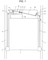
- Figure 1 a schematic configuration diagram showing an elevator device that is an example according to the present invention.
- the elevator device includes: a car 1; a position sensor 3; an electric actuator 10; a drive mechanism (12 to 20); a lifting rod 21; and a safety gear 2.
- the car 1 is hung on a main rope (not shown) in a hoistway provided in a building and is slidably engaged with a guide rail 4 by a guide device.
- a driving device traction machine, not shown
- the car 1 is moved up and down in the hoistway.
- the position sensor 3 which is mounted to the car 1, detects the position of the car 1 in the hoistway and always detects an elevating speed of the car 1 based on the detected position of the car 1. That is, the overspeed state of the car going over a predetermined speed limit can be detected by the position sensor 3.
- the position sensor 3 includes an image sensor. Based on image information acquired by the image sensor on a surface condition of a guide rail 4, the position sensor detects the position and the speed of the car 1. For example, the position of the car 1 is detected by checking image information acquired by the image sensor against image information which is previously measured on the surface condition of the guide rail 4 and stored in a memory device.
- a rotary encoder which is mounted to the car and rotates with the movement of the car is also usable as the position sensor.
- the electric actuator 10 is an electromagnetic actuator and is mounted to an upper part of the car 1.
- the electromagnetic actuator includes a movable piece or a movable bar which is actuated by a solenoid or electromagnet.
- the electric actuator 10 operates when the position sensor 3 detects a predetermined overspeed state of the car 1. At this time, the lifting rod 21 is lifted by the drive mechanism (12 to 20) connected to an operation lever 11. This brings the safety gear 2 into a brake state.
- the safety gear 2 is disposed on each side of the car 1, respectively.
- a pair of brake shoes (not shown) mounted to each of the safety gears 2 is movable between a brake position and a non-brake position. At the brake position, the brake shoes clamp the guide rail 4 therebetween.
- the brake shoes are relatively moved up with a downward movement of the car 1, a breaking force is generated by a frictional force applied between the brake shoes and the guide rail 4.
- the safety gear 2 is actuated when the car 1 falls into the overspeed state, and brings the car 1 into an emergency stop.
- the elevator device according to Example 1 hereof has a so-called ropeless governor system which does not use the governor rope.
- a rated speed for example, a speed less than 1.3 times the rated speed
- power supply to the driving device (traction machine) and power supply to a controller for controlling this driving device are shut off.
- a second overspeed for example, a speed less than 1.4 times the rated speed
- the electric actuator 10 mounted to the car 1 is electrically driven to actuate the safety gear 2 so that the car 1 is brought into the emergency stop.
- the ropeless governor system includes the above-described position sensor 3, and a safety controller for determining the overspeed state of the car 1 based on an output signal from the position sensor 3.
- This safety controller measures a speed of the car 1 based on an output signal from the position sensor 3.
- the safety controller Upon determining that the measured speed has reached the first overspeed, the safety controller outputs command signals to shut off the power to the driving device (traction machine) and the power to the controller for controlling the driving device.
- the safety controller Upon determining that the measured speed reaches the second overspeed, the safety controller outputs a command signal to actuate the electric actuator 10.
- the pair of brake shoes of the safety gear 2 When the pair of brake shoes of the safety gear 2 is lifted by the lifting rod 21, the pair of brake shoes clamps the guide rail 4 therebetween.
- the lifting rod 21 is driven by the drive mechanism (12 to 20) connected to the electric actuator 10.
- the operation lever 11 and a first operation piece 16 of the electric actuator 10 are interconnected to form a first link member substantially shaped like "T".
- the operation lever 11 and the first operation piece 16 constitute a head portion and a leg portion of the "T" shape, respectively.
- the substantially "T" shaped first link member is rotatably supported by a crosshead 50 via a first operation shaft 19.
- An end of one (on the left side as seen in the figure) of the paired lifting rods 21 is connected to an end of the first operation piece 16 on the opposite side from the interconnection between the operation lever 11 and the first operation piece 16 constituting the "T" shape.
- connection piece 17 and a second operation piece 18 are interconnected to constitute a second link member substantially shaped like "T".
- the connection piece 17 and the second operation piece 18 constitute a head portion and a leg portion of the "T" shape, respectively.
- the substantially “T” shaped second link member is rotatably supported by the crosshead 50 via a second operation shaft 20.
- An end of the other one (on the left side as seen in the figure) of the paired lifting rods 21 is connected to an end of the second operation piece 18 on the opposite side from the interconnection between the connection piece 17 and the second operation piece 18 constituting the leg portion of the "T" shape.
- An end of the operation lever 11 extended outward from the inside of a housing 30, and the one of the opposite ends of the connection piece 17 that is closer to the upper part of the car 1 than the second operation shaft 20 are connected to one end (on the left side as seen in the figure) and the other end (on the right side as seen in the figure) of a drive shaft 12 extended above the car 1, respectively.
- the drive shaft 12 slidably extends through a fixation part 14 fixed to a crosshead 50.
- the drive shaft 12 passes through a pressure member 15, which is fixed to the drive shaft 12.
- the pressure member 15 is located proximal to the second link member (the connection piece 17, the second operation piece 18) of the fixation part 14.
- a drive spring 13 as an elastic body is disposed between the fixation part 14 and the pressure member 15.
- the drive shaft 12 is inserted through the drive spring 13.
- a housing cover 31 defining a top side of the housing 30 is provided with a flexible cover member 32 at an insertion part for the operation lever 11, as will be described hereinafter. This is effective to prevent the invasion of dusts and foreign substances into the housing 30 where the mechanism part of the electric actuator 10 is contained.
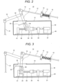
- Figure 2 shows the mechanism part of the electric actuator 10 which is contained in the housing 30 of the electric actuator 10 according to the example.
- Figure 2 is a front view showing the mechanism part in installation state shown in Figure 1 .
- the safety gear is in a non-operating state while the electric actuator 10 is in a standby state. That is, the elevator device is in normal operation.
- an armature 34 connected to the operation lever 11 is magnetically attracted by an excited electromagnet 35.
- the operation lever 11 is restricted from moving against a biasing of a drive spring 13 (compression spring).
- the operation lever 11 is connected to the armature 34 via a bracket 38 rotatably mounted to the armature 34.
- at least a portion electromagnetically stuck on the electromagnet 35 is made of a magnetic material.
- the flexible cover member 32 for covering an opening through which the operation lever 11 passes in the housing cover 31 defining the top side of the housing 30 is formed at this opening.
- the cover member 32 is formed of a thin plate of rubber member, for example. Since the cover member 32 is flexible, the motion of the operation lever 11 for actuating the safety gear is not interfered.
- the cover member 32 prevents dusts and foreign substances from invading into the housing 30 and from adhering to or contacting with the mechanism parts. Therefore, the electric actuator is improved in the operational reliability in the installation environment (in the hoistway and the like). Thus, the safety gear is improved in the operational reliability.
- the operation lever 11 is further provided with a plate-shaped member 33.
- the plate-shaped member 33 is fixed to a connection portion between the bracket 38 and the operation lever 11.
- a flat portion of the plate-shaped member 33 is located just below the opening through which the operation lever 11 passes and in its surrounding space and covers the mechanism parts located just below the opening.
- Figure 3 shows the functional part contained in the housing 30 of the electric actuator 10 according to the example hereof. Namely, Figure 3 is a front view of the functional part in the installed state as shown in Figure 1 . It is noted that the safety gear in Figure 2 is in the brake state while the electric actuator 10 is in an operating state. That is, the elevator device is stopped by the safety gear.
- the electric actuator 10 includes a feed screw 36 located above a plane part of a substrate 40 in order to drive the armature 34.
- the feed screw is rotatably supported by a first support member 41 and a second support member 42 which are fixed to the plane part of the substrate 40.
- the electromagnet 35 includes a nut portion which is threadably engaged with the feed screw 36.
- the feed screw 36 is rotated by a motor 37.
- the electric actuator 10 is returned to the standby state as follows.
- the feed screw is rotated by driving the motor 37 while exciting the electromagnet 35.
- the rotation of the motor is converted to a linear movement of the electromagnet 35 along an axial direction of the feed screw.
- the electromagnet 35 draws toward the moved position of the armature 34 shown in Figure 3 so that the armature 34 is acted to the electromagnetic force of the electromagnet 35, sticking fast to the electromagnet 35.
- the feed screw is reversed by reversely rotating the motor 37 while keeping the electromagnet 35 excited.
- the armature 34 is moved to the standby position along with the electromagnet 35.
- the plate-shaped member 33 is fixed to the operation lever 11 within the space of the housing 30. Hence, the plate-shaped member 33 moves along with the operation lever 11. Namely, the plate-shaped member 33 does not interfere with the movement of the operation lever 11.
- the plate-shaped member 33 and the operation lever 11 are tightly fitted with each other or firmly attached to each other by means of an adhesive agent or a joining material in order to fix the plate-shaped member 33 to the operation lever 11. Therefore, the plate-shaped member 33 and the operation lever 11 are connected to each other with no space formed therebetween. Therefore, the plate-shaped member 33 reliably prevents dusts, foreign substances, and the like from adhering to or contacting the mechanism parts.
- Figure 4 is a top view of the electric actuator 10 showing a configuration and fixation position of the flexible cover member 32 according to the example. As seen in Figure 4 , the electric actuator is in the standby state.
- the cover member 32 is fixed to place in a manner to cover the opening B.
- the cover member 32 As placed over the opening B, the cover member 32 includes an aperture A at place corresponding to a position passed by the operation lever 11 in the standby state.
- the cover member 32 further includes a slit S extended in a direction where the operation lever 11 is moved.
- the slit S may only be in the form of a cut line, including no gap.
- the cover member 32 is made of a flexible material such as rubber, the cover member warps with the movement of the operation lever 11, not interfering with the movement of the operation lever 11. Furthermore, the cover member 32 includes the slit S according to the example. Hence, the operation lever 11 receives less resistive force from the cover member 32. This ensures the prevention of interference with the movement of the operation lever 11.
- Figure 5 is a top view of the electric actuator 10 showing a positional relation between the flexible cover member 32 and the plate-shaped member 33 fixed to the operation lever 11 according to the example hereof.
- the plate-shaped member 33 is indicated by a broken line.
- the electric actuator is in the standby state.
- the flat portion of the plate-shaped member 33 is located just below the opening B ( Figure 4 ). Furthermore, the flat portion of the plate-shaped member 33 extends from a region just below the opening B ( Figure 4 ) in a longitudinal direction of the cover member 32 or the opening B ( Figure 4 ) or in a direction perpendicular to the longitudinal direction of the feed screw. Therefore, the plate-shaped member 33 partially overlies the armature 34 connected with the operation lever 11 and the feed screw 36 adjoining the armature 34. This reliably prevents the adhesion or contact of dusts or foreign substances to or with these mechanism parts.
- a longitudinal direction of the slit S (see Figure 4 ) of the cover member 32 is aligned with the axial direction of the feed screw as shown in Figure 5 . Therefore, the cover member 32 does not interfere with not only the motion of the operation lever 11 being shifted from the standby state to the brake state but also the motion of the operation lever 11 being returned to the standby state.
- the adhesion or contact of dusts and foreign substances to or with the mechanism parts can be prevented.
- the electric actuator can be improved in the operational reliability in the installation environment. Accordingly, the operation of the safety gear and the emergency stop operation of the elevator device are increased in reliability.
- the present invention is not limited to the foregoing example but may include a variety of modifications.
- the foregoing example is a detailed description of the present invention for clarity, but the present invention is not necessarily limited to examples including all the components described.
- a part of the structure of the example permits addition of or replacement with another structure, or cancellation thereof.
- the electric actuator 10 may be mounted not only to the upper part of the car 1 but also to a lower part or a side part thereof. Furthermore, the electric actuator can have a linear actuator.
Landscapes
- Engineering & Computer Science (AREA)
- Mechanical Engineering (AREA)
- Maintenance And Inspection Apparatuses For Elevators (AREA)
- Cage And Drive Apparatuses For Elevators (AREA)
Abstract
Description
- The present invention relates to an elevator device equipped with a safety gear actuated by an electric actuator.
- The elevator device has a governor and the safety gear for the purposes of always monitoring an elevating speed of the car and bringing the car into emergency stop when the car falls into an overspeed state. In general, the car and the governor are combined together by means of a governor rope. When detecting the overspeed state of the car, the governor actuates the safety gear on the car by restraining the governor rope. Thus, the car is brought into an emergency stop.
- In such an elevator device, the governor rope as a long object is installed in a hoistway, making it difficult to achieve space saving and cost reduction. In a case where the governor rope swings, a machine structure and the governor rope in the hoistway easily interfere with each other.
- Conversely, a safety gear without the governor rope has been proposed.
- A prior art technique related to a safety gear free from the governor rope is disclosed in
Patent literature 1. According to the prior art, a braking unit including a wedge-shaped brake shoe is provided under the car. The brake shoe is connected to a braking linkage. When a solenoid is actuated in response to a command from a controller, the braking strut is moved up by means of a mechanism interlocked with the solenoid. Thus, the brake shoe is pulled up so that the car is braked. - Patent Literature 1:
Japanese Patent Application Laid-Open No. 2013-189283 - In the known safety gear, which is actuated by the actuator operated by the solenoid as described above, the safety gear may be decreased in operational reliability in a case where dusts adhere to a movable mechanism part of the actuator or where the movable mechanism part is damaged upon contact with some article, in an installation environment.
- Hence, the present invention provides an elevator device equipped with a safety gear adapted to enhance the operational reliability of the electric actuator in the installation environment.
- For solving the above problem, the elevator device according to the present invention includes: a car; a safety gear mounted to the car; and an electric actuator mounted to an upper part of the car and operative to actuate the safety gear, and has a configuration wherein the electric actuator includes: a housing; a mechanism part disposed in the housing; and an operation lever connected to the mechanism part and extended from the inside of the housing to the outside of the housing through an opening of the housing, the housing includes a cover member covering the opening, and the operation lever is inserted through the cover member.
- According to the present invention, the electric actuator can be improved in the operational reliability thereof in the installation environment.
- Other objects, features and advantageous effects will become apparent from the following description of example hereof.
-
-
Figure 1 is a schematic configuration diagram showing an elevator device according to an example. -
Figure 2 is a front view showing a mechanism part contained in a housing of an electric actuator according to the example hereof. -
Figure 3 is a front view showing the mechanism part contained in the housing of the electric actuator according to the example hereof. -
Figure 4 is a top view of the electric actuator showing a configuration and fixation position of a cover member according to the example hereof. -
Figure 5 is a top view of the electric actuator showing a positional relation between the cover member and a plate-shaped member according to the example hereof. - An elevator device as an embodiment according to the present invention will hereinbelow be described with an example referring to the accompanying drawings. In the drawings, the same or similar reference numerals are used to refer to the same structural elements or structural elements having the same or similar functions.
-
Figure 1 a schematic configuration diagram showing an elevator device that is an example according to the present invention. - As shown in
Figure 1 , the elevator device includes: acar 1; aposition sensor 3; anelectric actuator 10; a drive mechanism (12 to 20); alifting rod 21; and asafety gear 2. - The
car 1 is hung on a main rope (not shown) in a hoistway provided in a building and is slidably engaged with aguide rail 4 by a guide device. When the main rope is frictionally driven by a driving device (traction machine, not shown), thecar 1 is moved up and down in the hoistway. - The
position sensor 3, which is mounted to thecar 1, detects the position of thecar 1 in the hoistway and always detects an elevating speed of thecar 1 based on the detected position of thecar 1. That is, the overspeed state of the car going over a predetermined speed limit can be detected by theposition sensor 3. - According to the example, the
position sensor 3 includes an image sensor. Based on image information acquired by the image sensor on a surface condition of aguide rail 4, the position sensor detects the position and the speed of thecar 1. For example, the position of thecar 1 is detected by checking image information acquired by the image sensor against image information which is previously measured on the surface condition of theguide rail 4 and stored in a memory device. - It is noted that a rotary encoder which is mounted to the car and rotates with the movement of the car is also usable as the position sensor.
- According to the example, the
electric actuator 10 is an electromagnetic actuator and is mounted to an upper part of thecar 1. The electromagnetic actuator includes a movable piece or a movable bar which is actuated by a solenoid or electromagnet. Theelectric actuator 10 operates when theposition sensor 3 detects a predetermined overspeed state of thecar 1. At this time, thelifting rod 21 is lifted by the drive mechanism (12 to 20) connected to anoperation lever 11. This brings thesafety gear 2 into a brake state. - Incidentally, the drive mechanism (12 to 20) will be described hereinafter.
- The
safety gear 2 is disposed on each side of thecar 1, respectively. A pair of brake shoes (not shown) mounted to each of thesafety gears 2 is movable between a brake position and a non-brake position. At the brake position, the brake shoes clamp theguide rail 4 therebetween. When the brake shoes are relatively moved up with a downward movement of thecar 1, a breaking force is generated by a frictional force applied between the brake shoes and theguide rail 4. Thus, thesafety gear 2 is actuated when thecar 1 falls into the overspeed state, and brings thecar 1 into an emergency stop. - The elevator device according to Example 1 hereof has a so-called ropeless governor system which does not use the governor rope. When the elevating speed of the
car 1 exceeds a rated speed to reach a first overspeed (for example, a speed less than 1.3 times the rated speed), power supply to the driving device (traction machine) and power supply to a controller for controlling this driving device are shut off. When a descending speed of thecar 1 reaches a second overspeed (for example, a speed less than 1.4 times the rated speed), theelectric actuator 10 mounted to thecar 1 is electrically driven to actuate thesafety gear 2 so that thecar 1 is brought into the emergency stop. - According to the example hereof, the ropeless governor system includes the above-described
position sensor 3, and a safety controller for determining the overspeed state of thecar 1 based on an output signal from theposition sensor 3. This safety controller measures a speed of thecar 1 based on an output signal from theposition sensor 3. Upon determining that the measured speed has reached the first overspeed, the safety controller outputs command signals to shut off the power to the driving device (traction machine) and the power to the controller for controlling the driving device. Upon determining that the measured speed reaches the second overspeed, the safety controller outputs a command signal to actuate theelectric actuator 10. - When the pair of brake shoes of the
safety gear 2 is lifted by thelifting rod 21, the pair of brake shoes clamps theguide rail 4 therebetween. Thelifting rod 21 is driven by the drive mechanism (12 to 20) connected to theelectric actuator 10. - A configuration of the drive mechanism is described as below.
- The
operation lever 11 and afirst operation piece 16 of theelectric actuator 10 are interconnected to form a first link member substantially shaped like "T". Theoperation lever 11 and thefirst operation piece 16 constitute a head portion and a leg portion of the "T" shape, respectively. At an interconnection between theoperation lever 11 and thefirst operation piece 16, the substantially "T" shaped first link member is rotatably supported by acrosshead 50 via afirst operation shaft 19. An end of one (on the left side as seen in the figure) of the paired liftingrods 21 is connected to an end of thefirst operation piece 16 on the opposite side from the interconnection between theoperation lever 11 and thefirst operation piece 16 constituting the "T" shape. - A
connection piece 17 and asecond operation piece 18 are interconnected to constitute a second link member substantially shaped like "T". Theconnection piece 17 and thesecond operation piece 18 constitute a head portion and a leg portion of the "T" shape, respectively. At an interconnection between theconnection piece 17 and theoperation piece 18, the substantially "T" shaped second link member is rotatably supported by thecrosshead 50 via asecond operation shaft 20. An end of the other one (on the left side as seen in the figure) of the paired liftingrods 21 is connected to an end of thesecond operation piece 18 on the opposite side from the interconnection between theconnection piece 17 and thesecond operation piece 18 constituting the leg portion of the "T" shape. - An end of the
operation lever 11 extended outward from the inside of ahousing 30, and the one of the opposite ends of theconnection piece 17 that is closer to the upper part of thecar 1 than thesecond operation shaft 20 are connected to one end (on the left side as seen in the figure) and the other end (on the right side as seen in the figure) of adrive shaft 12 extended above thecar 1, respectively. Thedrive shaft 12 slidably extends through afixation part 14 fixed to acrosshead 50. Thedrive shaft 12 passes through apressure member 15, which is fixed to thedrive shaft 12. Thepressure member 15 is located proximal to the second link member (theconnection piece 17, the second operation piece 18) of thefixation part 14. Adrive spring 13 as an elastic body is disposed between thefixation part 14 and thepressure member 15. Thedrive shaft 12 is inserted through thedrive spring 13. - In the example, when the
electric actuator 10 is actuated, namely when the electromagnet is de-energized, an electromagnetic force restraining the movement of theoperation lever 11 against a biasing of thedrive spring 13 dissipates. Hence, thedrive shaft 12 is longitudinally driven by a biasing of thedrive spring 13 applied to thepressure member 15. Therefore, the first link member (theoperation lever 11, the first operation piece 16) rotates about thefirst operation shaft 19, while the second link member (theconnection piece 17, the second operation piece 18) rotates about thesecond operation shaft 20. As a result, the onelifting rod 21 connected to thefirst operation piece 16 of the first link member is driven and lifted. Further, the other liftingrod 21 connected to thesecond operation piece 18 of the second link member is driven and lifted. - According to the example, a
housing cover 31 defining a top side of thehousing 30 is provided with aflexible cover member 32 at an insertion part for theoperation lever 11, as will be described hereinafter. This is effective to prevent the invasion of dusts and foreign substances into thehousing 30 where the mechanism part of theelectric actuator 10 is contained. -
Figure 2 shows the mechanism part of theelectric actuator 10 which is contained in thehousing 30 of theelectric actuator 10 according to the example.Figure 2 is a front view showing the mechanism part in installation state shown inFigure 1 . As seen inFigure 2 , the safety gear is in a non-operating state while theelectric actuator 10 is in a standby state. That is, the elevator device is in normal operation. - In the standby state, as shown in
Figure 2 , anarmature 34 connected to theoperation lever 11 is magnetically attracted by anexcited electromagnet 35. Thus, theoperation lever 11 is restricted from moving against a biasing of a drive spring 13 (compression spring). It is noted that theoperation lever 11 is connected to thearmature 34 via abracket 38 rotatably mounted to thearmature 34. In thearmature 34, at least a portion electromagnetically stuck on theelectromagnet 35 is made of a magnetic material. - The other mechanism parts (36, 37, 40 to 42) shown in
Figure 2 will be described hereinafter (Figure 3 ). - According to the example, the
flexible cover member 32 for covering an opening through which theoperation lever 11 passes in thehousing cover 31 defining the top side of thehousing 30 is formed at this opening. The opening and is penetrated by theoperation lever 11. Thecover member 32 is formed of a thin plate of rubber member, for example. Since thecover member 32 is flexible, the motion of theoperation lever 11 for actuating the safety gear is not interfered. - The
cover member 32 prevents dusts and foreign substances from invading into thehousing 30 and from adhering to or contacting with the mechanism parts. Therefore, the electric actuator is improved in the operational reliability in the installation environment (in the hoistway and the like). Thus, the safety gear is improved in the operational reliability. - According to the example, the
operation lever 11 is further provided with a plate-shapedmember 33. The plate-shapedmember 33 is fixed to a connection portion between thebracket 38 and theoperation lever 11. In thehousing 30, a flat portion of the plate-shapedmember 33 is located just below the opening through which theoperation lever 11 passes and in its surrounding space and covers the mechanism parts located just below the opening. With this, even though dusts and foreign substances may invade into thehousing 30, dusts and foreign substances are prevented from adhering to or contacting the mechanism parts. Therefore, the electric actuator is more surely improved in the operational reliability in the installation environment (in the hoistway and the like). Thus, the safety gear is more surely improved in the operational reliability. -
Figure 3 shows the functional part contained in thehousing 30 of theelectric actuator 10 according to the example hereof. Namely,Figure 3 is a front view of the functional part in the installed state as shown inFigure 1 . It is noted that the safety gear inFigure 2 is in the brake state while theelectric actuator 10 is in an operating state. That is, the elevator device is stopped by the safety gear. - When the excitation of the
electromagnet 35 is stopped in response to a command from the unillustrated safety controller, an attracting force on thearmature 34 dissipates so that the biasing of thedrive spring 13 is released to drive thedrive shaft 12. When thedrive shaft 12 is driven, theoperation lever 11 connected to thedrive shaft 12 is rotated about thefirst operation shaft 19. Thus, thefirst operation piece 16 connected to theoperation lever 11 is rotated about thefirst operation shaft 19. Thus, the liftingrod 21 connected to the first operation piece is lifted. - When the
operation lever 11 rotates as described above, thearmature 34 connected to theoperation lever 11 is moved along the rotation direction of theoperation lever 11. As will be described as below, in order to return theelectric actuator 10 to the standby state as shown inFigure 2 , thearmature 34 is returned from the moved position (Figure 3 ) to a position at standby time (Figure 2 ) by means of the mechanism parts (36, 37, 40 to 42), the description of which is not described with reference toFigure 2 ). - As shown in
Figure 3 , theelectric actuator 10 includes afeed screw 36 located above a plane part of asubstrate 40 in order to drive thearmature 34. The feed screw is rotatably supported by afirst support member 41 and asecond support member 42 which are fixed to the plane part of thesubstrate 40. Theelectromagnet 35 includes a nut portion which is threadably engaged with thefeed screw 36. Thefeed screw 36 is rotated by amotor 37. - The
electric actuator 10 is returned to the standby state as follows. First, the feed screw is rotated by driving themotor 37 while exciting theelectromagnet 35. By the rotating feed screw and the nut portion of theelectromagnet 35, the rotation of the motor is converted to a linear movement of theelectromagnet 35 along an axial direction of the feed screw. Hence, theelectromagnet 35 draws toward the moved position of thearmature 34 shown inFigure 3 so that thearmature 34 is acted to the electromagnetic force of theelectromagnet 35, sticking fast to theelectromagnet 35. When thearmature 34 is stuck fast to theelectromagnet 35, the feed screw is reversed by reversely rotating themotor 37 while keeping theelectromagnet 35 excited. Thus, thearmature 34 is moved to the standby position along with theelectromagnet 35. - According to the example, the plate-shaped
member 33 is fixed to theoperation lever 11 within the space of thehousing 30. Hence, the plate-shapedmember 33 moves along with theoperation lever 11. Namely, the plate-shapedmember 33 does not interfere with the movement of theoperation lever 11. - According to the example, the plate-shaped
member 33 and theoperation lever 11 are tightly fitted with each other or firmly attached to each other by means of an adhesive agent or a joining material in order to fix the plate-shapedmember 33 to theoperation lever 11. Therefore, the plate-shapedmember 33 and theoperation lever 11 are connected to each other with no space formed therebetween. Therefore, the plate-shapedmember 33 reliably prevents dusts, foreign substances, and the like from adhering to or contacting the mechanism parts. -
Figure 4 is a top view of theelectric actuator 10 showing a configuration and fixation position of theflexible cover member 32 according to the example. As seen inFigure 4 , the electric actuator is in the standby state. - At an opening B of the
housing cover 31 defining the top side of thehousing 30, thecover member 32 is fixed to place in a manner to cover the opening B. - As placed over the opening B, the
cover member 32 includes an aperture A at place corresponding to a position passed by theoperation lever 11 in the standby state. Thecover member 32 further includes a slit S extended in a direction where theoperation lever 11 is moved. Incidentally, the slit S may only be in the form of a cut line, including no gap. - Since the
cover member 32 is made of a flexible material such as rubber, the cover member warps with the movement of theoperation lever 11, not interfering with the movement of theoperation lever 11. Furthermore, thecover member 32 includes the slit S according to the example. Hence, theoperation lever 11 receives less resistive force from thecover member 32. This ensures the prevention of interference with the movement of theoperation lever 11. -
Figure 5 is a top view of theelectric actuator 10 showing a positional relation between theflexible cover member 32 and the plate-shapedmember 33 fixed to theoperation lever 11 according to the example hereof. InFigure 5 , the plate-shapedmember 33 is indicated by a broken line. InFigure 5 , the electric actuator is in the standby state. - The flat portion of the plate-shaped
member 33 is located just below the opening B (Figure 4 ). Furthermore, the flat portion of the plate-shapedmember 33 extends from a region just below the opening B (Figure 4 ) in a longitudinal direction of thecover member 32 or the opening B (Figure 4 ) or in a direction perpendicular to the longitudinal direction of the feed screw. Therefore, the plate-shapedmember 33 partially overlies thearmature 34 connected with theoperation lever 11 and thefeed screw 36 adjoining thearmature 34. This reliably prevents the adhesion or contact of dusts or foreign substances to or with these mechanism parts. - As shown in
Figure 5 , a longitudinal direction of the slit S (seeFigure 4 ) of thecover member 32 is aligned with the axial direction of the feed screw as shown inFigure 5 . Therefore, thecover member 32 does not interfere with not only the motion of theoperation lever 11 being shifted from the standby state to the brake state but also the motion of theoperation lever 11 being returned to the standby state. - According to the example, as described above, the adhesion or contact of dusts and foreign substances to or with the mechanism parts can be prevented. Thus, the electric actuator can be improved in the operational reliability in the installation environment. Accordingly, the operation of the safety gear and the emergency stop operation of the elevator device are increased in reliability.
- It is to be understood that the present invention is not limited to the foregoing example but may include a variety of modifications. For instance, the foregoing example is a detailed description of the present invention for clarity, but the present invention is not necessarily limited to examples including all the components described. A part of the structure of the example permits addition of or replacement with another structure, or cancellation thereof.
- For example, the
electric actuator 10 may be mounted not only to the upper part of thecar 1 but also to a lower part or a side part thereof. Furthermore, the electric actuator can have a linear actuator. -
- 1:
- car
- 2:
- safety gear
- 3:
- position sensor
- 4:
- guide rail
- 10:
- electric actuator
- 11:
- operation lever
- 12:
- drive shaft
- 13:
- drive spring
- 14:
- fixation part
- 15:
- pressure member
- 16:
- operation piece
- 17:
- connection piece
- 18:
- operation piece
- 19:
- operation shaft
- 20:
- operation shaft
- 21:
- lifting rod
- 30:
- housing
- 31:
- housing cover
- 32:
- cover member
- 33:
- plate-shaped member
- 34:
- armature
- 35:
- electromagnet
- 36:
- feed screw
- 37:
- motor
- 38:
- bracket
- 40:
- substrate
- 41:
- support member
- 42:
- support member
- 50:
- crosshead
Claims (10)
- An elevator device comprising:a car;a safety gear device mounted to the car; andan electric actuator mounted to the car and operative to actuate the safety gear,wherein the electric actuator includes:a housing;a mechanism part disposed in the housing; andan operation lever connected to the mechanism part and extended from the inside of the housing to the outside of the housing through an opening of the housing,the housing includes a cover member for covering the opening, andthe operation lever is inserted through the cover member.
- The elevator device according to Claim 1,
wherein the cover member includes a slit extended in a moving direction of the operation lever. - The elevator device according to Claim 1,
wherein the electric actuator includes a plate-shaped member mounted to the operation lever as located in the housing. - The elevator device according to Claim 3,
wherein the plate-shaped member is located above the mechanism part. - The elevator device according to Claim 4,
wherein the plate-shaped member is located just below the cover member. - The elevator device according to Claim 5,
wherein a flat portion of the plate-shaped member covers an area just below the cover member and is larger than the cover member. - The elevator device according to Claim 1,
wherein the mechanism part of the electric actuator includes:an armature connected with the operation lever;an electromagnet attracting the armature when the electric actuator is in a standby state;a feed screw threadably engaged with a nut portion of the electromagnet; anda motor for driving the feed screw. - The elevator device according to Claim 7,
wherein the cover member is located directly above the feed screw. - The elevator device according to Claim 3,
wherein the mechanism part of the electric actuator includes:an armature connected with the operation lever;an electromagnet attracting the armature when the electric actuator is in the standby state;a feed screw threadably engaged with a nut portion of the electromagnet; anda motor for driving the feed screw, andthe plate-shaped member is disposed on the operation lever and at a connection part between the operation lever and the armature. - The elevator device according to Claim 9,
wherein a flat portion of the plate-shaped member covers the armature.
Applications Claiming Priority (1)
| Application Number | Priority Date | Filing Date | Title |
|---|---|---|---|
| PCT/JP2020/025494 WO2022003768A1 (en) | 2020-06-29 | 2020-06-29 | Elevator device |
Publications (2)
| Publication Number | Publication Date |
|---|---|
| EP4174009A1 true EP4174009A1 (en) | 2023-05-03 |
| EP4174009A4 EP4174009A4 (en) | 2024-04-03 |
Family
ID=79317604
Family Applications (1)
| Application Number | Title | Priority Date | Filing Date |
|---|---|---|---|
| EP20943249.1A Withdrawn EP4174009A4 (en) | 2020-06-29 | 2020-06-29 | ELEVATOR DEVICE |
Country Status (4)
| Country | Link |
|---|---|
| US (1) | US12122641B2 (en) |
| EP (1) | EP4174009A4 (en) |
| JP (1) | JP7407936B2 (en) |
| WO (1) | WO2022003768A1 (en) |
Families Citing this family (2)
| Publication number | Priority date | Publication date | Assignee | Title |
|---|---|---|---|---|
| CN115196462B (en) * | 2022-08-02 | 2024-01-19 | 苏州富士精工电梯有限公司 | Elevator car capable of limiting and limiting method thereof |
| EP4624404A1 (en) * | 2024-03-28 | 2025-10-01 | Wittur Holding GmbH | Safety gear assembly for an elevator |
Family Cites Families (14)
| Publication number | Priority date | Publication date | Assignee | Title |
|---|---|---|---|---|
| US2012729A (en) | 1934-09-29 | 1935-08-27 | Albert C Pisacano | Device for imparting rotating motion to toys |
| CA2544664C (en) * | 2004-05-25 | 2011-06-14 | Mitsubishi Denki Kabushiki Kaisha | Safety device for an elevator |
| JP2010089930A (en) * | 2008-10-09 | 2010-04-22 | Mitsubishi Electric Corp | Safety device of elevator |
| EP2408702B1 (en) * | 2009-03-16 | 2018-09-19 | Otis Elevator Company | Over-acceleration and over-speed detection and processing system |
| US9850094B2 (en) * | 2011-12-21 | 2017-12-26 | Inventio Ag | Actuator for an elevator brake |
| JP5481510B2 (en) | 2012-03-13 | 2014-04-23 | 株式会社東芝 | Stop device and elevator equipped with the same |
| JP6370012B1 (en) * | 2017-06-13 | 2018-08-08 | 東芝エレベータ株式会社 | Safety link release force setting method and apparatus |
| JP6751373B2 (en) * | 2017-06-27 | 2020-09-02 | 株式会社日立製作所 | Emergency stop device and elevator |
| JP2019077533A (en) * | 2017-10-24 | 2019-05-23 | 株式会社日立製作所 | Emergency stop device and elevator |
| JP7204448B2 (en) * | 2018-11-28 | 2023-01-16 | 株式会社日立製作所 | Emergency stop device and elevator |
| JP7292230B2 (en) * | 2020-02-20 | 2023-06-16 | 株式会社日立製作所 | Emergency stop device and elevator |
| CN115397760B (en) * | 2020-04-21 | 2023-04-28 | 株式会社日立制作所 | Emergency braking device and elevator |
| WO2022038656A1 (en) * | 2020-08-17 | 2022-02-24 | 株式会社日立製作所 | Elevator device |
| CN116419904B (en) * | 2020-12-07 | 2024-08-30 | 株式会社日立制作所 | Elevator device |
-
2020
- 2020-06-29 WO PCT/JP2020/025494 patent/WO2022003768A1/en not_active Ceased
- 2020-06-29 US US18/010,507 patent/US12122641B2/en active Active
- 2020-06-29 EP EP20943249.1A patent/EP4174009A4/en not_active Withdrawn
- 2020-06-29 JP JP2022533270A patent/JP7407936B2/en active Active
Also Published As
| Publication number | Publication date |
|---|---|
| JPWO2022003768A1 (en) | 2022-01-06 |
| EP4174009A4 (en) | 2024-04-03 |
| US20230257231A1 (en) | 2023-08-17 |
| JP7407936B2 (en) | 2024-01-04 |
| US12122641B2 (en) | 2024-10-22 |
| CN115702113A (en) | 2023-02-14 |
| WO2022003768A1 (en) | 2022-01-06 |
Similar Documents
| Publication | Publication Date | Title |
|---|---|---|
| US7575099B2 (en) | Remotely resettable ropeless emergency stopping device for an elevator | |
| US12122641B2 (en) | Elevator device | |
| JP7470651B2 (en) | Elevator Equipment | |
| CN101663223A (en) | Brake for elevator hoist | |
| JP7558754B2 (en) | Emergency stop devices and elevators | |
| EP4410727A1 (en) | Elevator device | |
| EP4328166B1 (en) | Elevator apparatus | |
| CN115702113B (en) | Elevator device | |
| US11866299B2 (en) | Elevator apparatus | |
| JP7216839B2 (en) | elevator equipment | |
| CN101258088A (en) | Extend the application of shaft backup | |
| CN115716622A (en) | Elevator device | |
| JP7588657B2 (en) | Elevator Equipment | |
| CN117794838B (en) | Elevator device | |
| WO2022013939A1 (en) | Elevator device | |
| JP7562006B2 (en) | Elevator Equipment | |
| WO2022172364A1 (en) | Elevator apparatus | |
| JP7556160B2 (en) | Elevator Equipment | |
| KR101220355B1 (en) | Electric parking brake | |
| WO2024121925A1 (en) | Terminal floor forced deceleration device for elevator | |
| WO2025210701A1 (en) | Method for inspecting elevator apparatus, and device for inspecting elevator apparatus | |
| WO2022201529A1 (en) | Elevator apparatus | |
| WO2022038665A1 (en) | Elevator device |
Legal Events
| Date | Code | Title | Description |
|---|---|---|---|
| STAA | Information on the status of an ep patent application or granted ep patent |
Free format text: STATUS: THE INTERNATIONAL PUBLICATION HAS BEEN MADE |
|
| PUAI | Public reference made under article 153(3) epc to a published international application that has entered the european phase |
Free format text: ORIGINAL CODE: 0009012 |
|
| STAA | Information on the status of an ep patent application or granted ep patent |
Free format text: STATUS: REQUEST FOR EXAMINATION WAS MADE |
|
| 17P | Request for examination filed |
Effective date: 20230130 |
|
| AK | Designated contracting states |
Kind code of ref document: A1 Designated state(s): AL AT BE BG CH CY CZ DE DK EE ES FI FR GB GR HR HU IE IS IT LI LT LU LV MC MK MT NL NO PL PT RO RS SE SI SK SM TR |
|
| DAV | Request for validation of the european patent (deleted) | ||
| DAX | Request for extension of the european patent (deleted) | ||
| REG | Reference to a national code |
Ref country code: DE Ref legal event code: R079 Free format text: PREVIOUS MAIN CLASS: B66B0005040000 Ipc: B66B0005180000 |
|
| A4 | Supplementary search report drawn up and despatched |
Effective date: 20240305 |
|
| RIC1 | Information provided on ipc code assigned before grant |
Ipc: B66B 5/18 20060101AFI20240228BHEP |
|
| GRAP | Despatch of communication of intention to grant a patent |
Free format text: ORIGINAL CODE: EPIDOSNIGR1 |
|
| STAA | Information on the status of an ep patent application or granted ep patent |
Free format text: STATUS: GRANT OF PATENT IS INTENDED |
|
| INTG | Intention to grant announced |
Effective date: 20241018 |
|
| STAA | Information on the status of an ep patent application or granted ep patent |
Free format text: STATUS: THE APPLICATION IS DEEMED TO BE WITHDRAWN |
|
| 18D | Application deemed to be withdrawn |
Effective date: 20250219 |