EP4173864A1 - Side trim and crash structure for an energy store of a motor vehicle - Google Patents
Side trim and crash structure for an energy store of a motor vehicle Download PDFInfo
- Publication number
- EP4173864A1 EP4173864A1 EP22201624.8A EP22201624A EP4173864A1 EP 4173864 A1 EP4173864 A1 EP 4173864A1 EP 22201624 A EP22201624 A EP 22201624A EP 4173864 A1 EP4173864 A1 EP 4173864A1
- Authority
- EP
- European Patent Office
- Prior art keywords
- crash structure
- profile
- side panel
- crash
- motor vehicle
- Prior art date
- Legal status (The legal status is an assumption and is not a legal conclusion. Google has not performed a legal analysis and makes no representation as to the accuracy of the status listed.)
- Granted
Links
- 230000007423 decrease Effects 0.000 claims description 7
- 239000002828 fuel tank Substances 0.000 claims description 4
- 230000021715 photosynthesis, light harvesting Effects 0.000 claims description 4
- 238000009434 installation Methods 0.000 description 7
- 238000004146 energy storage Methods 0.000 description 4
- 230000004308 accommodation Effects 0.000 description 2
- 238000002485 combustion reaction Methods 0.000 description 2
- 230000008878 coupling Effects 0.000 description 2
- 238000010168 coupling process Methods 0.000 description 2
- 238000005859 coupling reaction Methods 0.000 description 2
- 239000000446 fuel Substances 0.000 description 2
- 230000002787 reinforcement Effects 0.000 description 2
- -1 As diesel Substances 0.000 description 1
- 238000005452 bending Methods 0.000 description 1
- UQMRAFJOBWOFNS-UHFFFAOYSA-N butyl 2-(2,4-dichlorophenoxy)acetate Chemical compound CCCCOC(=O)COC1=CC=C(Cl)C=C1Cl UQMRAFJOBWOFNS-UHFFFAOYSA-N 0.000 description 1
- 238000010276 construction Methods 0.000 description 1
- 230000001419 dependent effect Effects 0.000 description 1
- 238000011161 development Methods 0.000 description 1
- 230000018109 developmental process Effects 0.000 description 1
- 238000005516 engineering process Methods 0.000 description 1
- 239000002737 fuel gas Substances 0.000 description 1
- 239000003502 gasoline Substances 0.000 description 1
- 239000001257 hydrogen Substances 0.000 description 1
- 229910052739 hydrogen Inorganic materials 0.000 description 1
- 125000004435 hydrogen atom Chemical class [H]* 0.000 description 1
- 238000007373 indentation Methods 0.000 description 1
- 239000002184 metal Substances 0.000 description 1
- 238000000034 method Methods 0.000 description 1
- 238000012986 modification Methods 0.000 description 1
- 230000004048 modification Effects 0.000 description 1
- 230000035515 penetration Effects 0.000 description 1
- 230000008569 process Effects 0.000 description 1
- 230000001681 protective effect Effects 0.000 description 1
- 230000007704 transition Effects 0.000 description 1
- 230000003313 weakening effect Effects 0.000 description 1
Images


Classifications
-
- B—PERFORMING OPERATIONS; TRANSPORTING
- B60—VEHICLES IN GENERAL
- B60K—ARRANGEMENT OR MOUNTING OF PROPULSION UNITS OR OF TRANSMISSIONS IN VEHICLES; ARRANGEMENT OR MOUNTING OF PLURAL DIVERSE PRIME-MOVERS IN VEHICLES; AUXILIARY DRIVES FOR VEHICLES; INSTRUMENTATION OR DASHBOARDS FOR VEHICLES; ARRANGEMENTS IN CONNECTION WITH COOLING, AIR INTAKE, GAS EXHAUST OR FUEL SUPPLY OF PROPULSION UNITS IN VEHICLES
- B60K1/00—Arrangement or mounting of electrical propulsion units
- B60K1/04—Arrangement or mounting of electrical propulsion units of the electric storage means for propulsion
-
- B—PERFORMING OPERATIONS; TRANSPORTING
- B60—VEHICLES IN GENERAL
- B60R—VEHICLES, VEHICLE FITTINGS, OR VEHICLE PARTS, NOT OTHERWISE PROVIDED FOR
- B60R3/00—Arrangements of steps or ladders facilitating access to or on the vehicle, e.g. running-boards
-
- B—PERFORMING OPERATIONS; TRANSPORTING
- B62—LAND VEHICLES FOR TRAVELLING OTHERWISE THAN ON RAILS
- B62D—MOTOR VEHICLES; TRAILERS
- B62D21/00—Understructures, i.e. chassis frame on which a vehicle body may be mounted
- B62D21/02—Understructures, i.e. chassis frame on which a vehicle body may be mounted comprising longitudinally or transversely arranged frame members
-
- B—PERFORMING OPERATIONS; TRANSPORTING
- B62—LAND VEHICLES FOR TRAVELLING OTHERWISE THAN ON RAILS
- B62D—MOTOR VEHICLES; TRAILERS
- B62D21/00—Understructures, i.e. chassis frame on which a vehicle body may be mounted
- B62D21/15—Understructures, i.e. chassis frame on which a vehicle body may be mounted having impact absorbing means, e.g. a frame designed to permanently or temporarily change shape or dimension upon impact with another body
- B62D21/157—Understructures, i.e. chassis frame on which a vehicle body may be mounted having impact absorbing means, e.g. a frame designed to permanently or temporarily change shape or dimension upon impact with another body for side impacts
-
- B—PERFORMING OPERATIONS; TRANSPORTING
- B60—VEHICLES IN GENERAL
- B60Y—INDEXING SCHEME RELATING TO ASPECTS CROSS-CUTTING VEHICLE TECHNOLOGY
- B60Y2200/00—Type of vehicle
- B60Y2200/10—Road Vehicles
- B60Y2200/14—Trucks; Load vehicles, Busses
-
- B—PERFORMING OPERATIONS; TRANSPORTING
- B60—VEHICLES IN GENERAL
- B60Y—INDEXING SCHEME RELATING TO ASPECTS CROSS-CUTTING VEHICLE TECHNOLOGY
- B60Y2200/00—Type of vehicle
- B60Y2200/10—Road Vehicles
- B60Y2200/14—Trucks; Load vehicles, Busses
- B60Y2200/141—Light trucks
-
- B—PERFORMING OPERATIONS; TRANSPORTING
- B60—VEHICLES IN GENERAL
- B60Y—INDEXING SCHEME RELATING TO ASPECTS CROSS-CUTTING VEHICLE TECHNOLOGY
- B60Y2200/00—Type of vehicle
- B60Y2200/10—Road Vehicles
- B60Y2200/14—Trucks; Load vehicles, Busses
- B60Y2200/142—Heavy duty trucks
-
- B—PERFORMING OPERATIONS; TRANSPORTING
- B60—VEHICLES IN GENERAL
- B60Y—INDEXING SCHEME RELATING TO ASPECTS CROSS-CUTTING VEHICLE TECHNOLOGY
- B60Y2306/00—Other features of vehicle sub-units
- B60Y2306/01—Reducing damages in case of crash, e.g. by improving battery protection
Definitions
- the invention relates to a device with an energy store, crash structure and side paneling for a motor vehicle, preferably a commercial vehicle.
- the DE 10 2020 116 312 A1 discloses, for example, a recreational vehicle in which a rear support member is provided.
- An energy storage unit is provided in a frame of the recreational vehicle and the rear support member is arranged behind the energy storage.
- An energy-absorbing crash element is arranged on the rear support element.
- DE 10 2018 121 227 A1 relates to a truck having an energy supply module.
- the energy supply module has a base frame.
- a crash structure is arranged on the longitudinal outer sides of the base frame.
- the crash structure is designed in such a way that, in the event of a side impact, it absorbs impact energy with a predetermined plastic deformation.
- the invention is based on the object of creating an arrangement with a crash structure for a motor vehicle in which the crash structure protects an energy store and requires as little additional space as possible, preferably with respect to a transverse axis of the motor vehicle.
- the device has an energy store, preferably a traction battery or a fuel tank.
- the device has a crash structure that protectively covers an outside of the energy store (eg essentially completely) and is preferably designed to deform in a predetermined manner in the event of a (eg side) impact with energy dissipation.
- the device has a (z. B. substantially plate-shaped) side panel that covers an outside of the crash structure facing away from the energy store.
- the side panel has an inside facing the outside of the crash structure and an outside oriented opposite to the inside of the side panel.
- the inside of the side panel is set back in sections towards the outside of the side panel to form a receiving space, preferably with an essentially concave or shell-like contour in (eg, transverse and/or longitudinal) section.
- the crash structure is at least partially arranged in the receiving space.
- the partial arrangement of the crash structure in the receiving space advantageously allows the combination of crash structure and side paneling to take up as little installation space as possible.
- the crash structure and the side paneling can virtually share installation space without impairing the respective function.
- this technology enables a comparatively large crash structure without requiring a particularly large amount of installation space.
- the crash structure can simply dip into the receiving space. This can also make it possible, for example, to dimension the energy store as large as possible while complying with any legal provisions on the maximum width of the motor vehicle, in order to enable the motor vehicle to have the greatest possible range.
- Particularly preferred variants are described below, which can make particularly effective use of the advantages mentioned.
- the crash structure is preferably designed to deform in a predetermined manner in such a way that the crash structure is not penetrated, makes penetration more difficult and/or is supported over a large area on a structure (e.g. housing of the energy store) arranged behind the crash structure.
- the predetermined deformation can be such that the crash structure deforms within its installation space and crash energy is reduced in the process.
- the predetermined deformation can include an indentation, a bulging and/or a bending of a profile and/or a profile track of the crash structure.
- the outside of the crash structure has a profile that is at least partially arranged in the receiving space and/or dips into or protrudes into the receiving space.
- an upper section and/or a lower section of the side paneling has a profiling (eg for stiffening the side paneling), which is opposite a section of the profiling of the crash structure.
- the section of the profiling of the crash structure is flattened compared to the rest of the profiling of the crash structure.
- the profiling in the upper and lower area of the crash structure can thus rise less, so that it offers more space for the structure of the full side paneling in the areas subjected to less energy in a typical impact. It is even possible that in this way the side paneling can also be installed in motor vehicles without a crash structure as part of a common parts strategy, since the side paneling itself is sufficiently stiff and can be easily connected in the upper and lower section.
- the accommodation space extends essentially along the entire length of the side panel and/or the crash structure.
- the receiving space extends over at least 40%, 50%, 60%, 70% or 80% of the total height of the side panel.
- the crash structure is designed as a crash skin.
- the crash structure is designed as a rolled profile, an extruded profile or a pressed part.
- the crash structure is attached to a housing of the energy store, preferably screwed.
- the crash structure is preferably supported at least in sections over a large area on the energy store, preferably with profile valleys of a profile and/or a plurality of profile tracks of the crash structure.
- an effective width of the crash structure is greatest in a substantially central (e.g. strip-shaped) section of the crash structure and preferably falls upwards and/or downwards (whereby, for example, the effective width in relation to a transverse axis of the crash structure is measured perpendicular to an alignment plane of the crash structure).
- the crash structure is reinforced and/or widened in a substantially central section of the crash structure compared to an upper section of the crash structure and/or a lower section of the crash structure (e.g. measured with respect to a transverse axis of the crash structure perpendicular to an alignment plane of the crash structure).
- the profiling can thus rise less, preferably in the upper and lower area of the crash structure, so that it offers more space for the structure of the full side paneling in the areas subjected to less energy in a typical impact.
- the crash structure (or the profiling of the crash structure) has a plurality of profile tracks.
- the multiple profile tracks run parallel to one another.
- the several profiled tracks have a U-shaped, V-shaped and/or wavy cross-section.
- the multiple profile tracks are parallel, oblique or perpendicular to a longitudinal axis of the crash structure.
- the multiple profile tracks are at least partially different in width or height (eg measured with respect to a transverse axis of the crash structure perpendicular to an alignment plane of the crash structure).
- an upper profile track of the multiple profile tracks is less wide or taller than a middle profile track of the multiple profile tracks (e.g. measured with respect to a transverse axis of the crash structure perpendicular to an alignment plane of the crash structure).
- a roof surface of an upper profile sheet of the plurality of profile sheets facing the side panel slopes downwards, so that a width or height of the upper profile sheet (measured e.g. with respect to a transverse axis of the crash structure perpendicular to an alignment plane of the crash structure) is upwards along a vertical direction decreases.
- a lower profile track of the multiple profile tracks is less wide or high than a middle profile track of the multiple profile tracks (e.g. measured with respect to a transverse axis of the crash structure perpendicular to an alignment plane of the crash structure).
- a roof surface of a lower profile sheet of the plurality of profile sheets facing the side panel slopes downwards, so that a width or height (measured e.g. with respect to a transverse axis of the crash structure perpendicular to an alignment plane of the crash structure) of the lower profile sheet is downward along a vertical direction decreases.
- a middle profile sheet of the plurality of profile sheets is the widest or tallest of the plurality of profile sheets (eg, measured with respect to a transverse axis of the crash structure perpendicular to an alignment plane of the crash structure).
- the side panel is reinforced and/or widened in an upper section of the side panel and/or in a lower section of the side panel compared to a central section of the side panel (e.g. measured with respect to a transverse axis of the crash structure perpendicular to an alignment plane of the crash structure ).
- the side panel is multi-shell, and an inner shell of the side panel is reinforced and/or widened in an upper section of the inner shell and/or in a lower section of the inner shell compared to a central section of the inner shell (e.g. measured with respect to a transverse axis of the crash structure perpendicular to an alignment plane of the crash structure).
- the upper section of the side panel and/or the inner shell can be arranged directly opposite the upper profile sheet.
- the central section of the side panel and/or the inner shell can be arranged directly opposite the central profile sheet.
- the lower section of the side panel and/or the inner shell can preferably be arranged directly opposite the lower profile sheet.
- the side paneling encompasses the crash structure from below and/or the side paneling is mounted so that it can be folded down.
- the device also has a preferably movable and/or foldable step for boarding the motor vehicle, the step being arranged in a recess in the side panel and/or in a recess in the crash structure. In this way, a particularly space-efficient arrangement of the step can be advantageously created.
- a profiling of the side paneling can preferably be more pronounced or broadened where directly opposite the profiling of the crash structure is less pronounced or flattened, and vice versa.
- a motor vehicle preferably a utility vehicle (e.g. truck or bus), is disclosed.
- the motor vehicle has a front axle, a rear axle and a vehicle frame, preferably a ladder frame.
- the motor vehicle further comprises a device as disclosed herein, the device being arranged between the front axle and the rear axle and/or fixed to the vehicle frame, preferably level with the front axle and the rear axle.
- the figure 1 shows a motor vehicle 10.
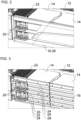
- the Figures 2, 3 , 4 and 6 show views of a portion of the motor vehicle 10, wherein in FIG figure 3 a side panel is not shown.
- the figure 5 only shows the side panels.
- the motor vehicle 10 is preferably embodied as a truck, as illustrated.
- the truck can, for example, have a structure, e.g. B. Loading structure (not in figure 1 shown).
- the truck can, for example, have a fifth wheel coupling for coupling a semi-trailer (not in figure 1 shown).
- the motor vehicle 10 can be in the form of a bus, a construction machine or an agricultural machine, for example. It is also possible that motor vehicle 10 is not designed as a commercial vehicle, but as a passenger car, for example.
- the motor vehicle 10 can have a vehicle frame 12 .
- the body or trailer may be supported on the vehicle frame 12 .
- the vehicle frame 12 may preferably be embodied as a ladder frame if the motor vehicle 10 is embodied as a truck, for example.
- the ladder frame can have, for example, two essentially parallel main longitudinal members.
- the two main longitudinal members can be connected to one another by a plurality of cross members.
- the plurality of cross members may be spaced apart from one another along a longitudinal axis of the motor vehicle 10 .
- the vehicle frame 12 can be designed, for example, as a lattice frame, e.g. B. in an embodiment of the motor vehicle 10 as a truck or a bus.
- Motor vehicle 10 can preferably be driven electrically.
- the motor vehicle 10 can be driven by means of a central electric drive.
- the central electric drive can be arranged, for example, below the driver's cab and/or between the two main longitudinal members of the vehicle frame 12 .
- the motor vehicle 10 can be driven, for example, by means of a number of electric wheel hub drives or a number of electric drives close to the wheel.
- Motor vehicle 10 has an energy store 14 , a crash structure 16 and side paneling 18 .
- the motor vehicle 10 can have at least one step 20 and/or a work platform 22 .
- the energy store 14 can be used, for example, as a fuel tank (e.g. pressure tank) for storing fuel, e.g. As diesel, gasoline, hydrogen, fuel gas, etc., be executed.
- the fuel tank can be connected to a drive unit of the motor vehicle 10 for supplying the fuel.
- the energy store 14 is preferably designed as a traction battery for storing electrical energy.
- the traction battery can be charged externally, for example, via an electrical charging cable connected to a charging socket of motor vehicle 10 .
- the traction battery can supply electrical energy to at least one electric drive of motor vehicle 10 .
- the energy store 14 can be arranged in a concealed manner behind the crash structure 16 and/or the side paneling 18 .
- the energy store 14 can be protected by the crash structure 16, e.g. B. in a side impact on the crash structure 16 and / or the side panel 18.
- the energy store 14 (z. B. with respect to a transverse axis of the motor vehicle 10) between the vehicle frame 12 and the crash structure 16 can be arranged.
- the energy store 14 can be arranged between a front axle and a rear axle of the motor vehicle 10 .
- Energy store 14 may be attached to vehicle frame 12, preferably to an outer longitudinal side of one of the main longitudinal members of vehicle frame 12.
- Side paneling 18 and/or crash structure 16 may be carried or attached to energy store 14, preferably to a (e.g. Longitudinal) side surface of the energy store 14, which is directed away from the vehicle frame 12 or to the outside.
- the crash structure 16 can be attached to a housing of the energy storage device 14, e.g. B. by screwing.
- the crash structure 16 is designed to deform in a predetermined manner under energy dissipation in the event of an impact in order to dissipate crash energy.
- the crash structure 16 can be designed to deform plastically in a predetermined manner with energy dissipation in the event of a side impact on the crash structure 16 and/or the side paneling 18 .
- the crash structure 16 can be arranged between a front axle and a rear axle of the motor vehicle 10 .
- the crash structure 16 can cover a section of a longitudinal side (eg driver's longitudinal side or passenger's longitudinal side) of the motor vehicle 10 in a protective manner against impact energy.
- the crash structure 16 can be arranged behind a fender for the front axle and/or in front of a fender for the rear axle with respect to a forward travel direction of the motor vehicle 10 .
- the crash structure 16 protects the energy store 14.
- the crash structure 16 can be arranged on an outer longitudinal side of the energy store 14.
- the crash structure 16 can essentially completely cover or protect an outer longitudinal side of the energy store 14 .
- Crash structure 16 can preferably extend essentially over an entire height and/or length (relative to a longitudinal axis of motor vehicle 10) of energy store 14.
- the crash structure 16 is arranged between the energy store 14 and the side panel 18 .
- the crash structure 16 can extend essentially parallel to a longitudinal axis of the motor vehicle 10 .
- the crash structure 16 is preferably arranged at the level of a front axle, a rear axle and/or the vehicle frame 12 of the motor vehicle 10 .
- the crash structure 16 is advantageously aligned vertically.
- the crash structure 16 is particularly preferably located in a vertical alignment plane which runs, for example, parallel to the longitudinal axis of the motor vehicle 10 and/or is arranged perpendicularly to the transverse axis Q of the crash structure 16 .
- the crash structure 16 is preferably essentially plate-shaped.
- the crash structure 16 can be designed as a crash skin.
- the crash structure 16 can preferably be designed as a rolled profile, an extruded profile or a pressed part.
- the crash structure 16 is preferably profiled.
- the crash structure 16 can have a plurality of profile tracks 24, 26, 28, 30, 32, 34.
- the profile tracks 24, 26, 28, 30, 32, 34 are preferably parallel to one another.
- the profile webs 24, 26, 28, 30, 32, 34 can preferably be arranged one above the other.
- the profile sheets 24, 26, 28, 30, 32, 34 can, for example, have a U-shaped, V-shaped or wavy cross-section transverse to their direction of longitudinal extent.
- the profile tracks 24, 26, 28, 30, 32, 34 can, for example, run parallel to a longitudinal axis of the motor vehicle 10 or the crash structure 16.
- the profile tracks 24, 26, 28, 30, 32, 34 can run, for example, parallel to a vertical axis of the motor vehicle 10 or the crash structure 16 or at an angle to the longitudinal axis and the vertical axis (ie, for example, diagonally). It is possible that the crash structure 16 has more or less than the six profile sheets 24, 26, 28, 30, 32, 34, e.g. B. two, three, four, five, seven, eight, etc. profile sheets.
- the profile tracks 24, 26, 28, 30, 32, 34 can at least partially have different widths, with a width of the profile tracks with respect to a transverse axis Q (see figure 6 ) of the crash structure 16 is measured.
- the transverse axis Q is perpendicular to the plane of orientation of the crash structure 16.
- the top panel 24 may be less wide than the top panel 26.
- the top panel 26 may be less wide than the middle panel 28.
- the middle panel 28 may be, for example, about as wide as the middle profile track 30.
- the middle profile track 30 can be wider than the lower profile track 32.
- the lower profile track 32 can be wider than the bottom profile track 34.
- the crash structure 16 in a central portion of the crash structure 16 against an upper portion of the crash structure 16 and / or a lower portion of the Crash structure 16 reinforced and / or widened.
- the upper portion may include the upper profile sheet 24 and/or 26.
- the middle section can have the middle profile sheet 28 and/or 30 .
- the lower section can have the lower profile sheet 32 and/or 34 .
- the middle section may be located between the top section and the bottom section.
- an effective width and/or profiling of the crash structure 16 can decrease downwards and/or upwards in a vertical direction, starting from a central section of the crash structure 16 .
- An effective width and/or profile of the crash structure 16 can be greatest in a central section.
- the effective width can relate to the respective maximum width of the profile sheet(s) in the respective section of the crash structure 16.
- the middle profile tracks 28, 30 are more heavily profiled than the above profile tracks 24, 26 and/or the lower profile tracks 32, 34.
- the roof surfaces of the profile sheets 24, 26, 28, 30, 32, 34 can face the side panel 18.
- the roof surface of the upper profile sheet 24 and/or 26 can slope downwards, so that the width of the upper profile sheet 24 and/or 26 decreases upwards in a vertical direction.
- the roof surface of the central profile sheet 28 and/or 30 can have an essentially constant width and can preferably be aligned vertically.
- the roof surface of the lower profile sheet 32 and/or 34 can slope downwards, so that the width of the lower profile sheet 32 and/or 34 decreases downwards in a vertical direction.
- the side panel 18 covers an outside of the crash structure 16 and thus preferably also an outside of the energy store 14.
- the side panel 18 can be arranged between a front axle and a rear axle of the motor vehicle 10.
- the side trim 18 may cover a portion of a longitudinal side (e.g., driver's longitudinal side or passenger's longitudinal side) of the motor vehicle 10 .
- the quarter panel 18 covers substantially an entire portion of the longitudinal side of the motor vehicle 10 between the front axle and the rear axle.
- the side panel 18 is designed as a full side panel.
- the side panel 18 can be arranged behind a fender for the front axle and/or in front of a fender for the rear axle with respect to a forward direction of travel of the motor vehicle 10 .
- the side panel 18 can extend essentially parallel to a longitudinal axis of the motor vehicle 10 .
- the side paneling 18 is preferably arranged at the level of a front axle, a rear axle, the crash structure 16, the energy store 14 and/or the vehicle frame 12.
- the side panel 18 is preferably plate-shaped.
- the side panel 18 is advantageously aligned vertically.
- Side paneling 18 can preferably encompass crash structure 16 from below. It is possible that the side panel 18 can be folded or pivoted downwards, e.g. B. to enable access to the crash structure 16 and/or the energy store 14 .
- a shape of an inside of the side panel 18 facing the crash structure 16 and a shape of an outside of the crash structure 16 facing the side panel 18 can be adapted to one another.
- the inside of the side panel 18 is set back or recessed in sections to form a receiving space 40 towards the outside of the side panel 18 (see in particular Figures 5 and 6 ).
- the inside of the side panel 18 can preferably have an essentially concave or shell-like contour in section.
- the crash structure 16 is at least partially arranged within the receiving space 40 .
- the accommodation space 40 can essentially extend along an entire length of the side panel 18 and/or the crash structure 16 .
- the receiving space 40 can be arranged approximately centrally with respect to a vertical axis of the side panel 18 .
- the receiving space 40 can extend over at least 40%, 50%, 60%, 70% or 80% of an overall height of the side panel 18 .
- the outside of the crash structure 16 preferably has a profile with the profile tracks 24, 26, 28, 30, 32, 34.
- This profiling can be arranged at least partially in the receiving space 40 and/or dip into the receiving space 40 .
- the side panel 18 can be supported on at least one of the profile sheets 24, 26, 28, 30, 32, 34, e.g. B. on a roof surface or a valley surface of the respective profile sheet 24, 26, 28, 30, 32, 34.
- An upper section and a lower section of the side panel 18 can also have a profile for stiffening the side panel 18 . These sections can be directly opposite a respective section of the profile of the crash structure 16 .
- the respective section of the profile of the crash structure 16 can preferably be flattened, in order to create space for the profiling of the side panel 18 in the upper and/or lower section of the side panel 18 .
- the profiling of the side panel 18 can be more pronounced or broadened where the profiling of the crash structure 16 is less pronounced or flattened directly opposite, and vice versa.
- the side panel 18 can be reinforced and/or widened relative to a central section of the side panel 18, measured with respect to the transverse axis Q.
- the upper section can be arranged at the level of the upper profile sheet 24.
- a profile of the upper section can follow a profile of the upper profile sheet 24 at least in sections.
- the side panel 18 can be reinforced and/or widened relative to a central section of the side panel 18, measured with respect to the transverse axis Q.
- the lower section can be arranged at the level of the lower profile sheet 34.
- a profile of the lower section can follow a profile of the lower profile sheet 34 at least in sections.
- the side panel 18 can have multiple shells, preferably two shells.
- the side panel 18 may include an outer shell 36 that faces outward.
- the side panel 18 may include an inner shell 38 facing the crash structure 16 .
- the inner shell 38 can increase rigidity of the side panel 18 .
- the inner shell 38 can be reinforced and/or widened in an upper portion of the inner shell 38 and/or in a lower portion of the inner shell 38, preferably compared to a central portion of the inner shell 38.
- the reinforcement and/or widening can increase the rigidity of the Raise side panel 18.
- a shape of the outside of the crash structure 16 can be adapted to a shape of the inner shell 38 (eg profile tracks of different heights, sloping roof surfaces, etc.).
- the motor vehicle 10 can be climbed on by means of the step 20 .
- the step 20 can be arranged in the crash structure 16 and the side panel 18 .
- the step 20 can be movable between a use position and a non-use position.
- FIG. 1 shows the step 20 schematically in the non-use position.
- the Figures 2 to 4 show the step 20 in the position of use.
- the step 20 can be walked on. In the usage position, the step 20 can be used to climb onto the motor vehicle 10 .
- the step 20 can be oriented essentially horizontally in the position of use.
- the step 20 can preferably not be walked on. In the non-use position, the step 20 cannot be used to climb onto the motor vehicle 10 when used as intended.
- the step 20 can be oriented essentially vertically in the non-use position.
- the step 20 can be pivoted or folded and/or shifted between the position of use and the position of non-use.
- the step 20 can preferably be folded out from the position of non-use into the position of use, preferably downwards.
- the step 20 can preferably be folded out of the position of use into the position of non-use, preferably upwards.
- a pivot axis of the step 20 can be essentially parallel to a longitudinal axis of the motor vehicle 10 .
- the step 20 can preferably be a sheet metal component.
- the step 20 preferably has a profiled stepping surface, for example to prevent slipping off the stepping surface.
- the step 20 can be arranged in at least one recess in the side paneling 18 and/or at least one recess in the crash structure 16 .
- the recesses can each be designed, for example, as a cutout and/or an opening, preferably a through-opening.
- the recesses are preferably rectangular.
- the recess in the crash structure 16 and/or the side panel 18 can frame the step 20 in the non-use position.
- the step 20 can preferably fill the recess in the crash structure 16 .
- the step 20 can lie in one plane with the recess in the crash structure 16 .
- the plane is preferably a vertical plane, particularly preferably a vertical longitudinal plane of motor vehicle 10.
- Step 20 can reduce or even overcompensate for a weakening of crash structure 16 in the area of the recess in crash structure 16.
- the step 20 can reinforce and/or stiffen the crash structure 16 in the area of the recess in the crash structure 16 .
- the reinforcement and/or stiffening can be in the non-use position and optionally also in the use position the step 20 be effected.
- the step 20 can assume the function of an (additional) crash structure within the crash structure 16 or in the recess of the crash structure 16 .
- the step 20 may be movable through the recess in the side panel 18 .
- the step 20 may be recessed relative to the side panel 18 or may be substantially flush with the side panel 18 .
- the step 20 can protrude beyond the side panel 18 or protrude from the recess in the side panel 18 .
- the work platform 22 can be reached by means of the step 20 .
- the step 20 can be moved into the position of use.
- the work platform 22 can be arranged behind a driver's cab of the motor vehicle 10 with respect to a forward direction of travel of the motor vehicle 10, preferably adjacent to a rear wall of the driver's cab.
- the work platform 22 can be arranged above the vehicle frame 12, expediently directly above the vehicle frame 12.
- the work platform 22 can be supported on the vehicle frame 12.
- the work platform 22 can be arranged between a front axle and a rear axle of the motor vehicle 10 .
- the working platform 22 can be arranged, preferably directly, above the step 20, the crash structure 16, the energy store 14 and/or the side paneling 18.
- connections of the motor vehicle 10 on the rear of the driver's cab and/or front connections of a trailer or semi-trailer of the motor vehicle 10 can be accessible, for example.
- the work platform 22 can have a rectangular shape, for example.
- the work platform 22 is preferably aligned horizontally.
- the invention is not limited to the preferred embodiments described above. Rather, a large number of variants and modifications are possible, which also make use of the idea of the invention and therefore fall within the scope of protection.
- the invention also claims protection for the subject matter and the features of the subclaims independently of the claims referred to.
- the individual features of independent claim 1 are each disclosed independently of one another.
- the features of the subclaims are independent of all of them Features of independent claim 1 and, for example, independently of the features relating to a presence and / or a configuration of the energy store, the side panel and / or the crash structure of independent claim 1 disclosed.
Landscapes
- Engineering & Computer Science (AREA)
- Mechanical Engineering (AREA)
- Chemical & Material Sciences (AREA)
- Combustion & Propulsion (AREA)
- Transportation (AREA)
- Body Structure For Vehicles (AREA)
Abstract
Die Erfindung betrifft eine Vorrichtung für ein Kraftfahrzeug (10), aufweisend einen Energiespeicher (14), eine Crashstruktur (16) und eine Seitenverkleidung (18). Eine Innenseite der Seitenverkleidung (18) ist zum Bilden eines Aufnahmeraums (40) hin zu einer Außenseite der Seitenverkleidung (18) abschnittsweise zurückversetzt. Die Crashstruktur (16) ist zumindest teilweise in dem Aufnahmeraum (40) angeordnet. Die so geschaffene Anordnung ist besonders bauraumsparend, ohne dass eine Funktionsfähigkeit der Crashstruktur (16) beeinträchtigt wird.The invention relates to a device for a motor vehicle (10), having an energy store (14), a crash structure (16) and a side panel (18). An inside of the side panel (18) is set back in sections towards an outside of the side panel (18) to form a receiving space (40). The crash structure (16) is at least partially arranged in the receiving space (40). The arrangement created in this way is particularly space-saving without impairing the functionality of the crash structure (16).
Description
Die Erfindung betrifft eine Vorrichtung mit Energiespeicher, Crashstruktur und Seitenverkleidung für ein Kraftfahrzeug, vorzugsweise ein Nutzfahrzeug.The invention relates to a device with an energy store, crash structure and side paneling for a motor vehicle, preferably a commercial vehicle.
Der Übergang von verbrennungsmotorisch angetriebenen Lastkraftwagen zu elektromotorisch angetriebenen Lastkraftwagen stellt die Hersteller vor vielfältige Herausforderungen. Ein besonderes Problem besteht in den hohen Stückkosten für die derzeit nur in sehr geringen Stückzahlen nachgefragten und hergestellten elektrisch angetriebenen Lastkraftwagen gegenüber den noch immer in sehr großen Mengen nachgefragten und hergestellten verbrennungsmotorisch angetriebenen Lastkraftwagen. Ein weiterer Problemkreis besteht in den hohen Entwicklungskosten für neue Lastkraftwagenteile und die Modifikation bestehender Lastkraftwagenteile zum Anpassen an Anforderungen der elektrisch angetriebenen Lastkraftwagen. Ein weiterer anderer Problemkreis besteht darin, dass in elektrisch angetriebenen Lastkraftwagen häufig Bauraumknappheit herrscht, da viele elektrische Komponenten, insbesondere des Hochvolt-Systems, vergleichsweise viel bzw. zusätzlichen Bauraum benötigen (z. B. Traktionsbatterie(n), Elektromotor(en), Bordladegerät, Ladesteckdose).The transition from trucks powered by internal combustion engines to trucks powered by electric motors poses a variety of challenges for manufacturers. A particular problem is the high unit costs for the electrically powered trucks, which are currently only in demand and produced in very small numbers, compared to the trucks powered by internal combustion engines, which are still in demand and produced in very large quantities. Another issue is the high cost of developing new truck parts and modifying existing truck parts to accommodate the needs of electrified trucks. Another problem area is that there is often a shortage of installation space in electrically driven trucks, since many electrical components, in particular the high-voltage system, require a comparatively large amount or additional installation space (e.g. traction battery(s), electric motor(s), on-board charger). , charging socket).
Die
Der Erfindung liegt die Aufgabe zu Grunde, eine Anordnung mit Crashstruktur für ein Kraftfahrzeug zu schaffen, bei der die Crashstruktur einen Energiespeicher schützt und möglichst wenig zusätzlichen Bauraum benötigt, vorzugsweise bezüglich einer Querachse des Kraftfahrzeugs.The invention is based on the object of creating an arrangement with a crash structure for a motor vehicle in which the crash structure protects an energy store and requires as little additional space as possible, preferably with respect to a transverse axis of the motor vehicle.
Die Aufgabe wird gelöst durch die Merkmale des unabhängigen Anspruchs 1. Vorteilhafte Weiterbildungen sind in den abhängigen Ansprüchen und der Beschreibung angegeben.The object is achieved by the features of independent claim 1. Advantageous developments are specified in the dependent claims and the description.
Ein Aspekt betrifft eine Vorrichtung für ein Kraftfahrzeug, vorzugsweise ein Nutzfahrzeug. Die Vorrichtung weist einen Energiespeicher, vorzugsweise eine Traktionsbatterie oder einen Kraftstofftank, auf. Die Vorrichtung weist eine Crashstruktur auf, die eine Außenseite des Energiespeichers (z. B. im Wesentlichen vollständig) schützend abdeckt, und vorzugsweise dazu ausgebildet ist, sich bei einem (z. B. Seiten-) Aufprall unter Energieabbau vorbestimmt zu verformen. Die Vorrichtung weist eine (z. B. im Wesentlichen plattenförmige) Seitenverkleidung auf, die eine dem Energiespeicher abgewandte Außenseite der Crashstruktur abdeckt. Die Seitenverkleidung weist eine Innenseite, die der Außenseite der Crashstruktur zugewandt ist, und eine Außenseite, die entgegengesetzt zur Innenseite der Seitenverkleidung ausgerichtet ist, auf. Die Innenseite der Seitenverkleidung ist zum Bilden eines Aufnahmeraums hin zu der Außenseite der Seitenverkleidung abschnittsweise zurückversetzt, vorzugsweise mit einer im (z. B. Quer- und/oder Längs-) Schnitt im Wesentlichen konkaven oder schalenartigen Kontur. Die Crashstruktur ist zumindest teilweise in dem Aufnahmeraum angeordnet.One aspect relates to a device for a motor vehicle, preferably a commercial vehicle. The device has an energy store, preferably a traction battery or a fuel tank. The device has a crash structure that protectively covers an outside of the energy store (eg essentially completely) and is preferably designed to deform in a predetermined manner in the event of a (eg side) impact with energy dissipation. The device has a (z. B. substantially plate-shaped) side panel that covers an outside of the crash structure facing away from the energy store. The side panel has an inside facing the outside of the crash structure and an outside oriented opposite to the inside of the side panel. The inside of the side panel is set back in sections towards the outside of the side panel to form a receiving space, preferably with an essentially concave or shell-like contour in (eg, transverse and/or longitudinal) section. The crash structure is at least partially arranged in the receiving space.
Vorteilhaft ermöglicht die teilweise Anordnung der Crashstruktur in dem Aufnahmeraum, dass die Kombination von Crashstruktur und Seitenverkleidung zusammen möglichst wenig Bauraum benötigt. Die Crashstruktur und die Seitenverkleidung können sich quasi Bauraum teilen, ohne dass die jeweilige Funktion beeinträchtigt wird. Tatsächlich ermöglicht diese Technik eine vergleichsweise groß dimensionierte Crashstruktur, ohne dass hierfür besonders viel Bauraum benötigt wird. Die Crashstruktur kann zum Einsparen von zusätzlich benötigtem Bauraum einfach in den Aufnahmeraum eintauchen. Damit kann beispielsweise ebenfalls ermöglicht werden, den Energiespeicher unter Einhaltung etwaiger gesetzlicher Bestimmungen zur Maximalbreite des Kraftfahrzeugs möglichst groß zu dimensionieren, um eine möglichst große Reichweite für das Kraftfahrzeug zu ermöglichen. Nachfolgend sind besonders bevorzugte Varianten beschrieben, die die erwähnten Vorteile besonders wirkungsvoll ausnutzen können.The partial arrangement of the crash structure in the receiving space advantageously allows the combination of crash structure and side paneling to take up as little installation space as possible. The crash structure and the side paneling can virtually share installation space without impairing the respective function. In fact, this technology enables a comparatively large crash structure without requiring a particularly large amount of installation space. In order to save additional installation space, the crash structure can simply dip into the receiving space. This can also make it possible, for example, to dimension the energy store as large as possible while complying with any legal provisions on the maximum width of the motor vehicle, in order to enable the motor vehicle to have the greatest possible range. Particularly preferred variants are described below, which can make particularly effective use of the advantages mentioned.
Vorzugsweise ist die Crashstruktur dazu ausgebildet, sich derart vorbestimmt zu verformen, dass die Crashstruktur nicht penetriert wird, eine Penetrierung erschwert und/oder sich flächig an einer hinter der Crashstruktur angeordneten Struktur (z. B. Gehäuse des Energiespeichers) abstützt. Beispielsweise kann die vorbestimmte Verformung derart sein, dass sich die Crashstruktur innerhalb ihres Bauraums in sich selbst verformt und dabei Crashenergie abbaut. Beispielsweise kann das vorbestimmte Verformen ein Eindrücken, ein Ausbeulen und/oder ein Verbiegen eines Profils und/oder einer Profilbahn der Crashstruktur aufweisen.The crash structure is preferably designed to deform in a predetermined manner in such a way that the crash structure is not penetrated, makes penetration more difficult and/or is supported over a large area on a structure (e.g. housing of the energy store) arranged behind the crash structure. For example, the predetermined deformation can be such that the crash structure deforms within its installation space and crash energy is reduced in the process. For example, the predetermined deformation can include an indentation, a bulging and/or a bending of a profile and/or a profile track of the crash structure.
In einem Ausführungsbeispiel weist die Außenseite der Crashstruktur eine Profilierung auf, die zumindest teilweise in dem Aufnahmeraum angeordnet ist und/oder in den Aufnahmeraum eintaucht bzw. hineinragt.In one exemplary embodiment, the outside of the crash structure has a profile that is at least partially arranged in the receiving space and/or dips into or protrudes into the receiving space.
In einem weiteren Ausführungsbeispiel weist ein oberer Abschnitt und/oder ein unterer Abschnitt der Seitenverkleidung eine Profilierung (z. B. zum Versteifen der Seitenverkleidung) auf, die einem Abschnitt der Profilierung der Crashstruktur gegenüberliegt. Der Abschnitt der Profilierung der Crashstruktur ist im Vergleich zu einer übrigen Profilierung der Crashstruktur abgeflacht. Vorzugsweise kann sich die Profilierung im oberen und unteren Bereich der Crashstruktur somit weniger stark erheben, so dass sie in den bei einem typischen Aufprall weniger mit Energie beaufschlagten Bereichen mehr Platz für die Struktur der Seitenvollverkleidung bietet. Es ist sogar möglich, dass auf diese Weise die Seitenverkleidung im Rahmen einer Gleichteilstrategie auch bei Kraftfahrzeugen ohne Crashstruktur verbaubar ist, da die Seitenverkleidung selbst genügend steif und im oberen und unteren Abschnitt gut anbindbar ist.In a further exemplary embodiment, an upper section and/or a lower section of the side paneling has a profiling (eg for stiffening the side paneling), which is opposite a section of the profiling of the crash structure. The section of the profiling of the crash structure is flattened compared to the rest of the profiling of the crash structure. Preferably, the profiling in the upper and lower area of the crash structure can thus rise less, so that it offers more space for the structure of the full side paneling in the areas subjected to less energy in a typical impact. It is even possible that in this way the side paneling can also be installed in motor vehicles without a crash structure as part of a common parts strategy, since the side paneling itself is sufficiently stiff and can be easily connected in the upper and lower section.
In einem weiteren Ausführungsbeispiel erstreckt sich der Aufnahmeraum im Wesentlichen entlang einer gesamten Länge der Seitenverkleidung und/oder der Crashstruktur. Alternativ oder zusätzlich erstreckt sich der Aufnahmeraum über mindestens 40 %, 50 %, 60 %, 70 % oder 80 % von einer Gesamthöhe der Seitenverkleidung.In a further exemplary embodiment, the accommodation space extends essentially along the entire length of the side panel and/or the crash structure. Alternatively or additionally, the receiving space extends over at least 40%, 50%, 60%, 70% or 80% of the total height of the side panel.
In einer Ausführungsform ist die Crashstruktur als eine Crashbeplankung ausgeführt. Alternativ oder zusätzlich ist die Crashstruktur als ein Rollprofil, ein Strangprofil oder ein Pressteil ausgeführt. Alternativ oder zusätzlich ist die Crashstruktur an einem Gehäuse des Energiespeichers befestigt, vorzugsweise verschraubt.In one embodiment, the crash structure is designed as a crash skin. Alternatively or additionally, the crash structure is designed as a rolled profile, an extruded profile or a pressed part. Alternatively or additionally, the crash structure is attached to a housing of the energy store, preferably screwed.
Bevorzugt stützt sich die Crashstruktur zumindest abschnittsweise flächig an dem Energiespeicher ab, vorzugsweise mit Profiltälern einer Profilierung und/oder mehrerer Profilbahnen der Crashstruktur.The crash structure is preferably supported at least in sections over a large area on the energy store, preferably with profile valleys of a profile and/or a plurality of profile tracks of the crash structure.
In einer weiteren Ausführungsform ist eine wirksame Breite der Crashstruktur in einem im Wesentlichen mittigen (z. B. streifenförmigen) Abschnitt der Crashstruktur am größten und fällt vorzugsweise nach oben und/oder nach unten hin ab (, wobei beispielsweise die wirksame Breite bezüglich einer Querachse der Crashstruktur senkrecht zu einer Ausrichtungsebene der Crashstruktur gemessen wird). Alternativ oder zusätzlich ist die Crashstruktur in einem im Wesentlichen mittigen Abschnitt der Crashstruktur gegenüber einem oberen Abschnitt der Crashstruktur und/oder einem unteren Abschnitt der Crashstruktur verstärkt und/oder verbreitert (z. B. gemessen bezüglich einer Querachse der Crashstruktur senkrecht zu einer Ausrichtungsebene der Crashstruktur). Wie bereits erwähnt, kann sich die Profilierung somit bevorzugt im oberen und unteren Bereich der Crashstruktur weniger stark erheben, so dass sie in den bei einem typischen Aufprall weniger mit Energie beaufschlagten Bereichen mehr Platz für die Struktur der Seitenvollverkleidung bietet.In a further embodiment, an effective width of the crash structure is greatest in a substantially central (e.g. strip-shaped) section of the crash structure and preferably falls upwards and/or downwards (whereby, for example, the effective width in relation to a transverse axis of the crash structure is measured perpendicular to an alignment plane of the crash structure). Alternatively or additionally, the crash structure is reinforced and/or widened in a substantially central section of the crash structure compared to an upper section of the crash structure and/or a lower section of the crash structure (e.g. measured with respect to a transverse axis of the crash structure perpendicular to an alignment plane of the crash structure). As already mentioned, the profiling can thus rise less, preferably in the upper and lower area of the crash structure, so that it offers more space for the structure of the full side paneling in the areas subjected to less energy in a typical impact.
In einer weiteren Ausführungsform weist die Crashstruktur (bzw. die Profilierung der Crashstruktur) mehrere Profilbahnen auf.In a further embodiment, the crash structure (or the profiling of the crash structure) has a plurality of profile tracks.
In einer Ausführungsvariante verlaufen die mehreren Profilbahnen parallel zueinander. Alternativ oder zusätzlich weisen die mehreren Profilbahnen einen U-förmigen, V-förmigen und/oder wellenförmigen Querschnitt auf. Alternativ oder zusätzlich sind die mehreren Profilbahnen parallel, schräg oder senkrecht zu einer Längsachse der Crashstruktur. Alternativ oder zusätzlich sind die mehreren Profilbahnen zumindest teilweise unterschiedlich breit bzw. hoch (z. B. gemessen bezüglich einer Querachse der Crashstruktur senkrecht zu einer Ausrichtungsebene der Crashstruktur).In one embodiment variant, the multiple profile tracks run parallel to one another. Alternatively or additionally, the several profiled tracks have a U-shaped, V-shaped and/or wavy cross-section. Alternatively or additionally, the multiple profile tracks are parallel, oblique or perpendicular to a longitudinal axis of the crash structure. Alternatively or additionally, the multiple profile tracks are at least partially different in width or height (eg measured with respect to a transverse axis of the crash structure perpendicular to an alignment plane of the crash structure).
In einer weiteren Ausführungsvariante ist eine obere Profilbahn der mehreren Profilbahnen weniger breit bzw. hoch als eine mittlere Profilbahn der mehreren Profilbahnen (z. B. gemessen bezüglich einer Querachse der Crashstruktur senkrecht zu einer Ausrichtungsebene der Crashstruktur). Alternativ oder zusätzlich fällt eine der Seitenverkleidung zugewandte Dachfläche einer oberen Profilbahn der mehreren Profilbahnen schräg ab, sodass eine (z. B. bezüglich einer Querachse der Crashstruktur senkrecht zu einer Ausrichtungsebene der Crashstruktur gemessene) Breite bzw. Höhe der oberen Profilbahn entlang einer Vertikalrichtung nach oben abnimmt.In a further embodiment variant, an upper profile track of the multiple profile tracks is less wide or taller than a middle profile track of the multiple profile tracks (e.g. measured with respect to a transverse axis of the crash structure perpendicular to an alignment plane of the crash structure). Alternatively or additionally, a roof surface of an upper profile sheet of the plurality of profile sheets facing the side panel slopes downwards, so that a width or height of the upper profile sheet (measured e.g. with respect to a transverse axis of the crash structure perpendicular to an alignment plane of the crash structure) is upwards along a vertical direction decreases.
In einer weiteren Ausführungsvariante ist eine untere Profilbahn der mehreren Profilbahnen weniger breit bzw. hoch als eine mittlere Profilbahn der mehreren Profilbahnen (z. B. gemessen bezüglich einer Querachse der Crashstruktur senkrecht zu einer Ausrichtungsebene der Crashstruktur). Alternativ oder zusätzlich fällt eine der Seitenverkleidung zugewandte Dachfläche einer unteren Profilbahn der mehreren Profilbahnen schräg ab, sodass eine (z. B. bezüglich einer Querachse der Crashstruktur senkrecht zu einer Ausrichtungsebene der Crashstruktur gemessene) Breite bzw. Höhe der unteren Profilbahn entlang einer Vertikalrichtung nach unten abnimmt.In a further embodiment variant, a lower profile track of the multiple profile tracks is less wide or high than a middle profile track of the multiple profile tracks (e.g. measured with respect to a transverse axis of the crash structure perpendicular to an alignment plane of the crash structure). Alternatively or additionally, a roof surface of a lower profile sheet of the plurality of profile sheets facing the side panel slopes downwards, so that a width or height (measured e.g. with respect to a transverse axis of the crash structure perpendicular to an alignment plane of the crash structure) of the lower profile sheet is downward along a vertical direction decreases.
In einem Ausführungsbeispiel ist eine mittlere Profilbahn der mehreren Profilbahnen die breiteste bzw. höchste der mehreren Profilbahnen (z. B. gemessen bezüglich einer Querachse der Crashstruktur senkrecht zu einer Ausrichtungsebene der Crashstruktur).In one embodiment, a middle profile sheet of the plurality of profile sheets is the widest or tallest of the plurality of profile sheets (eg, measured with respect to a transverse axis of the crash structure perpendicular to an alignment plane of the crash structure).
In einem weiteren Ausführungsbeispiel ist die Seitenverkleidung in einem oberen Abschnitt der Seitenverkleidung und/oder in einem unteren Abschnitt der Seitenverkleidung gegenüber einem mittigen Abschnitt der Seitenverkleidung verstärkt und/oder verbreitert (z. B. gemessen bezüglich einer Querachse der Crashstruktur senkrecht zu einer Ausrichtungsebene der Crashstruktur). Alternativ oder zusätzlich ist die Seitenverkleidung mehrschalig, und eine Innenschale der Seitenverkleidung ist in einem oberen Abschnitt der Innenschale und/oder in einem unteren Abschnitt der Innenschale gegenüber einem mittigen Abschnitt der Innenschale verstärkt und/oder verbreitert (z. B. gemessen bezüglich einer Querachse der Crashstruktur senkrecht zu einer Ausrichtungsebene der Crashstruktur).In a further exemplary embodiment, the side panel is reinforced and/or widened in an upper section of the side panel and/or in a lower section of the side panel compared to a central section of the side panel (e.g. measured with respect to a transverse axis of the crash structure perpendicular to an alignment plane of the crash structure ). Alternatively or additionally, the side panel is multi-shell, and an inner shell of the side panel is reinforced and/or widened in an upper section of the inner shell and/or in a lower section of the inner shell compared to a central section of the inner shell (e.g. measured with respect to a transverse axis of the crash structure perpendicular to an alignment plane of the crash structure).
Beispielsweise kann der obere Abschnitt der Seitenverkleidung und/oder der Innenschale direkt gegenüberliegend zu der oberen Profilbahn angeordnet sein.For example, the upper section of the side panel and/or the inner shell can be arranged directly opposite the upper profile sheet.
Optional kann der mittige Abschnitt der Seitenverkleidung und/oder der Innenschale direkt gegenüberliegend zu der mittleren Profilbahn angeordnet sein.Optionally, the central section of the side panel and/or the inner shell can be arranged directly opposite the central profile sheet.
Vorzugsweise kann der untere Abschnitt der Seitenverkleidung und/oder der Innenschale direkt gegenüberliegend zu der unteren Profilbahn angeordnet sein.The lower section of the side panel and/or the inner shell can preferably be arranged directly opposite the lower profile sheet.
In einem weiteren Ausführungsbeispiel umgreift die Seitenverkleidung die Crashstruktur von unten, und/oder ist die Seitenverkleidung nach unten klappbar gelagert.In a further exemplary embodiment, the side paneling encompasses the crash structure from below and/or the side paneling is mounted so that it can be folded down.
In einer Ausführungsform weist die Vorrichtung ferner eine, vorzugsweise bewegbare und/oder klappbare, Trittstufe zum Besteigen des Kraftfahrzeugs auf, wobei die Trittstufe in einer Aussparung der Seitenverkleidung und/oder einer Aussparung der Crashstruktur angeordnet ist. Vorteilhaft kann auf diese Weise eine besonders bauraumgünstige Anordnung der Trittstufe geschaffen werden.In one embodiment, the device also has a preferably movable and/or foldable step for boarding the motor vehicle, the step being arranged in a recess in the side panel and/or in a recess in the crash structure. In this way, a particularly space-efficient arrangement of the step can be advantageously created.
Vorzugsweise kann eine Profilierung der Seitenverkleidung dort ausgeprägter bzw. verbreitert sein, wo direkt gegenüberliegend die Profilierung der Crashstruktur weniger ausgeprägt bzw. abgeflacht ist, und umgekehrt.A profiling of the side paneling can preferably be more pronounced or broadened where directly opposite the profiling of the crash structure is less pronounced or flattened, and vice versa.
Gemäß einem weiteren Aspekt ist ein Kraftfahrzeug, vorzugsweise Nutzfahrzeug (z. B. Lastkraftwagen oder Omnibus), offenbart. Das Kraftfahrzeug weist eine Vorderachse, eine Hinterachse und einen Fahrzeugrahmen, vorzugsweise Leiterrahmen, auf. Das Kraftfahrzeug weist ferner eine Vorrichtung wie hierin offenbart auf, wobei die Vorrichtung zwischen der Vorderachse und der Hinterachse angeordnet und/oder an dem Fahrzeugrahmen befestigt ist, vorzugsweise auf einer Höhe mit der Vorderachse und der Hinterachse.According to a further aspect, a motor vehicle, preferably a utility vehicle (e.g. truck or bus), is disclosed. The motor vehicle has a front axle, a rear axle and a vehicle frame, preferably a ladder frame. The motor vehicle further comprises a device as disclosed herein, the device being arranged between the front axle and the rear axle and/or fixed to the vehicle frame, preferably level with the front axle and the rear axle.
Die zuvor beschriebenen bevorzugten Ausführungsformen und Merkmale der Erfindung sind beliebig miteinander kombinierbar. Weitere Einzelheiten und Vorteile der Erfindung werden im Folgenden unter Bezug auf die beigefügten Zeichnungen beschrieben. Es zeigen:
- Figur 1
- eine perspektivische Rückansicht eines Kraftfahrzeugs gemäß einem Ausführungsbeispiel der vorliegenden Offenbarung;
- Figur 2
- eine perspektivische Ansicht eines Abschnitts einer Längsaußenseite eines Kraftfahrzeugs;
- Figur 3
- eine perspektivische Ansicht eines Abschnitts einer Längsaußenseite eines Kraftfahrzeugs ohne Seitenverkleidung;
- Figur 4
- eine perspektivische Ansicht einer Vorrichtung für ein Kraftfahrzeug gemäß einem Ausführungsbeispiel der vorliegenden Offenbarung;
- Figur 5
- eine Querschnittansicht einer Seitenverkleidung der Vorrichtung von
Figur 4 ; und - Figur 6
- eine Querschnittansicht der Vorrichtung von
Figur 4 .
- figure 1
- a rear perspective view of a motor vehicle according to an embodiment of the present disclosure;
- figure 2
- a perspective view of a portion of a longitudinal outside of a motor vehicle;
- figure 3
- a perspective view of a portion of a longitudinal outside of a motor vehicle without side panel;
- figure 4
- a perspective view of a device for a motor vehicle according to an embodiment of the present disclosure;
- figure 5
- FIG. 12 is a cross-sectional view of a side panel of the device of FIG
figure 4 ; and - figure 6
- a cross-sectional view of the device of FIG
figure 4 .
Die in den Figuren gezeigten Ausführungsformen stimmen zumindest teilweise überein, so dass ähnliche oder identische Teile mit den gleichen Bezugszeichen versehen sind und zu deren Erläuterung auch auf die Beschreibung der anderen Ausführungsformen bzw. Figuren verwiesen wird, um Wiederholungen zu vermeiden.The embodiments shown in the figures correspond at least in part, so that similar or identical parts are provided with the same reference symbols and, for their explanation, reference is also made to the description of the other embodiments or figures in order to avoid repetition.
Die
Das Kraftfahrzeug 10 ist vorzugsweise als ein Lastkraftwagen ausgeführt, wie dargestellt ist. Der Lastkraftwagen kann beispielsweise einen Aufbau, z. B. Ladeaufbau, aufweisen (nicht in
Das Kraftfahrzeug 10 kann einen Fahrzeugrahmen 12 aufweisen. Der Aufbau oder Sattelauflieger kann auf dem Fahrzeugrahmen 12 abgestützt sein. Der Fahrzeugrahmen 12 kann bevorzugt als ein Leiterrahmen ausgeführt sein, wenn das Kraftfahrzeug 10 beispielsweise als ein Lastkraftwagen ausgeführt ist. Der Leiterrahmen kann beispielsweise zwei im Wesentlichen parallele Hauptlängsträger aufweisen. Die beiden Hauptlängsträger können durch mehrere Querträger miteinander verbunden sein. Die mehreren Querträger können entlang einer Längsachse des Kraftfahrzeugs 10 voneinander beabstandet sein. Alternativ kann der Fahrzeugrahmen 12 beispielsweise als ein Gitterrahmen ausgeführt sein, z. B. bei einer Ausführung des Kraftfahrzeugs 10 als ein Lastkraftwagen oder ein Omnibus.The
Das Kraftfahrzeug 10 ist bevorzugt elektrisch antreibbar. Beispielsweise kann das Kraftfahrzeug 10 mittels eines zentralen Elektroantriebs antreibbar sein. Der zentrale Elektroantrieb kann beispielsweise unterhalb des Fahrerhauses und/oder zwischen den beiden Hauptlängsträgern des Fahrzeugrahmens 12 angeordnet sein. Alternativ kann das Kraftfahrzeug 10 beispielsweise mittels mehrerer Elektroradnabenantriebe oder mehrerer radnaher Elektroantriebe angetrieben sein.
Das Kraftfahrzeug 10 weist einen Energiespeicher 14, eine Crashstruktur 16 und eine Seitenverkleidung 18 auf. Das Kraftfahrzeug 10 kann mindestens eine Trittstufe 20 und/oder eine Arbeitsplattform 22 aufweisen.
Der Energiespeicher 14 kann beispielsweise als ein Kraftstofftank (z. B. Drucktank) zum Speichern von Kraftstoff, z. B. Diesel, Benzin, Wasserstoff, Brenngas usw., ausgeführt sein. Der Kraftstofftank kann zum Zuführen des Kraftstoffs mit einer Antriebseinheit des Kraftfahrzeugs 10 verbunden sein. Bevorzugt ist der Energiespeicher 14 jedoch als eine Traktionsbatterie zum Speichern von elektrischer Energie ausgeführt. Die Traktionsbatterie kann beispielsweise extern über ein an einer Ladesteckdose des Kraftfahrzeugs 10 angeschlossenes elektrisches Ladekabel geladen werden. Die Traktionsbatterie kann mindestens einen elektrischen Antrieb des Kraftfahrzeugs 10 mit elektrischer Energie versorgen.The
Der Energiespeicher 14 kann verdeckt hinter der Crashstruktur 16 und/oder der Seitenverkleidung 18 angeordnet sein. Der Energiespeicher 14 kann von der Crashstruktur 16 geschützt sein, z. B. bei einem Seitenaufprall auf die Crashstruktur 16 und/oder die Seitenverkleidung 18. Beispielsweise kann der Energiespeicher 14 (z. B. bezüglich einer Querachse des Kraftfahrzeugs 10) zwischen dem Fahrzeugrahmen 12 und der Crashstruktur 16 angeordnet sein. Der Energiespeicher 14 kann zwischen einer Vorderachse und einer Hinterachse des Kraftfahrzeugs 10 angeordnet sein.The
Der Energiespeicher 14 kann an dem Fahrzeugrahmen 12 angebracht sein, vorzugsweise an einer Außenlängsseite eines der Hauptlängsträger des Fahrzeugrahmens 12. Die Seitenverkleidung 18 und/oder die Crashstruktur 16 kann an dem Energiespeicher 14 getragen bzw. angebracht sein, vorzugsweise an einer (z. B. Längs-) Seitenfläche des Energiespeichers 14, die weg von dem Fahrzeugrahmen 12 bzw. nach außen gerichtet ist. Die Crashstruktur 16 kann an einem Gehäuse des Energiespeichers 14 befestigt sein, z. B. mittels Verschraubung.
Die Crashstruktur 16 ist dazu ausgebildet, sich unter Energieabbau bei einem Aufprall vorbestimmt zu verformen, um Crashenergie abzubauen. Vorzugsweise kann die Crashstruktur 16 dazu ausgebildet sein, sich bei einem Seitenaufprall auf die Crashstruktur 16 und/oder die Seitenverkleidung 18 unter Energieabbau vorbestimmt plastisch zu verformen.The
Die Crashstruktur 16 kann zwischen einer Vorderachse und einer Hinterachse des Kraftfahrzeugs 10 angeordnet sein. Die Crashstruktur 16 kann einen Abschnitt einer Längsseite (z. B. Fahrerlängsseite oder Beifahrerlängsseite) des Kraftfahrzeugs 10 vor Aufprallenergie schützend verkleiden. Die Crashstruktur 16 kann bezüglich einer Vorwärtsfahrtrichtung des Kraftfahrzeugs 10 hinter einem Kotflügel für die Vorderachse und/oder vor einem Kotflügel für die Hinterachse angeordnet sein.The
Die Crashstruktur 16 schützt den Energiespeicher 14. Beispielsweise kann die Crashstruktur 16 an einer Außenlängsseite des Energiespeichers 14 angeordnet sein. Die Crashstruktur 16 kann eine Außenlängsseite des Energiespeichers 14 im Wesentlichen vollständig abdecken bzw. schützen. Vorzugsweise kann sich die Crashstruktur 16 im Wesentlichen über eine gesamte Höhe und/oder Länge (bezüglich einer Längsachse des Kraftfahrzeugs 10) des Energiespeichers 14 erstrecken. Die Crashstruktur 16 ist zwischen dem Energiespeichers 14 und der Seitenverkleidung 18 angeordnet.The
Die Crashstruktur 16 kann sich im Wesentlichen parallel zu einer Längsachse des Kraftfahrzeugs 10 erstrecken. Vorzugsweise ist die Crashstruktur 16 auf Höhe einer Vorderachse, einer Hinterachse und/oder des Fahrzeugrahmens 12 des Kraftfahrzeugs 10 angeordnet. Vorteilhaft ist die Crashstruktur 16 vertikal ausgerichtet. Besonders bevorzugt liegt die Crashstruktur 16 in einer vertikalen Ausrichtungsebene, die beispielsweise parallel zu der Längsachse des Kraftfahrzeugs 10 verläuft und/oder senkrecht zur Querachse Q der Crashstruktur 16 angeordnet ist.The
Die Crashstruktur 16 ist bevorzugt im Wesentlichen plattenförmig. Die Crashstruktur 16 kann als eine Crashbeplankung ausgeführt sein. Die Crashstruktur 16 kann bevorzugt als ein Rollprofil, ein Strangprofil oder ein Pressteil ausgeführt sein.The
Die Crashstruktur 16 ist vorzugsweise profiliert. Beispielsweise kann die Crashstruktur 16 mehrere Profilbahnen 24, 26, 28, 30, 32, 34 aufweisen. Die Profilbahnen 24, 26, 28, 30, 32, 34 sind bevorzugt parallel zueinander. Die Profilbahnen 24, 26, 28, 30, 32, 34 können bevorzugt übereinander angeordnet sein. Die Profilbahnen 24, 26, 28, 30, 32, 34 können beispielsweise einen U-förmigen, V-förmigen oder wellenförmigen Querschnitt quer zu ihrer Längserstreckungsrichtung aufweisen. Die Profilbahnen 24, 26, 28, 30, 32, 34 können beispielsweise parallel zu einer Längsachse des Kraftfahrzeugs 10 bzw. der Crashstruktur 16 verlaufen. Alternativ können die Profilbahnen 24, 26, 28, 30, 32, 34 beispielsweise parallel zu einer Hochachse des Kraftfahrzeugs 10 bzw. der Crashstruktur 16 oder angeschrägt zu der Längsachse und der Hochachse (also beispielsweise diagonal) verlaufen. Es ist möglich, dass die Crashstruktur 16 mehr oder weniger als die sechs Profilbahnen 24, 26, 28, 30, 32, 34 aufweist, z. B. zwei, drei, vier, fünf, sieben, acht usw. Profilbahnen.The
Die Profilbahnen 24, 26, 28, 30, 32, 34 können zumindest teilweise unterschiedlich breit sein, wobei eine Breite der Profilbahnen bezüglich einer Querachse Q (siehe
Allgemein kann die Crashstruktur 16 in einem mittigen Abschnitt der Crashstruktur 16 gegenüber einem oberen Abschnitt der Crashstruktur 16 und/oder einem unteren Abschnitt der Crashstruktur 16 verstärkt und/oder verbreitert sein. Der obere Abschnitt kann die obere Profilbahn 24 und/oder 26 aufweisen. Der mittlere Abschnitt kann die mittlere Profilbahn 28 und/oder 30 aufweisen. Der untere Abschnitt kann die untere Profilbahn 32 und/oder 34 aufweisen. Der mittige Abschnitt kann zwischen dem oberen Abschnitt und dem unteren Abschnitt angeordnet sein.In general, the
Allgemein kann in einer Vertikalrichtung nach unten und/oder nach oben hin ausgehend von einem mittigen Abschnitt der Crashstruktur 16 eine wirksame Breite und/oder Profilierung der Crashstruktur 16 abnehmen. Eine wirksame Breite und/oder Profilierung der Crashstruktur 16 kann in einem mittigen Abschnitt am größten sein. Die wirksame Breite kann sich auf die jeweilige Maximalbreite der Profilbahn(en) im jeweiligen Abschnitt der Crashstruktur 16 beziehen. Beispielsweise sind die mittleren Profilbahnen 28, 30 stärker profiliert als die obigen Profilbahnen 24, 26 und/oder die unteren Profilbahnen 32, 34.In general, an effective width and/or profiling of the
Die Dachflächen der Profilbahnen 24, 26, 28, 30, 32, 34 können der Seitenverkleidung 18 zugewandt sein. Die Dachfläche der oberen Profilbahn 24 und/oder 26 kann schräg abfallen, sodass die Breite der oberen Profilbahn 24 und/oder 26 in einer Vertikalrichtung nach oben abnimmt. Die Dachfläche der mittleren Profilbahn 28 und/oder 30 kann eine im Wesentlichen gleichbleibende Breite aufweisen und vorzugsweise vertikal ausgerichtet sein. Die Dachfläche der unteren Profilbahn 32 und/oder 34 kann schräg abfallen, sodass die Breite der unteren Profilbahn 32 und/oder 34 in einer Vertikalrichtung nach unten abnimmt.The roof surfaces of the
Die Seitenverkleidung 18 verkleidet eine Außenseite der Crashstruktur 16 und damit vorzugsweise ebenfalls eine Außenseite des Energiespeichers 14. Die Seitenverkleidung 18 kann zwischen einer Vorderachse und einer Hinterachse des Kraftfahrzeugs 10 angeordnet sein. Die Seitenverkleidung 18 kann einen Abschnitt einer Längsseite (z. B. Fahrerlängsseite oder Beifahrerlängsseite) des Kraftfahrzeugs 10 verkleiden. Vorzugsweise verkleidet die Seitenverkleidung 18 im Wesentlichen einen gesamten Abschnitt der Längsseite des Kraftfahrzeugs 10 zwischen der Vorderachse und der Hinterachse. Beispielsweise ist die Seitenverkleidung 18 als eine Seitenvollverkleidung ausgeführt.The
Die Seitenverkleidung 18 kann bezüglich einer Vorwärtsfahrtrichtung des Kraftfahrzeugs 10 hinter einem Kotflügel für die Vorderachse und/oder vor einem Kotflügel für die Hinterachse angeordnet sein.The
Die Seitenverkleidung 18 kann sich im Wesentlichen parallel zu einer Längsachse des Kraftfahrzeugs 10 erstrecken. Vorzugsweise ist die Seitenverkleidung 18 auf Höhe einer Vorderachse, einer Hinterachse, der Crashstruktur 16, des Energiespeichers 14 und/oder des Fahrzeugrahmens 12 angeordnet. Bevorzugt ist die Seitenverkleidung 18 plattenförmig. Vorteilhaft ist die Seitenverkleidung 18 vertikal ausgerichtet.The
Vorzugsweise kann die Seitenverkleidung 18 die Crashstruktur 16 von unten umgreifen. Es ist möglich, dass die Seitenverkleidung 18 nach unten klappbar bzw. schwenkbar ist, z. B. um einen Zugang zu der Crashstruktur 16 und/oder des Energiespeichers 14 freizugeben.
Eine Form einer der Crashstruktur 16 zugewandten Innenseite der Seitenverkleidung 18 und eine Form einer der Seitenverkleidung 18 zugewandten Außenseite der Crashstruktur 16 können aneinander angepasst sein. Im Einzelnen ist die Innenseite der Seitenverkleidung 18 zum Bilden eines Aufnahmeraums 40 hin zu der Außenseite der Seitenverkleidung 18 abschnittsweise zurückversetzt bzw. vertieft (siehe insbesondere
Der Aufnahmeraum 40 kann sich im Wesentlichen entlang einer gesamten Länge der Seitenverkleidung 18 und/oder der Crashstruktur 16 erstrecken. Der Aufnahmeraum 40 kann ungefähr mittig bezüglich einer Hochachse der Seitenverkleidung 18 angeordnet sein. Beispielsweise kann sich der Aufnahmeraum 40 über mindestens 40 %, 50 %, 60 %, 70 % oder 80 % von einer Gesamthöhe der Seitenverkleidung 18 erstrecken.The
Wie erwähnt, weist die Außenseite der Crashstruktur 16 bevorzugt eine Profilierung mit den Profilbahnen 24, 26, 28, 30, 32, 34 auf. Diese Profilierung kann zumindest teilweise in dem Aufnahmeraum 40 angeordnet sein und/oder in den Aufnahmeraum 40 eintauchen. Die Seitenverkleidung 18 kann sich an wenigstens einer der Profilbahnen 24, 26, 28, 30, 32, 34 abstützen, z. B. an einer Dachfläche oder einer Talfläche der jeweiligen Profilbahn 24, 26, 28, 30, 32, 34.As mentioned, the outside of the
Ein oberer Abschnitt und ein unterer Abschnitt der Seitenverkleidung 18 kann ebenfalls eine Profilierung zum Versteifen der Seitenverkleidung 18 aufweisen. Diese Abschnitte können einem jeweiligen Abschnitt der Profilierung der Crashstruktur 16 direkt gegenüberliegen. Der jeweilige Abschnitt der Profilierung der Crashstruktur 16 kann vorzugsweise abgeflacht sein, um Bauraum für die Profilierung der Seitenverkleidung 18 im oberen und/oder unteren Abschnitt der Seitenverkleidung 18 zu schaffen. Allgemein kann die Profilierung der Seitenverkleidung 18 dort ausgeprägter bzw. verbreitert sein, wo direkt gegenüberliegend die Profilierung der Crashstruktur 16 weniger ausgeprägt bzw. abgeflacht ist, und umgekehrt.An upper section and a lower section of the
In einem oberen Abschnitt der Seitenverkleidung 18 kann die Seitenverkleidung 18 gegenüber einem mittigen Abschnitt der Seitenverkleidung 18 verstärkt und/oder verbreitert sein, gemessen bezüglich der Querachse Q. Der obere Abschnitt kann auf Höhe der oberen Profilbahn 24 angeordnet sein. Ein Profil des oberen Abschnitts kann einem Profil der oberen Profilbahn 24 zumindest abschnittsweise folgen.In an upper section of the
In einem unteren Abschnitt der Seitenverkleidung 18 kann die Seitenverkleidung 18 gegenüber einem mittigen Abschnitt der Seitenverkleidung 18 verstärkt und/oder verbreitert sein, gemessen bezüglich der Querachse Q. Der untere Abschnitt kann auf Höhe der unteren Profilbahn 34 angeordnet sein. Ein Profil des unteren Abschnitts kann einem Profil der unteren Profilbahn 34 zumindest abschnittsweise folgen.In a lower section of the
Die Seitenverkleidung 18 kann mehrschalig, vorzugsweise zweischalig, sein. Die Seitenverkleidung 18 kann eine Außenschale 36, die nach außen gewandt ist, aufweisen. Die Seitenverkleidung 18 kann eine Innenschale 38 aufweisen, die zu der Crashstruktur 16 gerichtet ist. Die Innenschale 38 kann eine Steifigkeit der Seitenverkleidung 18 erhöhen. Vorzugsweise kann die Innenschale 38 in einem oberen Abschnitt der Innenschale 38 und/oder in einem unteren Abschnitt der Innenschale 38 verstärkt und/oder verbreitert sein, vorzugsweise im Vergleich zu einem mittigen Abschnitt der Innenschale 38. Die Verstärkung und/oder Verbreiterung kann die Steifigkeit der Seitenverkleidung 18 erhöhen. Wie erwähnt, kann eine Form der Außenseite der Crashstruktur 16 an eine Formgebung der Innenschale 38 angepasst sein (z. B. unterschiedlich hohe Profilbahnen, schräg abfallende Dachflächen usw.).The
Mittels der Trittstufe 20 kann das Kraftfahrzeug 10 bestiegen werden. Die Trittstufe 20 kann in der Crashstruktur 16 und der Seitenverkleidung 18 angeordnet sein. Die Trittstufe 20 kann zwischen einer Gebrauchsstellung und einer Nichtgebrauchsstellung bewegbar sein. Die Figur 1 zeigt die Trittstufe 20 schematisch in der Nichtgebrauchsstellung. Die
In der Gebrauchsstellung kann die Trittstufe 20 begehbar sein. In der Gebrauchsstellung kann die Trittstufe 20 zum Besteigen des Kraftfahrzeugs 10 genutzt werden. Die Trittstufe 20 kann in der Gebrauchsstellung im Wesentlichen horizontal ausgerichtet sein.In the position of use, the
In der Nichtgebrauchsstellung kann die Trittstufe 20 vorzugsweise nicht begehbar sein. In der Nichtgebrauchsstellung kann die Trittstufe 20 bei bestimmungsgemäßen Gebrauch nicht zum Besteigen des Kraftfahrzeugs 10 genutzt werden. Die Trittstufe 20 kann in der Nichtgebrauchsstellung im Wesentlichen vertikal ausgerichtet sein.In the non-use position, the
Beispielsweise kann die Trittstufe 20 zwischen der Gebrauchsstellung und der Nichtgebrauchsstellung verschwenkt bzw. geklappt und/oder verschoben werden. Vorzugsweise kann die Trittstufe 20 aus der Nichtgebrauchsstellung in die Gebrauchsstellung ausgeklappt werden, bevorzugt nach unten. Vorzugsweise kann die Trittstufe 20 aus der Gebrauchsstellung in die Nichtgebrauchsstellung eingeklappt werden, bevorzugt nach oben. Beispielsweise kann eine Schwenkachse der Trittstufe 20 im Wesentlichen parallel zu einer Längsachse des Kraftfahrzeugs 10 sein.For example, the
Die Trittstufe 20 kann vorzugsweise ein Blechbauteil sein. Bevorzugt weist die Trittstufe 20 eine profilierte Trittfläche auf, um beispielsweise ein Abrutschen von der Trittfläche zu verhindern.The
Die Trittstufe 20 kann in mindestens einer Aussparung der Seitenverkleidung 18 und/oder mindestens einer Aussparung der Crashstruktur 16 angeordnet sein. Die Aussparungen können beispielsweise jeweils als ein Ausschnitt und/oder eine Öffnung, vorzugsweise Durchgangsöffnung, ausgeführt sein. Die Aussparungen sind bevorzugt rechteckförmig. Bevorzugt kann die Aussparung der Crashstruktur 16 und/oder der Seitenverkleidung 18 die Trittstufe 20 in der Nichtgebrauchsstellung einrahmen.The
In der Nichtgebrauchsstellung kann die Trittstufe 20 bevorzugt die Aussparung der Crashstruktur 16 füllen. In der Nichtgebrauchsstellung kann die Trittstufe 20 in einer Ebene mit der Aussparung der Crashstruktur 16 liegen. Die Ebene ist bevorzugt eine Vertikalebene, besonders bevorzugt eine Vertikallängsebene des Kraftfahrzeugs 10. Die Trittstufe 20 kann eine Schwächung der Crashstruktur 16 im Bereich der Aussparung der Crashstruktur 16 verringern oder sogar überkompensieren. Die Trittstufe 20 kann die Crashstruktur 16 im Bereich der Aussparung der Crashstruktur 16 verstärken und/oder versteifen. Die Verstärkung und/oder Versteifung können in der Nichtgebrauchsstellung und optional zusätzlich in der Gebrauchsstellung der Trittstufe 20 bewirkt sein. In der Nichtgebrauchsstellung kann die Trittstufe 20 die Funktion einer (zusätzlichen) Crashstruktur innerhalb der Crashstruktur 16 bzw. in der Aussparung der Crashstruktur 16 übernehmen.In the non-use position, the
Die Trittstufe 20 kann durch die Aussparung der Seitenverkleidung 18 hindurch bewegbar sein. In der Nichtgebrauchsstellung kann die Trittstufe 20 bezüglich der Seitenverkleidung 18 zurückversetzt oder im Wesentlich bündig mit der Seitenverkleidung 18 sein. In der Gebrauchsstellung kann die Trittstufe 20 über die Seitenverkleidung 18 hinaus überstehen bzw. aus der Aussparung der Seitenverkleidung 18 herausstehen.The
Die Arbeitsplattform 22 kann mittels der Trittstufe 20 erreichbar sein. Zum Besteigen der Arbeitsplattform 22 kann die Trittstufe 20 in die Gebrauchsstellung bewegt werden.The
Die Arbeitsplattform 22 kann bezüglich einer Vorwärtsfahrtrichtung des Kraftfahrzeugs 10 hinter einem Fahrerhaus des Kraftfahrzeugs 10 angeordnet sein, vorzugsweise angrenzend an eine Rückwand des Fahrerhauses. Die Arbeitsplattform 22 kann oberhalb von dem Fahrzeugrahmen 12 angeordnet sein, zweckmäßig direkt oberhalb des Fahrzeugrahmens 12. Vorzugsweise kann die Arbeitsplattform 22 auf dem Fahrzeugrahmen 12 abgestützt sein. Die Arbeitsplattform 22 kann zwischen einer Vorderachse und einer Hinterachse des Kraftfahrzeugs 10 angeordnet sein. Die Arbeitsplattform 22 kann, vorzugsweise direkt, oberhalb von der Trittstufe 20, der Crashstruktur 16, des Energiespeichers 14 und/oder der Seitenverkleidung 18 angeordnet sein.The
Bei Begehung der Arbeitsplattform 22 können beispielsweise fahrerhausrückseitige Anschlüsse des Kraftfahrzeugs 10 und/oder frontseitige Anschlüsse eines Anhängers oder Aufliegers des Kraftfahrzeugs 10 zugänglich sein. Die Arbeitsplattform 22 kann beispielsweise eine Rechteckform aufweisen. Die Arbeitsplattform 22 ist vorzugsweise horizontal ausgerichtet.When inspecting the working
Die Erfindung ist nicht auf die vorstehend beschriebenen bevorzugten Ausführungsbeispiele beschränkt. Vielmehr ist eine Vielzahl von Varianten und Abwandlungen möglich, die ebenfalls von dem Erfindungsgedanken Gebrauch machen und deshalb in den Schutzbereich fallen. Insbesondere beansprucht die Erfindung auch Schutz für den Gegenstand und die Merkmale der Unteransprüche unabhängig von den in Bezug genommenen Ansprüchen. Insbesondere sind die einzelnen Merkmale des unabhängigen Anspruchs 1 jeweils unabhängig voneinander offenbart. Zusätzlich sind auch die Merkmale der Unteransprüche unabhängig von sämtlichen Merkmalen des unabhängigen Anspruchs 1 und beispielsweise unabhängig von den Merkmalen bezüglich eines Vorhandenseins und/oder einer Konfiguration des Energiespeichers, der Seitenverkleidung und/oder der Crashstruktur des unabhängigen Anspruchs 1 offenbart.The invention is not limited to the preferred embodiments described above. Rather, a large number of variants and modifications are possible, which also make use of the idea of the invention and therefore fall within the scope of protection. In particular, the invention also claims protection for the subject matter and the features of the subclaims independently of the claims referred to. In particular, the individual features of independent claim 1 are each disclosed independently of one another. In addition, the features of the subclaims are independent of all of them Features of independent claim 1 and, for example, independently of the features relating to a presence and / or a configuration of the energy store, the side panel and / or the crash structure of independent claim 1 disclosed.
- 1010
- Kraftfahrzeugmotor vehicle
- 1212
- Fahrzeugrahmenvehicle frame
- 1414
- Energiespeicherenergy storage
- 1616
- Crashstrukturcrash structure
- 1818
- Seitenverkleidungside panel
- 2020
- Trittstufestep
- 2222
- Arbeitsplattformworking platform
- 2424
- Profilbahnprofile track
- 2626
- Profilbahnprofile track
- 2828
- Profilbahnprofile track
- 3030
- Profilbahnprofile track
- 3232
- Profilbahnprofile track
- 3434
- Profilbahnprofile track
- 3636
- Außenschaleouter shell
- 3838
- Innenschaleinner shell
- 4040
- Aufnahmeraumrecording room
- Querachsetransverse axis
Claims (15)
die Außenseite der Crashstruktur (16) eine Profilierung aufweist, die zumindest teilweise in dem Aufnahmeraum (40) angeordnet ist und/oder in den Aufnahmeraum (40) eintaucht.The device of claim 1, wherein:
the outside of the crash structure (16) has a profile which is at least partially arranged in the receiving space (40) and/or dips into the receiving space (40).
die Crashstruktur (16) mehrere Profilbahnen (24, 26, 28, 30, 32, 34) aufweist.Device according to one of the preceding claims, wherein:
the crash structure (16) has a plurality of profiled webs (24, 26, 28, 30, 32, 34).
eine mittlere Profilbahn (28, 30) der mehreren Profilbahnen (24, 26, 28, 30, 32, 34) die breiteste der mehreren Profilbahnen (24, 26, 28, 30, 32, 34) ist.Apparatus according to any one of claims 7 to 10, wherein:
a middle profile panel (28, 30) of the plurality of profile panels (24, 26, 28, 30, 32, 34) is the widest of the plurality of profile panels (24, 26, 28, 30, 32, 34).
eine, vorzugsweise bewegbare und/oder klappbare, Trittstufe (20) zum Besteigen des Kraftfahrzeugs (10), wobei die Trittstufe (20) in einer Aussparung der Seitenverkleidung (18) und/oder einer Aussparung der Crashstruktur (16) angeordnet ist.Device according to one of the preceding claims, further comprising:
a preferably movable and/or foldable step (20) for boarding the motor vehicle (10), the step (20) being arranged in a recess in the side panel (18) and/or in a recess in the crash structure (16).
Applications Claiming Priority (1)
| Application Number | Priority Date | Filing Date | Title |
|---|---|---|---|
| DE102021127612.8A DE102021127612A1 (en) | 2021-10-25 | 2021-10-25 | Side paneling and crash structure for an energy storage device in a motor vehicle |
Publications (2)
| Publication Number | Publication Date |
|---|---|
| EP4173864A1 true EP4173864A1 (en) | 2023-05-03 |
| EP4173864B1 EP4173864B1 (en) | 2024-09-11 |
Family
ID=83692814
Family Applications (1)
| Application Number | Title | Priority Date | Filing Date |
|---|---|---|---|
| EP22201624.8A Active EP4173864B1 (en) | 2021-10-25 | 2022-10-14 | Side trim and crash structure for an energy store of a motor vehicle |
Country Status (2)
| Country | Link |
|---|---|
| EP (1) | EP4173864B1 (en) |
| DE (1) | DE102021127612A1 (en) |
Citations (4)
| Publication number | Priority date | Publication date | Assignee | Title |
|---|---|---|---|---|
| US20140117716A1 (en) * | 2011-07-08 | 2014-05-01 | Thyssenkrupp Steel Europe Ag | Understructure for a vehicle |
| DE102018121227A1 (en) | 2018-08-30 | 2020-03-05 | Man Truck & Bus Se | Modular commercial vehicle |
| WO2020160747A1 (en) * | 2019-02-04 | 2020-08-13 | Volvo Truck Corporation | Electrically powered commercial vehicle having a battery structure |
| DE102020116312A1 (en) | 2019-06-19 | 2020-12-24 | Hymer Business Development Gmbh | Recreational vehicle, in particular caravan |
Family Cites Families (7)
| Publication number | Priority date | Publication date | Assignee | Title |
|---|---|---|---|---|
| DE4234120A1 (en) | 1992-10-09 | 1994-04-14 | Man Nutzfahrzeuge Ag | Commercial vehicle, in particular front-steering trucks |
| DE10150052B4 (en) | 2001-10-10 | 2005-07-14 | Daimlerchrysler Ag | Chassis for commercial vehicles |
| DE102011109024A1 (en) | 2011-07-30 | 2013-01-31 | Man Truck & Bus Ag | Electric drive module for a vehicle, in particular commercial vehicle |
| DE102012019023A1 (en) | 2012-09-26 | 2014-03-27 | Man Truck & Bus Ag | Frame support structure with a receptacle for at least one commercial vehicle component |
| JP5966824B2 (en) | 2012-09-28 | 2016-08-10 | 三菱自動車工業株式会社 | Track-type electric vehicle frame structure |
| DE102017102744A1 (en) | 2017-02-13 | 2018-08-16 | Voith Patent Gmbh | Collision protection system for commercial vehicles |
| DE102018122854A1 (en) | 2018-09-18 | 2020-03-19 | Hörmann Automotive GmbH | Chassis for a road vehicle with electrical energy storage |
-
2021
- 2021-10-25 DE DE102021127612.8A patent/DE102021127612A1/en active Pending
-
2022
- 2022-10-14 EP EP22201624.8A patent/EP4173864B1/en active Active
Patent Citations (4)
| Publication number | Priority date | Publication date | Assignee | Title |
|---|---|---|---|---|
| US20140117716A1 (en) * | 2011-07-08 | 2014-05-01 | Thyssenkrupp Steel Europe Ag | Understructure for a vehicle |
| DE102018121227A1 (en) | 2018-08-30 | 2020-03-05 | Man Truck & Bus Se | Modular commercial vehicle |
| WO2020160747A1 (en) * | 2019-02-04 | 2020-08-13 | Volvo Truck Corporation | Electrically powered commercial vehicle having a battery structure |
| DE102020116312A1 (en) | 2019-06-19 | 2020-12-24 | Hymer Business Development Gmbh | Recreational vehicle, in particular caravan |
Also Published As
| Publication number | Publication date |
|---|---|
| DE102021127612A1 (en) | 2023-04-27 |
| EP4173864B1 (en) | 2024-09-11 |
Similar Documents
| Publication | Publication Date | Title |
|---|---|---|
| EP3617039B1 (en) | Device for carrying at least one battery for a motor vehicle | |
| EP3658398B1 (en) | Chassis for a road vehicle with an electrical energy store | |
| EP4200195B1 (en) | Group of motor vehicles | |
| DE102017123533B4 (en) | vehicle underbody structure | |
| WO2021239438A1 (en) | Body-in-white for a motor vehicle, in particular for a passenger car | |
| DE102019101728A1 (en) | Structure for fixing an electrical device | |
| EP0591715A2 (en) | Industrial vehicle, especially lorry with forward-mounted cab | |
| EP3617040B1 (en) | Driver's cab front module and method for producing a driver's cab | |
| DE102004062991B4 (en) | Arrangement of at least two stacked electrical energy stores of a motor vehicle | |
| EP2777968B1 (en) | Motor vehicle with plug in charging device | |
| EP4173864B1 (en) | Side trim and crash structure for an energy store of a motor vehicle | |
| EP4169754B1 (en) | Covered crash structure for energy storage | |
| DE102021127621A1 (en) | Crash structure for energy storage | |
| EP3616954B1 (en) | Truck with an electric drive unit | |
| EP4169773A1 (en) | Device for climbing a motor vehicle | |
| EP4169762A1 (en) | Device for charging a motor vehicle | |
| EP3686150A1 (en) | Industrial truck with a battery-powered driven part | |
| DE102021112253B3 (en) | Battery carrier for an electric vehicle and electric vehicle with a battery carrier | |
| DE102022106051B4 (en) | Stiffening structure for a housing of an electrical energy storage device | |
| DE102023106452B3 (en) | Battery device for supplying energy to a drive system of an at least partially electrically operated vehicle | |
| DE102021127616A1 (en) | Commercial vehicle with charging socket | |
| DE102021127610A1 (en) | Device with traction battery and side panel for a motor vehicle | |
| WO2023072804A1 (en) | Utility vehicle having a charging socket | |
| DE102017211362A1 (en) | Carrying a battery of an electric drive train for respective vehicles of a vehicle series | |
| EP4169813A1 (en) | Support for an external trim part |
Legal Events
| Date | Code | Title | Description |
|---|---|---|---|
| PUAI | Public reference made under article 153(3) epc to a published international application that has entered the european phase |
Free format text: ORIGINAL CODE: 0009012 |
|
| STAA | Information on the status of an ep patent application or granted ep patent |
Free format text: STATUS: THE APPLICATION HAS BEEN PUBLISHED |
|
| AK | Designated contracting states |
Kind code of ref document: A1 Designated state(s): AL AT BE BG CH CY CZ DE DK EE ES FI FR GB GR HR HU IE IS IT LI LT LU LV MC ME MK MT NL NO PL PT RO RS SE SI SK SM TR |
|
| STAA | Information on the status of an ep patent application or granted ep patent |
Free format text: STATUS: REQUEST FOR EXAMINATION WAS MADE |
|
| 17P | Request for examination filed |
Effective date: 20230928 |
|
| RBV | Designated contracting states (corrected) |
Designated state(s): AL AT BE BG CH CY CZ DE DK EE ES FI FR GB GR HR HU IE IS IT LI LT LU LV MC ME MK MT NL NO PL PT RO RS SE SI SK SM TR |
|
| RIC1 | Information provided on ipc code assigned before grant |
Ipc: B62D 21/02 20060101ALN20240216BHEP Ipc: B60R 3/00 20060101ALN20240216BHEP Ipc: B62D 21/15 20060101ALI20240216BHEP Ipc: B60K 1/04 20190101AFI20240216BHEP |
|
| GRAP | Despatch of communication of intention to grant a patent |
Free format text: ORIGINAL CODE: EPIDOSNIGR1 |
|
| STAA | Information on the status of an ep patent application or granted ep patent |
Free format text: STATUS: GRANT OF PATENT IS INTENDED |
|
| INTG | Intention to grant announced |
Effective date: 20240422 |
|
| GRAS | Grant fee paid |
Free format text: ORIGINAL CODE: EPIDOSNIGR3 |
|
| GRAA | (expected) grant |
Free format text: ORIGINAL CODE: 0009210 |
|
| STAA | Information on the status of an ep patent application or granted ep patent |
Free format text: STATUS: THE PATENT HAS BEEN GRANTED |
|
| AK | Designated contracting states |
Kind code of ref document: B1 Designated state(s): AL AT BE BG CH CY CZ DE DK EE ES FI FR GB GR HR HU IE IS IT LI LT LU LV MC ME MK MT NL NO PL PT RO RS SE SI SK SM TR |
|
| REG | Reference to a national code |
Ref country code: GB Ref legal event code: FG4D Free format text: NOT ENGLISH |
|
| REG | Reference to a national code |
Ref country code: CH Ref legal event code: EP |