EP4173858A1 - Suspension system of a commercial vehicle - Google Patents
Suspension system of a commercial vehicle Download PDFInfo
- Publication number
- EP4173858A1 EP4173858A1 EP22203501.6A EP22203501A EP4173858A1 EP 4173858 A1 EP4173858 A1 EP 4173858A1 EP 22203501 A EP22203501 A EP 22203501A EP 4173858 A1 EP4173858 A1 EP 4173858A1
- Authority
- EP
- European Patent Office
- Prior art keywords
- axle
- chassis
- vehicle according
- portions
- stabilizer bar
- Prior art date
- Legal status (The legal status is an assumption and is not a legal conclusion. Google has not performed a legal analysis and makes no representation as to the accuracy of the status listed.)
- Pending
Links
- 239000000725 suspension Substances 0.000 title claims abstract description 45
- 239000003381 stabilizer Substances 0.000 claims abstract description 16
- 239000006096 absorbing agent Substances 0.000 claims abstract description 10
- 230000035939 shock Effects 0.000 claims abstract description 10
- 239000002184 metal Substances 0.000 description 17
- 230000008878 coupling Effects 0.000 description 6
- 238000010168 coupling process Methods 0.000 description 6
- 238000005859 coupling reaction Methods 0.000 description 6
- 230000006835 compression Effects 0.000 description 2
- 238000007906 compression Methods 0.000 description 2
- 230000001419 dependent effect Effects 0.000 description 1
- 230000005611 electricity Effects 0.000 description 1
- 239000012530 fluid Substances 0.000 description 1
- 230000002452 interceptive effect Effects 0.000 description 1
- 238000004519 manufacturing process Methods 0.000 description 1
- 230000010355 oscillation Effects 0.000 description 1
Images


Classifications
-
- B—PERFORMING OPERATIONS; TRANSPORTING
- B60—VEHICLES IN GENERAL
- B60G—VEHICLE SUSPENSION ARRANGEMENTS
- B60G21/00—Interconnection systems for two or more resiliently-suspended wheels, e.g. for stabilising a vehicle body with respect to acceleration, deceleration or centrifugal forces
- B60G21/02—Interconnection systems for two or more resiliently-suspended wheels, e.g. for stabilising a vehicle body with respect to acceleration, deceleration or centrifugal forces permanently interconnected
- B60G21/04—Interconnection systems for two or more resiliently-suspended wheels, e.g. for stabilising a vehicle body with respect to acceleration, deceleration or centrifugal forces permanently interconnected mechanically
- B60G21/05—Interconnection systems for two or more resiliently-suspended wheels, e.g. for stabilising a vehicle body with respect to acceleration, deceleration or centrifugal forces permanently interconnected mechanically between wheels on the same axle but on different sides of the vehicle, i.e. the left and right wheel suspensions being interconnected
- B60G21/055—Stabiliser bars
- B60G21/0551—Mounting means therefor
-
- B—PERFORMING OPERATIONS; TRANSPORTING
- B60—VEHICLES IN GENERAL
- B60G—VEHICLE SUSPENSION ARRANGEMENTS
- B60G11/00—Resilient suspensions characterised by arrangement, location or kind of springs
- B60G11/32—Resilient suspensions characterised by arrangement, location or kind of springs having springs of different kinds
- B60G11/34—Resilient suspensions characterised by arrangement, location or kind of springs having springs of different kinds including leaf springs
- B60G11/46—Resilient suspensions characterised by arrangement, location or kind of springs having springs of different kinds including leaf springs and also fluid springs
- B60G11/465—Resilient suspensions characterised by arrangement, location or kind of springs having springs of different kinds including leaf springs and also fluid springs with a flexible wall
-
- B—PERFORMING OPERATIONS; TRANSPORTING
- B60—VEHICLES IN GENERAL
- B60G—VEHICLE SUSPENSION ARRANGEMENTS
- B60G21/00—Interconnection systems for two or more resiliently-suspended wheels, e.g. for stabilising a vehicle body with respect to acceleration, deceleration or centrifugal forces
- B60G21/02—Interconnection systems for two or more resiliently-suspended wheels, e.g. for stabilising a vehicle body with respect to acceleration, deceleration or centrifugal forces permanently interconnected
- B60G21/04—Interconnection systems for two or more resiliently-suspended wheels, e.g. for stabilising a vehicle body with respect to acceleration, deceleration or centrifugal forces permanently interconnected mechanically
- B60G21/05—Interconnection systems for two or more resiliently-suspended wheels, e.g. for stabilising a vehicle body with respect to acceleration, deceleration or centrifugal forces permanently interconnected mechanically between wheels on the same axle but on different sides of the vehicle, i.e. the left and right wheel suspensions being interconnected
- B60G21/055—Stabiliser bars
-
- B—PERFORMING OPERATIONS; TRANSPORTING
- B60—VEHICLES IN GENERAL
- B60K—ARRANGEMENT OR MOUNTING OF PROPULSION UNITS OR OF TRANSMISSIONS IN VEHICLES; ARRANGEMENT OR MOUNTING OF PLURAL DIVERSE PRIME-MOVERS IN VEHICLES; AUXILIARY DRIVES FOR VEHICLES; INSTRUMENTATION OR DASHBOARDS FOR VEHICLES; ARRANGEMENTS IN CONNECTION WITH COOLING, AIR INTAKE, GAS EXHAUST OR FUEL SUPPLY OF PROPULSION UNITS IN VEHICLES
- B60K7/00—Disposition of motor in, or adjacent to, traction wheel
- B60K7/0007—Disposition of motor in, or adjacent to, traction wheel the motor being electric
-
- B—PERFORMING OPERATIONS; TRANSPORTING
- B60—VEHICLES IN GENERAL
- B60G—VEHICLE SUSPENSION ARRANGEMENTS
- B60G2200/00—Indexing codes relating to suspension types
- B60G2200/30—Rigid axle suspensions
- B60G2200/31—Rigid axle suspensions with two trailing arms rigidly connected to the axle
-
- B—PERFORMING OPERATIONS; TRANSPORTING
- B60—VEHICLES IN GENERAL
- B60G—VEHICLE SUSPENSION ARRANGEMENTS
- B60G2200/00—Indexing codes relating to suspension types
- B60G2200/30—Rigid axle suspensions
- B60G2200/34—Stabilising mechanisms, e.g. for lateral stability
- B60G2200/346—Stabilising mechanisms, e.g. for lateral stability with an axle suspended by two laterally displaced rods having an imaginary point of intersection above the wheel axis
-
- B—PERFORMING OPERATIONS; TRANSPORTING
- B60—VEHICLES IN GENERAL
- B60G—VEHICLE SUSPENSION ARRANGEMENTS
- B60G2200/00—Indexing codes relating to suspension types
- B60G2200/40—Indexing codes relating to the wheels in the suspensions
- B60G2200/422—Driving wheels or live axles
-
- B—PERFORMING OPERATIONS; TRANSPORTING
- B60—VEHICLES IN GENERAL
- B60G—VEHICLE SUSPENSION ARRANGEMENTS
- B60G2202/00—Indexing codes relating to the type of spring, damper or actuator
- B60G2202/10—Type of spring
- B60G2202/11—Leaf spring
- B60G2202/112—Leaf spring longitudinally arranged
-
- B—PERFORMING OPERATIONS; TRANSPORTING
- B60—VEHICLES IN GENERAL
- B60G—VEHICLE SUSPENSION ARRANGEMENTS
- B60G2202/00—Indexing codes relating to the type of spring, damper or actuator
- B60G2202/10—Type of spring
- B60G2202/15—Fluid spring
- B60G2202/152—Pneumatic spring
-
- B—PERFORMING OPERATIONS; TRANSPORTING
- B60—VEHICLES IN GENERAL
- B60G—VEHICLE SUSPENSION ARRANGEMENTS
- B60G2204/00—Indexing codes related to suspensions per se or to auxiliary parts
- B60G2204/10—Mounting of suspension elements
- B60G2204/12—Mounting of springs or dampers
- B60G2204/122—Mounting of torsion springs
- B60G2204/1222—Middle mounts of stabiliser on vehicle body or chassis
-
- B—PERFORMING OPERATIONS; TRANSPORTING
- B60—VEHICLES IN GENERAL
- B60G—VEHICLE SUSPENSION ARRANGEMENTS
- B60G2204/00—Indexing codes related to suspensions per se or to auxiliary parts
- B60G2204/10—Mounting of suspension elements
- B60G2204/12—Mounting of springs or dampers
- B60G2204/122—Mounting of torsion springs
- B60G2204/1224—End mounts of stabiliser on wheel suspension
-
- B—PERFORMING OPERATIONS; TRANSPORTING
- B60—VEHICLES IN GENERAL
- B60G—VEHICLE SUSPENSION ARRANGEMENTS
- B60G2206/00—Indexing codes related to the manufacturing of suspensions: constructional features, the materials used, procedures or tools
- B60G2206/01—Constructional features of suspension elements, e.g. arms, dampers, springs
- B60G2206/40—Constructional features of dampers and/or springs
- B60G2206/42—Springs
- B60G2206/427—Stabiliser bars or tubes
-
- B—PERFORMING OPERATIONS; TRANSPORTING
- B60—VEHICLES IN GENERAL
- B60G—VEHICLE SUSPENSION ARRANGEMENTS
- B60G2300/00—Indexing codes relating to the type of vehicle
- B60G2300/02—Trucks; Load vehicles
- B60G2300/026—Heavy duty trucks
-
- B—PERFORMING OPERATIONS; TRANSPORTING
- B60—VEHICLES IN GENERAL
- B60G—VEHICLE SUSPENSION ARRANGEMENTS
- B60G2300/00—Indexing codes relating to the type of vehicle
- B60G2300/50—Electric vehicles; Hybrid vehicles
-
- B—PERFORMING OPERATIONS; TRANSPORTING
- B60—VEHICLES IN GENERAL
- B60K—ARRANGEMENT OR MOUNTING OF PROPULSION UNITS OR OF TRANSMISSIONS IN VEHICLES; ARRANGEMENT OR MOUNTING OF PLURAL DIVERSE PRIME-MOVERS IN VEHICLES; AUXILIARY DRIVES FOR VEHICLES; INSTRUMENTATION OR DASHBOARDS FOR VEHICLES; ARRANGEMENTS IN CONNECTION WITH COOLING, AIR INTAKE, GAS EXHAUST OR FUEL SUPPLY OF PROPULSION UNITS IN VEHICLES
- B60K7/00—Disposition of motor in, or adjacent to, traction wheel
- B60K2007/0038—Disposition of motor in, or adjacent to, traction wheel the motor moving together with the wheel axle
-
- B—PERFORMING OPERATIONS; TRANSPORTING
- B60—VEHICLES IN GENERAL
- B60Y—INDEXING SCHEME RELATING TO ASPECTS CROSS-CUTTING VEHICLE TECHNOLOGY
- B60Y2200/00—Type of vehicle
- B60Y2200/10—Road Vehicles
- B60Y2200/14—Trucks; Load vehicles, Busses
Definitions
- This invention relates to a suspension system of a commercial vehicle, in particular a suspension system of a commercial vehicle equipped with electronic traction.
- electrified vehicles comprise at least one rear electric drive axle, i.e., a rear drive axle provided with electric machines such as, for example, motors/generators configured to impart torque to the axle to enable it to move or to recharge battery modules of the vehicle when the latter is braking.
- electric machines such as, for example, motors/generators configured to impart torque to the axle to enable it to move or to recharge battery modules of the vehicle when the latter is braking.
- These battery modules are usually arranged near the electric machines of the electric axle to provide an efficient exchange of power with the electric machines.
- an axle of a vehicle is connected to the chassis of the latter via a suspension system configured to dampen the forces that act between the road and the chassis.
- One goal of this invention is to meet the needs mentioned above in a compact, optimised, and cost-effective manner
- Figures 1 and 2 illustrate two different embodiments of a suspension system 1 to connect an axle 2 of a commercial vehicle to its chassis 3.
- the chassis 3 comprises, as known, a pair of side members 4, 5 that extend along a longitudinal axis A of the vehicle and are spaced apart transversely between them. It is evident that the suspension system 1 can be designed for a commercial vehicle comprising a front axle (not shown) and at least one rear axle 2.
- axle 2 has electric traction, i.e., is equipped with electric machines M', M" that are powered by at least one battery module (not illustrated) to provide torque to the wheels (not illustrated) supported by the axle 2 or to receive electricity generated by the electric machines M', M" when the vehicle is braking.
- electric machines M', M that are powered by at least one battery module (not illustrated) to provide torque to the wheels (not illustrated) supported by the axle 2 or to receive electricity generated by the electric machines M', M" when the vehicle is braking.
- the axle 2 extends in the space comprised, laterally, between the side members 4, 5 along the axis A, both in front of and behind a longitudinal axis B of the axle 2 that is transverse, in particular perpendicular, to the longitudinal axis A of the vehicle.
- the suspension system 1 comprises a left side 1" and a right side 1'. Since the left side 1" and the right side 1' are symmetrically equal to the longitudinal axis A, for brevity, the suspension system 1 will be described below by referring just to the right side 1' alone.
- the suspension system 1 comprises a metal cross member 7, or an elastic cross member, comprising a front portion 7a and a rear portion 7b that extend along the longitudinal axis A.
- the metal cross member 7 is connected to the axle 2, as described below, in an intermediate portion 7c longitudinally comprised between the front and rear end portions 7a, 7b.
- the metal cross member 7 is shaped so that the front portion 7 is vertically lower than the rear portion 7b and the intermediate portion 7c, which are, instead, basically vertically aligned.
- the front portion is also tilted in relation to the rear 7b and the intermediate 7c portions that are aligned.
- the front portion 7a is tilted in relation to the axis A so that it is directed towards the corresponding side member 4.
- metal cross member 7 is housed outside the space comprised by the side members 4,5, except for the front portion 7a that ends at the corresponding side member 4.
- the metal cross member 7 preferably consists of a single piece, made of metal with a rectangular cross-section. More preferably, the thickness of this rectangular cross-section in the vertical direction is variable by a minimum at the rear portion 7b and a maximum at the front portion 7a.
- the front portion 7a is connected to the chassis 3, i.e., to the side member 4, via pneumatic suspension such as, for example, a bellows 8 positioned in a vertical direction between the chassis 3 and the metal cross member 7.
- the bellows 8 comprises an upper portion 8a configured to be connected to the chassis 3, for example via a bracket 9, and a lower portion 8b that is connected, for example via a threaded element, to the corresponding front portion 7a.
- each bellows 8 comprises an air bearing 8c supported by the upper and lower portions 8a, 8b and configured to house pressurised air to dampen relative movements between these upper and lower portions 8a, 8b.
- the rear portion 7b is connected to the chassis 3, i.e., to the side member 4, via a mechanical coupling 11, advantageously a mechanical coupling of the type that moves between a hooked end portion 12 of the rear portion 7b configured to be hinged in a pin 13 that is integral with the side member 4.
- the metal cross member 7 is connected to the axle 2 via a connection group 15 comprising, preferably, at least one plate 16 placed vertically between the axle 2 and the intermediate portion 7c of the metal cross member 7. In the case illustrated, there is a first plate placed above the axle 2 and a second plate placed below the axle 2 between this and the metal cross member 7.
- connection group 15 comprises, in addition, holding means 17 configured to exert a compression force between the axle 2, the at least one plate 16, and the metal cross member 7 so as to keep the latter connected together via friction.
- the holding means 17 may comprise two "U" shaped brackets 18 equipped with threaded ends configured to pass around the intermediate portion 7c of the metal cross member 7 and threaded elements configured to cooperate with these threaded ends to exert the compression force between the above-mentioned elements.
- the suspension system 1 comprises a leaf spring 19, advantageously of the semi-elliptical type, comprising a front portion 19a and a rear portion 19b extending along the longitudinal axis A.
- the leaf spring 19 is connected to the axle 2, as described below, in an intermediate portion 19c longitudinally comprised between the front and rear portions 19a, 19b.
- the rear and front portions 7a, 7b are preferably each connected to the chassis 3, i.e., to the side member 4, via a mechanical coupling 11, advantageously a mechanical coupling of the type that moves between a respective hooked end portion 12 configured to be hinged in a pin 13 that is integral with the side member 4. More specifically, it should be noted how the hooked end portions 12 of the front and rear portions 7a, 7b are vertically opposite each other.
- the mechanical coupling 11 between the front portion 19a and the side member 4 comprises a mobile pin 13' dragged by a connecting rod 14 hinged to the side member 4.
- the connecting rod 14 is hinged to the side member 4 on the side opposite the mobile pin 13' so as to enable the rotation of the mobile pin 13' around an axis parallel to the axis B.
- the leaf spring 19 is, in addition, connected to the axle 2 via a connection group 15 that is similar to that of the first embodiment and, thus, not additionally described, for brevity.
- leaf spring 19 is housed entirely outside the space comprised by the side members 4, 5.
- the suspension 1 also comprises a shock absorber 21 placed along the above-mentioned vertical direction between the axle 2 and the chassis 3, i.e., the side member 4.
- the shock absorber 21 is inclined in relation to the vertical in relation to the side member 4/to the ground by an angle of approximately 45°.
- the shock absorber 21 is preferably a hydraulic shock absorber, i.e., a cylinder, comprising a housing 21a that is supported by the side member 3 and a rod 21b that is connected to the axle 2.
- the rod 21b is configured to move inside the housing 21a against the action of a fluid contained in the housing 21a to dampen the relative movement between the side member 4 and the axle 2.
- the rod 21b is connected between the chassis 2 and the side member 4 along the axis B in a portion comprised between the coupling with the metal cross member 7/leaf spring 19 and one of the electric machines M', while it is fixed to the side member 4, along the direction of the axis A in a portion corresponding to that of the front portion 7a/19a of the metal cross member 7/leaf spring 19.
- the rod 21b is connected to the axle 2 via a hinge 22 connection configured to enable a rotation of the end portion of the rod 21b around an axis parallel to a transverse axis B.
- the housing 21a is connected, in contrast, to the side member 4 via a hinge 23 connection configured to enable a rotation of the end portion of the housing 21a around an axis parallel to the axis B.
- the suspension system 1 also comprises a transverse retaining element 25 configured to support transverse movements that act between the axle 2 and the chassis 3 but that enables a vertical movement between these latter elements.
- the transverse retaining element 25 comprises a first arm 27 and a second arm 28.
- Each of the arms 27, 28 comprises a front portion 27a, 28a and a rear portion 27b, 28b connected, respectively, to the axle 2 and to a side member 4, 5.
- this connection of the arm 27, 28 portions comprises a hinge 29 connection.
- first and second arm 27, 28 are connected so that the rear portions 27b, 28b are adjacent to each other and connected to a basically central portion of the axle 2 along the axis B, while the front portions 27a, 28a are spaced apart along the axis B.
- first and second arm 27, 28 are inclined on a horizontal plane in relation to the longitudinal axis. More specifically, the two arms 27, 28 are symmetrically arranged with respect to the longitudinal axis A.
- the hinge 29 connections are made on corresponding flanges 31, 32 carried, respectively, by the axle 2 and the side members 4, 5.
- the flange 31 carried by the axle 2 is placed between the electric machines M', M" along the axis A.
- the suspension system 1 also comprises a stabilizer bar 35 configured to dampen any torque that acts between the axle 2 and the chassis 3.
- the stabilizer bar 35 basically comprises (as shown better in Figures 4A/4B ) a segmented shape that is concave towards the electric machines M', M"; preferably, this segmented shape is symmetrical in relation to the longitudinal axis A.
- the stabilizer bar 35 is arranged below the axle 2 and the metal cross member 7/leaf spring 19.
- the stabilizer bar comprises:
- the stabilizer bar 35 is advantageously connected to the axle 2 at the end portions 35e via a mobile connection 36 and at the corresponding side member 4, 5 at the intermediate portions 35d via a connection group 38.
- the mobile connection 36 comprises a hinge 37, preferably made in one of the plates 16 of the connection group 15.
- connection group 38 (more clearly visible in Figures 2A / 2B , 4A/4B ) is configured to make a rotating movement around an axis parallel to the transverse axis B and preferably comprises a connection element 41 equipped with a lower end connected to the end portion via a hinge 42 and an upper end connected to the chassis 3 via an additional hinge 42.
- the hinges 42 are both configured to enable a rotation around an axis parallel to the transverse axis B.
- a hinge 42 is preferably made between the upper end of the connection element 41 and a corresponding side member 4, 5 while the other hinge 42 is made between the lower end of the connection element 41 and the intermediate portion 35c of the torsion bar 35.
- connection element 41 is basically vertical to the ground.
- connection element 41 is placed, along the axis B, below the side member 4, 5, thus between the metal cross member 7/leaf spring 19, and the shock absorber 21.
- suspension system 1 may comprise additional elements not described here and designed to enable the assembly/arrangement of the elements mentioned above and not described for brevity.
- the at least one axle 2 follows the roughness of the road and may move in relation to the chassis 3 of the vehicle.
- the torque for moving the vehicle is provided by at least one of the electric motors M', M" .
- the suspension system 1 proposed, in particular the position of the stabilizer bar 35 and its shape, enables the assembly of the suspension 1, including in the case of an electric axle 2, maintaining, at the same time, excellent mechanical properties.
- suspension system 1 proposed is particularly compact since the majority of the elements are housed at the side members or outside the space comprised by them, leaving the space comprised by them for the housing of the electric machines M', M".
- the peculiar arrangement of the stabilizer bar 35 and its form make it possible to obtain a high oscillation thereof without interfering with the other suspension elements or with the electric motors.
- the stabilizer bar can consist of a single piece, thus, via standard production systems; similarly, the shock absorber 21 or the holding element 24 are standard elements like the hinges or supports mentioned. As a result, the suspension system 1 is particularly cost-effective.
- this position and this shape of the elements of the suspension 1 may vary within the limits of the claims attached.
- suspension system 1 may be provided for front or rear axles configured as a traction or towing axle or as a standard axle.
Landscapes
- Engineering & Computer Science (AREA)
- Mechanical Engineering (AREA)
- Chemical & Material Sciences (AREA)
- Combustion & Propulsion (AREA)
- Transportation (AREA)
- Vehicle Body Suspensions (AREA)
Abstract
wherein said stabilizer bar (35) is arranged below the axle (2) and comprises a central portion (35a), a pair of end portions (35e), and a pair of intermediate portions (35c), the end portions (35e) being rotatably connected to the axle (2) and the intermediate portions (35c) being movably connected to the chassis (3).
Description
- This patent application claims priority from
Italian patent application no. 102 021000027863 filed on October 29, 2021 - This invention relates to a suspension system of a commercial vehicle, in particular a suspension system of a commercial vehicle equipped with electronic traction.
- Commercial vehicles are increasingly electrified to reduce their polluting emissions. In particular, these vehicles may be hybrid vehicles or purely electric ones.
- In particular, electrified vehicles comprise at least one rear electric drive axle, i.e., a rear drive axle provided with electric machines such as, for example, motors/generators configured to impart torque to the axle to enable it to move or to recharge battery modules of the vehicle when the latter is braking.
- These battery modules are usually arranged near the electric machines of the electric axle to provide an efficient exchange of power with the electric machines.
- However, as known, an axle of a vehicle is connected to the chassis of the latter via a suspension system configured to dampen the forces that act between the road and the chassis.
- If a vehicle is equipped with an electric axle as described above, the presence of the electric batteries increases the bulk around the chassis. In addition, the presence of the electric motors increases the oscillating weight of the axle, so that the performance of known suspension systems is not sufficient for the purpose.
- As a result, known suspension systems for heavy vehicles are not suitable due to the presence of the electric axle.
- Therefore, the need is felt to provide a new arrangement of a suspension system that may be assembled on an electric axle and that provides at least the same mechanical properties as known suspension systems.
- One goal of this invention is to meet the needs mentioned above in a compact, optimised, and cost-effective manner
- The above-mentioned goal is achieved with a vehicle as claimed in the attached independent claims.
- Preferred embodiments of the invention are provided according to the dependent claims or those related to the above-mentioned independent claims.
- For a better understanding of this invention, a preferred embodiment is described below, by way of nonlimiting example, and with reference to the accompanying drawings, wherein:
-
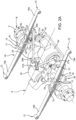
Figure 1A is a perspective view of a portion of vehicle equipped with a suspension system according to a first embodiment of a suspension system according to this invention; -
Figure 1B is a perspective view of a portion of a vehicle equipped with a suspension system according to a second embodiment of a suspension system according to this invention; -
Figure 2A is a perspective view of a first embodiment of a suspension system according to this invention; -
Figure 2B is a perspective view of a second embodiment of a suspension system according to this invention; -
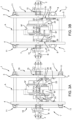
Figures 3A and 3B are plan views from above of the suspension systems inFigures 2A-2B ; -
Figures 4A and 4B are plan views from below of the suspension systems inFigures 2A-2B ; and -
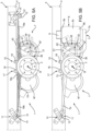
Figures 5A and 5B are side views of the suspension systems inFigures 2A-2B . -
Figures 1 and2 illustrate two different embodiments of asuspension system 1 to connect anaxle 2 of a commercial vehicle to itschassis 3. - The
chassis 3 comprises, as known, a pair ofside members suspension system 1 can be designed for a commercial vehicle comprising a front axle (not shown) and at least onerear axle 2. - It should be noted, in particular, how the
axle 2 has electric traction, i.e., is equipped with electric machines M', M" that are powered by at least one battery module (not illustrated) to provide torque to the wheels (not illustrated) supported by theaxle 2 or to receive electricity generated by the electric machines M', M" when the vehicle is braking. - Given the presence of these electric machines M', M", the
axle 2 extends in the space comprised, laterally, between theside members axle 2 that is transverse, in particular perpendicular, to the longitudinal axis A of the vehicle. - It should be noted, in particular, that the
suspension system 1 comprises aleft side 1" and a right side 1'. Since theleft side 1" and the right side 1' are symmetrically equal to the longitudinal axis A, for brevity, thesuspension system 1 will be described below by referring just to the right side 1' alone. - The two embodiments described below differ by the different type of longitudinal retaining element as described below.
- With reference to
Figures 2B ,3B ,4B ,5B , thesuspension system 1 comprises ametal cross member 7, or an elastic cross member, comprising afront portion 7a and arear portion 7b that extend along the longitudinal axis A. Themetal cross member 7 is connected to theaxle 2, as described below, in anintermediate portion 7c longitudinally comprised between the front andrear end portions - In particular, the
metal cross member 7 is shaped so that thefront portion 7 is vertically lower than therear portion 7b and theintermediate portion 7c, which are, instead, basically vertically aligned. In addition, as is clearer inFigure 4B , the front portion is also tilted in relation to the rear 7b and the intermediate 7c portions that are aligned. In particular, thefront portion 7a is tilted in relation to the axis A so that it is directed towards thecorresponding side member 4. - It should also be noted that the
metal cross member 7 is housed outside the space comprised by theside members front portion 7a that ends at thecorresponding side member 4. - The
metal cross member 7 preferably consists of a single piece, made of metal with a rectangular cross-section. More preferably, the thickness of this rectangular cross-section in the vertical direction is variable by a minimum at therear portion 7b and a maximum at thefront portion 7a. - Advantageously, the
front portion 7a is connected to thechassis 3, i.e., to theside member 4, via pneumatic suspension such as, for example, abellows 8 positioned in a vertical direction between thechassis 3 and themetal cross member 7. - In particular, the
bellows 8 comprises anupper portion 8a configured to be connected to thechassis 3, for example via abracket 9, and alower portion 8b that is connected, for example via a threaded element, to thecorresponding front portion 7a. As known, eachbellows 8 comprises an air bearing 8c supported by the upper andlower portions lower portions - Advantageously, the
rear portion 7b is connected to thechassis 3, i.e., to theside member 4, via amechanical coupling 11, advantageously a mechanical coupling of the type that moves between a hookedend portion 12 of therear portion 7b configured to be hinged in apin 13 that is integral with theside member 4. - The
metal cross member 7 is connected to theaxle 2 via aconnection group 15 comprising, preferably, at least oneplate 16 placed vertically between theaxle 2 and theintermediate portion 7c of themetal cross member 7. In the case illustrated, there is a first plate placed above theaxle 2 and a second plate placed below theaxle 2 between this and themetal cross member 7. - The
connection group 15 comprises, in addition,holding means 17 configured to exert a compression force between theaxle 2, the at least oneplate 16, and themetal cross member 7 so as to keep the latter connected together via friction. - In particular, the
holding means 17 may comprise two "U"shaped brackets 18 equipped with threaded ends configured to pass around theintermediate portion 7c of themetal cross member 7 and threaded elements configured to cooperate with these threaded ends to exert the compression force between the above-mentioned elements. - With reference to
Figures 2A ,3A ,4A ,5A , thesuspension system 1 comprises aleaf spring 19, advantageously of the semi-elliptical type, comprising afront portion 19a and arear portion 19b extending along the longitudinal axis A. Theleaf spring 19 is connected to theaxle 2, as described below, in anintermediate portion 19c longitudinally comprised between the front andrear portions - The rear and
front portions chassis 3, i.e., to theside member 4, via amechanical coupling 11, advantageously a mechanical coupling of the type that moves between a respective hookedend portion 12 configured to be hinged in apin 13 that is integral with theside member 4. More specifically, it should be noted how the hookedend portions 12 of the front andrear portions - In addition, it should be noted how the
mechanical coupling 11 between thefront portion 19a and theside member 4 comprises a mobile pin 13' dragged by a connectingrod 14 hinged to theside member 4. In particular, the connectingrod 14 is hinged to theside member 4 on the side opposite the mobile pin 13' so as to enable the rotation of the mobile pin 13' around an axis parallel to the axis B. - The
leaf spring 19 is, in addition, connected to theaxle 2 via aconnection group 15 that is similar to that of the first embodiment and, thus, not additionally described, for brevity. - It should be additionally noted how the
leaf spring 19 is housed entirely outside the space comprised by theside members - In both embodiments, the
suspension 1 also comprises ashock absorber 21 placed along the above-mentioned vertical direction between theaxle 2 and thechassis 3, i.e., theside member 4. In particular, theshock absorber 21 is inclined in relation to the vertical in relation to theside member 4/to the ground by an angle of approximately 45°. - The
shock absorber 21 is preferably a hydraulic shock absorber, i.e., a cylinder, comprising ahousing 21a that is supported by theside member 3 and arod 21b that is connected to theaxle 2. As known, therod 21b is configured to move inside thehousing 21a against the action of a fluid contained in thehousing 21a to dampen the relative movement between theside member 4 and theaxle 2. - The
rod 21b is connected between thechassis 2 and theside member 4 along the axis B in a portion comprised between the coupling with themetal cross member 7/leaf spring 19 and one of the electric machines M', while it is fixed to theside member 4, along the direction of the axis A in a portion corresponding to that of thefront portion 7a/19a of themetal cross member 7/leaf spring 19. - In particular, the
rod 21b is connected to theaxle 2 via ahinge 22 connection configured to enable a rotation of the end portion of therod 21b around an axis parallel to a transverse axis B. Thehousing 21a is connected, in contrast, to theside member 4 via ahinge 23 connection configured to enable a rotation of the end portion of thehousing 21a around an axis parallel to the axis B. - The
suspension system 1 also comprises atransverse retaining element 25 configured to support transverse movements that act between theaxle 2 and thechassis 3 but that enables a vertical movement between these latter elements. - In particular, the transverse retaining
element 25 comprises afirst arm 27 and asecond arm 28. Each of thearms front portion rear portion axle 2 and to aside member arm hinge 29 connection. - Specifically, the first and
second arm rear portions axle 2 along the axis B, while thefront portions second arm arms - Specifically, the
hinge 29 connections are made on correspondingflanges axle 2 and theside members flange 31 carried by theaxle 2 is placed between the electric machines M', M" along the axis A. - The
suspension system 1 also comprises astabilizer bar 35 configured to dampen any torque that acts between theaxle 2 and thechassis 3. - The
stabilizer bar 35 basically comprises (as shown better inFigures 4A/4B ) a segmented shape that is concave towards the electric machines M', M"; preferably, this segmented shape is symmetrical in relation to the longitudinal axis A. In addition, thestabilizer bar 35 is arranged below theaxle 2 and themetal cross member 7/leaf spring 19. - Going into more detail, the stabilizer bar comprises:
- a
central portion 35a extending parallel to the axis B for the extension of the electric machines along this axis, - a pair of
inclined portions 35b extending from the side ends of thecentral portion 35a and inclined in relation to the axis A, preferably by approximately 45°, - a pair of
intermediate portions 35c extending from the side end of theinclined portions 35b and parallel to the central portion extending at onecorresponding side member - a pair of
longitudinal portions 35d extending from the side end of theintermediate portions 35c parallel to and at the side members 4.5; - a pair of
end portions 35e extending from the rear end of thelongitudinal portions 35d, advantageously parallel to thecentral portion 35a. - The
stabilizer bar 35 is advantageously connected to theaxle 2 at theend portions 35e via amobile connection 36 and at thecorresponding side member intermediate portions 35d via aconnection group 38. - In particular, the
mobile connection 36 comprises ahinge 37, preferably made in one of theplates 16 of theconnection group 15. - The connection group 38 (more clearly visible in
Figures 2A /2B ,4A/4B ) is configured to make a rotating movement around an axis parallel to the transverse axis B and preferably comprises aconnection element 41 equipped with a lower end connected to the end portion via ahinge 42 and an upper end connected to thechassis 3 via anadditional hinge 42. The hinges 42 are both configured to enable a rotation around an axis parallel to the transverse axis B. - A
hinge 42 is preferably made between the upper end of theconnection element 41 and acorresponding side member other hinge 42 is made between the lower end of theconnection element 41 and theintermediate portion 35c of thetorsion bar 35. - In particular, it should be noted how the
upper hinge 42 is made on a portion vertically below the side member, so that, in a rest condition, theconnection element 41 is basically vertical to the ground. - It should also be noted that the
connection element 41 is placed, along the axis B, below theside member metal cross member 7/leaf spring 19, and theshock absorber 21. - It is clear that the
suspension system 1 may comprise additional elements not described here and designed to enable the assembly/arrangement of the elements mentioned above and not described for brevity. - The operation of the
suspension system 1 described above is the following. - During the movement of the vehicle, the at least one
axle 2 follows the roughness of the road and may move in relation to thechassis 3 of the vehicle. In particular, in addition, the torque for moving the vehicle is provided by at least one of the electric motors M', M" . - These movements are dampened by the
suspension system 1, in particular: - the vertical movements are dampened by the
shock absorbers 21 and by the pneumatic suspensions 8 (or, instead of the pneumatic suspension, by the leaf spring 19) . - the transverse movements are compensated for by the transverse retaining
element 25 and by themetal cross member 7/leaf spring 19; - the transverse movements are compensated for by the transverse retaining
element 25 and by thetorsional bar 35; and - the torque movements are compensated for by the
stabilizer bar 35. - In light of the above, the advantages of the suspension system described above, according to the invention, are clear.
- The
suspension system 1 proposed, in particular the position of thestabilizer bar 35 and its shape, enables the assembly of thesuspension 1, including in the case of anelectric axle 2, maintaining, at the same time, excellent mechanical properties. - In addition, the
suspension system 1 proposed is particularly compact since the majority of the elements are housed at the side members or outside the space comprised by them, leaving the space comprised by them for the housing of the electric machines M', M". - The peculiar arrangement of the
stabilizer bar 35 and its form make it possible to obtain a high oscillation thereof without interfering with the other suspension elements or with the electric motors. - In addition, the stabilizer bar can consist of a single piece, thus, via standard production systems; similarly, the
shock absorber 21 or the holding element 24 are standard elements like the hinges or supports mentioned. As a result, thesuspension system 1 is particularly cost-effective. - It is clear that alternations may be made to the suspension system that do not extend beyond the scope of protection defined by the claims.
- For example, this position and this shape of the elements of the
suspension 1 may vary within the limits of the claims attached. - In addition, the
suspension system 1 may be provided for front or rear axles configured as a traction or towing axle or as a standard axle. - The fastening means, the hinges and the connections shown and described may vary and be replaced with equivalent means.
Claims (15)
- A commercial vehicle comprising an electric drive axle (2) and a suspension system (1) for said axle (2), the chassis (3) of said commercial vehicle comprising a pair of side members (4, 5), said axle (2) extending along an axis transverse (B) with respect to a longitudinal axis (A) of said vehicle,said suspension system (1) comprising:• a longitudinal element (7; 19) comprising a front-end portion and a rear end portion (7a, 7b; 19a, 19b) along said longitudinal axis (A) each operatively connected to said chassis (3) and an intermediate portion (7c 19c) included between the latter and connected to said axle (2) ;• a shock absorber (21) operatively interposed between said axle (2) and said chassis (3);• a transverse retaining element (25) operatively interposed between the axle (2) and said chassis (3); and• a stabilizer bar (35) operatively interposed between said axle (2) and said chassis (3),
wherein said stabilizer bar (35) is arranged under said axle (2) and comprises a central portion (35a), a pair of end portions (35e) and a pair of intermediate portions (35c),said end portions (35e) being rotatably connected to said axle (2) and said intermediate portions (35c) being movably connected to said chassis (3). - - The vehicle according to claim 1, wherein said central portion (35a) is straight and parallel to said axis (B) .
- - The vehicle according to claim 1 or 2, in which said intermediate portions (35c) are straight and parallel to said central portion (35a).
- - The vehicle according to claim 1 to 3, in which said end portions (35e) are straight and parallel to said central portion (35a).
- - The vehicle according to one of claims 1 to 4, in which said chassis (3), said intermediate portions (35c) are arranged in correspondence with said side members (4, 5).
- - The vehicle according to one of claims 1 to 5, wherein said stabilizer bar (35) comprises a pair of inclined portions (35b) placed between said intermediate portions (35c) and said central portion (35a).
- - The vehicle according to one of claims 1 to 6, wherein said stabilizer bar (35) comprises a pair of longitudinal portions (35d) parallel to said longitudinal axis (A) and placed between said intermediate portions (35c) and said end portions (35e).
- - The vehicle according to one of the preceding claims, wherein said intermediate portion (7c; 19c) is connected to said axle (2) by means of a connection group (15), said connection group (15) comprising at least one plate (16) in contact with said axle (2) and holding means (17) configured to provide a compressive force between the axle (2), said at least one plate (16) and said longitudinal element (7; 19), said end portions (35e) of said stabilizer bar (35) being connected to a plate (16) placed under said axle (2).
- - The vehicle according to one of the preceding claims, in which said end portions (35e) are hinged to said axle (2).
- - The vehicle according to one of the preceding claims, in which said intermediate portions (35c) are connected to said chassis (3) by means of a connection assembly (38) comprises a connection element (41) provided with opposite ends respectively hinged by means of hinges (42) on said intermediate portions (35c) and on said chassis (3) .
- - The vehicle according to one of the preceding claims, wherein said longitudinal element comprises an elastic cross member (7) connected to said rear end (7b) by means of a mobile connection (11) and connected to said front end (7a) by means of a pneumatic suspension (8).
- - The vehicle according to claim 11, wherein said rear end (7b) is placed vertically above said axle (2) while said front end (7a) is placed vertically below said axle (2) .
- - The vehicle according to one of the preceding claims, wherein said longitudinal element comprises a leaf spring (19) connected to said front and rear ends (19a, 19b) by means of a movable connection (11).
- The vehicle according to any one of the preceding claims, wherein said shock absorber (21) comprises a hydraulic cylinder which is hinged through respective hinges (22, 23) at its ends on said chassis (3) and on said axle (2) .
- The vehicle according to any one of the preceding claims, wherein said transverse retaining element (25) comprises a first and a second arm (27, 28) comprising first ends connected to each other and hinged on said chassis (3) and second ends hinged each on the top of said axle (2), said hinges (29) allowing a movement of the respective ends around respective axes parallel to said transverse axis (B).
Applications Claiming Priority (1)
| Application Number | Priority Date | Filing Date | Title |
|---|---|---|---|
| IT102021000027863A IT202100027863A1 (en) | 2021-10-29 | 2021-10-29 | IMPROVED SUSPENSION SYSTEM OF A COMMERCIAL VEHICLE |
Publications (1)
| Publication Number | Publication Date |
|---|---|
| EP4173858A1 true EP4173858A1 (en) | 2023-05-03 |
Family
ID=80121704
Family Applications (1)
| Application Number | Title | Priority Date | Filing Date |
|---|---|---|---|
| EP22203501.6A Pending EP4173858A1 (en) | 2021-10-29 | 2022-10-25 | Suspension system of a commercial vehicle |
Country Status (2)
| Country | Link |
|---|---|
| EP (1) | EP4173858A1 (en) |
| IT (1) | IT202100027863A1 (en) |
Citations (8)
| Publication number | Priority date | Publication date | Assignee | Title |
|---|---|---|---|---|
| FR1381953A (en) * | 1963-02-23 | 1964-12-14 | Daimler Benz Ag | Wheel suspension, especially for the rear axle of automobile cars |
| US3885775A (en) * | 1974-01-24 | 1975-05-27 | Germain C Bolduc | Vehicle suspension device |
| JPH11321260A (en) * | 1998-05-11 | 1999-11-24 | Nhk Spring Co Ltd | Suspension rod |
| KR20020038076A (en) * | 2000-11-16 | 2002-05-23 | 류정열 | Vehicle stabilizer bar improvement |
| DE102005014231A1 (en) * | 2005-03-30 | 2006-10-05 | Daimlerchrysler Ag | motor vehicle |
| CN106240271A (en) * | 2016-08-19 | 2016-12-21 | 浙江吉利新能源商用车有限公司 | Air spring suspension systems and there is the vehicle of this suspension system |
| DE102019201731B3 (en) * | 2019-02-11 | 2020-03-12 | Audi Ag | Mounting arrangement for a stabilizer of a motor vehicle |
| US20210008969A1 (en) * | 2018-02-19 | 2021-01-14 | Axletech International Ip Holdings, Llc | Axle assembly for frame rail vehicles |
-
2021
- 2021-10-29 IT IT102021000027863A patent/IT202100027863A1/en unknown
-
2022
- 2022-10-25 EP EP22203501.6A patent/EP4173858A1/en active Pending
Patent Citations (8)
| Publication number | Priority date | Publication date | Assignee | Title |
|---|---|---|---|---|
| FR1381953A (en) * | 1963-02-23 | 1964-12-14 | Daimler Benz Ag | Wheel suspension, especially for the rear axle of automobile cars |
| US3885775A (en) * | 1974-01-24 | 1975-05-27 | Germain C Bolduc | Vehicle suspension device |
| JPH11321260A (en) * | 1998-05-11 | 1999-11-24 | Nhk Spring Co Ltd | Suspension rod |
| KR20020038076A (en) * | 2000-11-16 | 2002-05-23 | 류정열 | Vehicle stabilizer bar improvement |
| DE102005014231A1 (en) * | 2005-03-30 | 2006-10-05 | Daimlerchrysler Ag | motor vehicle |
| CN106240271A (en) * | 2016-08-19 | 2016-12-21 | 浙江吉利新能源商用车有限公司 | Air spring suspension systems and there is the vehicle of this suspension system |
| US20210008969A1 (en) * | 2018-02-19 | 2021-01-14 | Axletech International Ip Holdings, Llc | Axle assembly for frame rail vehicles |
| DE102019201731B3 (en) * | 2019-02-11 | 2020-03-12 | Audi Ag | Mounting arrangement for a stabilizer of a motor vehicle |
Also Published As
| Publication number | Publication date |
|---|---|
| IT202100027863A1 (en) | 2023-04-29 |
Similar Documents
| Publication | Publication Date | Title |
|---|---|---|
| CN104943490B (en) | Vehicle with single-wheel suspension and rear axle with single-wheel suspension and vehicles equipped accordingly | |
| CN109747359B (en) | Independent rear suspension for a motor vehicle having an electric drivetrain | |
| RU2508998C2 (en) | Automotive dual lead suspension with j-shape spring | |
| RU2259926C2 (en) | Vehicle solid axle suspension | |
| US6375203B1 (en) | Front air spring suspension with leading arm trailing and V-link | |
| CN104210321A (en) | Multilink rear axle for a motor vehicle | |
| US9010784B2 (en) | Suspension mechanism | |
| CN103660842B (en) | Leaf spring balanced suspension mechanism and engineering vehicle having same | |
| CN112368160A (en) | In-wheel three-arm suspension for vehicles | |
| CN109070671B (en) | Vehicle independent suspension with wheel-guiding leaf spring element made of fiber composite material | |
| CN109291747A (en) | motor vehicle | |
| US20110175316A1 (en) | Axle suspension | |
| AU2016303253A1 (en) | Pneumatic axle suspension for a rear axle of a vehicle | |
| US4763885A (en) | Planar spring | |
| EP1613490A1 (en) | Anti-roll leaf spring suspension | |
| US7753400B2 (en) | Multi-axle leaf spring suspension with compliant equalizer | |
| CN112566801B (en) | Suspension for vehicles | |
| CN1341059A (en) | Axle Suspension System of Automobile Rigid Axle | |
| CN100540342C (en) | Independent Suspension of Shuangrui Automobile | |
| EP4173858A1 (en) | Suspension system of a commercial vehicle | |
| EP4232305A1 (en) | Improved suspension system for a heavy vehicle | |
| CN201914036U (en) | Double-rear-axle linkage truck suspension | |
| EP4190601B1 (en) | Vehicle with an improved suspension system | |
| CN102114759A (en) | Dual-rear axle linkage truck suspension | |
| WO2022269461A1 (en) | Improved braket for a suspension system of a heavy vehicle |
Legal Events
| Date | Code | Title | Description |
|---|---|---|---|
| PUAI | Public reference made under article 153(3) epc to a published international application that has entered the european phase |
Free format text: ORIGINAL CODE: 0009012 |
|
| STAA | Information on the status of an ep patent application or granted ep patent |
Free format text: STATUS: THE APPLICATION HAS BEEN PUBLISHED |
|
| AK | Designated contracting states |
Kind code of ref document: A1 Designated state(s): AL AT BE BG CH CY CZ DE DK EE ES FI FR GB GR HR HU IE IS IT LI LT LU LV MC ME MK MT NL NO PL PT RO RS SE SI SK SM TR |
|
| STAA | Information on the status of an ep patent application or granted ep patent |
Free format text: STATUS: REQUEST FOR EXAMINATION WAS MADE |
|
| 17P | Request for examination filed |
Effective date: 20231030 |
|
| RBV | Designated contracting states (corrected) |
Designated state(s): AL AT BE BG CH CY CZ DE DK EE ES FI FR GB GR HR HU IE IS IT LI LT LU LV MC ME MK MT NL NO PL PT RO RS SE SI SK SM TR |
|
| STAA | Information on the status of an ep patent application or granted ep patent |
Free format text: STATUS: EXAMINATION IS IN PROGRESS |
|
| 17Q | First examination report despatched |
Effective date: 20241031 |