EP4173841A1 - Wire-spoke wheel - Google Patents
Wire-spoke wheel Download PDFInfo
- Publication number
- EP4173841A1 EP4173841A1 EP22195545.3A EP22195545A EP4173841A1 EP 4173841 A1 EP4173841 A1 EP 4173841A1 EP 22195545 A EP22195545 A EP 22195545A EP 4173841 A1 EP4173841 A1 EP 4173841A1
- Authority
- EP
- European Patent Office
- Prior art keywords
- hub
- wire
- spoke
- wheel
- cover member
- Prior art date
- Legal status (The legal status is an assumption and is not a legal conclusion. Google has not performed a legal analysis and makes no representation as to the accuracy of the status listed.)
- Withdrawn
Links
- 210000002445 nipple Anatomy 0.000 claims abstract description 92
- 230000002093 peripheral effect Effects 0.000 claims description 20
- 239000000463 material Substances 0.000 claims description 9
- 239000011347 resin Substances 0.000 claims description 7
- 229920005989 resin Polymers 0.000 claims description 7
- 238000010521 absorption reaction Methods 0.000 description 24
- 238000003780 insertion Methods 0.000 description 10
- 230000037431 insertion Effects 0.000 description 10
- 230000035939 shock Effects 0.000 description 10
- 238000006073 displacement reaction Methods 0.000 description 6
- 239000011324 bead Substances 0.000 description 4
- 230000007423 decrease Effects 0.000 description 4
- 238000012423 maintenance Methods 0.000 description 4
- 239000007769 metal material Substances 0.000 description 3
- 229910000838 Al alloy Inorganic materials 0.000 description 2
- XEEYBQQBJWHFJM-UHFFFAOYSA-N Iron Chemical compound [Fe] XEEYBQQBJWHFJM-UHFFFAOYSA-N 0.000 description 2
- 238000010586 diagram Methods 0.000 description 1
- 239000011796 hollow space material Substances 0.000 description 1
- 229910052742 iron Inorganic materials 0.000 description 1
Images





Classifications
-
- B—PERFORMING OPERATIONS; TRANSPORTING
- B60—VEHICLES IN GENERAL
- B60B—VEHICLE WHEELS; CASTORS; AXLES FOR WHEELS OR CASTORS; INCREASING WHEEL ADHESION
- B60B1/00—Spoked wheels; Spokes thereof
- B60B1/02—Wheels with wire or other tension spokes
-
- B—PERFORMING OPERATIONS; TRANSPORTING
- B60—VEHICLES IN GENERAL
- B60B—VEHICLE WHEELS; CASTORS; AXLES FOR WHEELS OR CASTORS; INCREASING WHEEL ADHESION
- B60B1/00—Spoked wheels; Spokes thereof
- B60B1/02—Wheels with wire or other tension spokes
- B60B1/04—Attaching spokes to rim or hub
- B60B1/042—Attaching spokes to hub
-
- B—PERFORMING OPERATIONS; TRANSPORTING
- B60—VEHICLES IN GENERAL
- B60B—VEHICLE WHEELS; CASTORS; AXLES FOR WHEELS OR CASTORS; INCREASING WHEEL ADHESION
- B60B7/00—Wheel cover discs, rings, or the like, for ornamenting, protecting, venting, or obscuring, wholly or in part, the wheel body, rim, hub, or tyre sidewall, e.g. wheel cover discs, wheel cover discs with cooling fins
- B60B7/0006—Wheel cover discs, rings, or the like, for ornamenting, protecting, venting, or obscuring, wholly or in part, the wheel body, rim, hub, or tyre sidewall, e.g. wheel cover discs, wheel cover discs with cooling fins for cycle wheels or similar
-
- B—PERFORMING OPERATIONS; TRANSPORTING
- B60—VEHICLES IN GENERAL
- B60B—VEHICLE WHEELS; CASTORS; AXLES FOR WHEELS OR CASTORS; INCREASING WHEEL ADHESION
- B60B1/00—Spoked wheels; Spokes thereof
- B60B1/02—Wheels with wire or other tension spokes
- B60B1/0215—Wheels with wire or other tension spokes characterised by specific grouping of spokes
-
- B—PERFORMING OPERATIONS; TRANSPORTING
- B60—VEHICLES IN GENERAL
- B60B—VEHICLE WHEELS; CASTORS; AXLES FOR WHEELS OR CASTORS; INCREASING WHEEL ADHESION
- B60B2900/00—Purpose of invention
- B60B2900/30—Increase in
- B60B2900/331—Safety or security
- B60B2900/3312—Safety or security during regular use
-
- B—PERFORMING OPERATIONS; TRANSPORTING
- B60—VEHICLES IN GENERAL
- B60Y—INDEXING SCHEME RELATING TO ASPECTS CROSS-CUTTING VEHICLE TECHNOLOGY
- B60Y2200/00—Type of vehicle
- B60Y2200/10—Road Vehicles
- B60Y2200/12—Motorcycles, Trikes; Quads; Scooters
-
- Y—GENERAL TAGGING OF NEW TECHNOLOGICAL DEVELOPMENTS; GENERAL TAGGING OF CROSS-SECTIONAL TECHNOLOGIES SPANNING OVER SEVERAL SECTIONS OF THE IPC; TECHNICAL SUBJECTS COVERED BY FORMER USPC CROSS-REFERENCE ART COLLECTIONS [XRACs] AND DIGESTS
- Y02—TECHNOLOGIES OR APPLICATIONS FOR MITIGATION OR ADAPTATION AGAINST CLIMATE CHANGE
- Y02T—CLIMATE CHANGE MITIGATION TECHNOLOGIES RELATED TO TRANSPORTATION
- Y02T10/00—Road transport of goods or passengers
- Y02T10/80—Technologies aiming to reduce greenhouse gasses emissions common to all road transportation technologies
- Y02T10/86—Optimisation of rolling resistance, e.g. weight reduction
Definitions
- the present disclosure relates to a wire-spoke wheel.
- wire-spoke wheels As a type of wheels for use in motorcycles and other vehicles, wire-spoke wheels are known in which a rim and a hub are linked by a plurality of wire spokes. Wire-spoke wheels have the advantage of good shock absorption.
- Patent Document 1 A wire-spoke wheel is disclosed in Japanese Laid-Open Patent Publication No. 2012-232658 (hereinafter "Patent Document 1"), for example.
- Patent Document 1 a head at one end of each wire spoke is secured at the hub side, while a threaded portion at the other end of the wire spoke is fastened at the rim side by a nipple.
- the present disclosure has been made in view of the above problem, and an objective thereof is, in a wire-spoke wheel having a configuration in which one end of each wire spoke is fastened to the hub side by a nipple, to prevent the nipple from falling off.
- a wire-spoke wheel comprising:
- the hub-end (second end) of each wire spoke is fastened to the hub via the nipple. Because the wire-spoke wheel according to an embodiment of the present invention includes the cover member being attached to the hub and covering the heads of the nipples, the nipples are unlikely to fall off even when the nipples become loose. Moreover, the cover member being attached to the hub can provide for improved design.
- the interval between the cover member and the head of nipple is set so that the engagement between the nipple and the wire spoke is not lost, it is even less likely for the nipples to fall off.
- the interval between the cover member and the head of the nipple may be zero, that is, the cover member may be in contact with the head of the nipple.
- wire-spoke wheel of Claims 1 or 2 wherein, in a plan view as viewed along a wheel axis direction, regarding each wire spoke,
- a wire-spoke wheel may have a configuration that allows the wire spokes to be longer than conventional. Specifically, in a plan view as viewed along a wheel axis direction, the following may be assumed regarding each wire spoke: an imaginary line connecting the rim-end (first end) of the wire spoke and the center of the hole (wheel-shaft insertion hole) in the hub defines a first imaginary line; an imaginary line being orthogonal to the first imaginary line and passing through a center of the hole defines a second imaginary line; and the second imaginary line divides the hub into two regions.
- the hub-end (second end) of the wire spoke may be connected to the hub in the second region of the hub.
- each wire spoke is disposed so as to extend from the rim to the hub and beyond the second imaginary line
- the wire spokes can be made longer than conventional, whereby energy absorption by the wire spokes increases, thus resulting in an improved shock absorption. Therefore, a straddled vehicle including a wire-spoke wheel with such a configuration provides better riding comfort on poor terrain and uneven road surfaces. As energy absorption increases, the input occurring at the fastening site of each wire spoke decreases, which reduces loosening of the fastening site and reduces the frequency of maintenance.
- each of the plurality of wire spokes has a length which is 60% or more of the rim diameter.
- each wire spoke penetrates the interior of the hub from a portion to another portion of the outer cylindrical portion of the hub allows the hub-end (second end) of the wire spoke to be connected to the hub in the second region.
- the wire-spoke wheel of Claims 5 wherein the cover member is an annular band, and is attached to an outer peripheral surface of the outer cylindrical portion of the hub.
- the cover member may be an annular band, for example, which may be attached to the outer peripheral surface of the outer cylindrical portion of the hub.
- the hub which includes the inner cylindrical portion and the flange portion, adopting the configuration where, e.g., the second end of each wire spoke is connected to the hub at the inner subportion of the flange portion allows the hub-end (second end) of the wire spoke to be connected to the hub in the second region.
- the cover member When the wire spokes are fastened to the hub at the flange portion, the cover member may have a disk shape, for example, which is attached to the flange portion of the hub.
- a rubber or a resin material can be suitably used, for example.
- the nipple in a wire-spoke wheel having a configuration in which one end of each wire spoke is fastened to the hub side by a nipple, the nipple can be prevented from falling off.
- FIG. 1 and FIG. 2 are a perspective view and a side view, respectively, schematically showing the wheel 100.
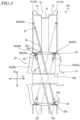
- FIG. 3 is a cross-sectional view schematically showing the wheel 100, illustrating a cross section that is parallel to a wheel axis direction D1 and a wheel radius direction D2.
- one side along the wheel axis direction D1 (the right side in FIG. 3 ) will be regarded as the right side, whereas the other side (the left side in FIG. 3 ) will be regarded as the left side.
- the wheel 100 includes a rim 10, a hub 20, and a plurality of wire spokes 30.
- the rim 10 has an annular shape, extending in a wheel circumference direction D3. A tire is mounted on the rim 10.
- the rim 10 is made of a metal material (e.g., an aluminum alloy) .
- the rim 10 includes a pair of flange portions 11, a well portion 12, and a pair of bead seat portions 13.
- the pair of flange portions 11 are located at both ends of the wheel axis direction D1 of the rim 10. Regarding the pair of flange portions 11, a flange portion 11A that is located on the right side of the rim 10 will be referred to as the "right flange portion”, whereas a flange portion 11B that is located on the left side of the rim 10 will be referred to as the "left flange portion”.
- the right flange portion 11A and the left flange portion 11B each extend outward along the wheel radius direction D2.
- the well portion 12 is located in the middle of the wheel axis direction D1 of the rim 10.
- the well portion 12 is dented inward along the wheel radius direction D2.
- the bead seat portions 13 are located between the right flange portion 11A and the well portion 12, and between the left flange portion 11A and the well portion 12.
- the bead seat portions 13 are portions that support bead portions of the tire.
- the hub 20 is located in the center of the wheel 100.
- the hub 20 includes a hole (wheel-shaft insertion hole) 20a through which a wheel shaft is inserted.
- a direction that is parallel to the center axis of the wheel-shaft insertion hole 20a is the wheel axis direction D1.
- the hub 20 is made of a metal material (e.g., an aluminum alloy).
- the hub 20 includes an inner cylindrical portion 21, an outer cylindrical portion 22, and an interconnecting portion 23.
- the inner cylindrical portion 21 is a barrel-shaped portion defining the wheel-shaft insertion hole 20a.
- the outer cylindrical portion 22 is a barrel-shaped portion being located outward of the inner cylindrical portion 21 along the wheel radius direction D2 and surrounding the inner cylindrical portion 21.
- the interconnecting portion 23 is a portion that connects the inner cylindrical portion 21 with the outer cylindrical portion 22.
- the interconnecting portion 23 includes a right interconnecting portion 23a that is located on the right side of the hub 20 and a left interconnecting portion 23b that is located on the left side of the hub 20.
- the right interconnecting portion 23a extends radially from the right end of the inner cylindrical portion 21 to the right end of the outer cylindrical portion 22.
- the left interconnecting portion 23b extends radially from the left end of the inner cylindrical portion 21 to the left end of the outer cylindrical portion 22.
- the shape of the interconnecting portion 23 is not limited to the illustrated example.
- the right interconnecting portion 23a and the left interconnecting portion 23b may each be shaped as a disk.
- the region of the hub 20 that is surrounded by the inner cylindrical portion 21, the outer cylindrical portion 22, and the interconnecting portion 23 is a hollow space.
- the hub 20 has a hollow structure.
- the plurality of wire spokes 30 link the rim 10 and the hub 20 together.
- the wire spokes 30 are made of a metal material (e.g., iron).
- the wheel 100 includes 32 wire spokes 30; however, the number of wire spokes 30 is of course not limited thereto.
- an end 30a that is connected to the rim 10 will be referred to as the "first end” or the "rim-end”
- an end 30b that is connected to the hub 20 will be referred to as the "second end” or the "hub-end”.
- the wheel 100 further includes a plurality of nipples 40 respectively fastening the respective hub-ends 30b of the wire spokes 30 to the hub 20.
- FIG. 4 and FIG. 5 are plan views showing a wire spoke 30 and a nipple 40, respectively.
- a spoke head 30h with an increased diameter is formed at the rim-end 30a of the wire spoke 30, whereas an external thread 30s is formed at the hub-end 30b.
- the nipple 40 includes a stem 41 and a head 42 that is provided at one end of the stem 41.
- the stem 41 has a barrel shape, with an internal thread 41s being formed on the inner peripheral surface of the stem 41.
- the flange portions 11 of the rim 10 include spoke holes 19 through which the wire spokes 30 can be inserted, such that the rim-ends 30a of the wire spokes 30 are secured to the corresponding flange portions 11 of the rim 10 via the spoke heads 30h.
- the hub-ends 30b of the wire spokes 30 are fastened to the outer cylindrical portion 22 of the hub 20 as their external threads 30s are screwed onto the internal threads 41s of the nipples 40.
- the wheel 100 further includes at least one (e.g., two in the illustrated example) cover member(s) 50 being attached to the hub 20.
- at least one e.g., two in the illustrated example
- cover member(s) 50 being attached to the hub 20.
- a cover member 50A that is located on the right side may be referred to as the right cover member
- a cover member 50B that is located on the left side may be referred to as the left cover member.
- the right cover member 50A covers the heads 42 of some of the plurality of nipples 40 (specifically, a half of the nipples 40).
- the left cover member 50B covers the heads 42 of the other nipples 40.
- FIG. 6 is a perspective view showing the wheel 100, from which the cover members 50 have been removed.
- FIG. 7 is a perspective view schematically showing a cover member 50.
- the cover member (s) 50 is an annular band(s).
- the cover member(s) 50 is made of a rubber or a resin material, for example.
- the cover members 50 are attached to the outer peripheral surface of the outer cylindrical portion 22 of the hub 20.
- a pair of grooves 22e and 22f extending along the wheel circumference direction D3 are formed on the outer peripheral surface of the outer cylindrical portion 22.
- the cover members 50 are fitted in the grooves 22e and 22f. More specifically, the right cover member 50A is fitted in the right groove 22e, whereas the left cover member 50B is fitted in the left groove 22f.
- the hub-ends 30b of the wire spokes 30 are fastened to the hub 20 via the nipples 40. Because the wheel 100 according to the present embodiment includes the cover members 50, which cover the heads 42 of the nipples 40 by being attached to the hub 20, the nipples 40 are unlikely to fall off even when the nipples 40 become loose.
- cover member(s) 50 being attached to the hub 20 can provide for improved design.
- the specific shape of the cover member(s) 50 is not limited to what is illustrated in FIG. 7 , and there is no particular limitation as to the width, thickness, etc., of the cover member(s) 50.
- FIG. 7 illustrates an example where the cover member(s) 50 has a constant (identical) width w across the entire cover member(s) 50, the width w of the cover member(s) 50 does not need to be constant.
- the wheel 100 has a configuration that allows the wire spokes 30 to be longer than conventional.
- this configuration will be specifically described.
- each wire spoke 30 will be discussed in a plan view as viewed along the wheel axis direction D1.
- FIG. 8 shows a side of the wheel 100 in a plan view drawn with particular attention to a certain wire spoke 30 (i.e., a wire spoke denoted as "30_F" in FIG. 8 ).
- an imaginary line L1 connecting the rim-end (first end) 30a of the wire spoke 30 and the center of the wheel-shaft insertion hole 20a defines a "first imaginary line”
- an imaginary line L2 being orthogonal to the first imaginary line L1 and passing through the center of the wheel-shaft insertion hole 20a defines a "second imaginary line”
- the second imaginary line L2 divides the hub 20 into two regions R1 and R2.
- one R1 of the two regions R1 and R2 that is located closer to the rim-end (first end) 30a of the wire spoke 30 defines a "first region", while the other region R2 defines a "second region”.
- the hub-end (second end) 30b of the wire spoke 30 is connected to the hub 20 in the second region R2 of the hub 20. More specifically, as shown in FIG. 3 , the wire spoke 30 penetrates the interior of the hub 20 from a portion (hereinafter referred to as a "spoke introduction site") 22a to another portion (hereinafter referred to as a "spoke connection site”) 22b of the outer cylindrical portion 22 of the hub 20.
- openings 22o through which the wire spokes 30 are passed are formed.
- the openings 22o are located in substantially the middle of the outer cylindrical portion 22 of the hub 20 along the wheel axis direction D1. Therefore, it can be said that the rim-ends 30a of the wire spokes 30 are located outward of the openings 22o along the wheel axis direction D1.
- four wire spokes 30 are passed through one opening 22o in the illustrated example, the relationship between the number of openings 22o and the number of wire spokes 30 is not limited thereto.
- the shape of each opening 22o is not limited to the illustrated example, either.
- FIG. 9 is a cross-sectional view showing the neighborhood of a spoke connection site 22b.
- a nipple hole 22c through which the stem 41 of the nipple 40 is inserted, and a recess 22d, which is continuous with the nipple hole 22c and in which the head 42 of the nipple 40 is accommodated, are formed at the spoke connection site 22b.
- the spoke connection site 22b corresponding to each wire spoke 30 is located in the groove 22e or 22f formed in the outer peripheral surface of the outer cylindrical portion 22.
- a half of the plurality of wire spokes 30 have their rim-ends 30a connected to the right flange portion 11A and their hub-ends 30b connected to a spoke connection site 22b in the left groove 22f.
- the other half of the wire spokes 30 have their rim-ends 30a connected to the left flange portion 11B and their hub-ends 30b connected to a spoke connection site 22b in the right groove 22e.
- each wire spoke 30 is connected to the hub 20 in the second region R2 of the hub 20.
- each wire spoke 30 is disposed so as to extend from the rim 10 to the hub 20 and beyond the second imaginary line L2.
- the wire spokes 30 can be made longer than conventional, whereby energy absorption by the wire spokes 30 increases, thus resulting in an improved shock absorption. Therefore, a straddled vehicle including the wheel 100 according to the present embodiment provides better riding comfort on poor terrain and uneven road surfaces. As energy absorption increases, the input occurring at the fastening site of each wire spoke 30 decreases, which reduces loosening of the fastening site and reduces the frequency of maintenance.
- the rim diameter is the nominal diameter of the rim as specified in various industrial standards.
- Example 1 which does not employ the above configuration (i.e., the hub-end 30b of each wire spoke 30 is connected to the hub 20 in the first region R1 of the hub 20) and Example 2, which employs the above configuration (i.e., the hub-end 30b of each wire spoke 30 is connected to the hub 20 in the second region R2 of the hub 20).
- the specifications of Examples 1 and 2 are as indicated in Table 1 below. [Table 1] Example 1 Example 2 number of spokes 32 32 spoke diameter [mm] 4.0 4.0 spoke length [mm] 200 300 rim diameter [Inch] 17 17 (spoke length /rim diameter) ⁇ 100[%] 46 69
- FIG. 10 is a graph showing a relationship (load-displacement curve) between the load acting on each wire spoke and the displacement of the wire spoke, with respect to Examples 1 and 2.
- the area of the region enclosed by each load-displacement curve corresponds to energy absorption.
- each wire spoke breaks (i.e., the load equals zero) at a certain load F.
- each wire spoke 30 penetrates the interior of the hub 20 from a portion (spoke introduction site 22a) to another portion (spoke connection site 22b) of the outer cylindrical portion 22 of the hub 20 allows the hub-end 30b of the wire spoke 30 to be connected to the hub 30 in the second region R2.
- FIG. 9 shows an example where the cover member 50 and the head 42 of the nipple 40 covered by the cover member 50 are spaced apart by a predetermined interval s.
- the interval s between the cover member 50 and the head 42 of the nipple 40 is set so that the engagement between the nipple 40 and the corresponding wire spoke 30 is not lost (i.e., so that the head 42 of the nipple 40 will abut with the inner peripheral surface 50a of the cover member 50 before the engagement is lost) .
- the interval s between the cover member 50 and the head 42 of the nipple 40 may be zero, that is, the cover member 50 may be in contact with the head 42 of the nipple 40.
- the rim-ends 30a of the wire spokes 30 are secured to the flange portions 11 of the rim 10 via the spoke heads 30h.
- the wire spoke 30 may move toward the outer side along the wheel radius direction D2. In that case, however, the rim-end 30a of the wire spoke 30 will abut against the tire 2, so that the wire spoke 30 will not drop to the outer side.
- setting of the interval s between the cover member 50 and the head 42 of the nipple 40 is preferably made so that the engagement between the nipple 40 and the corresponding wire spoke 30 is not lost while also taking the margin of movement of the wire spoke 30 to the outer side into consideration.
- the present embodiment illustrates an example where the grooves 22e and 22f are formed in the outer peripheral surface of the outer cylindrical portion 22 of the hub 20, the groove 22e and/or the groove 22f may not be formed in the outer peripheral surface of the outer cylindrical portion 22.
- FIG. 12 and FIG. 13 are side views schematically showing the wheel 200.
- FIG. 14 is a cross-sectional view schematically showing the wheel 200, illustrating a cross section that is parallel to the wheel axis direction D1 and the wheel radius direction D2.
- the wheel 200 includes a rim 10, a hub 20', and a plurality of wire spokes 30. Moreover, the wheel 200 includes a plurality of nipples 40 and at least one (e.g., two herein) cover member(s) 50'. FIG. 13 and FIG. 14 illustrate a state where the cover members 50' have been removed.
- the hub 20' of the wheel 200 according to the present embodiment lacks the hollow structure of the hub 20 of the wheel 100 according to Embodiment 1.
- the hub 20' includes an inner cylindrical portion 21 and a pair of flange portions 24.
- the inner cylindrical portion 21 is a barrel-shaped portion defining a wheel-shaft insertion hole 20a.
- the pair of flange portions 24 are portions extending outward along the wheel radius direction D2 from the inner cylindrical portion 21.
- the pair of flange portions 24 include a right flange portion 24A located on the right side and a left flange portion 24B located on the left side.
- Each of the right flange portion 24A and the left flange portion 24B includes a subportion (hereinafter referred to as the "outer peripheral subportion") 24a defining the outer periphery of the flange portion 24 and a subportion (hereinafter referred to as the “inner subportion”) 24b located inward of the outer peripheral subportion 24a along the wheel radius direction D2, and presents a dish shape in the illustrated example.
- Each of the plurality of nipples 40 fastens the hub-end 30b of the corresponding wire spoke 30 to the hub 20'.
- a plurality of bosses 24d are provided on the inner subportion 24b of each flange portion 24, with a nipple hole 24c being provided (through which the stem 41 of a nipple 40 is inserted).
- the hub-ends 30b of the wire spokes 30 are fastened to the flange portions 24 of the hub 20' by the nipples 40.
- the cover members 50' are attached to the hub 20.
- FIG. 12 between the two cover members 50', only the cover member that is located on the right side (right cover member) 50A' is shown, while the cover member that is located on the left side (left cover member) is not shown.
- the right cover member 50A' covers the heads 42 of some of the plurality of nipples 40 (specifically, a half of the nipples 40).
- the left cover member (not shown) covers the heads 42 of the other nipples 40.
- FIG. 15 is a side view showing the neighborhood of the hub 20' of the wheel 200.
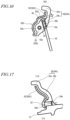
- FIG. 16 and FIG. 17 are cross-sectional views along line 16A-16A' and line 17A-17A', respectively, in FIG. 15 .
- each cover member 50' has a disk shape.
- each cover member 50' includes a plurality of protrusions 50b' corresponding to the plurality of bosses 24d of the flange portions 24.
- the cover members 50' are made of a resin material, for example.
- the right cover member 50A' is attached to the right flange portion 24A of the hub 20', while the left cover member (not shown) is attached to the left flange portion 24B of the hub 20'.
- each cover member 50' and each flange portion 24 bolt holes 50e' and 24e are formed, respectively, as shown in FIG. 17 , for example.
- the cover member 50' is attached to the flange portion 24 with a bolt 52. Note that the manner of attachment of the cover member 50' to the flange portion 24 is not limited to fastening with a bolt 52.
- the cover member 50' covers the heads 42 of the nipples 40.
- the hub-end 30b of each wire spoke 30 is fastened to the hub 20' via a nipple 40. Because the wheel 200 according to the present embodiment includes the cover members 50' being attached to the hub 20' and covering the heads 42 of the nipples 40, the nipples 40 are unlikely to fall off even when the nipples 40 become loose.
- cover member(s) 50' being attached to the hub 20' can provide for improved design.
- the specific shape of cover member(s) 50' is not limited to what is illustrated in FIG. 15 and the like, there is no particular limitation as to the thickness, shape, etc., of the cover member(s) 50'.
- FIG. 16 shows an example where the cover member 50' and the head 42 of the nipple 40 covered by the cover member 50' are spaced apart by a predetermined interval s.
- the interval s between the cover member 50' and the head 42 of the nipple 40 is preferably set so that the engagement between the nipple 40 and the corresponding wire spoke 30 is not lost (i.e., the head 42 of the nipple 40 will abut with an inner surface 50a' of the cover member 50' before the engagement is lost). This makes it even less likely for the nipples 40 to fall off.
- the interval s between the cover member 50' and the head 42 of the nipple 40 may be zero, that is, the cover member 50' may be in contact with the head 42 of the nipple 40.
- setting of the interval s between the cover member 50' and the head 42 of the nipple 40 is preferably made so that the engagement between the nipple 40 and the corresponding wire spoke 30 is not lost while also taking the margin of movement of the wire spoke 30 to the outer side into consideration.
- FIG. 18 shows a side of the wheel 200 in a plan view drawn with particular attention to a certain wire spoke 30 (i.e., a wire spoke denoted as "30_F" in FIG. 18 ).
- an imaginary line L1 connecting the rim-end 30a of the wire spoke 30 and the center of the wheel-shaft insertion hole 20a defines a "first imaginary line”
- an imaginary line L2 being orthogonal to the first imaginary line L1 and passing through the center of the wheel-shaft insertion hole 20a defines a "second imaginary line”
- the second imaginary line L2 divides the hub 20' into two regions R1 and R2. It is further assumed that one R1 of the two regions R1 and R2 that is located closer to the rim-end 30a of the wire spoke 30 of interest defines a "first region” and that the other region R2 defines a "second region”.
- the hub-end 30b of each wire spoke 30 is connected to the hub 20' in the second region R2 of the hub 20'. More specifically, the hub-end 30b of each wire spoke 30 is connected to the hub 20' at the inner subportion 24b of the flange portion 24.
- each wire spoke 30 When viewed in a plan view from the wheel axis direction D1, each wire spoke 30 extends from its rim-end 30a to its hub-end 30b, so as to pass inward of the hub-end 30b of at least another wire spoke 30 (i.e., inward along the wheel radius direction D2 ) .
- the wire spoke 30_F of particular interest in FIG. 18 extends so as to pass inward of another boss 24d (i.e., a boss 24d located at the boundary between the first region R1 and the second region R2) that is located to the right of the boss 24d to which the hub-end 30b of the wire spoke 30_F is connected.
- a half of the plurality of wire spokes 30 have their rim-ends 30a connected to the right flange portion 11A of the rim 10 and their hub-ends 30b connected to the left flange portion 24B of the hub 20'.
- the other half of the wire spokes 30 have their rim-ends 30a connected to the left flange portion 11B of the rim 10 and their hub-ends 30b connected to the right flange portion 24A of the hub 20'.
- each wire spoke 30 is connected to the hub 20' in the second region R2 of the hub 20'.
- each wire spoke 30 is disposed so as to extend from the rim 10 to the hub 20' and beyond the second imaginary line L2.
- the wire spokes 30 can be made longer than conventional, whereby energy absorption by the wire spokes 30 increases, thus resulting in an improved shock absorption. Therefore, a straddled vehicle including the wheel 200 according to the present embodiment provides better riding comfort on poor terrain and uneven road surfaces. As energy absorption increases, the input occurring at the fastening site of each wire spoke 30 decreases, which reduces loosening of the fastening site and reduces the frequency of maintenance.
- the hub 20' which includes the inner cylindrical portion 21 and the pair of flange portions 24, adopting the configuration where, e.g., the hub-end 30b of each wire spoke 30 is connected to the hub 20' at the inner subportion 24b of the flange portion 24 allows the hub-end 30b of the wire spoke 30 to be connected to the hub 20' in the second region R2.
- Embodiments 1 and 2 has illustrated a configuration in which the hub-end 30b of each wire spoke 30 is connected to the hub 20, 20' in the second region R2 of the hub 20, 20', embodiments of the present invention are not limited to such a configuration.
- the hub-end 30b of each wire spoke 30 may be connected to the hub 20, 20' in the first region R1 of the hub 20, 20'.
- a wire-spoke wheel 100, 200 includes: an annular rim 10; a hub 20, 20' having a hole 20a in which a wheel shaft is inserted; a plurality of wire spokes 30 linking the rim 10 and the hub 20, 20' together, the plurality of wire spokes 30 each including a first end 30a that is connected to the rim 10 and a second end 30b that is connected to the hub 20, 20'; a plurality of nipples 40 respectively fastening the respective second ends 30b of the plurality of wire spokes 30 to the hub 20, 20'; and a cover member 50, 50' being attached to the hub 20, 20' and covering a head 42 or heads 42 of at least a part of the plurality of nipples 40.
- the hub-end (second end) 30b of each wire spoke 30 is fastened to the hub 20, 20' via the nipple 40.
- the wire-spoke wheel 100, 200 according to an embodiment of the present invention includes the cover member 50, 50' being attached to the hub 20, 20' and covering the heads 42 of the nipples 40, the nipples 40 are unlikely to fall off even when the nipples 40 become loose.
- the cover member 50, 50' being attached to the hub 20, 20' can provide for improved design.
- an interval s between the cover member 50, 50' and a head 42 of the nipple 40 or each of the nipples 40 covered by the cover member 50, 50' is set so that so that the engagement between the nipple 40 and the corresponding wire spoke 30 is not lost.
- interval s between the cover member 50, 50' and the head 42 of each nipple 40 is set so that the engagement between the nipple 40 and the wire spoke 30 is not lost, it is even less likely for the nipples 40 to fall off.
- the interval s between the cover member 50, 50' and the head 42 of the nipple 40 may be zero, that is, the cover member 50, 50' may be in contact with the head 42 of the nipple 40.
- an imaginary line L1 connecting the first end 30a of the wire spoke 30 and a center of the hole 20a defines a first imaginary line; an imaginary line L2 being orthogonal to the first imaginary line L1 and passing through a center of the hole 20a defines a second imaginary line; and when the hub 20, 20' is divided into two regions R1 and R2 by the second imaginary line L2, one R1 of the two regions R1 and R2 that is located closer to the first end 30a of the wire spoke 30 defines a first region and the other R2 of the two regions R1 and R2 defines a second region, wherein the second end 30b of the wire spoke 30 is connected to the hub 20, 20' in the second region R2 of the hub 20, 20'.
- a wire-spoke wheel 100, 200 may have a configuration that allows the wire spokes 30 to be longer than conventional.
- each wire spoke 30 an imaginary line L1 connecting the rim-end (first end) 30a of the wire spoke 30 and the center of the hole (wheel-shaft insertion hole) 20a in the hub 20, 20' defines a first imaginary line; an imaginary line L2 being orthogonal to the first imaginary line L1 and passing through the center of the hole 20a defines a second imaginary line; and the second imaginary line L2 divides the hub 20, 20' into two regions R1, R2.
- the hub-end (second end) 30b of the wire spoke 30 may be connected to the hub 20, 20' in the second region R2 of the hub 20, 20'.
- each wire spoke 30 is disposed so as to extend from the rim 10 to the hub 20, 20' and beyond the second imaginary line L2
- the wire spokes 30 can be made longer than conventional, whereby energy absorption by the wire spokes 30 increases, thus resulting in an improved shock absorption. Therefore, a straddled vehicle including a wire-spoke wheel 100, 200 with such a configuration provides better riding comfort on poor terrain and uneven road surfaces. As energy absorption increases, the input occurring at the fastening site of each wire spoke 30 decreases, which reduces loosening of the fastening site and reduces the frequency of maintenance.
- each of the plurality of wire spokes 30 has a length which is 60% or more of the rim diameter.
- the hub 20 includes an inner cylindrical portion 21 defining the hole 20a, an outer cylindrical portion 22 being located outward of the inner cylindrical portion 21 along the wheel radius direction D2 and surrounding the inner cylindrical portion 21, and an interconnecting portion 23 connecting the inner cylindrical portion 21 and the outer cylindrical portion 22; and each of the plurality of wire spokes 30 penetrates the interior of the hub 20 from a portion 22a to another portion 22b of the outer cylindrical portion 22 of the hub 20, and is fastened to the hub 20 at the other portion 22b.
- each wire spoke 30 penetrates the interior of the hub 20 from a portion 22a to another portion 22b of the outer cylindrical portion 22 of the hub 20 allows the hub-end (second end) 30b of the wire spoke 30 to be connected to the hub 20 in the second region R2.
- the cover member 50 is an annular band, and is attached to an outer peripheral surface of the outer cylindrical portion 22 of the hub 20.
- the cover member 50 may be an annular band, for example, which may be attached to the outer peripheral surface of the outer cylindrical portion 22 of the hub 20.
- the hub 20' includes an inner cylindrical portion 21 defining the hole 20a and a flange portion 24 extending outward along the wheel radius direction D2 from the inner cylindrical portion 21;
- the flange portion 24 includes an outer peripheral subportion 24a, and an inner subportion 24b that is located inward of the outer peripheral subportion 24a along the wheel radius direction D2; and the second end 30b or ends 30b of at least a part of the plurality of wire spokes 30 is or are connected to the hub 20' in the inner subportion 24b of the flange portion 24.
- the hub 20' which includes the inner cylindrical portion 21 and the flange portion 24, adopting the configuration where, e.g., the second end 30b of each wire spoke 30 is connected to the hub 20' at the inner subportion 24b of the flange portion 24 allows the hub-end (second end) 30b of the wire spoke 30 to be connected to the hub 20' in the second region R2.
- the cover member 50' has a disk shape, and is attached to the flange portion 24 of the hub 20'.
- the cover member 50' may have a disk shape, for example, which is attached to the flange portion 24 of the hub 20'.
- the cover member 50, 50' may be made of a rubber or a resin material.
- a rubber or a resin material can be suitably used, for example.
- a wire-spoke wheel having a configuration in which one end of each wire spoke is fastened to the hub side by a nipple, the nipple can be prevented from falling off.
- a wire-spoke wheel according to an embodiment of the present invention can be suitably used for various straddled vehicles such as motorcycles.
Landscapes
- Engineering & Computer Science (AREA)
- Mechanical Engineering (AREA)
- Tires In General (AREA)
Abstract
Description
- The present disclosure relates to a wire-spoke wheel.
- As a type of wheels for use in motorcycles and other vehicles, wire-spoke wheels are known in which a rim and a hub are linked by a plurality of wire spokes. Wire-spoke wheels have the advantage of good shock absorption.
- A wire-spoke wheel is disclosed in
Japanese Laid-Open Patent Publication No. 2012-232658 Patent Document 1"), for example. In the wire-spoke wheel disclosed inPatent Document 1, a head at one end of each wire spoke is secured at the hub side, while a threaded portion at the other end of the wire spoke is fastened at the rim side by a nipple. - Contrary to the configuration disclosed in
Patent Document 1, a configuration may be possible in which the head of each wire spoke is secured to the rim side and the threaded portion of each wire spoke is fastened to the hub side by a nipple. In such a configuration, however, vibration during travel and the like may loosen the nipple, allowing it to fall off the wheel. - The present disclosure has been made in view of the above problem, and an objective thereof is, in a wire-spoke wheel having a configuration in which one end of each wire spoke is fastened to the hub side by a nipple, to prevent the nipple from falling off.
- The present specification discloses wire-spoke wheels as recited in the following Claims.
- A wire-spoke wheel comprising:
- an annular rim;
- a hub having a hole in which a wheel shaft is inserted;
- a plurality of wire spokes linking the rim and the hub together, the plurality of wire spokes each including a first end that is connected to the rim and a second end that is connected to the hub;
- a plurality of nipples respectively fastening the respective second ends of the plurality of wire spokes to the hub; and
- a cover member being attached to the hub and covering a head or heads of at least a part of the plurality of nipples.
- In a wire-spoke wheel according to an embodiment of the present invention, the hub-end (second end) of each wire spoke is fastened to the hub via the nipple. Because the wire-spoke wheel according to an embodiment of the present invention includes the cover member being attached to the hub and covering the heads of the nipples, the nipples are unlikely to fall off even when the nipples become loose. Moreover, the cover member being attached to the hub can provide for improved design.
- The wire-spoke wheel of
Claims 1, wherein an interval between the cover member and a head of the nipple or each of the nipples covered by the cover member is set so that engagement between the nipple and the corresponding wire spoke is not lost. - Because the interval between the cover member and the head of nipple is set so that the engagement between the nipple and the wire spoke is not lost, it is even less likely for the nipples to fall off. The interval between the cover member and the head of the nipple may be zero, that is, the cover member may be in contact with the head of the nipple.
- The wire-spoke wheel of
Claims
in a plan view as viewed along a wheel axis direction, regarding each wire spoke, - an imaginary line connecting the first end of the wire spoke and a center of the hole defines a first imaginary line; an imaginary line being orthogonal to the first imaginary line and passing through a center of the hole defines a second imaginary line; and when the hub is divided into two regions by the second imaginary line, one of the two regions that is located closer to the first end of the wire spoke defines a first region and the other of the two regions defines a second region, wherein
- the second end of the wire spoke is connected to the hub in the second region of the hub.
- A wire-spoke wheel according to an embodiment of the present invention may have a configuration that allows the wire spokes to be longer than conventional. Specifically, in a plan view as viewed along a wheel axis direction, the following may be assumed regarding each wire spoke: an imaginary line connecting the rim-end (first end) of the wire spoke and the center of the hole (wheel-shaft insertion hole) in the hub defines a first imaginary line; an imaginary line being orthogonal to the first imaginary line and passing through a center of the hole defines a second imaginary line; and the second imaginary line divides the hub into two regions. Herein, assuming that one of the two regions that is located closer to the first end of the wire spoke defines a first region and that the other region defines a second region, the hub-end (second end) of the wire spoke may be connected to the hub in the second region of the hub.
- Because of the wire-spoke wheel having such a configuration (i.e., each wire spoke is disposed so as to extend from the rim to the hub and beyond the second imaginary line), the wire spokes can be made longer than conventional, whereby energy absorption by the wire spokes increases, thus resulting in an improved shock absorption. Therefore, a straddled vehicle including a wire-spoke wheel with such a configuration provides better riding comfort on poor terrain and uneven road surfaces. As energy absorption increases, the input occurring at the fastening site of each wire spoke decreases, which reduces loosening of the fastening site and reduces the frequency of maintenance.
- The wire-spoke wheel of Claim 3, wherein each of the plurality of wire spokes has a length which is 60% or more of the rim diameter.
- When the length of each wire spoke is 60% or more of the rim diameter, a sufficiently high shock absorption can be obtained.
- The wire-spoke wheel of Claims 3 or 4, wherein,
- the hub includes an inner cylindrical portion defining the hole, an outer cylindrical portion being located outward of the inner cylindrical portion along a wheel radius direction and surrounding the inner cylindrical portion, and an interconnecting portion connecting the inner cylindrical portion and the outer cylindrical portion; and
- each of the plurality of wire spokes penetrates an interior of the hub from a portion to another portion of the outer cylindrical portion of the hub, and is fastened to the hub at the other portion.
- Given the structure of the hub which includes the inner cylindrical portion and the outer cylindrical portion, adopting the configuration where, e.g., each wire spoke penetrates the interior of the hub from a portion to another portion of the outer cylindrical portion of the hub allows the hub-end (second end) of the wire spoke to be connected to the hub in the second region.
- The wire-spoke wheel of Claims 5, wherein the cover member is an annular band, and is attached to an outer peripheral surface of the outer cylindrical portion of the hub.
- When adopting a configuration where each wire spoke penetrates the interior of the hub, the cover member may be an annular band, for example, which may be attached to the outer peripheral surface of the outer cylindrical portion of the hub.
- The wire-spoke wheel of Claims 3 or 4, wherein,
- the hub includes an inner cylindrical portion defining the hole and a flange portion extending outward along a wheel radius direction from the inner cylindrical portion;
- the flange portion includes an outer peripheral subportion, and an inner subportion that is located inward of the outer peripheral subportion along the wheel radius direction; and
- the second end or ends of at least a part of the plurality of wire spokes is or are connected to the hub in the inner subportion of the flange portion.
- Given the structure of the hub which includes the inner cylindrical portion and the flange portion, adopting the configuration where, e.g., the second end of each wire spoke is connected to the hub at the inner subportion of the flange portion allows the hub-end (second end) of the wire spoke to be connected to the hub in the second region.
- The wire-spoke wheel of Claim 7, wherein the cover member has a disk shape, and is attached to the flange portion of the hub.
- When the wire spokes are fastened to the hub at the flange portion, the cover member may have a disk shape, for example, which is attached to the flange portion of the hub.
- The wire-spoke wheel of any of
Claimss 1 to 8, wherein the cover member is made of a rubber or a resin material. - As the material of the cover member, a rubber or a resin material can be suitably used, for example.
- According to an embodiment of the present invention, in a wire-spoke wheel having a configuration in which one end of each wire spoke is fastened to the hub side by a nipple, the nipple can be prevented from falling off.
-
FIG. 1 is a perspective view schematically showing a wire-spoke wheel 100 according to an embodiment of the present invention. -
FIG. 2 is a side view schematically showing the wire-spoke wheel 100. -
FIG. 3 is a cross-sectional view schematically showing the wire-spoke wheel 100, illustrating a cross section parallel to a wheel axis direction D1 and a wheel radius direction D2. -
FIG. 4 is a plan view schematically showing a wire spoke 30. -
FIG. 5 is a plan view schematically showing anipple 40. -
FIG. 6 is a perspective view schematically showing the wire-spoke wheel 100, from whichcover members 50 have been removed. -
FIG. 7 is a perspective view schematically showing acover member 50. -
FIG. 8 is a side view schematically showing the wire-spoke wheel 100. -
FIG. 9 is a cross-sectional view schematically showing the neighborhood of aspoke connection site 22b. -
FIG. 10 is a graph showing a relationship (load-displacement curve) between the load acting on each wire spoke and the displacement of the wire spoke, with respect to Examples 1 and 2. -
FIG. 11 is a diagram describing how a wire spoke 30 may move toward the outer side along the wheel radius direction D2. -
FIG. 12 is a side view schematically showing another wire-spoke wheel 200 according to an embodiment of the present invention. -
FIG. 13 is a side view schematically showing the wire-spoke wheel 200, from which cover members 50' have been removed. -
FIG. 14 is a cross-sectional view schematically showing the wire-spoke wheel 200, from which the cover members 50' have been removed, illustrating a cross section parallel to the wheel axis direction D1 and the wheel radius direction D2. -
FIG. 15 is a side view showing the neighborhood of a hub 20' of the wire-spoke wheel 200. -
FIG. 16 is a cross-sectional view alongline 16A-16A' inFIG. 15 . -
FIG. 17 is a cross-sectional view alongline 17A-17A' inFIG. 15 . -
FIG. 18 is a side view schematically showing the wire-spoke wheel 200. - Hereinafter, with reference to the drawings, embodiments of the present invention will be described. Note that the present invention is not limited to the following embodiments.
- With reference to
FIG. 1 ,FIG. 2 , andFIG. 3 , a wire-spoke wheel (hereinafter simply referred to as a "wheel") 100 according to the present embodiment will be described.FIG. 1 andFIG. 2 are a perspective view and a side view, respectively, schematically showing thewheel 100.FIG. 3 is a cross-sectional view schematically showing thewheel 100, illustrating a cross section that is parallel to a wheel axis direction D1 and a wheel radius direction D2. In the following, for convenience of description, one side along the wheel axis direction D1 (the right side inFIG. 3 ) will be regarded as the right side, whereas the other side (the left side inFIG. 3 ) will be regarded as the left side. - As shown in
FIG. 1 ,FIG. 2 , andFIG. 3 , thewheel 100 includes arim 10, ahub 20, and a plurality ofwire spokes 30. - The
rim 10 has an annular shape, extending in a wheel circumference direction D3. A tire is mounted on therim 10. Therim 10 is made of a metal material (e.g., an aluminum alloy) . Therim 10 includes a pair offlange portions 11, awell portion 12, and a pair ofbead seat portions 13. - The pair of
flange portions 11 are located at both ends of the wheel axis direction D1 of therim 10. Regarding the pair offlange portions 11, aflange portion 11A that is located on the right side of therim 10 will be referred to as the "right flange portion", whereas aflange portion 11B that is located on the left side of therim 10 will be referred to as the "left flange portion". Theright flange portion 11A and theleft flange portion 11B each extend outward along the wheel radius direction D2. - The
well portion 12 is located in the middle of the wheel axis direction D1 of therim 10. Thewell portion 12 is dented inward along the wheel radius direction D2. - The
bead seat portions 13 are located between theright flange portion 11A and thewell portion 12, and between theleft flange portion 11A and thewell portion 12. Thebead seat portions 13 are portions that support bead portions of the tire. - The
hub 20 is located in the center of thewheel 100. Thehub 20 includes a hole (wheel-shaft insertion hole) 20a through which a wheel shaft is inserted. A direction that is parallel to the center axis of the wheel-shaft insertion hole 20a is the wheel axis direction D1. Thehub 20 is made of a metal material (e.g., an aluminum alloy). - In the present embodiment, the
hub 20 includes an innercylindrical portion 21, an outercylindrical portion 22, and an interconnectingportion 23. The innercylindrical portion 21 is a barrel-shaped portion defining the wheel-shaft insertion hole 20a. The outercylindrical portion 22 is a barrel-shaped portion being located outward of the innercylindrical portion 21 along the wheel radius direction D2 and surrounding the innercylindrical portion 21. - The interconnecting
portion 23 is a portion that connects the innercylindrical portion 21 with the outercylindrical portion 22. The interconnectingportion 23 includes a right interconnectingportion 23a that is located on the right side of thehub 20 and a left interconnectingportion 23b that is located on the left side of thehub 20. The right interconnectingportion 23a extends radially from the right end of the innercylindrical portion 21 to the right end of the outercylindrical portion 22. The left interconnectingportion 23b extends radially from the left end of the innercylindrical portion 21 to the left end of the outercylindrical portion 22. Note that the shape of the interconnectingportion 23 is not limited to the illustrated example. For example, the right interconnectingportion 23a and the left interconnectingportion 23b may each be shaped as a disk. - The region of the
hub 20 that is surrounded by the innercylindrical portion 21, the outercylindrical portion 22, and the interconnectingportion 23 is a hollow space. In other words, thehub 20 has a hollow structure. - The plurality of
wire spokes 30 link therim 10 and thehub 20 together. The wire spokes 30 are made of a metal material (e.g., iron). In the illustrated example, thewheel 100 includes 32wire spokes 30; however, the number ofwire spokes 30 is of course not limited thereto. In the present specification, regarding both ends of each wire spoke 30, anend 30a that is connected to therim 10 will be referred to as the "first end" or the "rim-end", whereas anend 30b that is connected to thehub 20 will be referred to as the "second end" or the "hub-end". - As shown in
FIG. 3 , thewheel 100 further includes a plurality ofnipples 40 respectively fastening the respective hub-ends 30b of thewire spokes 30 to thehub 20. -
FIG. 4 and FIG. 5 are plan views showing a wire spoke 30 and anipple 40, respectively. As shown inFIG. 4 , aspoke head 30h with an increased diameter is formed at the rim-end 30a of the wire spoke 30, whereas anexternal thread 30s is formed at the hub-end 30b. - As shown in
FIG. 5 , thenipple 40 includes astem 41 and ahead 42 that is provided at one end of thestem 41. Thestem 41 has a barrel shape, with aninternal thread 41s being formed on the inner peripheral surface of thestem 41. - As shown in
FIG. 1 andFIG. 3 , theflange portions 11 of therim 10 include spoke holes 19 through which thewire spokes 30 can be inserted, such that the rim-ends 30a of thewire spokes 30 are secured to thecorresponding flange portions 11 of therim 10 via the spoke heads 30h. The hub-ends 30b of thewire spokes 30 are fastened to the outercylindrical portion 22 of thehub 20 as theirexternal threads 30s are screwed onto theinternal threads 41s of thenipples 40. - The
wheel 100 according to the present embodiment further includes at least one (e.g., two in the illustrated example) cover member(s) 50 being attached to thehub 20. In the following description, regarding the twocover members 50, acover member 50A that is located on the right side may be referred to as the right cover member, whereas acover member 50B that is located on the left side may be referred to as the left cover member. - The
right cover member 50A covers theheads 42 of some of the plurality of nipples 40 (specifically, a half of the nipples 40). On the other hand, theleft cover member 50B covers theheads 42 of theother nipples 40. -
FIG. 6 is a perspective view showing thewheel 100, from which thecover members 50 have been removed.FIG. 7 is a perspective view schematically showing acover member 50. - As shown in
FIG. 7 , the cover member (s) 50 is an annular band(s). The cover member(s) 50 is made of a rubber or a resin material, for example. - The
cover members 50 are attached to the outer peripheral surface of the outercylindrical portion 22 of thehub 20. In the present embodiment, as shown inFIG. 6 , a pair ofgrooves cylindrical portion 22. Thecover members 50 are fitted in thegrooves right cover member 50A is fitted in theright groove 22e, whereas theleft cover member 50B is fitted in theleft groove 22f. - As mentioned above, in the
wheel 100 according to the present embodiment, the hub-ends 30b of thewire spokes 30 are fastened to thehub 20 via thenipples 40. Because thewheel 100 according to the present embodiment includes thecover members 50, which cover theheads 42 of thenipples 40 by being attached to thehub 20, thenipples 40 are unlikely to fall off even when thenipples 40 become loose. - Moreover, the cover member(s) 50 being attached to the
hub 20 can provide for improved design. The specific shape of the cover member(s) 50 is not limited to what is illustrated inFIG. 7 , and there is no particular limitation as to the width, thickness, etc., of the cover member(s) 50. For example, althoughFIG. 7 illustrates an example where the cover member(s) 50 has a constant (identical) width w across the entire cover member(s) 50, the width w of the cover member(s) 50 does not need to be constant. - Moreover, the
wheel 100 according to the present embodiment has a configuration that allows thewire spokes 30 to be longer than conventional. Hereinafter, this configuration will be specifically described. In the following description, each wire spoke 30 will be discussed in a plan view as viewed along the wheel axis direction D1.FIG. 8 shows a side of thewheel 100 in a plan view drawn with particular attention to a certain wire spoke 30 (i.e., a wire spoke denoted as "30_F" inFIG. 8 ). - Now, the following is assumed: an imaginary line L1 connecting the rim-end (first end) 30a of the wire spoke 30 and the center of the wheel-
shaft insertion hole 20a defines a "first imaginary line"; an imaginary line L2 being orthogonal to the first imaginary line L1 and passing through the center of the wheel-shaft insertion hole 20a defines a "second imaginary line"; and the second imaginary line L2 divides thehub 20 into two regions R1 and R2. Herein, one R1 of the two regions R1 and R2 that is located closer to the rim-end (first end) 30a of the wire spoke 30 defines a "first region", while the other region R2 defines a "second region". - As shown in
FIG. 8 , in thewheel 100 according to the present embodiment, the hub-end (second end) 30b of the wire spoke 30 is connected to thehub 20 in the second region R2 of thehub 20. More specifically, as shown inFIG. 3 , the wire spoke 30 penetrates the interior of thehub 20 from a portion (hereinafter referred to as a "spoke introduction site") 22a to another portion (hereinafter referred to as a "spoke connection site") 22b of the outercylindrical portion 22 of thehub 20. - At the
spoke introduction sites 22a of the outercylindrical portion 22, openings 22o through which thewire spokes 30 are passed are formed. The openings 22o are located in substantially the middle of the outercylindrical portion 22 of thehub 20 along the wheel axis direction D1. Therefore, it can be said that the rim-ends 30a of thewire spokes 30 are located outward of the openings 22o along the wheel axis direction D1. Although fourwire spokes 30 are passed through one opening 22o in the illustrated example, the relationship between the number of openings 22o and the number ofwire spokes 30 is not limited thereto. The shape of each opening 22o is not limited to the illustrated example, either. - At each spoke
connection site 22b of the outercylindrical portion 22, the hub-end 30b of the wire spoke 30 is connected to thehub 20.FIG. 9 is a cross-sectional view showing the neighborhood of aspoke connection site 22b. As shown inFIG. 9 , anipple hole 22c, through which thestem 41 of thenipple 40 is inserted, and arecess 22d, which is continuous with thenipple hole 22c and in which thehead 42 of thenipple 40 is accommodated, are formed at thespoke connection site 22b. - In the present embodiment, the
spoke connection site 22b corresponding to each wire spoke 30 is located in thegroove cylindrical portion 22. A half of the plurality ofwire spokes 30 have their rim-ends 30a connected to theright flange portion 11A and their hub-ends 30b connected to aspoke connection site 22b in theleft groove 22f. The other half of thewire spokes 30 have their rim-ends 30a connected to theleft flange portion 11B and their hub-ends 30b connected to aspoke connection site 22b in theright groove 22e. - As described above, in the
wheel 100 according to the present embodiment, the hub-end (second end) 30b of each wire spoke 30 is connected to thehub 20 in the second region R2 of thehub 20. In other words, each wire spoke 30 is disposed so as to extend from therim 10 to thehub 20 and beyond the second imaginary line L2. Thus, thewire spokes 30 can be made longer than conventional, whereby energy absorption by thewire spokes 30 increases, thus resulting in an improved shock absorption. Therefore, a straddled vehicle including thewheel 100 according to the present embodiment provides better riding comfort on poor terrain and uneven road surfaces. As energy absorption increases, the input occurring at the fastening site of each wire spoke 30 decreases, which reduces loosening of the fastening site and reduces the frequency of maintenance. - As the
wire spokes 30 become longer, energy absorption increases and shock absorption improves. When the length of each wire spoke 30 is 60% or more of the rim diameter, a sufficiently high shock absorption can be obtained. As used herein, the rim diameter is the nominal diameter of the rim as specified in various industrial standards. - Now, the fact that the above-described configuration provides an increased energy absorption will be described more specifically. Herein, a comparison will be made between Example 1, which does not employ the above configuration (i.e., the hub-
end 30b of each wire spoke 30 is connected to thehub 20 in the first region R1 of the hub 20) and Example 2, which employs the above configuration (i.e., the hub-end 30b of each wire spoke 30 is connected to thehub 20 in the second region R2 of the hub 20). The specifications of Examples 1 and 2 are as indicated in Table 1 below.[Table 1] Example 1 Example 2 number of spokes 32 32 spoke diameter [mm] 4.0 4.0 spoke length [mm] 200 300 rim diameter [Inch] 17 17 (spoke length /rim diameter)×100[%] 46 69 -
FIG. 10 is a graph showing a relationship (load-displacement curve) between the load acting on each wire spoke and the displacement of the wire spoke, with respect to Examples 1 and 2. The area of the region enclosed by each load-displacement curve corresponds to energy absorption. Herein, it is assumed that each wire spoke breaks (i.e., the load equals zero) at a certain load F. - The spoke length is different between Example 1 and Example 2. Specifically, the spoke length in Example 1 is 200 mm, whereas the spoke length in Example 2 is 300 mm. As a result, in Example 2, when breaking occurs, a greater displacement is incurred (specifically, 1.5 times greater) than in Example 1. Accordingly, the energy absorption E2 in Example 2 is 1.5 times greater than the energy absorption E1 in Example 1 (i.e., E1:E2=1:1.5).
- Thus, by adopting the configuration where the hub-end (second end) 30b of each wire spoke 30 is connected to the
hub 20 in the second region R2 of thehub 20, energy absorption by thewire spokes 30 can be increased and shock absorption can be improved. - As illustrated in the present embodiment, given the structure of the
hub 20 which includes the innercylindrical portion 21 and the outer cylindrical portion 22 (hollow structure), adopting the configuration where each wire spoke 30 penetrates the interior of thehub 20 from a portion (spokeintroduction site 22a) to another portion (spoke connection site 22b) of the outercylindrical portion 22 of thehub 20 allows the hub-end 30b of the wire spoke 30 to be connected to thehub 30 in the second region R2. -
FIG. 9 shows an example where thecover member 50 and thehead 42 of thenipple 40 covered by thecover member 50 are spaced apart by a predetermined interval s. Preferably, the interval s between thecover member 50 and thehead 42 of thenipple 40 is set so that the engagement between thenipple 40 and the corresponding wire spoke 30 is not lost (i.e., so that thehead 42 of thenipple 40 will abut with the innerperipheral surface 50a of thecover member 50 before the engagement is lost) . This makes it even less likely for thenipples 40 to fall off. Moreover, the interval s between thecover member 50 and thehead 42 of thenipple 40 may be zero, that is, thecover member 50 may be in contact with thehead 42 of thenipple 40. - In the configuration illustrated in
FIG. 1 and the like, the rim-ends 30a of thewire spokes 30 are secured to theflange portions 11 of therim 10 via the spoke heads 30h. In this configuration, when anipple 40 loosens, as shown inFIG. 11 , the wire spoke 30 may move toward the outer side along the wheel radius direction D2. In that case, however, the rim-end 30a of the wire spoke 30 will abut against thetire 2, so that the wire spoke 30 will not drop to the outer side. - Thus, because the wire spoke 30 may move toward the outer side, setting of the interval s between the
cover member 50 and thehead 42 of thenipple 40 is preferably made so that the engagement between thenipple 40 and the corresponding wire spoke 30 is not lost while also taking the margin of movement of the wire spoke 30 to the outer side into consideration. - Although the present embodiment illustrates an example where the
grooves cylindrical portion 22 of thehub 20, thegroove 22e and/or thegroove 22f may not be formed in the outer peripheral surface of the outercylindrical portion 22. - With reference to
FIG. 12 ,FIG. 13 , andFIG. 14 , awheel 200 according to the present embodiment will be described.FIG. 12 andFIG. 13 are side views schematically showing thewheel 200.FIG. 14 is a cross-sectional view schematically showing thewheel 200, illustrating a cross section that is parallel to the wheel axis direction D1 and the wheel radius direction D2. - As shown in
FIG. 12 ,FIG. 13 , andFIG. 14 , thewheel 200 includes arim 10, a hub 20', and a plurality ofwire spokes 30. Moreover, thewheel 200 includes a plurality ofnipples 40 and at least one (e.g., two herein) cover member(s) 50'.FIG. 13 andFIG. 14 illustrate a state where the cover members 50' have been removed. - The hub 20' of the
wheel 200 according to the present embodiment lacks the hollow structure of thehub 20 of thewheel 100 according toEmbodiment 1. The hub 20' includes an innercylindrical portion 21 and a pair offlange portions 24. - The inner
cylindrical portion 21 is a barrel-shaped portion defining a wheel-shaft insertion hole 20a. The pair offlange portions 24 are portions extending outward along the wheel radius direction D2 from the innercylindrical portion 21. The pair offlange portions 24 include aright flange portion 24A located on the right side and aleft flange portion 24B located on the left side. Each of theright flange portion 24A and theleft flange portion 24B includes a subportion (hereinafter referred to as the "outer peripheral subportion") 24a defining the outer periphery of theflange portion 24 and a subportion (hereinafter referred to as the "inner subportion") 24b located inward of the outerperipheral subportion 24a along the wheel radius direction D2, and presents a dish shape in the illustrated example. - Each of the plurality of
nipples 40 fastens the hub-end 30b of the corresponding wire spoke 30 to the hub 20'. As shown inFIG. 14 , a plurality ofbosses 24d are provided on theinner subportion 24b of eachflange portion 24, with anipple hole 24c being provided (through which thestem 41 of anipple 40 is inserted). The hub-ends 30b of thewire spokes 30 are fastened to theflange portions 24 of the hub 20' by thenipples 40. - The cover members 50' are attached to the
hub 20. InFIG. 12 , between the two cover members 50', only the cover member that is located on the right side (right cover member) 50A' is shown, while the cover member that is located on the left side (left cover member) is not shown. - The
right cover member 50A' covers theheads 42 of some of the plurality of nipples 40 (specifically, a half of the nipples 40). The left cover member (not shown) covers theheads 42 of theother nipples 40. - Hereinafter, with reference also to
FIG. 15 ,FIG. 16, and FIG. 17 , the cover members 50' will be described.FIG. 15 is a side view showing the neighborhood of the hub 20' of thewheel 200.FIG. 16 and FIG. 17 are cross-sectional views alongline 16A-16A' andline 17A-17A', respectively, inFIG. 15 . - As shown in
FIG. 15 , each cover member 50' has a disk shape. In the illustrated example, each cover member 50' includes a plurality ofprotrusions 50b' corresponding to the plurality ofbosses 24d of theflange portions 24. The cover members 50' are made of a resin material, for example. Theright cover member 50A' is attached to theright flange portion 24A of the hub 20', while the left cover member (not shown) is attached to theleft flange portion 24B of the hub 20'. - In each cover member 50' and each
flange portion 24,bolt holes 50e' and 24e are formed, respectively, as shown inFIG. 17 , for example. The cover member 50' is attached to theflange portion 24 with abolt 52. Note that the manner of attachment of the cover member 50' to theflange portion 24 is not limited to fastening with abolt 52. As shown inFIG. 15 andFIG. 16 , the cover member 50' covers theheads 42 of thenipples 40. - As described above, in the
wheel 200 according to the present embodiment, the hub-end 30b of each wire spoke 30 is fastened to the hub 20' via anipple 40. Because thewheel 200 according to the present embodiment includes the cover members 50' being attached to the hub 20' and covering theheads 42 of thenipples 40, thenipples 40 are unlikely to fall off even when thenipples 40 become loose. - Moreover, the cover member(s) 50' being attached to the hub 20' can provide for improved design. The specific shape of cover member(s) 50' is not limited to what is illustrated in
FIG. 15 and the like, there is no particular limitation as to the thickness, shape, etc., of the cover member(s) 50'. -
FIG. 16 shows an example where the cover member 50' and thehead 42 of thenipple 40 covered by the cover member 50' are spaced apart by a predetermined interval s. The interval s between the cover member 50' and thehead 42 of thenipple 40 is preferably set so that the engagement between thenipple 40 and the corresponding wire spoke 30 is not lost (i.e., thehead 42 of thenipple 40 will abut with aninner surface 50a' of the cover member 50' before the engagement is lost). This makes it even less likely for thenipples 40 to fall off. Moreover, the interval s between the cover member 50' and thehead 42 of thenipple 40 may be zero, that is, the cover member 50' may be in contact with thehead 42 of thenipple 40. - Moreover, as has been described with reference to
FIG. 11 , because the wire spoke 30 may move toward the outer side along wheel radius direction D2, setting of the interval s between the cover member 50' and thehead 42 of thenipple 40 is preferably made so that the engagement between thenipple 40 and the corresponding wire spoke 30 is not lost while also taking the margin of movement of the wire spoke 30 to the outer side into consideration. - Similarly to the
wheel 100 according toEmbodiment 1, thewheel 200 according to the present embodiment has a configuration that allows thewire spokes 30 to be longer than conventional.FIG. 18 shows a side of thewheel 200 in a plan view drawn with particular attention to a certain wire spoke 30 (i.e., a wire spoke denoted as "30_F" inFIG. 18 ). - As has been described with respect to the
wheel 100 according toEmbodiment 1, the following is assumed: an imaginary line L1 connecting the rim-end 30a of the wire spoke 30 and the center of the wheel-shaft insertion hole 20a defines a "first imaginary line"; an imaginary line L2 being orthogonal to the first imaginary line L1 and passing through the center of the wheel-shaft insertion hole 20a defines a "second imaginary line"; and the second imaginary line L2 divides the hub 20' into two regions R1 and R2. It is further assumed that one R1 of the two regions R1 and R2 that is located closer to the rim-end 30a of the wire spoke 30 of interest defines a "first region" and that the other region R2 defines a "second region". - As shown in
FIG. 18 , in thewheel 200 according to the present embodiment, too, the hub-end 30b of each wire spoke 30 is connected to the hub 20' in the second region R2 of the hub 20'. More specifically, the hub-end 30b of each wire spoke 30 is connected to the hub 20' at theinner subportion 24b of theflange portion 24. - When viewed in a plan view from the wheel axis direction D1, each wire spoke 30 extends from its rim-
end 30a to its hub-end 30b, so as to pass inward of the hub-end 30b of at least another wire spoke 30 (i.e., inward along the wheel radius direction D2). For example, the wire spoke 30_F of particular interest inFIG. 18 extends so as to pass inward of anotherboss 24d (i.e., aboss 24d located at the boundary between the first region R1 and the second region R2) that is located to the right of theboss 24d to which the hub-end 30b of the wire spoke 30_F is connected. - A half of the plurality of
wire spokes 30 have their rim-ends 30a connected to theright flange portion 11A of therim 10 and their hub-ends 30b connected to theleft flange portion 24B of the hub 20'. The other half of thewire spokes 30 have their rim-ends 30a connected to theleft flange portion 11B of therim 10 and their hub-ends 30b connected to theright flange portion 24A of the hub 20'. - As described above, in the
wheel 200 according to the present embodiment, too, the hub-end 30b of each wire spoke 30 is connected to the hub 20' in the second region R2 of the hub 20'. In other words, each wire spoke 30 is disposed so as to extend from therim 10 to the hub 20' and beyond the second imaginary line L2. Thus, thewire spokes 30 can be made longer than conventional, whereby energy absorption by thewire spokes 30 increases, thus resulting in an improved shock absorption. Therefore, a straddled vehicle including thewheel 200 according to the present embodiment provides better riding comfort on poor terrain and uneven road surfaces. As energy absorption increases, the input occurring at the fastening site of each wire spoke 30 decreases, which reduces loosening of the fastening site and reduces the frequency of maintenance. - As illustrated in the present embodiment, given the structure of the hub 20' which includes the inner
cylindrical portion 21 and the pair offlange portions 24, adopting the configuration where, e.g., the hub-end 30b of each wire spoke 30 is connected to the hub 20' at theinner subportion 24b of theflange portion 24 allows the hub-end 30b of the wire spoke 30 to be connected to the hub 20' in the second region R2. - Although the description of
Embodiments end 30b of each wire spoke 30 is connected to thehub 20, 20' in the second region R2 of thehub 20, 20', embodiments of the present invention are not limited to such a configuration. The hub-end 30b of each wire spoke 30 may be connected to thehub 20, 20' in the first region R1 of thehub 20, 20'. - As described above, a wire-
spoke wheel annular rim 10; ahub 20, 20' having ahole 20a in which a wheel shaft is inserted; a plurality ofwire spokes 30 linking therim 10 and thehub 20, 20' together, the plurality ofwire spokes 30 each including afirst end 30a that is connected to therim 10 and asecond end 30b that is connected to thehub 20, 20'; a plurality ofnipples 40 respectively fastening the respective second ends 30b of the plurality ofwire spokes 30 to thehub 20, 20'; and acover member 50, 50' being attached to thehub 20, 20' and covering ahead 42 or heads 42 of at least a part of the plurality ofnipples 40. - In a wire-
spoke wheel hub 20, 20' via thenipple 40. Because the wire-spoke wheel cover member 50, 50' being attached to thehub 20, 20' and covering theheads 42 of thenipples 40, thenipples 40 are unlikely to fall off even when thenipples 40 become loose. Moreover, thecover member 50, 50' being attached to thehub 20, 20' can provide for improved design. - In one embodiment, an interval s between the
cover member 50, 50' and ahead 42 of thenipple 40 or each of thenipples 40 covered by thecover member 50, 50' is set so that so that the engagement between thenipple 40 and the corresponding wire spoke 30 is not lost. - Because the interval s between the
cover member 50, 50' and thehead 42 of eachnipple 40 is set so that the engagement between thenipple 40 and the wire spoke 30 is not lost, it is even less likely for thenipples 40 to fall off. The interval s between thecover member 50, 50' and thehead 42 of thenipple 40 may be zero, that is, thecover member 50, 50' may be in contact with thehead 42 of thenipple 40. - In one embodiment, in a plan view as viewed along the wheel axis direction D1, regarding each wire spoke 30, an imaginary line L1 connecting the
first end 30a of the wire spoke 30 and a center of thehole 20a defines a first imaginary line; an imaginary line L2 being orthogonal to the first imaginary line L1 and passing through a center of thehole 20a defines a second imaginary line; and when thehub 20, 20' is divided into two regions R1 and R2 by the second imaginary line L2, one R1 of the two regions R1 and R2 that is located closer to thefirst end 30a of the wire spoke 30 defines a first region and the other R2 of the two regions R1 and R2 defines a second region, wherein thesecond end 30b of the wire spoke 30 is connected to thehub 20, 20' in the second region R2 of thehub 20, 20'. - A wire-
spoke wheel wire spokes 30 to be longer than conventional. Specifically, in a plan view as viewed along the wheel axis direction D1, the following may be assumed regarding each wire spoke 30: an imaginary line L1 connecting the rim-end (first end) 30a of the wire spoke 30 and the center of the hole (wheel-shaft insertion hole) 20a in thehub 20, 20' defines a first imaginary line; an imaginary line L2 being orthogonal to the first imaginary line L1 and passing through the center of thehole 20a defines a second imaginary line; and the second imaginary line L2 divides thehub 20, 20' into two regions R1, R2. Herein, assuming that one R1 of the two regions R1 and R2 that is located closer to thefirst end 30a of the wire spoke 30 defines a first region and that the other region R2 defines a second region, the hub-end (second end) 30b of the wire spoke 30 may be connected to thehub 20, 20' in the second region R2 of thehub 20, 20'. - Because of the wire-
spoke wheel rim 10 to thehub 20, 20' and beyond the second imaginary line L2), thewire spokes 30 can be made longer than conventional, whereby energy absorption by thewire spokes 30 increases, thus resulting in an improved shock absorption. Therefore, a straddled vehicle including a wire-spoke wheel - In one embodiment, each of the plurality of
wire spokes 30 has a length which is 60% or more of the rim diameter. - When the length of each wire spoke is 60% or more of the rim diameter, a sufficiently high shock absorption can be obtained.
- In one embodiment, the
hub 20 includes an innercylindrical portion 21 defining thehole 20a, an outercylindrical portion 22 being located outward of the innercylindrical portion 21 along the wheel radius direction D2 and surrounding the innercylindrical portion 21, and an interconnectingportion 23 connecting the innercylindrical portion 21 and the outercylindrical portion 22; and each of the plurality ofwire spokes 30 penetrates the interior of thehub 20 from aportion 22a to anotherportion 22b of the outercylindrical portion 22 of thehub 20, and is fastened to thehub 20 at theother portion 22b. - Given the structure of the
hub 20 which includes the innercylindrical portion 21 and the outercylindrical portion 22, adopting the configuration where, e.g., each wire spoke 30 penetrates the interior of thehub 20 from aportion 22a to anotherportion 22b of the outercylindrical portion 22 of thehub 20 allows the hub-end (second end) 30b of the wire spoke 30 to be connected to thehub 20 in the second region R2. - In one embodiment, the
cover member 50 is an annular band, and is attached to an outer peripheral surface of the outercylindrical portion 22 of thehub 20. - When adopting a configuration where each wire spoke 30 penetrates the interior of the
hub 20, thecover member 50 may be an annular band, for example, which may be attached to the outer peripheral surface of the outercylindrical portion 22 of thehub 20. - In one embodiment, the hub 20' includes an inner
cylindrical portion 21 defining thehole 20a and aflange portion 24 extending outward along the wheel radius direction D2 from the innercylindrical portion 21; theflange portion 24 includes an outerperipheral subportion 24a, and aninner subportion 24b that is located inward of the outerperipheral subportion 24a along the wheel radius direction D2; and thesecond end 30b or ends 30b of at least a part of the plurality ofwire spokes 30 is or are connected to the hub 20' in theinner subportion 24b of theflange portion 24. - Given the structure of the hub 20' which includes the inner
cylindrical portion 21 and theflange portion 24, adopting the configuration where, e.g., thesecond end 30b of each wire spoke 30 is connected to the hub 20' at theinner subportion 24b of theflange portion 24 allows the hub-end (second end) 30b of the wire spoke 30 to be connected to the hub 20' in the second region R2. - In one embodiment, the cover member 50' has a disk shape, and is attached to the
flange portion 24 of the hub 20'. - When the
wire spokes 30 are fastened to the hub 20' at theflange portion 24, the cover member 50' may have a disk shape, for example, which is attached to theflange portion 24 of the hub 20'. - The
cover member 50, 50' may be made of a rubber or a resin material. - As the material of the
cover member 50, 50', a rubber or a resin material can be suitably used, for example. - According to an embodiment of the present invention, in a wire-spoke wheel having a configuration in which one end of each wire spoke is fastened to the hub side by a nipple, the nipple can be prevented from falling off. A wire-spoke wheel according to an embodiment of the present invention can be suitably used for various straddled vehicles such as motorcycles.
Claims (9)
- A wire-spoke wheel (100) comprising:an annular rim (10);a hub (20, 20') having a hole (20a) in which a wheel shaft is inserted;a plurality of wire spokes (30) linking the rim (10) and the hub (20, 20') together, the plurality of wire spokes (30) each including a first end (30a) that is connected to the rim (10) and a second end (30b) that is connected to the hub (20, 20');a plurality of nipples (40) respectively fastening the respective second ends (30b) of the plurality of wire spokes (30) to the hub (20, 20'); anda cover member (50, 50') being attached to the hub (20, 20') and covering a head or heads (42) of at least a part of the plurality of nipples (40).
- The wire-spoke wheel of claim 1, wherein an interval (s) between the cover member (50) and a head (42) of the nipple (40) or each of the nipples (42) covered by the cover member (50) is set so that engagement between the nipple (40) and the corresponding wire spoke (30) is not lost.
- The wire-spoke wheel of claim 1 or 2, wherein,
in a plan view as viewed along a wheel axis direction (D1), regarding each wire spoke (30),an imaginary line (L1) connecting the first end (30a) of the wire spoke (30) and a center of the hole (20a) defines a first imaginary line (L1); an imaginary line (L2) being orthogonal to the first imaginary line (L1) and passing through a center of the hole (20a) defines a second imaginary line (L2); and when the hub (20) is divided into two regions (21, 22) by the second imaginary line (L2), one (R1) of the two regions (R1, R2) that is located closer to the first end (30a) of the wire spoke (30) defines a first region (R1) and the other (R2) of the two regions (R1, R2) defines a second region (R2), whereinthe second end (30b) of the wire spoke (30) is connected to the hub (20) in the second region (R2) of the hub (20) . - The wire-spoke wheel of claim 3, wherein each of the plurality of wire spokes (30) has a length which is 60% or more of the rim diameter.
- The wire-spoke wheel of claim 3 or 4, wherein,the hub (20) includes an inner cylindrical portion (21) defining the hole (20a), an outer cylindrical portion (22) being located outward of the inner cylindrical portion (21) along a wheel radius direction (D2) and surrounding the inner cylindrical portion (21), and an interconnecting portion (23) connecting the inner cylindrical portion (21) and the outer cylindrical portion (22); andeach of the plurality of wire spokes (30) penetrates an interior of the hub (20) from a portion (22a) to another portion (22b) of the outer cylindrical portion (21) of the hub (20), and is fastened to the hub (20) at the other portion.
- The wire-spoke wheel of claim 5, wherein the cover member (50) is an annular band, and is attached to an outer peripheral surface of the outer cylindrical portion (22) of the hub (20).
- The wire-spoke wheel of claim 3 or 4, wherein,the hub (20') includes an inner cylindrical portion (21) defining the hole (20a) and a flange portion (24) extending outward along a wheel radius direction (D2) from the inner cylindrical portion (21);the flange portion (24) includes an outer peripheral subportion (24a), and an inner subportion (24b) that is located inward of the outer peripheral subportion (24a) along the wheel radius direction (D2); andthe second end or ends (30b) of at least a part of the plurality of wire spokes (30) is or are connected to the hub (20') in the inner subportion (24b) of the flange portion (24) of the hub (20').
- The wire-spoke wheel of claim 7, wherein the cover member has a disk shape, and is attached to the flange portion (24) of the hub (20').
- The wire-spoke wheel of any of claims 1 to 8, wherein the cover member (50, 50') is made of a rubber or a resin material.
Applications Claiming Priority (1)
| Application Number | Priority Date | Filing Date | Title |
|---|---|---|---|
| JP2021175439A JP2023064961A (en) | 2021-10-27 | 2021-10-27 | Wire spoke wheel |
Publications (1)
| Publication Number | Publication Date |
|---|---|
| EP4173841A1 true EP4173841A1 (en) | 2023-05-03 |
Family
ID=83319091
Family Applications (1)
| Application Number | Title | Priority Date | Filing Date |
|---|---|---|---|
| EP22195545.3A Withdrawn EP4173841A1 (en) | 2021-10-27 | 2022-09-14 | Wire-spoke wheel |
Country Status (2)
| Country | Link |
|---|---|
| EP (1) | EP4173841A1 (en) |
| JP (1) | JP2023064961A (en) |
Citations (5)
| Publication number | Priority date | Publication date | Assignee | Title |
|---|---|---|---|---|
| DE20113722U1 (en) * | 2001-08-24 | 2002-01-31 | Alex Machine Industrial Co., Ltd., Shan-Shang, Tainan | Bicycle bike that has spokes with opposite threaded ends |
| US20060197370A1 (en) * | 2005-03-04 | 2006-09-07 | Salomon S.A. | Hub of a tension spoke cycle wheel, and spoke cycle wheel equipped with such a hub |
| DE202006009707U1 (en) * | 2005-06-23 | 2006-10-12 | Salomon S.A. | Spoke wheel e.g. back wheel, rim for bicycle, has external body having case formed by lower bridge having wall situated inside of case, where wall includes hollow groove having depth comprised between specific millimeters |
| JP2012232658A (en) | 2011-04-28 | 2012-11-29 | Honda Motor Co Ltd | Vehicle wheel |
| EP3141401A1 (en) * | 2015-09-11 | 2017-03-15 | Honda Motor Co., Ltd. | Spoke wheel |
-
2021
- 2021-10-27 JP JP2021175439A patent/JP2023064961A/en active Pending
-
2022
- 2022-09-14 EP EP22195545.3A patent/EP4173841A1/en not_active Withdrawn
Patent Citations (5)
| Publication number | Priority date | Publication date | Assignee | Title |
|---|---|---|---|---|
| DE20113722U1 (en) * | 2001-08-24 | 2002-01-31 | Alex Machine Industrial Co., Ltd., Shan-Shang, Tainan | Bicycle bike that has spokes with opposite threaded ends |
| US20060197370A1 (en) * | 2005-03-04 | 2006-09-07 | Salomon S.A. | Hub of a tension spoke cycle wheel, and spoke cycle wheel equipped with such a hub |
| DE202006009707U1 (en) * | 2005-06-23 | 2006-10-12 | Salomon S.A. | Spoke wheel e.g. back wheel, rim for bicycle, has external body having case formed by lower bridge having wall situated inside of case, where wall includes hollow groove having depth comprised between specific millimeters |
| JP2012232658A (en) | 2011-04-28 | 2012-11-29 | Honda Motor Co Ltd | Vehicle wheel |
| EP3141401A1 (en) * | 2015-09-11 | 2017-03-15 | Honda Motor Co., Ltd. | Spoke wheel |
Also Published As
| Publication number | Publication date |
|---|---|
| JP2023064961A (en) | 2023-05-12 |
Similar Documents
| Publication | Publication Date | Title |
|---|---|---|
| US6145937A (en) | Bicycle wheel rim | |
| US6283557B1 (en) | Bicycle rim with wear indicator | |
| US8398178B2 (en) | Vehicle wheel disk | |
| US20170368877A1 (en) | Non-pneumatic tire with integrated polymeric flexible wheel center mount | |
| EP0353006A2 (en) | A non-pneumatic tyre | |
| US4114953A (en) | Motor vehicle wheel | |
| KR102609468B1 (en) | Assembled vehicle wheels and disc wheels for such assembled vehicle wheels and methods for producing such wheel discs and assembled vehicle wheels | |
| US9573415B2 (en) | Two-part wheel | |
| US20160167427A1 (en) | Wheel construction | |
| US4253514A (en) | Light alloy split wheel rim | |
| US5487592A (en) | Hub for bicycle wheels | |
| WO1995003183A1 (en) | Wheel assembly | |
| US20010011842A1 (en) | Vehicle wheel | |
| EP4173840B1 (en) | Wire-spoke wheel | |
| BR0206231B1 (en) | vehicle wheel manufactured with full face. | |
| US7044179B2 (en) | Elastic wheel | |
| JP7716508B2 (en) | Vehicle wheel and method of use | |
| CN214189160U (en) | Spoke type motorcycle wheel and motorcycle | |
| US4008923A (en) | Rim, wheel and fastening means assembly | |
| US4243269A (en) | Edge lugged tire carrying rim and wheels | |
| US5104197A (en) | Reinforced wheel | |
| JP2023064961A (en) | Wire spoke wheel | |
| US2713515A (en) | Wheel cover | |
| CN221605556U (en) | Spoke and wheel | |
| JP2871491B2 (en) | Bicycle wheel |
Legal Events
| Date | Code | Title | Description |
|---|---|---|---|
| PUAI | Public reference made under article 153(3) epc to a published international application that has entered the european phase |
Free format text: ORIGINAL CODE: 0009012 |
|
| STAA | Information on the status of an ep patent application or granted ep patent |
Free format text: STATUS: REQUEST FOR EXAMINATION WAS MADE |
|
| 17P | Request for examination filed |
Effective date: 20220914 |
|
| AK | Designated contracting states |
Kind code of ref document: A1 Designated state(s): AL AT BE BG CH CY CZ DE DK EE ES FI FR GB GR HR HU IE IS IT LI LT LU LV MC MK MT NL NO PL PT RO RS SE SI SK SM TR |
|
| RBV | Designated contracting states (corrected) |
Designated state(s): AL AT BE BG CH CY CZ DE DK EE ES FI FR GB GR HR HU IE IS IT LI LT LU LV MC MK MT NL NO PL PT RO RS SE SI SK SM TR |
|
| STAA | Information on the status of an ep patent application or granted ep patent |
Free format text: STATUS: THE APPLICATION HAS BEEN WITHDRAWN |
|
| 18W | Application withdrawn |
Effective date: 20240124 |