EP4173788A1 - Device for cooling feed water for the production of fresh concrete - Google Patents
Device for cooling feed water for the production of fresh concrete Download PDFInfo
- Publication number
- EP4173788A1 EP4173788A1 EP22200343.6A EP22200343A EP4173788A1 EP 4173788 A1 EP4173788 A1 EP 4173788A1 EP 22200343 A EP22200343 A EP 22200343A EP 4173788 A1 EP4173788 A1 EP 4173788A1
- Authority
- EP
- European Patent Office
- Prior art keywords
- container
- supply line
- water
- liquid bath
- cryogenic medium
- Prior art date
- Legal status (The legal status is an assumption and is not a legal conclusion. Google has not performed a legal analysis and makes no representation as to the accuracy of the status listed.)
- Pending
Links
- XLYOFNOQVPJJNP-UHFFFAOYSA-N water Substances O XLYOFNOQVPJJNP-UHFFFAOYSA-N 0.000 title claims abstract description 57
- 238000001816 cooling Methods 0.000 title claims abstract description 10
- 238000004519 manufacturing process Methods 0.000 title claims description 6
- 239000007788 liquid Substances 0.000 claims abstract description 51
- IJGRMHOSHXDMSA-UHFFFAOYSA-N Atomic nitrogen Chemical compound N#N IJGRMHOSHXDMSA-UHFFFAOYSA-N 0.000 claims description 16
- 239000007789 gas Substances 0.000 claims description 15
- 230000002706 hydrostatic effect Effects 0.000 claims description 10
- 229910052757 nitrogen Inorganic materials 0.000 claims description 8
- 238000003780 insertion Methods 0.000 claims description 4
- 230000037431 insertion Effects 0.000 claims description 4
- 230000001105 regulatory effect Effects 0.000 claims description 3
- 230000000630 rising effect Effects 0.000 claims description 3
- 239000000463 material Substances 0.000 claims description 2
- 230000000149 penetrating effect Effects 0.000 abstract description 5
- 230000015572 biosynthetic process Effects 0.000 description 4
- 239000002826 coolant Substances 0.000 description 4
- 238000005755 formation reaction Methods 0.000 description 4
- 239000013505 freshwater Substances 0.000 description 3
- 230000001276 controlling effect Effects 0.000 description 2
- 230000033001 locomotion Effects 0.000 description 2
- 238000000034 method Methods 0.000 description 2
- 239000000919 ceramic Substances 0.000 description 1
- 239000000498 cooling water Substances 0.000 description 1
- 230000001419 dependent effect Effects 0.000 description 1
- 238000007599 discharging Methods 0.000 description 1
- 238000005553 drilling Methods 0.000 description 1
- 230000000694 effects Effects 0.000 description 1
- 230000005611 electricity Effects 0.000 description 1
- 238000000605 extraction Methods 0.000 description 1
- 210000003746 feather Anatomy 0.000 description 1
- 238000007710 freezing Methods 0.000 description 1
- 230000008014 freezing Effects 0.000 description 1
- 238000010438 heat treatment Methods 0.000 description 1
- 238000009413 insulation Methods 0.000 description 1
- 239000002184 metal Substances 0.000 description 1
- 239000004033 plastic Substances 0.000 description 1
- 230000036316 preload Effects 0.000 description 1
- 238000007789 sealing Methods 0.000 description 1
- 239000000725 suspension Substances 0.000 description 1
- 238000011144 upstream manufacturing Methods 0.000 description 1
Images
Classifications
-
- B—PERFORMING OPERATIONS; TRANSPORTING
- B28—WORKING CEMENT, CLAY, OR STONE
- B28C—PREPARING CLAY; PRODUCING MIXTURES CONTAINING CLAY OR CEMENTITIOUS MATERIAL, e.g. PLASTER
- B28C7/00—Controlling the operation of apparatus for producing mixtures of clay or cement with other substances; Supplying or proportioning the ingredients for mixing clay or cement with other substances; Discharging the mixture
- B28C7/0007—Pretreatment of the ingredients, e.g. by heating, sorting, grading, drying, disintegrating; Preventing generation of dust
- B28C7/0023—Pretreatment of the ingredients, e.g. by heating, sorting, grading, drying, disintegrating; Preventing generation of dust by heating or cooling
- B28C7/0038—Cooling, e.g. using ice
-
- C—CHEMISTRY; METALLURGY
- C04—CEMENTS; CONCRETE; ARTIFICIAL STONE; CERAMICS; REFRACTORIES
- C04B—LIME, MAGNESIA; SLAG; CEMENTS; COMPOSITIONS THEREOF, e.g. MORTARS, CONCRETE OR LIKE BUILDING MATERIALS; ARTIFICIAL STONE; CERAMICS; REFRACTORIES; TREATMENT OF NATURAL STONE
- C04B40/00—Processes, in general, for influencing or modifying the properties of mortars, concrete or artificial stone compositions, e.g. their setting or hardening ability
- C04B40/0075—Processes, in general, for influencing or modifying the properties of mortars, concrete or artificial stone compositions, e.g. their setting or hardening ability making use of a decrease in temperature
-
- F—MECHANICAL ENGINEERING; LIGHTING; HEATING; WEAPONS; BLASTING
- F16—ENGINEERING ELEMENTS AND UNITS; GENERAL MEASURES FOR PRODUCING AND MAINTAINING EFFECTIVE FUNCTIONING OF MACHINES OR INSTALLATIONS; THERMAL INSULATION IN GENERAL
- F16K—VALVES; TAPS; COCKS; ACTUATING-FLOATS; DEVICES FOR VENTING OR AERATING
- F16K15/00—Check valves
- F16K15/02—Check valves with guided rigid valve members
- F16K15/06—Check valves with guided rigid valve members with guided stems
- F16K15/063—Check valves with guided rigid valve members with guided stems the valve being loaded by a spring
- F16K15/065—Check valves with guided rigid valve members with guided stems the valve being loaded by a spring spring pulling the closure member against the seat
-
- F—MECHANICAL ENGINEERING; LIGHTING; HEATING; WEAPONS; BLASTING
- F16—ENGINEERING ELEMENTS AND UNITS; GENERAL MEASURES FOR PRODUCING AND MAINTAINING EFFECTIVE FUNCTIONING OF MACHINES OR INSTALLATIONS; THERMAL INSULATION IN GENERAL
- F16K—VALVES; TAPS; COCKS; ACTUATING-FLOATS; DEVICES FOR VENTING OR AERATING
- F16K15/00—Check valves
- F16K15/02—Check valves with guided rigid valve members
- F16K15/06—Check valves with guided rigid valve members with guided stems
- F16K15/067—Check valves with guided rigid valve members with guided stems stem guided at two or more points
-
- F—MECHANICAL ENGINEERING; LIGHTING; HEATING; WEAPONS; BLASTING
- F16—ENGINEERING ELEMENTS AND UNITS; GENERAL MEASURES FOR PRODUCING AND MAINTAINING EFFECTIVE FUNCTIONING OF MACHINES OR INSTALLATIONS; THERMAL INSULATION IN GENERAL
- F16K—VALVES; TAPS; COCKS; ACTUATING-FLOATS; DEVICES FOR VENTING OR AERATING
- F16K2200/00—Details of valves
- F16K2200/50—Self-contained valve assemblies
- F16K2200/501—Cartridge valves
-
- F—MECHANICAL ENGINEERING; LIGHTING; HEATING; WEAPONS; BLASTING
- F25—REFRIGERATION OR COOLING; COMBINED HEATING AND REFRIGERATION SYSTEMS; HEAT PUMP SYSTEMS; MANUFACTURE OR STORAGE OF ICE; LIQUEFACTION SOLIDIFICATION OF GASES
- F25D—REFRIGERATORS; COLD ROOMS; ICE-BOXES; COOLING OR FREEZING APPARATUS NOT OTHERWISE PROVIDED FOR
- F25D3/00—Devices using other cold materials; Devices using cold-storage bodies
- F25D3/10—Devices using other cold materials; Devices using cold-storage bodies using liquefied gases, e.g. liquid air
-
- F—MECHANICAL ENGINEERING; LIGHTING; HEATING; WEAPONS; BLASTING
- F28—HEAT EXCHANGE IN GENERAL
- F28C—HEAT-EXCHANGE APPARATUS, NOT PROVIDED FOR IN ANOTHER SUBCLASS, IN WHICH THE HEAT-EXCHANGE MEDIA COME INTO DIRECT CONTACT WITHOUT CHEMICAL INTERACTION
- F28C3/00—Other direct-contact heat-exchange apparatus
- F28C3/06—Other direct-contact heat-exchange apparatus the heat-exchange media being a liquid and a gas or vapour
- F28C3/08—Other direct-contact heat-exchange apparatus the heat-exchange media being a liquid and a gas or vapour with change of state, e.g. absorption, evaporation, condensation
Definitions
- the invention relates to a device for cooling mixing water for the production of fresh concrete, with a container for receiving a liquid bath consisting of mixing water and with a supply line for a cryogenic medium, which is flow-connected to an inlet device opening into the liquid bath in the container.
- the temperature of fresh concrete is increasingly limited due to legal recommendations, regulations and guidelines as well as project-related specifications in many countries in order to avoid temperature stress cracks, which can reduce the compressive strength of the concrete and the longevity of the structure.
- One way of controlling the temperature of the fresh concrete is to cool the added water, which is brought to a value of just over 0°C, for example. Cooling systems based on electricity or using liquid nitrogen are currently used for this purpose.
- cryogenic cooling medium such as liquid nitrogen
- this is either introduced directly into the liquid, for example by means of lances, or there is indirect cooling on a heat exchanger surface of a heat exchanger, with the liquid to be cooled using pumps, agitators or other Agitators is brought into constant motion in order to ensure that the liquid is cooled as evenly as possible and to prevent the lance or the heat exchanger surface from icing up.
- the WO 2012/010705 A1 describes a process in which a cold-liquefied gas is introduced via a nozzle directly into the mixing water used to cool fresh concrete, with at least part of the mixing water freezing to form ice.
- the invention is therefore based on the object of creating a device for cooling the added water for the production of fresh concrete, in which the risk of icing is further reduced compared to the objects according to the prior art.
- a device according to the invention of the type and purpose mentioned at the outset is thus characterized in that the supply line and/or the entry device is equipped with means for preventing the added water from the liquid bath from flowing back into the supply line.
- the cryogenic medium is fed directly into the liquid bath of the added water in the container.
- the supply of the cryogenic medium cools the surrounding dosing water and at the same time ensures a flow in the liquid bath.
- the means for preventing the backflow are intended to prevent the inlet device or the feed line from icing up in the event of a break in operation or a reduced inlet of cryogenic medium into the liquid bath.
- the choice of the means for preventing backflow of the make-up water depends in particular on the pressure difference between the pressure of the cryogenic medium in the feed and the hydrostatic pressure of the make-up water in the tank.
- the means for preventing a backflow have a sintered body made of a liquid-tight but gas-permeable material arranged in the supply line to the inlet device and/or in one of the inlet device and/or functioning as inlet device.
- the sintered body prevents dosing water from penetrating the supply line in the event of a break in operation or if the pressure in the supply line is negative compared to the hydrostatic pressure in the tank.
- the entry device itself can also be designed as a sintered body which is flow-connected to the supply line for the cryogenic medium and which allows at least gaseous cryogenic medium, such as cold gaseous nitrogen, to bubble into the liquid bath.
- a tubular or flat hollow body is used as the entry device, which is equipped with an outlet opening or a plurality of outlet openings for generating gas bubbles rising in the liquid.
- a non-return valve arranged separately in the inlet device and/or in the feed line for the cryogenic medium prevents the make-up water from penetrating.
- the non-return valve is preferably set in such a way that it only opens above a predetermined excess pressure in the supply line compared to the hydrostatic pressure in the container.
- the aforementioned configurations with sintered bodies or hollow bodies are particularly suitable for operation with a comparatively low pressure difference of, for example, 0.2 bar to 2 bar between the pressure of the cryogenic medium in the feed and the hydrostatic pressure of the make-up water in the tank.
- an embodiment of the invention has proven to be particularly advantageous in which the entry device is equipped with a self-closing entry nozzle, which opens a flow connection for the cryogenic medium from the supply line into the container when there is a predetermined minimum overpressure of the cryogenic medium in the supply line compared to the hydrostatic pressure of the added water in the container, but if the minimum overpressure is not reached, the flow connection between the supply line and container closes.
- the entry nozzle generates a strong flow in the liquid bath and can be arranged horizontally or vertically in the tank so that a horizontal or vertical flow is generated in the tank.
- the insertion nozzle has a closing body accommodated in a housing, which can be brought against the action of a spring from a closed state, in which it rests sealingly on a seat of the housing, into an open state, in which the closing body opens a flow path for the cryogenic medium released into the container.
- the spring ensures automatic return to the closed position when the pressure of the cryogenic medium in the supply line drops so far that the force acting on the closing body drops to a value below a minimum value defined by the spring tension.
- the closing body has a closing plate which rests on an annular seat of the housing in the closed state and which can be moved into a position spaced from the seat (open state) while releasing an annular gap.
- the annular seat is arranged, for example, in the area of the end face of a tubular housing.
- the cryogenic medium emerges deep from the annular gap as a jet of liquid into the liquid bath and thus ensures intensive mixing of the cryogenic medium and the added water.
- the flow means can comprise, for example, a flow body in the form of a funnel or tube arranged around an outlet opening of the entry nozzle; If, as in the above example, the outlet opening in the open state of the inlet nozzle for the cryogenic medium on the inlet nozzle has the shape of an annular gap, from which the cryogenic medium flows into the liquid bath, a particularly suitable flow body is one arranged axially in front of the outlet opening, towards the interior of the container tapered cone or bell-shaped body of revolution. This promotes the formation of a jet of outflowing cryogenic medium and entrained added water that reaches deep into the interior of the container, with the result that the closing body or the housing of the feed nozzle is constantly supplied with warm added water from the environment.
- An open container can be provided as the container, for example a basin or a pond.
- the design of the container as a closed container connected to a gas discharge line is preferred, since in this case the escaping gas flow can be discharged in a controlled manner.
- a heat exchanger that is in thermal contact with the liquid bath is integrated in the supply line. As it passes through the heat exchanger, the cryogenic medium heats up and/or evaporates, which further reduces the risk of icing, while the heat exchanger cools the liquid bath at the same time.
- the container is preferably equipped with means for regulating the temperature of the make-up water which can be drawn from the container.
- This is, for example, a temperature gauge that is in operative connection with a removal valve arranged in a removal line.
- the temperature meter continuously measures the temperature of a bath of make-up water present in the tank. When a predetermined temperature is reached in the bath, for example between 1° C. and 5° C., it is possible to dispense additional water in a controlled manner via the extraction line; at the same time or subsequently, fresh water is supplied to the container via a supply line for the purpose of cooling.
- the temperature of the water to be added in the container can be controlled by regulating the amount of cryogenic cooling medium introduced by means of a valve arranged in the supply line for the cryogenic medium and which is operatively connected to a temperature meter in the container.
- the cryogenic cooling medium is preferably liquid or cold gaseous nitrogen.
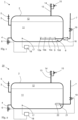
- the device 1 has a container 2 for receiving added water for the production of fresh concrete, which is equipped with a supply line 3 for the supply of fresh added water and with an outlet 4 for discharging cooled added water.
- a valve 5, 6 is provided in each of the inlet line 3 and the outlet line 4 for controlling the flow rate of the respective liquid.
- a feed line 7 for a cryogenic medium opens into a lower region of the container 2 at an inlet device 8 .
- the entry device 8 is in 1 shown embodiment around a hollow body 9, which is equipped with a plurality of outlet openings 10a, 10b, 10c, 10d, through which the cryogenic medium is fed into the feed water.
- the hollow body 9 can be tubular or have some other geometry, for example spherical. However, it can also be a sintered body made of metal, ceramic or plastic, which is gas-permeable and at least largely liquid-tight; in this case the cryogenic medium is supplied as a cold gas.
- the container 2 is filled with additional water up to a level at which the entry device 8 is completely within a liquid bath 11.
- the cryogenic medium is then conducted at a temperature of, for example, between -100° C. and -196° C. via the feed line 7 to the entry device 8 .
- the cryogenic medium emerges from the inlet device 8 at the outlet openings 10a, 10b, 10c, 10d.
- the cryogenic medium heats up and rises in the liquid bath 11 in the form of gas bubbles.
- the added water is greatly cooled.
- the rising gas bubbles lead to a flow in the liquid bath 11, as a result of which fresh water is constantly supplied to the inlet device 8 for cooling and at the same time intensive mixing of the liquid bath 11 takes place.
- the still comparatively warm additional water continuously supplied to the input device 8 reduces the risk of the outlet openings 10a, 10b, 10c, 10d icing up.
- the evaporated nitrogen collects above the liquid bath 11 in a gas phase 12 in an upper area of the container 2 and is discharged via an exhaust pipe 13 .
- the nitrogen can then be released into the environment or put to another use.
- a valve 14 with a safety valve 15 is used to control the amount of gas flowing out.
- a check valve 16 such as a flap
- the non-return valve 16 can also be dispensed with.
- the temperature in the liquid bath 11 is continuously monitored on a temperature gauge 17 which is operatively connected to a control unit 18 . As soon as a predetermined temperature of, for example, between 1° C. and 6° C. has been reached in the feed water, feed water can be removed via the outlet line 4 and fed to its intended use. Fresh water for addition is then fed in via the feed 3 .
- the temperature recorded on the temperature meter 17 can also be used to control the quantity of cryogenic medium supplied, in order to keep the temperature of the liquid bath 11 within a predetermined temperature range, regardless of a withdrawal.
- a valve 19 in the supply line 7, which is operatively connected to the control unit 18, is used for this purpose.
- the device 1 shown is particularly suitable when the pressure of the cryogenic medium fed in via the feed line 7 is entered at a comparatively low overpressure of 0.2 bar to 2 bar compared to the hydrostatic pressure in the liquid bath 11 .
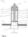
- the 2 Device 20 shown differs from device 1 1 only by another entry device.
- the other parts of the device 20 correspond to those of the device 1 and are therefore identified by the same reference symbols.
- the device 20 has an entry device 21 arranged in a lower area of the container 2, which is connected to a pressure-resistant supply line 7 and is equipped with an entry nozzle 22 arranged essentially horizontally here.
- the entry nozzle 22 is designed as a self-closing nozzle, which falls below a predetermined differential pressure between the pressure of the cryogenic medium in the supply line 7 and the hydrostatic pressure of the added water in the liquid bath 11 goes into a closed state, which lasts until the differential pressure is exceeded again.
- the insertion nozzle 22 comprises a longitudinally movable closing body 24 which is accommodated in a housing 23 and which, when the insertion nozzle 22 is in the closed state (as in 3 shown) seated with a front portion 25 on an annular seat 26 of the housing 23 sealing.
- the housing 23 is mounted in a wall of the container 2, for example by screwing, and has a fastening section 27, for example a screw thread, for detachably connecting the supply line 7.
- the closing body 24 comprises a shank 28 attached to the front portion 25, which extends through the housing 23 and is supported in the radial direction by two centering discs 29, 30, of which the centering disc 29 is fixed to the shank 28 by means of screw 31 and together with the closing body 24 is moved in the housing 23, while the centering disk 30 is fixed to the housing 23, for example by screwing, but allows the axial movement of the shaft 28 through a central bore 32 therethrough.
- the centering disks 29, 30 there are flow openings (not shown here) which allow cryogenic medium to flow through.
- a spring 33 extends between the centering discs 29, 30, radially on the outside of the shaft 28.
- the spring 33 is preferably under pretension when the feed nozzle 22 is in the closed state, so that the front section 25 is pressed against the seat 26, and the added water is thus prevented from penetrating from the liquid bath 11 into the housing 23 or the supply line 7 is reliably avoided.
- a flow body 34 is arranged, which has the shape of a cone tapering into the interior of the container 2 or a bell-shaped body of revolution. If the entry nozzle 22 is in the open position, cryogenic cooling medium flows from the supply line 7 through the annular gap between the seat 26 and the front section 25 in a jet shape into the liquid bath 11 in the container 2, entraining the surrounding added water with it and mixing intimately with it. This creates a flow of uncooled added water in the liquid bath 11 that is directed radially toward the feed nozzle 22 and is deflected by the flow body 34 in the direction of the interior of the container 2 . The comparatively warm added water flowing along the flow body 34 heats the front section 25 as a whole and thus prevents ice from forming in the area of the feed nozzle 22.
Landscapes
- Engineering & Computer Science (AREA)
- General Engineering & Computer Science (AREA)
- Chemical & Material Sciences (AREA)
- Mechanical Engineering (AREA)
- Ceramic Engineering (AREA)
- Dispersion Chemistry (AREA)
- Materials Engineering (AREA)
- Structural Engineering (AREA)
- Organic Chemistry (AREA)
- Filling Or Discharging Of Gas Storage Vessels (AREA)
Abstract
Eine Vorrichtung (1) zum Kühlen von Zugabewasser umfasst einen Behälter (2) zum Aufnehmen eines Flüssigkeitsbades (11), in den eine Zuleitung (7) für ein kryogenes Medium einmündet. Die Zuleitung (7) mündet an einer Eintragseinrichtung (8, 21) in das Flüssigkeitsbad (11) ein. Um zu verhindern, dass während Betriebspausen Zugabewasser aus dem Flüssigkeitsbad (11) in die Zuleitung (7) eindringt, ist die Zuleitung (7) und/oder die Eintragseinrichtung (8, 21) mit Mitteln - z.B mit einer Rückschlagarmatur (16) oder mit einer selbstschließenden Eintragsdüse (22) - zum Verhindern des Rückflusses von Zugabewasser in die Zuleitung (7) ausgerüstet.A device (1) for cooling the added water comprises a container (2) for receiving a liquid bath (11) into which a feed line (7) for a cryogenic medium opens. The feed line (7) opens into the liquid bath (11) at an entry device (8, 21). In order to prevent make-up water from the liquid bath (11) from penetrating into the supply line (7) during breaks in operation, the supply line (7) and/or the input device (8, 21) is equipped with means - e.g. with a non-return valve (16) or with a self-closing feed nozzle (22) - equipped to prevent backflow of make-up water into the feed line (7).
Description
Die Erfindung betrifft eine Vorrichtung zum Kühlen von Zugabewasser für die Herstellung von Frischbeton, mit einem Behälter zum Aufnehmen eines aus Zugabewasser bestehenden Flüssigkeitsbades und mit einer Zuleitung für ein kryogenes Medium, die mit einer in das Flüssigkeitsbad im Behälter einmündenden Eintragseinrichtung strömungsverbunden ist.The invention relates to a device for cooling mixing water for the production of fresh concrete, with a container for receiving a liquid bath consisting of mixing water and with a supply line for a cryogenic medium, which is flow-connected to an inlet device opening into the liquid bath in the container.
Die Temperatur von Frischbeton wird auf Grund von gesetzlichen Empfehlungen, Vorschriften und Richtlinien sowie projektgebundenen Vorgaben in vielen Ländern zunehmend begrenzt, um Temperaturspannungsrisse zu vermeiden, die die Druckfestigkeit des Betons und die Langlebigkeit des Bauwerkes mindern können. Eine Möglichkeit zur Temperaturkontrolle des Frischbetons besteht in der Kühlung des Zugabewassers, das dazu auf einen Wert von beispielsweise knapp über 0°C gebracht wird. Hierzu finden derzeit Kühlsysteme auf elektrischer Basis oder auch unter Verwendung von Flüssigstickstoff Verwendung.The temperature of fresh concrete is increasingly limited due to legal recommendations, regulations and guidelines as well as project-related specifications in many countries in order to avoid temperature stress cracks, which can reduce the compressive strength of the concrete and the longevity of the structure. One way of controlling the temperature of the fresh concrete is to cool the added water, which is brought to a value of just over 0°C, for example. Cooling systems based on electricity or using liquid nitrogen are currently used for this purpose.
Bei der Kühlung mittels eines kryogenen Kühlmediums, wie beispielsweise flüssiger Stickstoff, wird dieser entweder direkt, etwa mittels Lanzen, in die Flüssigkeit eingetragen, oder es erfolgt eine indirekte Kühlung an einer Wärmetauscherfläche eines Wärmetauschers, wobei die zu kühlende Flüssigkeit mittels Pumpen, Rührwerken oder sonstiger Agitatoren in beständige Bewegung gebracht wird, um eine möglichst gleichmäßige Kühlung der Flüssigkeit sicherzustellen und eine Vereisung der Lanze oder der Wärmetauscherfläche zu verhindern.When cooling using a cryogenic cooling medium, such as liquid nitrogen, this is either introduced directly into the liquid, for example by means of lances, or there is indirect cooling on a heat exchanger surface of a heat exchanger, with the liquid to be cooled using pumps, agitators or other Agitators is brought into constant motion in order to ensure that the liquid is cooled as evenly as possible and to prevent the lance or the heat exchanger surface from icing up.
Die
Aus der
Aus der
Nachteilig bei diesen Systemen, in denen verflüssigtes Gas direkt in das Zugabewasser eingespeist wird, ist jedoch, dass es am Eintragspunkt des Gases zu Vereisungen kommt, die die Funktionsfähigkeit des Systems beeinträchtigen können. Zudem kann während einer Betriebspause Zugabewasser in die Zuleitung für das kryogene Medium eindringen und nach der erneuten Inbetriebnahme dort gefrieren, wodurch ebenfalls die Funktionsfähigkeit beeinträchtigt wird.However, the disadvantage of these systems, in which liquefied gas is fed directly into the make-up water, is that icing occurs at the entry point of the gas, which can impair the functionality of the system. In addition, make-up water can penetrate into the supply line for the cryogenic medium during a break in operation and freeze there after the restart, which also impairs the functionality.
In der
Der Erfindung liegt daher die Aufgabe zu Grunde, eine Vorrichtung zum Kühlen von Zugabewasser für die Herstellung von Frischbeton zu schaffen, bei der die Gefahr von Vereisungen gegenüber den Gegenständen nach dem Stande der Technik weiter reduziert ist.The invention is therefore based on the object of creating a device for cooling the added water for the production of fresh concrete, in which the risk of icing is further reduced compared to the objects according to the prior art.
Gelöst ist diese Aufgabe durch eine Vorrichtung mit den Merkmalen des Patentanspruchs 1. Vorteilhafte Ausgestaltungen der Erfindung sind in den Unteransprüchen angegeben.This object is achieved by a device having the features of
Eine erfindungsgemäße Vorrichtung der eingangs genannten Art und Zweckbestimmung ist also dadurch gekennzeichnet, dass die Zuleitung und/oder die Eintragseinrichtung mit Mitteln zum Verhindern einer Rückströmung von Zugabewasser aus dem Flüssigkeitsbad in die Zuleitung ausgerüstet ist.A device according to the invention of the type and purpose mentioned at the outset is thus characterized in that the supply line and/or the entry device is equipped with means for preventing the added water from the liquid bath from flowing back into the supply line.
Erfindungsgemäß wird also das kryogene Medium direkt in das Flüssigkeitsbad des Zugabewassers im Behälter eingespeist. Die Zuführung des kryogenen Mediums kühlt das umgebende Zugabewasser ab und sorgt gleichzeitig für eine Strömung im Flüssigkeitsbad. Die Mittel zum Verhindern der Rückströmung sollen im Falle einer Betriebspause oder eines verminderten Eintrags von kryogenem Medium in das Flüssigkeitsbad eine Vereisung der Eintragseinrichtung oder der Zuleitung vermeiden. Die Wahl der der Mittel zum Verhindern einer Rückströmung des Zugabewassers hängen insbesondere von der Druckdifferenz zwischen dem Druck des kryogenen Mediums in der Zuführung und dem hydrostatischen Druck des Zugabewassers im Behälter ab.According to the invention, the cryogenic medium is fed directly into the liquid bath of the added water in the container. The supply of the cryogenic medium cools the surrounding dosing water and at the same time ensures a flow in the liquid bath. The means for preventing the backflow are intended to prevent the inlet device or the feed line from icing up in the event of a break in operation or a reduced inlet of cryogenic medium into the liquid bath. The choice of the means for preventing backflow of the make-up water depends in particular on the pressure difference between the pressure of the cryogenic medium in the feed and the hydrostatic pressure of the make-up water in the tank.
Die Mittel zum Verhindern einer Rückströmung weisen in einer bevorzugten Ausgestaltung der Erfindung einen in der Zuleitung zur Eintragseinrichtung und/oder in einer der Eintragseinrichtung angeordneten und/oder als Eintragseinrichtung fungierenden Sinterkörper aus einem flüssigkeitsdichten, jedoch gasdurchlässigen Material auf. Der Sinterkörper verhindert das Eindringen von Zugabewasser in die Zuleitung im Falle von Betriebspausen oder einem im Vergleich zum hydrostatischen Druck im Behälter bestehenden Unterdruck in der Zuleitung. Die Eintragseinrichtung kann auch selbst als ein mit der Zuleitung für das kryogene Medium strömungsverbundener Sinterkörper ausgebildet sein, der das Einperlen zumindest von gasförmigem kryogenen Medium, wie beispielweise kaltem gasförmigem Stickstoff, in das Flüssigkeitsbad erlaubt.In a preferred embodiment of the invention, the means for preventing a backflow have a sintered body made of a liquid-tight but gas-permeable material arranged in the supply line to the inlet device and/or in one of the inlet device and/or functioning as inlet device. The sintered body prevents dosing water from penetrating the supply line in the event of a break in operation or if the pressure in the supply line is negative compared to the hydrostatic pressure in the tank. The entry device itself can also be designed as a sintered body which is flow-connected to the supply line for the cryogenic medium and which allows at least gaseous cryogenic medium, such as cold gaseous nitrogen, to bubble into the liquid bath.
Alternativ oder ergänzend dazu kommt in einer anderen vorteilhaften Ausgestaltung als Eintragseinrichtung ein rohrförmiger oder flächiger Hohlkörper zum Einsatz, der mit einer Austrittsöffnung oder einer Mehrzahl von Austrittsöffnungen zur Erzeugung von in der Flüssigkeit aufsteigenden Gasblasen ausgerüstet ist. Dabei verhindert eine separat in der Eintragseinrichtung und/oder der Zuleitung für das kryogene Medium angeordnete Rückschlagarmatur das Eindringen von Zugabewasser. Die Rückschlagarmatur ist bevorzugt so eingestellt, dass sie erst oberhalb eines vorgegebenen Überdrucks in der Zuleitung gegenüber dem hydrostatischen Druck im Behälter öffnet.Alternatively or additionally, in another advantageous embodiment, a tubular or flat hollow body is used as the entry device, which is equipped with an outlet opening or a plurality of outlet openings for generating gas bubbles rising in the liquid. A non-return valve arranged separately in the inlet device and/or in the feed line for the cryogenic medium prevents the make-up water from penetrating. The non-return valve is preferably set in such a way that it only opens above a predetermined excess pressure in the supply line compared to the hydrostatic pressure in the container.
Die vorgenannten Ausgestaltungen mit Sinterkörper oder Hohlkörper eignen sich insbesondere bei einer Betriebsweise mit einer vergleichsweise geringen Druckdifferenz von beispielsweise 0,2 bar bis 2 bar zwischen dem Druck des kryogenen Mediums in der Zuführung und dem hydrostatischen Druck des Zugabewassers im Behälter.The aforementioned configurations with sintered bodies or hollow bodies are particularly suitable for operation with a comparatively low pressure difference of, for example, 0.2 bar to 2 bar between the pressure of the cryogenic medium in the feed and the hydrostatic pressure of the make-up water in the tank.
Insbesondere bei einem im Betrieb der Vorrichtung höheren Druckdifferenz von beispielsweise zwischen 0,5 bar und 10 bar oder darüber zwischen dem Druck in der Zuleitung und dem hydrostatischem Druck im Behälter erweist sich eine Ausgestaltung der Erfindung als besonders vorteilhaft, bei der die Eintragseinrichtung mit einer selbstschließenden Eintragsdüse ausgerüstet ist, die bei Vorliegen eines vorgegebenen minimalen Überdrucks des kryogenen Mediums in der Zuleitung gegenüber dem hydrostatischen Druck des Zugabewassers im Behälter eine Strömungsverbindung für das kryogene Medium aus der Zuleitung in den Behälter öffnet, jedoch bei Unterschreiten des minimalen Überdrucks die Strömungsverbindung zwischen Zuleitung und Behälter schließt. Die Eintragsdüse erzeugt im Flüssigkeitsbad eine starke Strömung und kann im Behälter horizontal oder vertikal angeordnet sein, sodass im Behälter eine horizontale bzw. vertikale Strömung erzeugt wird.In particular, if the pressure difference between the pressure in the supply line and the hydrostatic pressure in the container is higher during operation of the device, for example between 0.5 bar and 10 bar or more, an embodiment of the invention has proven to be particularly advantageous in which the entry device is equipped with a self-closing entry nozzle, which opens a flow connection for the cryogenic medium from the supply line into the container when there is a predetermined minimum overpressure of the cryogenic medium in the supply line compared to the hydrostatic pressure of the added water in the container, but if the minimum overpressure is not reached, the flow connection between the supply line and container closes. The entry nozzle generates a strong flow in the liquid bath and can be arranged horizontally or vertically in the tank so that a horizontal or vertical flow is generated in the tank.
Beispielsweise weist die Eintragsdüse dazu einen in einem Gehäuse aufgenommenen Schließkörper auf, der gegen die Wirkung einer Feder aus einem Schließzustand, in dem er auf einem Sitz des Gehäuses dichtend aufliegt, in einen Öffnungszustand bringbar ist, in der der Schließkörper einen Strömungsweg für das kryogene Medium in den Behälter freigibt. Durch die Feder wird die selbsttätige Rückführung in die Schließposition gewährleistet, wenn der Druck des kryogenen Mediums in der Zuleitung so weit absinkt, dass die auf den Schließkörper wirkende Kraft auf einen Wert unterhalb eines durch die Federspannung definierten Mindestwert absinkt.For example, the insertion nozzle has a closing body accommodated in a housing, which can be brought against the action of a spring from a closed state, in which it rests sealingly on a seat of the housing, into an open state, in which the closing body opens a flow path for the cryogenic medium released into the container. The spring ensures automatic return to the closed position when the pressure of the cryogenic medium in the supply line drops so far that the force acting on the closing body drops to a value below a minimum value defined by the spring tension.
Eine besonders vorteilhafte Ausgestaltung sieht dabei vor, dass der Schließkörper einen im Schließzustand auf einem ringförmigen Sitz des Gehäuses aufliegenden Schließteller aufweist, der in einen unter Freigabe eines Ringspalts in eine vom Sitz beabstandete Position (Öffnungszustand) bewegbar ist. Der ringförmige Sitz ist beispielsweise im Bereich der Stirnseite eines rohrförmig ausgebildeten Gehäuses angeordnet. Aus dem Ringspalt tritt das kryogene Medium als Flüssigkeitsstrahl tief in das Flüssigkeitsbad ein und sorgt so für eine intensive Durchmischung von kryogenem Medium und Zugabewasser.A particularly advantageous embodiment provides that the closing body has a closing plate which rests on an annular seat of the housing in the closed state and which can be moved into a position spaced from the seat (open state) while releasing an annular gap. The annular seat is arranged, for example, in the area of the end face of a tubular housing. The cryogenic medium emerges deep from the annular gap as a jet of liquid into the liquid bath and thus ensures intensive mixing of the cryogenic medium and the added water.
Um der Gefahr einer Vereisung der Eintragsdüse zu begegnen, ist es vorteilhaft, der Eintragsdüse Strömungsmittel zuzuordnen, um durch den Eintritt des kryogenen Mediums in das Flüssigkeitsbad in das Zugabewasser zugleich eine Strömung zu erzeugen, die auf den Schließkörper und/oder auf das Gehäuse der Eintragsdüse gerichtet ist. Durch die Wirkung der Strömungsmittel wird vergleichsweise warmes Zugabewasser mit der Eintragsdüse in Kontakt gebracht, wodurch diese erwärmt und somit die Gefahr einer Vereisung vermindert wird. Die Strömungsmittel können beispielsweise einen um eine Austrittsöffnung der Eintragsdüse herum angeordneten Strömungskörper in Form eines Trichters oder Rohrs umfassen; besitzt, wie im oben genannten Beispiel, die Austrittsöffnung im Öffnungszustand der Eintragsdüse für das kryogene Medium an der Eintragsdüse die Form eines Ringspalts, aus dem das kryogene Medium in das Flüssigkeitsbad einströmt, eignet sich als Strömungskörper insbesondere ein axial vor der Austrittsöffnung angeordneter, zum Behälterinnern sich verjüngender Kegel oder glockenförmiger Rotationskörper. Dieser begünstigt die Ausbildung eines tief in das Behälterinnere hineinreichenden Strahls aus ausströmendem kryogenen Medium und mitgerissenem Zugabewasser mit der Folge, dass dem Schließkörper bzw. dem Gehäuse der Eintragsdüse beständig warmes Zugabewasser aus der Umgebung zugeführt wird.In order to counteract the risk of the entry nozzle icing up, it is advantageous to allocate flow means to the entry nozzle in order to simultaneously generate a flow through the entry of the cryogenic medium into the liquid bath in the added water, which flows onto the closing body and/or onto the housing of the entry nozzle is directed. Due to the effect of the flow means, comparatively warm feed water is brought into contact with the feed nozzle, as a result of which it is heated and the risk of icing is reduced. The flow means can comprise, for example, a flow body in the form of a funnel or tube arranged around an outlet opening of the entry nozzle; If, as in the above example, the outlet opening in the open state of the inlet nozzle for the cryogenic medium on the inlet nozzle has the shape of an annular gap, from which the cryogenic medium flows into the liquid bath, a particularly suitable flow body is one arranged axially in front of the outlet opening, towards the interior of the container tapered cone or bell-shaped body of revolution. This promotes the formation of a jet of outflowing cryogenic medium and entrained added water that reaches deep into the interior of the container, with the result that the closing body or the housing of the feed nozzle is constantly supplied with warm added water from the environment.
Als Behälter kann ein offener Behälter vorgesehen sein, beispielsweise ein Becken oder ein Teich. Die Ausgestaltung des Behälters als geschlossener, mit einem an eine Gasableitung angeschlossenen Behälter ist jedoch bevorzugt, da in diesem Fall der austretende Gasfluss kontrolliert abgeführt werden kann.An open container can be provided as the container, for example a basin or a pond. However, the design of the container as a closed container connected to a gas discharge line is preferred, since in this case the escaping gas flow can be discharged in a controlled manner.
In einer abermals bevorzugten Ausgestaltung der Erfindung ist in der Zuleitung ein mit dem Flüssigkeitsbad in thermischen kontakt stehender Wärmetauscher integriert. Beim Durchlaufen des Wärmetauschers erwärmt sich und/oder verdampft das kryogene Medium wodurch die Gefahr einer Vereisung weiter reduziert wird, gleichzeitig kühlt der Wärmetauscher das Flüssigkeitsbad.In another preferred embodiment of the invention, a heat exchanger that is in thermal contact with the liquid bath is integrated in the supply line. As it passes through the heat exchanger, the cryogenic medium heats up and/or evaporates, which further reduces the risk of icing, while the heat exchanger cools the liquid bath at the same time.
Bevorzugt ist der Behälter mit Mitteln zum Regeln der Temperatur des dem Behälter entnehmbaren Zugabewassers ausgerüstet. Dabei handelt es sich beispielsweise um einen Temperaturmesser, der mit einem in einer Entnahmeleitung angeordneten Entnahmeventil in Wirkverbindung steht. Der Temperaturmesser misst kontinuierlich die Temperatur eines im Behälter vorliegenden Bades aus Zugabewasser. Bei Erreichen einer vorgegebenen Temperatur im Bad von beispielsweise zwischen 1°C und 5°C wird eine kontrollierte Abgabe von Zugabewasser über die Entnahmeleitung ermöglicht; gleichzeitig oder anschließend wird dem Behälter über eine Zuführleitung frisches Wasser zwecks Kühlung zugeführt. Im Übrigen kann die Temperatur des Zugabewassers im Behälter über eine Regelung der Menge des eingetragenen kryogenen Kühlmediums mittels eines mit einem Temperaturmesser im Behälter in Wirkverbindung stehenden, in der Zuleitung für das kryogene Medium angeordneten Ventils gesteuert werden.The container is preferably equipped with means for regulating the temperature of the make-up water which can be drawn from the container. This is, for example, a temperature gauge that is in operative connection with a removal valve arranged in a removal line. The temperature meter continuously measures the temperature of a bath of make-up water present in the tank. When a predetermined temperature is reached in the bath, for example between 1° C. and 5° C., it is possible to dispense additional water in a controlled manner via the extraction line; at the same time or subsequently, fresh water is supplied to the container via a supply line for the purpose of cooling. In addition, the temperature of the water to be added in the container can be controlled by regulating the amount of cryogenic cooling medium introduced by means of a valve arranged in the supply line for the cryogenic medium and which is operatively connected to a temperature meter in the container.
Beim kryogenen Kühlmedium handelt es sich bevorzugt um flüssigen oder kalten gasförmigen Stickstoff.The cryogenic cooling medium is preferably liquid or cold gaseous nitrogen.
Anhand der Zeichnungen sollen Ausführungsbeispiele der Erfindung näher erläutert werden. In schematischen Ansichten zeigen:
-
Fig. 1 : Eine erfindungsgemäße Vorrichtung in einer ersten Ausführungsform, -
Fig. 2 : Eine erfindungsgemäße Vorrichtung in einer zweiten Ausführungsform -
Fig. 3 : Die Eintragseinrichtung der Vorrichtung ausFig. 2 im Längsschnitt.
-
1 : A device according to the invention in a first embodiment, -
2 : A device according to the invention in a second embodiment -
3 : The entry facility of the device off2 in longitudinal section.
Die in
In einen unteren Bereich des Behälters 2 mündet eine Zuleitung 7 für ein kryogenes Medium, beispielsweise flüssiger oder tiefkalter gasförmiger Stickstoff, an einer Eintragseinrichtung 8 ein.A
Bei der Eintragseinrichtung 8 handelt es sich in dem in
Im Betrieb der Vorrichtung 1 wird der Behälter 2 mit Zugabewasser bis zu einer Höhe gefüllt, bei der die Eintragseinrichtung 8 vollständig innerhalb eines Flüssigkeitsbades 11 vorliegt. Sodann wird das kryogene Medium mit einer Temperatur von beispielsweise zwischen -100°C und -196°C, über die Zuleitung 7 zur Eintragseinrichtung 8 geleitet. Das kryogene Medium tritt an den Austrittsöffnungen 10a, 10b, 10c, 10d aus der Eintragseinrichtung 8 aus. Beim Kontakt mit dem Zugabewasser erwärmt sich das kryogene Medium und steigt in Form von Gasblasen im Flüssigkeitsbad 11 auf. Gleichzeitig wird das Zugabewasser stark abgekühlt. Die aufsteigenden Gasblasen führen zu einer Strömung im Flüssigkeitsbad 11, aufgrund der der Eintragseinrichtung 8 beständig frisches Zugabewasser zur Kühlung zugeführt wird und zugleich eine intensive Durchmischung des Flüssigkeitsbades 11 erfolgt. Das der Eintragseinrichtung 8 laufend zugeführte, noch vergleichsweise warme Zugabewasser reduziert die Gefahr einer Vereisung der Austrittsöffnungen 10a, 10b, 10c, 10d.During operation of the
Der verdampfte Stickstoff sammelt sich oberhalb des Flüssigkeitsbades 11 in einer Gasphase 12 in einem oberen Bereich des Behälters 2 an und wird über eine Abgasleitung 13 abgeführt. Der Stickstoff kann anschließend in die Umgebung entlassen oder einer sonstigen Verwendung zugeführt werden. Zur Kontrolle der abströmenden Gasmenge dient ein Ventil 14 mit Sicherheitsventil 15.The evaporated nitrogen collects above the
Um zu verhindern, dass, etwa während einer Betriebsruhe, eingedrungenes Zugabewasser nach der Wiederinbetriebnahme der Vorrichtung 1 zu unerwünschten Eisbildungen in der Zuleitung 7 führt, ist in der Zuleitung 7, stromauf zur Eintragseinrichtung 8, eine Rückschlagarmatur 16, beispielsweise eine Klappe, vorgesehen. Bei Wahl eines gasdurchlässigen, jedoch flüssigkeitsdichten Sinterkörpers als Eintragseinrichtung 8 kann auf die Rückschlagarmatur 16 jedoch auch verzichtet werden.In order to prevent that, for example during a shutdown, penetrating added water after restarting the
Die Temperatur im Flüssigkeitsbad 11 wird an einem Temperaturmesser 17, der mit einer Steuereinheit 18 wirkverbunden ist, laufend kontrolliert. Sobald eine vorgegebene Temperatur im Zugabewasser von beispielsweise zwischen 1°C und 6°C erreicht ist, kann Zugabewasser über die Ausleitung 4 entnommen und seiner beabsichtigten Verwendung zugeführt werden. Anschließend wird frisches Zugabewasser über die Zuführung 3 eingespeist. Die am Temperaturmesser 17 erfasste Temperatur kann auch dazu genutzt werden, die Menge an zugeführtem kryogenen Medium zu steuern, um die Temperatur des Flüssigkeitsbades 11 unabhängig von einer Entnahme in einem vorgegebenen Temperaturbereich zu halten. Hierzu dient ein mit der Steuereinheit 18 wirkverbundenes Ventil 19 in der Zuleitung 7.The temperature in the
Die in
Die in
Die Vorrichtung 20 weist eine in einem unteren Bereich des Behälters 2 angeordnete Eintragseinrichtung 21 auf, die an einer druckfesten Zuleitung 7 angeschlossen ist und mit einer hier im Wesentlichen horizontal angeordneten Eintragsdüse 22 ausgerüstet ist.The
Die Eintragsdüse 22 ist als selbstschließende Düse ausgebildet, die bei Unterschreiten eines vorgegebenen Differenzdrucks zwischen dem Druck des kryogenen Mediums in der Zuleitung 7 und dem hydrostatischen Druck des Zugabewassers im Flüssigkeitsbad 11 in einen Schließzustand übergeht, der so lange anhält, bis der Differenzdruck erneut überschritten wird.The
In
Bei Vorhandensein eines gewissen, die Vorspannung der Feder 33 überwindenden minimalen Überdrucks von beispielsweise 0,5 bar oder mehr in der Zuleitung 7 gegenüber dem hydrostatischen Druck des Flüssigkeitsbades 11 im Behälter 2 bewegt sich der Schließkörper 24 gegen die Kraft der Feder 33 in Richtung auf das Innere des Behälters 2. Dabei öffnet sich zwischen Sitz 26 und Vorderabschnitt 25 ein Ringspalt, der das Einströmen von kryogenem Medium aus der Zuleitung 7 in das Flüssigkeitsbad 11 ermöglicht. Die Eintragsdüse 22 befindet sich somit in Öffnungsposition. Reduziert sich dagegen der Druck in der Zuleitung 7 unter den minimalen Überdruck, gelangt die Eintragsdüse 22 unter der Wirkung der Feder 33 selbsttätig zurück in ihre Schließposition.If there is a certain minimum excess pressure of, for example, 0.5 bar or more in the
Auf dem Vorderabschnitt 25 ist, auf dessen dem Schaft 28 gegenüberliegenden Seite, ein Strömungskörper 34 angeordnet, der die Gestalt eines sich in das Innere des Behälters 2 verjüngenden Kegels oder glockenförmigen Rotationskörpers besitzt. Befindet sich die Eintragsdüse 22 in Öffnungsposition, strömt kryogenes Kühlmedium aus der Zuleitung 7 durch den Ringspalt zwischen Sitz 26 und Vorderabschnitt 25 strahlförmig in das Flüssigkeitsbad 11 im Behälter 2 ein, reißt dabei umgebendes Zugabewasser mit sich und vermischt sich innig mit diesem. Dadurch entsteht im Flüssigkeitsbad 11 eine radial auf die Eintragsdüse 22 zu gerichtete Strömung aus ungekühltem Zugabewasser, die durch den Strömungskörper 34 in Richtung des Innern des Behälters 2 abgelenkt wird. Das dabei am Strömungskörper 34 entlang strömende, vergleichsweise warme Zugabewasser erwärmt den Vorderabschnitt 25 insgesamt und verhindert dadurch eine Eisbildung im Bereich der Eintragsdüse 22.On the
Bei den Vorrichtungen 1, 20 wird ein Rückfluss von Zugabewasser aus dem Flüssigkeitsbad 11 in die Zuleitung 7 wirkungsvoll verhindert. Es kommt damit nicht zur Bildung von Wassereis innerhalb der Zuleitung 7 oder in der Eintragseinrichtung 8, 21, die die Funktionsfähigkeit der Vorrichtung 1, 20 beeinträchtigen könnte.
Claims (10)
dadurch gekennzeichnet,
dass die Zuleitung für das kryogene Medium und/oder die Eintragseinrichtung (8, 21) mit Mitteln (16, 4) zum Verhindern einer Rückströmung von Zugabewasser aus dem Flüssigkeitsbad (11) in die Zuleitung (7) ausgerüstet ist.Device for cooling mixing water for the production of fresh concrete, with a container (2) for receiving a liquid bath (11) consisting of mixing water and with a supply line (7) for a cryogenic medium, which is connected to a liquid bath (11) in the container (2) flow-connected to the entry device (8, 21),
characterized,
that the supply line for the cryogenic medium and/or the entry device (8, 21) is equipped with means (16, 4) for preventing added water from the liquid bath (11) from flowing back into the supply line (7).
Applications Claiming Priority (1)
| Application Number | Priority Date | Filing Date | Title |
|---|---|---|---|
| DE102021005359.1A DE102021005359A1 (en) | 2021-10-28 | 2021-10-28 | Device for cooling the mixing water for the production of fresh concrete |
Publications (1)
| Publication Number | Publication Date |
|---|---|
| EP4173788A1 true EP4173788A1 (en) | 2023-05-03 |
Family
ID=84044203
Family Applications (1)
| Application Number | Title | Priority Date | Filing Date |
|---|---|---|---|
| EP22200343.6A Pending EP4173788A1 (en) | 2021-10-28 | 2022-10-07 | Device for cooling feed water for the production of fresh concrete |
Country Status (2)
| Country | Link |
|---|---|
| EP (1) | EP4173788A1 (en) |
| DE (1) | DE102021005359A1 (en) |
Citations (7)
| Publication number | Priority date | Publication date | Assignee | Title |
|---|---|---|---|---|
| DE3828136A1 (en) | 1988-08-18 | 1990-02-22 | Linde Ag | METHOD AND DEVICE FOR COOLING A CONTAINER FILLED WITH LIQUID |
| DE102006027561A1 (en) * | 2006-06-14 | 2007-12-20 | Messer France S.A.S | Device for metering in a cryogenic medium |
| EP2179782A1 (en) * | 2008-10-22 | 2010-04-28 | Messer France S.A.S. | Assembly for introducing liquid carbon dioxide into a medium |
| EP2309160A1 (en) * | 2009-10-06 | 2011-04-13 | Messer France S.A.S. | Device for metering a cryogenic medium |
| WO2012010705A1 (en) | 2010-07-23 | 2012-01-26 | Air Liquide Deutschland Gmbh | Method and device for cooling a liquid |
| EP2142862B1 (en) | 2007-04-04 | 2019-07-17 | L'Air Liquide Société Anonyme pour l'Etude et l'Exploitation des Procédés Georges Claude | Method and use of a device for cooling process water used in the production of freshly mixed concrete |
| WO2021121652A1 (en) * | 2019-12-18 | 2021-06-24 | Linde Gmbh | Method and arrangement for introducing gas into a medium |
Family Cites Families (1)
| Publication number | Priority date | Publication date | Assignee | Title |
|---|---|---|---|---|
| DE102009029893B4 (en) | 2009-06-23 | 2014-05-22 | Messer Group Gmbh | Apparatus and method for cooling and introducing a trickle or powdery material flow in a storage container |
-
2021
- 2021-10-28 DE DE102021005359.1A patent/DE102021005359A1/en active Pending
-
2022
- 2022-10-07 EP EP22200343.6A patent/EP4173788A1/en active Pending
Patent Citations (7)
| Publication number | Priority date | Publication date | Assignee | Title |
|---|---|---|---|---|
| DE3828136A1 (en) | 1988-08-18 | 1990-02-22 | Linde Ag | METHOD AND DEVICE FOR COOLING A CONTAINER FILLED WITH LIQUID |
| DE102006027561A1 (en) * | 2006-06-14 | 2007-12-20 | Messer France S.A.S | Device for metering in a cryogenic medium |
| EP2142862B1 (en) | 2007-04-04 | 2019-07-17 | L'Air Liquide Société Anonyme pour l'Etude et l'Exploitation des Procédés Georges Claude | Method and use of a device for cooling process water used in the production of freshly mixed concrete |
| EP2179782A1 (en) * | 2008-10-22 | 2010-04-28 | Messer France S.A.S. | Assembly for introducing liquid carbon dioxide into a medium |
| EP2309160A1 (en) * | 2009-10-06 | 2011-04-13 | Messer France S.A.S. | Device for metering a cryogenic medium |
| WO2012010705A1 (en) | 2010-07-23 | 2012-01-26 | Air Liquide Deutschland Gmbh | Method and device for cooling a liquid |
| WO2021121652A1 (en) * | 2019-12-18 | 2021-06-24 | Linde Gmbh | Method and arrangement for introducing gas into a medium |
Also Published As
| Publication number | Publication date |
|---|---|
| DE102021005359A1 (en) | 2023-05-04 |
Similar Documents
| Publication | Publication Date | Title |
|---|---|---|
| EP3265199B1 (en) | Device for degassing a liquid | |
| DE3419855C3 (en) | Device for delivering a continuous stream of a cryogenic liquid | |
| DE112016000931T5 (en) | Spray nozzle and deaerator | |
| EP1117964B1 (en) | Steam generator with at least partly double-walled evaporation tank | |
| EP4173788A1 (en) | Device for cooling feed water for the production of fresh concrete | |
| WO1997046839A2 (en) | Expansion nozzle and process for making carbon dioxide snow | |
| AT9291U1 (en) | STORAGE CONTAINER FOR LOW-COLD LIQUEFIED GAS USING A REMOVAL DEVICE | |
| DE102021005341B4 (en) | Device for cooling liquids | |
| EP2179782A1 (en) | Assembly for introducing liquid carbon dioxide into a medium | |
| DE2159963A1 (en) | Ball container and device for controlling cavitation in liquids | |
| WO2008098758A1 (en) | Geothermal probe and method for operating a geothermal probe | |
| EP3623032B1 (en) | Filter system with direct cleaning air injection and method for cleaning | |
| WO2021239977A1 (en) | Tank system for cooling a liquid using thermal stratification | |
| WO1997014922A1 (en) | Process and device for degassing a liquid in a substantially closed system | |
| EP2116330B1 (en) | Block station for blocking spectacle glass blanks on a block piece | |
| EP2467540A1 (en) | Gravity-fed basin | |
| DE202004010834U1 (en) | Controlled temperature treatment vessel comprises cylindrical work chamber ringed by annular chamber fitted with tube to heat or cool incoming compressed air and direct air into main chamber in selected direction. | |
| DE4315864C2 (en) | Heat exchange arrangement | |
| EP1102012B1 (en) | De-gasing installation | |
| EP2129975B1 (en) | Thermal power plant | |
| DE202007018264U1 (en) | geothermal probe | |
| DE2205507C3 (en) | Method and apparatus for producing fibers | |
| DE102008030909B3 (en) | Sliding bearing protection container for compressor stages in water-injection-cooled screw compressor, has container housing, whose longitudinal axis is inclined with inclination angle | |
| AT10810U1 (en) | DEVICE FOR IMPROVING SNOW PRODUCERS | |
| EP2069065B1 (en) | Valve for feeding solutions into crystallizing plants |
Legal Events
| Date | Code | Title | Description |
|---|---|---|---|
| PUAI | Public reference made under article 153(3) epc to a published international application that has entered the european phase |
Free format text: ORIGINAL CODE: 0009012 |
|
| STAA | Information on the status of an ep patent application or granted ep patent |
Free format text: STATUS: THE APPLICATION HAS BEEN PUBLISHED |
|
| AK | Designated contracting states |
Kind code of ref document: A1 Designated state(s): AL AT BE BG CH CY CZ DE DK EE ES FI FR GB GR HR HU IE IS IT LI LT LU LV MC ME MK MT NL NO PL PT RO RS SE SI SK SM TR |
|
| STAA | Information on the status of an ep patent application or granted ep patent |
Free format text: STATUS: REQUEST FOR EXAMINATION WAS MADE |
|
| 17P | Request for examination filed |
Effective date: 20231103 |
|
| RBV | Designated contracting states (corrected) |
Designated state(s): AL AT BE BG CH CY CZ DE DK EE ES FI FR GB GR HR HU IE IS IT LI LT LU LV MC ME MK MT NL NO PL PT RO RS SE SI SK SM TR |