EP4173771B1 - Roboter-master-steuerungssystem - Google Patents
Roboter-master-steuerungssystem Download PDFInfo
- Publication number
- EP4173771B1 EP4173771B1 EP22172420.6A EP22172420A EP4173771B1 EP 4173771 B1 EP4173771 B1 EP 4173771B1 EP 22172420 A EP22172420 A EP 22172420A EP 4173771 B1 EP4173771 B1 EP 4173771B1
- Authority
- EP
- European Patent Office
- Prior art keywords
- robot
- sequence
- objects
- region
- instruction
- Prior art date
- Legal status (The legal status is an assumption and is not a legal conclusion. Google has not performed a legal analysis and makes no representation as to the accuracy of the status listed.)
- Active
Links
Images

Classifications
-
- B—PERFORMING OPERATIONS; TRANSPORTING
- B25—HAND TOOLS; PORTABLE POWER-DRIVEN TOOLS; MANIPULATORS
- B25J—MANIPULATORS; CHAMBERS PROVIDED WITH MANIPULATION DEVICES
- B25J13/00—Controls for manipulators
-
- B—PERFORMING OPERATIONS; TRANSPORTING
- B25—HAND TOOLS; PORTABLE POWER-DRIVEN TOOLS; MANIPULATORS
- B25J—MANIPULATORS; CHAMBERS PROVIDED WITH MANIPULATION DEVICES
- B25J13/00—Controls for manipulators
- B25J13/08—Controls for manipulators by means of sensing devices, e.g. viewing or touching devices
-
- B—PERFORMING OPERATIONS; TRANSPORTING
- B25—HAND TOOLS; PORTABLE POWER-DRIVEN TOOLS; MANIPULATORS
- B25J—MANIPULATORS; CHAMBERS PROVIDED WITH MANIPULATION DEVICES
- B25J9/00—Program-controlled manipulators
- B25J9/0096—Program-controlled manipulators co-operating with a working support, e.g. work-table
-
- B—PERFORMING OPERATIONS; TRANSPORTING
- B25—HAND TOOLS; PORTABLE POWER-DRIVEN TOOLS; MANIPULATORS
- B25J—MANIPULATORS; CHAMBERS PROVIDED WITH MANIPULATION DEVICES
- B25J9/00—Program-controlled manipulators
- B25J9/16—Program controls
- B25J9/1602—Program controls characterised by the control system, structure, architecture
-
- B—PERFORMING OPERATIONS; TRANSPORTING
- B25—HAND TOOLS; PORTABLE POWER-DRIVEN TOOLS; MANIPULATORS
- B25J—MANIPULATORS; CHAMBERS PROVIDED WITH MANIPULATION DEVICES
- B25J9/00—Program-controlled manipulators
- B25J9/16—Program controls
- B25J9/1602—Program controls characterised by the control system, structure, architecture
- B25J9/161—Hardware, e.g. neural networks, fuzzy logic, interfaces, processor
-
- B—PERFORMING OPERATIONS; TRANSPORTING
- B25—HAND TOOLS; PORTABLE POWER-DRIVEN TOOLS; MANIPULATORS
- B25J—MANIPULATORS; CHAMBERS PROVIDED WITH MANIPULATION DEVICES
- B25J9/00—Program-controlled manipulators
- B25J9/16—Program controls
- B25J9/1679—Program controls characterised by the tasks executed
- B25J9/1682—Dual arm manipulator; Coordination of several manipulators
-
- B—PERFORMING OPERATIONS; TRANSPORTING
- B25—HAND TOOLS; PORTABLE POWER-DRIVEN TOOLS; MANIPULATORS
- B25J—MANIPULATORS; CHAMBERS PROVIDED WITH MANIPULATION DEVICES
- B25J9/00—Program-controlled manipulators
- B25J9/16—Program controls
- B25J9/1694—Program controls characterised by use of sensors other than normal servo-feedback from position, speed or acceleration sensors, perception control, multi-sensor controlled systems, sensor fusion
- B25J9/1697—Vision controlled systems
-
- G—PHYSICS
- G05—CONTROLLING; REGULATING
- G05B—CONTROL OR REGULATING SYSTEMS IN GENERAL; FUNCTIONAL ELEMENTS OF SUCH SYSTEMS; MONITORING OR TESTING ARRANGEMENTS FOR SUCH SYSTEMS OR ELEMENTS
- G05B19/00—Program-control systems
- G05B19/02—Program-control systems electric
- G05B19/18—Numerical control [NC], i.e. automatically operating machines, in particular machine tools, e.g. in a manufacturing environment, so as to execute positioning, movement or co-ordinated operations by means of program data in numerical form
- G05B19/4155—Numerical control [NC], i.e. automatically operating machines, in particular machine tools, e.g. in a manufacturing environment, so as to execute positioning, movement or co-ordinated operations by means of program data in numerical form characterised by program execution, i.e. part program or machine function execution, e.g. selection of a program
-
- G—PHYSICS
- G06—COMPUTING OR CALCULATING; COUNTING
- G06N—COMPUTING ARRANGEMENTS BASED ON SPECIFIC COMPUTATIONAL MODELS
- G06N3/00—Computing arrangements based on biological models
- G06N3/004—Artificial life, i.e. computing arrangements simulating life
- G06N3/008—Artificial life, i.e. computing arrangements simulating life based on physical entities controlled by simulated intelligence so as to replicate intelligent life forms, e.g. based on robots replicating pets or humans in their appearance or behaviour
-
- G—PHYSICS
- G06—COMPUTING OR CALCULATING; COUNTING
- G06N—COMPUTING ARRANGEMENTS BASED ON SPECIFIC COMPUTATIONAL MODELS
- G06N3/00—Computing arrangements based on biological models
- G06N3/02—Neural networks
- G06N3/04—Architecture, e.g. interconnection topology
- G06N3/045—Combinations of networks
-
- G—PHYSICS
- G06—COMPUTING OR CALCULATING; COUNTING
- G06N—COMPUTING ARRANGEMENTS BASED ON SPECIFIC COMPUTATIONAL MODELS
- G06N3/00—Computing arrangements based on biological models
- G06N3/02—Neural networks
- G06N3/04—Architecture, e.g. interconnection topology
- G06N3/0464—Convolutional networks [CNN, ConvNet]
-
- G—PHYSICS
- G06—COMPUTING OR CALCULATING; COUNTING
- G06N—COMPUTING ARRANGEMENTS BASED ON SPECIFIC COMPUTATIONAL MODELS
- G06N3/00—Computing arrangements based on biological models
- G06N3/02—Neural networks
- G06N3/08—Learning methods
-
- G—PHYSICS
- G06—COMPUTING OR CALCULATING; COUNTING
- G06N—COMPUTING ARRANGEMENTS BASED ON SPECIFIC COMPUTATIONAL MODELS
- G06N3/00—Computing arrangements based on biological models
- G06N3/02—Neural networks
- G06N3/08—Learning methods
- G06N3/09—Supervised learning
-
- G—PHYSICS
- G06—COMPUTING OR CALCULATING; COUNTING
- G06V—IMAGE OR VIDEO RECOGNITION OR UNDERSTANDING
- G06V10/00—Arrangements for image or video recognition or understanding
- G06V10/70—Arrangements for image or video recognition or understanding using pattern recognition or machine learning
- G06V10/82—Arrangements for image or video recognition or understanding using pattern recognition or machine learning using neural networks
-
- G—PHYSICS
- G06—COMPUTING OR CALCULATING; COUNTING
- G06V—IMAGE OR VIDEO RECOGNITION OR UNDERSTANDING
- G06V20/00—Scenes; Scene-specific elements
- G06V20/60—Type of objects
- G06V20/64—Three-dimensional [3D] objects
-
- G—PHYSICS
- G05—CONTROLLING; REGULATING
- G05B—CONTROL OR REGULATING SYSTEMS IN GENERAL; FUNCTIONAL ELEMENTS OF SUCH SYSTEMS; MONITORING OR TESTING ARRANGEMENTS FOR SUCH SYSTEMS OR ELEMENTS
- G05B2219/00—Program-control systems
- G05B2219/30—Nc systems
- G05B2219/31—From computer integrated manufacturing till monitoring
- G05B2219/31076—Controller for cell, for robot motion, for supervision
-
- G—PHYSICS
- G05—CONTROLLING; REGULATING
- G05B—CONTROL OR REGULATING SYSTEMS IN GENERAL; FUNCTIONAL ELEMENTS OF SUCH SYSTEMS; MONITORING OR TESTING ARRANGEMENTS FOR SUCH SYSTEMS OR ELEMENTS
- G05B2219/00—Program-control systems
- G05B2219/30—Nc systems
- G05B2219/40—Robotics, robotics mapping to robotics vision
- G05B2219/40007—Optimize sequence of pick and place operations upon arrival of workpiece on conveyor
-
- G—PHYSICS
- G05—CONTROLLING; REGULATING
- G05B—CONTROL OR REGULATING SYSTEMS IN GENERAL; FUNCTIONAL ELEMENTS OF SUCH SYSTEMS; MONITORING OR TESTING ARRANGEMENTS FOR SUCH SYSTEMS OR ELEMENTS
- G05B2219/00—Program-control systems
- G05B2219/30—Nc systems
- G05B2219/40—Robotics, robotics mapping to robotics vision
- G05B2219/40532—Ann for vision processing
-
- G—PHYSICS
- G05—CONTROLLING; REGULATING
- G05B—CONTROL OR REGULATING SYSTEMS IN GENERAL; FUNCTIONAL ELEMENTS OF SUCH SYSTEMS; MONITORING OR TESTING ARRANGEMENTS FOR SUCH SYSTEMS OR ELEMENTS
- G05B2219/00—Program-control systems
- G05B2219/30—Nc systems
- G05B2219/45—Nc applications
- G05B2219/45063—Pick and place manipulator
-
- G—PHYSICS
- G05—CONTROLLING; REGULATING
- G05B—CONTROL OR REGULATING SYSTEMS IN GENERAL; FUNCTIONAL ELEMENTS OF SUCH SYSTEMS; MONITORING OR TESTING ARRANGEMENTS FOR SUCH SYSTEMS OR ELEMENTS
- G05B2219/00—Program-control systems
- G05B2219/30—Nc systems
- G05B2219/50—Machine tool, machine tool null till machine tool work handling
- G05B2219/50391—Robot
Definitions
- the present invention relates to the field of machinery, and in particular, to a robot master control system.
- Robots are intelligent machines that may operate semi-autonomously or fully autonomously, have basic functions such as sensing, decision-making, and executing tasks, and may assist or even replace humans in completing dangerous, laborious, and complex tasks.
- robots may be widely used in various fields.
- the operation efficiency of a single robot is low, and how to coordinate multiple robots to operate to improve the operation efficiency has become a new topic that needs to be addressed.
- the present invention provides a robot master control system.
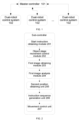
- FIG. 1 is a schematic diagram of a robot master control system according to some exemplary embodiments of the present invention
- a and/or B may represent the following three cases: Only A exists, both A and B exist, and only B exists.
- at least one used herein means any one or any combination of at least two of a plurality, for example, including at least one of A, B, and C may mean including any one or more elements selected from a set formed by A, B and C.
- the exemplary embodiments of the present invention provide a robot master control system.
- the robot master control system may include: A master controller 101, configured to control at least one robot control system.
- a person skilled in the art may understand that the at least one robot control system may control at least one robot.
- the at least one robot control system may be a dual-robot control system 102.
- the master controller may control each dual-robot control system 102 independently.
- Each dual-robot control system 102 may include a first robot, a second robot, a loading table, an image capturing device (e.g., a camera), and a sub-controller.
- the first robot, the second robot, the loading table, and the image capturing device may all be controlled by the sub-controller.
- Each sub-controller is controlled by the master controller.
- the image capturing device is configured to: take photos of the objects on top of the loading table from above, that is, obtain a first image, and transmit the captured first image to the sub-controller.
- the sub-controller may be configured to control the first robot and the second robot according to the photos.
- the first and/or second robot in the present invention may be a robot capable of carrying objects.
- the robot may include a manipulator or a suction cup and may grab or suck an object and carry the object to a designated end point position.
- the sub-controller may include:
- a first image obtaining module 203 may be configured to trigger the image capturing device to perform shooting to obtain the first image captured by the image capturing device.
- a first image analysis module 204 may be configured to analyze the first image to obtain a distribution of the objects on top of the loading table.
- a second position obtaining unit 205 may be configured to obtain a second position, where the second position may be an end point position to which the first robot and/or the second robot conveys an object.
- the second position in some exemplary embodiments may also be set by the master controller.
- An instruction sequence generation unit 206 may be configured to generate, according to the distribution of the objects in the first image and the second position, a first instruction sequence used for controlling the first robot and a second instruction sequence used for controlling the second robot.
- a movement control unit 207 may be configured to respectively control the first robot and the second robot based on the first instruction sequence and the second instruction sequence.
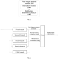
- the first image analysis module 204 may include:
- the neural network includes: a hierarchical convolutional network, an attention-based coding network, a fusion network, and a recognition network.
- the neural network may be trained by using the following method:
- a hierarchical convolutional network may be designed to extract adequately recognizable information layer by layer, thereby increasing the enrichment of information in the extracted first feature information.
- the hierarchical convolutional network in some exemplary embodiments of the present invention may include at least two extraction branches. Certainly, the quantity of extraction branches is not limited in the present invention. However, a larger quantity of extraction branches may indicate a lower speed, and accordingly a better extraction effect.
- a first branch performs a feature extraction operation on an inputted image, to obtain a first feature extraction result.
- the first feature extraction result may be inputted into a second branch after a feature filtering operation, and a second feature extraction result may be obtained after a feature extraction operation of the second branch.
- the first feature extraction result and the second feature extraction result may be fused, so that hidden information may be mined to obtain a more thorough extraction result.
- FIG. 4 is a schematic diagram of a hierarchical convolutional network.
- three extraction branches may be used.
- the hierarchical convolutional network may include a first branch, a second branch, and a third branch.
- the first branch, the second branch, and the third branch may all be configured to perform a feature extraction operation.
- a specific feature extraction operation is not limited in the present invention.
- the feature extraction operation may be a convolution operation or a multi-scale convolution operation.
- the hierarchical convolutional network may further include a fourth branch and a fifth branch.
- the fourth branch and the fifth branch may be respectively connected to the first branch and the second branch and may be both configured to perform a feature filtering operation.
- the feature filtering operation may include an importance degree determining operation and a feature erasing operation based on the importance degree.
- the first feature extraction result outputted by the first branch may be inputted into the fourth branch.
- Region division may be performed in the fourth branch to obtain, for example, at least nine regions.
- Importance degree determining may be performed on information in the first feature extraction result and corresponds to each region, to obtain a first importance degree corresponding to each of the nine regions.
- Information corresponding to a region with a first importance degree greater than a preset threshold may be erased from the first feature extraction result to obtain a first correction information.
- the first correction information may be outputted by the fourth branch and used as an input of the second branch.
- the information corresponding to a relatively important region has already been expressed in the first feature extraction result.
- the fourth branch may record information corresponding to a less important region in the first correction information, and input the first correction information into a next branch (the second branch) to continue to perform feature extraction and obtain the second feature extraction result, so that the hidden information may be mined, and information that is difficult to be extracted in the existing technologies may be extracted by the next branch. Based on such a conception, information that is difficult to be extracted may be mined layer by layer.
- the second branch may obtain the second feature extraction result through a feature extraction operation.
- the second feature extraction result may be then inputted into the fifth branch to perform a feature filtering operation (similar to the feature filtering operation performed by the fourth branch) to obtain a second correction information.
- the second correction information may be inputted into the third branch to obtain a third feature extraction result by a feature extraction operation.
- first feature extraction result, the second feature extraction result, and the third feature extraction result respectively outputted by the first branch, the second branch, and the third branch may be fused, so that information mined layer by layer may be fused to obtain the first feature information that is highly recognizable.
- a unique hierarchical convolutional network may be designed for multi-layer mining, so as to partially or completely compensate such insufficiency.
- the quality of such information may still not meet requirements for the boundary prediction accuracy in some exemplary embodiments of the present invention.
- the hierarchical convolutional network uses a convolution operation as a core operation of feature extraction, but the convolution operation lacks the ability to control global information and pays more attention to local information within the convolution sensory field. Such a lack of the ability to control the global information may affect the expressiveness of the first feature information.
- some exemplary embodiments of the present invention provide an attention-based coding performed on a sample image.
- the attention-based coding process may serialize the sample image, and a coding process of a serialized result focuses on global information, so that the obtained second feature information may include sufficient global information.
- a specific execution process of an attention-based coding operation and a convolution operation is not described in the present invention, and reference may be made to the related technologies of the neural network.
- Coding points are treated equally without discrimination in attention-based coding in the existing technologies. However, such a processing manner may reduce the convergence speed of the neural network in some exemplary embodiments of the present invention, thus needs to be improved.
- weights may be respectively set for coding points in the process of attention-based coding. The weights may respectively represent importance degrees of the coding points. After the attention-based coding is performed on the coding points to obtain coding information corresponding to the coding points, weight-based information fusion may be performed on the coding points to obtain the second feature information. A main purpose of such an operation is to enable the foregoing neural network to converge faster.
- a reasonable degree of weight setting may have certain impact on the convergence speed.
- Some exemplary embodiments of the present invention further provide a weight calculation method for a coding point PA.
- PA may be any one of the foregoing coding points, and the weight calculation method may include:
- the first feature information may include adequately recognizable information and focus on local parts of the sample image
- the second feature information may focus on global information of the sample image
- the third feature information obtained by fusing the first feature information and the second feature information may be high quality information including those features.
- the loss of the neural network in some exemplary embodiments of the present invention may include two parts: a first loss may be generated based on the difference between the foregoing boundary prediction information and the foregoing labels, and a second loss may be generated by an importance degree determining process. That is, the second loss may be a loss generated by branches that perform an importance degree determining operation. Using FIG. 4 as an example, the second loss may be a sum of losses generated by the fourth branch and the fifth branch.
- the loss generated by the fourth branch may be determined by using the following method:
- the target recognition may be based on a mature network in the existing technologies. This is not limited herein. Because the target recognition is only used for determining a relative importance degree of each region rather than an absolute importance degree, requirements for the quality of a target recognition algorithm are not high, and a mature network may be used. It may be understood that a smaller difference between the target recognition result and the label may indicate a less important region.
- the self-fusion operation may fuse the information corresponding to the region that is in the first feature extraction result, and finally, the information may be fused into a value (the information index value).
- a value the information index value.
- the neural network may be trained based on the first loss and the second loss, and a trained neural network may be used for recognizing objects in the first image to obtain boundary information of the objects.
- the instruction sequence generation unit may include: an object sequence generation unit 2061, configured to generate a first object grabbing sequence and a second object grabbing sequence according to the distribution of the objects in the first image.
- the object sequence generation unit 2061 may perform the following operations:
- a quantity of objects in each region and information about relative positions may be obtained according to a distribution of the objects in each region, and the operation path(s) of the first robot (manipulator) and/or the second robot (manipulator) may be planned according to the quantity of the objects in the each region and the information about the relative position, so as to implement a coordinated operation of the first robot and the second robot (which means the first robot and the second robot do not interfere with each other), for example, reduce operating interference through partition allocation, or reduce interference through operations that reduce congestion.
- two types of marks may be used for distinguishing and planning a synchronous operation and an asynchronous operation (such as an alternate operation).
- a synchronous mark may be used, and the two robots may operate simultaneously (operate synchronously).
- an asynchronous mark may be used, and the two robots may not operate synchronously (i.e., asynchronously). They may operate in turn with a preset time difference, for example, they may operate alternately.
- the robot operation may be planned with a shorter movement path by using an accurate relative position information. For example, when a robot is going to grab one object, an object closest (or closer) to a previous selected object may be selected as the one to be grabbed.
- the object sequence generation unit 2061 may perform the following operations:
- a method for sorting the objects in the first region may include:
- a method for sorting the objects in the second region may be the same or similar to the foregoing method, and is not repeated herein.
- the objects in a designated region should be grabbed and moved in a certain order.
- the first object grabbing sequence may be a sequence of instructions corresponding to the objects in the first region
- the second object grabbing sequence may be a sequence of instructions corresponding to the objects in the second region.
- the instructions corresponding to the objects in a region may indicate that the instructions are used to grab and move the corresponding objects to the pre-set position(s).
- the method may include:
- a sequence of instructions corresponding to a certain number of objects in the third region wherein the number is equal to the difference may be generated in the following way, including:
- a movement path of the robots may be shortened, and a generation speed of the sequence may be ensured.
- a method of generating the sequence of instructions corresponding to a certain number of objects in the third region wherein the number is equal to the difference may be further provided.
- the method may include:
- a chance of which the first robot and the second robot may operate synchronously may be increased with a greater probability. This is because that in the method, a congestion degree among the objects in the third region may be minimized, and the reduction of the congestion degree among the objects may be conducive to synchronous operation.
- the objects that corresponding to the instructions in the first object grabbing sequence and the second object grabbing sequence obtained in the steps (a) to (c) may be grabbed and moved synchronously, thereby improving the work efficiency. If an object grabbing sequence is generated through the above steps 1-3, a technical effect of shortening a movement path of the end effector may also be achieved.
- the first preset condition may include, for example, two conditions: (1). the first quantity is equal to the second quantity, but the third quantity is not zero; and (2). the first quantity is not equal to the second quantity, but there are still objects not selected in the third region after the steps (a) ⁇ (c) are performed.
- the first execution termination condition may also include, for example, two conditions: there is no object unselected in the third region (which means the no first object can be selected), or, after the first object is selected, there's no second object can be selected.
- an execution process of the first algorithm may be described as (a1) ⁇ (b1).
- the execution process of the first algorithm may shorten a movement path of the first robot as much as possible, and may be beneficial to synchronous operation by reducing the congestion degree.
- the execution process may include:
- an execution process of the first algorithm may be described as (a10) ⁇ (b10).
- the execution process of the first algorithm may shorten movement paths of the first robot and the second robot as much as possible.
- the execution process may include:
- the first object grabbing sequence and the second object grabbing sequence may have been completely generated.
- the asynchronous marks may indicate the asynchronous instructions.
- the instructions with asynchronous marks may be executed with a preset staggered time difference. For example, when the first robot executes the instruction(s) corresponding to the objects in the third region, the second robot does not immediately enter the third region, waits a period, and enter the third region to execute the instruction corresponding to the fourth object when the first robot is about to leave (or when the first robot is about to rise).
- the instructions with asynchronous marks may be alternate instructions. Alternate instructions may be executed by the first robot (the first manipulator) and the second robot (the second manipulator) alternatively, or may be regarded as exclusive instructions. For example, when the first robot (the first manipulator) executes the alternate instruction, the second robot (the second manipulator) does not execute the instruction, and when the first robot (the first manipulator) has completed the alternate instruction, the second robot (the second manipulator) may then execute the instruction while the first robot (the first manipulator) does not execute the instruction.
- the second execution termination condition may include two conditions: there's no third or fourth object that can be selected.
- an execution process of the second algorithm may be described as follows:
- the movement path of the first robot and the second robot may be shortened as much as possible.
- a path generation unit 2062 may be configured to generate a first path sequence by using positions of objects, corresponding to the instructions in the first object grabbing sequence, as start points and the second position(s) of the first robot as an end point(s); and generate a second path sequence by using positions of objects corresponding to the instructions in the second object grabbing sequence, as start points and the second position(s) of the second robot as an end point(s).
- a corresponding path may also carry the synchronous mark
- the instruction in the first object grabbing sequence carries an asynchronous mark
- the corresponding path may also carry the asynchronous mark. This is the same for the second path sequence.
- An instruction generation unit 2063 may be configured to generate a first instruction sequence based on the first path sequence and generate a second instruction sequence based on the second path sequence.
- first instruction sequence based on the first path sequence
- second instruction sequence based on the second path sequence.
- the robot may grab an object at a start point of the path, and release the object at an end point of the path, so as to complete the transfer of the object.
- an instruction generated based on a path with a synchronous mark may also carry a synchronous mark
- an instruction generated based on a path with an asynchronous mark may also carry an asynchronous mark.
- the instructions with the synchronous mark may be synchronous instructions, that is, the first manipulator and the second manipulator may execute corresponding instructions synchronously.
- the instructions with the asynchronous mark may be asynchronous, for example, alternate instructions.
- the alternate instructions may be instructions executed alternately by the first manipulator and the second manipulator, or may be regarded as exclusive instructions. For example, when the first manipulator executes an alternate instruction, the second manipulator does not execute the instruction, and when the first manipulator has completed the alternate instruction, the second manipulator may then execute the instruction while the first manipulator does not execute the instruction.
- the movement control unit 207 may perform the following operations: sequentially extracting instructions with synchronous marks from the first instruction sequence to obtain a first sub-sequence; sequentially extracting instructions with asynchronous marks from the first instruction sequence to obtain a second sub-sequence; sequentially extracting instructions with synchronous marks from the second instruction sequence to obtain a third sub-sequence; and sequentially extracting instructions with asynchronous marks from the second instruction sequence to obtain a fourth sub-sequence.
- the second sub-sequence and the fourth sub-sequence are null.
- a first instruction in the head of the first sub-sequence and a third instruction in the head of the third sub-sequence may be popped out synchronously.
- "Pop out" in some exemplary embodiments of the present invention means obtaining and deleting from an original position.
- Popping out the first instruction in the head of the first sub-sequence means obtaining an instruction from the head of the first sub-sequence and deleting the obtained instruction from the first sub-sequence.
- the first instruction may be transmitted to the first robot to control the first robot to perform a first action
- the third instruction may be synchronously transmitted to the second robot to control the second robot to perform a third action synchronously.
- a step of synchronously popping out a new first instruction from the head of the first sub-sequence and a new third instruction from the head of the third sub-sequence may be repeated.
- the first instruction may be an instruction in the head of the first sub-sequence, and the first action may be an action corresponding to the first instruction.
- the third instruction may be an instruction in the head of the third sub-sequence, and the third action may be an action corresponding to the third instruction.
- a second instruction at the head of the second sub-sequence may be popped out, and the second instruction may be transmitted to the first robot for the first robot to perform the second action.
- a fourth instruction in the head of the fourth sub-sequence may be popped out, and the fourth instruction may be transmitted to the second manipulator for the second manipulator to perform a fourth action.
- the second instruction may be an instruction in the head of the second sub-sequence, and the second action may be an action corresponding to the second instruction.
- the fourth instruction may be an instruction in the head of the fourth sub-sequence, and the fourth action may be an action corresponding to the fourth instruction.
- a new second instruction is popped out from the head of the second sub-sequence and is transmitted to the first robot to perform a new second action.
- a new fourth instruction is popped out from the head of the fourth sub-sequence and is transmitted to the second robot (manipulator) to perform a new fourth action.
- the robot master control system may further include at least one storage medium and at least one processor. Accordingly, the master controller 101, the dual-robot control system 102, the sub-controller, as well as the units and modules described above may be sets of instructions stored in the storage medium and/or may be independent entities that also includes at least one processor and at least one storage medium.
- the storage medium may include a data storage device.
- the data storage device may be a non-transitory storage medium or a temporary storage medium.
- the data storage device may include one or more of a magnetic disk, a read-only storage medium (ROM), and a random access storage medium (RAM).
- the storage medium may also include at least one set of instructions stored in the data storage device.
- the instructions may be computer program code, and the computer program code may include the programs, routines, objects, components, data structures, processes, modules, etc. for executing the methods as provided by the present invention.
- the at least one processor may be in communication connection with the master controller 101 and the dual-robot control system 102.
- the at least one processor may also be in communication connection with the at least one storage medium.
- the at least one processor may be used to execute the at least one set of instructions.
- the at least one processor may read the at least one set of instructions and executes the methods as provided by the present invention according to the instruction of the at least one set of instructions.
- the at least one processor may perform some or all of the steps included in the methods as provided by the present invention.
- the at least one processor may be in the form of one or more processors.
- the at least one processor may include one or more hardware processors, for example, microcontrollers, microprocessors, reduced set of instructions computers (RISC), application specific integrated circuits (ASICs), application-specific set of instructions processors (ASIP), central processing units (CPU), graphics processing units (GPU), physical processing units (PPU), microcontroller units, digital signal processors (DSP), field programmable gate arrays (FPGA), advanced RISC machines (ARM), programmable logic devices (PLD), or any circuit or processor that is capable of executing one or more functions, or any combination thereof.
- RISC reduced set of instructions computers
- ASICs application specific integrated circuits
- ASIP application-specific set of instructions processors
- CPU central processing units
- GPU graphics processing units
- PPU physical processing units
- DSP digital signal processors
- FPGA field programmable gate arrays
- ARM programmable logic devices
- PLD programmable logic devices
- the robot master control system in the present application may also include multiple processors.
- the operations and/or method steps disclosed in the present invention may be performed by one processor as described in the present invention, or may be performed jointly by multiple processors.
- the at least one processor of the robot master control system performs steps A and B in the present invention
- step A and step B may be performed jointly or separately by two different processors (for example, a first processor performs step A, a second processor performs step B, or the first and second processors perform steps A and B together).
- the robot master control system provided in some exemplary embodiments of the present invention may coordinate and comprehensively control multiple robots to grab and move objects. Compared with a single robot, the efficiency may be greatly improved.
- each dual-robot control system may be designed individually, thereby improving the work efficiency of coordinated work of dual-robot control systems.
Landscapes
- Engineering & Computer Science (AREA)
- Physics & Mathematics (AREA)
- Theoretical Computer Science (AREA)
- Robotics (AREA)
- Mechanical Engineering (AREA)
- Evolutionary Computation (AREA)
- General Physics & Mathematics (AREA)
- Artificial Intelligence (AREA)
- Software Systems (AREA)
- Mathematical Physics (AREA)
- Computing Systems (AREA)
- Health & Medical Sciences (AREA)
- General Health & Medical Sciences (AREA)
- Computational Linguistics (AREA)
- General Engineering & Computer Science (AREA)
- Biomedical Technology (AREA)
- Biophysics (AREA)
- Data Mining & Analysis (AREA)
- Molecular Biology (AREA)
- Life Sciences & Earth Sciences (AREA)
- Automation & Control Theory (AREA)
- Human Computer Interaction (AREA)
- Multimedia (AREA)
- Fuzzy Systems (AREA)
- Manufacturing & Machinery (AREA)
- Computer Vision & Pattern Recognition (AREA)
- Databases & Information Systems (AREA)
- Medical Informatics (AREA)
- Manipulator (AREA)
Claims (9)
- Roboter-Master-Steuerungssystem, umfassend:eine Master-Steuerung, die konfiguriert ist, um zumindest ein Doppelroboter-Steuerungssystem zu steuern, wobei jedes von dem zumindest einen Doppelroboter-Steuerungssystem einen ersten Roboter, einen zweiten Roboter, eine Bilderfassungsvorrichtung und eine Sub-Steuerung beinhaltet, die den ersten Roboter und den zweiten Roboter steuert, unddie Sub-Steuerung durch die Master-Steuerung gesteuert wird;die Bilderfassungsvorrichtung konfiguriert ist, um Fotos von Objekten auf einem Ladetisch von oben aufzunehmen, um ein erstes Bild zu erhalten, und das erste Bild an die Sub-Steuerung zu übertragen;die Sub-Steuerung konfiguriert ist, um das erste Bild zu analysieren, um die Verteilung der Objekte zu erhalten, beinhaltendVerwenden eines voreingestellten neuronalen Netzwerks, um Grenzinformationen der Objekte in dem ersten Bild zu erhalten; undErhalten der Verteilung der Objekte in dem ersten Bild gemäß den Grenzinformationen; wobei das neuronale Netzwerk ein hierarchisches Faltungsnetzwerk, ein aufmerksamkeitsbasiertes Codierungsnetzwerk, ein Fusionsnetzwerk und ein Erkennungsnetzwerk beinhaltet.
- Roboter-Master-Steuerungssystem nach Anspruch 1, wobei die Sub-Steuerung zu Folgendem konfiguriert ist:Erhalten einer Endpunktposition, zu welcher der erste Roboter oder der zweite Roboter ein Objekt befördert,Erzeugen, gemäß der Verteilung von Objekten in dem ersten Bild und der Endpunktposition, einer ersten Anweisungssequenz, die den ersten Roboter steuert, und einer zweiten Anweisungssequenz, die den zweiten Roboter steuert;Steuern des ersten Roboters basierend auf der ersten Anweisungssequenz und Steuern des zweiten Roboters basierend auf der zweiten Anweisungssequenz.
- Roboter-Master-Steuerungssystem nach Anspruch 2, wobei zum Erzeugen der ersten Anweisungssequenz, die den ersten Roboter steuert, und einer zweiten Anweisungssequenz, die den zweiten Roboter steuert, die Sub-Steuerung ferner zu Folgendem konfiguriert ist:Erzeugen einer ersten Objektgreifsequenz und einer zweiten Objektgreifsequenz gemäß der Verteilung der Objekte in dem ersten Bild;Erzeugen einer ersten Pfadsequenz durch Verwenden von Positionen von Objekten, die der ersten Objektgreifsequenz entsprechen, als Startpunkte und Verwenden der Endpunktposition des ersten Roboters als Endpunkte, undErzeugen einer zweiten Pfadsequenz durch Verwenden von Positionen von Objekten, die der zweiten Objektgreifsequenz entsprechen, als Startpunkte und Verwenden der Endpunktposition des zweiten Roboters als Endpunkte; undErzeugen der ersten Anweisungssequenz basierend auf der ersten Pfadsequenz und Erzeugen der zweiten Anweisungssequenz basierend auf der zweiten Pfadsequenz.
- Roboter-Master-Steuerungssystem nach Anspruch 3, wobei die Sub-Steuerung ferner zu Folgendem konfiguriert ist:
Teilen eines Bereichs, welcher der Verteilung der Objekte in dem ersten Bild entspricht, in:einen ersten Bereich, der nur für den ersten Roboter zugänglich ist,einen zweiten Bereich, der nur für den zweiten Roboter zugänglich ist, undeinen dritten Bereich, der sowohl für den ersten Roboter als auch den zweiten Roboter zugänglich ist; undBestimmen der ersten Objektgreifsequenz und der zweiten Objektgreifsequenz gemäß einer Verteilung von Objekten in dem ersten Bereich, einer Verteilung von Objekten in dem zweiten Bereich und einer Verteilung von Objekten in dem dritten Bereich. - Roboter-Master-Steuerungssystem nach Anspruch 4, wobeidie erste Objektgreifsequenz Anweisungen beinhaltet, die den Objekten in dem ersten Bereich entsprechen, und die zweite Objektgreifsequenz Anweisungen beinhaltet, die den Objekten in dem zweiten Bereich entsprechen;sowohl die Anweisungen, die den Objekten in dem ersten Bereich entsprechen, als auch die Anweisungen, die den Objekten in dem zweiten Bereich entsprechen, synchrone Markierungen tragen, die synchrone Operationen des ersten Roboters und des zweiten Roboters angeben.
- Roboter-Master-Steuerungssystem nach Anspruch 4 oder 5, wobei zumindest eine von der ersten Objektgreifsequenz oder der zweiten Objektgreifsequenz zumindest eine Anweisung beinhaltet, die den Objekten in dem dritten Bereich entspricht, und die Anweisung, die den Objekten in dem dritten Bereich entspricht, asynchrone Markierungen trägt.
- Roboter-Master-Steuerungssystem nach Anspruch 1, wobei die Sub-Steuerung ferner zu Folgendem konfiguriert ist:
Auslösen der Bilderfassungsvorrichtung, um Aufnehmen durchzuführen, um das erste Bild zu erhalten. - Roboter-Master-Steuerungssystem nach Anspruch 1, wobei das hierarchische Faltungsnetzwerk zumindest zwei Extraktionszweige beinhaltet, die konfiguriert sind, um die folgenden Schritte durchzuführen:ein erster Zweig führt eine Merkmalsextraktionsoperation an einem eingegebenen Bild durch, um ein erstes Merkmalsextraktionsergebnis zu erhalten;das erste Merkmalsextraktionsergebnis wird in einen zweiten Zweig nach einer Merkmalsfilteroperation eingegeben; und dannwird ein zweites Merkmalsextraktionsergebnis nach einer Merkmalsextraktionsoperation des zweiten Zweigs erhalten; und dannwerden das erste Merkmalsextraktionsergebnis und das zweite Merkmalsextraktionsergebnis zusammengeführt, um ein gründliches Extraktionsergebnis zu erhalten.
- Roboter-Master-Steuerungssystem einem der Ansprüche 1 bis 8, wobei die Master-Steuerung Folgendes beinhaltet:zumindest ein Speichermedium, das zumindest einen Satz von Anweisungen speichert; undzumindest einen Prozessor in Kommunikation mit dem zumindest einen Speichermedium, wobei während einer Operation der zumindest eine Prozessor den zumindest einen Satz von Anweisungen ausführt, um das zumindest eine Doppelroboter-Steuerungssystem zu steuern.
Applications Claiming Priority (1)
| Application Number | Priority Date | Filing Date | Title |
|---|---|---|---|
| CN202111257574.3A CN113910269B (zh) | 2021-10-27 | 2021-10-27 | 一种机器人总控系统 |
Publications (2)
| Publication Number | Publication Date |
|---|---|
| EP4173771A1 EP4173771A1 (de) | 2023-05-03 |
| EP4173771B1 true EP4173771B1 (de) | 2024-09-25 |
Family
ID=79243055
Family Applications (1)
| Application Number | Title | Priority Date | Filing Date |
|---|---|---|---|
| EP22172420.6A Active EP4173771B1 (de) | 2021-10-27 | 2022-05-10 | Roboter-master-steuerungssystem |
Country Status (3)
| Country | Link |
|---|---|
| US (1) | US12202150B2 (de) |
| EP (1) | EP4173771B1 (de) |
| CN (1) | CN113910269B (de) |
Families Citing this family (3)
| Publication number | Priority date | Publication date | Assignee | Title |
|---|---|---|---|---|
| CN111629151B (zh) * | 2020-06-12 | 2023-01-24 | 北京字节跳动网络技术有限公司 | 视频合拍方法、装置、电子设备及计算机可读介质 |
| JP7818565B2 (ja) * | 2023-12-21 | 2026-02-20 | 株式会社安川電機 | 制御支援システム、制御支援方法、および制御支援プログラム |
| US20250308082A1 (en) * | 2024-03-28 | 2025-10-02 | Nvidia Corporation | Compositional text-to-image generation with dense blob representations |
Citations (1)
| Publication number | Priority date | Publication date | Assignee | Title |
|---|---|---|---|---|
| EP3866113A1 (de) * | 2020-02-17 | 2021-08-18 | Agile Robots AG | Bildsegmentierungsverfahren und -vorrichtung |
Family Cites Families (21)
| Publication number | Priority date | Publication date | Assignee | Title |
|---|---|---|---|---|
| JP2005262369A (ja) * | 2004-03-18 | 2005-09-29 | Yaskawa Electric Corp | ロボットシステム |
| CN102837318B (zh) * | 2011-06-20 | 2015-05-27 | 株式会社安川电机 | 机器人系统 |
| US8930009B2 (en) * | 2011-10-20 | 2015-01-06 | Kabushiki Kaisha Yaskawa Denki | Robot system and processed object manufacturing method |
| CA3114789C (en) | 2014-01-22 | 2021-12-07 | Symbotic Canada Ulc | Vision-assisted robotized depalletizer |
| KR102018742B1 (ko) * | 2015-07-30 | 2019-09-05 | 카와사키 주코교 카부시키 카이샤 | 로봇 및 그 제어 방법 |
| JP2018097661A (ja) * | 2016-12-14 | 2018-06-21 | オムロン株式会社 | 生産システム、制御装置、および制御方法 |
| CN108628260A (zh) * | 2017-03-20 | 2018-10-09 | 浙江巨星工具有限公司 | 基于机器人的多品种工具成套设备及自动装配工艺 |
| EP3601114B1 (de) * | 2017-03-30 | 2024-05-01 | Dematic Corp. | Geteiltes robotisches artikelaufnahme- und -ablagesystem |
| CN108062083B (zh) * | 2018-01-02 | 2024-03-22 | 杭州电子科技大学 | 一种制造业无人自主上料检测与分拣系统及其控制工艺 |
| DE102018215124A1 (de) * | 2018-09-06 | 2020-03-12 | Robert Bosch Gmbh | Steuervorrichtung für eine Roboteranordnung, Roboteranordnung, Verfahren, Computerprogramm und maschinenlesbares Speichermedium |
| US11179852B2 (en) * | 2019-03-25 | 2021-11-23 | Dishcraft Robotics, Inc. | Automated manipulation of transparent vessels |
| CN110060274A (zh) * | 2019-04-12 | 2019-07-26 | 北京影谱科技股份有限公司 | 基于深度稠密连接的神经网络的视觉目标跟踪方法和装置 |
| US11345029B2 (en) | 2019-08-21 | 2022-05-31 | Mujin, Inc. | Robotic multi-gripper assemblies and methods for gripping and holding objects |
| CN110675409A (zh) * | 2019-09-20 | 2020-01-10 | 上海商汤智能科技有限公司 | 图像处理方法及装置、电子设备和存储介质 |
| US10954081B1 (en) * | 2019-10-25 | 2021-03-23 | Dexterity, Inc. | Coordinating multiple robots to meet workflow and avoid conflict |
| US11753256B2 (en) * | 2020-06-22 | 2023-09-12 | Material Handling Systems, Inc. | Conveyor system with multiple robot singulators |
| CN111951933B (zh) * | 2020-08-07 | 2023-01-17 | 平安科技(深圳)有限公司 | 眼底彩照图像分级方法、装置、计算机设备及存储介质 |
| CN113065575B (zh) * | 2021-02-27 | 2025-03-04 | 华为技术有限公司 | 一种图像处理方法及相关装置 |
| CN115187824B (zh) * | 2021-03-22 | 2025-10-31 | 华为技术有限公司 | 一种模型训练方法、场景识别方法及相关设备 |
| EP4070922A3 (de) * | 2021-04-06 | 2023-01-11 | Canon Kabushiki Kaisha | Robotersystem, steuerverfahren, bildverarbeitungsvorrichtung, bildverarbeitungsverfahren, verfahren zur herstellung von produkten, programm und aufzeichnungsmedium |
| CN113947144B (zh) * | 2021-10-15 | 2022-05-17 | 北京百度网讯科技有限公司 | 用于对象检测的方法、装置、设备、介质和程序产品 |
-
2021
- 2021-10-27 CN CN202111257574.3A patent/CN113910269B/zh active Active
-
2022
- 2022-05-10 EP EP22172420.6A patent/EP4173771B1/de active Active
- 2022-05-23 US US17/751,594 patent/US12202150B2/en active Active
Patent Citations (1)
| Publication number | Priority date | Publication date | Assignee | Title |
|---|---|---|---|---|
| EP3866113A1 (de) * | 2020-02-17 | 2021-08-18 | Agile Robots AG | Bildsegmentierungsverfahren und -vorrichtung |
Non-Patent Citations (1)
| Title |
|---|
| ZENG ANDY ET AL: "Multi-view self-supervised deep learning for 6D pose estimation in the Amazon Picking Challenge", 2017 IEEE INTERNATIONAL CONFERENCE ON ROBOTICS AND AUTOMATION (ICRA), IEEE, 29 May 2017 (2017-05-29), pages 1386 - 1383, XP033126907, DOI: 10.1109/ICRA.2017.7989165 * |
Also Published As
| Publication number | Publication date |
|---|---|
| CN113910269B (zh) | 2022-12-20 |
| CN113910269A (zh) | 2022-01-11 |
| US20230129871A1 (en) | 2023-04-27 |
| US12202150B2 (en) | 2025-01-21 |
| EP4173771A1 (de) | 2023-05-03 |
Similar Documents
| Publication | Publication Date | Title |
|---|---|---|
| EP4173771A1 (de) | Roboter-master-steuerungssystem | |
| US11945114B2 (en) | Method and system for grasping an object | |
| Kumra et al. | Antipodal robotic grasping using generative residual convolutional neural network | |
| Eitel et al. | Learning to singulate objects using a push proposal network | |
| Ning et al. | Recognition of sweet peppers and planning the robotic picking sequence in high-density orchards | |
| CN112369208B (zh) | 一种类球形果实的采摘顺序动态规划方法 | |
| CN113657551B (zh) | 一种用于分拣堆叠多目标的机器人抓取姿态任务规划方法 | |
| Chen et al. | Monocular positioning of sweet peppers: An instance segmentation approach for harvest robots | |
| EP4097678A1 (de) | Auf vertraulichkeit basierte segmentierung von mehreren einheiten | |
| WO2021155029A1 (en) | Confidence-based bounding boxes for three dimensional objects | |
| CN111223141B (zh) | 基于强化学习的自动化流水线作业效率优化系统及方法 | |
| CN114800533B (zh) | 一种用于工业机器人的分拣控制方法及系统 | |
| Lu et al. | A learning approach for suture thread detection with feature enhancement and segmentation for 3-D shape reconstruction | |
| US20250262765A1 (en) | Method and system for cooperating packing actions and unpacking actions of mechanical arm based on deep reinforcement learning | |
| Motoda et al. | Bimanual shelf picking planner based on collapse prediction | |
| CN116330284A (zh) | 一种适用于被遮挡物体抓取的机械臂自主控制方法及系统 | |
| Zhang et al. | Learning to dexterously pick or separate tangled-prone objects for industrial bin picking | |
| EP4173770B1 (de) | Doppelmanipulator-steuerungsverfahren, doppelmanipulator-steuerungssytem, computerprogramm und speichermedium | |
| Zhou et al. | Barrier-free tomato fruit selection and location based on optimized semantic segmentation and obstacle perception algorithm | |
| Dong et al. | A single multi-task deep neural network with a multi-scale feature aggregation mechanism for manipulation relationship reasoning in robotic grasping: M. Dong, Y. Bai, X. Yu | |
| JP7470062B2 (ja) | 情報処理装置、および、学習認識システム | |
| Li et al. | Research on robotic arm based on yolo | |
| CN112528826B (zh) | 一种基于3d视觉感知的采摘装置的控制方法 | |
| CN116619387A (zh) | 一种基于手部姿态估计的灵巧手遥操作方法 | |
| CN118941181B (zh) | 物流输送机器人管理方法 |
Legal Events
| Date | Code | Title | Description |
|---|---|---|---|
| PUAI | Public reference made under article 153(3) epc to a published international application that has entered the european phase |
Free format text: ORIGINAL CODE: 0009012 |
|
| STAA | Information on the status of an ep patent application or granted ep patent |
Free format text: STATUS: REQUEST FOR EXAMINATION WAS MADE |
|
| 17P | Request for examination filed |
Effective date: 20230313 |
|
| AK | Designated contracting states |
Kind code of ref document: A1 Designated state(s): AL AT BE BG CH CY CZ DE DK EE ES FI FR GB GR HR HU IE IS IT LI LT LU LV MC MK MT NL NO PL PT RO RS SE SI SK SM TR |
|
| STAA | Information on the status of an ep patent application or granted ep patent |
Free format text: STATUS: EXAMINATION IS IN PROGRESS |
|
| 17Q | First examination report despatched |
Effective date: 20240108 |
|
| GRAP | Despatch of communication of intention to grant a patent |
Free format text: ORIGINAL CODE: EPIDOSNIGR1 |
|
| STAA | Information on the status of an ep patent application or granted ep patent |
Free format text: STATUS: GRANT OF PATENT IS INTENDED |
|
| RIC1 | Information provided on ipc code assigned before grant |
Ipc: G06V 20/64 20220101ALI20240413BHEP Ipc: G06V 10/82 20220101ALI20240413BHEP Ipc: G06N 3/08 20230101ALI20240413BHEP Ipc: G06N 3/04 20230101ALI20240413BHEP Ipc: G06N 3/045 20230101ALI20240413BHEP Ipc: G06N 3/008 20230101ALI20240413BHEP Ipc: B25J 9/16 20060101AFI20240413BHEP |
|
| INTG | Intention to grant announced |
Effective date: 20240515 |
|
| GRAS | Grant fee paid |
Free format text: ORIGINAL CODE: EPIDOSNIGR3 |
|
| GRAA | (expected) grant |
Free format text: ORIGINAL CODE: 0009210 |
|
| STAA | Information on the status of an ep patent application or granted ep patent |
Free format text: STATUS: THE PATENT HAS BEEN GRANTED |
|
| AK | Designated contracting states |
Kind code of ref document: B1 Designated state(s): AL AT BE BG CH CY CZ DE DK EE ES FI FR GB GR HR HU IE IS IT LI LT LU LV MC MK MT NL NO PL PT RO RS SE SI SK SM TR |
|
| REG | Reference to a national code |
Ref country code: GB Ref legal event code: FG4D |
|
| REG | Reference to a national code |
Ref country code: CH Ref legal event code: EP |
|
| REG | Reference to a national code |
Ref country code: DE Ref legal event code: R096 Ref document number: 602022006304 Country of ref document: DE |
|
| REG | Reference to a national code |
Ref country code: IE Ref legal event code: FG4D |
|
| REG | Reference to a national code |
Ref country code: LT Ref legal event code: MG9D |
|
| PG25 | Lapsed in a contracting state [announced via postgrant information from national office to epo] |
Ref country code: NO Free format text: LAPSE BECAUSE OF FAILURE TO SUBMIT A TRANSLATION OF THE DESCRIPTION OR TO PAY THE FEE WITHIN THE PRESCRIBED TIME-LIMIT Effective date: 20241225 |
|
| PG25 | Lapsed in a contracting state [announced via postgrant information from national office to epo] |
Ref country code: GR Free format text: LAPSE BECAUSE OF FAILURE TO SUBMIT A TRANSLATION OF THE DESCRIPTION OR TO PAY THE FEE WITHIN THE PRESCRIBED TIME-LIMIT Effective date: 20241226 Ref country code: FI Free format text: LAPSE BECAUSE OF FAILURE TO SUBMIT A TRANSLATION OF THE DESCRIPTION OR TO PAY THE FEE WITHIN THE PRESCRIBED TIME-LIMIT Effective date: 20240925 |
|
| PG25 | Lapsed in a contracting state [announced via postgrant information from national office to epo] |
Ref country code: BG Free format text: LAPSE BECAUSE OF FAILURE TO SUBMIT A TRANSLATION OF THE DESCRIPTION OR TO PAY THE FEE WITHIN THE PRESCRIBED TIME-LIMIT Effective date: 20240925 |
|
| PG25 | Lapsed in a contracting state [announced via postgrant information from national office to epo] |
Ref country code: LV Free format text: LAPSE BECAUSE OF FAILURE TO SUBMIT A TRANSLATION OF THE DESCRIPTION OR TO PAY THE FEE WITHIN THE PRESCRIBED TIME-LIMIT Effective date: 20240925 |
|
| PG25 | Lapsed in a contracting state [announced via postgrant information from national office to epo] |
Ref country code: RS Free format text: LAPSE BECAUSE OF FAILURE TO SUBMIT A TRANSLATION OF THE DESCRIPTION OR TO PAY THE FEE WITHIN THE PRESCRIBED TIME-LIMIT Effective date: 20241225 |
|
| REG | Reference to a national code |
Ref country code: NL Ref legal event code: MP Effective date: 20240925 |
|
| PG25 | Lapsed in a contracting state [announced via postgrant information from national office to epo] |
Ref country code: RS Free format text: LAPSE BECAUSE OF FAILURE TO SUBMIT A TRANSLATION OF THE DESCRIPTION OR TO PAY THE FEE WITHIN THE PRESCRIBED TIME-LIMIT Effective date: 20241225 Ref country code: NO Free format text: LAPSE BECAUSE OF FAILURE TO SUBMIT A TRANSLATION OF THE DESCRIPTION OR TO PAY THE FEE WITHIN THE PRESCRIBED TIME-LIMIT Effective date: 20241225 Ref country code: LV Free format text: LAPSE BECAUSE OF FAILURE TO SUBMIT A TRANSLATION OF THE DESCRIPTION OR TO PAY THE FEE WITHIN THE PRESCRIBED TIME-LIMIT Effective date: 20240925 Ref country code: GR Free format text: LAPSE BECAUSE OF FAILURE TO SUBMIT A TRANSLATION OF THE DESCRIPTION OR TO PAY THE FEE WITHIN THE PRESCRIBED TIME-LIMIT Effective date: 20241226 Ref country code: FI Free format text: LAPSE BECAUSE OF FAILURE TO SUBMIT A TRANSLATION OF THE DESCRIPTION OR TO PAY THE FEE WITHIN THE PRESCRIBED TIME-LIMIT Effective date: 20240925 Ref country code: BG Free format text: LAPSE BECAUSE OF FAILURE TO SUBMIT A TRANSLATION OF THE DESCRIPTION OR TO PAY THE FEE WITHIN THE PRESCRIBED TIME-LIMIT Effective date: 20240925 |
|
| REG | Reference to a national code |
Ref country code: AT Ref legal event code: MK05 Ref document number: 1726285 Country of ref document: AT Kind code of ref document: T Effective date: 20240925 |
|
| PG25 | Lapsed in a contracting state [announced via postgrant information from national office to epo] |
Ref country code: NL Free format text: LAPSE BECAUSE OF FAILURE TO SUBMIT A TRANSLATION OF THE DESCRIPTION OR TO PAY THE FEE WITHIN THE PRESCRIBED TIME-LIMIT Effective date: 20240925 |
|
| PG25 | Lapsed in a contracting state [announced via postgrant information from national office to epo] |
Ref country code: IS Free format text: LAPSE BECAUSE OF FAILURE TO SUBMIT A TRANSLATION OF THE DESCRIPTION OR TO PAY THE FEE WITHIN THE PRESCRIBED TIME-LIMIT Effective date: 20250125 Ref country code: PT Free format text: LAPSE BECAUSE OF FAILURE TO SUBMIT A TRANSLATION OF THE DESCRIPTION OR TO PAY THE FEE WITHIN THE PRESCRIBED TIME-LIMIT Effective date: 20250127 |
|
| PG25 | Lapsed in a contracting state [announced via postgrant information from national office to epo] |
Ref country code: RO Free format text: LAPSE BECAUSE OF FAILURE TO SUBMIT A TRANSLATION OF THE DESCRIPTION OR TO PAY THE FEE WITHIN THE PRESCRIBED TIME-LIMIT Effective date: 20240925 Ref country code: SM Free format text: LAPSE BECAUSE OF FAILURE TO SUBMIT A TRANSLATION OF THE DESCRIPTION OR TO PAY THE FEE WITHIN THE PRESCRIBED TIME-LIMIT Effective date: 20240925 |
|
| PG25 | Lapsed in a contracting state [announced via postgrant information from national office to epo] |
Ref country code: ES Free format text: LAPSE BECAUSE OF FAILURE TO SUBMIT A TRANSLATION OF THE DESCRIPTION OR TO PAY THE FEE WITHIN THE PRESCRIBED TIME-LIMIT Effective date: 20240925 |
|
| PG25 | Lapsed in a contracting state [announced via postgrant information from national office to epo] |
Ref country code: EE Free format text: LAPSE BECAUSE OF FAILURE TO SUBMIT A TRANSLATION OF THE DESCRIPTION OR TO PAY THE FEE WITHIN THE PRESCRIBED TIME-LIMIT Effective date: 20240925 Ref country code: AT Free format text: LAPSE BECAUSE OF FAILURE TO SUBMIT A TRANSLATION OF THE DESCRIPTION OR TO PAY THE FEE WITHIN THE PRESCRIBED TIME-LIMIT Effective date: 20240925 |
|
| PG25 | Lapsed in a contracting state [announced via postgrant information from national office to epo] |
Ref country code: CZ Free format text: LAPSE BECAUSE OF FAILURE TO SUBMIT A TRANSLATION OF THE DESCRIPTION OR TO PAY THE FEE WITHIN THE PRESCRIBED TIME-LIMIT Effective date: 20240925 Ref country code: PL Free format text: LAPSE BECAUSE OF FAILURE TO SUBMIT A TRANSLATION OF THE DESCRIPTION OR TO PAY THE FEE WITHIN THE PRESCRIBED TIME-LIMIT Effective date: 20240925 |
|
| PG25 | Lapsed in a contracting state [announced via postgrant information from national office to epo] |
Ref country code: IT Free format text: LAPSE BECAUSE OF FAILURE TO SUBMIT A TRANSLATION OF THE DESCRIPTION OR TO PAY THE FEE WITHIN THE PRESCRIBED TIME-LIMIT Effective date: 20240925 Ref country code: SK Free format text: LAPSE BECAUSE OF FAILURE TO SUBMIT A TRANSLATION OF THE DESCRIPTION OR TO PAY THE FEE WITHIN THE PRESCRIBED TIME-LIMIT Effective date: 20240925 |
|
| REG | Reference to a national code |
Ref country code: DE Ref legal event code: R097 Ref document number: 602022006304 Country of ref document: DE |
|
| PGFP | Annual fee paid to national office [announced via postgrant information from national office to epo] |
Ref country code: DE Payment date: 20250430 Year of fee payment: 4 |
|
| PG25 | Lapsed in a contracting state [announced via postgrant information from national office to epo] |
Ref country code: DK Free format text: LAPSE BECAUSE OF FAILURE TO SUBMIT A TRANSLATION OF THE DESCRIPTION OR TO PAY THE FEE WITHIN THE PRESCRIBED TIME-LIMIT Effective date: 20240925 |
|
| PGFP | Annual fee paid to national office [announced via postgrant information from national office to epo] |
Ref country code: BE Payment date: 20250430 Year of fee payment: 4 |
|
| PLBE | No opposition filed within time limit |
Free format text: ORIGINAL CODE: 0009261 |
|
| STAA | Information on the status of an ep patent application or granted ep patent |
Free format text: STATUS: NO OPPOSITION FILED WITHIN TIME LIMIT |
|
| 26N | No opposition filed |
Effective date: 20250626 |
|
| PG25 | Lapsed in a contracting state [announced via postgrant information from national office to epo] |
Ref country code: SE Free format text: LAPSE BECAUSE OF FAILURE TO SUBMIT A TRANSLATION OF THE DESCRIPTION OR TO PAY THE FEE WITHIN THE PRESCRIBED TIME-LIMIT Effective date: 20240925 |
|
| REG | Reference to a national code |
Ref country code: CH Ref legal event code: H13 Free format text: ST27 STATUS EVENT CODE: U-0-0-H10-H13 (AS PROVIDED BY THE NATIONAL OFFICE) Effective date: 20251223 |
|
| PG25 | Lapsed in a contracting state [announced via postgrant information from national office to epo] |
Ref country code: HR Free format text: LAPSE BECAUSE OF FAILURE TO SUBMIT A TRANSLATION OF THE DESCRIPTION OR TO PAY THE FEE WITHIN THE PRESCRIBED TIME-LIMIT Effective date: 20240925 Ref country code: LU Free format text: LAPSE BECAUSE OF NON-PAYMENT OF DUE FEES Effective date: 20250510 |
|
| PG25 | Lapsed in a contracting state [announced via postgrant information from national office to epo] |
Ref country code: CH Free format text: LAPSE BECAUSE OF NON-PAYMENT OF DUE FEES Effective date: 20250531 |
|
| PG25 | Lapsed in a contracting state [announced via postgrant information from national office to epo] |
Ref country code: MC Free format text: LAPSE BECAUSE OF FAILURE TO SUBMIT A TRANSLATION OF THE DESCRIPTION OR TO PAY THE FEE WITHIN THE PRESCRIBED TIME-LIMIT Effective date: 20240925 |
|
| PG25 | Lapsed in a contracting state [announced via postgrant information from national office to epo] |
Ref country code: IE Free format text: LAPSE BECAUSE OF NON-PAYMENT OF DUE FEES Effective date: 20250510 |
|
| PG25 | Lapsed in a contracting state [announced via postgrant information from national office to epo] |
Ref country code: FR Free format text: LAPSE BECAUSE OF NON-PAYMENT OF DUE FEES Effective date: 20250531 |