EP4173693A1 - Catalysts for gasoline exhaust gas treatments with improved ammonia emission control - Google Patents
Catalysts for gasoline exhaust gas treatments with improved ammonia emission control Download PDFInfo
- Publication number
- EP4173693A1 EP4173693A1 EP22203988.5A EP22203988A EP4173693A1 EP 4173693 A1 EP4173693 A1 EP 4173693A1 EP 22203988 A EP22203988 A EP 22203988A EP 4173693 A1 EP4173693 A1 EP 4173693A1
- Authority
- EP
- European Patent Office
- Prior art keywords
- catalytic region
- catalyst article
- catalyst
- substrate
- zeolite
- Prior art date
- Legal status (The legal status is an assumption and is not a legal conclusion. Google has not performed a legal analysis and makes no representation as to the accuracy of the status listed.)
- Pending
Links
- 239000003054 catalyst Substances 0.000 title claims abstract description 136
- 238000011282 treatment Methods 0.000 title claims description 8
- QGZKDVFQNNGYKY-UHFFFAOYSA-N Ammonia Chemical compound N QGZKDVFQNNGYKY-UHFFFAOYSA-N 0.000 title abstract description 74
- 229910021529 ammonia Inorganic materials 0.000 title abstract description 8
- 230000003197 catalytic effect Effects 0.000 claims abstract description 162
- 239000000758 substrate Substances 0.000 claims abstract description 102
- HNPSIPDUKPIQMN-UHFFFAOYSA-N dioxosilane;oxo(oxoalumanyloxy)alumane Chemical compound O=[Si]=O.O=[Al]O[Al]=O HNPSIPDUKPIQMN-UHFFFAOYSA-N 0.000 claims abstract description 54
- 239000010457 zeolite Substances 0.000 claims abstract description 50
- 229910021536 Zeolite Inorganic materials 0.000 claims abstract description 49
- 230000004323 axial length Effects 0.000 claims abstract description 43
- 239000000463 material Substances 0.000 claims abstract description 43
- BASFCYQUMIYNBI-UHFFFAOYSA-N platinum Chemical group [Pt] BASFCYQUMIYNBI-UHFFFAOYSA-N 0.000 claims abstract description 35
- 239000007789 gas Substances 0.000 claims abstract description 31
- 239000010948 rhodium Substances 0.000 claims abstract description 24
- KDLHZDBZIXYQEI-UHFFFAOYSA-N Palladium Chemical compound [Pd] KDLHZDBZIXYQEI-UHFFFAOYSA-N 0.000 claims abstract description 20
- 238000003860 storage Methods 0.000 claims abstract description 19
- 229910052809 inorganic oxide Inorganic materials 0.000 claims abstract description 17
- 229910052703 rhodium Inorganic materials 0.000 claims abstract description 16
- 229910052697 platinum Inorganic materials 0.000 claims abstract description 14
- 229910052751 metal Inorganic materials 0.000 claims abstract description 13
- 239000002184 metal Substances 0.000 claims abstract description 13
- 229910052763 palladium Inorganic materials 0.000 claims abstract description 11
- MHOVAHRLVXNVSD-UHFFFAOYSA-N rhodium atom Chemical compound [Rh] MHOVAHRLVXNVSD-UHFFFAOYSA-N 0.000 claims abstract description 10
- QVGXLLKOCUKJST-UHFFFAOYSA-N atomic oxygen Chemical compound [O] QVGXLLKOCUKJST-UHFFFAOYSA-N 0.000 claims abstract description 5
- 239000001301 oxygen Substances 0.000 claims abstract description 5
- 229910052760 oxygen Inorganic materials 0.000 claims abstract description 5
- 238000000034 method Methods 0.000 claims description 27
- XEEYBQQBJWHFJM-UHFFFAOYSA-N iron Substances [Fe] XEEYBQQBJWHFJM-UHFFFAOYSA-N 0.000 claims description 18
- 229910052723 transition metal Inorganic materials 0.000 claims description 6
- 150000003624 transition metals Chemical class 0.000 claims description 6
- 238000011144 upstream manufacturing Methods 0.000 claims description 5
- 229910052742 iron Inorganic materials 0.000 claims description 4
- 229910052759 nickel Inorganic materials 0.000 claims description 4
- 229910052802 copper Inorganic materials 0.000 claims description 3
- 229910052748 manganese Inorganic materials 0.000 claims description 3
- GHOKWGTUZJEAQD-ZETCQYMHSA-N (D)-(+)-Pantothenic acid Chemical compound OCC(C)(C)[C@@H](O)C(=O)NCCC(O)=O GHOKWGTUZJEAQD-ZETCQYMHSA-N 0.000 claims description 2
- 229910052725 zinc Inorganic materials 0.000 claims description 2
- 229910000069 nitrogen hydride Inorganic materials 0.000 description 58
- 238000011068 loading method Methods 0.000 description 52
- MCMNRKCIXSYSNV-UHFFFAOYSA-N ZrO2 Inorganic materials O=[Zr]=O MCMNRKCIXSYSNV-UHFFFAOYSA-N 0.000 description 41
- 239000011248 coating agent Substances 0.000 description 37
- 238000000576 coating method Methods 0.000 description 37
- 239000000919 ceramic Substances 0.000 description 24
- 229910052784 alkaline earth metal Inorganic materials 0.000 description 22
- 238000012360 testing method Methods 0.000 description 22
- PNEYBMLMFCGWSK-UHFFFAOYSA-N aluminium oxide Inorganic materials [O-2].[O-2].[O-2].[Al+3].[Al+3] PNEYBMLMFCGWSK-UHFFFAOYSA-N 0.000 description 21
- 239000010410 layer Substances 0.000 description 19
- 238000006243 chemical reaction Methods 0.000 description 16
- 229910052788 barium Inorganic materials 0.000 description 13
- DSAJWYNOEDNPEQ-UHFFFAOYSA-N barium atom Chemical compound [Ba] DSAJWYNOEDNPEQ-UHFFFAOYSA-N 0.000 description 13
- 239000011230 binding agent Substances 0.000 description 13
- CPLXHLVBOLITMK-UHFFFAOYSA-N Magnesium oxide Chemical compound [Mg]=O CPLXHLVBOLITMK-UHFFFAOYSA-N 0.000 description 12
- 239000000203 mixture Substances 0.000 description 12
- 239000003513 alkali Substances 0.000 description 11
- 150000001342 alkaline earth metals Chemical class 0.000 description 11
- 229910052712 strontium Inorganic materials 0.000 description 11
- CIOAGBVUUVVLOB-UHFFFAOYSA-N strontium atom Chemical compound [Sr] CIOAGBVUUVVLOB-UHFFFAOYSA-N 0.000 description 11
- 239000002131 composite material Substances 0.000 description 10
- 229930195733 hydrocarbon Natural products 0.000 description 10
- 150000002430 hydrocarbons Chemical class 0.000 description 10
- VYPSYNLAJGMNEJ-UHFFFAOYSA-N Silicium dioxide Chemical compound O=[Si]=O VYPSYNLAJGMNEJ-UHFFFAOYSA-N 0.000 description 9
- UGFAIRIUMAVXCW-UHFFFAOYSA-N Carbon monoxide Chemical compound [O+]#[C-] UGFAIRIUMAVXCW-UHFFFAOYSA-N 0.000 description 8
- 229910002091 carbon monoxide Inorganic materials 0.000 description 8
- 230000000052 comparative effect Effects 0.000 description 8
- 239000002356 single layer Substances 0.000 description 8
- 239000004215 Carbon black (E152) Substances 0.000 description 7
- 230000032683 aging Effects 0.000 description 7
- 229910000323 aluminium silicate Inorganic materials 0.000 description 6
- CETPSERCERDGAM-UHFFFAOYSA-N ceric oxide Chemical compound O=[Ce]=O CETPSERCERDGAM-UHFFFAOYSA-N 0.000 description 6
- 229910000422 cerium(IV) oxide Inorganic materials 0.000 description 6
- 239000000395 magnesium oxide Substances 0.000 description 6
- 230000003647 oxidation Effects 0.000 description 6
- 238000007254 oxidation reaction Methods 0.000 description 6
- 239000000377 silicon dioxide Substances 0.000 description 5
- 229910052779 Neodymium Inorganic materials 0.000 description 4
- AYJRCSIUFZENHW-UHFFFAOYSA-L barium carbonate Chemical compound [Ba+2].[O-]C([O-])=O AYJRCSIUFZENHW-UHFFFAOYSA-L 0.000 description 4
- 229910052746 lanthanum Inorganic materials 0.000 description 4
- FZLIPJUXYLNCLC-UHFFFAOYSA-N lanthanum atom Chemical compound [La] FZLIPJUXYLNCLC-UHFFFAOYSA-N 0.000 description 4
- QEFYFXOXNSNQGX-UHFFFAOYSA-N neodymium atom Chemical compound [Nd] QEFYFXOXNSNQGX-UHFFFAOYSA-N 0.000 description 4
- PXHVJJICTQNCMI-UHFFFAOYSA-N nickel Substances [Ni] PXHVJJICTQNCMI-UHFFFAOYSA-N 0.000 description 4
- 229910052777 Praseodymium Inorganic materials 0.000 description 3
- 230000003466 anti-cipated effect Effects 0.000 description 3
- 229910052878 cordierite Inorganic materials 0.000 description 3
- JSKIRARMQDRGJZ-UHFFFAOYSA-N dimagnesium dioxido-bis[(1-oxido-3-oxo-2,4,6,8,9-pentaoxa-1,3-disila-5,7-dialuminabicyclo[3.3.1]nonan-7-yl)oxy]silane Chemical compound [Mg++].[Mg++].[O-][Si]([O-])(O[Al]1O[Al]2O[Si](=O)O[Si]([O-])(O1)O2)O[Al]1O[Al]2O[Si](=O)O[Si]([O-])(O1)O2 JSKIRARMQDRGJZ-UHFFFAOYSA-N 0.000 description 3
- 239000002019 doping agent Substances 0.000 description 3
- 239000003344 environmental pollutant Substances 0.000 description 3
- MWUXSHHQAYIFBG-UHFFFAOYSA-N nitrogen oxide Inorganic materials O=[N] MWUXSHHQAYIFBG-UHFFFAOYSA-N 0.000 description 3
- 231100000719 pollutant Toxicity 0.000 description 3
- PUDIUYLPXJFUGB-UHFFFAOYSA-N praseodymium atom Chemical compound [Pr] PUDIUYLPXJFUGB-UHFFFAOYSA-N 0.000 description 3
- HBMJWWWQQXIZIP-UHFFFAOYSA-N silicon carbide Chemical compound [Si+]#[C-] HBMJWWWQQXIZIP-UHFFFAOYSA-N 0.000 description 3
- 229910010271 silicon carbide Inorganic materials 0.000 description 3
- XLYOFNOQVPJJNP-UHFFFAOYSA-N water Substances O XLYOFNOQVPJJNP-UHFFFAOYSA-N 0.000 description 3
- 229910052727 yttrium Inorganic materials 0.000 description 3
- VWQVUPCCIRVNHF-UHFFFAOYSA-N yttrium atom Chemical compound [Y] VWQVUPCCIRVNHF-UHFFFAOYSA-N 0.000 description 3
- 229910052581 Si3N4 Inorganic materials 0.000 description 2
- CNLWCVNCHLKFHK-UHFFFAOYSA-N aluminum;lithium;dioxido(oxo)silane Chemical compound [Li+].[Al+3].[O-][Si]([O-])=O.[O-][Si]([O-])=O CNLWCVNCHLKFHK-UHFFFAOYSA-N 0.000 description 2
- 229910000420 cerium oxide Inorganic materials 0.000 description 2
- 238000005516 engineering process Methods 0.000 description 2
- 239000000446 fuel Substances 0.000 description 2
- 238000005470 impregnation Methods 0.000 description 2
- 229910052741 iridium Inorganic materials 0.000 description 2
- 238000004519 manufacturing process Methods 0.000 description 2
- 150000002739 metals Chemical class 0.000 description 2
- VNWKTOKETHGBQD-UHFFFAOYSA-N methane Chemical compound C VNWKTOKETHGBQD-UHFFFAOYSA-N 0.000 description 2
- -1 or of porous Substances 0.000 description 2
- BMMGVYCKOGBVEV-UHFFFAOYSA-N oxo(oxoceriooxy)cerium Chemical compound [Ce]=O.O=[Ce]=O BMMGVYCKOGBVEV-UHFFFAOYSA-N 0.000 description 2
- RVTZCBVAJQQJTK-UHFFFAOYSA-N oxygen(2-);zirconium(4+) Chemical compound [O-2].[O-2].[Zr+4] RVTZCBVAJQQJTK-UHFFFAOYSA-N 0.000 description 2
- 239000003870 refractory metal Substances 0.000 description 2
- 229910052707 ruthenium Inorganic materials 0.000 description 2
- 229920006395 saturated elastomer Polymers 0.000 description 2
- HQVNEWCFYHHQES-UHFFFAOYSA-N silicon nitride Chemical compound N12[Si]34N5[Si]62N3[Si]51N64 HQVNEWCFYHHQES-UHFFFAOYSA-N 0.000 description 2
- 229910052642 spodumene Inorganic materials 0.000 description 2
- 238000001694 spray drying Methods 0.000 description 2
- 229910000018 strontium carbonate Inorganic materials 0.000 description 2
- LEDMRZGFZIAGGB-UHFFFAOYSA-L strontium carbonate Chemical compound [Sr+2].[O-]C([O-])=O LEDMRZGFZIAGGB-UHFFFAOYSA-L 0.000 description 2
- 229910052726 zirconium Inorganic materials 0.000 description 2
- 229910001928 zirconium oxide Inorganic materials 0.000 description 2
- 229910052684 Cerium Inorganic materials 0.000 description 1
- VYZAMTAEIAYCRO-UHFFFAOYSA-N Chromium Chemical compound [Cr] VYZAMTAEIAYCRO-UHFFFAOYSA-N 0.000 description 1
- 229910001200 Ferrotitanium Inorganic materials 0.000 description 1
- RTAQQCXQSZGOHL-UHFFFAOYSA-N Titanium Chemical compound [Ti] RTAQQCXQSZGOHL-UHFFFAOYSA-N 0.000 description 1
- 230000001464 adherent effect Effects 0.000 description 1
- 239000000443 aerosol Substances 0.000 description 1
- 229910045601 alloy Inorganic materials 0.000 description 1
- 239000000956 alloy Substances 0.000 description 1
- HZVVJJIYJKGMFL-UHFFFAOYSA-N almasilate Chemical compound O.[Mg+2].[Al+3].[Al+3].O[Si](O)=O.O[Si](O)=O HZVVJJIYJKGMFL-UHFFFAOYSA-N 0.000 description 1
- 229910052782 aluminium Inorganic materials 0.000 description 1
- XAGFODPZIPBFFR-UHFFFAOYSA-N aluminium Chemical compound [Al] XAGFODPZIPBFFR-UHFFFAOYSA-N 0.000 description 1
- 238000004458 analytical method Methods 0.000 description 1
- 238000013459 approach Methods 0.000 description 1
- 230000033228 biological regulation Effects 0.000 description 1
- 230000015572 biosynthetic process Effects 0.000 description 1
- 239000011449 brick Substances 0.000 description 1
- 239000006227 byproduct Substances 0.000 description 1
- 238000001354 calcination Methods 0.000 description 1
- VNWKTOKETHGBQD-YPZZEJLDSA-N carbane Chemical compound [10CH4] VNWKTOKETHGBQD-YPZZEJLDSA-N 0.000 description 1
- 230000015556 catabolic process Effects 0.000 description 1
- 229910052804 chromium Inorganic materials 0.000 description 1
- 239000011651 chromium Substances 0.000 description 1
- 238000002485 combustion reaction Methods 0.000 description 1
- 238000006731 degradation reaction Methods 0.000 description 1
- 238000013461 design Methods 0.000 description 1
- KZHJGOXRZJKJNY-UHFFFAOYSA-N dioxosilane;oxo(oxoalumanyloxy)alumane Chemical compound O=[Si]=O.O=[Si]=O.O=[Al]O[Al]=O.O=[Al]O[Al]=O.O=[Al]O[Al]=O KZHJGOXRZJKJNY-UHFFFAOYSA-N 0.000 description 1
- 238000001035 drying Methods 0.000 description 1
- 238000011156 evaluation Methods 0.000 description 1
- 239000012535 impurity Substances 0.000 description 1
- 238000002347 injection Methods 0.000 description 1
- 239000007924 injection Substances 0.000 description 1
- 239000000391 magnesium silicate Substances 0.000 description 1
- 235000012243 magnesium silicates Nutrition 0.000 description 1
- 238000005259 measurement Methods 0.000 description 1
- 229910001092 metal group alloy Inorganic materials 0.000 description 1
- 229910044991 metal oxide Inorganic materials 0.000 description 1
- 150000004706 metal oxides Chemical class 0.000 description 1
- 229910052752 metalloid Inorganic materials 0.000 description 1
- 150000002738 metalloids Chemical class 0.000 description 1
- 229910052863 mullite Inorganic materials 0.000 description 1
- 239000003345 natural gas Substances 0.000 description 1
- 229910052762 osmium Inorganic materials 0.000 description 1
- MMKQUGHLEMYQSG-UHFFFAOYSA-N oxygen(2-);praseodymium(3+) Chemical class [O-2].[O-2].[O-2].[Pr+3].[Pr+3] MMKQUGHLEMYQSG-UHFFFAOYSA-N 0.000 description 1
- RUDFQVOCFDJEEF-UHFFFAOYSA-N oxygen(2-);yttrium(3+) Chemical class [O-2].[O-2].[O-2].[Y+3].[Y+3] RUDFQVOCFDJEEF-UHFFFAOYSA-N 0.000 description 1
- 229910052698 phosphorus Inorganic materials 0.000 description 1
- 229910003447 praseodymium oxide Inorganic materials 0.000 description 1
- 239000011819 refractory material Substances 0.000 description 1
- 229910052709 silver Inorganic materials 0.000 description 1
- 239000010935 stainless steel Substances 0.000 description 1
- 229910001220 stainless steel Inorganic materials 0.000 description 1
- 230000001629 suppression Effects 0.000 description 1
- 239000010936 titanium Substances 0.000 description 1
- GFQYVLUOOAAOGM-UHFFFAOYSA-N zirconium(iv) silicate Chemical compound [Zr+4].[O-][Si]([O-])([O-])[O-] GFQYVLUOOAAOGM-UHFFFAOYSA-N 0.000 description 1
Images

Classifications
-
- B—PERFORMING OPERATIONS; TRANSPORTING
- B01—PHYSICAL OR CHEMICAL PROCESSES OR APPARATUS IN GENERAL
- B01J—CHEMICAL OR PHYSICAL PROCESSES, e.g. CATALYSIS OR COLLOID CHEMISTRY; THEIR RELEVANT APPARATUS
- B01J35/00—Catalysts, in general, characterised by their form or physical properties
- B01J35/19—Catalysts containing parts with different compositions
-
- B—PERFORMING OPERATIONS; TRANSPORTING
- B01—PHYSICAL OR CHEMICAL PROCESSES OR APPARATUS IN GENERAL
- B01D—SEPARATION
- B01D53/00—Separation of gases or vapours; Recovering vapours of volatile solvents from gases; Chemical or biological purification of waste gases, e.g. engine exhaust gases, smoke, fumes, flue gases, aerosols
- B01D53/34—Chemical or biological purification of waste gases
- B01D53/92—Chemical or biological purification of waste gases of engine exhaust gases
- B01D53/94—Chemical or biological purification of waste gases of engine exhaust gases by catalytic processes
- B01D53/9404—Removing only nitrogen compounds
- B01D53/9436—Ammonia
-
- B—PERFORMING OPERATIONS; TRANSPORTING
- B01—PHYSICAL OR CHEMICAL PROCESSES OR APPARATUS IN GENERAL
- B01D—SEPARATION
- B01D53/00—Separation of gases or vapours; Recovering vapours of volatile solvents from gases; Chemical or biological purification of waste gases, e.g. engine exhaust gases, smoke, fumes, flue gases, aerosols
- B01D53/34—Chemical or biological purification of waste gases
- B01D53/92—Chemical or biological purification of waste gases of engine exhaust gases
- B01D53/94—Chemical or biological purification of waste gases of engine exhaust gases by catalytic processes
- B01D53/9445—Simultaneously removing carbon monoxide, hydrocarbons or nitrogen oxides making use of three-way catalysts [TWC] or four-way-catalysts [FWC]
- B01D53/945—Simultaneously removing carbon monoxide, hydrocarbons or nitrogen oxides making use of three-way catalysts [TWC] or four-way-catalysts [FWC] characterised by a specific catalyst
-
- B—PERFORMING OPERATIONS; TRANSPORTING
- B01—PHYSICAL OR CHEMICAL PROCESSES OR APPARATUS IN GENERAL
- B01D—SEPARATION
- B01D53/00—Separation of gases or vapours; Recovering vapours of volatile solvents from gases; Chemical or biological purification of waste gases, e.g. engine exhaust gases, smoke, fumes, flue gases, aerosols
- B01D53/34—Chemical or biological purification of waste gases
- B01D53/92—Chemical or biological purification of waste gases of engine exhaust gases
- B01D53/94—Chemical or biological purification of waste gases of engine exhaust gases by catalytic processes
- B01D53/9459—Removing one or more of nitrogen oxides, carbon monoxide, or hydrocarbons by multiple successive catalytic functions; systems with more than one different function, e.g. zone coated catalysts
- B01D53/9463—Removing one or more of nitrogen oxides, carbon monoxide, or hydrocarbons by multiple successive catalytic functions; systems with more than one different function, e.g. zone coated catalysts with catalysts positioned on one brick
- B01D53/9472—Removing one or more of nitrogen oxides, carbon monoxide, or hydrocarbons by multiple successive catalytic functions; systems with more than one different function, e.g. zone coated catalysts with catalysts positioned on one brick in different zones
-
- B—PERFORMING OPERATIONS; TRANSPORTING
- B01—PHYSICAL OR CHEMICAL PROCESSES OR APPARATUS IN GENERAL
- B01D—SEPARATION
- B01D53/00—Separation of gases or vapours; Recovering vapours of volatile solvents from gases; Chemical or biological purification of waste gases, e.g. engine exhaust gases, smoke, fumes, flue gases, aerosols
- B01D53/34—Chemical or biological purification of waste gases
- B01D53/92—Chemical or biological purification of waste gases of engine exhaust gases
- B01D53/94—Chemical or biological purification of waste gases of engine exhaust gases by catalytic processes
- B01D53/9459—Removing one or more of nitrogen oxides, carbon monoxide, or hydrocarbons by multiple successive catalytic functions; systems with more than one different function, e.g. zone coated catalysts
- B01D53/9477—Removing one or more of nitrogen oxides, carbon monoxide, or hydrocarbons by multiple successive catalytic functions; systems with more than one different function, e.g. zone coated catalysts with catalysts positioned on separate bricks, e.g. exhaust systems
-
- B—PERFORMING OPERATIONS; TRANSPORTING
- B01—PHYSICAL OR CHEMICAL PROCESSES OR APPARATUS IN GENERAL
- B01J—CHEMICAL OR PHYSICAL PROCESSES, e.g. CATALYSIS OR COLLOID CHEMISTRY; THEIR RELEVANT APPARATUS
- B01J23/00—Catalysts comprising metals or metal oxides or hydroxides, not provided for in group B01J21/00
- B01J23/10—Catalysts comprising metals or metal oxides or hydroxides, not provided for in group B01J21/00 of rare earths
-
- B—PERFORMING OPERATIONS; TRANSPORTING
- B01—PHYSICAL OR CHEMICAL PROCESSES OR APPARATUS IN GENERAL
- B01J—CHEMICAL OR PHYSICAL PROCESSES, e.g. CATALYSIS OR COLLOID CHEMISTRY; THEIR RELEVANT APPARATUS
- B01J23/00—Catalysts comprising metals or metal oxides or hydroxides, not provided for in group B01J21/00
- B01J23/38—Catalysts comprising metals or metal oxides or hydroxides, not provided for in group B01J21/00 of noble metals
- B01J23/40—Catalysts comprising metals or metal oxides or hydroxides, not provided for in group B01J21/00 of noble metals of the platinum group metals
- B01J23/44—Palladium
-
- B—PERFORMING OPERATIONS; TRANSPORTING
- B01—PHYSICAL OR CHEMICAL PROCESSES OR APPARATUS IN GENERAL
- B01J—CHEMICAL OR PHYSICAL PROCESSES, e.g. CATALYSIS OR COLLOID CHEMISTRY; THEIR RELEVANT APPARATUS
- B01J23/00—Catalysts comprising metals or metal oxides or hydroxides, not provided for in group B01J21/00
- B01J23/38—Catalysts comprising metals or metal oxides or hydroxides, not provided for in group B01J21/00 of noble metals
- B01J23/40—Catalysts comprising metals or metal oxides or hydroxides, not provided for in group B01J21/00 of noble metals of the platinum group metals
- B01J23/46—Ruthenium, rhodium, osmium or iridium
- B01J23/464—Rhodium
-
- B—PERFORMING OPERATIONS; TRANSPORTING
- B01—PHYSICAL OR CHEMICAL PROCESSES OR APPARATUS IN GENERAL
- B01J—CHEMICAL OR PHYSICAL PROCESSES, e.g. CATALYSIS OR COLLOID CHEMISTRY; THEIR RELEVANT APPARATUS
- B01J23/00—Catalysts comprising metals or metal oxides or hydroxides, not provided for in group B01J21/00
- B01J23/38—Catalysts comprising metals or metal oxides or hydroxides, not provided for in group B01J21/00 of noble metals
- B01J23/54—Catalysts comprising metals or metal oxides or hydroxides, not provided for in group B01J21/00 of noble metals combined with metals, oxides or hydroxides provided for in groups B01J23/02 - B01J23/36
- B01J23/56—Platinum group metals
- B01J23/63—Platinum group metals with rare earths or actinides
-
- B—PERFORMING OPERATIONS; TRANSPORTING
- B01—PHYSICAL OR CHEMICAL PROCESSES OR APPARATUS IN GENERAL
- B01J—CHEMICAL OR PHYSICAL PROCESSES, e.g. CATALYSIS OR COLLOID CHEMISTRY; THEIR RELEVANT APPARATUS
- B01J23/00—Catalysts comprising metals or metal oxides or hydroxides, not provided for in group B01J21/00
- B01J23/70—Catalysts comprising metals or metal oxides or hydroxides, not provided for in group B01J21/00 of the iron group metals or copper
- B01J23/72—Copper
-
- B—PERFORMING OPERATIONS; TRANSPORTING
- B01—PHYSICAL OR CHEMICAL PROCESSES OR APPARATUS IN GENERAL
- B01J—CHEMICAL OR PHYSICAL PROCESSES, e.g. CATALYSIS OR COLLOID CHEMISTRY; THEIR RELEVANT APPARATUS
- B01J23/00—Catalysts comprising metals or metal oxides or hydroxides, not provided for in group B01J21/00
- B01J23/70—Catalysts comprising metals or metal oxides or hydroxides, not provided for in group B01J21/00 of the iron group metals or copper
- B01J23/74—Iron group metals
- B01J23/745—Iron
-
- B—PERFORMING OPERATIONS; TRANSPORTING
- B01—PHYSICAL OR CHEMICAL PROCESSES OR APPARATUS IN GENERAL
- B01J—CHEMICAL OR PHYSICAL PROCESSES, e.g. CATALYSIS OR COLLOID CHEMISTRY; THEIR RELEVANT APPARATUS
- B01J29/00—Catalysts comprising molecular sieves
- B01J29/04—Catalysts comprising molecular sieves having base-exchange properties, e.g. crystalline zeolites
- B01J29/06—Crystalline aluminosilicate zeolites; Isomorphous compounds thereof
- B01J29/65—Crystalline aluminosilicate zeolites; Isomorphous compounds thereof of the ferrierite type, e.g. types ZSM-21, ZSM-35 or ZSM-38, as exemplified by patent documents US4046859, US4016245 and US4046859, respectively
- B01J29/66—Crystalline aluminosilicate zeolites; Isomorphous compounds thereof of the ferrierite type, e.g. types ZSM-21, ZSM-35 or ZSM-38, as exemplified by patent documents US4046859, US4016245 and US4046859, respectively containing iron group metals, noble metals or copper
- B01J29/68—Iron group metals or copper
-
- B—PERFORMING OPERATIONS; TRANSPORTING
- B01—PHYSICAL OR CHEMICAL PROCESSES OR APPARATUS IN GENERAL
- B01J—CHEMICAL OR PHYSICAL PROCESSES, e.g. CATALYSIS OR COLLOID CHEMISTRY; THEIR RELEVANT APPARATUS
- B01J29/00—Catalysts comprising molecular sieves
- B01J29/04—Catalysts comprising molecular sieves having base-exchange properties, e.g. crystalline zeolites
- B01J29/06—Crystalline aluminosilicate zeolites; Isomorphous compounds thereof
- B01J29/70—Crystalline aluminosilicate zeolites; Isomorphous compounds thereof of types characterised by their specific structure not provided for in groups B01J29/08 - B01J29/65
- B01J29/72—Crystalline aluminosilicate zeolites; Isomorphous compounds thereof of types characterised by their specific structure not provided for in groups B01J29/08 - B01J29/65 containing iron group metals, noble metals or copper
- B01J29/76—Iron group metals or copper
-
- B—PERFORMING OPERATIONS; TRANSPORTING
- B01—PHYSICAL OR CHEMICAL PROCESSES OR APPARATUS IN GENERAL
- B01J—CHEMICAL OR PHYSICAL PROCESSES, e.g. CATALYSIS OR COLLOID CHEMISTRY; THEIR RELEVANT APPARATUS
- B01J35/00—Catalysts, in general, characterised by their form or physical properties
- B01J35/50—Catalysts, in general, characterised by their form or physical properties characterised by their shape or configuration
- B01J35/56—Foraminous structures having flow-through passages or channels, e.g. grids or three-dimensional monoliths
-
- B—PERFORMING OPERATIONS; TRANSPORTING
- B01—PHYSICAL OR CHEMICAL PROCESSES OR APPARATUS IN GENERAL
- B01J—CHEMICAL OR PHYSICAL PROCESSES, e.g. CATALYSIS OR COLLOID CHEMISTRY; THEIR RELEVANT APPARATUS
- B01J37/00—Processes, in general, for preparing catalysts; Processes, in general, for activation of catalysts
- B01J37/02—Impregnation, coating or precipitation
- B01J37/024—Multiple impregnation or coating
- B01J37/0244—Coatings comprising several layers
-
- B—PERFORMING OPERATIONS; TRANSPORTING
- B01—PHYSICAL OR CHEMICAL PROCESSES OR APPARATUS IN GENERAL
- B01J—CHEMICAL OR PHYSICAL PROCESSES, e.g. CATALYSIS OR COLLOID CHEMISTRY; THEIR RELEVANT APPARATUS
- B01J37/00—Processes, in general, for preparing catalysts; Processes, in general, for activation of catalysts
- B01J37/02—Impregnation, coating or precipitation
- B01J37/024—Multiple impregnation or coating
- B01J37/0246—Coatings comprising a zeolite
-
- F—MECHANICAL ENGINEERING; LIGHTING; HEATING; WEAPONS; BLASTING
- F01—MACHINES OR ENGINES IN GENERAL; ENGINE PLANTS IN GENERAL; STEAM ENGINES
- F01N—GAS-FLOW SILENCERS OR EXHAUST APPARATUS FOR MACHINES OR ENGINES IN GENERAL; GAS-FLOW SILENCERS OR EXHAUST APPARATUS FOR INTERNAL COMBUSTION ENGINES
- F01N3/00—Exhaust or silencing apparatus having means for purifying, rendering innocuous, or otherwise treating exhaust
- F01N3/08—Exhaust or silencing apparatus having means for purifying, rendering innocuous, or otherwise treating exhaust for rendering innocuous
- F01N3/10—Exhaust or silencing apparatus having means for purifying, rendering innocuous, or otherwise treating exhaust for rendering innocuous by thermal or catalytic conversion of noxious components of exhaust
- F01N3/101—Three-way catalysts
-
- B—PERFORMING OPERATIONS; TRANSPORTING
- B01—PHYSICAL OR CHEMICAL PROCESSES OR APPARATUS IN GENERAL
- B01D—SEPARATION
- B01D2255/00—Catalysts
- B01D2255/10—Noble metals or compounds thereof
- B01D2255/102—Platinum group metals
- B01D2255/1021—Platinum
-
- B—PERFORMING OPERATIONS; TRANSPORTING
- B01—PHYSICAL OR CHEMICAL PROCESSES OR APPARATUS IN GENERAL
- B01D—SEPARATION
- B01D2255/00—Catalysts
- B01D2255/10—Noble metals or compounds thereof
- B01D2255/102—Platinum group metals
- B01D2255/1023—Palladium
-
- B—PERFORMING OPERATIONS; TRANSPORTING
- B01—PHYSICAL OR CHEMICAL PROCESSES OR APPARATUS IN GENERAL
- B01D—SEPARATION
- B01D2255/00—Catalysts
- B01D2255/10—Noble metals or compounds thereof
- B01D2255/102—Platinum group metals
- B01D2255/1025—Rhodium
-
- B—PERFORMING OPERATIONS; TRANSPORTING
- B01—PHYSICAL OR CHEMICAL PROCESSES OR APPARATUS IN GENERAL
- B01D—SEPARATION
- B01D2255/00—Catalysts
- B01D2255/20—Metals or compounds thereof
- B01D2255/204—Alkaline earth metals
- B01D2255/2042—Barium
-
- B—PERFORMING OPERATIONS; TRANSPORTING
- B01—PHYSICAL OR CHEMICAL PROCESSES OR APPARATUS IN GENERAL
- B01D—SEPARATION
- B01D2255/00—Catalysts
- B01D2255/20—Metals or compounds thereof
- B01D2255/206—Rare earth metals
- B01D2255/2065—Cerium
-
- B—PERFORMING OPERATIONS; TRANSPORTING
- B01—PHYSICAL OR CHEMICAL PROCESSES OR APPARATUS IN GENERAL
- B01D—SEPARATION
- B01D2255/00—Catalysts
- B01D2255/20—Metals or compounds thereof
- B01D2255/207—Transition metals
- B01D2255/20715—Zirconium
-
- B—PERFORMING OPERATIONS; TRANSPORTING
- B01—PHYSICAL OR CHEMICAL PROCESSES OR APPARATUS IN GENERAL
- B01D—SEPARATION
- B01D2255/00—Catalysts
- B01D2255/20—Metals or compounds thereof
- B01D2255/207—Transition metals
- B01D2255/20738—Iron
-
- B—PERFORMING OPERATIONS; TRANSPORTING
- B01—PHYSICAL OR CHEMICAL PROCESSES OR APPARATUS IN GENERAL
- B01D—SEPARATION
- B01D2255/00—Catalysts
- B01D2255/20—Metals or compounds thereof
- B01D2255/207—Transition metals
- B01D2255/20761—Copper
-
- B—PERFORMING OPERATIONS; TRANSPORTING
- B01—PHYSICAL OR CHEMICAL PROCESSES OR APPARATUS IN GENERAL
- B01D—SEPARATION
- B01D2255/00—Catalysts
- B01D2255/40—Mixed oxides
- B01D2255/407—Zr-Ce mixed oxides
-
- B—PERFORMING OPERATIONS; TRANSPORTING
- B01—PHYSICAL OR CHEMICAL PROCESSES OR APPARATUS IN GENERAL
- B01D—SEPARATION
- B01D2255/00—Catalysts
- B01D2255/50—Zeolites
-
- B—PERFORMING OPERATIONS; TRANSPORTING
- B01—PHYSICAL OR CHEMICAL PROCESSES OR APPARATUS IN GENERAL
- B01D—SEPARATION
- B01D2255/00—Catalysts
- B01D2255/90—Physical characteristics of catalysts
- B01D2255/902—Multilayered catalyst
- B01D2255/9022—Two layers
-
- B—PERFORMING OPERATIONS; TRANSPORTING
- B01—PHYSICAL OR CHEMICAL PROCESSES OR APPARATUS IN GENERAL
- B01D—SEPARATION
- B01D2255/00—Catalysts
- B01D2255/90—Physical characteristics of catalysts
- B01D2255/903—Multi-zoned catalysts
- B01D2255/9032—Two zones
-
- B—PERFORMING OPERATIONS; TRANSPORTING
- B01—PHYSICAL OR CHEMICAL PROCESSES OR APPARATUS IN GENERAL
- B01D—SEPARATION
- B01D2255/00—Catalysts
- B01D2255/90—Physical characteristics of catalysts
- B01D2255/903—Multi-zoned catalysts
- B01D2255/9035—Three zones
-
- B—PERFORMING OPERATIONS; TRANSPORTING
- B01—PHYSICAL OR CHEMICAL PROCESSES OR APPARATUS IN GENERAL
- B01D—SEPARATION
- B01D2255/00—Catalysts
- B01D2255/90—Physical characteristics of catalysts
- B01D2255/908—O2-storage component incorporated in the catalyst
-
- B—PERFORMING OPERATIONS; TRANSPORTING
- B01—PHYSICAL OR CHEMICAL PROCESSES OR APPARATUS IN GENERAL
- B01D—SEPARATION
- B01D2255/00—Catalysts
- B01D2255/90—Physical characteristics of catalysts
- B01D2255/915—Catalyst supported on particulate filters
- B01D2255/9155—Wall flow filters
-
- B—PERFORMING OPERATIONS; TRANSPORTING
- B01—PHYSICAL OR CHEMICAL PROCESSES OR APPARATUS IN GENERAL
- B01D—SEPARATION
- B01D2257/00—Components to be removed
- B01D2257/40—Nitrogen compounds
- B01D2257/406—Ammonia
-
- B—PERFORMING OPERATIONS; TRANSPORTING
- B01—PHYSICAL OR CHEMICAL PROCESSES OR APPARATUS IN GENERAL
- B01D—SEPARATION
- B01D2258/00—Sources of waste gases
- B01D2258/01—Engine exhaust gases
- B01D2258/014—Stoichiometric gasoline engines
-
- F—MECHANICAL ENGINEERING; LIGHTING; HEATING; WEAPONS; BLASTING
- F01—MACHINES OR ENGINES IN GENERAL; ENGINE PLANTS IN GENERAL; STEAM ENGINES
- F01N—GAS-FLOW SILENCERS OR EXHAUST APPARATUS FOR MACHINES OR ENGINES IN GENERAL; GAS-FLOW SILENCERS OR EXHAUST APPARATUS FOR INTERNAL COMBUSTION ENGINES
- F01N2510/00—Surface coverings
- F01N2510/06—Surface coverings for exhaust purification, e.g. catalytic reaction
- F01N2510/063—Surface coverings for exhaust purification, e.g. catalytic reaction zeolites
-
- F—MECHANICAL ENGINEERING; LIGHTING; HEATING; WEAPONS; BLASTING
- F01—MACHINES OR ENGINES IN GENERAL; ENGINE PLANTS IN GENERAL; STEAM ENGINES
- F01N—GAS-FLOW SILENCERS OR EXHAUST APPARATUS FOR MACHINES OR ENGINES IN GENERAL; GAS-FLOW SILENCERS OR EXHAUST APPARATUS FOR INTERNAL COMBUSTION ENGINES
- F01N2510/00—Surface coverings
- F01N2510/06—Surface coverings for exhaust purification, e.g. catalytic reaction
- F01N2510/068—Surface coverings for exhaust purification, e.g. catalytic reaction characterised by the distribution of the catalytic coatings
-
- Y—GENERAL TAGGING OF NEW TECHNOLOGICAL DEVELOPMENTS; GENERAL TAGGING OF CROSS-SECTIONAL TECHNOLOGIES SPANNING OVER SEVERAL SECTIONS OF THE IPC; TECHNICAL SUBJECTS COVERED BY FORMER USPC CROSS-REFERENCE ART COLLECTIONS [XRACs] AND DIGESTS
- Y02—TECHNOLOGIES OR APPLICATIONS FOR MITIGATION OR ADAPTATION AGAINST CLIMATE CHANGE
- Y02T—CLIMATE CHANGE MITIGATION TECHNOLOGIES RELATED TO TRANSPORTATION
- Y02T10/00—Road transport of goods or passengers
- Y02T10/10—Internal combustion engine [ICE] based vehicles
- Y02T10/12—Improving ICE efficiencies
Definitions
- the present invention relates to a catalyzed article useful in treating exhaust gas emissions from gasoline engines.
- ammonia slip catalyst which is a typical emission control approach in heavy duty diesel (HDD) aftertreatment system.
- ASC ammonia slip catalyst
- a typical ASC design does not quite work for NH 3 emission control over a stoichiometric gasoline engine.
- NH 3 emission control catalyst that is specifically designed to treat exhaust gas emission from a stoichiometric gasoline engine.
- One aspect of the present disclosure is directed to a catalyst article for treating exhaust gas from a gasoline engine comprising: a substrate comprising an inlet end, an outlet end with an axial length L; a first catalytic region beginning at the inlet end, wherein the first catalytic region comprises a first zeolite; and a second catalytic region beginning at the outlet end, wherein the second catalytic region comprises a second platinum group metal (PGM) component, a second oxygen storage capacity (OSC) material, and a second inorganic oxide; wherein the second PGM component is selected from the group consisting of palladium, platinum, rhodium and a combination thereof.
- PGM platinum group metal
- OSC oxygen storage capacity
- the invention also encompasses an exhaust system for gasoline engines that comprises the catalyst article of the invention.
- the invention also encompasses treating an exhaust gas from a gasoline engine.
- the method comprises contacting the exhaust gas with the catalyst article of the invention.
- the present invention is directed to catalytic treatment of exhaust gas, such as that produced by stoichiometric gasoline engines, and to related catalytic articles and systems. More specifically, the invention relates the suppression of ammonia emission and simultaneous treatment of NO x , CO, HC in a vehicular exhaust system.
- One aspect of the present disclosure is directed to a catalyst article for treating exhaust gas from a gasoline engine comprising: a substrate comprising an inlet end, an outlet end with an axial length L; a first catalytic region beginning at the inlet end, wherein the first catalytic region comprises a first zeolite; and a second catalytic region beginning at the outlet end, wherein the second catalytic region comprises a second platinum group metal (PGM) component, a second oxygen storage capacity (OSC) material, and a second inorganic oxide; wherein the second PGM component is selected from the group consisting of palladium, platinum, rhodium and a combination thereof.
- PGM platinum group metal
- OSC oxygen storage capacity
- the first zeolite can be a silica-containing zeolite such as a siliceous zeolite, and it also may be referred to an aluminosilicate zeolite, a metal-substituted aluminosilicate zeolite, an aluminophosphate (AIPO) zeolite, a metal-substituted (MeAIPO) zeolite, a silico-aluminophosphate (SAPO), or a metal-substituted silico-aluminophosphate (MeAPSO), or a modified zeolite by Zr, P. It is preferred that the zeolite is an aluminosilicate or silico-aluminophosphate (SAPO) zeolite. More preferably, the zeolite is aluminosilicate.
- the zeolite may be microporous or microporous zeolite, and it is preferably the zeolite has a framework type selected from the group of consisting of ACO, AEI, AEN, AFN, AFT, AFX, ANA, APC, APD, AST, ASV, ATT, BCT, BEA, BEC, BOF, BOG, BRE, CAN, CDO, CFI, CGS, CHA, CHI, CON, DAC, DDR, DFT, EAB, EDI, EPI, ERI, FER, GIS, GOD, IHW, ITE, ITW, LEV, KFI, MER, MFI, MON, NSI, OWE, PAU, PHI, RHO, RTH, SAT, SAV, SIV, THO, TSC, UEI, UFI, VNI, YUG, ZON.
- ACO AEI, AEN, AFN, AFT, AFX, ANA, APC,
- the first zeolite has a framework type selected from AEI, BEA, CHA, FER, FAU, MFA, or LEV.
- the first zeolite can be AEI, BEA, FER, LEV, or CHA.
- the first zeolite can be LEV, FER, CHA, or AEI.
- the first zeolite can be FER, AEI, or CHA.
- the first zeolite can be FER.
- the first zeolite can be AEI. In another further embodiment, the first zeolite can be CHA. In general, the first zeolite may have a silica-to-alumina ratio (SAR) of from 2 to 500, preferably from 4 to 250, and more preferably from 8-150. In some embodiments, the first zeolite is FER or CHA or AEI with SAR range of 8-40. In further embodiments, the first zeolite is FER or CHA or AEI with SAR range of 10-30.
- SAR silica-to-alumina ratio
- the first catalytic region can further comprise a first transition metal may be selected from the group consisting of Fe, Cu, Co, Mn, Ni, Zn, Ce, Mo, Ag, and a combination of any two or more.
- the first transition metal can be selected from Ce, Mn, Cu, Co, Ni or Fe, and a combination of any two or more.
- the first transition metal can be Cu and/or Fe.
- the first transition metal is 0.01-20 wt.%; preferably, 0.1-15% wt.%; more preferably, 0.5-10% wt.%, based on the weight of the first zeolite; even more preferably, 1-9% wt.% or 2-8% wt.%, based on the weight of the first zeolite.
- the first catalytic region can extend for 100% of the axial length L. In other embodiments, the first catalytic region can extend for 30-90%, 40-80%, or 40-60% of the axial length L. Alternatively, the first catalytic region can extend for 30-80% or 30-70% of the axial length L.
- the total washcoat loading of the first catalytic region can be less than 3.5 g/in 3 , preferably, less than 3.0 g/in 3 or 2.5 g/in 3 .
- the total washcoat loading of the first catalytic region can be from 0.5 to 3.5 g/in 3 ; preferably, can be from 0.6 to 3 g/in 3 or 0.7 to 2.8 g/in 3 .
- the second PGM component can be Pd and Rh. In other embodiments, the second PGM component can be Pt and Rh. In yet another embodiment, the second PGM component can be Pt.
- the second OSC material can be cerium oxide, zirconium oxide, a ceria-zirconia mixed oxide, an alumina-ceria-zirconia mixed oxide, or a combination thereof. More preferably, the second OSC material comprises the ceria-zirconia mixed oxide, the alumina-ceria-zirconia mixed oxide, or a combination thereof. In addition, the second OSC material may further comprise one or more of dopants like lanthanum, neodymium, praseodymium, yttrium etc. Moreover, the second OSC material may have the function as a support material for the second PGM component. In some embodiments, the second OSC material comprises the ceria-zirconia mixed oxide and the alumina-ceria-zirconia mixed oxide.
- the ceria-zirconia mixed oxide can have a weight ratio of zirconia dioxide to ceria dioxide at least 50:50, preferably, higher than 60:40, more preferably, higher than 65:35.
- the ceria-zirconia mixed oxide also can have a weight ratio of ceria dioxide to zirconia dioxide less than 50:50, preferably, less than 40:60, more preferably, less than 35:65.
- the second OSC material (e.g., ceria-zirconia mixed oxide) can be from 10 to 90 wt.%, preferably, 20-90 wt.%, more preferably, 30-90 wt.%, based on the total washcoat loading of the second catalytic region.
- the second OSC material loading in the second catalytic region can be less than 2 g/in 3 . In some embodiments, the second OSC material loading in the second catalytic region is no greater than 2 g/in 3 , 1.5 g/in 3 , 1.2 g/in 3 , 1.0 g/in 3 , or 0.8 g/in 3 .
- the second inorganic oxide is preferably an oxide of Groups 2, 3, 4, 5, 13 and 14 elements.
- the second inorganic oxide is preferably selected from the group consisting of alumina, zirconia, magnesia, silica, lanthanum, yttrium, neodymium, praseodymium oxides, and mixed oxides or composite oxides thereof.
- the second inorganic oxide is alumina, lanthanum-alumina, zirconia, or a magnesia/alumina composite oxide.
- One especially preferred second inorganic oxide is alumina or lanthanum-alumina.
- the second OSC material and the second inorganic oxide can have a weight ratio of no greater than 10:1, preferably, no greater than 8:1, more preferably, no greater than 5:1, most preferably, no greater than 4:1.
- the second OSC material and the second inorganic oxide can have a weight ratio of 10:1 to 1:10, preferably, 8:1 to 1:8; more preferably, 5:1 to 1:5; and most preferably, 4:1 to 1:4.
- the second catalytic region can further comprise a second alkali or alkaline earth metal.
- the second alkali or alkaline earth metal is preferably barium, strontium, mixed oxides or composite oxides thereof.
- the barium or strontium, where present, is in an amount of 0.1 to 15 wt.%, and more preferably 3 to 10 wt.% of barium or strontium, based on the total weight of the second catalytic region.
- the barium or strontium is present as BaCO 3 or SrCO 3 .
- Such a material can be performed by any method known in the art, for example incipient wetness impregnation or spray-drying.
- the second catalytic region is substantially free of the second alkali or alkaline earth metal. In further embodiments, the second catalytic region is substantially free of, or does not comprise, the second alkali or alkaline earth metal.
- the first catalytic region can extend for 100% of the axial length L.
- the second catalytic region can extend for 30 to 90%, 40 to 80%, or 40-70% of the axial length L.
- the second catalytic region can extend for 40 to 90 percent of the axial length L; preferably, 45 to 60 percent of the axial length L.
- the second catalytic region can be no greater than 90%, 85%, 80%, or 75% of the axial length L.
- the second catalytic region can overlap with the first catalytic region. In further embodiments, the second catalytic region can overlap with the first catalytic region for 5 to 40 percent of the axial length L.
- the total length of the second region and the first region is equal or greater than the axial length L. In certain embodiments, the total length of the first catalytic region and the second catalytic region equals to 100% L. In other embodiments, the total length of the first catalytic region and the second catalytic region is less than 100% L, for example, no greater than 99%, 95%, 85%, or 80% of the axial length L.
- the second catalytic region can be supported/deposited directly on the substrate.
- the total washcoat loading of the second catalytic region can be less than 3.5 g/in 3 , preferably, less than 3.0 g/in 3 or 2.5 g/in 3 .
- the total washcoat loading of the second catalytic region can be from 0.5 to 3.5 g/in 3 ; preferably, can be from 0.6 to 3.5 g/in 3 or 0.7 to 3.0 g/in 3 .
- the catalytic article may further comprise a third catalytic region.
- the third catalytic region can begin at the outlet end.
- the third catalytic regions can extend for the axial length L. In other embodiments, the third catalytic regions can extend for less than 100% of the axial length L.
- the third catalytic region can further comprise a third PGM component, a third oxygen storage capacity (OSC) material, a third alkali or alkaline earth metal component, and/or a third inorganic oxide.
- a third PGM component a third PGM component
- a third oxygen storage capacity (OSC) material a third alkali or alkaline earth metal component
- a third inorganic oxide a third inorganic oxide.
- the third PGM component can be selected from the group consisting of platinum, palladium, rhodium, and a mixture thereof. In some embodiments, the third PGM component can be palladium, rhodium or a mixture thereof. In another embodiments, the third PGM component can be platinum, rhodium or a mixture thereof.
- the third OSC material can be cerium oxide, zirconium oxide, a ceria-zirconia mixed oxide, an alumina-ceria-zirconia mixed oxide, or a combination thereof. More preferably, the third OSC material comprises the ceria-zirconia mixed oxide, the alumina-ceria-zirconia mixed oxide, or a combination thereof. In addition, the third OSC material may further comprise one or more of dopants like lanthanum, neodymium, praseodymium, yttrium etc. Moreover, the third OSC material may have the function as a support material for the third PGM component. In some embodiments, the third OSC material comprises the ceria-zirconia mixed oxide and the alumina-ceria-zirconia mixed oxide.
- the ceria-zirconia mixed oxide can have a weight ratio of zirconia dioxide to ceria dioxide at least 50:50, preferably, higher than 60:40, more preferably, higher than 65:35.
- the ceria-zirconia mixed oxide also can have a weight ratio of ceria dioxide to zirconia dioxide less than 50:50, preferably, less than 40:60, more preferably, less than 35:65.
- the third OSC material (e.g., ceria-zirconia mixed oxide) can be from 10 to 90 wt.%, preferably, 25-75 wt.%, more preferably, 30-60 wt.%, based on the total washcoat loading of the third catalytic region.
- the third OSC material loading in the third catalytic region can be less than 2 g/in 3 .
- the third OSC material loading in the second catalytic region is no greater than 2.0 g/in 3 , 1.5 g/in 3 , 1.2 g/in 3 , 1.0 g/in 3 , or 0.8 g/in 3 .
- the total washcoat loading of the third catalytic region can be less than 3.5 g/in 3 , preferably, no more than 3.0 g/in 3 , 2.5 g/in 3 , or 2 g/in 3 .
- the third alkali or alkaline earth metal is preferably barium, strontium, mixed oxides or composite oxides thereof.
- the barium or strontium, where present, is in an amount of 0.1 to 15 wt.%, and more preferably 3 to 10 wt.% of barium or strontium, based on the total weight of the third catalytic region.
- the third alkali or alkaline earth metal is barium.
- the barium, where present, is preferably present in an amount of 0.1 to 15 wt.%, and more preferably 3 to 10 wt.%, based on the total weight of the third catalytic region.
- the third alkali or alkaline earth metal is mixed oxides or composite oxide of barium and strontium.
- the mixed oxides or composite oxide of barium and strontium is present in an amount of 0.1 to 15 wt.%, and more preferably 3 to 10 wt.%, based on the total weight of the third catalytic region. It is more preferable that the third alkali or alkaline earth metal is composite oxide of barium and strontium.
- the barium or strontium is present as BaCO 3 or SrCO 3 .
- Such a material can be performed by any method known in the art, for example incipient wetness impregnation or spray-drying.
- the third catalytic region is substantially free of the third alkali or alkaline earth metal. In further embodiments, the third catalytic region is substantially free of, or does not comprise, the third alkali or alkaline earth metal.
- the third inorganic oxide is preferably an oxide of Groups 2, 3, 4, 5, 13 and 14 elements.
- the third inorganic oxide is preferably selected from the group consisting of alumina, zirconia, magnesia, silica, lanthanum, neodymium, praseodymium, yttrium oxides, and mixed oxides or composite oxides thereof.
- the third inorganic oxide is alumina, lanthanum-alumina, zirconia, or a magnesia/alumina composite oxide.
- One especially preferred third inorganic oxide is alumina or lanthanum-alumina.
- the third OSC material and the third inorganic oxide can have a weight ratio of no greater than 10:1, preferably, no greater than 8:1 or 5:1, more preferably, no greater than or 5:1, most preferably, no greater than 4:1.
- the third OSC material and the third inorganic oxide can have a weight ratio of 10:1 to 1:10, preferably, 8:1 to 1:8; or, more preferably, 5:1 to 1:5 or; and most preferably, 4:1 to 1:4.
- the third catalytic region can extend for 100 percent of the axial length L ( e.g., see FIG. 3b ).
- the third catalytic region can be less than the axial length L, for example, no greater than 95%, 90%, 80%, or 70% of the axial length L ( e.g., see FIG. 3a ) .
- the substrate is a flow-through monolith.
- the substrate can be less than 8 inches in length, preferably from 2 to 6 inches.
- the flow-through monolith substrate has a first face and a second face defining a longitudinal direction there between.
- the flow-through monolith substrate has a plurality of channels extending between the first face and the second face.
- the plurality of channels extends in the longitudinal direction and provide a plurality of inner surfaces (e.g., the surfaces of the walls defining each channel).
- Each of the plurality of channels has an opening at the first face and an opening at the second face.
- the flow-through monolith substrate is not a wall flow filter.
- the first face is typically at an inlet end of the substrate and the second face is at an outlet end of the substrate.
- the channels may be of a constant width and each plurality of channels may have a uniform channel width.
- the monolith substrate has from 300 to 900 channels per square inch, preferably from 400 to 800.
- the density of open first channels and closed second channels is from 600 to 700 channels per square inch.
- the channels can have cross sections that are rectangular, square, circular, oval, triangular, hexagonal, or other polygonal shapes.
- the monolith substrate acts as a support for holding catalytic material.
- Suitable materials for forming the monolith substrate include ceramic-like materials such as cordierite, silicon carbide, silicon nitride, zirconia, mullite, spodumene, alumina-silica magnesia or zirconium silicate, or of porous, refractory metal. Such materials and their use in the manufacture of porous monolith substrates are well known in the art.
- the flow-through monolith substrate described herein is a single component (i.e., a single brick). Nonetheless, when forming an emission treatment system, the substrate used may be formed by adhering together a plurality of channels or by adhering together a plurality of smaller substrates as described herein. Such techniques are well known in the art, as well as suitable casings and configurations of the emission treatment system.
- the ceramic substrate may be made of any suitable refractory material, e.g., alumina, silica, ceria, zirconia, magnesia, zeolites, silicon nitride, silicon carbide, zirconium silicates, magnesium silicates, aluminosilicates and metalloid aluminosilicates (such as cordierite and spodumene), or a mixture or mixed oxide of any two or more thereof. Cordierite, a magnesium aluminosilicate, and silicon carbide are particularly preferred.
- the metallic substrate may be made of any suitable metal, and in particular heat-resistant metals and metal alloys such as titanium and stainless steel as well as ferritic alloys containing iron, nickel, chromium, and/or aluminum in addition to other trace metals.
- the first catalytic region can be located on a different substrate than the second (or optionally the third) catalytic region.
- Another aspect of the present disclosure is directed to a method for treating a vehicular exhaust gas from a gasoline engine containing NO x , CO, HC, and ammonia using the catalyst article described herein.
- the testing catalysts made according to this invention showed significantly improved NH 3 control performance compared to with conventional TWC ( e.g., see Example 4; and Tables 9 and 10 ) .
- Another aspect of the present disclosure is directed to a system for treating vehicular exhaust gas comprising the catalyst article described herein in conjunction with a conduit for transferring the exhaust gas through the system.
- the system can further comprise a TWC article.
- the TWC article is upstream of the catalyst article of the first aspect.
- the upstream TWC article and the catalyst article of the first aspect can be on different substrates. In other embodiments, the upstream TWC article and the catalyst article of the first aspect can be on the same substrate.
- region refers to an area on a substrate, typically obtained by drying and/or calcining a washcoat.
- a “region” can, for example, be disposed or supported on a substrate as a “layer” or a “zone”.
- the area or arrangement on a substrate is generally controlled during the process of applying the washcoat to the substrate.
- the "region” typically has distinct boundaries or edges (i.e. it is possible to distinguish one region from another region using conventional analytical techniques).
- the "region" has a substantially uniform length.
- the reference to a "substantially uniform length” in this context refers to a length that does not deviate (e.g. the difference between the maximum and minimum length) by more than 10 %, preferably does not deviate by more than 5 %, more preferably does not deviate by more than 1 %, from its mean value.
- each "region" has a substantially uniform composition (i.e. there is no substantial difference in the composition of the washcoat when comparing one part of the region with another part of that region).
- substantially uniform composition in this context refers to a material (e.g. region) where the difference in composition when comparing one part of the region with another part of the region is 5% or less, usually 2.5% or less, and most commonly 1% or less.
- zone refers to a region having a length that is less than the total length of the substrate, such as ⁇ 75 % of the total length of the substrate.
- a “zone” typically has a length (i.e. a substantially uniform length) of at least 5% (e.g. ⁇ 5 %) of the total length of the substrate.
- the total length of a substrate is the distance between its inlet end and its outlet end (e.g. the opposing ends of the substrate).
- any reference to a "zone disposed at an inlet end of the substrate” used herein refers to a zone disposed or supported on a substrate where the zone is nearer to an inlet end of the substrate than the zone is to an outlet end of the substrate.
- the midpoint of the zone i.e. at half its length
- the midpoint of the zone is nearer to the inlet end of the substrate than the midpoint is to the outlet end of the substrate.
- any reference to a "zone disposed at an outlet end of the substrate” used herein refers to a zone disposed or supported on a substrate where the zone is nearer to an outlet end of the substrate than the zone is to an inlet end of the substrate.
- the midpoint of the zone i.e. at half its length
- is nearer to the outlet end of the substrate than the midpoint is to the inlet end of the substrate.
- any reference to a "zone disposed at an inlet end of the substrate” refers to a zone disposed or supported on the substrate that is:
- any reference to a "zone disposed at an outlet end of the substrate" when the substrate is a wall-flow filter refers to a zone disposed or supported on the substrate that is:
- the midpoint of the zone (i.e. at half its length) is (a) nearer to an outlet end of an outlet channel of the substrate than the midpoint is to the closed end of the outlet channel, and/or (b) nearer to a closed end of an inlet channel of the substrate than the midpoint is to an inlet end of the inlet channel.
- a zone may satisfy both (a) and (b) when the washcoat is present in the wall of the wall-flow filter (i.e. the zone is in-wall).
- washcoat is well known in the art and refers to an adherent coating that is applied to a substrate usually during production of a catalyst.
- platinum group metal generally refers to a metal selected from the group consisting of Ru, Rh, Pd, Os, Ir and Pt, preferably a metal selected from the group consisting of Ru, Rh, Pd, Ir and Pt. In general, the term “PGM” preferably refers to a metal selected from the group consisting of Rh, Pt and Pd.
- mixture oxide generally refers to a mixture of oxides in a single phase, as is conventionally known in the art.
- composite oxide as used herein generally refers to a composition of oxides having more than one phase, as is conventionally known in the art.
- any reference to an amount of dopant, particularly a total amount, expressed as a % by weight as used herein refers to the weight of the support material or the refractory metal oxide thereof.
- loading refers to a measurement in units of g/ft 3 on a metal weight basis.
- a catalyst with a single layer was prepared.
- the layer consists of Fe, which supported on a FER type of zeolite with SAR range ⁇ 17 and binder, the total washcoat loading of the single layer was about 1.6 g/in 3 with Fe loading of about 3 wt.% (based on the weight of FER).
- the washcoat was coated on a ceramic substrate (400 cpsi, 4 mil wall thickness) using standard coating procedures.
- a catalyst with a single layer was prepared.
- the layer consists of an AEI type of zeolite with SAR range ⁇ 20 and binder, the total washcoat loading of the single layer was about 1.6 g/in 3 .
- the washcoat was coated on a ceramic substrate (400 cpsi, 4 mil wall thickness) using standard coating procedures.
- a catalyst with a single layer was prepared.
- the layer consists of Cu, which supported on an AEI type of zeolite with SAR range ⁇ 20 and binder, the total washcoat loading of the single layer was about 1.6 g/in 3 with Cu loading of about 2 wt.% (based on the weight of AEI).
- the washcoat was coated on a ceramic substrate (400 cpsi, 4 mil wall thickness) using standard coating procedures.
- a catalyst with a single layer was prepared.
- the layer consists of Cu, which supported on an AEI type of zeolite with SAR range ⁇ 17 and binder, the total washcoat loading of the single layer was about 1.6 g/in 3 with Cu loading of about 4 wt.% (based on the weight of AEI).
- the washcoat was coated on a ceramic substrate (400 cpsi, 4 mil wall thickness) using standard coating procedures.
- Catalysts A-D were aged under hydrocarbon (HC) redox conditions as shown in Table 1 at 850 °C for 4 hours.
- Catalysts A-D were tested for their NH 3 storage performance under testing protocol as shown in Table 2.
- Table 2 NH 3 Storage Testing Protocol Precondition Increase temperature to 500 °C at 25 °C/min under N 2 gas Pre-Storage Decrease temperature to 150 °C and hold for 3 min under N 2 gas Storage Flow gas with 1000 ppm NH 3 , 10% H 2 O, N 2 balance for 10 min
- Catalyst B demonstrate its NH 3 storage capacity
- Catalysts A, C, and D showed superior/improved NH 3 storage capacity when compared with Catalyst B.
- Table 3 NH 3 Storage Testing for Aged Catalysts A-D NH 3 Storage Capacity Grams per liter of catalyst volume Catalyst A 0.71 Catalyst B 0.41 Catalyst C 1.14 Catalyst D 1.45
- Catalysts A, C, and D demonstrated good NH 3 and NO conversions under stoichiometric feed conditions.
- Table 5 Hot NH 3 Conversion Testing for Aged Catalysts A-D NH 3 Conversion (%) NO Conversion (%) Catalyst A 23 27 Catalyst B 0 5 Catalyst C 74 69 Catalyst D 95 74
- Catalysts A and D were aged under different conditions as shown in Table 6 at 850 °C for 4 hours.
- TWC-1 is a typical three-way (Pd-Rh) catalyst with a double-layered structure in two catalytic regions as shown in FIG. 1 .
- Bottom layer consists of Pd supported on a washcoat of a first CeZr mixed oxide, La-stabilized alumina, Ba promotor.
- the washcoat loading of the bottom layer was about 2.0 g/in 3 with a Pd loading of 16 g/ft 3 .
- the washcoat was coated from each end face of a ceramic substrate (400 cpsi, 4.3 mil wall thickness) using standard coating procedures with coating depth targeted of 50% of the substrate length, dried at 100 °C and calcined at 500 °C for 45mins.
- Top layer consists of Rh supported on a washcoat of a second CeZr mixed oxide, La-stabilized alumina.
- the washcoat loading of the second layer was about 1.5 g/in 3 with a Rh loading of 4 g/ft 3 .
- This second washcoat was then coated from each end face of the ceramic substrate containing the bottom layer from above, using standard coating procedures with coating depth targeted of 50% of the substrate length, dried at 100 °C and calcined at 500 °C for 45mins.
- TWC-2 is a typical three-way (Pd-Rh) catalyst with a single-layered structure.
- the catalyst layer consists of Pd and Rh supported on a washcoat of a first CeZr mixed oxide, La-stabilized alumina, Ba promotor.
- the washcoat loading of the layer was about 3.0 g/in 3 with Pd loading of 2 g/ft 3 and Rh loading of 8 g/ft 3 .
- the washcoat was coated from each end face of a ceramic substrate (400 cpsi, 4.3 mil wall thickness) using standard coating procedures with coating depth targeted of 50% of the substrate length, dried at 100 °C and calcined at 500 °C for 45 mins.
- a catalyst with two catalytic regions were prepared. (E.g., see FIG. 2a ).
- the first catalytic region consists of Fe, which supported on a FER type of zeolite with SAR range ⁇ 16-20 and binder, the total washcoat loading of this catalytic region was about 1.5 g/in 3 with Fe loading of about 3 wt.% (based on the weight of FER).
- the washcoat of first catalytic region was coated from the inlet end face of a ceramic substrate (400 cpsi, 4.3 mil wall thickness) using standard coating procedures with coating depth targeted of 50% of the substrate length.
- the washcoat of the second catalytic region consists of La-alumina, ceria-zirconia mixed oxide, platinum, rhodium (about 3.0 g/in 3 with Pt loading of 6.7 g/ft 3 and Rh loading of 3.3 g/ft 3 ).
- the washcoat was coated from the outlet end face of the ceramic substrate containing the first catalytic region from above, using standard coating procedures with coating depth targeted of 50% of the substrate length.
- the catalyst article was dried at 100 °C and calcined at 500 °C for 45 mins.
- a catalyst with two catalytic regions were prepared. (E.g., see FIG. 2a ).
- the first catalytic region consists of Fe, which supported on a FER type of zeolite with SAR range ⁇ 16-20 and binder, the total washcoat loading of this catalytic region was about 1.5 g/in 3 with Fe loading of about 3 wt.% (based on the weight of FER).
- the washcoat of first catalytic region was coated from the inlet end face of a ceramic substrate (400 cpsi, 4.3 mil wall thickness) using standard coating procedures with coating depth targeted of 50% of the substrate length.
- the washcoat of the second catalytic region consists of La-alumina, ceria-zirconia mixed oxide, platinum (about 3.0 g/in 3 with Pt loading of 10 g/ft 3 ).
- the washcoat was coated from the outlet end face of the ceramic substrate containing the first catalytic region from above, using standard coating procedures with coating depth targeted of 50% of the substrate length.
- the catalyst article was dried at 100 °C and calcined at 500 °C for 45 mins.
- a catalyst with two catalytic regions were prepared. ( E.g., see FIG. 2a ).
- the first catalytic region consists of Fe, which supported on a FER type of zeolite with SAR range ⁇ 16-20 and binder, the total washcoat loading of this catalytic region was about 1.5 g/in 3 with Fe loading of about 3 wt.% (based on the weight of FER).
- the washcoat of first catalytic region was coated from the inlet end face of a ceramic substrate (400 cpsi, 4.3 mil wall thickness) using standard coating procedures with coating depth targeted of 50% of the substrate length.
- the washcoat of the second catalytic region consists of La-alumina, ceria, platinum, rhodium (about 3.0 g/in 3 with Pt loading of 6.7 g/ft 3 and Rh loading of 3.3 g/ft 3 ).
- the washcoat was coated from the outlet end face of the ceramic substrate containing the first catalytic region from above, using standard coating procedures with coating depth targeted of 50% of the substrate length.
- the catalyst article was dried at 100 °C and calcined at 500 °C for 45 mins.
- a catalyst with two catalytic regions were prepared. ( E.g., see FIG. 1 ).
- the first catalytic region consists of Fe, which supported on a FER type of zeolite with SAR range ⁇ 16-20 and binder, the total washcoat loading of this catalytic region was about 1.5 g/in 3 with Fe loading of about 3 wt.% (based on the weight of FER).
- the washcoat of first catalytic region was coated from the both the inlet and outlet end face of a ceramic substrate (400 cpsi, 4.3 mil wall thickness) using standard coating procedures with coating depth targeted of 50% of the substrate length to give full coverage of the ceramic substrate.
- the washcoat of the second catalytic region consists of La-alumina, ceria-zirconia mixed oxide, platinum, rhodium (about 3.0 g/in 3 with Pt loading of 6.7 g/ft 3 and Rh loading of 3.3 g/ft 3 ).
- the washcoat of second catalytic region was coated from the both the inlet and outlet end face of a ceramic substrate (400 cpsi, 4.3 mil wall thickness) using standard coating procedures with coating depth targeted of 50% of the substrate length to give full coverage of the ceramic substrate.
- the catalyst article was dried at 100 °C and calcined at 500 °C for 45 mins.
- Catalyst performance testing was carried out with a synthetic exhaust gas and Catalyst samples were aged at 800 °C for 10 hours in an 10% water, 5% O 2 , balance N 2 .
- a catalyst with two catalytic regions were prepared. ( E.g., see FIG. 2a ).
- the first catalytic region consists of Cu, which supported on a CHA type of zeolite with SAR range ⁇ 16 and binder, the total washcoat loading of this catalytic region was about 1.5 g/in 3 with Cu loading of about 3.3 wt.% (based on the weight of CHA).
- the washcoat of first catalytic region was coated from the inlet end face of a ceramic substrate (400 cpsi, 4.3 mil wall thickness) using standard coating procedures with coating depth targeted of 50% of the substrate length.
- the catalyst article was dried at 100 °C and calcined at 500 °C for 45 mins.
- a catalyst with two catalytic regions were prepared. ( E.g., see FIG. 2a ).
- the first catalytic region consists of Cu, which supported on an AEI type of zeolite with SAR range ⁇ 20 and binder, the total washcoat loading of this catalytic region was about 1.2 g/in 3 with Cu loading of about 3.8 wt.% (based on the weight of AEI).
- the washcoat of first catalytic region was coated from the inlet end face of a ceramic substrate (400 cpsi, 4.3 mil wall thickness) using standard coating procedures with coating depth targeted of 50% of the substrate length.
- the catalyst article was dried at 100 °C and calcined at 500 °C for 45 mins.
- a catalyst with two catalytic regions were prepared. ( E.g., see FIG. 2a ).
- the first catalytic region consists of Cu, which supported on an AEI type of zeolite with SAR range ⁇ 20 and binder, the total washcoat loading of this catalytic region was about 1.5 g/in 3 with Cu loading of about 3.8 wt.% (based on the weight of AEI).
- the washcoat of first catalytic region was coated from the inlet end face of a ceramic substrate (400 cpsi, 4.3 mil wall thickness) using standard coating procedures with coating depth targeted of 50% of the substrate length.
- the catalyst article was dried at 100 °C and calcined at 500 °C for 45 mins.
- a catalyst with two catalytic regions were prepared. ( E.g., see FIG. 2a ).
- the first catalytic region consists of Cu, which supported on an AEI type of zeolite with SAR range ⁇ 20 and binder, the total washcoat loading of this catalytic region was about 2.2 g/in 3 with Cu loading of about 3.8 wt.% (based on the weight of AEI).
- the washcoat of first catalytic region was coated from the inlet end face of a ceramic substrate (400 cpsi, 4.3 mil wall thickness) using standard coating procedures with coating depth targeted of 50% of the substrate length.
- the catalyst article was dried at 100 °C and calcined at 500 °C for 45 mins.
- a catalyst with two catalytic regions were prepared. ( E.g., see FIG. 2a ).
- the first catalytic region consists of Cu, which supported on an AEI type of zeolite with SAR range ⁇ 20 and binder, the total washcoat loading of this catalytic region was about 2.8 g/in 3 with Cu loading of about 3.8 wt.% (based on the weight of AEI).
- the washcoat of first catalytic region was coated from the inlet end face of a ceramic substrate (400 cpsi, 4.3 mil wall thickness) using standard coating procedures with coating depth targeted of 50% of the substrate length.
- the catalyst article was dried at 100 °C and calcined at 500 °C for 45 mins.
- Catalyst performance testing was carried out with a synthetic exhaust gas and Catalyst samples were aged at 800 °C for 10 hours in an 10% water, 5% O 2 , balance N 2 .
- a catalyst sample was heated to 150 °C and a gas feed of 400 ppm of NH 3 , 10% water, balance N 2 .
- the space velocity was 110k h -1 .
- the total amount of NH 3 stored at the point the catalyst was saturated with NH 3 was recorded.
- the catalyst sample saturated with NH 3 was heated from 100 °C to 500 °C at 50 °C per minute with a gas mixture of 300 ppm NH 3 , 0.5% O 2 , 300 ppm NO, balance N 2 . The temperature at which NH 3 conversion reached 50% was recorded.
- Catalyst Articles 1-9 are shown in Table 9.
- the ammonia storage capacities of Catalyst Articles 1-4 are comparable and significantly higher than the TWC-2 technology.
- Catalyst Articles 6-9 show increasing Cu zeolite loading increases the amount of ammonia storage.
- the NH 3 oxidation light off for Catalyst Articles 1-9 are significantly lower than TWC-2.
- Catalyst performance testing was carried out by on a gasoline vehicle under a Real Driving Emission (RDE) representative drive cycle.
- the RDE test was considered as a reliable way of emission evaluation for engine operation.
- the final RDE emission value is the sum of emissions divided by the distance driven.
- the vehicle used was a Euro 6d full certified vehicle with a 1.5 L turbo charged direct injection engine.
- the catalyst system was aged to represent end of useful life using a fuel cut aging cycle with a target inlet temperature for TWC-1 of 950 °C for 60 hours. The temperature of the catalysts downstream of TWC-1 during this aging was 830 °C.
Landscapes
- Chemical & Material Sciences (AREA)
- Engineering & Computer Science (AREA)
- Chemical Kinetics & Catalysis (AREA)
- Materials Engineering (AREA)
- Organic Chemistry (AREA)
- Health & Medical Sciences (AREA)
- Combustion & Propulsion (AREA)
- Biomedical Technology (AREA)
- Environmental & Geological Engineering (AREA)
- Analytical Chemistry (AREA)
- General Chemical & Material Sciences (AREA)
- Oil, Petroleum & Natural Gas (AREA)
- Crystallography & Structural Chemistry (AREA)
- Toxicology (AREA)
- Mechanical Engineering (AREA)
- General Engineering & Computer Science (AREA)
- Catalysts (AREA)
Abstract
Description
- The present invention relates to a catalyzed article useful in treating exhaust gas emissions from gasoline engines.
- Internal combustion engines produce exhaust gases containing a variety of pollutants, including hydrocarbons (HCs), carbon monoxide (CO), and nitrogen oxides ("NOx"). Emission control systems, including exhaust gas catalytic conversion catalysts, are widely utilized to reduce the amount of these pollutants emitted to atmosphere. A commonly used catalyst for gasoline engine exhaust treatments is the TWC (three-way catalyst). TWCs perform three main functions: (1) oxidation of CO; (2) oxidation of unburnt HCs; and (3) reduction of NOx. However, ammonia (NH3) has been recognized as a by-product when using TWC to reduce NOx. Thus, NH3 brings new pollutant emission problems, such as secondary inorganic aerosols formation, which can lead to degradation of air quality. Future emissions control legislation is expected to limit the emissions of NH3 from gasoline engines.
- To meet future regulation and to get NH3 emission under control, others have attempted to use an ammonia slip catalyst (ASC), which is a typical emission control approach in heavy duty diesel (HDD) aftertreatment system. However, due to different compositions in fuel sources (diesel vs. gasoline) and different operating conditions (lean vs. stoichiometric), a typical ASC design does not quite work for NH3 emission control over a stoichiometric gasoline engine. Thus, there remains a need for an improved NH3 emission control catalyst that is specifically designed to treat exhaust gas emission from a stoichiometric gasoline engine.
- One aspect of the present disclosure is directed to a catalyst article for treating exhaust gas from a gasoline engine comprising: a substrate comprising an inlet end, an outlet end with an axial length L; a first catalytic region beginning at the inlet end, wherein the first catalytic region comprises a first zeolite; and a second catalytic region beginning at the outlet end, wherein the second catalytic region comprises a second platinum group metal (PGM) component, a second oxygen storage capacity (OSC) material, and a second inorganic oxide; wherein the second PGM component is selected from the group consisting of palladium, platinum, rhodium and a combination thereof.
- The invention also encompasses an exhaust system for gasoline engines that comprises the catalyst article of the invention.
- The invention also encompasses treating an exhaust gas from a gasoline engine. The method comprises contacting the exhaust gas with the catalyst article of the invention.
-
-
FIG. 1 shows one embodiment according to the present invention, where the first catalytic region extends 100% of the axial length L, as top layer; the second catalytic region extends 100% of the axial length L, as bottom layer. -
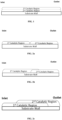
FIG. 2a shows one embodiment according to the present invention, the first catalytic region extends less than 100% of the axial length L, from the inlet end; the second catalytic region extends less than 100% of the axial length L, from the outlet end. The total length of the second and the first catalytic region is equal to the axial length L. -
FIG. 2b shows one embodiment according to the present invention, the first catalytic region extends less than 100% of the axial length L, from the inlet end; the second catalytic region extends 100% of the axial length L, from the outlet end. The total length of the second and the first catalytic region is greater than the axial length L. -
FIG. 2c shows one embodiment according to the present invention, the first catalytic region extends less than 100% of the axial length L, from the inlet end; the second catalytic region extends 100% of the axial length L, from the outlet end. The total length of the second and the first catalytic region is greater than the axial length L. -
FIG. 2d shows one embodiment according to the present invention, the first catalytic region extends less than 100% of the axial length L, from the inlet end; the second catalytic region extends less than 100% of the axial length L, from the outlet end. The total length of the second and the first catalytic region is less than the axial length L. -
FIG. 3a shows one embodiment according to the present invention, the first catalytic region extends less than 100% of the axial length L, from the inlet end; the second catalytic region extends less than 100% of the axial length L, from the outlet end. The total length of the second and the first catalytic region is equal to the axial length L. The 3rd catalytic region extends less than 100% of the axial length L, from the outlet end. -
FIG. 3b shows one embodiment according to the present invention, where the first catalytic region extends 100% of the axial length L, as top layer; the second catalytic region extends 100% of the axial length L, as bottom layer; and the third catalytic region extends 100% of the axial length L, as middle layer. - The present invention is directed to catalytic treatment of exhaust gas, such as that produced by stoichiometric gasoline engines, and to related catalytic articles and systems. More specifically, the invention relates the suppression of ammonia emission and simultaneous treatment of NOx, CO, HC in a vehicular exhaust system.
- One aspect of the present disclosure is directed to a catalyst article for treating exhaust gas from a gasoline engine comprising: a substrate comprising an inlet end, an outlet end with an axial length L; a first catalytic region beginning at the inlet end, wherein the first catalytic region comprises a first zeolite; and a second catalytic region beginning at the outlet end, wherein the second catalytic region comprises a second platinum group metal (PGM) component, a second oxygen storage capacity (OSC) material, and a second inorganic oxide; wherein the second PGM component is selected from the group consisting of palladium, platinum, rhodium and a combination thereof.
- The first zeolite can be a silica-containing zeolite such as a siliceous zeolite, and it also may be referred to an aluminosilicate zeolite, a metal-substituted aluminosilicate zeolite, an aluminophosphate (AIPO) zeolite, a metal-substituted (MeAIPO) zeolite, a silico-aluminophosphate (SAPO), or a metal-substituted silico-aluminophosphate (MeAPSO), or a modified zeolite by Zr, P. It is preferred that the zeolite is an aluminosilicate or silico-aluminophosphate (SAPO) zeolite. More preferably, the zeolite is aluminosilicate.
- The zeolite may be microporous or microporous zeolite, and it is preferably the zeolite has a framework type selected from the group of consisting of ACO, AEI, AEN, AFN, AFT, AFX, ANA, APC, APD, AST, ASV, ATT, BCT, BEA, BEC, BOF, BOG, BRE, CAN, CDO, CFI, CGS, CHA, CHI, CON, DAC, DDR, DFT, EAB, EDI, EPI, ERI, FER, GIS, GOD, IHW, ITE, ITW, LEV, KFI, MER, MFI, MON, NSI, OWE, PAU, PHI, RHO, RTH, SAT, SAV, SIV, THO, TSC, UEI, UFI, VNI, YUG, ZON. Each of the aforementioned three-letter codes represents a framework type in accordance with the "IUPAC Commission on zeolite Nomenclature" and/ or the structure Commission of the international Zeolite Association. More preferably, the first zeolite has a framework type selected from AEI, BEA, CHA, FER, FAU, MFA, or LEV. In some embodiments, the first zeolite can be AEI, BEA, FER, LEV, or CHA. In further embodiments, the first zeolite can be LEV, FER, CHA, or AEI. In yet further embodiment, the first zeolite can be FER, AEI, or CHA. In another further embodiment, the first zeolite can be FER. In another further embodiment, the first zeolite can be AEI. In another further embodiment, the first zeolite can be CHA. In general, the first zeolite may have a silica-to-alumina ratio (SAR) of from 2 to 500, preferably from 4 to 250, and more preferably from 8-150. In some embodiments, the first zeolite is FER or CHA or AEI with SAR range of 8-40. In further embodiments, the first zeolite is FER or CHA or AEI with SAR range of 10-30.
- In certain embodiments, the first catalytic region can further comprise a first transition metal may be selected from the group consisting of Fe, Cu, Co, Mn, Ni, Zn, Ce, Mo, Ag, and a combination of any two or more. In further embodiments, the first transition metal can be selected from Ce, Mn, Cu, Co, Ni or Fe, and a combination of any two or more. In yet other embodiments, the first transition metal can be Cu and/or Fe. In certain embodiments, the first transition metal is 0.01-20 wt.%; preferably, 0.1-15% wt.%; more preferably, 0.5-10% wt.%, based on the weight of the first zeolite; even more preferably, 1-9% wt.% or 2-8% wt.%, based on the weight of the first zeolite.
- In certain embodiments, the first catalytic region can extend for 100% of the axial length L. In other embodiments, the first catalytic region can extend for 30-90%, 40-80%, or 40-60% of the axial length L. Alternatively, the first catalytic region can extend for 30-80% or 30-70% of the axial length L.
- The total washcoat loading of the first catalytic region can be less than 3.5 g/in3, preferably, less than 3.0 g/in3 or 2.5 g/in3. Alternatively, the total washcoat loading of the first catalytic region can be from 0.5 to 3.5 g/in3; preferably, can be from 0.6 to 3 g/in3 or 0.7 to 2.8 g/in3.
- In some embodiments, the second PGM component can be Pd and Rh. In other embodiments, the second PGM component can be Pt and Rh. In yet another embodiment, the second PGM component can be Pt.
- The second OSC material can be cerium oxide, zirconium oxide, a ceria-zirconia mixed oxide, an alumina-ceria-zirconia mixed oxide, or a combination thereof. More preferably, the second OSC material comprises the ceria-zirconia mixed oxide, the alumina-ceria-zirconia mixed oxide, or a combination thereof. In addition, the second OSC material may further comprise one or more of dopants like lanthanum, neodymium, praseodymium, yttrium etc. Moreover, the second OSC material may have the function as a support material for the second PGM component. In some embodiments, the second OSC material comprises the ceria-zirconia mixed oxide and the alumina-ceria-zirconia mixed oxide.
- The ceria-zirconia mixed oxide can have a weight ratio of zirconia dioxide to ceria dioxide at least 50:50, preferably, higher than 60:40, more preferably, higher than 65:35. Alternatively, the ceria-zirconia mixed oxide also can have a weight ratio of ceria dioxide to zirconia dioxide less than 50:50, preferably, less than 40:60, more preferably, less than 35:65.
- The second OSC material (e.g., ceria-zirconia mixed oxide) can be from 10 to 90 wt.%, preferably, 20-90 wt.%, more preferably, 30-90 wt.%, based on the total washcoat loading of the second catalytic region.
- The second OSC material loading in the second catalytic region can be less than 2 g/in3. In some embodiments, the second OSC material loading in the second catalytic region is no greater than 2 g/in3, 1.5 g/in3, 1.2 g/in3, 1.0 g/in3, or 0.8 g/in3.
- The second inorganic oxide is preferably an oxide of Groups 2, 3, 4, 5, 13 and 14 elements. The second inorganic oxide is preferably selected from the group consisting of alumina, zirconia, magnesia, silica, lanthanum, yttrium, neodymium, praseodymium oxides, and mixed oxides or composite oxides thereof. Particularly preferably, the second inorganic oxide is alumina, lanthanum-alumina, zirconia, or a magnesia/alumina composite oxide. One especially preferred second inorganic oxide is alumina or lanthanum-alumina.
- The second OSC material and the second inorganic oxide can have a weight ratio of no greater than 10:1, preferably, no greater than 8:1, more preferably, no greater than 5:1, most preferably, no greater than 4:1.
- Alternatively, the second OSC material and the second inorganic oxide can have a weight ratio of 10:1 to 1:10, preferably, 8:1 to 1:8; more preferably, 5:1 to 1:5; and most preferably, 4:1 to 1:4.
- In some embodiments, the second catalytic region can further comprise a second alkali or alkaline earth metal.
- The second alkali or alkaline earth metal is preferably barium, strontium, mixed oxides or composite oxides thereof. Preferably the barium or strontium, where present, is in an amount of 0.1 to 15 wt.%, and more preferably 3 to 10 wt.% of barium or strontium, based on the total weight of the second catalytic region.
- Preferably the barium or strontium is present as BaCO3 or SrCO3. Such a material can be performed by any method known in the art, for example incipient wetness impregnation or spray-drying.
- In some embodiments, the second catalytic region is substantially free of the second alkali or alkaline earth metal. In further embodiments, the second catalytic region is substantially free of, or does not comprise, the second alkali or alkaline earth metal.
- In certain embodiments, the first catalytic region can extend for 100% of the axial length L. In other embodiments, the second catalytic region can extend for 30 to 90%, 40 to 80%, or 40-70% of the axial length L. Alternatively, the second catalytic region can extend for 40 to 90 percent of the axial length L; preferably, 45 to 60 percent of the axial length L. Alternatively, the second catalytic region can be no greater than 90%, 85%, 80%, or 75% of the axial length L.
- In some embodiments, the second catalytic region can overlap with the first catalytic region. In further embodiments, the second catalytic region can overlap with the first catalytic region for 5 to 40 percent of the axial length L. Preferably, the total length of the second region and the first region is equal or greater than the axial length L. In certain embodiments, the total length of the first catalytic region and the second catalytic region equals to 100% L. In other embodiments, the total length of the first catalytic region and the second catalytic region is less than 100% L, for example, no greater than 99%, 95%, 85%, or 80% of the axial length L.
- In certain embodiments, the second catalytic region can be supported/deposited directly on the substrate.
- The total washcoat loading of the second catalytic region can be less than 3.5 g/in3, preferably, less than 3.0 g/in3 or 2.5 g/in3. Alternatively, the total washcoat loading of the second catalytic region can be from 0.5 to 3.5 g/in3; preferably, can be from 0.6 to 3.5 g/in3 or 0.7 to 3.0 g/in3.
- The catalytic article may further comprise a third catalytic region. In some embodiments, the third catalytic region can begin at the outlet end. In further embodiments, the third catalytic regions can extend for the axial length L. In other embodiments, the third catalytic regions can extend for less than 100% of the axial length L.
- The third catalytic region can further comprise a third PGM component, a third oxygen storage capacity (OSC) material, a third alkali or alkaline earth metal component, and/or a third inorganic oxide.
- The third PGM component can be selected from the group consisting of platinum, palladium, rhodium, and a mixture thereof. In some embodiments, the third PGM component can be palladium, rhodium or a mixture thereof. In another embodiments, the third PGM component can be platinum, rhodium or a mixture thereof.
- The third OSC material can be cerium oxide, zirconium oxide, a ceria-zirconia mixed oxide, an alumina-ceria-zirconia mixed oxide, or a combination thereof. More preferably, the third OSC material comprises the ceria-zirconia mixed oxide, the alumina-ceria-zirconia mixed oxide, or a combination thereof. In addition, the third OSC material may further comprise one or more of dopants like lanthanum, neodymium, praseodymium, yttrium etc. Moreover, the third OSC material may have the function as a support material for the third PGM component. In some embodiments, the third OSC material comprises the ceria-zirconia mixed oxide and the alumina-ceria-zirconia mixed oxide.
- The ceria-zirconia mixed oxide can have a weight ratio of zirconia dioxide to ceria dioxide at least 50:50, preferably, higher than 60:40, more preferably, higher than 65:35. Alternatively, the ceria-zirconia mixed oxide also can have a weight ratio of ceria dioxide to zirconia dioxide less than 50:50, preferably, less than 40:60, more preferably, less than 35:65.
- The third OSC material (e.g., ceria-zirconia mixed oxide) can be from 10 to 90 wt.%, preferably, 25-75 wt.%, more preferably, 30-60 wt.%, based on the total washcoat loading of the third catalytic region.
- The third OSC material loading in the third catalytic region can be less than 2 g/in3. In some embodiments, the third OSC material loading in the second catalytic region is no greater than 2.0 g/in3, 1.5 g/in3, 1.2 g/in3, 1.0 g/in3, or 0.8 g/in3.
- The total washcoat loading of the third catalytic region can be less than 3.5 g/in3, preferably, no more than 3.0 g/in3, 2.5 g/in3, or 2 g/in3.
- The third alkali or alkaline earth metal is preferably barium, strontium, mixed oxides or composite oxides thereof. Preferably the barium or strontium, where present, is in an amount of 0.1 to 15 wt.%, and more preferably 3 to 10 wt.% of barium or strontium, based on the total weight of the third catalytic region.
- It is even more preferable that the third alkali or alkaline earth metal is barium. The barium, where present, is preferably present in an amount of 0.1 to 15 wt.%, and more preferably 3 to 10 wt.%, based on the total weight of the third catalytic region.
- It is also preferable that the third alkali or alkaline earth metal is mixed oxides or composite oxide of barium and strontium. Preferably, the mixed oxides or composite oxide of barium and strontium is present in an amount of 0.1 to 15 wt.%, and more preferably 3 to 10 wt.%, based on the total weight of the third catalytic region. It is more preferable that the third alkali or alkaline earth metal is composite oxide of barium and strontium.
- Preferably the barium or strontium is present as BaCO3 or SrCO3. Such a material can be performed by any method known in the art, for example incipient wetness impregnation or spray-drying.
- In some embodiments, the third catalytic region is substantially free of the third alkali or alkaline earth metal. In further embodiments, the third catalytic region is substantially free of, or does not comprise, the third alkali or alkaline earth metal.
- The third inorganic oxide is preferably an oxide of Groups 2, 3, 4, 5, 13 and 14 elements. The third inorganic oxide is preferably selected from the group consisting of alumina, zirconia, magnesia, silica, lanthanum, neodymium, praseodymium, yttrium oxides, and mixed oxides or composite oxides thereof. Particularly preferably, the third inorganic oxide is alumina, lanthanum-alumina, zirconia, or a magnesia/alumina composite oxide. One especially preferred third inorganic oxide is alumina or lanthanum-alumina.
- The third OSC material and the third inorganic oxide can have a weight ratio of no greater than 10:1, preferably, no greater than 8:1 or 5:1, more preferably, no greater than or 5:1, most preferably, no greater than 4:1.
- Alternatively, the third OSC material and the third inorganic oxide can have a weight ratio of 10:1 to 1:10, preferably, 8:1 to 1:8; or, more preferably, 5:1 to 1:5 or; and most preferably, 4:1 to 1:4.
- The third catalytic region can extend for 100 percent of the axial length L (e.g., see
FIG. 3b ). Alternatively, the third catalytic region can be less than the axial length L, for example, no greater than 95%, 90%, 80%, or 70% of the axial length L (e.g., seeFIG. 3a ). - Preferably the substrate is a flow-through monolith.
- The substrate can be less than 8 inches in length, preferably from 2 to 6 inches.
- The flow-through monolith substrate has a first face and a second face defining a longitudinal direction there between. The flow-through monolith substrate has a plurality of channels extending between the first face and the second face. The plurality of channels extends in the longitudinal direction and provide a plurality of inner surfaces (e.g., the surfaces of the walls defining each channel). Each of the plurality of channels has an opening at the first face and an opening at the second face. For the avoidance of doubt, the flow-through monolith substrate is not a wall flow filter.
- The first face is typically at an inlet end of the substrate and the second face is at an outlet end of the substrate.
- The channels may be of a constant width and each plurality of channels may have a uniform channel width.
- Preferably within a plane orthogonal to the longitudinal direction, the monolith substrate has from 300 to 900 channels per square inch, preferably from 400 to 800. For example, on the first face, the density of open first channels and closed second channels is from 600 to 700 channels per square inch. The channels can have cross sections that are rectangular, square, circular, oval, triangular, hexagonal, or other polygonal shapes.
- The monolith substrate acts as a support for holding catalytic material. Suitable materials for forming the monolith substrate include ceramic-like materials such as cordierite, silicon carbide, silicon nitride, zirconia, mullite, spodumene, alumina-silica magnesia or zirconium silicate, or of porous, refractory metal. Such materials and their use in the manufacture of porous monolith substrates are well known in the art.
- It should be noted that the flow-through monolith substrate described herein is a single component (i.e., a single brick). Nonetheless, when forming an emission treatment system, the substrate used may be formed by adhering together a plurality of channels or by adhering together a plurality of smaller substrates as described herein. Such techniques are well known in the art, as well as suitable casings and configurations of the emission treatment system.
- In embodiments wherein the catalyst article of the present comprises a ceramic substrate, the ceramic substrate may be made of any suitable refractory material, e.g., alumina, silica, ceria, zirconia, magnesia, zeolites, silicon nitride, silicon carbide, zirconium silicates, magnesium silicates, aluminosilicates and metalloid aluminosilicates (such as cordierite and spodumene), or a mixture or mixed oxide of any two or more thereof. Cordierite, a magnesium aluminosilicate, and silicon carbide are particularly preferred.
- In embodiments wherein the catalyst article of the present invention comprises a metallic substrate, the metallic substrate may be made of any suitable metal, and in particular heat-resistant metals and metal alloys such as titanium and stainless steel as well as ferritic alloys containing iron, nickel, chromium, and/or aluminum in addition to other trace metals.
- In some embodiments, the first catalytic region can be located on a different substrate than the second (or optionally the third) catalytic region.
- Another aspect of the present disclosure is directed to a method for treating a vehicular exhaust gas from a gasoline engine containing NOx, CO, HC, and ammonia using the catalyst article described herein. The testing catalysts made according to this invention showed significantly improved NH3 control performance compared to with conventional TWC (e.g., see Example 4; and Tables 9 and 10).
- Another aspect of the present disclosure is directed to a system for treating vehicular exhaust gas comprising the catalyst article described herein in conjunction with a conduit for transferring the exhaust gas through the system.
- In some embodiments, the system can further comprise a TWC article. In further embodiments, the TWC article is upstream of the catalyst article of the first aspect. In certain embodiments, the upstream TWC article and the catalyst article of the first aspect can be on different substrates. In other embodiments, the upstream TWC article and the catalyst article of the first aspect can be on the same substrate.
- The term "region" as used herein refers to an area on a substrate, typically obtained by drying and/or calcining a washcoat. A "region" can, for example, be disposed or supported on a substrate as a "layer" or a "zone". The area or arrangement on a substrate is generally controlled during the process of applying the washcoat to the substrate. The "region" typically has distinct boundaries or edges (i.e. it is possible to distinguish one region from another region using conventional analytical techniques).
- Typically, the "region" has a substantially uniform length. The reference to a "substantially uniform length" in this context refers to a length that does not deviate (e.g. the difference between the maximum and minimum length) by more than 10 %, preferably does not deviate by more than 5 %, more preferably does not deviate by more than 1 %, from its mean value.
- It is preferable that each "region" has a substantially uniform composition (i.e. there is no substantial difference in the composition of the washcoat when comparing one part of the region with another part of that region). Substantially uniform composition in this context refers to a material (e.g. region) where the difference in composition when comparing one part of the region with another part of the region is 5% or less, usually 2.5% or less, and most commonly 1% or less.
- The term "zone" as used herein refers to a region having a length that is less than the total length of the substrate, such as ≤ 75 % of the total length of the substrate. A "zone" typically has a length (i.e. a substantially uniform length) of at least 5% (e.g. ≥ 5 %) of the total length of the substrate.
- The total length of a substrate is the distance between its inlet end and its outlet end (e.g. the opposing ends of the substrate).
- Any reference to a "zone disposed at an inlet end of the substrate" used herein refers to a zone disposed or supported on a substrate where the zone is nearer to an inlet end of the substrate than the zone is to an outlet end of the substrate. Thus, the midpoint of the zone (i.e. at half its length) is nearer to the inlet end of the substrate than the midpoint is to the outlet end of the substrate. Similarly, any reference to a "zone disposed at an outlet end of the substrate" used herein refers to a zone disposed or supported on a substrate where the zone is nearer to an outlet end of the substrate than the zone is to an inlet end of the substrate. Thus, the midpoint of the zone (i.e. at half its length) is nearer to the outlet end of the substrate than the midpoint is to the inlet end of the substrate.
- When the substrate is a wall-flow filter, then generally any reference to a "zone disposed at an inlet end of the substrate" refers to a zone disposed or supported on the substrate that is:
- (a) nearer to an inlet end (e.g. open end) of an inlet channel of the substrate than the zone is to a closed end (e.g. blocked or plugged end) of the inlet channel, and/or
- (b) nearer to a closed end (e.g. blocked or plugged end) of an outlet channel of the substrate than the zone is to an outlet end (e.g. open end) of the outlet channel.
- Similarly, any reference to a "zone disposed at an outlet end of the substrate" when the substrate is a wall-flow filter refers to a zone disposed or supported on the substrate that is:
- (a) nearer to an outlet end (e.g. an open end) of an outlet channel of the substrate than the zone is to a closed end (e.g. blocked or plugged) of the outlet channel, and/or
- (b) nearer to a closed end (e.g. blocked or plugged end) of an inlet channel of the substrate than it is to an inlet end (e.g. an open end) of the inlet channel.
- Thus, the midpoint of the zone (i.e. at half its length) is (a) nearer to an outlet end of an outlet channel of the substrate than the midpoint is to the closed end of the outlet channel, and/or (b) nearer to a closed end of an inlet channel of the substrate than the midpoint is to an inlet end of the inlet channel.
- A zone may satisfy both (a) and (b) when the washcoat is present in the wall of the wall-flow filter (i.e. the zone is in-wall).
- The term "washcoat" is well known in the art and refers to an adherent coating that is applied to a substrate usually during production of a catalyst.
- The acronym "PGM" as used herein refers to "platinum group metal". The term "platinum group metal" generally refers to a metal selected from the group consisting of Ru, Rh, Pd, Os, Ir and Pt, preferably a metal selected from the group consisting of Ru, Rh, Pd, Ir and Pt. In general, the term "PGM" preferably refers to a metal selected from the group consisting of Rh, Pt and Pd.
- The term "mixed oxide" as used herein generally refers to a mixture of oxides in a single phase, as is conventionally known in the art. The term "composite oxide" as used herein generally refers to a composition of oxides having more than one phase, as is conventionally known in the art.
- The expression "consist essentially" as used herein limits the scope of a feature to include the specified materials or steps, and any other materials or steps that do not materially affect the basic characteristics of that feature, such as for example minor impurities. The expression "consist essentially of' embraces the expression "consisting of".
- The expression "substantially free of' as used herein with reference to a material, typically in the context of the content of a region, a layer or a zone, means that the material in a minor amount, such as ≤ 5 % by weight, preferably ≤ 2 % by weight, more preferably ≤ 1 % by weight. The expression "substantially free of' embraces the expression "does not comprise."
- The expression "essentially free of' as used herein with reference to a material, typically in the context of the content of a region, a layer or a zone, means that the material in a trace amount, such as ≤ 1 % by weight, preferably ≤ 0.5 % by weight, more preferably ≤ 0.1 % by weight. The expression "essentially free of' embraces the expression "does not comprise."
- Any reference to an amount of dopant, particularly a total amount, expressed as a % by weight as used herein refers to the weight of the support material or the refractory metal oxide thereof.
- The term "loading" as used herein refers to a measurement in units of g/ft3 on a metal weight basis.
- The following examples merely illustrate the invention. Those skilled in the art will recognize many variations that are within the spirit of the invention and scope of the claims.
- All materials are commercially available and were obtained from the known suppliers, unless noted otherwise.
- A catalyst with a single layer was prepared. The layer consists of Fe, which supported on a FER type of zeolite with SAR range ~ 17 and binder, the total washcoat loading of the single layer was about 1.6 g/in3 with Fe loading of about 3 wt.% (based on the weight of FER).
- The washcoat was coated on a ceramic substrate (400 cpsi, 4 mil wall thickness) using standard coating procedures.
- A catalyst with a single layer was prepared. The layer consists of an AEI type of zeolite with SAR range ~ 20 and binder, the total washcoat loading of the single layer was about 1.6 g/in3.
- The washcoat was coated on a ceramic substrate (400 cpsi, 4 mil wall thickness) using standard coating procedures.
- A catalyst with a single layer was prepared. The layer consists of Cu, which supported on an AEI type of zeolite with SAR range ~ 20 and binder, the total washcoat loading of the single layer was about 1.6 g/in3 with Cu loading of about 2 wt.% (based on the weight of AEI).
- The washcoat was coated on a ceramic substrate (400 cpsi, 4 mil wall thickness) using standard coating procedures.
- A catalyst with a single layer was prepared. The layer consists of Cu, which supported on an AEI type of zeolite with SAR range ~ 17 and binder, the total washcoat loading of the single layer was about 1.6 g/in3 with Cu loading of about 4 wt.% (based on the weight of AEI).
- The washcoat was coated on a ceramic substrate (400 cpsi, 4 mil wall thickness) using standard coating procedures.
- Catalysts A-D were aged under hydrocarbon (HC) redox conditions as shown in Table 1 at 850 °C for 4 hours.
Table 1 HC Redox Aging Conditions Perturbation Cycle 80s [Rich λ=0.98], 20s [Lean] Rich Gas Condition 0.25% C3H6, 1.0% O2, 10.0% H2O, N2 Balance Lean Gas Condition 21% O2, 10% H2O, N2 Balance Flow Rate 2.0 L/min - After HC redox aging, Catalysts A-D were tested for their NH3 storage performance under testing protocol as shown in Table 2.
Table 2 NH3 Storage Testing Protocol Precondition Increase temperature to 500 °C at 25 °C/min under N2 gas Pre-Storage Decrease temperature to 150 °C and hold for 3 min under N2 gas Storage Flow gas with 1000 ppm NH3, 10% H2O, N2 balance for 10 min - As shown in Table 3 below, while Catalyst B demonstrate its NH3 storage capacity, Catalysts A, C, and D showed superior/improved NH3 storage capacity when compared with Catalyst B.
Table 3 NH3 Storage Testing for Aged Catalysts A-D NH3 Storage Capacity Grams per liter of catalyst volume Catalyst A 0.71 Catalyst B 0.41 Catalyst C 1.14 Catalyst D 1.45 - After HC redox aging, Catalysts A-D were tested for their hot NH3 conversion performance under testing protocol as shown in Table 4.
Table 4 Hot NH3 Test Protocol with STOICH NH3 FEED Precondition Increase temperature to 400 °C at 25 °C/min under 20% O2, N2 Balance Hold for 3 min under the same gas condition and temperature Switch gas to N2 and keep for 5min Hot NH3 Test Switching Gas Condition: 1) 20% O2, N2 Balance for 30s 2) N2 for 15s 3) NH3 Feed (λ=1) 1000ppm NH3, 500ppmC C3H6, 15% CO2, 10% H2O, N2 Balance for 20s 4) N2 for 15s 5) NO Feed (λ=1.03) 1000ppm NO, 0.6% O2, 15% CO2, 10% H2O, N2 Balance for 20s 6) N2 for 5min 7) Repeat test cycle multiple times: NH3 and NO conversions are calculated (average) - As shown in Table 5 below, Catalysts A, C, and D demonstrated good NH3 and NO conversions under stoichiometric feed conditions.
Table 5 Hot NH3 Conversion Testing for Aged Catalysts A-D NH3 Conversion (%) NO Conversion (%) Catalyst A 23 27 Catalyst B 0 5 Catalyst C 74 69 Catalyst D 95 74 - Catalysts A and D were aged under different conditions as shown in Table 6 at 850 °C for 4 hours.
Table 6 Aging Conditions Perturbation Cycle 5 min [Stoich], 1 min [Lean] Stoich Gas Condition 10% H2O, N2 Balance Lean Gas Condition 20% O2, 10% H2O, N2 Balance Flow Rate 3 L/min - After aging, Catalysts A and D were tested for their hot NH3 conversion performance under testing protocol as shown in Table 7.
Table 7 Hot NH3 Test Protocol with RICH NH3 FEED Precondition Increase temperature to 400 °C at 25 °C/min under 20% O2, N2 Balance Hold for 3 min under the same gas condition and temperature Switch gas to N2 and keep for 5min Hot NH3 Test Switching Gas Condition: 1) 20% O2, N2 Balance for 30s 2) N2 for 15s 3) NH3 Feed (λ=0.92) 1000ppm NH3, 1260ppmC C3H6, 2.4% CO, 15% CO2, 10% H2O, N2 Balance for 20s 4) N2 for 15s 5) NO Feed (λ=1) 1000ppm NO, 1260ppmC C3H6, 0.6% O2, 1% CO, 15% CO2, 10% H2O, N2 Balance for 20s 6) N2 for 5min 7) Repeat test cycle multiple times: NH3 and NO conversions are calculated (average) - As shown in Table 8 below, Catalysts A and D demonstrated good NH3 and NO conversions under rich feed conditions.
Table 8 Hot NH3 Conversion Testing for Aged Catalysts A and D NH3 Conversion (%) NO Conversion (%) Catalyst A 18 13 Catalyst D 96 39 - TWC-1 is a typical three-way (Pd-Rh) catalyst with a double-layered structure in two catalytic regions as shown in
FIG. 1 . Bottom layer consists of Pd supported on a washcoat of a first CeZr mixed oxide, La-stabilized alumina, Ba promotor. The washcoat loading of the bottom layer was about 2.0 g/in3 with a Pd loading of 16 g/ft3. The washcoat was coated from each end face of a ceramic substrate (400 cpsi, 4.3 mil wall thickness) using standard coating procedures with coating depth targeted of 50% of the substrate length, dried at 100 °C and calcined at 500 °C for 45mins. - Top layer consists of Rh supported on a washcoat of a second CeZr mixed oxide, La-stabilized alumina. The washcoat loading of the second layer was about 1.5 g/in3 with a Rh loading of 4 g/ft3. This second washcoat was then coated from each end face of the ceramic substrate containing the bottom layer from above, using standard coating procedures with coating depth targeted of 50% of the substrate length, dried at 100 °C and calcined at 500 °C for 45mins.
- TWC-2 is a typical three-way (Pd-Rh) catalyst with a single-layered structure. The catalyst layer consists of Pd and Rh supported on a washcoat of a first CeZr mixed oxide, La-stabilized alumina, Ba promotor. The washcoat loading of the layer was about 3.0 g/in3 with Pd loading of 2 g/ft3 and Rh loading of 8 g/ft3. The washcoat was coated from each end face of a ceramic substrate (400 cpsi, 4.3 mil wall thickness) using standard coating procedures with coating depth targeted of 50% of the substrate length, dried at 100 °C and calcined at 500 °C for 45 mins.
- A catalyst with two catalytic regions were prepared. (E.g., see
FIG. 2a ). - The first catalytic region consists of Fe, which supported on a FER type of zeolite with SAR range ~ 16-20 and binder, the total washcoat loading of this catalytic region was about 1.5 g/in3 with Fe loading of about 3 wt.% (based on the weight of FER).
- The washcoat of first catalytic region was coated from the inlet end face of a ceramic substrate (400 cpsi, 4.3 mil wall thickness) using standard coating procedures with coating depth targeted of 50% of the substrate length.
- The washcoat of the second catalytic region consists of La-alumina, ceria-zirconia mixed oxide, platinum, rhodium (about 3.0 g/in3 with Pt loading of 6.7 g/ft3 and Rh loading of 3.3 g/ft3). The washcoat was coated from the outlet end face of the ceramic substrate containing the first catalytic region from above, using standard coating procedures with coating depth targeted of 50% of the substrate length.
- The catalyst article was dried at 100 °C and calcined at 500 °C for 45 mins.
- A catalyst with two catalytic regions were prepared. (E.g., see
FIG. 2a ). - The first catalytic region consists of Fe, which supported on a FER type of zeolite with SAR range ~ 16-20 and binder, the total washcoat loading of this catalytic region was about 1.5 g/in3 with Fe loading of about 3 wt.% (based on the weight of FER).
- The washcoat of first catalytic region was coated from the inlet end face of a ceramic substrate (400 cpsi, 4.3 mil wall thickness) using standard coating procedures with coating depth targeted of 50% of the substrate length.
- The washcoat of the second catalytic region consists of La-alumina, ceria-zirconia mixed oxide, platinum (about 3.0 g/in3 with Pt loading of 10 g/ft3). The washcoat was coated from the outlet end face of the ceramic substrate containing the first catalytic region from above, using standard coating procedures with coating depth targeted of 50% of the substrate length.
- The catalyst article was dried at 100 °C and calcined at 500 °C for 45 mins.
- A catalyst with two catalytic regions were prepared. (E.g., see
FIG. 2a ). - The first catalytic region consists of Fe, which supported on a FER type of zeolite with SAR range ~ 16-20 and binder, the total washcoat loading of this catalytic region was about 1.5 g/in3 with Fe loading of about 3 wt.% (based on the weight of FER).
- The washcoat of first catalytic region was coated from the inlet end face of a ceramic substrate (400 cpsi, 4.3 mil wall thickness) using standard coating procedures with coating depth targeted of 50% of the substrate length.
- The washcoat of the second catalytic region consists of La-alumina, ceria, platinum, rhodium (about 3.0 g/in3 with Pt loading of 6.7 g/ft3 and Rh loading of 3.3 g/ft3). The washcoat was coated from the outlet end face of the ceramic substrate containing the first catalytic region from above, using standard coating procedures with coating depth targeted of 50% of the substrate length.
- The catalyst article was dried at 100 °C and calcined at 500 °C for 45 mins.
- A catalyst with two catalytic regions were prepared. (E.g., see
FIG. 1 ). - The first catalytic region consists of Fe, which supported on a FER type of zeolite with SAR range ~ 16-20 and binder, the total washcoat loading of this catalytic region was about 1.5 g/in3 with Fe loading of about 3 wt.% (based on the weight of FER).
- The washcoat of first catalytic region was coated from the both the inlet and outlet end face of a ceramic substrate (400 cpsi, 4.3 mil wall thickness) using standard coating procedures with coating depth targeted of 50% of the substrate length to give full coverage of the ceramic substrate.
- The washcoat of the second catalytic region consists of La-alumina, ceria-zirconia mixed oxide, platinum, rhodium (about 3.0 g/in3 with Pt loading of 6.7 g/ft3 and Rh loading of 3.3 g/ft3). The washcoat of second catalytic region was coated from the both the inlet and outlet end face of a ceramic substrate (400 cpsi, 4.3 mil wall thickness) using standard coating procedures with coating depth targeted of 50% of the substrate length to give full coverage of the ceramic substrate.
- The catalyst article was dried at 100 °C and calcined at 500 °C for 45 mins.
- Catalyst performance testing was carried out with a synthetic exhaust gas and Catalyst samples were aged at 800 °C for 10 hours in an 10% water, 5% O2, balance N2.
- A catalyst with two catalytic regions were prepared. (E.g., see
FIG. 2a ). - The first catalytic region consists of Cu, which supported on a CHA type of zeolite with SAR range ~ 16 and binder, the total washcoat loading of this catalytic region was about 1.5 g/in3 with Cu loading of about 3.3 wt.% (based on the weight of CHA).
- The washcoat of first catalytic region was coated from the inlet end face of a ceramic substrate (400 cpsi, 4.3 mil wall thickness) using standard coating procedures with coating depth targeted of 50% of the substrate length.
- As described in Catalyst Article 2.
- The catalyst article was dried at 100 °C and calcined at 500 °C for 45 mins.
- A catalyst with two catalytic regions were prepared. (E.g., see
FIG. 2a ). - The first catalytic region consists of Cu, which supported on an AEI type of zeolite with SAR range ~ 20 and binder, the total washcoat loading of this catalytic region was about 1.2 g/in3 with Cu loading of about 3.8 wt.% (based on the weight of AEI).
- The washcoat of first catalytic region was coated from the inlet end face of a ceramic substrate (400 cpsi, 4.3 mil wall thickness) using standard coating procedures with coating depth targeted of 50% of the substrate length.
- As described in Catalyst Article 2.
- The catalyst article was dried at 100 °C and calcined at 500 °C for 45 mins.
- A catalyst with two catalytic regions were prepared. (E.g., see
FIG. 2a ). - The first catalytic region consists of Cu, which supported on an AEI type of zeolite with SAR range ~ 20 and binder, the total washcoat loading of this catalytic region was about 1.5 g/in3 with Cu loading of about 3.8 wt.% (based on the weight of AEI).
- The washcoat of first catalytic region was coated from the inlet end face of a ceramic substrate (400 cpsi, 4.3 mil wall thickness) using standard coating procedures with coating depth targeted of 50% of the substrate length.
- As described in Catalyst Article 2.
- The catalyst article was dried at 100 °C and calcined at 500 °C for 45 mins.
- A catalyst with two catalytic regions were prepared. (E.g., see
FIG. 2a ). - The first catalytic region consists of Cu, which supported on an AEI type of zeolite with SAR range ~ 20 and binder, the total washcoat loading of this catalytic region was about 2.2 g/in3 with Cu loading of about 3.8 wt.% (based on the weight of AEI).
- The washcoat of first catalytic region was coated from the inlet end face of a ceramic substrate (400 cpsi, 4.3 mil wall thickness) using standard coating procedures with coating depth targeted of 50% of the substrate length.
- As described in Catalyst Article 2.
- The catalyst article was dried at 100 °C and calcined at 500 °C for 45 mins.
- A catalyst with two catalytic regions were prepared. (E.g., see
FIG. 2a ). - The first catalytic region consists of Cu, which supported on an AEI type of zeolite with SAR range ~ 20 and binder, the total washcoat loading of this catalytic region was about 2.8 g/in3 with Cu loading of about 3.8 wt.% (based on the weight of AEI).
- The washcoat of first catalytic region was coated from the inlet end face of a ceramic substrate (400 cpsi, 4.3 mil wall thickness) using standard coating procedures with coating depth targeted of 50% of the substrate length.
- As described in Catalyst Article 2.
- The catalyst article was dried at 100 °C and calcined at 500 °C for 45 mins.
Catalyst performance testing was carried out with a synthetic exhaust gas and Catalyst samples were aged at 800 °C for 10 hours in an 10% water, 5% O2, balance N2. - A catalyst sample was heated to 150 °C and a gas feed of 400 ppm of NH3, 10% water, balance N2. The space velocity was 110k h-1. The total amount of NH3 stored at the point the catalyst was saturated with NH3 was recorded.
- The catalyst sample saturated with NH3 was heated from 100 °C to 500 °C at 50 °C per minute with a gas mixture of 300 ppm NH3, 0.5% O2, 300 ppm NO, balance N2. The temperature at which NH3 conversion reached 50% was recorded.
- The catalyst performance results from TWC-2, Catalyst Articles 1-9 are shown in Table 9. The ammonia storage capacities of Catalyst Articles 1-4 are comparable and significantly higher than the TWC-2 technology. Catalyst Articles 6-9 show increasing Cu zeolite loading increases the amount of ammonia storage. The NH3 oxidation light off for Catalyst Articles 1-9 are significantly lower than TWC-2. These results show that conventional TWC technology is not as effective and control NH3 emissions as the Catalyst Articles 1-9.
Table 9 NH3 Storage and Oxidation from Synthetic Exhaust Testing NH3 Storage Capacity Grams per liter of catalyst volume NH3 Oxidation Light Off Temperature, T50 (°C) TWC-2 0.12 501 Catalyst Article 1 0.34 371 Catalyst Article 2 0.35 290 Catalyst Article 3 0.33 461 Catalyst Article 4 0.36 375 Catalyst Article 5 0.80 267 Catalyst Article 6 0.74 275 Catalyst Article 7 0.95 238 Catalyst Article 8 1.37 301 Catalyst Article 9 2.60 349 - The following Systems were tested for their catalytic performances with the layout of TWC-1 at upstream, and TWC-2 at downstream:
- Comparative System 1: TWC-1 only
- Comparative System 2: TWC-1 + TWC-2
- System 3: TWC-1 + TWC-2 + Catalyst Article 2
- Catalyst performance testing was carried out by on a gasoline vehicle under a Real Driving Emission (RDE) representative drive cycle. The RDE test was considered as a reliable way of emission evaluation for engine operation. The final RDE emission value is the sum of emissions divided by the distance driven. The vehicle used was a Euro 6d full certified vehicle with a 1.5 L turbo charged direct injection engine. The catalyst system was aged to represent end of useful life using a fuel cut aging cycle with a target inlet temperature for TWC-1 of 950 °C for 60 hours. The temperature of the catalysts downstream of TWC-1 during this aging was 830 °C.
- The emission results on a gasoline vehicle under RDE cycle toward Comparative System 1 and Comparative System 2 were shown in Table 10. The results exhibited that NH3 emission of Comparative Catalyst Systems 1 and 2 both failed to meet the anticipated European Light Duty NH3 requirement of 10 mg/km. Therefore, Comparative Systems 1 and 2, using typical catalysts in gasoline applications, does not work for NH3 emission requirements. The addition of Catalyst Article 2 of the present invention to System 3 (shown in Table 10) is effective at controlling NH3 emissions to below the anticipated European requirement for light duty vehicles.
Table 10 Emission results on a gasoline vehicle under RDE cycle System Catalyst Article Arrangement Emissions on natural gas engine (g/km) CO/10 THC NOx NH3 Comparative System 1 TWC-1 only 0.120 0.078 0.117 0.024 Comparative System 2 TWC-1 + TWC-2 0.034 0.045 0.037 0.012 System 3 TWC-1 + TWC-2 + Catalyst Article 2 0.031 0.036 0.035 0.005 Anticipated European Light Duty Vehicle NH3 Requirement - - - 0.010
Claims (15)
- A catalyst article for treating exhaust gas from a gasoline engine comprising:a substrate comprising an inlet end, an outlet end with an axial length L;a first catalytic region beginning at the inlet end, wherein the first catalytic region comprises a first zeolite; anda second catalytic region beginning at the outlet end, wherein the second catalytic region comprises a second platinum group metal (PGM) component, a second oxygen storage capacity (OSC) material, and a second inorganic oxide;wherein the second PGM component is selected from the group consisting of palladium, platinum, rhodium and a combination thereof.
- The catalyst article of claim 1, wherein the first catalytic region extends for 30 to 90 percent of the axial length L.
- The catalyst article of claim 1 or claim 2, wherein the second catalytic region extends for 30 to 90 percent of the axial length L.
- The catalyst article of any one of the preceding claims, wherein the second catalytic region overlaps with the first catalytic region.
- The catalyst article of any one of claims 1-3, wherein the second catalytic region does not overlap with the first catalytic region.
- The catalyst article of any one of the preceding claims, wherein the first catalytic region further comprises a first transition metal selected from the group consisting of Fe, Cu, Mn, Co, Ni, Zn and a combination thereof.
- The catalyst article of claim 6, wherein the first transition metal is Cu and/or Fe.
- The catalyst article of claim 7, wherein Fe is 0.01-20 wt.%, based on the weight of the first zeolite.
- The catalyst article of claim 7, wherein Cu is 0.01-20 wt.%, based on the weight of the first zeolite.
- The catalyst article of any one of the preceding claims, wherein the first zeolite has a framework type selected from the group of consisting of ACO, AEI, AEN, AFN, AFT, AFX, ANA, APC, APD, AST, ASV, ATT, BCT, BEA, BEC, BOF, BOG, BRE, CAN, CDO, CFI, CGS, CHA, CHI, CON, DAC, DDR, DFT, EAB, EDI, EPI, ERI, FER, GIS, GOD, IHW, ITE, ITW, LEV, KFI, MER, MFI, MON, NSI, OWE, PAU, PHI, RHO, RTH, SAT, SAV, SIV, THO, TSC, UEI, UFI, VNI, YUG, ZON.
- The catalyst article of claim 10, wherein the first zeolite has a framework type selected from AEI, BEA, CHA, FER, FAU, MFA, or LEV.
- The catalyst article of any one of the preceding claims, wherein the substrate is a flow-through monolith or a wall flow filter.
- An emission treatment system for treating a flow of a gasoline engine exhaust gas comprising the catalyst article of any one of claims 1-12.
- The emission treatment system of claim 13, further comprising a TWC article, which is upstream of the catalyst article.
- A method of treating an exhaust gas from a gasoline engine comprising contacting the exhaust gas with the catalyst article of any one of claims 1-12.
Applications Claiming Priority (2)
| Application Number | Priority Date | Filing Date | Title |
|---|---|---|---|
| US202163263390P | 2021-11-02 | 2021-11-02 | |
| US202263377415P | 2022-09-28 | 2022-09-28 |
Publications (1)
| Publication Number | Publication Date |
|---|---|
| EP4173693A1 true EP4173693A1 (en) | 2023-05-03 |
Family
ID=84043852
Family Applications (1)
| Application Number | Title | Priority Date | Filing Date |
|---|---|---|---|
| EP22203988.5A Pending EP4173693A1 (en) | 2021-11-02 | 2022-10-27 | Catalysts for gasoline exhaust gas treatments with improved ammonia emission control |
Country Status (3)
| Country | Link |
|---|---|
| US (1) | US20230143941A1 (en) |
| EP (1) | EP4173693A1 (en) |
| WO (1) | WO2023079264A1 (en) |
Families Citing this family (1)
| Publication number | Priority date | Publication date | Assignee | Title |
|---|---|---|---|---|
| CN115957754A (en) * | 2021-10-12 | 2023-04-14 | 庄信万丰(上海)化工有限公司 | Novel zoned catalyst for CNG engine exhaust treatment with improved ammonia emission control |
Citations (8)
| Publication number | Priority date | Publication date | Assignee | Title |
|---|---|---|---|---|
| JPH08281107A (en) * | 1995-04-11 | 1996-10-29 | Nissan Motor Co Ltd | Catalyst for purifying exhaust gas |
| EP2153896A1 (en) * | 2008-07-31 | 2010-02-17 | Honda Motor Co., Ltd | NOx purification catalyst |
| US20110030346A1 (en) * | 2009-08-05 | 2011-02-10 | Basf Se | Treatment System for Gasoline Engine Exhaust Gas |
| US20160047286A1 (en) * | 2014-08-12 | 2016-02-18 | Johnson Matthey Public Limited Company | EXHAUST SYSTEM WITH A MODIFIED LEAN NOx TRAP |
| US20180169624A1 (en) * | 2016-12-15 | 2018-06-21 | Johnson Matthey Public Limited Company | NOx ADSORBER CATALYST |
| US20190143311A1 (en) * | 2016-06-23 | 2019-05-16 | N.E. Chemcat Corporation | Catalyst for lean burn |
| US20190353068A1 (en) * | 2018-05-18 | 2019-11-21 | Umicore Ag & Co. Kg | Exhaust emission reduction system having an hc-trap and nox-trap combination designed for operating under strategic lean conditions |
| US20190351397A1 (en) * | 2018-05-18 | 2019-11-21 | Umicore Ag & Co. Kg | Hydrocarbon trap catalyst |
Family Cites Families (2)
| Publication number | Priority date | Publication date | Assignee | Title |
|---|---|---|---|---|
| JP5122195B2 (en) * | 2007-07-17 | 2013-01-16 | 本田技研工業株式会社 | NOx purification catalyst |
| JP2018526195A (en) * | 2015-06-16 | 2018-09-13 | ビーエーエスエフ ソシエタス・ヨーロピアBasf Se | SCR catalyzed soot filter with integrated lean NOx trap catalyst for use in passive selective catalytic reduction |
-
2022
- 2022-10-27 WO PCT/GB2022/052726 patent/WO2023079264A1/en active Application Filing
- 2022-10-27 US US18/050,067 patent/US20230143941A1/en active Pending
- 2022-10-27 EP EP22203988.5A patent/EP4173693A1/en active Pending
Patent Citations (8)
| Publication number | Priority date | Publication date | Assignee | Title |
|---|---|---|---|---|
| JPH08281107A (en) * | 1995-04-11 | 1996-10-29 | Nissan Motor Co Ltd | Catalyst for purifying exhaust gas |
| EP2153896A1 (en) * | 2008-07-31 | 2010-02-17 | Honda Motor Co., Ltd | NOx purification catalyst |
| US20110030346A1 (en) * | 2009-08-05 | 2011-02-10 | Basf Se | Treatment System for Gasoline Engine Exhaust Gas |
| US20160047286A1 (en) * | 2014-08-12 | 2016-02-18 | Johnson Matthey Public Limited Company | EXHAUST SYSTEM WITH A MODIFIED LEAN NOx TRAP |
| US20190143311A1 (en) * | 2016-06-23 | 2019-05-16 | N.E. Chemcat Corporation | Catalyst for lean burn |
| US20180169624A1 (en) * | 2016-12-15 | 2018-06-21 | Johnson Matthey Public Limited Company | NOx ADSORBER CATALYST |
| US20190353068A1 (en) * | 2018-05-18 | 2019-11-21 | Umicore Ag & Co. Kg | Exhaust emission reduction system having an hc-trap and nox-trap combination designed for operating under strategic lean conditions |
| US20190351397A1 (en) * | 2018-05-18 | 2019-11-21 | Umicore Ag & Co. Kg | Hydrocarbon trap catalyst |
Also Published As
| Publication number | Publication date |
|---|---|
| WO2023079264A1 (en) | 2023-05-11 |
| US20230143941A1 (en) | 2023-05-11 |
Similar Documents
| Publication | Publication Date | Title |
|---|---|---|
| US11439987B2 (en) | Multi-region TWC for treatment of exhaust gas from gasoline engine | |
| EP3848564B1 (en) | Catalyst | |
| EP3889404A1 (en) | Multi-region twc catalysts for gasoline engine exhaust gas treatments with improved h2s attenuation | |
| US11364485B2 (en) | Multi-region catalysts for CNG engine exhaust gas treatments with improved ammonia leakage control | |
| EP3722571A1 (en) | Novel three-zone two-layer twc catalyst in gasoline waste gas applications | |
| WO2020065573A1 (en) | Novel twc catalysts for gasoline exhaust gas applications | |
| CN113457662A (en) | Novel tin-incorporating catalysts for gasoline engine exhaust gas treatment | |
| US20220134314A1 (en) | Novel tri-metal pgm catalysts for gasoline engine exhaust gas treatments | |
| EP4173693A1 (en) | Catalysts for gasoline exhaust gas treatments with improved ammonia emission control | |
| EP3991838A1 (en) | Improved twc catalysts for gasoline engine exhaust gas treatments | |
| EP4414054A1 (en) | Transition metal incorporated alumina for improved three way catalysts | |
| EP3829763A1 (en) | Improved twc catalysts containing high dopant support | |
| US12115520B2 (en) | Zoned catalysts for CNG engine exhaust gas treatments with improved ammonia emission control | |
| EP4275785A1 (en) | Zoned twc catalysts for gasoline engine exhaust gas treatments | |
| EP4140567A2 (en) | Transition metal incorporated alumina for improved three way catalysts | |
| KR20210145820A (en) | Selective Ammonia Oxidation Catalyst | |
| EP4344775A1 (en) | Tiny transition metal incorporated catalysts for gasoline engine exhaust gas treatments | |
| JP2024538924A (en) | Catalysts for gasoline exhaust treatment with improved ammonia emission control | |
| EP4311596A1 (en) | Catalytic filter for gasoline engine exhaust treatment | |
| CN117957058A (en) | Catalyst for gasoline exhaust gas treatment with improved ammonia emission control | |
| US20230323802A1 (en) | Exhaust gas treatment system | |
| JP2024537958A (en) | Novel zone catalyst for treating CNG engine exhaust gas with improved ammonia emission control - Patents.com |
Legal Events
| Date | Code | Title | Description |
|---|---|---|---|
| PUAI | Public reference made under article 153(3) epc to a published international application that has entered the european phase |
Free format text: ORIGINAL CODE: 0009012 |
|
| STAA | Information on the status of an ep patent application or granted ep patent |
Free format text: STATUS: THE APPLICATION HAS BEEN PUBLISHED |
|
| AK | Designated contracting states |
Kind code of ref document: A1 Designated state(s): AL AT BE BG CH CY CZ DE DK EE ES FI FR GB GR HR HU IE IS IT LI LT LU LV MC ME MK MT NL NO PL PT RO RS SE SI SK SM TR |
|
| P01 | Opt-out of the competence of the unified patent court (upc) registered |
Effective date: 20230526 |
|
| STAA | Information on the status of an ep patent application or granted ep patent |
Free format text: STATUS: REQUEST FOR EXAMINATION WAS MADE |
|
| 17P | Request for examination filed |
Effective date: 20231025 |
|
| RBV | Designated contracting states (corrected) |
Designated state(s): AL AT BE BG CH CY CZ DE DK EE ES FI FR GB GR HR HU IE IS IT LI LT LU LV MC ME MK MT NL NO PL PT RO RS SE SI SK SM TR |