EP4173568B1 - System und verfahren zur verwendung von dualenergiebildgebung in einem computertomografiebildgebungssystem - Google Patents
System und verfahren zur verwendung von dualenergiebildgebung in einem computertomografiebildgebungssystem Download PDFInfo
- Publication number
- EP4173568B1 EP4173568B1 EP22201479.7A EP22201479A EP4173568B1 EP 4173568 B1 EP4173568 B1 EP 4173568B1 EP 22201479 A EP22201479 A EP 22201479A EP 4173568 B1 EP4173568 B1 EP 4173568B1
- Authority
- EP
- European Patent Office
- Prior art keywords
- dataset
- energy spectrum
- projection
- measurements
- acquiring
- Prior art date
- Legal status (The legal status is an assumption and is not a legal conclusion. Google has not performed a legal analysis and makes no representation as to the accuracy of the status listed.)
- Active
Links
Images


Classifications
-
- G—PHYSICS
- G06—COMPUTING OR CALCULATING; COUNTING
- G06T—IMAGE DATA PROCESSING OR GENERATION, IN GENERAL
- G06T12/00—Tomographic reconstruction from projections
- G06T12/10—Image preprocessing, e.g. calibration, positioning of sources or scatter correction
-
- A—HUMAN NECESSITIES
- A61—MEDICAL OR VETERINARY SCIENCE; HYGIENE
- A61B—DIAGNOSIS; SURGERY; IDENTIFICATION
- A61B6/00—Apparatus or devices for radiation diagnosis; Apparatus or devices for radiation diagnosis combined with radiation therapy equipment
- A61B6/48—Diagnostic techniques
- A61B6/482—Diagnostic techniques involving multiple energy imaging
-
- A—HUMAN NECESSITIES
- A61—MEDICAL OR VETERINARY SCIENCE; HYGIENE
- A61B—DIAGNOSIS; SURGERY; IDENTIFICATION
- A61B6/00—Apparatus or devices for radiation diagnosis; Apparatus or devices for radiation diagnosis combined with radiation therapy equipment
- A61B6/02—Arrangements for diagnosis sequentially in different planes; Stereoscopic radiation diagnosis
- A61B6/03—Computed tomography [CT]
- A61B6/032—Transmission computed tomography [CT]
- A61B6/035—Mechanical aspects of CT
-
- A—HUMAN NECESSITIES
- A61—MEDICAL OR VETERINARY SCIENCE; HYGIENE
- A61B—DIAGNOSIS; SURGERY; IDENTIFICATION
- A61B6/00—Apparatus or devices for radiation diagnosis; Apparatus or devices for radiation diagnosis combined with radiation therapy equipment
- A61B6/40—Arrangements for generating radiation specially adapted for radiation diagnosis
- A61B6/405—Source units specially adapted to modify characteristics of the beam during the data acquisition process
-
- A—HUMAN NECESSITIES
- A61—MEDICAL OR VETERINARY SCIENCE; HYGIENE
- A61B—DIAGNOSIS; SURGERY; IDENTIFICATION
- A61B6/00—Apparatus or devices for radiation diagnosis; Apparatus or devices for radiation diagnosis combined with radiation therapy equipment
- A61B6/52—Devices using data or image processing specially adapted for radiation diagnosis
- A61B6/5205—Devices using data or image processing specially adapted for radiation diagnosis involving processing of raw data to produce diagnostic data
-
- A—HUMAN NECESSITIES
- A61—MEDICAL OR VETERINARY SCIENCE; HYGIENE
- A61B—DIAGNOSIS; SURGERY; IDENTIFICATION
- A61B6/00—Apparatus or devices for radiation diagnosis; Apparatus or devices for radiation diagnosis combined with radiation therapy equipment
- A61B6/52—Devices using data or image processing specially adapted for radiation diagnosis
- A61B6/5258—Devices using data or image processing specially adapted for radiation diagnosis involving detection or reduction of artifacts or noise
-
- A—HUMAN NECESSITIES
- A61—MEDICAL OR VETERINARY SCIENCE; HYGIENE
- A61B—DIAGNOSIS; SURGERY; IDENTIFICATION
- A61B6/00—Apparatus or devices for radiation diagnosis; Apparatus or devices for radiation diagnosis combined with radiation therapy equipment
- A61B6/54—Control of apparatus or devices for radiation diagnosis
-
- G—PHYSICS
- G01—MEASURING; TESTING
- G01N—INVESTIGATING OR ANALYSING MATERIALS BY DETERMINING THEIR CHEMICAL OR PHYSICAL PROPERTIES
- G01N23/00—Investigating or analysing materials by the use of wave or particle radiation, e.g. X-rays or neutrons, not covered by groups G01N3/00 – G01N17/00, G01N21/00 or G01N22/00
- G01N23/02—Investigating or analysing materials by the use of wave or particle radiation, e.g. X-rays or neutrons, not covered by groups G01N3/00 – G01N17/00, G01N21/00 or G01N22/00 by transmitting the radiation through the material
- G01N23/04—Investigating or analysing materials by the use of wave or particle radiation, e.g. X-rays or neutrons, not covered by groups G01N3/00 – G01N17/00, G01N21/00 or G01N22/00 by transmitting the radiation through the material and forming images of the material
- G01N23/046—Investigating or analysing materials by the use of wave or particle radiation, e.g. X-rays or neutrons, not covered by groups G01N3/00 – G01N17/00, G01N21/00 or G01N22/00 by transmitting the radiation through the material and forming images of the material using tomography, e.g. computed tomography [CT]
-
- G—PHYSICS
- G01—MEASURING; TESTING
- G01N—INVESTIGATING OR ANALYSING MATERIALS BY DETERMINING THEIR CHEMICAL OR PHYSICAL PROPERTIES
- G01N23/00—Investigating or analysing materials by the use of wave or particle radiation, e.g. X-rays or neutrons, not covered by groups G01N3/00 – G01N17/00, G01N21/00 or G01N22/00
- G01N23/02—Investigating or analysing materials by the use of wave or particle radiation, e.g. X-rays or neutrons, not covered by groups G01N3/00 – G01N17/00, G01N21/00 or G01N22/00 by transmitting the radiation through the material
- G01N23/06—Investigating or analysing materials by the use of wave or particle radiation, e.g. X-rays or neutrons, not covered by groups G01N3/00 – G01N17/00, G01N21/00 or G01N22/00 by transmitting the radiation through the material and measuring the absorption
- G01N23/083—Investigating or analysing materials by the use of wave or particle radiation, e.g. X-rays or neutrons, not covered by groups G01N3/00 – G01N17/00, G01N21/00 or G01N22/00 by transmitting the radiation through the material and measuring the absorption the radiation being X-rays
- G01N23/087—Investigating or analysing materials by the use of wave or particle radiation, e.g. X-rays or neutrons, not covered by groups G01N3/00 – G01N17/00, G01N21/00 or G01N22/00 by transmitting the radiation through the material and measuring the absorption the radiation being X-rays using polyenergetic X-rays
-
- G—PHYSICS
- G06—COMPUTING OR CALCULATING; COUNTING
- G06N—COMPUTING ARRANGEMENTS BASED ON SPECIFIC COMPUTATIONAL MODELS
- G06N3/00—Computing arrangements based on biological models
- G06N3/02—Neural networks
-
- G—PHYSICS
- G06—COMPUTING OR CALCULATING; COUNTING
- G06T—IMAGE DATA PROCESSING OR GENERATION, IN GENERAL
- G06T12/00—Tomographic reconstruction from projections
- G06T12/20—Inverse problem, i.e. transformations from projection space into object space
-
- A—HUMAN NECESSITIES
- A61—MEDICAL OR VETERINARY SCIENCE; HYGIENE
- A61B—DIAGNOSIS; SURGERY; IDENTIFICATION
- A61B6/00—Apparatus or devices for radiation diagnosis; Apparatus or devices for radiation diagnosis combined with radiation therapy equipment
- A61B6/40—Arrangements for generating radiation specially adapted for radiation diagnosis
- A61B6/4007—Arrangements for generating radiation specially adapted for radiation diagnosis characterised by using a plurality of source units
- A61B6/4014—Arrangements for generating radiation specially adapted for radiation diagnosis characterised by using a plurality of source units arranged in multiple source-detector units
-
- A—HUMAN NECESSITIES
- A61—MEDICAL OR VETERINARY SCIENCE; HYGIENE
- A61B—DIAGNOSIS; SURGERY; IDENTIFICATION
- A61B6/00—Apparatus or devices for radiation diagnosis; Apparatus or devices for radiation diagnosis combined with radiation therapy equipment
- A61B6/42—Arrangements for detecting radiation specially adapted for radiation diagnosis
- A61B6/4208—Arrangements for detecting radiation specially adapted for radiation diagnosis characterised by using a particular type of detector
- A61B6/4241—Arrangements for detecting radiation specially adapted for radiation diagnosis characterised by using a particular type of detector using energy resolving detectors, e.g. photon counting
-
- A—HUMAN NECESSITIES
- A61—MEDICAL OR VETERINARY SCIENCE; HYGIENE
- A61B—DIAGNOSIS; SURGERY; IDENTIFICATION
- A61B6/00—Apparatus or devices for radiation diagnosis; Apparatus or devices for radiation diagnosis combined with radiation therapy equipment
- A61B6/48—Diagnostic techniques
- A61B6/486—Diagnostic techniques involving generating temporal series of image data
-
- G—PHYSICS
- G01—MEASURING; TESTING
- G01N—INVESTIGATING OR ANALYSING MATERIALS BY DETERMINING THEIR CHEMICAL OR PHYSICAL PROPERTIES
- G01N2223/00—Investigating materials by wave or particle radiation
- G01N2223/20—Sources of radiation
- G01N2223/206—Sources of radiation sources operating at different energy levels
-
- G—PHYSICS
- G01—MEASURING; TESTING
- G01N—INVESTIGATING OR ANALYSING MATERIALS BY DETERMINING THEIR CHEMICAL OR PHYSICAL PROPERTIES
- G01N2223/00—Investigating materials by wave or particle radiation
- G01N2223/30—Accessories, mechanical or electrical features
- G01N2223/306—Accessories, mechanical or electrical features computer control
-
- G—PHYSICS
- G01—MEASURING; TESTING
- G01N—INVESTIGATING OR ANALYSING MATERIALS BY DETERMINING THEIR CHEMICAL OR PHYSICAL PROPERTIES
- G01N2223/00—Investigating materials by wave or particle radiation
- G01N2223/30—Accessories, mechanical or electrical features
- G01N2223/316—Accessories, mechanical or electrical features collimators
-
- G—PHYSICS
- G01—MEASURING; TESTING
- G01N—INVESTIGATING OR ANALYSING MATERIALS BY DETERMINING THEIR CHEMICAL OR PHYSICAL PROPERTIES
- G01N2223/00—Investigating materials by wave or particle radiation
- G01N2223/30—Accessories, mechanical or electrical features
- G01N2223/33—Accessories, mechanical or electrical features scanning, i.e. relative motion for measurement of successive object-parts
- G01N2223/3304—Accessories, mechanical or electrical features scanning, i.e. relative motion for measurement of successive object-parts helicoidal scan
-
- G—PHYSICS
- G01—MEASURING; TESTING
- G01N—INVESTIGATING OR ANALYSING MATERIALS BY DETERMINING THEIR CHEMICAL OR PHYSICAL PROPERTIES
- G01N2223/00—Investigating materials by wave or particle radiation
- G01N2223/40—Imaging
- G01N2223/419—Imaging computed tomograph
-
- G—PHYSICS
- G01—MEASURING; TESTING
- G01N—INVESTIGATING OR ANALYSING MATERIALS BY DETERMINING THEIR CHEMICAL OR PHYSICAL PROPERTIES
- G01N2223/00—Investigating materials by wave or particle radiation
- G01N2223/40—Imaging
- G01N2223/423—Imaging multispectral imaging-multiple energy imaging
-
- G—PHYSICS
- G06—COMPUTING OR CALCULATING; COUNTING
- G06T—IMAGE DATA PROCESSING OR GENERATION, IN GENERAL
- G06T2211/00—Image generation
- G06T2211/40—Computed tomography
- G06T2211/408—Dual energy
-
- G—PHYSICS
- G06—COMPUTING OR CALCULATING; COUNTING
- G06T—IMAGE DATA PROCESSING OR GENERATION, IN GENERAL
- G06T2211/00—Image generation
- G06T2211/40—Computed tomography
- G06T2211/421—Filtered back projection [FBP]
-
- G—PHYSICS
- G06—COMPUTING OR CALCULATING; COUNTING
- G06T—IMAGE DATA PROCESSING OR GENERATION, IN GENERAL
- G06T2211/00—Image generation
- G06T2211/40—Computed tomography
- G06T2211/441—AI-based methods, deep learning or artificial neural networks
Definitions
- the subject matter disclosed herein relates to digital X-ray systems and, more particularly, to techniques for utilizing dual energy computed tomography imaging.
- Non-invasive imaging technologies allow images of the internal structures or features of a subject (patient, manufactured good, baggage, package, or passenger) to be obtained non-invasively.
- such non-invasive imaging technologies rely on various physical principles, such as the differential transmission of X-rays through the target volume or the reflection of acoustic waves, to acquire data and to construct images or otherwise represent the internal features of the subject.
- X-ray radiation spans a subject of interest, such as a human patient, and a portion of the radiation impacts a detector where the intensity data is collected.
- a detector produces signals representative of the amount or intensity of radiation impacting discrete pixel regions of a detector surface. The signals may then be processed to generate an image that may be displayed for review.
- a scanner may project fan-shaped or cone-shaped X-ray beams from an X-ray source at numerous view angle positions about an object being imaged, such as a patient.
- the X-ray beams are attenuated as they traverse the object and are detected by a set of detector elements which produce signals representing the intensity of the incident X-ray intensity on the detector.
- the signals are processed to produce data representing the line integrals of the linear attenuation coefficients of the object along the X-ray paths. These signals are typically called “projection data” or just "projections”.
- images may be generated that represent a volume or a volumetric rendering of a region of interest of the patient or imaged object.
- pathologies or other structures of interest may then be located or identified from the reconstructed images or rendered volume.
- Dual energy CT imaging involves acquiring CT datasets at two different X-ray energy-spectra and performing multi-material decomposition on those datasets to obtain two or more material images (e.g., material decomposition images or basis material images) representative of multiple materials (water, iodine, calcium, etc.).
- the primary hardware solutions for dual energy imaging include fast kVp switching, split filter, dual X-ray sources, and dual layer detectors.
- the utilization of this hardware makes the CT imaging system more expensive.
- Low-end CT imaging systems consist of cost effective hardware and only have slower kVp switching capability.
- the detector of the low-end CT imaging systems may utilize a cheaper scintillator material that includes properties (e.g., slower primary speed and higher afterglow) that make it undesirable and difficult to achieve acceptable imaging quality and material quantification in dual energy images scanned with fast kVp switching.
- properties e.g., slower primary speed and higher afterglow
- US2011052022A1 discloses a tomography device using kVp switching in which detector pixel values for missing low and high kVp view datasets are interpolated and low kVp view datasets are combined with interpolated high kVp datasets to form respective low and high kVp sinograms which may be used for image reconstruction.
- a computer-implemented method includes acquiring, during an imaging scan, a first dataset of projection measurements at a first energy spectrum and a second dataset of projection measurements at a second energy spectrum different from the first energy spectrum by switching between acquiring the first dataset for a set number of consecutive views at different projection angles at the first energy spectrum and acquiring the second dataset for the set number of consecutive views at different projection angles at the second energy spectrum, wherein the set number of consecutive views is greater than one.
- the method also includes supplementing both the first dataset with estimated projection measurements at the first energy and the second dataset with estimated projection measurements at the second energy spectrum to provide missing projection measurements at different projection angles not acquired during the imaging scan for the first dataset and the second dataset respectively.
- one or more non-transitory computer-readable media encode one or more processor-executable routines, wherein the one or more routines, when executed by a processor, cause acts to be performed.
- the acts include acquiring, during an imaging scan, a first dataset of projection measurements at a first energy spectrum and a second dataset of projection measurements at a second energy spectrum different from the first energy spectrum by switching between acquiring the first dataset for a set number of consecutive views at different projection angles at the first energy spectrum and acquiring the second dataset for the set number of consecutive views at different projection angles at the second energy spectrum, wherein the set number of consecutive views is greater than one.
- the acts also include supplementing both the first dataset with estimated projection measurements at the first energy spectrum and the second dataset with estimated projection measurements at the second energy spectrum to provide missing projection measurements at different projection angles not acquired during the imaging scan for the first dataset and the second dataset respectively.
- a processor-based system includes a memory encoding processor-executable routines.
- the system also includes a processor configured to access the memory and to execute the processor-executable routines, wherein the routines, when executed by the processor, cause the processor to perform acts.
- the acts include acquiring, during an imaging scan, a first dataset of projection measurements at a first energy spectrum and a second dataset of projection measurements at a second energy spectrum different from the first energy spectrum by switching between acquiring the first dataset for a set number of consecutive views at different projection angles at the first energy spectrum and acquiring the second dataset for the set number of consecutive views at different projection angles at the second energy spectrum, wherein the set number of consecutive views is greater than one.
- the acts also include supplementing both the first dataset with estimated projection measurements at the first energy spectrum and the second dataset with estimated projection measurements at the second energy spectrum to provide missing projection measurements at different projection angles not acquired during the imaging scan for the first dataset and the second dataset respectively.
- the present techniques are not limited to such medical contexts. Indeed, the provision of examples and explanations in such a medical context is only to facilitate explanation by providing instances of real-world implementations and applications.
- the present approaches may also be utilized in other contexts, such as the non-destructive inspection of manufactured parts or goods (i.e., quality control or quality review applications), and/or the non-invasive inspection of packages, boxes, luggage, and so forth (i.e., security or screening applications).
- the present approaches may be desirable in any imaging or screening context in which a photon-counting detector is utilized.
- the present disclosure provides for methods and systems to enable the utilization of kVp switching technology for dual energy imaging on low-end CT imaging systems (which lack typical hardware solutions for dual energy imaging) that consist of cost effective hardware and only have slower kVp switching capability.
- the detector response in low-end CT imaging systems is slow and cannot respond fast enough for view by view kVp switching.
- the disclosed techniques enable the dual energy imaging via kVp switching by switching the tube voltage between high and low energy every n views (where n is greater than one) to provide the detector adequate time to respond to voltage changes.
- the value of the n and the total number of views per rotation is configured to ensure the high and low kVp measurements (e.g., projection measurements) are interlaced and each one of them has equivalent data.
- the high and low kVp measurements are then supplemented with estimated projection measurements for the missing projection measurements at different projection angles not acquired during the imaging scans.
- the estimated projection measurements for the high and low kVp measurements are derived from the low and/or high kVp measurements that correspond to the different projection angles for the missing projection measurements.
- the supplemented high and low kVp measurements may then be subjected to projection space or image space decomposition and analysis can be applied for dual energy purposes.
- the disclosed embodiments enable the dual energy imaging via kVp switching via updated software (e.g., algorithm) without having to upgrade the hardware.
- FIG. 1 illustrates an embodiment of an imaging system 10 for acquiring and processing image data in accordance with aspects of the present disclosure.
- system 10 is a computed tomography (CT) system designed to acquire X-ray projection data, to reconstruct the projection data into a tomographic image, and to process the image data for display and analysis.
- CT imaging system 10 includes an X-ray source 12.
- the source 12 includes a single X-ray source, such as an X-ray tube or solid-state emission structure.
- the X-ray source 12 in accordance with present embodiments, is configured to emit an X-ray beam 20 at one or more energies.
- the X-ray source 12 may be configured to switch between relatively low energy polychromatic emission spectra (e.g., at about 80 kVp) and relatively high energy polychromatic emission spectra (e.g., at about 140 kVp).
- relatively low energy polychromatic emission spectra e.g., at about 80 kVp
- relatively high energy polychromatic emission spectra e.g., at about 140 kVp
- the terms "high” and “low” as utilized herein are relative, with high energy meaning an energy higher than another energy and low energy meaning an energy lower than another energy.
- the X-ray source 12 may also be operated so as to emit X-rays at more than two different energies, though dual-energy embodiments are discussed herein to simplify explanation.
- the X-ray source 12 may emit at polychromatic spectra localized around energy levels other than those listed herein. Indeed, selection of the respective energy levels for emission may be based, at least in part, on the anatomy being imaged and the chemical
- the source 12 may be positioned proximate to a collimator 22 used to define the size and shape of the one or more X-ray beams 20 that pass into a region in which a subject 24 (e.g., a patient) or object of interest is positioned.
- the subject 24 attenuates at least a portion of the X-rays.
- Resulting attenuated X-rays 26 impact a detector or detector array 28 formed by a plurality of detector elements.
- the system 10 includes a single detector 28. Each detector element produces an electrical signal that represents the intensity of the X-ray beam incident at the position of the detector element when the beam strikes the detector 28. Electrical signals are acquired and processed to generate one or more scan datasets.
- a system controller 30 commands operation of the imaging system 10 to execute examination and/or calibration protocols and to process the acquired data.
- the system controller 30 furnishes power, focal spot location, control signals and so forth, for the X-ray examination sequences.
- the detector 28 is coupled to the system controller 30, which commands acquisition of the signals generated by the detector 28.
- the system controller 30, via a motor controller 36 may control operation of a linear positioning subsystem 32 and/or a rotational subsystem 34 used to move components of the imaging system 10 (e.g., gantry, table, etc.) and/or the subject 24.
- the system controller 30 may include signal processing circuitry and associated memory circuitry.
- the memory circuitry may store programs, routines, and/or encoded algorithms executed by the system controller 30 to operate the imaging system 10, including the X-ray source 12, and to process the data acquired by the detector 28 in accordance with the steps and processes discussed herein.
- the system controller 30 may be implemented as all or part of a processor-based system such as a general purpose or application-specific computer system.
- the source 12 may be controlled by an X-ray controller 38 contained within the system controller 30.
- the X-ray controller 38 may be configured to provide power and timing signals to the source 12.
- the X-ray controller 38 may be configured to provide kVp switching of the X-ray source 12 so as to switch the source 12 to emit X-rays at the respective polychromatic energy spectra in succession (after a set number of views at different angles are acquired for each polychromatic energy spectra) during an image acquisition session.
- the X-ray controller 38 may operate the X-ray source 12 so that the X-ray source 12 alternately emits X-rays at the two polychromatic energy spectra of interest for a set number of views at each polychromatic energy spectra, such that adj acent sets of projections for a set number of views are acquired at different energies in an alternating manner (i.e., a first set of projections over n views (where N is greater than one) at different angles is acquired at high energy, the second set projection of projections over n views is acquired at low energy, and so forth).
- the kVp switching operation performed by the X-ray controller 38 yields temporally registered projection data.
- the data collection may occur during slow-switching helical scans (e.g., low pitch helical scan) or axial scans (e.g., during rotate-rotate mode).
- slow-switching helical scans e.g., low pitch helical scan
- axial scans e.g., during rotate-rotate mode
- the patient table remains stationary while two energy scans are collected sequentially. This can be either two half-scans (e.g., when utilizing half-scan reconstruction) or two full-scans (e.g., two full rotations).
- low-pitch helical e.g., 0.5:1 pitch
- the X-ray spectrum is changed either over a half-scan range (180 degree plus fan-angle) or full-scan range (360 degree), or somewhere in between.
- the system controller 30 may include a data acquisition system (DAS) 40.
- the DAS 40 receives data collected by readout electronics of the detector 28, such as sampled analog signals from the detector 28.
- the DAS 40 may then convert the data to digital signals for subsequent processing by a processor-based system, such as a computer 42.
- the detector 28 may convert the sampled analog signals to digital signals prior to transmission to the data acquisition system 40.
- the computer 42 may include processing circuitry 44 (e.g., image processing circuitry).
- the computer 42 may include or communicate with one or more non-transitory memory devices 46 that can store data processed by the computer 42, data to be processed by the computer 42, or instructions to be executed by a processor (e.g., processing circuitry 44) of the computer 42.
- the processing circuitry 44 of the computer 42 may execute one or more sets of instructions stored on the memory 46, which may be a memory of the computer 42, a memory of the processor, firmware, or a similar instantiation.
- the memory 46 stores sets of instructions that, when executed by the processor, perform image processing methods as discussed herein.
- the CT imaging system 10 is a low-end CT imaging system.
- the CT imaging system 10 lacks the hardware for dual energy imaging (e.g., fast kVp switching, dual X-ray sources, and dual layer detectors).
- the detector 28 of the low-end CT imaging system 10 may utilize a cheaper scintillator material that includes properties (e.g., slower primary speed and higher afterglow) that make it undesirable and difficult to achieve acceptable imaging quality and material quantification in dual energy images scanned with fast kVp switching.
- the memory 46 may also store instructions (e.g., one or more algorithms) to enable utilization of dual energy imaging with the CT imaging system.
- the memory 47 enables the acquisition of projection measurements at two different energy levels or spectrums (e.g., high and low kVp) by switching between acquiring a first dataset for a set number of consecutive views at different projection angles at a first energy spectrum and acquiring a second dataset for the set number of consecutive views at different projection angles at a second energy spectrum, wherein the set number of consecutive views is greater than one.
- the memory 47 enables supplementing both the first dataset with estimated projection measurements at the first energy spectrum and the second dataset with estimated projection measurements at the second energy spectrum to provide missing projection measurements at different projection angles not acquired during the imaging scan for the first dataset and the second dataset respectively.
- the computer 42 may also be adapted to control features enabled by the system controller 30 (i.e., scanning operations and data acquisition), such as in response to commands and scanning parameters provided by an operator via an operator workstation 48.
- the system 10 may also include a display 50 coupled to the operator workstation 48 that allows the operator to view relevant system data, imaging parameters, raw imaging data, reconstructed data, contrast agent density maps produced in accordance with the present disclosure, and so forth.
- the system 10 may include a printer 52 coupled to the operator workstation 48 and configured to print any desired measurement results.
- the display 50 and the printer 52 may also be connected to the computer 42 directly or via the operator workstation 48.
- the operator workstation 48 may include or be coupled to a picture archiving and communications system (PACS) 54.
- PACS 54 may be coupled to a remote system 56, radiology department information system (RIS), hospital information system (HIS) or to an internal or external network, so that others at different locations can gain access to the image data.
- RIS radiology department information system
- HIS hospital
- FIG. 2 is a schematic illustration of an embodiment of a kVp switching approach (e.g., for a low pitch helical scan).
- kVp switching approach where switching is done every nth (n>1) view, the tube voltage changes every nth view and remains constant for the next n views.
- the missing high and low kVp views need to be estimated by algorithms.
- m 2 kn + n , where k is a non-negative integer .
- the number of rotations for acquiring data may be different (e.g., 4 rotations, 6 rotations, etc.).
- the actual number of rotations of data acquired for a helical scan will be determined by the z extent that needs to be covered.
- a helical path 58 for the scan e.g., low pitch helical scan
- the table 60 moves at a constant speed.
- Sets of n views of projection measurements at low and high kVp gathered at different projection angles along the helical path 58 are represented by reference numerals 62 and 64, respectively.
- a first full rotation 66 begins with a set of low kVp measurements 62 at n views
- the second full rotation 68 begins with a set of high kVp measurements 62 at n views.
- the sets of low kVp measurements 62 in the first rotation 66 correspond in projection angles with the sets of high kVp measurements 64 in the second rotation 68
- the sets of high kVp measurements 64 in the first rotation 66 correspond in projection angles with the sets of low kVp measurements 62 in the second rotation 68
- the set of low kVp measurements 67 corresponds in projections angles with the high kVp measurements 69.
- the first rotation beginning with a low kVp measurement will end with a low kVp measurement.
- the second rotation beginning with a high kVp measurement will end with a high kVp measurement to ensure acquiring the same amount of data for low and high kVp measurements corresponding in projections angles.
- two rotation measurements will form one rotation of high kVp measurements and one rotation of low kVp measurements.
- an axial scan mode can be used in conjunction with this scheme.
- measurements will be sufficient for reconstruction with minimum image quality impact if there is no motion or contrast changes.
- the axial scan can be used for gout, kidney stone analysis, bone edema, non-contrast head bleeding/calcification differentiation and head post contrast bleeding detection.
- half-scan reconstruction can also be implemented and a full 4 ⁇ range of data is not needed.
- parallel projections can be acquired via fan beam to parallel beam rebinning using the same kVp projection view at each tube angle. Then a weighted filter backprojection is used to reconstruct images.
- For each projection ray ( ⁇ , ⁇ ), its conjugate ray is ( ⁇ + ⁇ - ⁇ , - ⁇ ) or (3 ⁇ + ⁇ - ⁇ , - ⁇ ) .
- projection ray ( ⁇ , ⁇ ) is a high kVp measurement, one of the conjugate rays will be high kVp measurements.
- a weighting scheme can also be implemented to further improve the temporal performance.
- the weighting function can be determined by the cone angle to the reconstruction plane of the projection rays. The larger the cone angle, the smaller the weights.
- a first energy signal e.g., high kVp signal
- a second energy signal e.g., low kVp signal
- kVp switching mode which does not satisfy Equation 1 but still can be considered as a good candidate for providing dual energy imaging.
- Half-scan based reconstruction is used here to generate high and low kVp images. This mode works for both axial and low pitch helical acquisitions.
- FIG. 3 is a flow diagram of an embodiment of a method 70 for performing kVp switching for dual energy imaging (e.g., utilizing image-domain material decomposition).
- One or more steps of the method 70 may be performed by components of the CT imaging system 10 in FIG. 1 (e.g., processing circuitry and memory).
- the method 70 includes beginning a CT imaging scan (block 72).
- the imaging scan may utilize either two half-scans (e.g., when utilizing half-scan reconstruction) or two full-scans (e.g., two full rotations).
- the method 70 also include acquiring a first dataset of projection measurements at a first energy spectrum (e.g., low kVp) and a second dataset of projection measurements at a second energy spectrum (e.g., high kVp) different from the first energy spectrum by switching between acquiring the first dataset for a set number of consecutive views (e.g., n views) at different projection angles at the first energy spectrum and acquiring the second dataset for the set number of consecutive views at different projection angles at the second energy spectrum, wherein the set number of consecutive views is greater than one (block 74).
- a first energy spectrum e.g., low kVp
- a second dataset of projection measurements at a second energy spectrum e.g., high kVp
- the switching between low kVp and high kVp after the set number of consecutive views may occur repeatedly until a desired total number of views (e.g., m views in Equation 1) are acquired for each half-scan or full-scan.
- a desired total number of views e.g., m views in Equation 1
- the first half-scan or full-scan may begin with acquiring projection measurements at the first energy (e.g., low kVp) and the second half-scan or full-scan may begin with acquiring projection measurements at the second energy (e.g., high kVp) or vice versa.
- the amount of data acquired for both the first dataset and the second dataset are the same.
- the projection angles for the low kVp projection in the first half-scan or full-scan correspond to the projection angles for the high kVp projection in the second half-scan or full-scan.
- the projection angles for the high kVp projection in the first half-scan or full-scan correspond to the projection angles for the low kVp projection in the second half-scan or full-scan. The first half-scan or full-scan beginning with a low kVp measurement will end with a low kVp measurement.
- the second half-scan or full-scan beginning with a high kVp measurement will end with a high kVp measurement to ensure acquiring the same amount of data for low and high kVp measurements corresponding in projections angles.
- additional data may need to be generated to provide enough data for performing the disclosed techniques.
- additional projection measurements e.g., parallel projections
- the method 70 further optionally includes supplementing both the first dataset with estimated projection measurements at the first energy spectrum and the second dataset with estimated projection measurements at the second energy spectrum to provide missing projection measurements at different projection angles not acquired during the imaging scan for the first dataset and the second dataset respectively (block 76).
- the missing projection measurements supplied to the first dataset are derived from the second dataset.
- the missing projection measurements supplied to the second dataset are derived from the first dataset. In any scenario, the missing projection measurements are derived from the acquired projection measurements.
- the estimation of the projection measurements may occur in a couple of ways.
- a two-dimensional reconstruction method may be utilized. With this method, at specified reconstruction plane position, a view range of ⁇ parallel single row projection data set for high kVp or low kVp with tube angle ⁇ ⁇ [ ⁇ 0 ⁇ e ] can be formed.
- a missing measurement at projection ray ( ⁇ , ⁇ ) is estimated from multiple measurements in a low pitch helical scan with weighted average method based on the tube distance to the reconstruction plane.
- a missing measurement at ( ⁇ , ⁇ ), which could be a high kVp measurement or low kVp measurement can be estimated from ( ⁇ + 2 ⁇ , ⁇ ) and ( ⁇ - 2 ⁇ , ⁇ ) measurements.
- projection ( ⁇ + 2 ⁇ , ⁇ ) and ( ⁇ - 2 ⁇ , ⁇ ) should be high kVp measurements and can be used to estimate high kVp measurements in a low pitch helical scan with weighted average method based on the tube distance to the reconstruction plane.
- a filtered backprojection is used to reconstruct high kVp and low kVp images.
- an algorithm utilizes the two neighboring 2 ⁇ data (e.g., projection data from the two neighboring rotation 66, 68) to fill in the views.
- the first high kVp view e.g., high kVp set 77 in rotation 66 of FIG. 2
- the low kVp view e.g., low kVp set 79 in rotation 68 in FIG. 2
- the second neighboring 2 ⁇ span acquired at the same tube angle (e.g., projection angle) as a guide.
- a deep neural network (e.g., convolutional neural network) may be trained and utilized to generate the estimated projection measurements for both the first and second datasets.
- the deep neural network may be trained to estimate a missing low kVp measurement from a high kVp measurement at the corresponding angle in the adjacent rotation or vice versa.
- the deep neural network may be trained to estimate a missing low kVp measurement from adjacent high kVp measurements flanking the missing low kVp measurement within the same rotation or vice versa.
- the deep neural network may be trained to utilize flanking measurements at a different energy from the energy of the missing measurement within the same rotation as the missing measurement and measurements at the different energy at the corresponding angle in the adjacent rotation to estimate the missing measurement.
- the method 70 includes generating reconstructed images (block 78).
- a first energy (e.g., low kVp) reconstructed image and a second energy (e.g., high kVp) reconstructed image are generated from the supplemented first and second datasets, respectively.
- the method 70 also includes performing image-domain material decomposition on the first and second energy reconstructed images to generate material images (e.g., material decomposition images or basis material images) that may be utilized for various dual imaging applications (block 80).
- FIG. 4 is a flow diagram of an embodiment of a method 82 for performing kVp switching for dual energy imaging (e.g., utilizing projection space material decomposition).
- One or more steps of the method 70 may be performed by components of the CT imaging system 10 in FIG. 1 (e.g., processing circuitry and memory).
- Blocks 84, 86, and 88 in the method 82 are the same as blocks 72, 74, and 76 in the method 70.
- the method 84 includes performing projection space material decomposition on the supplemented first and second datasets to generate basis material projections (block 90).
- the method 84 also includes reconstructing material images (e.g., material decomposition images or basis material images) from the basis material projections that may be utilized for various dual energy imaging applications (block 92).
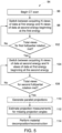
- FIG. 5 is a flow diagram of an embodiment of a method 94 for performing kVp switching for dual energy imaging.
- One or more steps of the method 94 may be performed by components of the CT imaging system 10 in FIG. 1 (e.g., processing circuitry and memory).
- the method 70 includes beginning a CT imaging scan (block 96).
- the imaging scan may utilize either two half-scans (e.g., when utilizing half-scan reconstruction) or two full-scans (e.g., two full rotations). In certain embodiments, the number of rotations may be different (e.g., 4 rotations, 6 rotations, etc.).
- the method 94 also includes switching between acquiring a first dataset of projection measurements at a first energy spectrum (e.g., low kVp) for a set number of views (e.g., n views in Equation 1, where n is greater than 1) at different projection angles during the first full or partial rotation and acquiring a second dataset of projection measurements at a second energy spectrum (e.g., high kVp) different from the first energy spectrum for the same set number of views at different projection angles during the first full or partial rotation (block 98).
- the method 94 determines if the total number of views (e.g., m views in Equation 1) for the first full or partial rotation are met (block 102).
- the method 94 repeats blocks 98, 100, and 102. It should be noted the first full or partial rotation begins and ends with acquiring projection measurements at the first energy spectrum. If the total number of view for the first full or partial rotation or met, the method 94 includes switching between acquiring the second dataset of projection measurements at the second energy spectrum (e.g., high kVp) for the same set number of views at different projection angles during the second full or partial rotation and acquiring the first dataset of projection measurements at the first energy spectrum (e.g., low kVp) for the same set number of views at different projection angles during the second full or partial rotation (block 104).
- the second energy spectrum e.g., high kVp
- the first energy spectrum e.g., low kVp
- the method 94 determines if the total number of views (e.g., m views in Equation 1) for the second full or partial rotation are met (block 102). If the total number of views for the second full or partial rotation are not met, the method 94 repeats blocks 104, 106, and 108. It should be noted the second full or partial rotation begins and ends with acquiring projection measurements at the second energy spectrum. After block 108, the amount of data acquired for both the first dataset and the second dataset are the same.
- the projection angles for the low kVp projection in the first half-scan or full-scan correspond to the projection angles for the high kVp projection in the second half-scan or full-scan.
- the projection angles for the high kVp projection in the first half-scan or full-scan correspond to the projection angles for the low kVp projection in the second half-scan or full-scan.
- the method 94 moves on.
- the method 94 includes generating additional data (e.g., parallel projections) to provide enough data for performing the disclosed techniques as described above (block 110).
- the method 94 also includes estimating projection measurements for missing projection angles not acquired during the imaging scan to supplement both the first dataset at the first energy and the second dataset at the second energy (block 112).
- the missing projection measurements supplied to the first dataset are derived from the second dataset.
- the missing projection measurements supplied to the second dataset are derived from the first dataset.
- the missing projection measurements are derived from the acquired projection measurements.
- the estimation of the projection measurements may occur as described in FIG. 3 .
- the method 94 further includes performing material decomposition and reconstruction to generate material images (e.g., material decomposition images or basis material images) (block 114).
- material images e.g., material decomposition images or basis material images
- projection space material decomposition is performed on the supplemented first and second datasets to generate basis material projections, followed by reconstructing material images from the basis material projections.
- image-space decomposition is performed on the supplemented first and second datasets to generate a reconstructed image at the first energy and a reconstructed image at the second energy, respectively, followed by image-domain material decomposition to generate material images.
- kVp switching technology for dual energy imaging on low-end CT imaging systems (which lack typical hardware solutions for dual energy imaging) that consist of cost effective hardware and only have lower kVp switching capability.
- the utilization of kVp switching technology for dual energy imaging applications may occur solely via a software update (i.e., without any hardware changes).
- low-end CT imaging systems may use dual energy for a vast number of clinical applications (e.g., kidney stones, lesion characterization, bone edema, etc.).
Landscapes
- Health & Medical Sciences (AREA)
- Life Sciences & Earth Sciences (AREA)
- Engineering & Computer Science (AREA)
- Medical Informatics (AREA)
- Physics & Mathematics (AREA)
- General Health & Medical Sciences (AREA)
- Pathology (AREA)
- Molecular Biology (AREA)
- Biomedical Technology (AREA)
- Biophysics (AREA)
- Nuclear Medicine, Radiotherapy & Molecular Imaging (AREA)
- Radiology & Medical Imaging (AREA)
- Veterinary Medicine (AREA)
- Animal Behavior & Ethology (AREA)
- Public Health (AREA)
- Surgery (AREA)
- High Energy & Nuclear Physics (AREA)
- Optics & Photonics (AREA)
- Heart & Thoracic Surgery (AREA)
- Theoretical Computer Science (AREA)
- General Physics & Mathematics (AREA)
- Pulmonology (AREA)
- Computer Vision & Pattern Recognition (AREA)
- Chemical & Material Sciences (AREA)
- Immunology (AREA)
- Biochemistry (AREA)
- Analytical Chemistry (AREA)
- Artificial Intelligence (AREA)
- Computational Linguistics (AREA)
- Data Mining & Analysis (AREA)
- Evolutionary Computation (AREA)
- Computing Systems (AREA)
- General Engineering & Computer Science (AREA)
- Mathematical Physics (AREA)
- Software Systems (AREA)
- Toxicology (AREA)
- Apparatus For Radiation Diagnosis (AREA)
Claims (15)
- Computer-implementiertes Verfahren zum Durchführen von kVp-Switching für die Dualenergiebildgebung und unter Verwendung einer Materialzerlegung, umfassend:Erfassen, während eines Bildgebungsscans, eines ersten Datensatzes von Projektionsmessungen an einem ersten Energiespektrum und eines zweiten Datensatzes von Projektionsmessungen an einem von dem ersten Energiespektrum unterschiedlichen zweiten Energiespektrum durch Umschalten zwischen dem Erfassen des ersten Datensatzes für eine festgesetzte Anzahl von aufeinanderfolgenden Ansichten in verschiedenen Projektionswinkeln an dem ersten Energiespektrum und dem Erfassen des zweiten Datensatzes für die festgesetzte Anzahl von aufeinanderfolgenden Ansichten in verschiedenen Projektionswinkeln an dem zweiten Energiespektrum, wobei die festgesetzte Anzahl von aufeinanderfolgenden Ansichten größer als eins ist; undgekennzeichnet durchErgänzen des ersten Datensatzes, der aus dem während des Bildgebungsscans erfassten zweiten Datensatz abgeleitet wird, und des während des Bildgebungsscans erfassten zweiten Datensatzes, der aus dem ersten Datensatz abgeleitet wird, mit geschätzten Projektionsmessungen, um fehlende Projektionsmessungen in verschiedenen Projektionswinkeln zu liefern, die während des Bildgebungsscans für den ersten Datensatz bzw. den zweiten Datensatz nicht erfasst werden.
- Computer-implementiertes Verfahren nach Anspruch 1, wobei die für sowohl den ersten Datensatz als auch den zweiten Datensatz erfassten Datenmengen gleich sind.
- Computer-implementiertes Verfahren nach Anspruch 1, wobei die geschätzten Projektionsmessungen an dem ersten Energiespektrum und dem zweiten Energiespektrum aus sowohl dem ersten Datensatz als auch dem zweiten Datensatz abgeleitet werden, und wobei die geschätzten Projektionsmessungen an dem ersten Energiespektrum in den Projektionswinkeln sowohl dem ersten Datensatz als auch dem zweiten Datensatz von Projektionsmessungen, aus denen sie abgeleitet sind, entsprechen, und die geschätzten Projektionsmessungen an dem zweiten Energiespektrum in den Projektionswinkeln sowohl dem ersten Datensatz als auch dem zweiten Datensatz von Projektionsmessungen, aus denen sie abgeleitet sind, entsprechen.
- Computer-implementiertes Verfahren nach Anspruch 1, umfassend:nach dem Ergänzen, getrenntes Erzeugen eines ersten rekonstruierten Bilds aus dem ersten Datensatz und eines zweiten rekonstruierten Bilds aus dem zweiten Datensatz; undDurchführen einer Materialzerlegung in der Bilddomäne an dem ersten rekonstruierten Bild und dem zweiten rekonstruierten Bild, um Basismaterial-Bilder zu erzeugen.
- Computer-implementiertes Verfahren nach Anspruch 1, umfassend:nach dem Ergänzen, Durchführen einer Materialzerlegung im Projektionsraum an dem ersten Datensatz und dem zweiten Datensatz, um Basismaterial-Projektionen zu erzeugen; undRekonstruieren von Basismaterial-Bildern aus den Basismaterial-Projektionen.
- Computer-implementiertes Verfahren nach Anspruch 1, wobei das Umschalten zwischen dem Erfassen des ersten Datensatzes für die festgesetzte Anzahl von aufeinanderfolgenden Ansichten in verschiedenen Projektionswinkeln an dem ersten Energiespektrum und dem Erfassen des zweiten Datensatzes für die festgesetzte Anzahl von aufeinanderfolgenden Ansichten in verschiedenen Projektionswinkeln an dem zweiten Energiespektrum wiederholt auftritt.
- Computer-implementiertes Verfahren nach Anspruch 6, wobei das Umschalten zwischen dem Erfassen des ersten Datensatzes für die festgesetzte Anzahl von aufeinanderfolgenden Ansichten in verschiedenen Projektionswinkeln an dem ersten Energiespektrum und dem Erfassen des zweiten Datensatzes für die festgesetzte Anzahl von aufeinanderfolgenden Ansichten in verschiedenen Projektionswinkeln an dem zweiten Energiespektrum wiederholt über eine erste vollständige Rotation (66), beginnend mit dem Erfassen des ersten Datensatzes, und dann wiederholt über eine zweite vollständige Rotation (68), beginnend mit dem Erfassen des zweiten Datensatzes, auftritt.
- Computer-implementiertes Verfahren nach Anspruch 7, wobei der während der ersten vollständigen Rotation (66) erfasste erste Datensatz im Projektionswinkel dem während der zweiten vollständigen Rotation (68) erfassten zweiten Datensatz entspricht.
- Computer-implementiertes Verfahren nach Anspruch 1, wobei die geschätzten Projektionsmessungen an dem ersten Energiespektrum und dem zweiten Energiespektrum unter Verwendung eines trainierten tiefen neuronalen Netzwerks abgeleitet werden.
- Prozessor-basiertes System zum Durchführen von kVp-Switching für die Dualenergiebildgebung und unter Verwendung einer Materialzerlegung, das Folgendes aufweist:einen Speicher (46), der prozessor-ausführbare Routinen kodiert; undeinen Prozessor (44), der konfiguriert ist, auf den Speicher (44) zuzugreifen und die prozessor-ausführbaren Routinen auszuführen, wobei die Routinen, wenn sie vom Prozessor (44) ausgeführt werden, bewirken, dass der Prozessor (44):während eines Bildgebungsscans einen ersten Datensatz von Projektionsmessungen an einem ersten Energiespektrum und einen zweiten Datensatz von Projektionsmessungen an einem von dem ersten Energiespektrum unterschiedlichen zweiten Energiespektrum durch Umschalten zwischen dem Erfassen des ersten Datensatzes für eine festgesetzte Anzahl von aufeinanderfolgenden Ansichten in verschiedenen Projektionswinkeln an dem ersten Energiespektrum und dem Erfassen des zweiten Datensatzes für die festgesetzte Anzahl von aufeinanderfolgenden Ansichten in verschiedenen Projektionswinkeln an dem zweiten Energiespektrum erfasst, wobei die festgesetzte Anzahl von aufeinanderfolgenden Ansichten größer als eins ist;und dadurch gekennzeichnet, dass die Routinen ferner bewirken, dass der Prozessor den ersten Datensatz, der aus dem während des Bildgebungsscans erfassten zweiten Datensatz abgeleitet wird, und den während des Bildgebungsscans erfassten zweiten Datensatz, der aus dem ersten Datensatz abgeleitet wird, mit geschätzten Projektionsmessungen ergänzt, um fehlende Projektionsmessungen in verschiedenen Projektionswinkeln zu liefern, die während des Bildgebungsscans für den ersten Datensatz bzw. den zweiten Datensatz nicht erfasst werden.
- Prozessor-basiertes System nach Anspruch 10, wobei die für sowohl den ersten Datensatz als auch den zweiten Datensatz erfassten Datenmengen gleich sind.
- Prozessor-basiertes System nach Anspruch 10, wobei die geschätzten Projektionsmessungen an dem ersten Energiespektrum und dem zweiten Energiespektrum aus sowohl dem ersten Datensatz als auch dem zweiten Datensatz abgeleitet werden, und wobei die geschätzten Projektionsmessungen an dem ersten Energiespektrum in den Projektionswinkeln sowohl dem ersten Datensatz als auch dem zweiten Datensatz von Projektionsmessungen, aus denen sie abgeleitet sind, entsprechen, und die geschätzten Projektionsmessungen an dem zweiten Energiespektrum in den Projektionswinkeln sowohl dem ersten Datensatz als auch dem zweiten Datensatz von Projektionsmessungen, aus denen sie abgeleitet sind, entsprechen.
- Prozessor-basiertes System nach Anspruch 10, wobei das Umschalten zwischen dem Erfassen des ersten Datensatzes für die festgesetzte Anzahl von aufeinanderfolgenden Ansichten in verschiedenen Projektionswinkeln an dem ersten Energiespektrum und dem Erfassen des zweiten Datensatzes für die festgesetzte Anzahl von aufeinanderfolgenden Ansichten in verschiedenen Projektionswinkeln an dem zweiten Energiespektrum wiederholt auftritt.
- Prozessor-basiertes System nach Anspruch 13, wobei das Umschalten zwischen dem Erfassen des ersten Datensatzes für die festgesetzte Anzahl von aufeinanderfolgenden Ansichten in verschiedenen Projektionswinkeln an dem ersten Energiespektrum und dem Erfassen des zweiten Datensatzes für die festgesetzte Anzahl von aufeinanderfolgenden Ansichten in verschiedenen Projektionswinkeln an dem zweiten Energiespektrum wiederholt über eine erste vollständige Rotation (66), beginnend mit dem Erfassen des ersten Datensatzes, und dann wiederholt über eine zweite vollständige Rotation (68), beginnend mit dem Erfassen des zweiten Datensatzes, auftritt.
- Prozessor-basiertes System nach Anspruch 10, wobei die geschätzten Projektionsmessungen an dem ersten Energiespektrum und dem zweiten Energiespektrum unter Verwendung eines trainierten tiefen neuronalen Netzwerks abgeleitet werden.
Applications Claiming Priority (1)
| Application Number | Priority Date | Filing Date | Title |
|---|---|---|---|
| US17/514,201 US11844639B2 (en) | 2021-10-29 | 2021-10-29 | System and method for utilizing dual energy imaging in a computed tomography imaging system |
Publications (2)
| Publication Number | Publication Date |
|---|---|
| EP4173568A1 EP4173568A1 (de) | 2023-05-03 |
| EP4173568B1 true EP4173568B1 (de) | 2024-10-09 |
Family
ID=83692992
Family Applications (1)
| Application Number | Title | Priority Date | Filing Date |
|---|---|---|---|
| EP22201479.7A Active EP4173568B1 (de) | 2021-10-29 | 2022-10-13 | System und verfahren zur verwendung von dualenergiebildgebung in einem computertomografiebildgebungssystem |
Country Status (4)
| Country | Link |
|---|---|
| US (1) | US11844639B2 (de) |
| EP (1) | EP4173568B1 (de) |
| JP (1) | JP7508518B2 (de) |
| CN (1) | CN116071445A (de) |
Family Cites Families (14)
| Publication number | Priority date | Publication date | Assignee | Title |
|---|---|---|---|---|
| JP5213016B2 (ja) | 2007-09-27 | 2013-06-19 | ジーイー・メディカル・システムズ・グローバル・テクノロジー・カンパニー・エルエルシー | X線ct装置 |
| JP5260036B2 (ja) | 2007-12-17 | 2013-08-14 | ジーイー・メディカル・システムズ・グローバル・テクノロジー・カンパニー・エルエルシー | X線ct装置 |
| JP5606667B2 (ja) | 2008-05-26 | 2014-10-15 | ジーイー・メディカル・システムズ・グローバル・テクノロジー・カンパニー・エルエルシー | X線ct装置 |
| JP5280172B2 (ja) | 2008-12-05 | 2013-09-04 | ジーイー・メディカル・システムズ・グローバル・テクノロジー・カンパニー・エルエルシー | X線ct装置 |
| US7970096B2 (en) | 2009-01-07 | 2011-06-28 | Analogic Corporation | Method of and system for low cost implementation of dual energy CT imaging |
| US7995702B2 (en) | 2009-08-25 | 2011-08-09 | General Electric Company | System and method of data interpolation in fast kVp switching dual energy CT |
| WO2012104740A1 (en) * | 2011-02-01 | 2012-08-09 | Koninklijke Philips Electronics N.V. | Method and system for dual energy ct image reconstruction |
| DE102012217555A1 (de) | 2012-09-27 | 2014-03-27 | Siemens Aktiengesellschaft | Verfahren und Computertomographie-System zur Ermittlung von Knochenmineraldichtewerten |
| US9274066B2 (en) | 2013-10-25 | 2016-03-01 | Kabushiki Kaisha Toshiba | Method for spectral CT local tomography |
| CN106530366B (zh) * | 2015-09-09 | 2019-04-16 | 清华大学 | 能谱ct图像重建方法及能谱ct成像系统 |
| US11039806B2 (en) | 2018-12-20 | 2021-06-22 | Canon Medical Systems Corporation | Apparatus and method that uses deep learning to correct computed tomography (CT) with sinogram completion of projection data |
| US11207041B2 (en) | 2019-07-08 | 2021-12-28 | Canon Medical Systems Corporation | X-ray CT system and medical processing apparatus |
| JP7353882B2 (ja) | 2019-09-12 | 2023-10-02 | キヤノンメディカルシステムズ株式会社 | X線ctシステム及び医用処理装置 |
| AU2022313161A1 (en) | 2021-07-22 | 2024-01-25 | Leo Cancer Care, Inc. | Scanner and method of image reconstruction |
-
2021
- 2021-10-29 US US17/514,201 patent/US11844639B2/en active Active
-
2022
- 2022-09-29 JP JP2022156587A patent/JP7508518B2/ja active Active
- 2022-10-13 EP EP22201479.7A patent/EP4173568B1/de active Active
- 2022-10-19 CN CN202211297031.9A patent/CN116071445A/zh active Pending
Also Published As
| Publication number | Publication date |
|---|---|
| JP7508518B2 (ja) | 2024-07-01 |
| CN116071445A (zh) | 2023-05-05 |
| US11844639B2 (en) | 2023-12-19 |
| US20230138814A1 (en) | 2023-05-04 |
| JP2023067768A (ja) | 2023-05-16 |
| EP4173568A1 (de) | 2023-05-03 |
Similar Documents
| Publication | Publication Date | Title |
|---|---|---|
| US9036886B2 (en) | System and method for correcting for metal artifacts using multi-energy computed tomography | |
| US8705822B2 (en) | Method for creating images indicating material decomposition in dual energy, dual source helical computed tomography | |
| JP5703014B2 (ja) | サンプリングレートを低減した2重エネルギー撮像 | |
| US7221728B2 (en) | Method and apparatus for correcting motion in image reconstruction | |
| US6879656B2 (en) | Method and apparatus for deriving motion information from projection data | |
| US7403588B2 (en) | Method for production of tomographic slice images of an examination object using at least two X-ray beams at offset angles, and a computed tomography scanner for carrying out this method | |
| US7995702B2 (en) | System and method of data interpolation in fast kVp switching dual energy CT | |
| WO2006123581A1 (ja) | 放射線撮影装置及び画像処理プログラム | |
| JP7091262B2 (ja) | コンピュータ断層撮影における空間分解能を向上させるためのシステムおよび方法 | |
| JP2014144274A (ja) | X線コンピュータ断層撮影装置及び医用画像処理装置 | |
| US6556697B1 (en) | Image reconstruction method | |
| US9943279B2 (en) | Methods and systems for task-based data generation and weighting for CT spectral imaging | |
| JP2023039438A (ja) | 画像生成装置、x線ct装置及び画像生成方法 | |
| US9129389B2 (en) | X-ray CT apparatus and image correction method | |
| US7359476B2 (en) | Radiation tomographic imaging apparatus and radiation tomographic imaging method, and image producing apparatus | |
| US20060120586A1 (en) | Method and system for extracting information about the cardiac cycle from CT projection data | |
| EP4173568B1 (de) | System und verfahren zur verwendung von dualenergiebildgebung in einem computertomografiebildgebungssystem | |
| JP2009112816A (ja) | コンピュータ断層撮影装置、再構成方法および記録媒体 | |
| JP5022690B2 (ja) | 放射線撮影装置 | |
| Heverhagen | Physics of computed tomography scanning | |
| JP7639094B2 (ja) | デュアルエネルギーctデータを補間するシステム及び方法 |
Legal Events
| Date | Code | Title | Description |
|---|---|---|---|
| PUAI | Public reference made under article 153(3) epc to a published international application that has entered the european phase |
Free format text: ORIGINAL CODE: 0009012 |
|
| STAA | Information on the status of an ep patent application or granted ep patent |
Free format text: STATUS: REQUEST FOR EXAMINATION WAS MADE |
|
| 17P | Request for examination filed |
Effective date: 20221013 |
|
| AK | Designated contracting states |
Kind code of ref document: A1 Designated state(s): AL AT BE BG CH CY CZ DE DK EE ES FI FR GB GR HR HU IE IS IT LI LT LU LV MC ME MK MT NL NO PL PT RO RS SE SI SK SM TR |
|
| P01 | Opt-out of the competence of the unified patent court (upc) registered |
Effective date: 20230528 |
|
| GRAP | Despatch of communication of intention to grant a patent |
Free format text: ORIGINAL CODE: EPIDOSNIGR1 |
|
| STAA | Information on the status of an ep patent application or granted ep patent |
Free format text: STATUS: GRANT OF PATENT IS INTENDED |
|
| RIC1 | Information provided on ipc code assigned before grant |
Ipc: A61B 6/00 20060101ALI20240415BHEP Ipc: G01N 23/046 20180101ALI20240415BHEP Ipc: A61B 6/40 20240101ALI20240415BHEP Ipc: A61B 6/42 20240101ALI20240415BHEP Ipc: A61B 6/03 20060101ALI20240415BHEP Ipc: G06T 11/00 20060101ALI20240415BHEP Ipc: G01N 23/087 20180101ALI20240415BHEP Ipc: A61B 5/00 20060101ALI20240415BHEP Ipc: A61B 6/02 20060101AFI20240415BHEP |
|
| INTG | Intention to grant announced |
Effective date: 20240503 |
|
| GRAS | Grant fee paid |
Free format text: ORIGINAL CODE: EPIDOSNIGR3 |
|
| GRAA | (expected) grant |
Free format text: ORIGINAL CODE: 0009210 |
|
| STAA | Information on the status of an ep patent application or granted ep patent |
Free format text: STATUS: THE PATENT HAS BEEN GRANTED |
|
| AK | Designated contracting states |
Kind code of ref document: B1 Designated state(s): AL AT BE BG CH CY CZ DE DK EE ES FI FR GB GR HR HU IE IS IT LI LT LU LV MC ME MK MT NL NO PL PT RO RS SE SI SK SM TR |
|
| REG | Reference to a national code |
Ref country code: CH Ref legal event code: EP |
|
| REG | Reference to a national code |
Ref country code: DE Ref legal event code: R096 Ref document number: 602022006656 Country of ref document: DE |
|
| REG | Reference to a national code |
Ref country code: IE Ref legal event code: FG4D |
|
| REG | Reference to a national code |
Ref country code: LT Ref legal event code: MG9D |
|
| REG | Reference to a national code |
Ref country code: NL Ref legal event code: MP Effective date: 20241009 |
|
| REG | Reference to a national code |
Ref country code: AT Ref legal event code: MK05 Ref document number: 1729665 Country of ref document: AT Kind code of ref document: T Effective date: 20241009 |
|
| PG25 | Lapsed in a contracting state [announced via postgrant information from national office to epo] |
Ref country code: NL Free format text: LAPSE BECAUSE OF FAILURE TO SUBMIT A TRANSLATION OF THE DESCRIPTION OR TO PAY THE FEE WITHIN THE PRESCRIBED TIME-LIMIT Effective date: 20241009 |
|
| PG25 | Lapsed in a contracting state [announced via postgrant information from national office to epo] |
Ref country code: NL Free format text: LAPSE BECAUSE OF FAILURE TO SUBMIT A TRANSLATION OF THE DESCRIPTION OR TO PAY THE FEE WITHIN THE PRESCRIBED TIME-LIMIT Effective date: 20241009 |
|
| PG25 | Lapsed in a contracting state [announced via postgrant information from national office to epo] |
Ref country code: IS Free format text: LAPSE BECAUSE OF FAILURE TO SUBMIT A TRANSLATION OF THE DESCRIPTION OR TO PAY THE FEE WITHIN THE PRESCRIBED TIME-LIMIT Effective date: 20250209 Ref country code: PT Free format text: LAPSE BECAUSE OF FAILURE TO SUBMIT A TRANSLATION OF THE DESCRIPTION OR TO PAY THE FEE WITHIN THE PRESCRIBED TIME-LIMIT Effective date: 20250210 Ref country code: HR Free format text: LAPSE BECAUSE OF FAILURE TO SUBMIT A TRANSLATION OF THE DESCRIPTION OR TO PAY THE FEE WITHIN THE PRESCRIBED TIME-LIMIT Effective date: 20241009 |
|
| PG25 | Lapsed in a contracting state [announced via postgrant information from national office to epo] |
Ref country code: FI Free format text: LAPSE BECAUSE OF FAILURE TO SUBMIT A TRANSLATION OF THE DESCRIPTION OR TO PAY THE FEE WITHIN THE PRESCRIBED TIME-LIMIT Effective date: 20241009 |
|
| PG25 | Lapsed in a contracting state [announced via postgrant information from national office to epo] |
Ref country code: BG Free format text: LAPSE BECAUSE OF FAILURE TO SUBMIT A TRANSLATION OF THE DESCRIPTION OR TO PAY THE FEE WITHIN THE PRESCRIBED TIME-LIMIT Effective date: 20241009 |
|
| PG25 | Lapsed in a contracting state [announced via postgrant information from national office to epo] |
Ref country code: ES Free format text: LAPSE BECAUSE OF FAILURE TO SUBMIT A TRANSLATION OF THE DESCRIPTION OR TO PAY THE FEE WITHIN THE PRESCRIBED TIME-LIMIT Effective date: 20241009 |
|
| PG25 | Lapsed in a contracting state [announced via postgrant information from national office to epo] |
Ref country code: NO Free format text: LAPSE BECAUSE OF FAILURE TO SUBMIT A TRANSLATION OF THE DESCRIPTION OR TO PAY THE FEE WITHIN THE PRESCRIBED TIME-LIMIT Effective date: 20250109 |
|
| PG25 | Lapsed in a contracting state [announced via postgrant information from national office to epo] |
Ref country code: GR Free format text: LAPSE BECAUSE OF FAILURE TO SUBMIT A TRANSLATION OF THE DESCRIPTION OR TO PAY THE FEE WITHIN THE PRESCRIBED TIME-LIMIT Effective date: 20250110 Ref country code: LV Free format text: LAPSE BECAUSE OF FAILURE TO SUBMIT A TRANSLATION OF THE DESCRIPTION OR TO PAY THE FEE WITHIN THE PRESCRIBED TIME-LIMIT Effective date: 20241009 Ref country code: AT Free format text: LAPSE BECAUSE OF FAILURE TO SUBMIT A TRANSLATION OF THE DESCRIPTION OR TO PAY THE FEE WITHIN THE PRESCRIBED TIME-LIMIT Effective date: 20241009 |
|
| PG25 | Lapsed in a contracting state [announced via postgrant information from national office to epo] |
Ref country code: PL Free format text: LAPSE BECAUSE OF FAILURE TO SUBMIT A TRANSLATION OF THE DESCRIPTION OR TO PAY THE FEE WITHIN THE PRESCRIBED TIME-LIMIT Effective date: 20241009 |
|
| PG25 | Lapsed in a contracting state [announced via postgrant information from national office to epo] |
Ref country code: RS Free format text: LAPSE BECAUSE OF FAILURE TO SUBMIT A TRANSLATION OF THE DESCRIPTION OR TO PAY THE FEE WITHIN THE PRESCRIBED TIME-LIMIT Effective date: 20250109 |
|
| PG25 | Lapsed in a contracting state [announced via postgrant information from national office to epo] |
Ref country code: SM Free format text: LAPSE BECAUSE OF FAILURE TO SUBMIT A TRANSLATION OF THE DESCRIPTION OR TO PAY THE FEE WITHIN THE PRESCRIBED TIME-LIMIT Effective date: 20241009 |
|
| PG25 | Lapsed in a contracting state [announced via postgrant information from national office to epo] |
Ref country code: MC Free format text: LAPSE BECAUSE OF FAILURE TO SUBMIT A TRANSLATION OF THE DESCRIPTION OR TO PAY THE FEE WITHIN THE PRESCRIBED TIME-LIMIT Effective date: 20241009 |
|
| PG25 | Lapsed in a contracting state [announced via postgrant information from national office to epo] |
Ref country code: DK Free format text: LAPSE BECAUSE OF FAILURE TO SUBMIT A TRANSLATION OF THE DESCRIPTION OR TO PAY THE FEE WITHIN THE PRESCRIBED TIME-LIMIT Effective date: 20241009 |
|
| REG | Reference to a national code |
Ref country code: DE Ref legal event code: R097 Ref document number: 602022006656 Country of ref document: DE |
|
| PG25 | Lapsed in a contracting state [announced via postgrant information from national office to epo] |
Ref country code: LU Free format text: LAPSE BECAUSE OF NON-PAYMENT OF DUE FEES Effective date: 20241013 Ref country code: BE Free format text: LAPSE BECAUSE OF NON-PAYMENT OF DUE FEES Effective date: 20241031 |
|
| PG25 | Lapsed in a contracting state [announced via postgrant information from national office to epo] |
Ref country code: EE Free format text: LAPSE BECAUSE OF FAILURE TO SUBMIT A TRANSLATION OF THE DESCRIPTION OR TO PAY THE FEE WITHIN THE PRESCRIBED TIME-LIMIT Effective date: 20241009 |
|
| PG25 | Lapsed in a contracting state [announced via postgrant information from national office to epo] |
Ref country code: RO Free format text: LAPSE BECAUSE OF FAILURE TO SUBMIT A TRANSLATION OF THE DESCRIPTION OR TO PAY THE FEE WITHIN THE PRESCRIBED TIME-LIMIT Effective date: 20241009 |
|
| PG25 | Lapsed in a contracting state [announced via postgrant information from national office to epo] |
Ref country code: SK Free format text: LAPSE BECAUSE OF FAILURE TO SUBMIT A TRANSLATION OF THE DESCRIPTION OR TO PAY THE FEE WITHIN THE PRESCRIBED TIME-LIMIT Effective date: 20241009 |
|
| PG25 | Lapsed in a contracting state [announced via postgrant information from national office to epo] |
Ref country code: CZ Free format text: LAPSE BECAUSE OF FAILURE TO SUBMIT A TRANSLATION OF THE DESCRIPTION OR TO PAY THE FEE WITHIN THE PRESCRIBED TIME-LIMIT Effective date: 20241009 |
|
| PG25 | Lapsed in a contracting state [announced via postgrant information from national office to epo] |
Ref country code: IT Free format text: LAPSE BECAUSE OF FAILURE TO SUBMIT A TRANSLATION OF THE DESCRIPTION OR TO PAY THE FEE WITHIN THE PRESCRIBED TIME-LIMIT Effective date: 20241009 |
|
| REG | Reference to a national code |
Ref country code: BE Ref legal event code: MM Effective date: 20241031 |
|
| PLBE | No opposition filed within time limit |
Free format text: ORIGINAL CODE: 0009261 |
|
| STAA | Information on the status of an ep patent application or granted ep patent |
Free format text: STATUS: NO OPPOSITION FILED WITHIN TIME LIMIT |
|
| PG25 | Lapsed in a contracting state [announced via postgrant information from national office to epo] |
Ref country code: SE Free format text: LAPSE BECAUSE OF FAILURE TO SUBMIT A TRANSLATION OF THE DESCRIPTION OR TO PAY THE FEE WITHIN THE PRESCRIBED TIME-LIMIT Effective date: 20241009 |
|
| 26N | No opposition filed |
Effective date: 20250710 |
|
| PG25 | Lapsed in a contracting state [announced via postgrant information from national office to epo] |
Ref country code: FR Free format text: LAPSE BECAUSE OF NON-PAYMENT OF DUE FEES Effective date: 20241209 |
|
| PG25 | Lapsed in a contracting state [announced via postgrant information from national office to epo] |
Ref country code: IE Free format text: LAPSE BECAUSE OF NON-PAYMENT OF DUE FEES Effective date: 20241013 |
|
| PGFP | Annual fee paid to national office [announced via postgrant information from national office to epo] |
Ref country code: DE Payment date: 20250923 Year of fee payment: 4 |
|
| PG25 | Lapsed in a contracting state [announced via postgrant information from national office to epo] |
Ref country code: CY Free format text: LAPSE BECAUSE OF FAILURE TO SUBMIT A TRANSLATION OF THE DESCRIPTION OR TO PAY THE FEE WITHIN THE PRESCRIBED TIME-LIMIT; INVALID AB INITIO Effective date: 20221013 |
|
| PG25 | Lapsed in a contracting state [announced via postgrant information from national office to epo] |
Ref country code: HU Free format text: LAPSE BECAUSE OF FAILURE TO SUBMIT A TRANSLATION OF THE DESCRIPTION OR TO PAY THE FEE WITHIN THE PRESCRIBED TIME-LIMIT; INVALID AB INITIO Effective date: 20221013 |