EP4173467A1 - Agricultural robot - Google Patents
Agricultural robot Download PDFInfo
- Publication number
- EP4173467A1 EP4173467A1 EP21829595.4A EP21829595A EP4173467A1 EP 4173467 A1 EP4173467 A1 EP 4173467A1 EP 21829595 A EP21829595 A EP 21829595A EP 4173467 A1 EP4173467 A1 EP 4173467A1
- Authority
- EP
- European Patent Office
- Prior art keywords
- crop
- estimator
- estimation
- agricultural robot
- data
- Prior art date
- Legal status (The legal status is an assumption and is not a legal conclusion. Google has not performed a legal analysis and makes no representation as to the accuracy of the status listed.)
- Pending
Links
Images













Classifications
-
- A—HUMAN NECESSITIES
- A01—AGRICULTURE; FORESTRY; ANIMAL HUSBANDRY; HUNTING; TRAPPING; FISHING
- A01D—HARVESTING; MOWING
- A01D46/00—Picking of fruits, vegetables, hops, or the like; Devices for shaking trees or shrubs
- A01D46/30—Robotic devices for individually picking crops
-
- G—PHYSICS
- G01—MEASURING; TESTING
- G01N—INVESTIGATING OR ANALYSING MATERIALS BY DETERMINING THEIR CHEMICAL OR PHYSICAL PROPERTIES
- G01N33/00—Investigating or analysing materials by specific methods not covered by groups G01N1/00 - G01N31/00
- G01N33/0098—Plants or trees
-
- G—PHYSICS
- G06—COMPUTING OR CALCULATING; COUNTING
- G06T—IMAGE DATA PROCESSING OR GENERATION, IN GENERAL
- G06T7/00—Image analysis
- G06T7/70—Determining position or orientation of objects or cameras
- G06T7/73—Determining position or orientation of objects or cameras using feature-based methods
-
- G—PHYSICS
- G06—COMPUTING OR CALCULATING; COUNTING
- G06V—IMAGE OR VIDEO RECOGNITION OR UNDERSTANDING
- G06V10/00—Arrangements for image or video recognition or understanding
- G06V10/20—Image preprocessing
- G06V10/255—Detecting or recognising potential candidate objects based on visual cues, e.g. shapes
-
- G—PHYSICS
- G06—COMPUTING OR CALCULATING; COUNTING
- G06V—IMAGE OR VIDEO RECOGNITION OR UNDERSTANDING
- G06V10/00—Arrangements for image or video recognition or understanding
- G06V10/40—Extraction of image or video features
- G06V10/42—Global feature extraction by analysis of the whole pattern, e.g. using frequency domain transformations or autocorrelation
- G06V10/422—Global feature extraction by analysis of the whole pattern, e.g. using frequency domain transformations or autocorrelation for representing the structure of the pattern or shape of an object therefor
-
- G—PHYSICS
- G06—COMPUTING OR CALCULATING; COUNTING
- G06V—IMAGE OR VIDEO RECOGNITION OR UNDERSTANDING
- G06V20/00—Scenes; Scene-specific elements
- G06V20/10—Terrestrial scenes
-
- G—PHYSICS
- G06—COMPUTING OR CALCULATING; COUNTING
- G06V—IMAGE OR VIDEO RECOGNITION OR UNDERSTANDING
- G06V20/00—Scenes; Scene-specific elements
- G06V20/60—Type of objects
- G06V20/68—Food, e.g. fruit or vegetables
-
- G—PHYSICS
- G06—COMPUTING OR CALCULATING; COUNTING
- G06T—IMAGE DATA PROCESSING OR GENERATION, IN GENERAL
- G06T2207/00—Indexing scheme for image analysis or image enhancement
- G06T2207/20—Special algorithmic details
- G06T2207/20084—Artificial neural networks [ANN]
-
- G—PHYSICS
- G06—COMPUTING OR CALCULATING; COUNTING
- G06T—IMAGE DATA PROCESSING OR GENERATION, IN GENERAL
- G06T2207/00—Indexing scheme for image analysis or image enhancement
- G06T2207/30—Subject of image; Context of image processing
- G06T2207/30004—Biomedical image processing
-
- G—PHYSICS
- G06—COMPUTING OR CALCULATING; COUNTING
- G06T—IMAGE DATA PROCESSING OR GENERATION, IN GENERAL
- G06T2207/00—Indexing scheme for image analysis or image enhancement
- G06T2207/30—Subject of image; Context of image processing
- G06T2207/30248—Vehicle exterior or interior
- G06T2207/30252—Vehicle exterior; Vicinity of vehicle
Definitions
- the present invention relates to an agricultural robot.
- Patent Literature 1 An agricultural robot disclosed in Patent Literature 1 is known.
- the agricultural robot disclosed in Patent Literature 1 includes a traveling body provided with a manipulator capable of harvesting crops.
- Patent Literature 1 Japanese Unexamined Patent Application Publication No. 2011-229406
- Crops such as watermelon, melon, and pumpkin are generally grown (planted) at various areas. It is necessary to appropriately obtain information about crops when doing work using an agricultural robot, but in reality it is difficult to appropriately obtain information about crops for various reasons.
- An object of the present invention is to provide an agricultural robot capable of easily estimating a crop from sensor data.
- Another object of the present invention is to provide an agricultural robot which makes it possible to easily know the posture of a crop.
- An agricultural robot includes a traveling body, a working unit to do work relating to a crop, the working unit being provided on the traveling body, an optical sensor provided on the traveling body, and a crop estimator to perform estimation of the crop based on sensor data obtained by the optical sensor, and the crop estimator includes a data extractor to designate the crop to be subjected to the estimation based on the sensor data and extract, as partial data, a part of the sensor data that corresponds to the designated crop, and an estimator to perform the estimation of the crop based on a surface condition of the crop obtained from the partial data extracted by the data extractor.
- the estimator is to, with respect to the crop represented in the partial data, perform the estimation of the crop based on a type of the crop and the surface condition of the crop.
- the estimator performs the estimation of the crop based on the type of the crop and a pattern on the crop as the surface condition of the crop.
- the estimator calculates, based on a result of the estimation of the crop, an outline of the crop included in the partial data.
- the estimator performs estimation of a type of the crop and, with respect to a surrounding area of the crop obtained in the partial data, estimates an obstacle which hides a surface of the crop having been subjected to the estimation.
- the working unit does work to move the obstacle estimated by the estimator away from the crop.
- the agricultural robot further includes a model generator to generate the surface condition model by subjecting a relationship between the crop and the surface condition of the crop to deep learning.
- An agricultural robot includes a traveling body, a working unit to do work relating to a crop, the working unit being provided on the traveling body, an optical sensor provided on the traveling body, and a crop estimator to perform estimation of the crop based on sensor data obtained by the optical sensor, and the crop estimator performs estimation of a posture of the crop based on a surface condition of the crop obtained from the sensor data.
- the crop estimator is to, with respect to the crop represented in the sensor data, perform the estimation of the posture of the crop based on one or more features of the crop and the surface condition of the crop.
- the crop estimator performs the estimation of the posture based on an orientation of a pattern on a surface of the crop represented in the sensor data.
- the crop estimator performs the estimation of the posture based on a length of a pattern on a surface of the crop represented in the sensor data.
- the crop estimator performs the estimation of the posture based on a positional relationship between one or more features of the crop and the pattern.
- the crop estimator is to, based on the sensor data, perform estimation of an outline of the crop and, with respect to a surrounding area of the crop, estimate is an obstacle which hides a surface of the crop having been subjected to the estimation.
- the working unit does work to move the obstacle estimated by the crop estimator away from the crop.
- the agricultural robot further includes a model generator to generate the surface condition model by subjecting a relationship between the crop and the surface condition of the crop to deep learning.
- the present invention makes it possible to easily estimate a crop from sensor data.
- the present invention also makes it possible to easily know the posture of a crop.
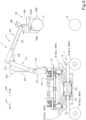
- FIGS. 1 and 2 illustrate an example of an agricultural robot 1.
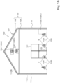
- the agricultural robot 1 does work (agricultural work) relating to crop(s) 2 grown (cultivated) in a facility such as a facility for protected horticulture (e.g., a house) or a plant factory as illustrated in FIGS. 16 to 19 .
- the agricultural robot 1 does work relating to, for example, heavy vegetables, fruits, and/or the like which are relatively heavy crops 2 such as watermelon, melon, and/or pumpkin.
- the following description discuses a facility with the use of, as an example, a facility for protected horticulture (protected horticulture facility).
- a facility 100 includes, as structures thereof, a house 101 and equipment 102 located inside the house 101.
- the house 101 includes a frame 110 and a covering 111.
- the frame 110 is, for example, a combination of various types of steel such as I-beam(s), H-beam(s), C-beam(s), square beam(s), and/or round beam(s) forming the framework of the facility 100, and includes a plurality of columns 110A and a plurality of connectors 110B. As illustrated in FIGS. 16 to 18 , the columns 110A extend upward from the ground or the like, are arranged at predetermined intervals in a widthwise direction X1, and are arranged at predetermined intervals in a longitudinal direction Y1.
- connectors 110B connect together the upper ends of columns 110A spaced apart from each other in the widthwise direction X1. Some of the connectors 110B connect together columns 110A spaced apart from each other in the lengthwise direction Y1.
- the covering 111 is made of a member transparent to light which at least allows passage of sunlight, such as synthetic resin and/or glass.
- the covering 111 covers the entire frame 110 on the outside of the frame 110.
- the covering 111 is located on the outside of the columns 110A and on the outside of the connectors 110B.
- the equipment 102 includes various types of equipment for use in cultivation of the crops 2 that are capable of adjusting the temperature, humidity, air flow, and/or the like in the house 101.
- the equipment 102 includes a ventilator 102A, a circulator 102B, a heat exchanger 102C, and/or the like.
- the ventilator 102A is located on an entrance 130 side of the house 101, and allows inside air to go out of the house 101 and allows outside air to enter the house 101.
- the circulator 102B is located inside the house 101 to allow air inside the house 101 to circulate in a predetermined direction.
- the heat exchanger 102C is capable of changing the temperature in the house 101, and is formed of, for example, a heat pump.
- the above-described pieces of equipment 102 are examples, and the equipment 102 may include a watering device, a light device, a sprayer, and/or the like. There is no limitation on the equipment 102.
- the agricultural robot 1 does various types of agricultural work relating to crop(s) 2 cultivated in cultivation area(s) 105 in the facility 100, such as, for example, harvesting the crops 2, spreading fertilizer, and/or spreading agricultural chemicals.
- the agricultural robot 1 is an autonomous robot.
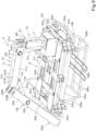
- FIGS. 1 to 8 illustrate the agricultural robot 1.
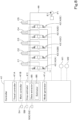
- FIG. 8 illustrates an assistance system for an agricultural robot.
- the direction indicated by arrow A1 in FIGS. 1 and 2 is referred to as a forward direction
- the direction indicated by arrow A2 in FIGS. 1 and 2 is referred to as a rearward direction
- the direction indicated by arrow A3 in FIG. 1 is referred to as a front-rear direction
- the direction indicated by arrow B 1 in FIG. 5 (direction to the near side in FIG. 1 ) is a leftward direction
- the direction indicated by arrow B2 in FIG. 5 (direction to the far side in FIG. 1 ) is a rightward direction
- a horizontal direction orthogonal to the front-rear direction A3 is referred to a machine body width direction (direction indicated by arrow B3 in FIG. 5 ).
- the agricultural robot 1 includes a traveling body 3 to travel autonomously.
- the traveling body 3 includes a machine body 6 and a traveling device 7 supporting the machine body 6 such that the machine body 6 is allowed to travel.
- the machine body 6 includes a main frame 6A and a prime mover frame 6B.
- the main frame 6A includes a pair of first frames 6Aa which are arranged with a space therebetween along the machine body width direction B3, and a pair of second frames 6Ab which are located below the respective first frames 6Aa and are arranged with a space therebetween.
- the first frames 6Aa and the second frames 6Ab are connected by a plurality of vertical frames 6Ac.
- the vertical frames 6Ac are provided between front portions of the left first frame 6Aa and the left second frame 6Ab, between front portions of the right first frame 6Aa and the right second frame 6Ab, between rear portions of the left first frame 6Aa and the left second frame 6Ab, and between rear portions of the right first frame 6Aa and the right second frame 6Ab.
- the left first frame 6Aa and the right first frame 6Aa are connected by first to fifth transverse frames 6Ad to 6Ah located between the first frames 6Aa.
- the first to fifth transverse frames 6Ad to 6Ah are arranged in parallel to each other along the front-rear direction A3 at intervals from the front ends of the first frames 6Aa to the rear ends of the first frames 6Aa.
- Front portions of the second frames 6Ab are connected by a sixth transverse frame 6Aj, and rear portions of the second frames 6Ab are connected by a seventh transverse frame 6Ak.
- the prime mover frame 6B is located below the main frame 6A.
- the prime mover frame 6B includes a front frame 6Ba, a rear frame 6Bb, a plurality of connector frames 6Bc, and a plurality of mount frames 6Bd.
- the front frame 6Ba has upper portions attached to the front portions of the left and right second frames 6Ab.
- the rear frame 6Bb has upper portions attached to the front portions of the left and right second frames 6Ab.
- the plurality of connector frames 6Bc connect together lower portions of the front frame 6Ba and the rear frame 6Bb.
- the plurality of mount frames 6Bd are fixed to a middle portion of each of the connector frames 6Bc in the front-rear direction A3.
- a prime mover (engine) E1 is attached to the mount frames 6Bd.
- a hydraulic pump P1 is attached to the prime mover E1.
- the hydraulic pump P1 is driven by the prime mover E1.
- the prime mover frame 6B is equipped with a hydraulic fluid tank (not illustrated) for storing hydraulic fluid to be discharged from the hydraulic pump P1.
- the main frame 6A (machine body 6) is equipped with a plurality of control valves (first to fourth control valves CV1 to CV4) to control the traveling device 7.
- the traveling device 7 is formed of a wheeled (four-wheel) traveling device including four wheels 8.
- the traveling device 7 includes a first wheel 8La (left front wheel) located at the front left of the machine body 6, a second wheel 8Ra (right front wheel) located at the front right of the machine body 6, a third wheel 8Lb (left rear wheel) located at the rear left of the machine body 6, and a fourth wheel 8Rb (right rear wheel) located at the rear right of the machine body 6.
- the traveling device 7 may be formed of a wheeled traveling device including at least three wheels 8.
- the traveling device 7 may be a crawler traveling device.
- the traveling device 7 includes wheel supports 9 which support the wheels 8.
- the number of the wheel supports 9 provided corresponds to the number of the wheels 8.
- the traveling device 7 includes a first wheel support 9La which supports the first wheel 8La, a second wheel support 9Ra which supports the second wheel 8Ra, a third wheel support 9Lb which supports the third wheel 8Lb, and a fourth wheel support 9Rb which supports the fourth wheel 8Rb.
- each of the wheel supports 9 includes a travel frame 10, a steering cylinder C1, a first lift cylinder C2, a second lift cylinder C3, and a travel motor M1.
- the travel frame 10 includes a main support 10A, a swing frame 10B, and a wheel frame 10C.
- the main support 10A is supported on the machine body 6 such that the main support 10A is rotatable about a vertical axis (axis extending along an up-and-down direction).
- the main support 10A is supported on a support bracket 11 fixed to the machine body 6 such that the main support 10A is rotatable about a first support shaft 12A having an axis extending along the up-and-down direction.
- the support bracket 11 which pivotally supports the first wheel support 9La is provided at the front left of the machine body 6
- the support bracket 11 which pivotally supports the second wheel support 9Ra is provided at the front right of the machine body 6
- the support bracket 11 which pivotally supports the third wheel support 9Lb is provided at the rear left of the machine body 6
- the support bracket 11 which pivotally supports the fourth wheel support 9Rb is provided at the rear right of the machine body 6.
- the swing frame 10B is supported on the main support 10A such that the swing frame 10B is swingable up and down. Specifically, the swing frame 10B has an upper portion supported on the main support 10A via a second support shaft 12B such that the swing frame 10B is pivotable about a sideways axis (axis extending in the machine body width direction B3).
- the swing frame 10B of each of the first and second wheel supports 9La and 9Ra has its upper front portion pivoted on a corresponding main support 10A
- the swing frame 10B of each of the third and fourth wheel supports 9Lb and 9Rb has its upper rear portion pivoted on a corresponding main support 10A.
- the wheel frame 10C is supported on the swing frame 10B such that the wheel frame 10C is swingable up and down. Specifically, the wheel frame 10C is supported on the swing frame 10B via a third support shaft 12C such that the wheel frame 10C is pivotable about a sideways axis.
- the wheel frame 10C of each of the first and second wheel supports 9La and 9Ra has its rear portion pivoted on a rear portion of a corresponding swing frame 10B
- the wheel frame 10C of each of the third and fourth wheel supports 9Lb and 9Rb has its front portion pivoted on a front portion of a corresponding swing frame 10B.
- the steering cylinder C1, the first lift cylinder C2, and the second lift cylinder C3 are each formed of a hydraulic cylinder.
- the steering cylinder C1 is located between the machine body 6 and the main support 10A. Specifically, the steering cylinder C1 has one end pivoted on a cylinder bracket 14A fixed to a middle portion of a corresponding first frame 6Aa in a front-rear direction A3, and has the opposite end pivoted on a cylinder bracket 14B fixed to the main support 10A. Extension or retraction of the steering cylinder C1 causes the travel frame 10 to swing about the first support shaft 12A, thus changing the orientation of a corresponding wheel 8 (corresponding one of the first to fourth wheels 8La to 8Rb) (steering the wheel 8). With regard to the traveling device 7 in the present embodiment, each of the wheels 8 can be steered independently.
- the first lift cylinder C2 has one end pivoted on the swing frame 10B and the opposite end pivoted on a first linkage mechanism 15A.
- the first linkage mechanism 15A includes a first link 15a and a second link 15b.
- the first link 15a has one end pivoted on the main support 10A
- the second link 15b has one end pivoted on the swing frame 10B.
- the first link 15a and the second link 15b each have the opposite end pivoted on the opposite end of the first lift cylinder C2. Extension or retraction of the first lift cylinder C2 causes the swing frame 10B to swing up or down about the second support shaft 12B.
- the second lift cylinder C3 has one end pivoted on a front portion of the swing frame 10B and the opposite end pivoted on a second linkage mechanism 15B.
- the second linkage mechanism 15B includes a first link 15c and a second link 15d.
- the first link 15c has one end pivoted on the swing frame 10B
- the second link 15d has one end pivoted on the wheel frame 10C.
- the first link 15c and the second link 15d each have the opposite end pivoted on the opposite end of the second lift cylinder C3. Extension or retraction of the second lift cylinder C3 causes the wheel frame 10C to swing up or down about the third support shaft 12C.
- the travel motor M1 is formed of a hydraulic motor. Such travel motors M1 are provided so as to correspond to the respective wheels 8. Specifically, the traveling device 7 includes a travel motor M1 to drive the first wheel 8La, a travel motor M1 to drive the second wheel 8Ra, a travel motor M1 to drive the third wheel 8Lb, and a travel motor M1 to drive the fourth wheel 8Rb. Each travel motor M1 is located inward of a corresponding wheel 8 in the machine body width direction B3 and is attached to a corresponding wheel frame 10C. Each travel motor M1 is driven by a hydraulic fluid discharged from the hydraulic pump P1 and is rotatable in forward and reverse directions. By changing the direction of rotation of the travel motor M1 between the forward direction and the reverse direction, it is possible to change the direction of rotation of a corresponding wheel 8 between the forward direction and the reverse direction.
- the second wheel support 9Ra, the third wheel support 9Lb, and the fourth wheel support 9Rb each include elements similar to those of the first wheel support 9La.
- the second wheel support 9Ra has a configuration laterally symmetrical to the first wheel support 9La.
- the third wheel support 9Lb is in the form obtained by a 180 degree rotation of the second wheel support 9Ra about a vertical central axis passing through the center of the machine body 6.
- the fourth wheel support 9Rb is in the form obtained by a 180 degree rotation of the first wheel support 9La about the central axis.
- Hydraulic actuator(s) attached to the first wheel support 9La is/are controlled by the first control valve CV1. Hydraulic actuator(s) attached to the second wheel support 9Ra is/are controlled by the second control valve CV2. Hydraulic actuator(s) attached to the third wheel support 9Lb is/are controlled by the third control valve CV3. Hydraulic actuator(s) attached to the fourth wheel support 9Rb is/are controlled by the fourth control valve CV4.
- first wheel 8La to the fourth wheel 8Rb can each independently be steered. Furthermore, the first wheel 8La to the fourth wheel 8Rb can each independently be raised and lowered.
- the traveling body 3 can be turned by steering the first wheel 8La to the fourth wheel 8Rb.
- the traveling body 3 can be caused to travel forward by causing the first wheel 8La to the fourth wheel 8Rb to rotate in the forward direction, and the traveling body 3 can be caused to travel rearward by causing the first wheel 8La to the fourth wheel 8Rb to rotate in the reverse direction.
- the traveling body 3 can be raised or lowered by raising or lowering the first wheel 8La to the fourth wheel 8Rb.
- the machine body 6 can be tilted forward or rearward by raising or lowering the first wheel 8La and the second wheel 8Ra relative to the third wheel 8Lb and the fourth wheel 8Rb or by raising or lowering the third wheel 8Lb and the fourth wheel 8Rb relative to the first wheel 8La and the second wheel 8Ra.
- the machine body 6 can be titled such that one of the opposite sides of the machine body 6 in the machine body width direction B3 is higher than the other by raising or lowering the first wheel 8La and the third wheel 8Lb relative to the second wheel 8Ra and the fourth wheel 8Rb or by raising or lowering the second wheel 8Ra and the fourth wheel 8Rb relative to the first wheel 8La and the third wheel 8Lb.
- the agricultural robot 1 includes a manipulator 4 (working unit) attached to the traveling body 3.
- the manipulator (working unit) 4 does work and, for example, in the present embodiment, is at least capable of harvesting a crop 2.
- the manipulator 4 includes a mount 16 detachably attached to the traveling body 3 (machine body 6), an arm 17 attached to the mount 16, and a robot hand 18 which is provided on the arm 17 and which is capable of holding the crop (target) 2.
- the mount 16 in the present embodiment is provided at the rear of the traveling body 3.
- the mount 16 may be provided at the front of the traveling body 3. That is, the mount 16 need only be provided at a location offset, in one direction, from the center of the traveling body 3 in the front-rear direction A3.
- the agricultural robot 1 does harvesting work as the traveling body 3 travels forward, and therefore the mount 16 is provided at a location offset in a direction opposite to the direction of travel.
- the mount 16 is in the form of a box and is detachably attached to the traveling body 3.
- the mount 16 has a rotating frame 21 extending upward.
- the rotating frame 21 can be caused to rotate about a rotation axis J1 by a rotary motor M2 provided inside the mount 16.
- the rotation of the rotating frame 21 causes the robot hand 18 to move (change in position) along a circumference centered on the rotation axis J1.
- the arm 17 is supported on the rotating frame 21 such that the arm 17 is swingable up and down, and is bendable at a lengthwise intermediate portion thereof.
- the arm 17 includes a main arm 29 and a sub-arm 30.
- the main arm 29 is pivoted on the rotating frame 21 such that the main arm 29 is swingable up and down, and is bendable.
- the main arm 29 includes a first arm assembly 31 pivoted on the rotating frame 21 such that the main arm 29 is swingable up and down, and a second arm assembly 32 swingably pivoted on the first arm assembly 31, and is capable of being bent by the swinging movement of the second arm assembly 32 relative to the first arm assembly 31.
- the first arm assembly 31 has a proximal portion 31a pivoted on an arm bracket 26. As illustrated in FIG. 3 , the first arm assembly 31 includes a first arm frame 31L and a second arm frame 31R. The first arm frame 31L and the second arm frame 31R are arranged along the machine body width direction B3 and are connected to each other by connector pipe(s) 31A and/or the like.
- An upper portion of the arm bracket 26 is inserted between proximal portions 31a of the first arm frame 31L and the second arm frame 31R, and the proximal portions 31a of the first arm frame 31L and the second arm frame 31R are supported on the arm bracket 26 via an arm pivot shaft 33A (referred to as a "first arm pivot shaft”) which has an axis extending along the machine body width direction B3 such that the proximal portions 31a of the first arm frame 31L and the second arm frame 31R are pivotable about the axis of the first arm pivot shaft 33A.
- an arm pivot shaft 33A referred to as a "first arm pivot shaft” which has an axis extending along the machine body width direction B3 such that the proximal portions 31a of the first arm frame 31L and the second arm frame 31R are pivotable about the axis of the first arm pivot shaft 33A.
- the first arm frame 31L and the second arm frame 31R are each formed of a hollow member.
- the length of the first arm assembly 31 is less than a dimension of the traveling body 3 (machine body 6) in the front-rear direction A3.
- the first arm assembly 31 includes a cylinder mount 31b which is in the proximal portion 31a and which is closer to a distal portion 31c than the first arm pivot shaft 33A is to the distal end portion 31c.
- a first arm cylinder (first hydraulic cylinder) C4 is provided to bridge the cylinder mount 31b and a cylinder mount portion 27a of a cylinder bracket 27.
- the first arm cylinder C4 is driven by hydraulic fluid discharged from the hydraulic pump P1 provided on the traveling body 3 to extend or retract.
- the extension or retraction of the first arm cylinder C4 causes the first arm assembly 31 to swing up or down.
- the upward or downward swinging movement of the first arm assembly 31 (arm 17) causes the robot hand 18 to be raised or lowered.
- the first arm cylinder C4 is provided with a first stroke sensor to detect strokes of the first arm cylinder C4.
- the first arm assembly 31 has a pivotally supporting member 31B fixed to the distal portion 31c thereof.
- the pivotally supporting member 31B includes a proximal portion 31Ba inserted between the first arm frame 31L and the second arm frame 31R, and is fixed to the first arm frame 31L and the second arm frame 31R.
- the pivotally supporting member 31B has a cylinder stay 34 attached to a lower surface of the proximal portion 31Ba.
- a distal portion 31Bb of the pivotally supporting member 31B projects forward from the first arm frame 31L and the second arm frame 31R.
- the length of the second arm assembly 32 is greater than the length of the first arm assembly 31.
- the second arm assembly 32 has a proximal portion 32a pivoted on the distal portion 31Bb of the pivotally supporting member 31B.
- the second arm assembly 32 includes a third arm frame 32L and a fourth arm frame 32R.
- the third arm frame 32L and the fourth arm frame 32R are arranged along the machine body width direction B3, and are connected to each other by a plurality of connector plates 35.
- the third arm frame 32L and the fourth arm frame 32R are each formed of a hollow member.
- the distal portion 31Bb of the pivotally supporting member 31B is inserted between proximal portions 32a of the third arm frame 32L and the fourth arm frame 32R.
- the third arm frame 32L and the fourth arm frame 32R (second arm assembly 32) are pivoted on the pivotally supporting member 31B via an arm pivot shaft (referred to as a "second arm pivot shaft") 33B having an axis extending along the machine body width direction B3.
- arm pivot shaft referred to as a "second arm pivot shaft” 33B having an axis extending along the machine body width direction B3.
- the second arm assembly 32 includes a cylinder mount 32c which is in the proximal portion 32a and which is closer to a distal portion 32b than the second arm pivot shaft 33B is to the distal portion 32b.
- a second arm cylinder (second hydraulic cylinder) C5 is provided to bridge the cylinder mount 32c and the cylinder stay 34.
- the second arm cylinder C5 is driven by hydraulic fluid discharged from the hydraulic pump P1 provided on the traveling body 3 to extend and retract.
- the extension or retraction of the second arm cylinder C5 causes the second arm assembly 32 to swing relative to the first arm assembly 31, causing the main arm 29 (arm 17) to be bent or stretched.
- the main arm 29 in a fully stretched state is in the form of a straight line, but the main arm 29 in a fully stretched state may be bent to some extent.
- the extension or retraction of the second arm cylinder C5 allows the robot hand 18 to move away from or toward the traveling body 3. Specifically, the extension of the second arm cylinder C5 allows the robot hand 18 to move in a direction away from the traveling body 3, and the retraction of the second arm cylinder C5 allows the robot hand 18 to move in a direction toward the traveling body 3.
- the second arm cylinder C5 is provided with a second stroke sensor S2 to detect strokes of the second arm cylinder C5.
- the sub-arm 30 is provided such that the sub-arm 30 can extend and retract relative to the second arm assembly 32. Therefore, the extension or retraction of the sub-arm 30 makes it possible to increase or reduce the length of the arm 17.
- the sub-arm 30 is formed of a square pipe in the form of a straight line.
- the sub-arm 30 is supported between distal portions (front portions) of the third arm frame 32L and the fourth arm frame 32R such that the sub-arm 30 is movable along a longitudinal direction.
- the sub-arm 30 is located between connector plates 35 facing each other, and can be fixed to the connector plates 35 with fixing member(s) such as bolt(s).
- the sub-arm 30 includes, on one side surface, protrusion(s) 30a which abut(s) the third arm frame 32L, and includes, on the opposite side surface, another protrusion(s) 30a which abut(s) the fourth arm frame 32R.
- the protrusions 30a make it possible to prevent or reduce the rattle of the sub-arm 30.
- the sub-arm 30 is, when in a fully retracted position, contained within the space between the third arm frame 32L and the fourth arm frame 32R. Note that the sub-arm 30 in the fully retracted position may project from the second arm assembly 32 to some extent.
- the sub-arm 30 has a hanger plate 37 fixed to a distal portion thereof.
- the robot hand 18 is pivoted on the hanger plate 37 and is hung on the hanger plate 37 (see FIG. 1 ). That is, the robot hand 18 is swingably attached to the distal portion of the sub-arm 30.
- the distal portion of the second arm assembly 32 is provided with a third stroke sensor to measure (detect) the degree of extension of the sub-arm 30 from the second arm assembly 32.
- the robot hand 18 includes a base member 18A and a plurality of holding nails 18B.
- a connecting piece 63 is provided at the upper surface side of the base member 18A.
- the connecting piece 63 is pivoted on the hanger plate 37. That is, the robot hand 18 is hung on the arm 17.
- the plurality of holding nails 18B are swingably attached to a lower surface side of the base member 18A.
- the robot hand 18 is capable of holding a crop 2 between the holding nails 18B (see FIG. 2 ) and is also capable of releasing the held crop 2, by the swinging movement of the holding nails 18B.
- the agricultural robot 1 includes optical sensors 5A and 5B.
- Each of the optical sensors 5A and 5B is a Charge Coupled Devices (CCD) camera equipped with a CCD image sensor, a Complementary Metal Oxide Semiconductor (CMOS) camera equipped with a CMOS image sensor, or an infrared camera.
- CCD Charge Coupled Devices
- CMOS Complementary Metal Oxide Semiconductor
- each of the optical sensors 5A and 5B is an imager (CCD camera, CMOS camera, or infrared camera).
- Each of the optical sensors 5A and 5B may be a laser sensor, i.e., Light Detection And Ranging (LiDAR).
- LiDAR Light Detection And Ranging
- a laser sensor is capable of constructing a three-dimensional map of a surrounding area of the traveling body 3 by emitting pulsed infrared light or the like several millions of times per second and measuring the time from the emission to the return of the infrared light.
- each of the optical sensors 5A and 5B is an imager (CCD camera, CMOS camera, or infrared camera).
- the optical sensor 5A is attached to the rotating frame 21. Specifically, the optical sensor 5A is attached to an upper portion of the arm bracket 26 via a supporting pillar 40. This does not imply any limitation, and the optical sensor 5A may be attached to the traveling body 3 and/or the like. A plurality of the optical sensors 5A may be provided at a plurality of locations. That is, the agricultural robot 1 may include a plurality of the optical sensors 5A.
- the optical sensor 5A is capable of capturing an image of the surrounding area of the traveling body 3, and acquires information about the surrounding area of the traveling body 3 by capturing an image.
- the optical sensor 5B is attached to a distal portion of the second arm assembly 32.
- the optical sensor 5B is capable of acquiring quality information by capturing an image of a crop 2.
- the quality information includes, for example, the size, shape, color, pattern (stripes on watermelon), damage, and/or the like of the crop 2.
- the agricultural robot 1 includes a tap sound sensor 50C.
- the tap sound sensor 50C acquires a tap sound that the crop 2 produces when hit (when tapped).
- the tap sound sensor 50C is provided on the robot hand 18 (base member 18A).
- the tap sound sensor 50C includes a tapping mechanism 51 and a sound recording mechanism 52.
- the tapping mechanism 51 includes a tapping member 51A movable toward and away from a crop 2 held with the holding nails 18B.
- the tapping member 51A is connected to an actuator 51B to cause the tapping member 51A to move in an axial direction.
- the actuator 51B is, for example, an electric actuator, and causes the tapping member 51A to move in the axial direction in accordance with a control signal to tap the crop 2 to cause the crop 2 to produce a tap sound.
- the sound recording mechanism 52 includes a microphone (highly directional microphone), and records (stores) a tap sound that the crop 2 produces when tapped with the tapping member S1A.
- the agricultural robot 1 includes a controller 41.
- the controller 41 is, for example, a microcomputer or the like including a central processing unit (CPU), an electrically erasable programmable read-only memory (EEPROM), and/or the like.
- the controller 41 has connected thereto the optical sensors 5A and 5B, the tap sound sensor 50C, the travel motors M1, and the rotary motor M2.
- the controller 41 has also connected thereto a plurality of control valves 42.
- the control valves 42 include first control valves 42A, second control valves 42B, third control valves 42C, a fourth control valve 42D, and a fifth control valve 42E.
- Each first control valve 42A controls a corresponding steering cylinder C1
- each second control valve 42B controls a corresponding first lift cylinder C2
- each third control valve 42C controls a corresponding second lift cylinder C3
- the fourth control valve 42D controls the first arm cylinder C4
- the fifth control valve 42E controls the second arm cylinder C5.
- the first control valves 42A, the second control valves 42B, the third control valves 42C, the fourth control valve 42D, and the fifth control valve 42E are each, for example, a solenoid valve actuated according to a control signal from the controller 41. More specifically, the first control valves 42A, the second control valves 42B, the third control valves 42C, the fourth control valve 42D, and the fifth control valve 42E are each a solenoid valve (three-way solenoid valve) whish achieves multi-position switching according to a control signal.
- the first control valves 42A Upon output of a control signal from the controller 41 to the first control valves 42A, the first control valves 42A are switched to a predetermined position according to the control signal.
- the second control valves 42B Upon output of a control signal from the controller 41 to the second control valves 42B, the second control valves 42B are switched to a predetermined position according to the control signal.
- the third control valves 42C are switched to a predetermined position according to the control signal.
- the fourth control valve 42D is switched to a predetermined position according to the control signal.
- the fifth control valve 42E is switched to a predetermined position according to the control signal.
- the first control valves 42A, the second control valves 42B, the third control valves 42C, the fourth control valve 42D, and the fifth control valve 42E have a fluid passage 46 connected thereto, and the fluid passage 46 has connected thereto the hydraulic pump P1 to deliver hydraulic fluid.
- each first control valve 42A switched between different positions, allows hydraulic fluid to be supplied selectively to either a bottom side chamber of a corresponding steering cylinder C1 or a rod side chamber of the corresponding steering cylinder C1, causing the steering cylinder C1 to extend or retract.
- Each second control valve 42B switched between different positions, allows hydraulic fluid to be supplied selectively to either a bottom side chamber of a corresponding first lift cylinder C2 or a rod side chamber of the corresponding first lift cylinder C2, causing the first lift cylinder C2 to extend or retract.
- Each third control valve 42C switched between different positions, allows hydraulic fluid to be supplied selectively to either a bottom side chamber of a corresponding second lift cylinder C3 or a rod side chamber of the corresponding second lift cylinder C3, causing the second lift cylinder C3 to extend or retract.
- the fourth control valve 42D switched between different positions, allows hydraulic fluid to be supplied selectively to either a bottom side chamber of the first arm cylinder C4 or a rod side chamber of the first arm cylinder C4, causing the first arm cylinder C4 to extend or retract.
- the fifth control valve 42E switched between different positions, allows hydraulic fluid to be supplied selectively to either a bottom side chamber of the second arm cylinder C5 or a rod side chamber of the second arm cylinder C5, causing the second arm cylinder C5 to extend or retract.
- the agricultural robot 1 includes a travel controller 41A.
- the travel controller 41A is electric/electronic circuit(s) provided in the controller 41, program(s) stored in the controller 41, and/or the like.
- the travel controller 41A controls the traveling device 7. Specifically, the travel controller 41A controls the steering cylinders C1 (first control valves 42A) and the travel motors M1. The travel controller 41A outputs a control signal to one or more of the first control valves 42A to cause corresponding one or more steering cylinders C1 to extend or retract to change the steering direction of the traveling device 7 (machine body 6). The travel controller 41A outputs a control signal to one or more of the travel motors M1 to change the rotation speed or the rotation direction of the travel motor(s) M1 to change the speed of the traveling device 7 (machine body 6) or the direction of travel of the traveling device 7 (machine body 6).
- the travel controller 41A may also control the raising/lowering, tilting, and/or the like of the machine body 6.
- the travel controller 41A outputs a control signal to one or more of the second control valves 42B to cause corresponding one or more of the first lift cylinders C2 to extend or retract to change the raised state, lowered state, and/or tilting state of the machine body 6.
- the travel controller 41A outputs a control signal to one or more of the third control valves 42C to cause corresponding one or more of the second lift cylinders C3 to extend or retract to change the raised state, lowered state, or tilting state of the machine body 6.
- the agricultural robot 1 is controlled by the travel controller 41A to autonomously travel in, for example, the facility 100.
- the agricultural robot 1 includes a work controller 41B.
- the work controller 41B is electric/electronic circuit(s) provided in the controller 41, program(s) stored in the controller 41, and/or the like.
- the work controller 41B controls the manipulator (working unit) 4. Specifically, the work controller 41B controls the first arm cylinder C4, the second arm cylinder C5, and the rotary motor M2. The work controller 41B outputs a control signal to the fourth control valve 42D to cause the first arm cylinder C4 to extend or retract to cause the first arm assembly 31 to swing. The work controller 41B outputs a control signal to the fifth control valve 42E to cause the second arm cylinder C5 to extract or retract to cause the second arm assembly 32 to swing. The work controller 41B outputs a control signal to the rotary motor M2 to change the rotation direction of the rotary motor M2 to cause the manipulator (working unit) 4 to rotate.
- the work controller 41B is capable of moving the robot hand 18 to any (desired) position. Specifically, it is possible to move the robot hand 18 to a target position by the movement of the robot hand 18 along a circumference centered on the rotation axis J1 caused by the rotation of the rotating frame 21, raising/lowering of the robot hand 18 caused by upward/downward swinging movement of the first arm assembly 31, and the movement of the robot hand 18 toward/away from the traveling body 3 caused by the swinging movement of the second arm assembly 32.
- the work controller 41B controls the actuator 51B (tapping member 51A).
- the work controller 41B performs the following control (tapping control): the work controller 41B outputs a control signal to the actuator 51B to actuate the actuator 51B to cause the tapping member 51A to tap the crop 2.
- the agricultural robot 1 includes a crop estimator 41I.
- the crop estimator 411 is electric/electronic circuit(s) provided in the controller 41, program(s) stored in the controller 41, and/or the like.
- the crop estimator 41I performs estimation of a crop 2 based on sensor data obtained by the optical sensor 5A or the optical sensor 5B.
- the sensor data is a captured image (image data).
- the optical sensor 5A or the optical sensor 5B is a laser sensor (LiDAR)
- the sensor data is scanned data including the distance and direction from the optical sensor 5A or the optical sensor 5B to the sensed target (object).
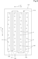
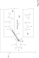
- the agricultural robot 1 when work such as harvesting is done by the agricultural robot 1, the agricultural robot 1 is caused to travel through passage(s) 106 between cultivation areas 105 in the facility 100. For example, during the work, the agricultural robot 1 is caused to travel along the cultivation area(s) 105 (passage(s) 106) from the work start point P11 to the work end point P12.
- the crop estimator 411 refers to sensor data (captured image, scanned data) H11 obtained by the optical sensor 5A or the optical sensor 5B to perform estimation of crop(s) 2.
- the crop estimator 41I includes a data extractor 85 and an estimator 86.
- the data extractor 85 designates a crop 2 which is to be subjected to the estimation based on the sensor data (captured image, scanned data) H11, and extracts, as partial data H13, the part of the sensor data (captured image, scanned data) H11 that corresponds to the designated crop and its surrounding area.
- the data extractor 85 refers to the sensor data H11 and designates a crop 2 which is to be subjected to estimation. As illustrated in FIG. 11 , the data extractor 85 determines whether or not the referenced sensor data H11 includes a portion of a crop 2. In the case where the sensor data H11 is a captured image, the data extractor 85 designates a crop 2 to be subjected to estimation in the captured image by subjecting the captured image to feature matching, pattern matching, and/or the like.
- the data extractor 85 compares feature(s) in a predetermined area of the captured image with feature(s) of a prepared image of a crop. If the feature(s) in the predetermined area of the captured image and the feature(s) of the prepared image match each other, the captured image is determined as including a crop 2 in the predetermined area. If the feature(s) in the predetermined area of the captured image and the feature(s) of the prepared image do not match each other, the captured image is determined as not including a crop 2 in the predetermined area.
- the data extractor 85 compares an image profile in a predetermined area of the captured image with a prepared reference profile indicative of the pattern on the surface of a crop 2, recesses/protrusions on the crop 2, and/or the like. If the reference profile and the image profile match each other, the captured image is determined as including a crop 2 and/or the like in the predetermined area. If the reference profile and the image profile do not match each other, the captured image is determined as not including a crop 2 in the predetermined area.
- the data extractor 85 determines whether or not an object imaged in the scanned data is a crop 2. In such a case, the data extractor 85 compares the profile of the object in a predetermined area in the data with a reference profile. If the reference profile and the profile in the data match each other, the scanned data is determined as including a crop 2. If the reference profile and the profile in the data do not match each other, the scanned data is determined as not including a crop 2.
- the data extractor 85 determines whether or not the sensor data H11 includes a crop 2 by subjecting the captured image to feature matching, pattern matching, and/or the like and/or by subjecting an imaged object to pattern matching and/or the like. If the data extractor 85 determines that the sensor data H11 includes a crop 2, the data extractor 85 designates the crop 2 determined as being included in the sensor data H11.
- the data extractor 85 extracts, as partial data H13, the designated crop 2 (referred to as "designated crop 2a") and its surrounding area from the sensor data H11.
- the data extractor 85 extracts, from a sensed subject (captured image obtained from the sensor data H11 or an object imaged in the sensor data H11), a portion (partial image) H16 corresponding to the designated crop 2 (designated crop 2a) and its surrounding area.
- the estimator 86 estimates, for example, the type of the designated crop 2a based on the surface condition of the designated crop 2a obtained from the partial data H13 (partial image H16) extracted by the data extractor 85.
- the estimator 86 uses a model (surface condition model), trained on types of crops 2 and surface conditions of the crops 2, to estimate the type of the designated crop 2 in the partial data H13.
- the surface condition model is a trained model built by inputting, into a computer, crop surface information in which surface conditions of many crops 2 and types of the crops 2 are associated with each other and causing the computer to perform deep learning using artificial intelligence (AI).
- AI artificial intelligence
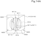
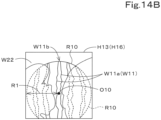
- the surface condition model estimates what type (of the crop 2) the designated crop 2a is, from the pattern on the designated crop 2a (which is a surface condition of the designated crop 2a) obtained from the partial data H13 (partial image H16). For example, as illustrated in FIGS. 14A to 14C , the surface condition model estimates the type of the designated crop 2 from a gap between lines W11 of the pattern, angles of the lines W11, how the lines W11 are connected, the shapes of the lines W11, and/or how the lines W11 are arranged on the surface of the designated crop 2a.
- the estimator 86 calculates an outline R10 of the designated crop 2 included in the partial data H13 (partial image H16) based on the result of the estimation of the type of the designated crop 2.
- the estimator 86 refers to a basic shape (a round shape, a rectangular shape, or an oval shape) of the outline R10 and a reference size L10 of a crop 2, based on the result of the estimation of the designated crop 2 (for example, based on the type of the crop 2).
- the estimator 86 extracts, for example, a straight line (stripe) W11a from lines (stripes) W 11 of the pattern on the designated crop 2 in the partial data H13 (partial image H16).
- the estimator 86 estimates that a line forming a circle or an oval passing through the opposite ends W11b of the line W11a is the outline R10 of the designated crop 2.
- the estimator 86 estimates that a point located at a distance corresponding to half the reference size from the one of the opposite ends W11b on the line W11a is a center O10 of the designated crop 2, that a distance corresponding to half the reference size from the center O10 is a radius R1 of the designated crop 2, and that a line forming a circle passing through the one of the opposite ends W11a and having the radius R1 is the outline R10 of the designated crop 2.
- the estimator 86 estimates the center O10 of the designated crop 2 from the pattern on the designated crop 2 in the frame of the extracted image, and estimates that a line forming a circle having the radius R1 is the outline R10 of the designated crop 2.
- FIGS. 14A to 14C are examples, and the surface condition model may estimate not only the type of crop but also the size of the crop from the pattern on the crop 2 and/or the like.
- the estimator 86 may, with respect to a surrounding area of the crop 2 obtained in the partial data H13 (partial image H16), estimate an obstacle W20 which hides the surface of the crop 2 having been subjected to the estimation.
- the estimator 86 extracts, from the surface of the crop 2, a portion W21 other than portions having been determined by the surface condition model as being the pattern on the surface of the crop 2, determines that an overlap between the portion W21 and an area defined by the outline R10 of the designated crop 2 is a portion of the obstacle W20, and extracts an entire outline W22 of the obstacle W20 by image processing and/or the like.
- the agricultural robot 1 does the work to move the obstacle W20 away from the crop 2 when, for example, harvesting the crop 2.
- the work controller 41B controls the manipulator (working unit) 4 (robot hand 18) to bring the distal end of the robot hand 18 closer to the obstacle W20, bring a part of the robot hand 18 into contact with the obstacle W20, and move the robot hand 18 with its distal portion in contact with the obstacle W20 to move the obstacle W20 away from the surface of the crop 2. That is, the robot hand 18 performs the action of moving the obstacle W20 away from the crop 2 when harvesting the crop 2.
- the agricultural robot 1 may include a model generator 411 to generate the surface condition model.
- the model generator 411 is electric/electronic circuit(s) provided in the controller 41, program(s) stored in the controller 41, and/or the like.
- the controller 41 acquires sensor data (data of the surface of the crop 2) obtained by sensing the surface of the crop 2 with the optical sensor 5A or the optical sensor 5B.
- the controller 41 acquires data of the surface of each crop 2 when harvesting it, and stores the acquired data in the form of a database.
- the model generator 41J builds a surface condition model by subjecting data of the surfaces of many crops 2 acquired by the controller 41 to deep learning. Note that the model generator 41J acquires, from the controller 41, data of the surface of each crop 2 when harvesting it even after the surface condition model is built, to continue reinforcement learning.
- An agricultural robot 1 includes a traveling body 3, a working unit 4 to do work relating to a crop 2, the working unit 4 being provided on the traveling body 3, an optical sensor 5A, 5B provided on the traveling body 3, and a crop estimator 411 to perform estimation of the crop 2 based on sensor data obtained by the optical sensor 5A, 5B, and the crop estimator 41I includes a data extractor 85 to designate the crop 2 to be subjected to the estimation based on the sensor data and extract, as partial data H13, a part of the sensor data that corresponds to the designated crop 2, and an estimator 86 to perform the estimation of the crop 2 based on a surface condition of the crop 2 obtained from the partial data H13 extracted by the data extractor 85.
- a crop 2 is designated from sensor data, data corresponding to the designated crop 2 is extracted as partial data H13, and then the estimation of the crop 2 is performed based on the surface condition in the extracted partial data H13, making it possible to perform the estimation of the crop 2 more efficiently and accurately. That is, it is possible to easily estimate a crop from sensor data.
- the estimator 86 is to, with respect to the crop 2 represented in the partial data H13, perform the estimation of the crop 2 based on a type of the crop 2 and the surface condition of the crop 2.
- the surface condition differs depending on the type of crop 2 and therefore, with the above configuration, since the estimation of the crop 2 is performed using type(s) of crop(s) 2 and surface condition(s), it is possible to estimate the crop 2 more accurately. In particular, even in cases where the surface of the crop 2 is covered and hidden by an obstacle W20 and only a portion of the surface condition of the crop 2 is exposed, it is still possible to easily estimate what the crop 2 is based on the relationship(s) between the type(s) of crop(s) 2 and surface condition(s).
- the estimator 86 performs the estimation of the crop 2 based on the type of the crop 2 and a pattern on the crop 2 as the surface condition of the crop 2. This makes it possible to easily estimate the crop 2 based on the fact that the pattern differs depending on the type of crop 2.
- the estimator 86 calculates, based on a result of the estimation of the crop 2, an outline W22 of the crop 2 included in the partial data H13.
- the result of the estimation of the crop 2 is the type of the crop 2
- the estimator 86 performs estimation of a type of the crop 2 and, with respect to a surrounding area of the crop 2 obtained in the partial data H13, estimates an obstacle W20 which hides a surface of the crop 2 having been subjected to the estimation. This makes it possible to easily estimate the outline of the obstacle W20, and possible to know the size of the obstacle W20 which covers the surface of the crop 2.
- the working unit 4 does work to move the obstacle W20 estimated by the estimator 86 away from the crop 2. This makes it possible, when work is done with respect to the crop 2 by the agricultural robot 1, to move the obstacle W20 which hinders the work away from the crop 2, making it possible to do the work efficiently. For example, in the case where the work is harvesting, it is possible to perform harvesting with the working unit 4 after removing the obstacle W20. Also in the case where the work is tapping the crop 2, acquiring a sound produced by tapping, and/or the like work, it is possible to do the work such as tapping the crop 2 after removing the obstacle W20.
- the agricultural robot 1 further includes a model generator 41J to generate a surface condition model by subjecting a relationship between the crop 2 and the surface condition of the crop 2 to deep learning. This makes it possible to easily prepare a model to estimate the relationship between a crop 2 and the surface condition of the crop 2.
- a controller 41 is such that the estimator 86 refers to partial data H13 (partial image H16) of a crop 2 identified by a surface condition model and, as illustrated in FIGS. 20A to 20C , estimates the posture of the crop 2 based on feature(s) W25 of the crop 2 and the surface condition (line(s) W11 of the pattern) of the crop 2. For example, as illustrated in FIGS. 20A , 20B , and 20C , the estimator 86 extracts, from the partial image H16, portion(s) corresponding to a stem end W25a and/or a navel W25b of the crop 2 as feature(s) W25.
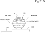
- the estimator 86 estimates the crop 2 as being in a posture Z1 (first posture) in which the navel W25b is located on the same side of the crop 2 as the ground of a cultivation area 105 and the stem end W25a faces up as illustrated in FIG. 21A .
- the estimator 86 estimates the crop 2 as being in a posture Z1 (first posture) in which the navel W25b faces toward the agricultural robot 1 and the stem end W25a faces in a direction away from the agricultural robot 1 as illustrated in FIG. 21B . That is, the crop 2 is in a second posture Z2 in which the crop 2 is laid such that the stem end W25a faces away from the agricultural robot 1.
- the estimator 86 estimates the crop 2 as being in a posture Z2 (second posture) in which the crop 2 is positioned along the agricultural robot 1 as illustrated in FIG. 21C . That is, the crop 2 is in a third posture Z3 in which, assuming that the stem end W25a is at the top of the crop 2, the crop 2 is laid in a direction parallel to the agricultural robot 1.
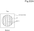
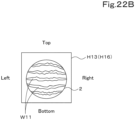
- the crop estimator 41I may estimate the posture based on the orientation of the pattern on the surface of the crop 2. If the direction of extension of line(s) W11 (longitudinal direction of continuous line(s)) of the pattern on the surface is an up-and-down direction (vertical direction) in the partial image H16 as illustrated in FIG. 22A , the crop estimator 41I (estimator 86) estimates the crop 2 as being in the first posture Z1. If the direction of extension of line(s) W11 is a sideways direction (horizontal direction) in the partial image H16 as illustrated in FIG. 22B , the crop estimator 411 (estimator 86) estimates the crop 2 as being in the third posture Z3.
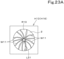
- the crop estimator 41I may estimate the posture based on the length of the pattern on the surface of a crop. If lengths L51 of lines W11 are substantially the same (within a predetermined range) and equal to or less than the standard length of a crop 2 (equal to or less than a reference) in the partial image H16 as illustrated in FIG. 23A , the crop estimator 41I (estimator 86) estimates the crop as being in the first posture Z1 or the second posture Z2.
- the crop estimator 41I estimates the crop 2 as being in the first posture Z1 when the image of the crop 2 is captured by the optical sensor 5A or 5B from above, and estimates the crop 2 as being in the second posture Z2 when the image of the crop 2 is captured by the optical sensor 5A or 5B from the side (from a passage 106).
- the crop estimator 41I estimates the crop 2 as being in the second posture Z2 or the third posture Z3. It is noted here that the crop estimator 41I (estimator 86) estimates the crop 2 as being in the second posture Z2 when the image of the crop 2 is captured by the optical sensor 5A or 5B from above, and estimates the crop 2 as being in the third posture Z3 when the image of the crop 2 is captured by the optical sensor 5A or 5B from the side (from a passage 106).
- the crop estimator 41I (estimator 86) may estimate the posture based on positional relationship(s) between feature(s) W25 of the crop 2 and the pattern on the crop 2.
- the crop estimator 411 estimates the crop 2 as being in the first posture Z1 but being slightly tilted to the far side. If the lengths L53 of the plurality of lines W11 are shorter on the near side of the stem end W25a and are shorter on the near side of the stem end W25a in the partial image H16 as illustrated in FIG. 24B , the crop estimator 411 (estimator 86) estimates the crop 2 as being in the first posture Z1 but being slightly tilted to the near side.
- the estimator 86 calculates an outline R10 of the designated crop 2 included in the partial data H13 (partial image H16) based on the result of the estimation of the type of the designated crop 2.
- the estimator 86 refers to a basic shape (a round shape, a rectangular shape, or an oval shape) of the outline R10 and a reference size L10 of a crop 2, based on the result of the estimation of the designated crop 2 (for example, based on the type of the crop 2).
- the estimator 86 extracts, for example, a straight line (stripe) W11a from lines (stripes) W11 of the pattern on the designated crop 2 in the partial data H13 (partial image H16).
- the estimator 86 estimates that a line forming a circle or an oval passing through the opposite ends W11b of the line W11a is the outline R10 of the designated crop 2.
- the estimator 86 estimates that a point located at a distance corresponding to half the reference size from the one of the opposite ends W11b on the line W11a is a center O10 of the designated crop 2, that a distance corresponding to half the reference size from the center O10 is a radius R1 of the designated crop 2, and that a line forming a circle passing through the one of the opposite ends W11a and having the radius R1 is the outline R10 of the designated crop 2.
- the estimator 86 estimates the center O10 of the designated crop 2 from the pattern on the designated crop 2 in the frame of the extracted image, and estimates that a line forming a circle having the radius R1 is the outline R10 of the designated crop 2.
- FIGS. 14A to 14C are examples, and the surface condition model may estimate not only the type of crop but also the size of the crop from the pattern on the crop 2 and/or the like.
- the estimator 86 may, with respect to a surrounding area of the crop 2 obtained in the partial data H13 (partial image H16), estimate an obstacle W20 which hides the surface of the crop 2 having been subjected to the estimation.
- the estimator 86 extracts, from the surface of the crop 2, a portion W21 other than portions having been determined by the surface condition model as being the pattern on the surface of the crop 2, determines that an overlap between the portion W21 and an area defined by the outline R10 of the designated crop 2 is a portion of the obstacle W20, and extracts an entire outline W22 of the obstacle W20 by image processing and/or the like.
- the agricultural robot 1 does the work to move the obstacle W20 away from the crop 2 when, for example, harvesting the crop 2.
- the work controller 41B controls the manipulator (working unit) 4 (robot hand 18) to bring the distal end of the robot hand 18 closer to the obstacle W20, bring a part of the robot hand 18 into contact with the obstacle W20, and move the robot hand 18 with its distal portion in contact with the obstacle W20 to move the obstacle W20 away from the surface of the crop 2. That is, the robot hand 18 performs the action of moving the obstacle W20 away from the crop 2 when harvesting the crop 2.
- the agricultural robot 1 may include a model generator 81I to generate the surface condition model.
- the model generator 81I is electric/electronic circuit(s) provided in the controller 41, program(s) stored in the controller 41, and/or the like.
- the controller 41 acquires sensor data (data of the surface of the crop 2) obtained by sensing the surface of the crop 2 with the optical sensor 5A or the optical sensor 5B.
- the controller 41 acquires data of the surface of each crop 2 when harvesting it, and stores the acquired data in the form of a database.
- the model generator 811 builds a surface condition model by subjecting data of the surfaces of many crops 2 acquired by the controller 41 to deep learning. Note that the model generator 811 acquires, from the controller 41, data of the surface of each crop 2 when harvesting it even after the surface condition model is built, to continue reinforcement learning.
- An agricultural robot 1 includes a traveling body 3, a working unit to do work relating to a crop 2, the working unit being provided on the traveling body 3, an optical sensor 5A, 5B provided on the traveling body 3, and a crop estimator 411 to perform estimation of the crop 2 based on sensor data obtained by the optical sensor 5A, 5B, and the crop estimator 41I performs estimation of a posture of the crop 2 based on a surface condition of the crop 2 obtained from the sensor data.
- the crop estimator 41I is to, with respect to the crop 2 represented in the sensor data, perform the estimation of the posture of the crop 2 based on one or more features of the crop 2 and the surface condition of the crop 2. This makes it possible to estimate the posture of the crop 2 based on the relationship between the feature(s) and the surface condition of the crop 2. For example, assuming that the stem end W25a and the navel W25b of the crop 2 are features, it is possible to know the posture of the crop 2 (for example, the crop 2 is pointing upward or titled sideways) based on the relationship between the directions in which the stem end W25a and the navel W25b are pointing and the shape(s) on the surface of the crop 2.
- the crop estimator 41I performs the estimation of the posture based on an orientation of a pattern on a surface of the crop 2 represented in the sensor data. This makes it possible to easily know the posture of the crop 2 based on, for example, whether the pattern on the surface of the crop 2 is oriented upward or downward.
- the crop estimator 411 performs the estimation of the posture based on a length of a pattern on a surface of the crop 2 represented in the sensor data. This makes it possible to easily know the posture of the crop 2 based on the length(s) of a particular pattern on the surface obtained by sensing the crop 2.
- the crop estimator 41I performs the estimation of the posture based on a positional relationship between one or more features of the crop 2 and a pattern. This makes it possible, for example, assuming that the stem end W25a and the navel W25b of the crop 2 are features, to easily know the posture of the crop 2 based on the positions of the stem end W25a, the navel W25b, and the pattern.
- the crop estimator 411 is to, based on the sensor data, perform estimation of an outline of the crop 2 and, with respect to a surrounding area of the crop 2, estimate an obstacle W20 which hides a surface of the crop 2 having been subjected to the estimation. This makes it possible to easily estimate the outline of the obstacle W20, and possible to know the size of the obstacle W20 which covers the surface of the crop 2.
- the working unit 4 does work to move the obstacle W20 estimated by the crop estimator 41I away from the crop 2. This makes it possible, when work is done with respect to the crop 2 by the agricultural robot 1, to move the obstacle W20 which hinders the work away from the crop 2, making it possible to do the work efficiently. For example, in the case where the work is harvesting, it is possible to perform harvesting with the working unit 4 after removing the obstacle W20. Also in the case where the work is tapping the crop 2, acquiring a sound produced by tapping, and/or the like work, it is possible to the work such as tapping the crop 2 after removing the obstacle W20.
- the agricultural robot further includes a model generator 81I to generate a surface condition model by subjecting a relationship between the crop 2 and the surface condition of the crop 2 to deep learning. This makes it possible to easily prepare a model to estimate the relationship between a crop 2 and the surface condition of the crop 2.
Landscapes
- Engineering & Computer Science (AREA)
- General Physics & Mathematics (AREA)
- Physics & Mathematics (AREA)
- Life Sciences & Earth Sciences (AREA)
- Theoretical Computer Science (AREA)
- Multimedia (AREA)
- Health & Medical Sciences (AREA)
- Chemical & Material Sciences (AREA)
- Analytical Chemistry (AREA)
- Botany (AREA)
- Wood Science & Technology (AREA)
- Environmental Sciences (AREA)
- Robotics (AREA)
- Food Science & Technology (AREA)
- Medicinal Chemistry (AREA)
- Biochemistry (AREA)
- General Health & Medical Sciences (AREA)
- Immunology (AREA)
- Pathology (AREA)
- Computer Vision & Pattern Recognition (AREA)
- Manipulator (AREA)
Abstract
Description
- The present invention relates to an agricultural robot.
- An agricultural robot disclosed in
Patent Literature 1 is known. - The agricultural robot disclosed in
Patent Literature 1 includes a traveling body provided with a manipulator capable of harvesting crops. - [Patent Literature 1]
Japanese Unexamined Patent Application Publication No. 2011-229406 - Crops such as watermelon, melon, and pumpkin are generally grown (planted) at various areas. It is necessary to appropriately obtain information about crops when doing work using an agricultural robot, but in reality it is difficult to appropriately obtain information about crops for various reasons.
- An object of the present invention is to provide an agricultural robot capable of easily estimating a crop from sensor data.
- Another object of the present invention is to provide an agricultural robot which makes it possible to easily know the posture of a crop.
- An agricultural robot according to a first aspect of the present invention includes a traveling body, a working unit to do work relating to a crop, the working unit being provided on the traveling body, an optical sensor provided on the traveling body, and a crop estimator to perform estimation of the crop based on sensor data obtained by the optical sensor, and the crop estimator includes a data extractor to designate the crop to be subjected to the estimation based on the sensor data and extract, as partial data, a part of the sensor data that corresponds to the designated crop, and an estimator to perform the estimation of the crop based on a surface condition of the crop obtained from the partial data extracted by the data extractor.
- The estimator is to, with respect to the crop represented in the partial data, perform the estimation of the crop based on a type of the crop and the surface condition of the crop.
- The estimator performs the estimation of the crop based on the type of the crop and a pattern on the crop as the surface condition of the crop.
- The estimator calculates, based on a result of the estimation of the crop, an outline of the crop included in the partial data.
- The estimator performs estimation of a type of the crop and, with respect to a surrounding area of the crop obtained in the partial data, estimates an obstacle which hides a surface of the crop having been subjected to the estimation.
- The working unit does work to move the obstacle estimated by the estimator away from the crop.
- The agricultural robot further includes a model generator to generate the surface condition model by subjecting a relationship between the crop and the surface condition of the crop to deep learning.
- An agricultural robot according to a second aspect of the present invention includes a traveling body, a working unit to do work relating to a crop, the working unit being provided on the traveling body, an optical sensor provided on the traveling body, and a crop estimator to perform estimation of the crop based on sensor data obtained by the optical sensor, and the crop estimator performs estimation of a posture of the crop based on a surface condition of the crop obtained from the sensor data.
- The crop estimator is to, with respect to the crop represented in the sensor data, perform the estimation of the posture of the crop based on one or more features of the crop and the surface condition of the crop.
- The crop estimator performs the estimation of the posture based on an orientation of a pattern on a surface of the crop represented in the sensor data.
- The crop estimator performs the estimation of the posture based on a length of a pattern on a surface of the crop represented in the sensor data.
- The crop estimator performs the estimation of the posture based on a positional relationship between one or more features of the crop and the pattern.
- The crop estimator is to, based on the sensor data, perform estimation of an outline of the crop and, with respect to a surrounding area of the crop, estimate is an obstacle which hides a surface of the crop having been subjected to the estimation.
- The working unit does work to move the obstacle estimated by the crop estimator away from the crop.
- The agricultural robot further includes a model generator to generate the surface condition model by subjecting a relationship between the crop and the surface condition of the crop to deep learning.
- The present invention makes it possible to easily estimate a crop from sensor data.
- The present invention also makes it possible to easily know the posture of a crop.
-
-
FIG. 1 is a side view of an agricultural robot according to a first embodiment of the present invention. -
FIG. 2 is a side view of the agricultural robot in a working posture according to the first embodiment. -
FIG. 3 is a perspective view of a machine body and a manipulator according to the first embodiment. -
FIG. 4 is a side view of the machine body and the manipulator according to the first embodiment. -
FIG. 5 is a plan view of a traveling device according to the first embodiment. -
FIG. 6 is a side view of a traveling device according to the first embodiment. -
FIG. 7 is an enlarged view of a portion of a robot hand according to the first embodiment. -
FIG. 8 is a general view of an assistance system for an agricultural robot according to the first embodiment. -
FIG. 9 illustrates a route along which the agricultural robot according to the first embodiment has traveled in a facility. -
FIG. 10 illustrates how the agricultural robot according to the first embodiment does work with respect to crops. -
FIG. 11 illustrates a relationship between sensor data H11 and partial data H13 according to the first embodiment. -
FIG. 12 illustrates an example of partial data H13 according to the first embodiment. -
FIG. 13 shows a relationship between a surface condition model and data according to the first embodiment. -
FIG. 14A illustrates a crop in partial image H16 in which the outline of the crop is partially exposed, in the first embodiment. -
FIG. 14B , which differs fromFIG. 14A , illustrates a crop in partial image H16 in which the outline of the crop is partially exposed, in the first embodiment. -
FIG. 14C illustrates partial image H16 in which the outline of the crop is hidden, in the first embodiment. -
FIG. 15 illustrates how work to move an obstacle away from a crop is done, in the first embodiment. -
FIG. 16 schematically illustrates the interior of a facility for protected horticulture according to the first embodiment. -
FIG. 17 is a plan view schematically illustrating the facility for protected horticulture according to the first embodiment. -
FIG. 18 is a perspective view of the interior of the facility for protected horticulture according to the first embodiment in which crops are in their initial stage of growth. -
FIG. 19 is a perspective view of the interior of the facility for protected horticulture according to the first embodiment in which crops are in their intermediate or late stage of growth. -
FIG. 20A is an illustration in which a stem end is extracted as a feature according to a second embodiment of the present invention. -
FIG. 20B is an illustration in which a navel is extracted as a feature according to the second embodiment. -
FIG. 20C is an illustration in which a stem end and a navel are extracted as features according to the second embodiment. -
FIG. 21A illustrates a first posture of a crop according to the second embodiment. -
FIG. 21B illustrates a second posture of the crop according to the second embodiment. -
FIG. 21C illustrates a third posture of the crop according to the second embodiment. -
FIG. 22A is an illustration in which lines of a pattern on a crop extend in an up-and-down direction (vertical direction) in the second embodiment. -
FIG. 22B is an illustration in which the lines of the pattern on the crop extend in a sideways direction (horizontal direction) in the second embodiment. -
FIG. 23A is an illustration in which the pattern on the crop has a length equal to or shorter than a standard length in the second embodiment. -
FIG. 23B is an illustration in which the pattern on the crop has a length longer than the standard length in the second embodiment. -
FIG. 24A illustrates a case in which lines on the near side of the stem end of a crop are longer than those on the far side of the stem end in the second embodiment. -
FIG. 24B illustrates a case in which lines on the near side of the stem end of the crop are shorter than those on the far side of the stem end in the second embodiment. - The following description discusses embodiments of the present invention with reference to drawings as appropriate.
-
FIGS. 1 and2 illustrate an example of anagricultural robot 1. Theagricultural robot 1 does work (agricultural work) relating to crop(s) 2 grown (cultivated) in a facility such as a facility for protected horticulture (e.g., a house) or a plant factory as illustrated inFIGS. 16 to 19 . Theagricultural robot 1 does work relating to, for example, heavy vegetables, fruits, and/or the like which are relativelyheavy crops 2 such as watermelon, melon, and/or pumpkin. - First, the following description discuses a facility with the use of, as an example, a facility for protected horticulture (protected horticulture facility).
- As illustrated in
FIGS. 16 to 19 , afacility 100 includes, as structures thereof, ahouse 101 andequipment 102 located inside thehouse 101. - The
house 101 includes aframe 110 and acovering 111. Theframe 110 is, for example, a combination of various types of steel such as I-beam(s), H-beam(s), C-beam(s), square beam(s), and/or round beam(s) forming the framework of thefacility 100, and includes a plurality ofcolumns 110A and a plurality ofconnectors 110B. As illustrated inFIGS. 16 to 18 , thecolumns 110A extend upward from the ground or the like, are arranged at predetermined intervals in a widthwise direction X1, and are arranged at predetermined intervals in a longitudinal direction Y1. - Some of the
connectors 110B connect together the upper ends ofcolumns 110A spaced apart from each other in the widthwise direction X1. Some of theconnectors 110B connect togethercolumns 110A spaced apart from each other in the lengthwise direction Y1. - The covering 111 is made of a member transparent to light which at least allows passage of sunlight, such as synthetic resin and/or glass. For example, the covering 111 covers the
entire frame 110 on the outside of theframe 110. In other words, the covering 111 is located on the outside of thecolumns 110A and on the outside of theconnectors 110B. - The
equipment 102 includes various types of equipment for use in cultivation of thecrops 2 that are capable of adjusting the temperature, humidity, air flow, and/or the like in thehouse 101. Specifically, theequipment 102 includes aventilator 102A, acirculator 102B, aheat exchanger 102C, and/or the like. As illustrated inFIGS. 16 and17 , theventilator 102A is located on anentrance 130 side of thehouse 101, and allows inside air to go out of thehouse 101 and allows outside air to enter thehouse 101. - The circulator 102B is located inside the
house 101 to allow air inside thehouse 101 to circulate in a predetermined direction. Theheat exchanger 102C is capable of changing the temperature in thehouse 101, and is formed of, for example, a heat pump. The above-described pieces ofequipment 102 are examples, and theequipment 102 may include a watering device, a light device, a sprayer, and/or the like. There is no limitation on theequipment 102. - The
agricultural robot 1 does various types of agricultural work relating to crop(s) 2 cultivated in cultivation area(s) 105 in thefacility 100, such as, for example, harvesting thecrops 2, spreading fertilizer, and/or spreading agricultural chemicals. Theagricultural robot 1 is an autonomous robot. -
FIGS. 1 to 8 illustrate theagricultural robot 1.FIG. 8 illustrates an assistance system for an agricultural robot. - The following description discusses the
agricultural robot 1 and the assistance system for an agricultural robot in detail. In the following description, the direction indicated by arrow A1 inFIGS. 1 and2 is referred to as a forward direction, the direction indicated by arrow A2 inFIGS. 1 and2 is referred to as a rearward direction, and the direction indicated by arrow A3 inFIG. 1 is referred to as a front-rear direction. Accordingly, the direction indicated byarrow B 1 inFIG. 5 (direction to the near side inFIG. 1 ) is a leftward direction, and the direction indicated by arrow B2 inFIG. 5 (direction to the far side inFIG. 1 ) is a rightward direction. A horizontal direction orthogonal to the front-rear direction A3 is referred to a machine body width direction (direction indicated by arrow B3 inFIG. 5 ). - As illustrated in
FIG. 1 , theagricultural robot 1 includes a travelingbody 3 to travel autonomously. The travelingbody 3 includes amachine body 6 and a travelingdevice 7 supporting themachine body 6 such that themachine body 6 is allowed to travel. - As illustrated in
FIGS. 3 and4 , themachine body 6 includes amain frame 6A and aprime mover frame 6B. Themain frame 6A includes a pair of first frames 6Aa which are arranged with a space therebetween along the machine body width direction B3, and a pair of second frames 6Ab which are located below the respective first frames 6Aa and are arranged with a space therebetween. The first frames 6Aa and the second frames 6Ab are connected by a plurality of vertical frames 6Ac. The vertical frames 6Ac are provided between front portions of the left first frame 6Aa and the left second frame 6Ab, between front portions of the right first frame 6Aa and the right second frame 6Ab, between rear portions of the left first frame 6Aa and the left second frame 6Ab, and between rear portions of the right first frame 6Aa and the right second frame 6Ab. - The left first frame 6Aa and the right first frame 6Aa are connected by first to fifth transverse frames 6Ad to 6Ah located between the first frames 6Aa. The first to fifth transverse frames 6Ad to 6Ah are arranged in parallel to each other along the front-rear direction A3 at intervals from the front ends of the first frames 6Aa to the rear ends of the first frames 6Aa.
- Front portions of the second frames 6Ab are connected by a sixth transverse frame 6Aj, and rear portions of the second frames 6Ab are connected by a seventh transverse frame 6Ak.
- The
prime mover frame 6B is located below themain frame 6A. Theprime mover frame 6B includes a front frame 6Ba, a rear frame 6Bb, a plurality of connector frames 6Bc, and a plurality of mount frames 6Bd. The front frame 6Ba has upper portions attached to the front portions of the left and right second frames 6Ab. The rear frame 6Bb has upper portions attached to the front portions of the left and right second frames 6Ab. The plurality of connector frames 6Bc connect together lower portions of the front frame 6Ba and the rear frame 6Bb. The plurality of mount frames 6Bd are fixed to a middle portion of each of the connector frames 6Bc in the front-rear direction A3. - As illustrated in
FIG. 4 , a prime mover (engine) E1 is attached to the mount frames 6Bd. A hydraulic pump P1 is attached to the prime mover E1. The hydraulic pump P1 is driven by the prime mover E1. Furthermore, theprime mover frame 6B is equipped with a hydraulic fluid tank (not illustrated) for storing hydraulic fluid to be discharged from the hydraulic pump P1. - As illustrated in
FIG. 5 , themain frame 6A (machine body 6) is equipped with a plurality of control valves (first to fourth control valves CV1 to CV4) to control the travelingdevice 7. - As illustrated in
FIGS. 1 ,2 , and5 , the travelingdevice 7 is formed of a wheeled (four-wheel) traveling device including fourwheels 8. Specifically, the travelingdevice 7 includes a first wheel 8La (left front wheel) located at the front left of themachine body 6, a second wheel 8Ra (right front wheel) located at the front right of themachine body 6, a third wheel 8Lb (left rear wheel) located at the rear left of themachine body 6, and a fourth wheel 8Rb (right rear wheel) located at the rear right of themachine body 6. Note that the travelingdevice 7 may be formed of a wheeled traveling device including at least threewheels 8. The travelingdevice 7 may be a crawler traveling device. - The traveling
device 7 includes wheel supports 9 which support thewheels 8. The number of the wheel supports 9 provided corresponds to the number of thewheels 8. Specifically, the travelingdevice 7 includes a first wheel support 9La which supports the first wheel 8La, a second wheel support 9Ra which supports the second wheel 8Ra, a third wheel support 9Lb which supports the third wheel 8Lb, and a fourth wheel support 9Rb which supports the fourth wheel 8Rb. - As illustrated in
FIGS. 5 and6 , each of the wheel supports 9 includes atravel frame 10, a steering cylinder C1, a first lift cylinder C2, a second lift cylinder C3, and a travel motor M1. - The
travel frame 10 includes amain support 10A, aswing frame 10B, and awheel frame 10C. Themain support 10A is supported on themachine body 6 such that themain support 10A is rotatable about a vertical axis (axis extending along an up-and-down direction). Specifically, themain support 10A is supported on asupport bracket 11 fixed to themachine body 6 such that themain support 10A is rotatable about afirst support shaft 12A having an axis extending along the up-and-down direction. - As illustrated in
FIG. 5 , thesupport bracket 11 which pivotally supports the first wheel support 9La is provided at the front left of themachine body 6, thesupport bracket 11 which pivotally supports the second wheel support 9Ra is provided at the front right of themachine body 6, thesupport bracket 11 which pivotally supports the third wheel support 9Lb is provided at the rear left of themachine body 6, and thesupport bracket 11 which pivotally supports the fourth wheel support 9Rb is provided at the rear right of themachine body 6. - The
swing frame 10B is supported on themain support 10A such that theswing frame 10B is swingable up and down. Specifically, theswing frame 10B has an upper portion supported on themain support 10A via asecond support shaft 12B such that theswing frame 10B is pivotable about a sideways axis (axis extending in the machine body width direction B3). - The
swing frame 10B of each of the first and second wheel supports 9La and 9Ra has its upper front portion pivoted on a correspondingmain support 10A, and theswing frame 10B of each of the third and fourth wheel supports 9Lb and 9Rb has its upper rear portion pivoted on a correspondingmain support 10A. - The
wheel frame 10C is supported on theswing frame 10B such that thewheel frame 10C is swingable up and down. Specifically, thewheel frame 10C is supported on theswing frame 10B via athird support shaft 12C such that thewheel frame 10C is pivotable about a sideways axis. - The
wheel frame 10C of each of the first and second wheel supports 9La and 9Ra has its rear portion pivoted on a rear portion of acorresponding swing frame 10B, and thewheel frame 10C of each of the third and fourth wheel supports 9Lb and 9Rb has its front portion pivoted on a front portion of acorresponding swing frame 10B. - The steering cylinder C1, the first lift cylinder C2, and the second lift cylinder C3 are each formed of a hydraulic cylinder.
- The steering cylinder C1 is located between the
machine body 6 and themain support 10A. Specifically, the steering cylinder C1 has one end pivoted on acylinder bracket 14A fixed to a middle portion of a corresponding first frame 6Aa in a front-rear direction A3, and has the opposite end pivoted on acylinder bracket 14B fixed to themain support 10A. Extension or retraction of the steering cylinder C1 causes thetravel frame 10 to swing about thefirst support shaft 12A, thus changing the orientation of a corresponding wheel 8 (corresponding one of the first to fourth wheels 8La to 8Rb) (steering the wheel 8). With regard to the travelingdevice 7 in the present embodiment, each of thewheels 8 can be steered independently. - The first lift cylinder C2 has one end pivoted on the
swing frame 10B and the opposite end pivoted on afirst linkage mechanism 15A. Thefirst linkage mechanism 15A includes afirst link 15a and asecond link 15b. Thefirst link 15a has one end pivoted on themain support 10A, and thesecond link 15b has one end pivoted on theswing frame 10B. Thefirst link 15a and thesecond link 15b each have the opposite end pivoted on the opposite end of the first lift cylinder C2. Extension or retraction of the first lift cylinder C2 causes theswing frame 10B to swing up or down about thesecond support shaft 12B. - The second lift cylinder C3 has one end pivoted on a front portion of the
swing frame 10B and the opposite end pivoted on asecond linkage mechanism 15B. Thesecond linkage mechanism 15B includes afirst link 15c and asecond link 15d. Thefirst link 15c has one end pivoted on theswing frame 10B, and thesecond link 15d has one end pivoted on thewheel frame 10C. Thefirst link 15c and thesecond link 15d each have the opposite end pivoted on the opposite end of the second lift cylinder C3. Extension or retraction of the second lift cylinder C3 causes thewheel frame 10C to swing up or down about thethird support shaft 12C. - The combination of upward or downward swinging movement of the
swing frame 10B caused by the first lift cylinder C2 and the upward or downward swinging movement of thewheel frame 10C caused by the second lift cylinder C3 allows a corresponding one of thewheels 8 to be raised or lowered in a parallel manner. - The travel motor M1 is formed of a hydraulic motor. Such travel motors M1 are provided so as to correspond to the
respective wheels 8. Specifically, the travelingdevice 7 includes a travel motor M1 to drive the first wheel 8La, a travel motor M1 to drive the second wheel 8Ra, a travel motor M1 to drive the third wheel 8Lb, and a travel motor M1 to drive the fourth wheel 8Rb. Each travel motor M1 is located inward of acorresponding wheel 8 in the machine body width direction B3 and is attached to acorresponding wheel frame 10C. Each travel motor M1 is driven by a hydraulic fluid discharged from the hydraulic pump P1 and is rotatable in forward and reverse directions. By changing the direction of rotation of the travel motor M1 between the forward direction and the reverse direction, it is possible to change the direction of rotation of acorresponding wheel 8 between the forward direction and the reverse direction. - The second wheel support 9Ra, the third wheel support 9Lb, and the fourth wheel support 9Rb each include elements similar to those of the first wheel support 9La. The second wheel support 9Ra has a configuration laterally symmetrical to the first wheel support 9La. The third wheel support 9Lb is in the form obtained by a 180 degree rotation of the second wheel support 9Ra about a vertical central axis passing through the center of the
machine body 6. The fourth wheel support 9Rb is in the form obtained by a 180 degree rotation of the first wheel support 9La about the central axis. - Hydraulic actuator(s) attached to the first wheel support 9La is/are controlled by the first control valve CV1. Hydraulic actuator(s) attached to the second wheel support 9Ra is/are controlled by the second control valve CV2. Hydraulic actuator(s) attached to the third wheel support 9Lb is/are controlled by the third control valve CV3. Hydraulic actuator(s) attached to the fourth wheel support 9Rb is/are controlled by the fourth control valve CV4.
- Thus, the first wheel 8La to the fourth wheel 8Rb can each independently be steered. Furthermore, the first wheel 8La to the fourth wheel 8Rb can each independently be raised and lowered.
- With regard to the traveling
device 7, the travelingbody 3 can be turned by steering the first wheel 8La to the fourth wheel 8Rb. The travelingbody 3 can be caused to travel forward by causing the first wheel 8La to the fourth wheel 8Rb to rotate in the forward direction, and the travelingbody 3 can be caused to travel rearward by causing the first wheel 8La to the fourth wheel 8Rb to rotate in the reverse direction. The travelingbody 3 can be raised or lowered by raising or lowering the first wheel 8La to the fourth wheel 8Rb. Themachine body 6 can be tilted forward or rearward by raising or lowering the first wheel 8La and the second wheel 8Ra relative to the third wheel 8Lb and the fourth wheel 8Rb or by raising or lowering the third wheel 8Lb and the fourth wheel 8Rb relative to the first wheel 8La and the second wheel 8Ra. Themachine body 6 can be titled such that one of the opposite sides of themachine body 6 in the machine body width direction B3 is higher than the other by raising or lowering the first wheel 8La and the third wheel 8Lb relative to the second wheel 8Ra and the fourth wheel 8Rb or by raising or lowering the second wheel 8Ra and the fourth wheel 8Rb relative to the first wheel 8La and the third wheel 8Lb. - The
agricultural robot 1 includes a manipulator 4 (working unit) attached to the travelingbody 3. The manipulator (working unit) 4 does work and, for example, in the present embodiment, is at least capable of harvesting acrop 2. - As illustrated in
FIGS. 1 and2 , themanipulator 4 includes amount 16 detachably attached to the traveling body 3 (machine body 6), anarm 17 attached to themount 16, and arobot hand 18 which is provided on thearm 17 and which is capable of holding the crop (target) 2. - As illustrated in
FIG. 1 , themount 16 in the present embodiment is provided at the rear of the travelingbody 3. Note that themount 16 may be provided at the front of the travelingbody 3. That is, themount 16 need only be provided at a location offset, in one direction, from the center of the travelingbody 3 in the front-rear direction A3. In the present embodiment, theagricultural robot 1 does harvesting work as the travelingbody 3 travels forward, and therefore themount 16 is provided at a location offset in a direction opposite to the direction of travel. Themount 16 is in the form of a box and is detachably attached to the travelingbody 3. - The
mount 16 has arotating frame 21 extending upward. The rotatingframe 21 can be caused to rotate about a rotation axis J1 by a rotary motor M2 provided inside themount 16. The rotation of therotating frame 21 causes therobot hand 18 to move (change in position) along a circumference centered on the rotation axis J1. - As illustrated in
FIGS. 3 and4 , thearm 17 is supported on therotating frame 21 such that thearm 17 is swingable up and down, and is bendable at a lengthwise intermediate portion thereof. Thearm 17 includes amain arm 29 and a sub-arm 30. - The
main arm 29 is pivoted on therotating frame 21 such that themain arm 29 is swingable up and down, and is bendable. Specifically, themain arm 29 includes afirst arm assembly 31 pivoted on therotating frame 21 such that themain arm 29 is swingable up and down, and asecond arm assembly 32 swingably pivoted on thefirst arm assembly 31, and is capable of being bent by the swinging movement of thesecond arm assembly 32 relative to thefirst arm assembly 31. - The
first arm assembly 31 has aproximal portion 31a pivoted on anarm bracket 26. As illustrated inFIG. 3 , thefirst arm assembly 31 includes afirst arm frame 31L and asecond arm frame 31R. Thefirst arm frame 31L and thesecond arm frame 31R are arranged along the machine body width direction B3 and are connected to each other by connector pipe(s) 31A and/or the like. An upper portion of thearm bracket 26 is inserted betweenproximal portions 31a of thefirst arm frame 31L and thesecond arm frame 31R, and theproximal portions 31a of thefirst arm frame 31L and thesecond arm frame 31R are supported on thearm bracket 26 via anarm pivot shaft 33A (referred to as a "first arm pivot shaft") which has an axis extending along the machine body width direction B3 such that theproximal portions 31a of thefirst arm frame 31L and thesecond arm frame 31R are pivotable about the axis of the firstarm pivot shaft 33A. - The
first arm frame 31L and thesecond arm frame 31R are each formed of a hollow member. The length of thefirst arm assembly 31 is less than a dimension of the traveling body 3 (machine body 6) in the front-rear direction A3. - As illustrated in
FIG. 4 , thefirst arm assembly 31 includes acylinder mount 31b which is in theproximal portion 31a and which is closer to adistal portion 31c than the firstarm pivot shaft 33A is to thedistal end portion 31c. A first arm cylinder (first hydraulic cylinder) C4 is provided to bridge thecylinder mount 31b and acylinder mount portion 27a of acylinder bracket 27. The first arm cylinder C4 is driven by hydraulic fluid discharged from the hydraulic pump P1 provided on the travelingbody 3 to extend or retract. The extension or retraction of the first arm cylinder C4 causes thefirst arm assembly 31 to swing up or down. The upward or downward swinging movement of the first arm assembly 31 (arm 17) causes therobot hand 18 to be raised or lowered. The first arm cylinder C4 is provided with a first stroke sensor to detect strokes of the first arm cylinder C4. - As illustrated in
FIG. 4 , thefirst arm assembly 31 has a pivotally supportingmember 31B fixed to thedistal portion 31c thereof. Specifically, the pivotally supportingmember 31B includes a proximal portion 31Ba inserted between thefirst arm frame 31L and thesecond arm frame 31R, and is fixed to thefirst arm frame 31L and thesecond arm frame 31R. The pivotally supportingmember 31B has acylinder stay 34 attached to a lower surface of the proximal portion 31Ba. A distal portion 31Bb of the pivotally supportingmember 31B projects forward from thefirst arm frame 31L and thesecond arm frame 31R. - As illustrated in
FIG. 3 , the length of thesecond arm assembly 32 is greater than the length of thefirst arm assembly 31. Thesecond arm assembly 32 has aproximal portion 32a pivoted on the distal portion 31Bb of the pivotally supportingmember 31B. Thesecond arm assembly 32 includes athird arm frame 32L and afourth arm frame 32R. Thethird arm frame 32L and thefourth arm frame 32R are arranged along the machine body width direction B3, and are connected to each other by a plurality ofconnector plates 35. Thethird arm frame 32L and thefourth arm frame 32R are each formed of a hollow member. The distal portion 31Bb of the pivotally supportingmember 31B is inserted betweenproximal portions 32a of thethird arm frame 32L and thefourth arm frame 32R. Thethird arm frame 32L and thefourth arm frame 32R (second arm assembly 32) are pivoted on the pivotally supportingmember 31B via an arm pivot shaft (referred to as a "second arm pivot shaft") 33B having an axis extending along the machine body width direction B3. - The
second arm assembly 32 includes acylinder mount 32c which is in theproximal portion 32a and which is closer to adistal portion 32b than the secondarm pivot shaft 33B is to thedistal portion 32b. A second arm cylinder (second hydraulic cylinder) C5 is provided to bridge thecylinder mount 32c and thecylinder stay 34. The second arm cylinder C5 is driven by hydraulic fluid discharged from the hydraulic pump P1 provided on the travelingbody 3 to extend and retract. The extension or retraction of the second arm cylinder C5 causes thesecond arm assembly 32 to swing relative to thefirst arm assembly 31, causing the main arm 29 (arm 17) to be bent or stretched. Note that, in the present embodiment, themain arm 29 in a fully stretched state is in the form of a straight line, but themain arm 29 in a fully stretched state may be bent to some extent. - Furthermore, the extension or retraction of the second arm cylinder C5 allows the
robot hand 18 to move away from or toward the travelingbody 3. Specifically, the extension of the second arm cylinder C5 allows therobot hand 18 to move in a direction away from the travelingbody 3, and the retraction of the second arm cylinder C5 allows therobot hand 18 to move in a direction toward the travelingbody 3. - As illustrated in
FIG. 4 , the second arm cylinder C5 is provided with a second stroke sensor S2 to detect strokes of the second arm cylinder C5. - The sub-arm 30 is provided such that the sub-arm 30 can extend and retract relative to the
second arm assembly 32. Therefore, the extension or retraction of the sub-arm 30 makes it possible to increase or reduce the length of thearm 17. The sub-arm 30 is formed of a square pipe in the form of a straight line. The sub-arm 30 is supported between distal portions (front portions) of thethird arm frame 32L and thefourth arm frame 32R such that the sub-arm 30 is movable along a longitudinal direction. Furthermore, the sub-arm 30 is located betweenconnector plates 35 facing each other, and can be fixed to theconnector plates 35 with fixing member(s) such as bolt(s). The sub-arm 30 includes, on one side surface, protrusion(s) 30a which abut(s) thethird arm frame 32L, and includes, on the opposite side surface, another protrusion(s) 30a which abut(s) thefourth arm frame 32R. Theprotrusions 30a make it possible to prevent or reduce the rattle of the sub-arm 30. - The sub-arm 30 is, when in a fully retracted position, contained within the space between the
third arm frame 32L and thefourth arm frame 32R. Note that the sub-arm 30 in the fully retracted position may project from thesecond arm assembly 32 to some extent. - As illustrated in
FIG. 4 , the sub-arm 30 has ahanger plate 37 fixed to a distal portion thereof. Therobot hand 18 is pivoted on thehanger plate 37 and is hung on the hanger plate 37 (seeFIG. 1 ). That is, therobot hand 18 is swingably attached to the distal portion of the sub-arm 30. The distal portion of thesecond arm assembly 32 is provided with a third stroke sensor to measure (detect) the degree of extension of the sub-arm 30 from thesecond arm assembly 32. - As illustrated in
FIGS. 1 and2 , therobot hand 18 includes abase member 18A and a plurality of holdingnails 18B. A connectingpiece 63 is provided at the upper surface side of thebase member 18A. The connectingpiece 63 is pivoted on thehanger plate 37. That is, therobot hand 18 is hung on thearm 17. The plurality of holdingnails 18B are swingably attached to a lower surface side of thebase member 18A. Therobot hand 18 is capable of holding acrop 2 between the holdingnails 18B (seeFIG. 2 ) and is also capable of releasing the heldcrop 2, by the swinging movement of the holdingnails 18B. - As illustrated in
FIGS. 1 and2 , theagricultural robot 1 includesoptical sensors optical sensors optical sensors optical sensors body 3 by emitting pulsed infrared light or the like several millions of times per second and measuring the time from the emission to the return of the infrared light. In the present embodiment, each of theoptical sensors - The
optical sensor 5A is attached to therotating frame 21. Specifically, theoptical sensor 5A is attached to an upper portion of thearm bracket 26 via a supportingpillar 40. This does not imply any limitation, and theoptical sensor 5A may be attached to the travelingbody 3 and/or the like. A plurality of theoptical sensors 5A may be provided at a plurality of locations. That is, theagricultural robot 1 may include a plurality of theoptical sensors 5A. Theoptical sensor 5A is capable of capturing an image of the surrounding area of the travelingbody 3, and acquires information about the surrounding area of the travelingbody 3 by capturing an image. - The
optical sensor 5B is attached to a distal portion of thesecond arm assembly 32. Theoptical sensor 5B is capable of acquiring quality information by capturing an image of acrop 2. The quality information includes, for example, the size, shape, color, pattern (stripes on watermelon), damage, and/or the like of thecrop 2. - As illustrated in
FIGS. 1 and2 , theagricultural robot 1 includes atap sound sensor 50C. Thetap sound sensor 50C acquires a tap sound that thecrop 2 produces when hit (when tapped). As illustrated inFIG. 7 , thetap sound sensor 50C is provided on the robot hand 18 (base member 18A). - The
tap sound sensor 50C includes atapping mechanism 51 and asound recording mechanism 52. Thetapping mechanism 51 includes a tappingmember 51A movable toward and away from acrop 2 held with the holdingnails 18B. The tappingmember 51A is connected to an actuator 51B to cause the tappingmember 51A to move in an axial direction. The actuator 51B is, for example, an electric actuator, and causes the tappingmember 51A to move in the axial direction in accordance with a control signal to tap thecrop 2 to cause thecrop 2 to produce a tap sound. Thesound recording mechanism 52 includes a microphone (highly directional microphone), and records (stores) a tap sound that thecrop 2 produces when tapped with the tapping member S1A. - As illustrated in
FIG. 8 , theagricultural robot 1 includes acontroller 41. Thecontroller 41 is, for example, a microcomputer or the like including a central processing unit (CPU), an electrically erasable programmable read-only memory (EEPROM), and/or the like. Thecontroller 41 has connected thereto theoptical sensors tap sound sensor 50C, the travel motors M1, and the rotary motor M2. Thecontroller 41 has also connected thereto a plurality ofcontrol valves 42. Thecontrol valves 42 includefirst control valves 42A,second control valves 42B,third control valves 42C, afourth control valve 42D, and afifth control valve 42E. - Each
first control valve 42A controls a corresponding steering cylinder C1, eachsecond control valve 42B controls a corresponding first lift cylinder C2, eachthird control valve 42C controls a corresponding second lift cylinder C3, thefourth control valve 42D controls the first arm cylinder C4, and thefifth control valve 42E controls the second arm cylinder C5. - The
first control valves 42A, thesecond control valves 42B, thethird control valves 42C, thefourth control valve 42D, and thefifth control valve 42E are each, for example, a solenoid valve actuated according to a control signal from thecontroller 41. More specifically, thefirst control valves 42A, thesecond control valves 42B, thethird control valves 42C, thefourth control valve 42D, and thefifth control valve 42E are each a solenoid valve (three-way solenoid valve) whish achieves multi-position switching according to a control signal. - Upon output of a control signal from the
controller 41 to thefirst control valves 42A, thefirst control valves 42A are switched to a predetermined position according to the control signal. Upon output of a control signal from thecontroller 41 to thesecond control valves 42B, thesecond control valves 42B are switched to a predetermined position according to the control signal. - Upon output of a control signal from the
controller 41 to thethird control valves 42C, thethird control valves 42C are switched to a predetermined position according to the control signal. Upon output of a control signal from thecontroller 41 to thefourth control valve 42D, thefourth control valve 42D is switched to a predetermined position according to the control signal. Upon output of a control signal from thecontroller 41 to thefifth control valve 42E, thefifth control valve 42E is switched to a predetermined position according to the control signal. - The
first control valves 42A, thesecond control valves 42B, thethird control valves 42C, thefourth control valve 42D, and thefifth control valve 42E have afluid passage 46 connected thereto, and thefluid passage 46 has connected thereto the hydraulic pump P1 to deliver hydraulic fluid. - With this, each
first control valve 42A, switched between different positions, allows hydraulic fluid to be supplied selectively to either a bottom side chamber of a corresponding steering cylinder C1 or a rod side chamber of the corresponding steering cylinder C1, causing the steering cylinder C1 to extend or retract. Eachsecond control valve 42B, switched between different positions, allows hydraulic fluid to be supplied selectively to either a bottom side chamber of a corresponding first lift cylinder C2 or a rod side chamber of the corresponding first lift cylinder C2, causing the first lift cylinder C2 to extend or retract. Eachthird control valve 42C, switched between different positions, allows hydraulic fluid to be supplied selectively to either a bottom side chamber of a corresponding second lift cylinder C3 or a rod side chamber of the corresponding second lift cylinder C3, causing the second lift cylinder C3 to extend or retract. - The
fourth control valve 42D, switched between different positions, allows hydraulic fluid to be supplied selectively to either a bottom side chamber of the first arm cylinder C4 or a rod side chamber of the first arm cylinder C4, causing the first arm cylinder C4 to extend or retract. Thefifth control valve 42E, switched between different positions, allows hydraulic fluid to be supplied selectively to either a bottom side chamber of the second arm cylinder C5 or a rod side chamber of the second arm cylinder C5, causing the second arm cylinder C5 to extend or retract. - The
agricultural robot 1 includes atravel controller 41A. Thetravel controller 41A is electric/electronic circuit(s) provided in thecontroller 41, program(s) stored in thecontroller 41, and/or the like. - The
travel controller 41A controls the travelingdevice 7. Specifically, thetravel controller 41A controls the steering cylinders C1 (first control valves 42A) and the travel motors M1. Thetravel controller 41A outputs a control signal to one or more of thefirst control valves 42A to cause corresponding one or more steering cylinders C1 to extend or retract to change the steering direction of the traveling device 7 (machine body 6). Thetravel controller 41A outputs a control signal to one or more of the travel motors M1 to change the rotation speed or the rotation direction of the travel motor(s) M1 to change the speed of the traveling device 7 (machine body 6) or the direction of travel of the traveling device 7 (machine body 6). - The
travel controller 41A may also control the raising/lowering, tilting, and/or the like of themachine body 6. For example, thetravel controller 41A outputs a control signal to one or more of thesecond control valves 42B to cause corresponding one or more of the first lift cylinders C2 to extend or retract to change the raised state, lowered state, and/or tilting state of themachine body 6. Thetravel controller 41A outputs a control signal to one or more of thethird control valves 42C to cause corresponding one or more of the second lift cylinders C3 to extend or retract to change the raised state, lowered state, or tilting state of themachine body 6. - As such, the
agricultural robot 1 is controlled by thetravel controller 41A to autonomously travel in, for example, thefacility 100. - The
agricultural robot 1 includes awork controller 41B. Thework controller 41B is electric/electronic circuit(s) provided in thecontroller 41, program(s) stored in thecontroller 41, and/or the like. - The
work controller 41B controls the manipulator (working unit) 4. Specifically, thework controller 41B controls the first arm cylinder C4, the second arm cylinder C5, and the rotary motor M2. Thework controller 41B outputs a control signal to thefourth control valve 42D to cause the first arm cylinder C4 to extend or retract to cause thefirst arm assembly 31 to swing. Thework controller 41B outputs a control signal to thefifth control valve 42E to cause the second arm cylinder C5 to extract or retract to cause thesecond arm assembly 32 to swing. Thework controller 41B outputs a control signal to the rotary motor M2 to change the rotation direction of the rotary motor M2 to cause the manipulator (working unit) 4 to rotate. - As has been discussed, the
work controller 41B is capable of moving therobot hand 18 to any (desired) position. Specifically, it is possible to move therobot hand 18 to a target position by the movement of therobot hand 18 along a circumference centered on the rotation axis J1 caused by the rotation of therotating frame 21, raising/lowering of therobot hand 18 caused by upward/downward swinging movement of thefirst arm assembly 31, and the movement of therobot hand 18 toward/away from the travelingbody 3 caused by the swinging movement of thesecond arm assembly 32. - The
work controller 41B controls the actuator 51B (tappingmember 51A). For example, thework controller 41B performs the following control (tapping control): thework controller 41B outputs a control signal to the actuator 51B to actuate the actuator 51B to cause the tappingmember 51A to tap thecrop 2. - As illustrated in
FIG. 8 , theagricultural robot 1 includes acrop estimator 41I. The crop estimator 411 is electric/electronic circuit(s) provided in thecontroller 41, program(s) stored in thecontroller 41, and/or the like. - The
crop estimator 41I performs estimation of acrop 2 based on sensor data obtained by theoptical sensor 5A or theoptical sensor 5B. When theoptical sensor 5A or theoptical sensor 5B is an imager, the sensor data is a captured image (image data). When theoptical sensor 5A or theoptical sensor 5B is a laser sensor (LiDAR), the sensor data is scanned data including the distance and direction from theoptical sensor 5A or theoptical sensor 5B to the sensed target (object). - As illustrated in
FIG. 9 , when work such as harvesting is done by theagricultural robot 1, theagricultural robot 1 is caused to travel through passage(s) 106 betweencultivation areas 105 in thefacility 100. For example, during the work, theagricultural robot 1 is caused to travel along the cultivation area(s) 105 (passage(s) 106) from the work start point P11 to the work end point P12. - As illustrated in
FIG. 11 , during travel of theagricultural robot 1, the crop estimator 411 refers to sensor data (captured image, scanned data) H11 obtained by theoptical sensor 5A or theoptical sensor 5B to perform estimation of crop(s) 2. - The following description discusses the
crop estimator 41I in detail. - As illustrated in
FIG. 8 , thecrop estimator 41I includes adata extractor 85 and anestimator 86. Thedata extractor 85 designates acrop 2 which is to be subjected to the estimation based on the sensor data (captured image, scanned data) H11, and extracts, as partial data H13, the part of the sensor data (captured image, scanned data) H11 that corresponds to the designated crop and its surrounding area. - Specifically, first, as illustrated in
FIG. 10 , when theagricultural robot 1 is caused to travel autonomously in the direction of travel in order to do work with respect tocrops 2 under cultivation in thecultivation area 105, thedata extractor 85 refers to the sensor data H11 and designates acrop 2 which is to be subjected to estimation. As illustrated inFIG. 11 , thedata extractor 85 determines whether or not the referenced sensor data H11 includes a portion of acrop 2. In the case where the sensor data H11 is a captured image, thedata extractor 85 designates acrop 2 to be subjected to estimation in the captured image by subjecting the captured image to feature matching, pattern matching, and/or the like. - For example, the
data extractor 85 compares feature(s) in a predetermined area of the captured image with feature(s) of a prepared image of a crop. If the feature(s) in the predetermined area of the captured image and the feature(s) of the prepared image match each other, the captured image is determined as including acrop 2 in the predetermined area. If the feature(s) in the predetermined area of the captured image and the feature(s) of the prepared image do not match each other, the captured image is determined as not including acrop 2 in the predetermined area. - Alternatively, the
data extractor 85 compares an image profile in a predetermined area of the captured image with a prepared reference profile indicative of the pattern on the surface of acrop 2, recesses/protrusions on thecrop 2, and/or the like. If the reference profile and the image profile match each other, the captured image is determined as including acrop 2 and/or the like in the predetermined area. If the reference profile and the image profile do not match each other, the captured image is determined as not including acrop 2 in the predetermined area. - Note that, when the sensor data H11 is scanned data, the
data extractor 85 determines whether or not an object imaged in the scanned data is acrop 2. In such a case, thedata extractor 85 compares the profile of the object in a predetermined area in the data with a reference profile. If the reference profile and the profile in the data match each other, the scanned data is determined as including acrop 2. If the reference profile and the profile in the data do not match each other, the scanned data is determined as not including acrop 2. - That is, the
data extractor 85 determines whether or not the sensor data H11 includes acrop 2 by subjecting the captured image to feature matching, pattern matching, and/or the like and/or by subjecting an imaged object to pattern matching and/or the like. If thedata extractor 85 determines that the sensor data H11 includes acrop 2, thedata extractor 85 designates thecrop 2 determined as being included in the sensor data H11. - As illustrated in
FIGS. 11 and12 , thedata extractor 85 extracts, as partial data H13, the designated crop 2 (referred to as "designatedcrop 2a") and its surrounding area from the sensor data H11. In other words, thedata extractor 85 extracts, from a sensed subject (captured image obtained from the sensor data H11 or an object imaged in the sensor data H11), a portion (partial image) H16 corresponding to the designated crop 2 (designatedcrop 2a) and its surrounding area. - Next, the
estimator 86 estimates, for example, the type of the designatedcrop 2a based on the surface condition of the designatedcrop 2a obtained from the partial data H13 (partial image H16) extracted by thedata extractor 85. - Specifically, as shown in
FIG. 13 , theestimator 86 uses a model (surface condition model), trained on types ofcrops 2 and surface conditions of thecrops 2, to estimate the type of the designatedcrop 2 in the partial data H13. The surface condition model is a trained model built by inputting, into a computer, crop surface information in which surface conditions ofmany crops 2 and types of thecrops 2 are associated with each other and causing the computer to perform deep learning using artificial intelligence (AI). - The surface condition model estimates what type (of the crop 2) the designated
crop 2a is, from the pattern on the designatedcrop 2a (which is a surface condition of the designatedcrop 2a) obtained from the partial data H13 (partial image H16). For example, as illustrated inFIGS. 14A to 14C , the surface condition model estimates the type of the designatedcrop 2 from a gap between lines W11 of the pattern, angles of the lines W11, how the lines W11 are connected, the shapes of the lines W11, and/or how the lines W11 are arranged on the surface of the designatedcrop 2a. - The
estimator 86 calculates an outline R10 of the designatedcrop 2 included in the partial data H13 (partial image H16) based on the result of the estimation of the type of the designatedcrop 2. For example, theestimator 86 refers to a basic shape (a round shape, a rectangular shape, or an oval shape) of the outline R10 and a reference size L10 of acrop 2, based on the result of the estimation of the designated crop 2 (for example, based on the type of the crop 2). As illustrated inFIG. 14A , theestimator 86 extracts, for example, a straight line (stripe) W11a from lines (stripes)W 11 of the pattern on the designatedcrop 2 in the partial data H13 (partial image H16). It is noted here that, if theestimator 86 succeeds in obtaining opposite ends W11b of the line W11a from the partial data H13 (partial image H16), theestimator 86 estimates that a line forming a circle or an oval passing through the opposite ends W11b of the line W11a is the outline R10 of the designatedcrop 2. - As illustrated in
FIG. 14B , if theestimator 86 extracts one of the opposite ends W11b of the line W11a, theestimator 86 estimates that a point located at a distance corresponding to half the reference size from the one of the opposite ends W11b on the line W11a is a center O10 of the designatedcrop 2, that a distance corresponding to half the reference size from the center O10 is a radius R1 of the designatedcrop 2, and that a line forming a circle passing through the one of the opposite ends W11a and having the radius R1 is the outline R10 of the designatedcrop 2. - As illustrated in
FIG. 14C , if the ends W11b of the line W11 are on or outside the frame of an extracted image defined by the partial data H13 (partial image H16), theestimator 86 estimates the center O10 of the designatedcrop 2 from the pattern on the designatedcrop 2 in the frame of the extracted image, and estimates that a line forming a circle having the radius R1 is the outline R10 of the designatedcrop 2. - Note that
FIGS. 14A to 14C are examples, and the surface condition model may estimate not only the type of crop but also the size of the crop from the pattern on thecrop 2 and/or the like. - As illustrated in
FIGS. 14A to 14C , theestimator 86 may, with respect to a surrounding area of thecrop 2 obtained in the partial data H13 (partial image H16), estimate an obstacle W20 which hides the surface of thecrop 2 having been subjected to the estimation. As illustrated inFIGS. 14A to 14C , for example, theestimator 86 extracts, from the surface of thecrop 2, a portion W21 other than portions having been determined by the surface condition model as being the pattern on the surface of thecrop 2, determines that an overlap between the portion W21 and an area defined by the outline R10 of the designatedcrop 2 is a portion of the obstacle W20, and extracts an entire outline W22 of the obstacle W20 by image processing and/or the like. - If, as described above, the
estimator 86 extracts the entire outline W22 of the obstacle W20, i.e., if theestimator 86 estimates the obstacle W20, theagricultural robot 1 does the work to move the obstacle W20 away from thecrop 2 when, for example, harvesting thecrop 2. As illustrated inFIG. 15 , thework controller 41B, at the time of harvesting, controls the manipulator (working unit) 4 (robot hand 18) to bring the distal end of therobot hand 18 closer to the obstacle W20, bring a part of therobot hand 18 into contact with the obstacle W20, and move therobot hand 18 with its distal portion in contact with the obstacle W20 to move the obstacle W20 away from the surface of thecrop 2. That is, therobot hand 18 performs the action of moving the obstacle W20 away from thecrop 2 when harvesting thecrop 2. - In the above-described embodiment, a case in which the
agricultural robot 1 includes the trained model (surface condition model) is discussed. Note that, as illustrated inFIG. 8 , theagricultural robot 1 may include a model generator 411 to generate the surface condition model. The model generator 411 is electric/electronic circuit(s) provided in thecontroller 41, program(s) stored in thecontroller 41, and/or the like. - First, when the
agricultural robot 1 harvests acrop 2, thecontroller 41 acquires sensor data (data of the surface of the crop 2) obtained by sensing the surface of thecrop 2 with theoptical sensor 5A or theoptical sensor 5B. Thecontroller 41 acquires data of the surface of eachcrop 2 when harvesting it, and stores the acquired data in the form of a database. Themodel generator 41J builds a surface condition model by subjecting data of the surfaces ofmany crops 2 acquired by thecontroller 41 to deep learning. Note that themodel generator 41J acquires, from thecontroller 41, data of the surface of eachcrop 2 when harvesting it even after the surface condition model is built, to continue reinforcement learning. - An
agricultural robot 1 includes a travelingbody 3, a workingunit 4 to do work relating to acrop 2, the workingunit 4 being provided on the travelingbody 3, anoptical sensor body 3, and a crop estimator 411 to perform estimation of thecrop 2 based on sensor data obtained by theoptical sensor crop estimator 41I includes adata extractor 85 to designate thecrop 2 to be subjected to the estimation based on the sensor data and extract, as partial data H13, a part of the sensor data that corresponds to the designatedcrop 2, and anestimator 86 to perform the estimation of thecrop 2 based on a surface condition of thecrop 2 obtained from the partial data H13 extracted by thedata extractor 85. With this, acrop 2 is designated from sensor data, data corresponding to the designatedcrop 2 is extracted as partial data H13, and then the estimation of thecrop 2 is performed based on the surface condition in the extracted partial data H13, making it possible to perform the estimation of thecrop 2 more efficiently and accurately. That is, it is possible to easily estimate a crop from sensor data. - The
estimator 86 is to, with respect to thecrop 2 represented in the partial data H13, perform the estimation of thecrop 2 based on a type of thecrop 2 and the surface condition of thecrop 2. The surface condition differs depending on the type ofcrop 2 and therefore, with the above configuration, since the estimation of thecrop 2 is performed using type(s) of crop(s) 2 and surface condition(s), it is possible to estimate thecrop 2 more accurately. In particular, even in cases where the surface of thecrop 2 is covered and hidden by an obstacle W20 and only a portion of the surface condition of thecrop 2 is exposed, it is still possible to easily estimate what thecrop 2 is based on the relationship(s) between the type(s) of crop(s) 2 and surface condition(s). - The
estimator 86 performs the estimation of thecrop 2 based on the type of thecrop 2 and a pattern on thecrop 2 as the surface condition of thecrop 2. This makes it possible to easily estimate thecrop 2 based on the fact that the pattern differs depending on the type ofcrop 2. - The
estimator 86 calculates, based on a result of the estimation of thecrop 2, an outline W22 of thecrop 2 included in the partial data H13. With this, for example, in the case where the result of the estimation of thecrop 2 is the type of thecrop 2, it is possible to easily determine the outline W22 of thecrop 2 based on the size corresponding to the type of thecrop 2 and on the partial data H13. - The
estimator 86 performs estimation of a type of thecrop 2 and, with respect to a surrounding area of thecrop 2 obtained in the partial data H13, estimates an obstacle W20 which hides a surface of thecrop 2 having been subjected to the estimation. This makes it possible to easily estimate the outline of the obstacle W20, and possible to know the size of the obstacle W20 which covers the surface of thecrop 2. - The working
unit 4 does work to move the obstacle W20 estimated by theestimator 86 away from thecrop 2. This makes it possible, when work is done with respect to thecrop 2 by theagricultural robot 1, to move the obstacle W20 which hinders the work away from thecrop 2, making it possible to do the work efficiently. For example, in the case where the work is harvesting, it is possible to perform harvesting with the workingunit 4 after removing the obstacle W20. Also in the case where the work is tapping thecrop 2, acquiring a sound produced by tapping, and/or the like work, it is possible to do the work such as tapping thecrop 2 after removing the obstacle W20. - The
agricultural robot 1 further includes amodel generator 41J to generate a surface condition model by subjecting a relationship between thecrop 2 and the surface condition of thecrop 2 to deep learning. This makes it possible to easily prepare a model to estimate the relationship between acrop 2 and the surface condition of thecrop 2. - The following description discusses a second embodiment of the present invention with reference to drawings. The same constituent elements as those discussed in the first embodiment are assigned identical reference signs and specific descriptions therefor are omitted.
- Referring to
FIG. 8 , acontroller 41 according to the second embodiment is such that theestimator 86 refers to partial data H13 (partial image H16) of acrop 2 identified by a surface condition model and, as illustrated inFIGS. 20A to 20C , estimates the posture of thecrop 2 based on feature(s) W25 of thecrop 2 and the surface condition (line(s) W11 of the pattern) of thecrop 2. For example, as illustrated inFIGS. 20A ,20B , and20C , theestimator 86 extracts, from the partial image H16, portion(s) corresponding to a stem end W25a and/or a navel W25b of thecrop 2 as feature(s) W25. - If, for example, the stem end W25a is extracted as a feature W25, and ends of a respective plurality of lines W11 are adjacent to the stem end W25a as illustrated in
FIG. 20A , theestimator 86 estimates thecrop 2 as being in a posture Z1 (first posture) in which the navel W25b is located on the same side of thecrop 2 as the ground of acultivation area 105 and the stem end W25a faces up as illustrated inFIG. 21A . - If, for example, the navel W25b is extracted as a feature W25, and ends of a respective plurality of lines W11 are adjacent to the navel W25b as illustrated in
FIG. 20B , theestimator 86 estimates thecrop 2 as being in a posture Z1 (first posture) in which the navel W25b faces toward theagricultural robot 1 and the stem end W25a faces in a direction away from theagricultural robot 1 as illustrated inFIG. 21B . That is, thecrop 2 is in a second posture Z2 in which thecrop 2 is laid such that the stem end W25a faces away from theagricultural robot 1. - If, for example, the stem end W25a and the navel W25b are extracted as features W25, and at least one line W11 extends toward the stem end W25a and toward the navel W25b as illustrated in
FIG. 20C , theestimator 86 estimates thecrop 2 as being in a posture Z2 (second posture) in which thecrop 2 is positioned along theagricultural robot 1 as illustrated inFIG. 21C . That is, thecrop 2 is in a third posture Z3 in which, assuming that the stem end W25a is at the top of thecrop 2, thecrop 2 is laid in a direction parallel to theagricultural robot 1. - Note that the
crop estimator 41I (estimator 86) may estimate the posture based on the orientation of the pattern on the surface of thecrop 2. If the direction of extension of line(s) W11 (longitudinal direction of continuous line(s)) of the pattern on the surface is an up-and-down direction (vertical direction) in the partial image H16 as illustrated inFIG. 22A , thecrop estimator 41I (estimator 86) estimates thecrop 2 as being in the first posture Z1. If the direction of extension of line(s) W11 is a sideways direction (horizontal direction) in the partial image H16 as illustrated inFIG. 22B , the crop estimator 411 (estimator 86) estimates thecrop 2 as being in the third posture Z3. - The
crop estimator 41I (estimator 86) may estimate the posture based on the length of the pattern on the surface of a crop. If lengths L51 of lines W11 are substantially the same (within a predetermined range) and equal to or less than the standard length of a crop 2 (equal to or less than a reference) in the partial image H16 as illustrated inFIG. 23A , thecrop estimator 41I (estimator 86) estimates the crop as being in the first posture Z1 or the second posture Z2. It is noted here that thecrop estimator 41I (estimator 86) estimates thecrop 2 as being in the first posture Z1 when the image of thecrop 2 is captured by theoptical sensor crop 2 as being in the second posture Z2 when the image of thecrop 2 is captured by theoptical sensor - If a length L52 of the longest one of a plurality of lines W11 is greater than the standard length of the crop 2 (greater than a reference) in the partial image H16 as illustrated in
FIG. 23B , thecrop estimator 41I (estimator 86) estimates thecrop 2 as being in the second posture Z2 or the third posture Z3. It is noted here that thecrop estimator 41I (estimator 86) estimates thecrop 2 as being in the second posture Z2 when the image of thecrop 2 is captured by theoptical sensor crop 2 as being in the third posture Z3 when the image of thecrop 2 is captured by theoptical sensor - The
crop estimator 41I (estimator 86) may estimate the posture based on positional relationship(s) between feature(s) W25 of thecrop 2 and the pattern on thecrop 2. - If lengths L53 of a plurality of lines W11 are longer on the near side of the stem end W25a than on the far side of the stem end W25a in the partial image H16 as illustrated in
FIG. 24A , the crop estimator 411 (estimator 86) estimates thecrop 2 as being in the first posture Z1 but being slightly tilted to the far side. If the lengths L53 of the plurality of lines W11 are shorter on the near side of the stem end W25a and are shorter on the near side of the stem end W25a in the partial image H16 as illustrated inFIG. 24B , the crop estimator 411 (estimator 86) estimates thecrop 2 as being in the first posture Z1 but being slightly tilted to the near side. - The
estimator 86 calculates an outline R10 of the designatedcrop 2 included in the partial data H13 (partial image H16) based on the result of the estimation of the type of the designatedcrop 2. For example, theestimator 86 refers to a basic shape (a round shape, a rectangular shape, or an oval shape) of the outline R10 and a reference size L10 of acrop 2, based on the result of the estimation of the designated crop 2 (for example, based on the type of the crop 2). As illustrated inFIG. 14A , theestimator 86 extracts, for example, a straight line (stripe) W11a from lines (stripes) W11 of the pattern on the designatedcrop 2 in the partial data H13 (partial image H16). It is noted here that, if theestimator 86 succeeds in obtaining opposite ends W11b of the line W11a from the partial data H13 (partial image H16), theestimator 86 estimates that a line forming a circle or an oval passing through the opposite ends W11b of the line W11a is the outline R10 of the designatedcrop 2. - As illustrated in
FIG. 14B , if theestimator 86 extracts one of the opposite ends W11b of the line W11a, theestimator 86 estimates that a point located at a distance corresponding to half the reference size from the one of the opposite ends W11b on the line W11a is a center O10 of the designatedcrop 2, that a distance corresponding to half the reference size from the center O10 is a radius R1 of the designatedcrop 2, and that a line forming a circle passing through the one of the opposite ends W11a and having the radius R1 is the outline R10 of the designatedcrop 2. - As illustrated in
FIG. 14C , if the ends W11a of the line W11 are on or outside the frame of an extracted image defined by the partial data H13 (partial image H16), theestimator 86 estimates the center O10 of the designatedcrop 2 from the pattern on the designatedcrop 2 in the frame of the extracted image, and estimates that a line forming a circle having the radius R1 is the outline R10 of the designatedcrop 2. - Note that
FIGS. 14A to 14C are examples, and the surface condition model may estimate not only the type of crop but also the size of the crop from the pattern on thecrop 2 and/or the like. - As illustrated in
FIGS. 14A to 14C , theestimator 86 may, with respect to a surrounding area of thecrop 2 obtained in the partial data H13 (partial image H16), estimate an obstacle W20 which hides the surface of thecrop 2 having been subjected to the estimation. As illustrated inFIGS. 14A to 14C , for example, theestimator 86 extracts, from the surface of thecrop 2, a portion W21 other than portions having been determined by the surface condition model as being the pattern on the surface of thecrop 2, determines that an overlap between the portion W21 and an area defined by the outline R10 of the designatedcrop 2 is a portion of the obstacle W20, and extracts an entire outline W22 of the obstacle W20 by image processing and/or the like. - If, as described above, the
estimator 86 extracts the entire outline W22 of the obstacle W20, i.e., if theestimator 86 estimates the obstacle W20, theagricultural robot 1 does the work to move the obstacle W20 away from thecrop 2 when, for example, harvesting thecrop 2. As illustrated inFIG. 15 , thework controller 41B, at the time of harvesting, controls the manipulator (working unit) 4 (robot hand 18) to bring the distal end of therobot hand 18 closer to the obstacle W20, bring a part of therobot hand 18 into contact with the obstacle W20, and move therobot hand 18 with its distal portion in contact with the obstacle W20 to move the obstacle W20 away from the surface of thecrop 2. That is, therobot hand 18 performs the action of moving the obstacle W20 away from thecrop 2 when harvesting thecrop 2. - In the above-described embodiment, a case in which the
agricultural robot 1 includes the trained model (surface condition model) is discussed. Note that theagricultural robot 1 may include a model generator 81I to generate the surface condition model. The model generator 81I is electric/electronic circuit(s) provided in thecontroller 41, program(s) stored in thecontroller 41, and/or the like. - First, when the
agricultural robot 1 harvests acrop 2, thecontroller 41 acquires sensor data (data of the surface of the crop 2) obtained by sensing the surface of thecrop 2 with theoptical sensor 5A or theoptical sensor 5B. Thecontroller 41 acquires data of the surface of eachcrop 2 when harvesting it, and stores the acquired data in the form of a database. The model generator 811 builds a surface condition model by subjecting data of the surfaces ofmany crops 2 acquired by thecontroller 41 to deep learning. Note that the model generator 811 acquires, from thecontroller 41, data of the surface of eachcrop 2 when harvesting it even after the surface condition model is built, to continue reinforcement learning. - An
agricultural robot 1 includes a travelingbody 3, a working unit to do work relating to acrop 2, the working unit being provided on the travelingbody 3, anoptical sensor body 3, and a crop estimator 411 to perform estimation of thecrop 2 based on sensor data obtained by theoptical sensor crop estimator 41I performs estimation of a posture of thecrop 2 based on a surface condition of thecrop 2 obtained from the sensor data. This makes it possible to easily know in what posture thecrop 2 under cultivation is in. It is noted here that the orientation of the manipulator (working unit) 4 relative to thecrop 2 can be changed depending on the posture of thecrop 2, making it possible to improve workability. - The
crop estimator 41I is to, with respect to thecrop 2 represented in the sensor data, perform the estimation of the posture of thecrop 2 based on one or more features of thecrop 2 and the surface condition of thecrop 2. This makes it possible to estimate the posture of thecrop 2 based on the relationship between the feature(s) and the surface condition of thecrop 2. For example, assuming that the stem end W25a and the navel W25b of thecrop 2 are features, it is possible to know the posture of the crop 2 (for example, thecrop 2 is pointing upward or titled sideways) based on the relationship between the directions in which the stem end W25a and the navel W25b are pointing and the shape(s) on the surface of thecrop 2. - The
crop estimator 41I performs the estimation of the posture based on an orientation of a pattern on a surface of thecrop 2 represented in the sensor data. This makes it possible to easily know the posture of thecrop 2 based on, for example, whether the pattern on the surface of thecrop 2 is oriented upward or downward. - The crop estimator 411 performs the estimation of the posture based on a length of a pattern on a surface of the
crop 2 represented in the sensor data. This makes it possible to easily know the posture of thecrop 2 based on the length(s) of a particular pattern on the surface obtained by sensing thecrop 2. - The
crop estimator 41I performs the estimation of the posture based on a positional relationship between one or more features of thecrop 2 and a pattern. This makes it possible, for example, assuming that the stem end W25a and the navel W25b of thecrop 2 are features, to easily know the posture of thecrop 2 based on the positions of the stem end W25a, the navel W25b, and the pattern. - The crop estimator 411 is to, based on the sensor data, perform estimation of an outline of the
crop 2 and, with respect to a surrounding area of thecrop 2, estimate an obstacle W20 which hides a surface of thecrop 2 having been subjected to the estimation. This makes it possible to easily estimate the outline of the obstacle W20, and possible to know the size of the obstacle W20 which covers the surface of thecrop 2. - The working
unit 4 does work to move the obstacle W20 estimated by thecrop estimator 41I away from thecrop 2. This makes it possible, when work is done with respect to thecrop 2 by theagricultural robot 1, to move the obstacle W20 which hinders the work away from thecrop 2, making it possible to do the work efficiently. For example, in the case where the work is harvesting, it is possible to perform harvesting with the workingunit 4 after removing the obstacle W20. Also in the case where the work is tapping thecrop 2, acquiring a sound produced by tapping, and/or the like work, it is possible to the work such as tapping thecrop 2 after removing the obstacle W20. - The agricultural robot further includes a model generator 81I to generate a surface condition model by subjecting a relationship between the
crop 2 and the surface condition of thecrop 2 to deep learning. This makes it possible to easily prepare a model to estimate the relationship between acrop 2 and the surface condition of thecrop 2. - While embodiments of the present invention have been described above, it is to be understood that the embodiments disclosed herein are considered as examples in all aspects and are not considered as limitations. The scope of the present invention is to be determined not by the foregoing description but by the claims, and is intended to include all variations and modifications within the scope of the claims and their equivalents.
-
- 1
- Agricultural robot
- 2
- Crop
- 3
- Traveling body
- 4
- Working unit
- 5A
- Optical sensor
- 5B
- Optical sensor
- 41I
- Crop estimator
- 41J
- Model generator
- 85
- Data extractor
- 86
- Estimator
- H11
- Sensor data
- H13
- Partial data
- R10
- Outline
- W20
- Obstacle
- W21
- Portion
- W22
- Outline
- W25
- Feature
Claims (15)
- An agricultural robot comprising:a traveling body;a working unit to do work relating to a crop, the working unit being provided on the traveling body;an optical sensor provided on the traveling body; anda crop estimator to perform estimation of the crop based on sensor data obtained by the optical sensor, whereinthe crop estimator includesa data extractor to designate the crop to be subjected to the estimation based on the sensor data and extract, as partial data, a part of the sensor data that corresponds to the designated crop, andan estimator to perform the estimation of the crop based on a surface condition of the crop obtained from the partial data extracted by the data extractor.
- The agricultural robot according to claim 1, wherein with respect to the crop represented in the partial data, the estimator performs the estimation of the crop based on a type of the crop and the surface condition of the crop.
- The agricultural robot according to claim 2, wherein the estimator performs the estimation of the crop based on the type of the crop and a pattern on the crop as the surface condition of the crop.
- The agricultural robot according to claim 2 or 3, wherein the estimator calculates, based on a result of the estimation of the crop, an outline of the crop included in the partial data.
- The agricultural robot according to any one of claims 2 to 4, wherein the estimator performs estimation of a type of the crop and, with respect to a surrounding area of the crop obtained in the partial data, estimates an obstacle which hides a surface of the crop having been subjected to the estimation.
- The agricultural robot according to claim 5, wherein the working unit does work to move the obstacle estimated by the estimator away from the crop.
- The agricultural robot according to any one of claims 2 to 6, further comprising a model generator to generate the surface condition model by subjecting a relationship between the crop and the surface condition of the crop to deep learning.
- An agricultural robot comprising:a traveling body;a working unit to do work relating to a crop, the working unit being provided on the traveling body;an optical sensor provided on the traveling body; anda crop estimator to perform estimation of the crop based on sensor data obtained by the optical sensor, whereinthe crop estimator performs estimation of a posture of the crop based on a surface condition of the crop obtained from the sensor data.
- The agricultural robot according to claim 8, wherein with respect to the crop represented in the sensor data, the crop estimator performs the estimation of the posture of the crop based on one or more features of the crop and the surface condition of the crop.
- The agricultural robot according to claim 8 or 9, wherein the crop estimator performs the estimation of the posture based on an orientation of a pattern on a surface of the crop represented in the sensor data.
- The agricultural robot according to any one of claims 8 to 10, wherein the crop estimator performs the estimation of the posture based on a length of a pattern on a surface of the crop represented in the sensor data.
- The agricultural robot according to any one of claims 8 to 11, wherein the crop estimator performs the estimation of the posture based on a positional relationship between one or more features of the crop and the pattern.
- The agricultural robot according to any one of claims 8 to 12, wherein, based on the sensor data, the crop estimator performs estimation of an outline of the crop and, with respect to a surrounding area of the crop, estimates an obstacle which hides a surface of the crop having been subjected to the estimation.
- The agricultural robot according to claim 13, wherein the working unit does work to move the obstacle estimated by the crop estimator away from the crop.
- The agricultural robot according to any one of claims 8 to 14, further comprising a model generator to generate the surface condition model by subjecting a relationship between the crop and the surface condition of the crop to deep learning.
Applications Claiming Priority (3)
| Application Number | Priority Date | Filing Date | Title |
|---|---|---|---|
| JP2020109081A JP7408496B2 (en) | 2020-06-24 | 2020-06-24 | agricultural robot |
| JP2020109080A JP7471931B2 (en) | 2020-06-24 | 2020-06-24 | Agricultural robots |
| PCT/JP2021/022292 WO2021261294A1 (en) | 2020-06-24 | 2021-06-11 | Agricultural robot |
Publications (2)
| Publication Number | Publication Date |
|---|---|
| EP4173467A1 true EP4173467A1 (en) | 2023-05-03 |
| EP4173467A4 EP4173467A4 (en) | 2024-09-25 |
Family
ID=79281227
Family Applications (1)
| Application Number | Title | Priority Date | Filing Date |
|---|---|---|---|
| EP21829595.4A Pending EP4173467A4 (en) | 2020-06-24 | 2021-06-11 | Agricultural robot |
Country Status (3)
| Country | Link |
|---|---|
| US (1) | US12527258B2 (en) |
| EP (1) | EP4173467A4 (en) |
| WO (1) | WO2021261294A1 (en) |
Families Citing this family (1)
| Publication number | Priority date | Publication date | Assignee | Title |
|---|---|---|---|---|
| US12480915B2 (en) * | 2018-08-20 | 2025-11-25 | Ramot At Tel-Aviv University Ltd | Plant-monitor |
Family Cites Families (19)
| Publication number | Priority date | Publication date | Assignee | Title |
|---|---|---|---|---|
| US4532757A (en) * | 1983-09-30 | 1985-08-06 | Martin Marietta Corporation | Robotic fruit harvester |
| US4843561A (en) * | 1985-05-01 | 1989-06-27 | Sun Controls Design, Inc. | Apparatus for locating and manipulating agricultural products |
| US4873644A (en) * | 1987-09-16 | 1989-10-10 | Kubota, Ltd. | Guide system for a working machine having a product identifying system |
| NL9101205A (en) * | 1991-07-09 | 1993-02-01 | Ccm Beheer Bv | DEVICE AND METHOD FOR AUTOMATIC SELECTIVE MUSHROOM HARVESTING. |
| US6721444B1 (en) | 1999-03-19 | 2004-04-13 | Matsushita Electric Works, Ltd. | 3-dimensional object recognition method and bin-picking system using the method |
| AUPQ607100A0 (en) * | 2000-03-07 | 2000-03-30 | Colour Vision Systems Pty Ltd | Spectral assessment of fruit |
| WO2002077608A2 (en) * | 2001-03-22 | 2002-10-03 | University Of Utah | Optical method and apparatus for determining status of agricultural products |
| AU2009214504A1 (en) * | 2008-02-13 | 2009-08-20 | Picker Technologies Llc | Mobile system for improving the picking and preliminary processing of apples, citrus, stone fruit and like objects |
| NL2001479C2 (en) * | 2008-04-14 | 2009-10-19 | Ronald Zeelen | Method and device for removing a leaf. |
| WO2010063075A1 (en) * | 2008-12-03 | 2010-06-10 | Magnificent Pty Ltd | Crop picking device and method |
| US20110047951A1 (en) * | 2009-08-25 | 2011-03-03 | Francis Wilson Moore | Fruit tree pruner and harvesting machine |
| JP5494183B2 (en) | 2010-04-23 | 2014-05-14 | 株式会社Ihi | Automatic harvesting equipment |
| KR20140038175A (en) * | 2012-09-20 | 2014-03-28 | 한국전자통신연구원 | Apparatus to recognize fruit |
| US9462749B1 (en) * | 2015-04-24 | 2016-10-11 | Harvest Moon Automation Inc. | Selectively harvesting fruits |
| US11287411B2 (en) * | 2015-07-30 | 2022-03-29 | Ecoation Innovative Solutions Inc. | Systems and methods for crop health monitoring, assessment and prediction |
| US10555460B2 (en) * | 2015-10-05 | 2020-02-11 | Amrita Vishwa Vidyapeetham | Automated drone for harvesting produce |
| US9898688B2 (en) * | 2016-06-01 | 2018-02-20 | Intel Corporation | Vision enhanced drones for precision farming |
| US9928584B2 (en) * | 2016-07-11 | 2018-03-27 | Harvest Moon Automation Inc. | Inspecting plants for contamination |
| CN121644606A (en) | 2017-05-17 | 2026-03-10 | inaho株式会社 | Agricultural operation equipment, agricultural operation management system and programs |
-
2021
- 2021-06-11 WO PCT/JP2021/022292 patent/WO2021261294A1/en not_active Ceased
- 2021-06-11 EP EP21829595.4A patent/EP4173467A4/en active Pending
-
2022
- 2022-11-21 US US17/990,825 patent/US12527258B2/en active Active
Also Published As
| Publication number | Publication date |
|---|---|
| US12527258B2 (en) | 2026-01-20 |
| US20230078003A1 (en) | 2023-03-16 |
| WO2021261294A1 (en) | 2021-12-30 |
| EP4173467A4 (en) | 2024-09-25 |
Similar Documents
| Publication | Publication Date | Title |
|---|---|---|
| US11991940B2 (en) | Method for autonomous detection of crop location based on tool depth and location | |
| US11596139B2 (en) | Method for autonomously weeding crops in an agricultural field | |
| JP6737535B2 (en) | Robot vehicles and methods of using robots for automated processing of plant organisms | |
| EP4173464A1 (en) | Agricultural robot and assistance system for agricultural robot | |
| US12365347B2 (en) | Vehicle row follow system | |
| KR20190031391A (en) | Intelligent agricultural robot system | |
| CN117502413A (en) | A laser weeding robot based on a robotic arm | |
| JP2024537070A (en) | Convoy Following System | |
| US12527258B2 (en) | Agricultural robot | |
| US20240389570A1 (en) | Autonomous robot platform for pest identification and control | |
| JP7494023B2 (en) | Agricultural robots | |
| JP7408496B2 (en) | agricultural robot | |
| JP7543006B2 (en) | Agricultural robots | |
| JP7471931B2 (en) | Agricultural robots | |
| JP7404169B2 (en) | Agricultural robots and agricultural robot support systems | |
| Scarfe | Development of an autonomous kiwifruit harvester | |
| Rains et al. | Steps towards an autonomous field scout and sampling system | |
| Kounalakis et al. | A framework leveraging robotics and machine learning technologies for early disease and pest detection in greenhouse tomato crops | |
| Xu et al. | A review of high-throughput field phenotyping systems | |
| CN122030363A (en) | Snake-shaped spraying robot | |
| WO2025133686A1 (en) | Canopy detection system and implement positioning system | |
| JP2024140855A (en) | Agricultural robots and programs | |
| AU2024306133A1 (en) | Apparatus and method for multi-row agricultural mechanization | |
| 하종우 | Development of Autonomous Self-propelled Platform for Garlic Farming | |
| JP2024140856A (en) | Agricultural robots |
Legal Events
| Date | Code | Title | Description |
|---|---|---|---|
| STAA | Information on the status of an ep patent application or granted ep patent |
Free format text: STATUS: THE INTERNATIONAL PUBLICATION HAS BEEN MADE |
|
| PUAI | Public reference made under article 153(3) epc to a published international application that has entered the european phase |
Free format text: ORIGINAL CODE: 0009012 |
|
| STAA | Information on the status of an ep patent application or granted ep patent |
Free format text: STATUS: REQUEST FOR EXAMINATION WAS MADE |
|
| 17P | Request for examination filed |
Effective date: 20221123 |
|
| AK | Designated contracting states |
Kind code of ref document: A1 Designated state(s): AL AT BE BG CH CY CZ DE DK EE ES FI FR GB GR HR HU IE IS IT LI LT LU LV MC MK MT NL NO PL PT RO RS SE SI SK SM TR |
|
| DAV | Request for validation of the european patent (deleted) | ||
| DAX | Request for extension of the european patent (deleted) | ||
| A4 | Supplementary search report drawn up and despatched |
Effective date: 20240822 |
|
| RIC1 | Information provided on ipc code assigned before grant |
Ipc: G01N 33/00 20060101ALI20240817BHEP Ipc: G06T 7/00 20170101ALI20240817BHEP Ipc: A01D 46/30 20060101AFI20240817BHEP |