EP4172499B1 - Vorrichtung für elektrische netzwerke, wobei die vorrichtung zur speicherung von energie in form von gravitationspotentialenergie geeignet ist - Google Patents
Vorrichtung für elektrische netzwerke, wobei die vorrichtung zur speicherung von energie in form von gravitationspotentialenergie geeignet ist Download PDFInfo
- Publication number
- EP4172499B1 EP4172499B1 EP21735681.5A EP21735681A EP4172499B1 EP 4172499 B1 EP4172499 B1 EP 4172499B1 EP 21735681 A EP21735681 A EP 21735681A EP 4172499 B1 EP4172499 B1 EP 4172499B1
- Authority
- EP
- European Patent Office
- Prior art keywords
- wheel structure
- wheel
- rotation
- heavy mass
- energy
- Prior art date
- Legal status (The legal status is an assumption and is not a legal conclusion. Google has not performed a legal analysis and makes no representation as to the accuracy of the status listed.)
- Active
Links
Images


Classifications
-
- F—MECHANICAL ENGINEERING; LIGHTING; HEATING; WEAPONS; BLASTING
- F03—MACHINES OR ENGINES FOR LIQUIDS; WIND, SPRING, OR WEIGHT MOTORS; PRODUCING MECHANICAL POWER OR A REACTIVE PROPULSIVE THRUST, NOT OTHERWISE PROVIDED FOR
- F03G—SPRING, WEIGHT, INERTIA OR LIKE MOTORS; MECHANICAL-POWER PRODUCING DEVICES OR MECHANISMS, NOT OTHERWISE PROVIDED FOR OR USING ENERGY SOURCES NOT OTHERWISE PROVIDED FOR
- F03G3/00—Other motors, e.g. gravity or inertia motors
- F03G3/087—Gravity or weight motors
-
- Y—GENERAL TAGGING OF NEW TECHNOLOGICAL DEVELOPMENTS; GENERAL TAGGING OF CROSS-SECTIONAL TECHNOLOGIES SPANNING OVER SEVERAL SECTIONS OF THE IPC; TECHNICAL SUBJECTS COVERED BY FORMER USPC CROSS-REFERENCE ART COLLECTIONS [XRACs] AND DIGESTS
- Y02—TECHNOLOGIES OR APPLICATIONS FOR MITIGATION OR ADAPTATION AGAINST CLIMATE CHANGE
- Y02E—REDUCTION OF GREENHOUSE GAS [GHG] EMISSIONS, RELATED TO ENERGY GENERATION, TRANSMISSION OR DISTRIBUTION
- Y02E60/00—Enabling technologies; Technologies with a potential or indirect contribution to GHG emissions mitigation
- Y02E60/16—Mechanical energy storage, e.g. flywheels or pressurised fluids
Definitions
- the present invention relates, in general, to the field of equipment for electrical networks.
- Energy storage involves storing a quantity of energy in a given location, in an easily usable form, for later use.
- Such energy storage is particularly interesting for efficiently exploiting alternative energies, such as wind and solar energy.
- energy can be stored in the form of gravitational potential energy.
- the operating principle of this equipment is based on an oscillation of the solid mass between impulse means.
- the present invention proposes new equipment for electrical networks which is suitable for storing, and restoring, the potential energy of gravity efficiently and in a reduced space requirement.
- this equipment uses a minimum of energy to ensure its rotational drive.
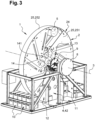
- These rotation means 5, 6 are adapted to rotate the wheel structure 2 always in the same direction of rotation (marked by an orientation arrow on the Figure 1 ).
- the rotational movement of the wheel structure 2 is transmitted to an electric generator 8 by transmission means 9.
- the electrical energy produced by the electric generator 8 is stored in electrical energy accumulation means 10 (formed here by a set of batteries) by means of a charge regulator 11, before being transformed into alternating current, via a conventional inverter-converter 12 (for example of the 230 VAC type), for any desired use.
- the support 4 of the wheel 2 is in the form of a base 41 from which two parallel vertical beams 42 extend upwards.
- the wheel structure 2 is placed between the two vertical beams 42.
- these two beams 42 carry the wheel shaft 31, by means of bearings.
- the wheel structure 2 comprises a mechanically welded chassis 21 of generally cylindrical shape, from which extends an arm 22 whose distal end 23, located at a distance from the axis 3, is equipped with the heavy mass 5.
- the arm 22 extends radially relative to the wheel shaft 31.
- the heavy mass 5 is fixedly mounted at the distal end 23 of this radial arm 22.
- the heavy mass 5 is unique here, but we can consider a plurality of masses assembled together.
- the heavy mass 5 is mounted fixed at the level of the peripheral zone 24 of the wheel structure 2.
- This heavy mass 5 is preferably made of metal (steel, lead, etc.).
- the wheel drive motor 6 and the electric generator 8 are carried by the vertical beams 42 of the wheel support 4, in the extension of the rotation shaft 31.
- the wheel drive motor 6 is mounted on one side of the wheel structure 2 and its output is engaged with the wheel shaft 31 via the transmission means 7 in the form of an electromagnetic clutch.
- This wheel drive motor 6 may consist of an electric servomotor-type geared motor coupled to a planetary reducer.
- the electric generator 8 is mounted on the other side of the wheel 2 and its axis is engaged with the wheel shaft 31 by means of the transmission means 9 in the form of a multiplier gearbox.
- the electric generator 8 may consist of an 800ATK4M1C0100 permanent magnet alternator which can produce from 0 to 22 KW depending on its speed.
- the electrical energy required for the operation of the wheel drive motor 6 comes from the electrical energy storage means 10, which receive an additional charge from an external electrical power supply, for example the mains.
- the various constituent elements of the transmission means 7 of the wheel maneuvering motorization 6 are adapted to obtain a chosen rotation speed of the wheel structure 2.
- the various constituent elements of the transmission means 9 are adapted to rotate the axis of the electric generator 8 at a chosen speed, preferably at its nominal speed (that is to say at the speed at which it delivers its maximum power).
- An electronic module (not shown) constitutes control means suitable for managing the operation of the equipment 1.
- this electronic module is configured/programmed to manage the operation of the wheel maneuvering motorization 6 so as, after initiation of the movement, to stabilize the rotation of the wheel structure 2 at a predefined value (adapted to the nominal speed sought for the electric generator 8).
- this electronic module is adapted to allow the wheel maneuver motorization 6 (and therefore the wheel structure 2) to be started and stopped depending on the charge level of the electrical energy accumulation means 10.
- the wheel maneuver motorization 6 will only be able to start from a certain charge level of the electrical energy accumulation means 10 (for example 30%); and it will also stop from reaching a certain charge level (for example 100%).
- this electronic module is adapted to stop the wheel structure 2 with the heavy mass 5 positioned in the upper part vertically of the axis 3, so as to facilitate the restarting of the wheel structure 2 due to gravity.
- the equipment 1 advantageously comprises braking/locking means 13 which here consist of a disc braking device, comprising - a jaw 131 carried by the support 4, and - a disc 132 carried by the wheel shaft 31.
- braking/locking means 13 which here consist of a disc braking device, comprising - a jaw 131 carried by the support 4, and - a disc 132 carried by the wheel shaft 31.
- the management of these locking means 13 by the electronic module is assisted by an encoder 14 actuated by the wheel shaft 31 via a transmission belt 141.
- This encoder 14 makes it possible to know precisely the position of the heavy mass 5, as well as the rotation speed of the wheel structure 2.
- the weight of the heavy mass 5 can be of the order of 600 kg, and its distance from the axis of the order of 1.50 m, which corresponds to a torque of approximately 9000 newton-meters.
- the wheel drive 6 and the electronic module control the equipment so that the heavy mass 5 falls in free fall at a speed of approximately 40 rpm. At this speed, the electric generator produces more than 5 kW and creates a resistive torque of approximately 2100 newton meters.
- the wheel structure 2 being stationary, with its heavy mass 5 positioned in the upper part vertically above the axis of rotation 3, the wheel maneuvering motor 6 can be started to rotate the wheel structure 2. The initiation of rotation is facilitated by the weight of the heavy mass 5.
- the wheel structure 2 is accelerated, then stabilized in speed so that the electric generator 8 rotates at its nominal speed and produces an electric current ensuring the charging of the electrical energy accumulation means 10.
- the single heavy mass 5 thus acts as an unbalance at the end of the arm 22, which combines the effect of inertia and that of centrifugal force.
- the electric generator 8 then rotates at its nominal speed and at its nominal torque, with low consumption of the wheel drive motor 6.
- the wheel drive motor 6 is stopped when the electrical energy storage means 10 are fully charged.
- the electrical energy storage means 10 can be used for any chosen electrical supply, for example within a home or other.
- the wheel structure 2 here comprises a mechanically welded chassis of generally cylindrical shape on which is attached a peripheral fairing 25 adapted to minimize air friction.
- the fairing 25 here consists of - two lateral flanges 251, in the general shape of discs, which extend in a vertical plane, parallel to each other, and - a peripheral cylindrical shell 252.
- the side plates 251 and the peripheral ferrule 252 can be made in one or more pieces.
- the wheel structure 2 carries the heavy mass 5 in its peripheral zone 24, that is to say at a distance from the axis 3, protected by the fairing 25.
- the heavy mass 5 is unique; it is preferably made of metal (steel, lead, etc.) and here it is in a cylindrical form interposed between the two flanges 251. This heavy mass 5 is fixed relative to the chassis of the wheel structure 2, secured to the latter by any appropriate means.
- the heavy mass 5 can take other forms and can be made up of several modules, preferably close to each other.
Landscapes
- Engineering & Computer Science (AREA)
- Chemical & Material Sciences (AREA)
- Combustion & Propulsion (AREA)
- Mechanical Engineering (AREA)
- General Engineering & Computer Science (AREA)
- Connection Of Motors, Electrical Generators, Mechanical Devices, And The Like (AREA)
Claims (10)
- Vorrichtung für ein elektrisches Netzwerk, die für eine Speicherung von Energie in Form von Gravitationspotentialenergie und die Rückgewinnung der Gravitationspotentialenergie in Form von elektrischer Energie ausgelegt ist, wobei die Vorrichtung (1)- eine Radstruktur (2) mit einer drehenden Welle (31), die eine horizontale Drehachse (3) hat,- Mittel (5, 6) zum in Drehung Versetzen der Radstruktur (2) um die horizontale Drehachse (3), wobei die Mittel (5, 6) (i) mindestens eine von der Radstruktur (2) so getragene Gewichtsmasse (5), daß deren Ungleichgewicht in Bezug auf die Drehachse (3) sichergestellt ist, und (ii) eine mit Übertragungsmitteln (7) verbundene Radbetätigungsmotorisierung (6) aufweisen,- einen elektrischen Generator (8) mit einem durch die drehende Welle (31) drehend angetriebenen Rotor für die Erzeugung elektrischer Energie aus der Drehung der Radstruktur (2) und- Mittel zum Sammeln elektrischer Energie (10) in Form von einer oder mehreren Batterien, die durch den elektrischen Generator (8) mit Elektrizität versorgt werden,aufweist,
dadurch gekennzeichnet, daß die Mittel (5, 6) zum in Drehung Versetzen der Radstruktur (2) dazu ausgelegt sind, die Radstruktur (2) immer im selben Drehsinn in Drehung zu versetzen. - Vorrichtung gemäß Anspruch 1, dadurch gekennzeichnet, daß die mindestens eine Gewichtsmasse (5) aus einer einzigen Gewichtsmasse besteht.
- Vorrichtung gemäß einem der Ansprüche 1 oder 2, dadurch gekennzeichnet, daß die mindestens eine Gewichtsmasse (5) an der Radstruktur (2) fest angebracht ist.
- Vorrichtung gemäß Anspruch 3, dadurch gekennzeichnet, daß die Radstruktur (2) eine von der horizontalen Drehachse (3) entfernt angeordnete Randzone (24) aufweist und daß die mindestens eine Gewichtsmasse (5) in Höhe der Randzone (24) fest angebracht ist.
- Vorrichtung gemäß Anspruch 4, dadurch gekennzeichnet, daß die Radstruktur (2) eine im Wesentlichen zylindrische Form hat und eine zum Reduzieren der Luftreibung ausgelegte Umfangsverkleidung (25, 251, 252) aufweist.
- Vorrichtung gemäß Anspruch 3, dadurch gekennzeichnet, daß die Radstruktur (2) einen sich in Bezug auf die drehende Welle (31) radial erstreckenden Arm (22) aufweist, an dessen distalem Ende die mindestens eine Gewichtsmasse (5) fest angebracht ist.
- Vorrichtung gemäß einem der Ansprüche 1 bis 6, dadurch gekennzeichnet, daß die Radbetätigungsmotorisierung (6) elektrisch ist und daß die Mittel zum Sammeln elektrischer Energie (10) dazu ausgelegt sind, mindestens teilweise als Stromversorgungsmittel für die Radbetätigungsmotorisierung (6) zu dienen.
- Vorrichtung gemäß Anspruch 7, dadurch gekennzeichnet, daß sie Steuerungsmittel aufweist, die für das in Bewegung Setzen und Anhalten der Radbetätigungsmotorisierung (6) in Abhängigkeit vom Ladezustand der Mittel zum Sammeln elektrischer Energie (10) ausgelegt sind.
- Vorrichtung gemäß einem der Ansprüche 1 bis 8, dadurch gekennzeichnet, daß sie Steuerungsmittel für die Radbetätigungsmotorisierung (6) aufweist, die dazu ausgelegt sind, die Radstruktur (2) anzuhalten, indem die mindestens eine Gewichtsmasse (5) im oberen Teil der Radstruktur (2) senkrecht oder im Wesentlichen senkrecht über der Drehachse (3) der Radstruktur (2) positioniert wird, um deren gravitationsbedingtes in Drehung Versetzen zu erleichtern.
- Verfahren zur drehenden Betätigung einer Vorrichtung gemäß einem der Ansprüche 1 bis 9, dadurch gekennzeichnet, daß es darin besteht,- die Radstruktur (2) anzuhalten, indem die mindestens eine Gewichtsmasse (5) im oberen Teil der Radstruktur (2) senkrecht oder im Wesentlichen senkrecht über der Drehachse (3) der Radstruktur (2) positioniert wird, um deren gravitationsbedingtes in Drehung Versetzen zu erleichtern, und- die Radbetätigungsmotorisierung (6) in Gang zu setzen, um die Radstruktur (2) drehend anzutreiben.
Applications Claiming Priority (2)
| Application Number | Priority Date | Filing Date | Title |
|---|---|---|---|
| FR2006618A FR3111956B1 (fr) | 2020-06-24 | 2020-06-24 | Equipement pour réseau électrique, adapté au stockage d’énergie sous forme d’énergie potentielle de pesanteur |
| PCT/EP2021/067215 WO2021260045A1 (fr) | 2020-06-24 | 2021-06-23 | Equipement pour reseau electrique, adapte au stockage d'energie sous forme d'energie potentielle de pesanteur |
Publications (3)
| Publication Number | Publication Date |
|---|---|
| EP4172499A1 EP4172499A1 (de) | 2023-05-03 |
| EP4172499B1 true EP4172499B1 (de) | 2025-04-02 |
| EP4172499C0 EP4172499C0 (de) | 2025-04-02 |
Family
ID=72560825
Family Applications (1)
| Application Number | Title | Priority Date | Filing Date |
|---|---|---|---|
| EP21735681.5A Active EP4172499B1 (de) | 2020-06-24 | 2021-06-23 | Vorrichtung für elektrische netzwerke, wobei die vorrichtung zur speicherung von energie in form von gravitationspotentialenergie geeignet ist |
Country Status (3)
| Country | Link |
|---|---|
| EP (1) | EP4172499B1 (de) |
| FR (1) | FR3111956B1 (de) |
| WO (1) | WO2021260045A1 (de) |
Families Citing this family (3)
| Publication number | Priority date | Publication date | Assignee | Title |
|---|---|---|---|---|
| FR3140654A1 (fr) * | 2022-10-06 | 2024-04-12 | Roméo GEROLAMI | Ensemble de motorisation à effet gravitationnel |
| US12025107B1 (en) * | 2023-10-28 | 2024-07-02 | Syed SHAH | Power generation system and method |
| WO2024246733A1 (en) * | 2023-06-01 | 2024-12-05 | Syed Shah | Power generation system and method |
Family Cites Families (2)
| Publication number | Priority date | Publication date | Assignee | Title |
|---|---|---|---|---|
| CN105275755A (zh) * | 2014-07-10 | 2016-01-27 | 俞伽达企业股份有限公司 | 钟摆式节能发电装置 |
| FR3079885B1 (fr) * | 2018-04-10 | 2022-07-01 | Jacques Pitoux | Equipement pour les reseaux electriques, adaptes au stockage et a la restitution d'energie potentielle de pesanteur |
-
2020
- 2020-06-24 FR FR2006618A patent/FR3111956B1/fr active Active
-
2021
- 2021-06-23 WO PCT/EP2021/067215 patent/WO2021260045A1/fr not_active Ceased
- 2021-06-23 EP EP21735681.5A patent/EP4172499B1/de active Active
Also Published As
| Publication number | Publication date |
|---|---|
| FR3111956A1 (fr) | 2021-12-31 |
| EP4172499A1 (de) | 2023-05-03 |
| WO2021260045A1 (fr) | 2021-12-30 |
| FR3111956B1 (fr) | 2022-12-16 |
| EP4172499C0 (de) | 2025-04-02 |
Similar Documents
| Publication | Publication Date | Title |
|---|---|---|
| EP4172499B1 (de) | Vorrichtung für elektrische netzwerke, wobei die vorrichtung zur speicherung von energie in form von gravitationspotentialenergie geeignet ist | |
| EP1115977B1 (de) | Windturbine mit gegenläufigen rotoren | |
| EP0864748B1 (de) | Langsamlaufende getriebelose Windturbine | |
| WO2001098655A1 (fr) | Dispositif de production de courant electrique a partir d'energie eolienne | |
| EP1540177A2 (de) | Mit zwei gegenläufigen spindeln versehene antriebsvorrichtung für eine windmühle | |
| FR2927312A1 (fr) | Dispositif d'actionneur pour varier l'attitude d'un engin spatial | |
| EP3331654B1 (de) | Oszillierender mechanismus mit gleichzeitigen querzentrifugalkräften, maschine und verfahren zur verwendung davon | |
| WO2011051598A2 (fr) | Demarreur-generateur de turbomachine et procede pour sa commande. | |
| EP0152339B1 (de) | Elektrische Antriebseinrichtung bei niedriger Spannung einer drehenden Masse grosser Trägheit und Motor als Teil einer solchen Einrichtung | |
| FR2982441A1 (fr) | Machine synchrone hybride. | |
| FR2871961A1 (fr) | Appareil de generation d'energie d'alimentation pour generateur d'electricite | |
| WO2019197762A1 (fr) | Equipement pour les réseaux électriques, adaptés au stockage et à la restitution d'énergie potentielle de pesanteur | |
| EP3706934B1 (de) | Vorrichtung und verfahren zur herstellung eines metalllegierungsrohlings durch schleudergiessen | |
| FR2975842A1 (fr) | Dispositif d'alimentation electrique d'au moins un equipement d'un rotor tournant d'un aeronef, et aeronef | |
| FR2962180A1 (fr) | Dispositifs de transmission, groupe moto propulseur, accumulateur d'energie, et vehicule ainsi equipe | |
| CA2891607A1 (fr) | Systeme d'alimentation electrique sans coupure | |
| EP3632731A1 (de) | Zugvorrichtung für fahrzeug | |
| EP0835806A1 (de) | Antriebsvorrichtung für die Drehbewegung des Armes einer Zentrifuge grosser Abmessungen | |
| EP0343313A1 (de) | Elektrischer Motor hoher Leistung und hoher Umdrehungsgeschwindigkeit | |
| EP0337863A1 (de) | Rotationsantriebsvorrichtung für einen Zentrifugenarm und Energieversorgungsmethode für eine solche Vorrichtung | |
| WO2022229185A1 (fr) | Moteur à création de moment cinétique | |
| EP2388491B1 (de) | Hysteresisvorrichtung um eine Welle und eine Rolle zu koppeln und Motorblock mit einer solchen Vorrichtung | |
| EP0024977B1 (de) | Verfahren und Vorrichtung zur Arretierung eines Vertikalkreisels | |
| FR2484026A2 (fr) | Station de captation de l'energie eolienne | |
| EP4296505A1 (de) | Windturbine mit vertikaler achse und kraftwerk |
Legal Events
| Date | Code | Title | Description |
|---|---|---|---|
| STAA | Information on the status of an ep patent application or granted ep patent |
Free format text: STATUS: UNKNOWN |
|
| STAA | Information on the status of an ep patent application or granted ep patent |
Free format text: STATUS: THE INTERNATIONAL PUBLICATION HAS BEEN MADE |
|
| PUAI | Public reference made under article 153(3) epc to a published international application that has entered the european phase |
Free format text: ORIGINAL CODE: 0009012 |
|
| STAA | Information on the status of an ep patent application or granted ep patent |
Free format text: STATUS: REQUEST FOR EXAMINATION WAS MADE |
|
| 17P | Request for examination filed |
Effective date: 20221220 |
|
| AK | Designated contracting states |
Kind code of ref document: A1 Designated state(s): AL AT BE BG CH CY CZ DE DK EE ES FI FR GB GR HR HU IE IS IT LI LT LU LV MC MK MT NL NO PL PT RO RS SE SI SK SM TR |
|
| DAV | Request for validation of the european patent (deleted) | ||
| DAX | Request for extension of the european patent (deleted) | ||
| REG | Reference to a national code |
Ref country code: DE Ref legal event code: R079 Free format text: PREVIOUS MAIN CLASS: F03G0003080000 Ipc: F03G0003000000 Ref document number: 602021028530 Country of ref document: DE |
|
| GRAP | Despatch of communication of intention to grant a patent |
Free format text: ORIGINAL CODE: EPIDOSNIGR1 |
|
| STAA | Information on the status of an ep patent application or granted ep patent |
Free format text: STATUS: GRANT OF PATENT IS INTENDED |
|
| RIC1 | Information provided on ipc code assigned before grant |
Ipc: F03G 3/00 20060101AFI20241001BHEP |
|
| INTG | Intention to grant announced |
Effective date: 20241024 |
|
| GRAS | Grant fee paid |
Free format text: ORIGINAL CODE: EPIDOSNIGR3 |
|
| GRAA | (expected) grant |
Free format text: ORIGINAL CODE: 0009210 |
|
| STAA | Information on the status of an ep patent application or granted ep patent |
Free format text: STATUS: THE PATENT HAS BEEN GRANTED |
|
| AK | Designated contracting states |
Kind code of ref document: B1 Designated state(s): AL AT BE BG CH CY CZ DE DK EE ES FI FR GB GR HR HU IE IS IT LI LT LU LV MC MK MT NL NO PL PT RO RS SE SI SK SM TR |
|
| REG | Reference to a national code |
Ref country code: GB Ref legal event code: FG4D Free format text: NOT ENGLISH |
|
| REG | Reference to a national code |
Ref country code: CH Ref legal event code: EP |
|
| REG | Reference to a national code |
Ref country code: IE Ref legal event code: FG4D Free format text: LANGUAGE OF EP DOCUMENT: FRENCH |
|
| REG | Reference to a national code |
Ref country code: DE Ref legal event code: R096 Ref document number: 602021028530 Country of ref document: DE |
|
| U01 | Request for unitary effect filed |
Effective date: 20250424 |
|
| U07 | Unitary effect registered |
Designated state(s): AT BE BG DE DK EE FI FR IT LT LU LV MT NL PT RO SE SI Effective date: 20250502 |
|
| U20 | Renewal fee for the european patent with unitary effect paid |
Year of fee payment: 5 Effective date: 20250612 |
|
| PG25 | Lapsed in a contracting state [announced via postgrant information from national office to epo] |
Ref country code: ES Free format text: LAPSE BECAUSE OF FAILURE TO SUBMIT A TRANSLATION OF THE DESCRIPTION OR TO PAY THE FEE WITHIN THE PRESCRIBED TIME-LIMIT Effective date: 20250402 |
|
| PG25 | Lapsed in a contracting state [announced via postgrant information from national office to epo] |
Ref country code: NO Free format text: LAPSE BECAUSE OF FAILURE TO SUBMIT A TRANSLATION OF THE DESCRIPTION OR TO PAY THE FEE WITHIN THE PRESCRIBED TIME-LIMIT Effective date: 20250702 Ref country code: GR Free format text: LAPSE BECAUSE OF FAILURE TO SUBMIT A TRANSLATION OF THE DESCRIPTION OR TO PAY THE FEE WITHIN THE PRESCRIBED TIME-LIMIT Effective date: 20250703 |
|
| PG25 | Lapsed in a contracting state [announced via postgrant information from national office to epo] |
Ref country code: PL Free format text: LAPSE BECAUSE OF FAILURE TO SUBMIT A TRANSLATION OF THE DESCRIPTION OR TO PAY THE FEE WITHIN THE PRESCRIBED TIME-LIMIT Effective date: 20250402 |
|
| PG25 | Lapsed in a contracting state [announced via postgrant information from national office to epo] |
Ref country code: HR Free format text: LAPSE BECAUSE OF FAILURE TO SUBMIT A TRANSLATION OF THE DESCRIPTION OR TO PAY THE FEE WITHIN THE PRESCRIBED TIME-LIMIT Effective date: 20250402 |
|
| PG25 | Lapsed in a contracting state [announced via postgrant information from national office to epo] |
Ref country code: RS Free format text: LAPSE BECAUSE OF FAILURE TO SUBMIT A TRANSLATION OF THE DESCRIPTION OR TO PAY THE FEE WITHIN THE PRESCRIBED TIME-LIMIT Effective date: 20250702 |
|
| PG25 | Lapsed in a contracting state [announced via postgrant information from national office to epo] |
Ref country code: IS Free format text: LAPSE BECAUSE OF FAILURE TO SUBMIT A TRANSLATION OF THE DESCRIPTION OR TO PAY THE FEE WITHIN THE PRESCRIBED TIME-LIMIT Effective date: 20250802 |
|
| PG25 | Lapsed in a contracting state [announced via postgrant information from national office to epo] |
Ref country code: SM Free format text: LAPSE BECAUSE OF FAILURE TO SUBMIT A TRANSLATION OF THE DESCRIPTION OR TO PAY THE FEE WITHIN THE PRESCRIBED TIME-LIMIT Effective date: 20250402 |
|
| PG25 | Lapsed in a contracting state [announced via postgrant information from national office to epo] |
Ref country code: CZ Free format text: LAPSE BECAUSE OF FAILURE TO SUBMIT A TRANSLATION OF THE DESCRIPTION OR TO PAY THE FEE WITHIN THE PRESCRIBED TIME-LIMIT Effective date: 20250402 |
|
| PG25 | Lapsed in a contracting state [announced via postgrant information from national office to epo] |
Ref country code: SK Free format text: LAPSE BECAUSE OF FAILURE TO SUBMIT A TRANSLATION OF THE DESCRIPTION OR TO PAY THE FEE WITHIN THE PRESCRIBED TIME-LIMIT Effective date: 20250402 |
|
| REG | Reference to a national code |
Ref country code: CH Ref legal event code: H13 Free format text: ST27 STATUS EVENT CODE: U-0-0-H10-H13 (AS PROVIDED BY THE NATIONAL OFFICE) Effective date: 20260127 |
|
| PG25 | Lapsed in a contracting state [announced via postgrant information from national office to epo] |
Ref country code: MC Free format text: LAPSE BECAUSE OF FAILURE TO SUBMIT A TRANSLATION OF THE DESCRIPTION OR TO PAY THE FEE WITHIN THE PRESCRIBED TIME-LIMIT Effective date: 20250402 |
|
| PLBE | No opposition filed within time limit |
Free format text: ORIGINAL CODE: 0009261 |
|
| STAA | Information on the status of an ep patent application or granted ep patent |
Free format text: STATUS: NO OPPOSITION FILED WITHIN TIME LIMIT |
|
| REG | Reference to a national code |
Ref country code: CH Ref legal event code: L10 Free format text: ST27 STATUS EVENT CODE: U-0-0-L10-L00 (AS PROVIDED BY THE NATIONAL OFFICE) Effective date: 20260211 |
|
| 26N | No opposition filed |
Effective date: 20260105 |
|
| GBPC | Gb: european patent ceased through non-payment of renewal fee |
Effective date: 20250702 |
|
| PG25 | Lapsed in a contracting state [announced via postgrant information from national office to epo] |
Ref country code: GB Free format text: LAPSE BECAUSE OF NON-PAYMENT OF DUE FEES Effective date: 20250702 |
|
| PG25 | Lapsed in a contracting state [announced via postgrant information from national office to epo] |
Ref country code: IE Free format text: LAPSE BECAUSE OF NON-PAYMENT OF DUE FEES Effective date: 20250623 |