EP4172437B1 - Verriegelungsvorrichtung für türen oder fenster - Google Patents
Verriegelungsvorrichtung für türen oder fenster Download PDFInfo
- Publication number
- EP4172437B1 EP4172437B1 EP21743576.7A EP21743576A EP4172437B1 EP 4172437 B1 EP4172437 B1 EP 4172437B1 EP 21743576 A EP21743576 A EP 21743576A EP 4172437 B1 EP4172437 B1 EP 4172437B1
- Authority
- EP
- European Patent Office
- Prior art keywords
- door
- window
- break
- movement
- locking pin
- Prior art date
- Legal status (The legal status is an assumption and is not a legal conclusion. Google has not performed a legal analysis and makes no representation as to the accuracy of the status listed.)
- Active
Links
Images

Classifications
-
- E—FIXED CONSTRUCTIONS
- E05—LOCKS; KEYS; WINDOW OR DOOR FITTINGS; SAFES
- E05B—LOCKS; ACCESSORIES THEREFOR; HANDCUFFS
- E05B17/00—Accessories in connection with locks
- E05B17/20—Means independent of the locking mechanism for preventing unauthorised opening, e.g. for securing the bolt in the fastening position
- E05B17/2003—Preventing opening by insertion of a tool, e.g. flexible, between door and jamb to withdraw the bolt
-
- E—FIXED CONSTRUCTIONS
- E05—LOCKS; KEYS; WINDOW OR DOOR FITTINGS; SAFES
- E05B—LOCKS; ACCESSORIES THEREFOR; HANDCUFFS
- E05B15/00—Other details of locks; Parts for engagement by bolts of fastening devices
- E05B15/10—Bolts of locks or night latches
-
- E—FIXED CONSTRUCTIONS
- E05—LOCKS; KEYS; WINDOW OR DOOR FITTINGS; SAFES
- E05C—BOLTS OR FASTENING DEVICES FOR WINGS, SPECIALLY FOR DOORS OR WINDOWS
- E05C1/00—Fastening devices with bolts moving rectilinearly
- E05C1/08—Fastening devices with bolts moving rectilinearly with latching action
- E05C1/12—Fastening devices with bolts moving rectilinearly with latching action with operating handle or equivalent member moving otherwise than rigidly with the latch
- E05C1/16—Fastening devices with bolts moving rectilinearly with latching action with operating handle or equivalent member moving otherwise than rigidly with the latch the handle or member moving essentially in a plane substantially parallel to the wing or frame
Definitions
- the present invention relates to an anti break-in door/window comprising a locking device for fixtures, such as doors, main doors, windows, leaves and the like.
- Various locking devices particularly of the type of locks and the like, are known which are generally provided with a latch mechanism mounted between the door and the frame of a corresponding fixture.
- such a latch mechanism is commonly provided with a locking pin mounted in a retractable manner on the door from which it protrudes overhanging under the effect of a spring, and at least one housing seat of such a pin obtained on the frame.
- this type of locking device uses a locking pin provided with a head portion which is cut so as to create an inclined portion that defines a chamfer on which the frame slides in abutment to allow the locking pin to return inside the door and then close the fixture.
- This solution allows the user to close the fixture quickly and easily by simply pushing the door up against the corresponding frame.
- the locking devices of known type generally comprise opening means for opening the fixture of the manual type, e.g., of the type of a handle, a knob or the like, used by the user of the fixture to extract the locking pin from the respective housing seat and permit opening of the fixture.
- this type of device comprises locking means for locking the doors/windows, such as e.g., a cylinder operated by a corresponding key, adapted to lock the opening means and the locking pin, thus preventing the latter from retracting.
- locking means for locking the doors/windows such as e.g., a cylinder operated by a corresponding key, adapted to lock the opening means and the locking pin, thus preventing the latter from retracting.
- This operation allows the door/window to close, but is not enough to ensure the security of the closure.
- the locking pin in fact, may be easily retracted by inserting a flexible sheet into the slot of the fixture, e.g., a piece of sheet or a credit card, adapted to operate on the head portion of the pin.
- the key To ensure the security of the closure, the key must be turned so that one or more bolts slide into the appropriate closure seats.
- This operation is usually carried out at night, from the inside, to ensure greater peace of mind for those who are preparing to go to bed.
- the main aim of the present invention is to devise an anti break-in door/ window comprising a locking device which enables an automatic closure of the door/window in an effective, quick, safe and practical manner.
- a further object of the present invention is to devise a locking device which can also be installed and used on existing fixtures.
- Another object of the present invention is to devise a locking device which is compatible with existing locks.
- Another object of the present invention is to devise a locking device which allows overcoming the aforementioned drawbacks of the prior art within a simple, rational, easy and effective to use as well as affordable solution.
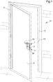
- reference numeral 1 globally indicates a locking device.
- the locking device 1 for doors/windows comprises:
- the device 1 comprises anti break-in means 12, 13 adapted, in the closure configuration, to prevent the locking pin 4 from moving from the forward position to the backward position by means of the break-in means 17 adapted to forcibly move the locking pin 4 from the forward position to the backward position.
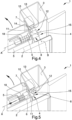
- the locking pin 4 extends longitudinally along the direction of movement A and comprises at least one protruding portion 8 extending overhanging from the supporting frame 5 and which has at least one extreme wall 11 inclined with respect to the direction of movement A.
- the extreme wall 11 lies on an inclined plane D.
- the inclined plane D is arranged inclined with respect to a plane orthogonal to the direction of movement A.
- the second portion 3 comprises at least one abutment body 10 adapted to abut against the extreme wall 11 during the movement between the opening configuration and the closure configuration to move the locking pin 4 from the forward position to the backward position.
- the abutment body 10 extends along a direction of extension orthogonal to the direction of movement A.
- the supporting frame 5 defines at least one transit hole 6 of the locking pin 4.
- the locking pin 4 is arranged overhanging the supporting frame 5 through the transit hole 6.
- the first and second portions 2, 3 are abutting each other, and in the opening configuration the first and second portions 2, 3 are far away from each other, as is generally the case with reference to the doors/windows 2, 3 of known type.
- the locking pin 4 is insertable in a removable manner inside a corresponding housing seat 7.
- the housing seat 7 is made on a template associated with the second portion 3 of the doors/windows 2, 3 or made directly on the same second portion.
- the housing seat 7 faces the locking pin 4.
- the elastic return means 18 are of the type of an elastically deformable body, e.g., of the type of a spring, coupled to the locking pin 4.
- the operating means 19 are adapted to move the locking pin 4 from the forward position to the backward position by means of the locking pin 4 itself.
- the return means 18 tend to return the locking pin 4 to the forward position.
- the operating means 19 are of the type of a gripping element, e.g., of the type of a handle, a knob or the like, which can be manually operated by a user of the device 1.
- the return means 18 are adapted to automatically move the locking pin 4 from the backward position to the forward position.
- the inclined wall 11 abuts against the abutment body 10, which slides in contact with the inclined wall 11.
- the abutment body 10 pushes the locking pin 4 to the backward position and causes at least the partial loading of the return means 18.
- the inclined wall 11 is moved away from the abutment body 10 and the return means 18 are unloaded, pushing the locking pin 4 to the forward position.
- control means 19, 20 comprise turning means 20 adapted to move the locking pin 4 between the forward position and at least one of:
- the turning means 20 are adapted to move the locking pin 4 between the forward position and the backward position and between the forward position and at least one further forward position.
- the turning means 20 are adapted to insert the locking pin 4 more deeply into the housing seat 7.
- the turning means 20 are adapted to bring the locking pin 4 to the backward position, so as to allow the movement of the door/window 2, 3 from the closure configuration to the opening configuration.
- the turning means 20 comprise at least one drum and at least one key insertable in a removable manner inside the drum and rotatable inside it to move the locking pin 4.
- the first portion 2 is of the type of a flat-shaped hinged body, e.g., such as e.g. the main door of a security door or the like.
- the first portion 2 lies on a lying plane C.
- the second portion 3 is of the type of a stop body, e.g., such as a doorjamb or the like, adapted to operate in conjunction with the hinged body to close/open the door/window 2, 3.
- the first portion 2 and the second portion 3 lie on the same lying plane C, so as to close the door/window 2, 3.
- the first portion 2 and the second portion 3 lie on two different planes, so as to open the door/window 2, 3.
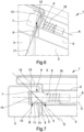
- the first and second portions 2, 3 define an interstice 9 crossed by the locking pin 4 in the forward position, as shown in Figures 6 and 7 .
- break-in means 17 reach the locking pin 4 and operate thereon to force it backwards from the forward position to the backward position.
- break-in means 17 means a flexible foil-shaped body adapted to be inserted inside the interstice 9 to easily reach the locking pin 4.
- Break-in means with different conformations cannot however be ruled out.
- the anti break-in means 12, 13 comprise:
- the blockage body 12 hinders the passage of the break-in means 17 along the interstice 9, thus preventing the extreme wall 11 from being reached.
- the blockage body 12 is provided with at least one blockage profile 14 extending longitudinally along the direction of movement A by a predefined length and adapted to abut against the break-in means 17, thus preventing the extreme wall 11 from being reached.
- the predefined length is less than or equal to the extension of the extreme wall 11 along the direction of movement A.
- the blockage profile 14 extends along the direction of movement A by a length equal to the extension of the extreme wall 11 along the same direction.
- the length of the projection of the blockage profile 14 along the direction of movement A coincides with the length of the projection of the blockage body 12 along the same direction.
- the predefined length is greater than or equal to the extension of the extreme wall 11 along the direction of movement A.
- the blockage body 12 comprises a supporting profile 15 interposed between the blockage profile 14 and the extreme wall 11 along a direction of extension B transverse with respect to the direction of movement A.
- the direction of extension B is arranged orthogonal to the direction of movement A.
- the supporting profile 15 imparts greater rigidity to the blockage profile 14.
- the extension of the blockage body 12 is delimited by the blockage profile 14, by the supporting profile 15 and by the extreme wall 11.
- the blockage profile 14, the supporting profile 15 and the extreme wall 11 define a blockage body 12 of substantially triangular conformation.
- the protruding portion 8 in cross-section has a rectangular or square profile as shown in Figure 6 .
- the cross-section of the protruding portion 8 shown in Figure 6 is obtained along a plane orthogonal to the lying plane C.
- the blockage body 12 extends along the inclined wall 11 dividing it into two inclined portions 11a, 11b.
- the blockage body 12 longitudinally divides the inclined wall 11 in half, as shown in Figures 2 and 3 .
- the anti break-in means 12, 13 comprise a plurality of blockage bodies 12 associated with the inclined wall 11 substantially spaced apart and parallel to each other. Furthermore, in this embodiment, the anti break-in means 12, 13 comprise a plurality of grooves 13 made on the abutment body 10 spaced apart and parallel to each other.
- the blockage body 12 comprises a front face 16 defining the blockage profile 14.
- the front face 16 lies on the lying plane C.
- the front face 16 is substantially flat.
- the inclined wall 11 lies on the inclined plane D, which is arranged crossways to the lying plane C.
- the lying plane C and the inclined plane D contain an axis of reference E arranged orthogonal to the direction of movement A, as shown in Figure 7 .
- the axis of reference E lies on the lying plane C and on the inclined plane D.
- the blockage body 12 lies on a plane orthogonal to the lying plane C.
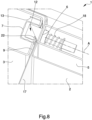
- FIG. 8 A further embodiment of the device 1 is shown in Figure 8 , wherein the blockage body 12 comprises at least one recess 22 adapted to receive the break-in means 17.
- the recess 22 extends along a direction of extension parallel to the inclined plane D.
- the recess 22 is arranged at the interstice 9.
- the recess 22 faces the interstice 9, so as to intercept the break-in means 17, preventing the locking pin 4 from being forcibly retracted, as shown in Figure 8 .
- the device 1 is a lock.
- the locking pin 4, the control means 19, 20, the return means 18 and the anti break-in means 12, 13 are inserted in the supporting frame 5 to define the lock.
- Further embodiments of the device 1 cannot however be ruled out wherein the same is a diverter.
- the control means 19, 20 of the diverter are kinematically connectable to an actuating rod insertable in the supporting frame 5 and adapted to control the same control means 19, 20.
- the actuating rod may be positioned between the diverter and a lock through which the control means 19, 20 of the diverter are operable.
- the present invention relates to an anti break-in door/window 21, comprising:
- the anti break-in means allow the automatic closure of the door/window in an effective, quick, safe and practical way.
- the extreme wall allows moving the door/window from the opening configuration to the closure configuration in an automatic, practical and quick manner.
- the blockage body and the groove allow closing the door/window without interfering with its automatic closure and preventing it from being forced open by break-in means.
- break-in means can also be installed and used on existing doors/windows.
Landscapes
- Engineering & Computer Science (AREA)
- Mechanical Engineering (AREA)
- Wing Frames And Configurations (AREA)
- Bidet-Like Cleaning Device And Other Flush Toilet Accessories (AREA)
- Gripping Jigs, Holding Jigs, And Positioning Jigs (AREA)
- Body Structure For Vehicles (AREA)
Claims (10)
- Einbruchhemmende Tür/ einbruchhemmendes Fenster (21), umfassend:- mindestens eine Verriegelungsvorrichtung (1) für Türen/Fenster, umfassend:- mindestens einen Stützrahmen (5), der an einem ersten Abschnitt (2) einer Tür/eines Fensters (2, 3) angebracht ist, der zwischen mindestens einer Schließkonfiguration und mindestens einer Öffnungskonfiguration zu einem zweiten Abschnitt (3) der Tür/des Fensters (2, 3) hin und von diesem weg bewegt werden kann;- mindestens einen Verriegelungsstift (4), der entlang einer Bewegungsrichtung (A) zwischen mindestens einer vorderen Position und mindestens einer hinteren Position verschiebbar ist und an dem Tragrahmen (5) angebracht ist;- Steuermittel (19, 20), die mit Betätigungsmitteln (19) versehen sind, die ausgebildet sind, um den Verriegelungsstift (4) von der vorderen Position in die hintere Position zu bewegen;- Rückstellmittel (18), die mit dem Verriegelungsstift (4) gekoppelt und ausgebildet sind, um diesen von der rückwärtigen Position in die vordere Position zu bewegen;- Einbruchschutzmittel (12, 13), die in der Verschlusskonfiguration ausgebildet sind, um zu verhindern, dass sich der Verriegelungsstift (4) von der vorderen Position in die hintere Position bewegt, und zwar mittels Einbruchmitteln (17), die ausgebildet sind, um den Verriegelungsstift (4) zwangsweise von der vorderen Position in die hintere Position zu bewegen;- den ersten und zweiten Abschnitt (2, 3) der Tür/des Fensters;- wobei der Verriegelungsstift (4) sich in Längsrichtung entlang der Bewegungsrichtung (A) erstreckt und mindestens einen vorstehenden Abschnitt (8) umfasst, der sich überhängend von dem Tragrahmen (5) erstreckt und mindestens eine äußerste Wand (11) aufweist, die in Bezug auf die Bewegungsrichtung (A) geneigt ist;- wobei der zweite Abschnitt (3) mindestens einen Anschlagkörper (10) umfasst, der ausgebildet ist, um während der Bewegung zwischen der Öffnungskonfiguration und der Schließkonfiguration gegen die äußerste Wand (11) zu stoßen, um den Verriegelungsstift (4) von der vorderen Position in die hintere Position zu bewegen; dadurch gekennzeichnet, dass- die Einbruchschutzmittel (12, 13) umfassen:- mindestens einen Sperrkörper (12), der mit der Außenwand (11) verbunden ist, so angeordnet ist, dass er entlang der Bewegungsrichtung (A) überhängend von dieser vorsteht, und ausgebildet ist, zu verhindern, dass die Einbruchmittel (17) die äußerste Wand (11) erreichen;- mindestens eine Nut (13), die in dem Anschlagkörper (10) ausgebildet ist, wobei der Sperrkörper (12) während der Bewegung zwischen der Öffnungskonfiguration und der Schließkonfiguration durch die Nut (13) hindurchgeht, um es dem Anschlagkörper (10) zu ermöglichen, an der äußersten Wand (11) anzuliegen.
- Einbruchhemmende Tür/ einbruchhemmendes Fenster (21) gemäß Anspruch 1, dadurch gekennzeichnet, dass der Sperrkörper (12) mit mindestens einem Blockierprofil (14) versehen ist, das sich in Längsrichtung entlang der Bewegungsrichtung (A) über eine vorgegebene Länge erstreckt und ausgebildet ist, um gegen die Einbruchmittel (17) zu stoßen, und dadurch zu verhindern, dass die äußerste Wand (11) erreicht wird.
- Einbruchhemmende Tür/ einbruchhemmendes Fenster (21) gemäß einem oder mehreren der vorhergehenden Ansprüche, dadurch gekennzeichnet, dass der Sperrkörper (12) mindestens eine Aussparung (22) umfasst, die ausgebildet ist, das Einbruchmittel (17) aufzunehmen.
- Einbruchhemmende Tür/ einbruchhemmendes Fenster (21) gemäß Anspruch 2, dadurch gekennzeichnet, dass die vorgegebene Länge kleiner oder gleich der Ausdehnung der äußersten Wand (11) entlang der Bewegungsrichtung (A) ist.
- Einbruchhemmende Tür/ einbruchhemmendes Fenster (21) gemäß Anspruch 2, dadurch gekennzeichnet, dass die vorgegebene Länge größer oder gleich der Ausdehnung der äußersten Wand (11) entlang der Bewegungsrichtung (A) ist.
- Einbruchhemmende Tür/ einbruchhemmendes Fenster (21) gemäß einem oder mehreren der vorhergehenden Ansprüche, dadurch gekennzeichnet, dass der Sperrkörper (12) ein Stützprofil (15) umfasst, das zwischen dem Blockierprofil (14) und der äußersten Wand (11) entlang einer Ausdehnungsrichtung (B) quer zu der Bewegungsrichtung (A) angeordnet ist.
- Einbruchhemmende Tür/ einbruchhemmendes Fenster (21) gemäß Anspruch 6, dadurch gekennzeichnet, dass die Ausdehnung des Sperrkörper (12) durch das Blockierprofil (14), das Stützprofil (15) und die äußerste Wand (11) begrenzt ist.
- Einbruchhemmende Tür/ einbruchhemmendes Fenster (21) gemäß Anspruch 6, dadurch gekennzeichnet, dass das Blockierprofil (14), das Stützprofil (15) und die äußerste Wand (11) einen Sperrkörper (12) mit im Wesentlichen dreieckiger Form definieren.
- Einbruchhemmende Tür/ einbruchhemmendes Fenster (21) gemäß einem oder mehreren der vorhergehenden Ansprüche, dadurch gekennzeichnet, dass die Vorrichtung (1) ein Schloss ist.
- Einbruchhemmende Tür/ einbruchhemmendes Fenster (21) gemäß einem oder mehreren der vorhergehenden Ansprüche, dadurch gekennzeichnet, dass die Vorrichtung (1) ein Um-/ Ablenker ist.
Applications Claiming Priority (2)
| Application Number | Priority Date | Filing Date | Title |
|---|---|---|---|
| IT102020000015223A IT202000015223A1 (it) | 2020-06-24 | 2020-06-24 | Dispositivo di serraggio per serramenti |
| PCT/IB2021/055625 WO2021260625A1 (en) | 2020-06-24 | 2021-06-24 | Locking device for doors/windows |
Publications (3)
| Publication Number | Publication Date |
|---|---|
| EP4172437A1 EP4172437A1 (de) | 2023-05-03 |
| EP4172437C0 EP4172437C0 (de) | 2024-11-27 |
| EP4172437B1 true EP4172437B1 (de) | 2024-11-27 |
Family
ID=72644588
Family Applications (1)
| Application Number | Title | Priority Date | Filing Date |
|---|---|---|---|
| EP21743576.7A Active EP4172437B1 (de) | 2020-06-24 | 2021-06-24 | Verriegelungsvorrichtung für türen oder fenster |
Country Status (3)
| Country | Link |
|---|---|
| EP (1) | EP4172437B1 (de) |
| IT (1) | IT202000015223A1 (de) |
| WO (1) | WO2021260625A1 (de) |
Families Citing this family (1)
| Publication number | Priority date | Publication date | Assignee | Title |
|---|---|---|---|---|
| IT202000020461A1 (it) * | 2020-08-26 | 2022-02-26 | Antonio Diez | Serratura a scrocco |
Citations (1)
| Publication number | Priority date | Publication date | Assignee | Title |
|---|---|---|---|---|
| GB1140725A (en) * | 1965-06-18 | 1969-01-22 | Josiah Parkes And Sons Ltd | Improvements in or relating to latch sets and lock sets |
Family Cites Families (5)
| Publication number | Priority date | Publication date | Assignee | Title |
|---|---|---|---|---|
| DE9411156U1 (de) * | 1994-07-09 | 1994-09-22 | Barczikowski, Anton, 61231 Bad Nauheim | Fallschloß |
| NL1036560C2 (nl) * | 2009-02-11 | 2010-08-12 | Benno Maathuis | Slot en modificatiepakket voor een slot. |
| US20110252842A1 (en) * | 2009-09-11 | 2011-10-20 | Nicholas Oral Morn | Secure slot lock-secure slots door locks |
| US8857864B2 (en) * | 2011-07-18 | 2014-10-14 | Ronald T. Snyder, JR. | Tamper proof lock and method |
| NL1039151C2 (nl) * | 2011-11-02 | 2013-05-07 | Benno Maathuis | Slot, modificatiepakket en schoot voor een slot. |
-
2020
- 2020-06-24 IT IT102020000015223A patent/IT202000015223A1/it unknown
-
2021
- 2021-06-24 WO PCT/IB2021/055625 patent/WO2021260625A1/en not_active Ceased
- 2021-06-24 EP EP21743576.7A patent/EP4172437B1/de active Active
Patent Citations (1)
| Publication number | Priority date | Publication date | Assignee | Title |
|---|---|---|---|---|
| GB1140725A (en) * | 1965-06-18 | 1969-01-22 | Josiah Parkes And Sons Ltd | Improvements in or relating to latch sets and lock sets |
Also Published As
| Publication number | Publication date |
|---|---|
| WO2021260625A1 (en) | 2021-12-30 |
| EP4172437C0 (de) | 2024-11-27 |
| IT202000015223A1 (it) | 2021-12-24 |
| EP4172437A1 (de) | 2023-05-03 |
Similar Documents
| Publication | Publication Date | Title |
|---|---|---|
| US5090754A (en) | Restrictor device with a releasable latch member | |
| CA2842361C (en) | Multi-point lock having sequentially-actuated locking elements | |
| CN108699864B (zh) | 具有手柄的闩锁装置 | |
| US7228719B2 (en) | Sliding door lock | |
| AU2010202495B2 (en) | Locks | |
| US6857300B1 (en) | Door locking device | |
| CN212249572U (zh) | 锁定组件以及包含该锁定组件的门组件 | |
| US6151935A (en) | Deadbolt combination lock system with automatic locking spring bolt | |
| EP4172437B1 (de) | Verriegelungsvorrichtung für türen oder fenster | |
| US5673948A (en) | Remote lock operation control means | |
| EP3294972B1 (de) | Anti-barrikaden-türsystem | |
| US20180073271A1 (en) | Push to lock and unlock door lock | |
| AU2003252202B2 (en) | A Sliding Door Lock | |
| AU2006200400A1 (en) | Security Door Escape Lock | |
| KR102442051B1 (ko) | 잠김방지 기능을 갖는 창호개폐장치 | |
| EP4025754B1 (de) | Schloss | |
| WO2022054026A1 (en) | Lock | |
| AU2009202246C1 (en) | A mortice lock | |
| US4989430A (en) | Latch mechanism | |
| EP3187672B1 (de) | Schloss für notausgang | |
| GB2224306A (en) | Security device | |
| AU2017201618B2 (en) | A lock assembly | |
| GB2407841A (en) | Locking arrangement with multiple locks and anti-jamming construction | |
| AU2006100903B4 (en) | Locks | |
| AU2020200633A1 (en) | Pull handle entrance lock assembly with dead lock and privacy function |
Legal Events
| Date | Code | Title | Description |
|---|---|---|---|
| STAA | Information on the status of an ep patent application or granted ep patent |
Free format text: STATUS: UNKNOWN |
|
| STAA | Information on the status of an ep patent application or granted ep patent |
Free format text: STATUS: THE INTERNATIONAL PUBLICATION HAS BEEN MADE |
|
| PUAI | Public reference made under article 153(3) epc to a published international application that has entered the european phase |
Free format text: ORIGINAL CODE: 0009012 |
|
| STAA | Information on the status of an ep patent application or granted ep patent |
Free format text: STATUS: REQUEST FOR EXAMINATION WAS MADE |
|
| 17P | Request for examination filed |
Effective date: 20230120 |
|
| AK | Designated contracting states |
Kind code of ref document: A1 Designated state(s): AL AT BE BG CH CY CZ DE DK EE ES FI FR GB GR HR HU IE IS IT LI LT LU LV MC MK MT NL NO PL PT RO RS SE SI SK SM TR |
|
| DAV | Request for validation of the european patent (deleted) | ||
| DAX | Request for extension of the european patent (deleted) | ||
| GRAP | Despatch of communication of intention to grant a patent |
Free format text: ORIGINAL CODE: EPIDOSNIGR1 |
|
| STAA | Information on the status of an ep patent application or granted ep patent |
Free format text: STATUS: GRANT OF PATENT IS INTENDED |
|
| INTG | Intention to grant announced |
Effective date: 20240627 |
|
| GRAS | Grant fee paid |
Free format text: ORIGINAL CODE: EPIDOSNIGR3 |
|
| GRAA | (expected) grant |
Free format text: ORIGINAL CODE: 0009210 |
|
| STAA | Information on the status of an ep patent application or granted ep patent |
Free format text: STATUS: THE PATENT HAS BEEN GRANTED |
|
| AK | Designated contracting states |
Kind code of ref document: B1 Designated state(s): AL AT BE BG CH CY CZ DE DK EE ES FI FR GB GR HR HU IE IS IT LI LT LU LV MC MK MT NL NO PL PT RO RS SE SI SK SM TR |
|
| REG | Reference to a national code |
Ref country code: GB Ref legal event code: FG4D |
|
| REG | Reference to a national code |
Ref country code: CH Ref legal event code: EP |
|
| REG | Reference to a national code |
Ref country code: DE Ref legal event code: R096 Ref document number: 602021022475 Country of ref document: DE |
|
| REG | Reference to a national code |
Ref country code: IE Ref legal event code: FG4D |
|
| U01 | Request for unitary effect filed |
Effective date: 20241213 |
|
| U07 | Unitary effect registered |
Designated state(s): AT BE BG DE DK EE FI FR IT LT LU LV MT NL PT RO SE SI Effective date: 20250102 |
|
| PG25 | Lapsed in a contracting state [announced via postgrant information from national office to epo] |
Ref country code: IS Free format text: LAPSE BECAUSE OF FAILURE TO SUBMIT A TRANSLATION OF THE DESCRIPTION OR TO PAY THE FEE WITHIN THE PRESCRIBED TIME-LIMIT Effective date: 20250327 Ref country code: HR Free format text: LAPSE BECAUSE OF FAILURE TO SUBMIT A TRANSLATION OF THE DESCRIPTION OR TO PAY THE FEE WITHIN THE PRESCRIBED TIME-LIMIT Effective date: 20241127 |
|
| PG25 | Lapsed in a contracting state [announced via postgrant information from national office to epo] |
Ref country code: ES Free format text: LAPSE BECAUSE OF FAILURE TO SUBMIT A TRANSLATION OF THE DESCRIPTION OR TO PAY THE FEE WITHIN THE PRESCRIBED TIME-LIMIT Effective date: 20241127 |
|
| PG25 | Lapsed in a contracting state [announced via postgrant information from national office to epo] |
Ref country code: NO Free format text: LAPSE BECAUSE OF FAILURE TO SUBMIT A TRANSLATION OF THE DESCRIPTION OR TO PAY THE FEE WITHIN THE PRESCRIBED TIME-LIMIT Effective date: 20250227 |
|
| PG25 | Lapsed in a contracting state [announced via postgrant information from national office to epo] |
Ref country code: GR Free format text: LAPSE BECAUSE OF FAILURE TO SUBMIT A TRANSLATION OF THE DESCRIPTION OR TO PAY THE FEE WITHIN THE PRESCRIBED TIME-LIMIT Effective date: 20250228 |
|
| PG25 | Lapsed in a contracting state [announced via postgrant information from national office to epo] |
Ref country code: PL Free format text: LAPSE BECAUSE OF FAILURE TO SUBMIT A TRANSLATION OF THE DESCRIPTION OR TO PAY THE FEE WITHIN THE PRESCRIBED TIME-LIMIT Effective date: 20241127 |
|
| PG25 | Lapsed in a contracting state [announced via postgrant information from national office to epo] |
Ref country code: RS Free format text: LAPSE BECAUSE OF FAILURE TO SUBMIT A TRANSLATION OF THE DESCRIPTION OR TO PAY THE FEE WITHIN THE PRESCRIBED TIME-LIMIT Effective date: 20250227 |
|
| PG25 | Lapsed in a contracting state [announced via postgrant information from national office to epo] |
Ref country code: SM Free format text: LAPSE BECAUSE OF FAILURE TO SUBMIT A TRANSLATION OF THE DESCRIPTION OR TO PAY THE FEE WITHIN THE PRESCRIBED TIME-LIMIT Effective date: 20241127 |
|
| PG25 | Lapsed in a contracting state [announced via postgrant information from national office to epo] |
Ref country code: SK Free format text: LAPSE BECAUSE OF FAILURE TO SUBMIT A TRANSLATION OF THE DESCRIPTION OR TO PAY THE FEE WITHIN THE PRESCRIBED TIME-LIMIT Effective date: 20241127 |
|
| PG25 | Lapsed in a contracting state [announced via postgrant information from national office to epo] |
Ref country code: CZ Free format text: LAPSE BECAUSE OF FAILURE TO SUBMIT A TRANSLATION OF THE DESCRIPTION OR TO PAY THE FEE WITHIN THE PRESCRIBED TIME-LIMIT Effective date: 20241127 |
|
| U20 | Renewal fee for the european patent with unitary effect paid |
Year of fee payment: 5 Effective date: 20250625 |
|
| PLBE | No opposition filed within time limit |
Free format text: ORIGINAL CODE: 0009261 |
|
| STAA | Information on the status of an ep patent application or granted ep patent |
Free format text: STATUS: NO OPPOSITION FILED WITHIN TIME LIMIT |
|
| 26N | No opposition filed |
Effective date: 20250828 |