EP4171185A1 - Seal for thermal interface material of power electronics modules - Google Patents
Seal for thermal interface material of power electronics modules Download PDFInfo
- Publication number
- EP4171185A1 EP4171185A1 EP22202611.4A EP22202611A EP4171185A1 EP 4171185 A1 EP4171185 A1 EP 4171185A1 EP 22202611 A EP22202611 A EP 22202611A EP 4171185 A1 EP4171185 A1 EP 4171185A1
- Authority
- EP
- European Patent Office
- Prior art keywords
- heat exchanger
- gasket
- exchanger assembly
- housing
- power electronics
- Prior art date
- Legal status (The legal status is an assumption and is not a legal conclusion. Google has not performed a legal analysis and makes no representation as to the accuracy of the status listed.)
- Granted
Links
Images


Classifications
-
- H—ELECTRICITY
- H05—ELECTRIC TECHNIQUES NOT OTHERWISE PROVIDED FOR
- H05K—PRINTED CIRCUITS; CASINGS OR CONSTRUCTIONAL DETAILS OF ELECTRIC APPARATUS; MANUFACTURE OF ASSEMBLAGES OF ELECTRICAL COMPONENTS
- H05K7/00—Constructional details common to different types of electric apparatus
- H05K7/20—Modifications to facilitate cooling, ventilating, or heating
- H05K7/2089—Modifications to facilitate cooling, ventilating, or heating for power electronics, e.g. for inverters for controlling motor
- H05K7/20936—Liquid coolant with phase change
-
- H—ELECTRICITY
- H05—ELECTRIC TECHNIQUES NOT OTHERWISE PROVIDED FOR
- H05K—PRINTED CIRCUITS; CASINGS OR CONSTRUCTIONAL DETAILS OF ELECTRIC APPARATUS; MANUFACTURE OF ASSEMBLAGES OF ELECTRICAL COMPONENTS
- H05K7/00—Constructional details common to different types of electric apparatus
- H05K7/20—Modifications to facilitate cooling, ventilating, or heating
- H05K7/2039—Modifications to facilitate cooling, ventilating, or heating characterised by the heat transfer by conduction from the heat generating element to a dissipating body
- H05K7/20509—Multiple-component heat spreaders; Multi-component heat-conducting support plates; Multi-component non-closed heat-conducting structures
-
- H—ELECTRICITY
- H05—ELECTRIC TECHNIQUES NOT OTHERWISE PROVIDED FOR
- H05K—PRINTED CIRCUITS; CASINGS OR CONSTRUCTIONAL DETAILS OF ELECTRIC APPARATUS; MANUFACTURE OF ASSEMBLAGES OF ELECTRICAL COMPONENTS
- H05K7/00—Constructional details common to different types of electric apparatus
- H05K7/20—Modifications to facilitate cooling, ventilating, or heating
- H05K7/2039—Modifications to facilitate cooling, ventilating, or heating characterised by the heat transfer by conduction from the heat generating element to a dissipating body
- H05K7/20436—Inner thermal coupling elements in heat dissipating housings, e.g. protrusions or depressions integrally formed in the housing
- H05K7/20445—Inner thermal coupling elements in heat dissipating housings, e.g. protrusions or depressions integrally formed in the housing the coupling element being an additional piece, e.g. thermal standoff
-
- H—ELECTRICITY
- H05—ELECTRIC TECHNIQUES NOT OTHERWISE PROVIDED FOR
- H05K—PRINTED CIRCUITS; CASINGS OR CONSTRUCTIONAL DETAILS OF ELECTRIC APPARATUS; MANUFACTURE OF ASSEMBLAGES OF ELECTRICAL COMPONENTS
- H05K7/00—Constructional details common to different types of electric apparatus
- H05K7/20—Modifications to facilitate cooling, ventilating, or heating
- H05K7/2089—Modifications to facilitate cooling, ventilating, or heating for power electronics, e.g. for inverters for controlling motor
- H05K7/20927—Liquid coolant without phase change
Definitions
- the present invention relates to a heat exchange assembly.
- Exemplary embodiments pertain to the art of heat exchangers, and more particularly to an interface for cooling power electronics that are mounted to a heat exchanger.
- Power electronic devices such as motor drives can generate waste heat during operation based on the efficiency of the device. Additionally, when the power electronic devices heat up, their efficiency can degrade adding to the amount of heat they generate. When configured into a refrigeration system, effective thermal integration of these devices can be important aspect to the system's overall efficiency and reliability. Consequently, a goal of the system integrator is to maintain these components within a range of operating temperatures which will maximize the system efficiency. Accordingly, there remains a need in the art for heat exchangers configured to closely integrate with power electronic devices which can maintain optimal temperatures for these components under a variety of load conditions.
- a heat exchanger assembly includes a heat exchanger and a power electronics module mounted to the heat exchanger.
- the power electronics module is thermally coupled to the heat exchanger at a heat sink interface.
- a thermal interface material is arranged between the heat sink interface and a surface of the heat exchanger and a gasket arranged between the heat sink interface and the surface of the heat exchanger.
- the gasket may surround at least a portion of the thermal interface material.
- the gasket may define a boundary that restricts movement of the thermal interface material relative to the heat sink interface and the surface of the heat exchanger.
- the gasket may extend about at least a portion of a periphery of the heat sink interface.
- the gasket may extend about an entire periphery of the heat sink interface.
- the gasket may be compressed to form a seal between the heat sink interface and the surface of the heat exchanger.
- the surface of the heat exchanger may have a substantially planar configuration and the gasket is positioned in overlapping arrangement with the surface.
- the surface of the heat exchanger may have a gasket groove formed therein, the gasket being arranged within the gasket groove.
- the gasket may have a substantially continuous tube-like configuration.
- the gasket may have a substantially planar configuration.
- the thermal interface material may be thermal grease.
- the power electronics module may be mounted in a vertical plane.
- the heat exchanger may comprise: a housing having an inlet and an outlet formed therein; a fluid circuit arranged within the housing and extending between the inlet and the outlet; and a fluid circulating through the fluid circuit.
- the fluid circuit may comprise: an inlet manifold; an outlet manifold; and a plurality of fluid passages connecting the inlet manifold and the outlet manifold.
- At least one of the inlet manifold, the outlet manifold, and the plurality of fluid passages may be formed as a recess formed in the housing.
- the inlet may be disposed below the outlet such that during operation a flow direction of a refrigerant through the inlet manifold and the outlet manifold opposes gravity.
- the housing may comprise a first housing portion and a second housing portion joined along corresponding mating surfaces.
- the first housing portion and the second housing portion may be a plate.
- the heat exchanger 20 includes a housing 22 formed from a heat conductive material, such as a metal material.
- the housing 22 may be formed from any suitable metal, e.g., aluminum, aluminum alloy, steel, steel alloy, copper, copper alloy, or the like.
- the housing 22 is formed from a plurality of housing portions, such as a first housing portion 24, and a second housing portion 26, joined along corresponding mating surfaces to form a seam 28 therebetween.
- first and second housing portions 24, 26 can abut one another along a side and can be joined using any suitable means such as brazing, welding, clamping, compressing, bolting, and the like.
- any suitable means such as brazing, welding, clamping, compressing, bolting, and the like.
- the mating surfaces of the first and second housing portions 24, 26 may be configured to correspond to one another, e.g., to fit together to seal a fluid circuit therebetween (the fluid circuit to be described in more detail below).
- the mating surfaces of the first and second housing portions 24, 26 include precision surfaces formed from a process having highly accurate and precise dimensional control, such as through computer numerical control (CNC) machining process and/or net shape, or near net shape manufacturing process.
- CNC computer numerical control
- a sealing material can be disposed between the first and second housing portions 24, 26 to aide in preventing leakage from the fluid circuit.
- the first and second housing portions 24, 26 can have different thicknesses, measured along the z-axis.
- a thickness of the first housing portion 24 is greater than a thickness of the second housing portion.
- first housing portion 24 and the second housing portion 26 are equal in thickness, or alternatively, where a thickness of the second housing portion 26 is greater than a thickness of the first housing portion 24 are also contemplated.
- each of the first housing portion 24 and the second housing portion 26 is formed as a substantially solid plate.
- one or more of the housing portions 24, 26 has another configuration are also contemplated herein.
- the heat exchanger 20 includes a fluid circuit formed between the first and second housing portions 24, 26.
- the fluid circuit includes a fluid inlet 30 and fluid outlet 32 formed in the housing 22.
- the fluid inlet 30 and the fluid outlet 32 can be any shape, such as in the depth dimension (e.g., in the z-x plane of the attached figure), including the shape of a circle, oval, triangular, square, rectangular, or any simple polygonal shape or portion thereof.
- the perimeter of one or both of the fluid inlet 30 and the fluid outlet 32 can be formed by a recess in at least one or both of the housing portions 24, 26.
- the recess may extend to an edge of a respective housing portion, may be arranged centrally relative to a housing portion, or may overlap with the seam 28 defined between two adjacent housing portions 24, 26.
- the fluid circuit may include a first or inlet manifold 34, a second or outlet manifold 36, and a plurality of fluid passages 38 connecting the first and second manifolds 34, 36.
- the fluid inlet 30 can be configured to connect a first heat transfer fluid (e.g., refrigerant) source, such as a condenser of a vapor compression system for example, to the inlet manifold using any suitable mechanical connection.
- a first heat transfer fluid e.g., refrigerant
- the fluid outlet 32 can be configured to connect a first heat transfer fluid sink, such as an evaporator of a vapor compression system for example, to the outlet manifold using any suitable mechanical connection (e.g., compression coupling, brazing, welding, and the like).
- a first heat transfer fluid sink such as an evaporator of a vapor compression system for example
- the fluid inlet 30 is disposed vertically below the fluid outlet 32 such that during operation of the heat exchanger 20, a flow direction of a refrigerant through the inlet and outlet manifolds 34, 36 opposes gravity.
- One or more of the inlet manifold 34, the outlet manifold 36, and the plurality of fluid passages 38 is formed as a recess in at least one of the first housing portion 24 and the second housing portion 26.
- the inlet manifold 34, the outlet manifold 36, and the plurality of fluid passages 38 are formed as a plurality of connected recesses in at least one housing portion, such as the second housing portion 26 for example.
- the plurality of recesses form the fluid circuit disposed between the first and second housing portions 24, 26 when the housing portions 24, 26 are joined.
- a first housing portion 24 having a plurality of connected recesses can be joined to a flat, second housing portion 26 that does not have any recesses formed therein.
- a first housing portion 24 and a second housing portion 26 can each have a plurality of connected recesses which mirror one another such that when the first and second housing portions 24, 26 are joined, the connected recesses form the fluid circuit.
- the plurality of connected recesses can have any shape in the depth dimension (e.g., as projected onto a z-y plane of the attached figures, into the plate), including semi-circular, semi-oval, triangular, square, rectangular, or any simple polygonal shape or portion thereof.
- the mating surfaces of the first and second housing portions 24, 26 can substantially border the plurality of connected recesses.
- the mating surfaces can include raised or recessed portions, or other engagement features to aid in alignment of the housing portions 24, 26 prior to joining.
- a heat exchanger 20 as described herein can be used, such as in a vapor compression system for example, to cool one or more power electronic modules 50.
- a heat exchanger 20 having one or more power electronics modules 50 mounted thereon may be considered a heat exchanger assembly.
- the term "power electronic module” as used herein can refer to any electronic component which can provide a controlled output power by modulating and/or converting a supplied input power (e.g., a variable frequency drive, power rectifier, power converter, and the like).
- Such a power electronic module 50 can be used to control the speed of a compressor and/or the speed of the fan of a vapor compression system (e.g., chiller) based on various predetermined system conditions.
- one or more power electronic modules 50 are mounted directly to a surface 52 of at least one of the plurality of housing portions, such as first housing portion 24 for example.
- the plurality of power electronics modules 50 are mounted to a vertically oriented surface of the housing 22.
- embodiments where one or more power electronics modules 50 are mounted to a surface of a housing 22 having a non-vertical orientation, such as a horizontal surface for example are also contemplated.
- the power electronic modules 50 may be mounted to the housing 22 of the heat exchanger 20 via one or more fasteners in such a way that facilitates the transfer of thermal energy away from the power electronics module 50.
- the one or more power electronics modules 50 may include a printed circuit board 54 on which various other electrical components (not shown) are mounted (e.g., protection, signal processing, and filtering related components).
- the reliability and life of the one or more power electronics modules 50 can depend upon precluding such electrical components from operating at high temperatures and/or precluding their exposure to thermal shock. Because electrical components inside the power electronics modules 50 can generate a large amount of heat, each of the power electronics modules 50 has a heat sink interface 56 (see FIG. 4 ) which is designed for attachment to a heat sink, such as the heat exchanger 20.
- the heat generated by the power electronics module 50 is at least partially removed through the heat sink interface 56 to keep the one or more power electronics module 50 cooled below its maximum allowable operating temperature (e.g., 150 °C).
- a thermal interface material may be positioned between the heat sink interface 56 of a respective power electronics module 50 and the adjacent surface 52 of the housing 22 configured to receive the power electronics module 50.
- the thermal interface material 58 is a thermal grease or compound having a high thermal conductivity.
- the thermal interface material may include a multiphase material and/or an elastomeric material such as a thermal pad.
- the gravitational forces acting on the thermal grease 58 may cause the thermal grease 58 to move or drip relative to the heat sink interface 56.
- condensation in combination with the gravitational forces may wash the thermal grease 58 away from the heat sink interface 56.
- a gasket 60 is disposed between a portion of the power electronics module 50 and the heat exchanger 20.
- the gasket 60 may extend about at least a portion of the perimeter of the power electronics module 50 at the heat sink interface 56. In the illustrated, non-limiting embodiment, the gasket 60 extends about an entire periphery of the heat sink interface 56. In such embodiments, the dimensions of the gasket 60 are substantially complementary to, or slightly smaller than, the length and width of a respective power electronics module 50.
- the gasket 60 may have a substantially continuous tube-like configuration, or alternatively, may have a substantially planar configuration similar to a washer. However, any suitable configuration of a gasket 60 is contemplated.
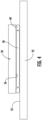
- the surface 52 of the heat exchanger 20 configured to receive the power electronics module 50 is generally planar (see FIG. 4 ). As a result, the entirety of the gasket 60 is positioned adjacent to and in overlapping arrangement with the surface 52.
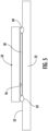
- a gasket groove or recess 62 complementary to the gasket 60 is formed in the surface 52 of the heat exchanger 20. In such embodiments, the gasket 60 is receivable within the gasket groove 62, and therefore only a portion of the gasket 60 protrudes beyond the surface 52 towards the power electronics module 50.
- the gasket 60 When the power electronics module 50 is installed about the surface 52 of the heat exchanger 20, the gasket 60 may be at least partially compressed, thereby forming a seal between the surface 52 of the heat exchanger 20 and a surface of the power electronics module 50 at the heat sink interface 56. Because the gasket 60 extends about at least a portion of the periphery of the heat sink interface 56, the gasket forms a boundary or outer edge to at least a portion of the thermal interface material 58. Accordingly, the seal formed between the power electronics module 50 and the surface 52 of the heat exchanger 20 by the compressed gaskets 60 forms a boundary that restricts movement of the thermal interface material 58 from adjacent to the heat sink interface 56.
- the thermal conductivity between the power electronics module 50 and the heat exchanger 20 is improved, thereby extending the life of the electronic components within the power electronics modules 50.
Landscapes
- Engineering & Computer Science (AREA)
- Microelectronics & Electronic Packaging (AREA)
- Physics & Mathematics (AREA)
- Thermal Sciences (AREA)
- Cooling Or The Like Of Electrical Apparatus (AREA)
- Cooling Or The Like Of Semiconductors Or Solid State Devices (AREA)
Abstract
Description
- The present invention relates to a heat exchange assembly. Exemplary embodiments pertain to the art of heat exchangers, and more particularly to an interface for cooling power electronics that are mounted to a heat exchanger.
- Power electronic devices such as motor drives can generate waste heat during operation based on the efficiency of the device. Additionally, when the power electronic devices heat up, their efficiency can degrade adding to the amount of heat they generate. When configured into a refrigeration system, effective thermal integration of these devices can be important aspect to the system's overall efficiency and reliability. Consequently, a goal of the system integrator is to maintain these components within a range of operating temperatures which will maximize the system efficiency. Accordingly, there remains a need in the art for heat exchangers configured to closely integrate with power electronic devices which can maintain optimal temperatures for these components under a variety of load conditions.
- Viewed from a first aspect, there is provided a heat exchanger assembly includes a heat exchanger and a power electronics module mounted to the heat exchanger. The power electronics module is thermally coupled to the heat exchanger at a heat sink interface. A thermal interface material is arranged between the heat sink interface and a surface of the heat exchanger and a gasket arranged between the heat sink interface and the surface of the heat exchanger.
- The gasket may surround at least a portion of the thermal interface material.
- The gasket may define a boundary that restricts movement of the thermal interface material relative to the heat sink interface and the surface of the heat exchanger.
- The gasket may extend about at least a portion of a periphery of the heat sink interface.
- The gasket may extend about an entire periphery of the heat sink interface.
- The gasket may be compressed to form a seal between the heat sink interface and the surface of the heat exchanger.
- The surface of the heat exchanger may have a substantially planar configuration and the gasket is positioned in overlapping arrangement with the surface.
- The surface of the heat exchanger may have a gasket groove formed therein, the gasket being arranged within the gasket groove.
- Only a portion of the gasket may extend beyond the surface of the heat exchanger.
- The gasket may have a substantially continuous tube-like configuration.
- The gasket may have a substantially planar configuration.
- The thermal interface material may be thermal grease.
- The power electronics module may be mounted in a vertical plane.
- The heat exchanger may comprise: a housing having an inlet and an outlet formed therein; a fluid circuit arranged within the housing and extending between the inlet and the outlet; and a fluid circulating through the fluid circuit.
- The fluid circuit may comprise: an inlet manifold; an outlet manifold; and a plurality of fluid passages connecting the inlet manifold and the outlet manifold.
- At least one of the inlet manifold, the outlet manifold, and the plurality of fluid passages may be formed as a recess formed in the housing.
- The inlet may be disposed below the outlet such that during operation a flow direction of a refrigerant through the inlet manifold and the outlet manifold opposes gravity.
- The housing may comprise a first housing portion and a second housing portion joined along corresponding mating surfaces.
- The first housing portion and the second housing portion may be a plate.
- The following descriptions should not be considered limiting in any way. With reference to the accompanying drawings, like elements are numbered alike:
-
FIG. 1 is a schematic illustration of an exemplary heat exchanger having a power electronic modules mounted thereto; -
FIG. 2 is a schematic illustrations of the A-A cross section of the heat exchanger ofFIG. 1 ; -
FIG. 3 is a front view of an exemplary heat exchanger having a plurality to of power electronic modules mounted thereto; -
FIG. 4 is a cross-sectional view of a portion of the heat exchanger ofFIG. 3 taken through a power electronic module; and -
FIG. 5 is a cross-sectional view of a portion of the heat exchanger ofFIG. 3 taken through a power electronic module. - A detailed description of one or more embodiments of the disclosed apparatus and method are presented herein by way of exemplification and not limitation with reference to the Figures.
- With reference now to
Figure 1 , a schematic illustration of an example of aheat exchanger 20 is illustrated according to an embodiment. As shown, theheat exchanger 20 includes ahousing 22 formed from a heat conductive material, such as a metal material. For example, thehousing 22 may be formed from any suitable metal, e.g., aluminum, aluminum alloy, steel, steel alloy, copper, copper alloy, or the like. In the illustrated, non-limiting embodiment, thehousing 22 is formed from a plurality of housing portions, such as afirst housing portion 24, and asecond housing portion 26, joined along corresponding mating surfaces to form aseam 28 therebetween. In such embodiments, the first andsecond housing portions housing portions housing 22 formed from any number of housing portions including a single housing portion, or more than two housing portions for example, are contemplated. - The mating surfaces of the first and
second housing portions second housing portions second housing portions - As shown in
Fig. 1 , the first andsecond housing portions first housing portion 24 is greater than a thickness of the second housing portion. However, embodiments where thefirst housing portion 24 and thesecond housing portion 26 are equal in thickness, or alternatively, where a thickness of thesecond housing portion 26 is greater than a thickness of thefirst housing portion 24 are also contemplated. In an embodiment, each of thefirst housing portion 24 and thesecond housing portion 26 is formed as a substantially solid plate. However, embodiments where one or more of thehousing portions - The
heat exchanger 20 includes a fluid circuit formed between the first andsecond housing portions fluid inlet 30 andfluid outlet 32 formed in thehousing 22. Thefluid inlet 30 and thefluid outlet 32 can be any shape, such as in the depth dimension (e.g., in the z-x plane of the attached figure), including the shape of a circle, oval, triangular, square, rectangular, or any simple polygonal shape or portion thereof. Further, the perimeter of one or both of the fluid inlet 30 and thefluid outlet 32 can be formed by a recess in at least one or both of thehousing portions seam 28 defined between twoadjacent housing portions - An example of the fluid circuit is best illustrated in the cross-sectional view of the
heat exchanger 20 shown inFIG. 2 . In addition to theinlet 30 and theoutlet 32, the fluid circuit may include a first orinlet manifold 34, a second oroutlet manifold 36, and a plurality offluid passages 38 connecting the first andsecond manifolds fluid inlet 30 can be configured to connect a first heat transfer fluid (e.g., refrigerant) source, such as a condenser of a vapor compression system for example, to the inlet manifold using any suitable mechanical connection. Similarly, thefluid outlet 32 can be configured to connect a first heat transfer fluid sink, such as an evaporator of a vapor compression system for example, to the outlet manifold using any suitable mechanical connection (e.g., compression coupling, brazing, welding, and the like). In an embodiment, thefluid inlet 30 is disposed vertically below thefluid outlet 32 such that during operation of theheat exchanger 20, a flow direction of a refrigerant through the inlet andoutlet manifolds - One or more of the
inlet manifold 34, the outlet manifold 36, and the plurality offluid passages 38 is formed as a recess in at least one of thefirst housing portion 24 and thesecond housing portion 26. In an embodiment, the inlet manifold 34, the outlet manifold 36, and the plurality offluid passages 38 are formed as a plurality of connected recesses in at least one housing portion, such as thesecond housing portion 26 for example. Accordingly, the plurality of recesses form the fluid circuit disposed between the first andsecond housing portions housing portions first housing portion 24 having a plurality of connected recesses can be joined to a flat,second housing portion 26 that does not have any recesses formed therein. In another embodiment, afirst housing portion 24 and asecond housing portion 26 can each have a plurality of connected recesses which mirror one another such that when the first andsecond housing portions - The mating surfaces of the first and
second housing portions housing portions - A
heat exchanger 20 as described herein can be used, such as in a vapor compression system for example, to cool one or more powerelectronic modules 50. As described herein, aheat exchanger 20 having one or morepower electronics modules 50 mounted thereon may be considered a heat exchanger assembly. The term "power electronic module" as used herein can refer to any electronic component which can provide a controlled output power by modulating and/or converting a supplied input power (e.g., a variable frequency drive, power rectifier, power converter, and the like). Such a powerelectronic module 50 can be used to control the speed of a compressor and/or the speed of the fan of a vapor compression system (e.g., chiller) based on various predetermined system conditions. With reference again toFIG. 1 , and further reference toFIGS. 3-5 , in an embodiment, one or more powerelectronic modules 50 are mounted directly to asurface 52 of at least one of the plurality of housing portions, such asfirst housing portion 24 for example. In the illustrated, non-limiting embodiment, the plurality ofpower electronics modules 50 are mounted to a vertically oriented surface of thehousing 22. However, embodiments where one or morepower electronics modules 50 are mounted to a surface of ahousing 22 having a non-vertical orientation, such as a horizontal surface for example, are also contemplated. The powerelectronic modules 50 may be mounted to thehousing 22 of theheat exchanger 20 via one or more fasteners in such a way that facilitates the transfer of thermal energy away from thepower electronics module 50. - The one or more
power electronics modules 50 may include a printedcircuit board 54 on which various other electrical components (not shown) are mounted (e.g., protection, signal processing, and filtering related components). The reliability and life of the one or morepower electronics modules 50 can depend upon precluding such electrical components from operating at high temperatures and/or precluding their exposure to thermal shock. Because electrical components inside thepower electronics modules 50 can generate a large amount of heat, each of thepower electronics modules 50 has a heat sink interface 56 (seeFIG. 4 ) which is designed for attachment to a heat sink, such as theheat exchanger 20. When thepower electronics modules 50 are secured in thermal communication with theheat exchanger 20, the heat generated by thepower electronics module 50 is at least partially removed through theheat sink interface 56 to keep the one or morepower electronics module 50 cooled below its maximum allowable operating temperature (e.g., 150 °C). - A thermal interface material, illustrated schematically at 58, may be positioned between the
heat sink interface 56 of a respectivepower electronics module 50 and theadjacent surface 52 of thehousing 22 configured to receive thepower electronics module 50. In an embodiment, thethermal interface material 58 is a thermal grease or compound having a high thermal conductivity. However, in other embodiments the thermal interface material may include a multiphase material and/or an elastomeric material such as a thermal pad. In applications where apower electronics module 50 is mounted in a vertical plane relative to asurface 52 of thehousing 22 of theheat exchanger 20, the gravitational forces acting on thethermal grease 58 may cause thethermal grease 58 to move or drip relative to theheat sink interface 56. In addition, if condensation collects on thesurface 52 of theheat exchanger 20, such as resulting from the heat removal therefrom, the condensation in combination with the gravitational forces may wash thethermal grease 58 away from theheat sink interface 56. - In an embodiment, to prevent this loss or washing away of the
thermal interface material 58 at theheat sink interface 56, agasket 60 is disposed between a portion of thepower electronics module 50 and theheat exchanger 20. Thegasket 60 may extend about at least a portion of the perimeter of thepower electronics module 50 at theheat sink interface 56. In the illustrated, non-limiting embodiment, thegasket 60 extends about an entire periphery of theheat sink interface 56. In such embodiments, the dimensions of thegasket 60 are substantially complementary to, or slightly smaller than, the length and width of a respectivepower electronics module 50. Thegasket 60 may have a substantially continuous tube-like configuration, or alternatively, may have a substantially planar configuration similar to a washer. However, any suitable configuration of agasket 60 is contemplated. - In an embodiment, the
surface 52 of theheat exchanger 20 configured to receive thepower electronics module 50 is generally planar (seeFIG. 4 ). As a result, the entirety of thegasket 60 is positioned adjacent to and in overlapping arrangement with thesurface 52. In another embodiment, best shown inFIG. 5 , a gasket groove orrecess 62 complementary to thegasket 60 is formed in thesurface 52 of theheat exchanger 20. In such embodiments, thegasket 60 is receivable within thegasket groove 62, and therefore only a portion of thegasket 60 protrudes beyond thesurface 52 towards thepower electronics module 50. - When the
power electronics module 50 is installed about thesurface 52 of theheat exchanger 20, thegasket 60 may be at least partially compressed, thereby forming a seal between thesurface 52 of theheat exchanger 20 and a surface of thepower electronics module 50 at theheat sink interface 56. Because thegasket 60 extends about at least a portion of the periphery of theheat sink interface 56, the gasket forms a boundary or outer edge to at least a portion of thethermal interface material 58. Accordingly, the seal formed between thepower electronics module 50 and thesurface 52 of theheat exchanger 20 by thecompressed gaskets 60 forms a boundary that restricts movement of thethermal interface material 58 from adjacent to theheat sink interface 56. - By using a gasket to retain the
thermal interface material 58 between theheat sink interface 56 of apower electronics module 50 and aheat exchanger 20, the thermal conductivity between thepower electronics module 50 and theheat exchanger 20 is improved, thereby extending the life of the electronic components within thepower electronics modules 50. - The terminology used herein is for the purpose of describing particular embodiments only and is not intended to be limiting of the present disclosure. As used herein, the singular forms "a", "an" and "the" are intended to include the plural forms as well, unless the context clearly indicates otherwise. It will be further understood that the terms "comprises" and/or "comprising," when used in this specification, specify the presence of stated features, integers, steps, operations, elements, and/or components, but do not preclude the presence or addition of one or more other features, integers, steps, operations, element components, and/or groups thereof.
- While the present invention has been described with reference to an exemplary embodiment or embodiments, it will be understood by those skilled in the art that various changes may be made and equivalents may be substituted for elements thereof without departing from the scope of the present invention as defined by the appended claims. In addition, many modifications may be made to adapt a particular situation or material to the teachings of the present invention without departing from the scope of the claims. Therefore, it is intended that the present invention not be limited to the particular embodiment disclosed as the best mode contemplated for carrying out this present invention, but that the present invention will include all embodiments falling within the scope of the claims.
Claims (15)
- A heat exchanger assembly comprising:a heat exchanger (20);a power electronics module (50) mounted to the heat exchanger (20), wherein the power electronics module (50) is thermally coupled to the heat exchanger (20) at a heat sink interface (56);a thermal interface material (58) arranged between the heat sink interface (56) and a surface (52) of the heat exchanger (20); anda gasket (60) arranged between the heat sink interface (56) and the surface (52) of the heat exchanger (50).
- The heat exchanger assembly of claim 1, wherein the gasket (60) surrounds at least a portion of the thermal interface material (58).
- The heat exchanger assembly of claim 1 or 2, wherein the gasket (60) defines a boundary that restricts movement of the thermal interface material (58) relative to the heat sink interface (56) and the surface (52) of the heat exchanger (20).
- The heat exchanger assembly of claim 1, 2 or 3, wherein the gasket (60) extends about at least a portion of a periphery of the heat sink interface (56).
- The heat exchanger assembly of claim 4, wherein the gasket (60) extends about an entire periphery of the heat sink interface (56).
- The heat exchanger assembly of any preceding claim, wherein the gasket (60) is compressed to form a seal between the heat sink interface (56) and the surface (52) of the heat exchanger (20).
- The heat exchanger assembly of any preceding claim, wherein the surface (52) of the heat exchanger (20) has a substantially planar configuration and the gasket (60) is positioned in overlapping arrangement with the surface (52).
- The heat exchanger assembly of any of claims 1 to 6, wherein the surface (52) of the heat exchanger (20) has a gasket groove (62) formed therein, the gasket (60) being arranged within the gasket groove (62).
- The heat exchanger assembly of claim 8, wherein only a portion of the gasket (20) extends beyond the surface (52) of the heat exchanger (20).
- The heat exchanger assembly of any preceding claim, wherein the gasket (60) has a substantially continuous tube-like configuration;
or
wherein the gasket (60) has a substantially planar configuration. - The heat exchanger assembly of any preceding claim, wherein the thermal interface material (58) is thermal grease;
and/or
wherein the power electronics module (50) is mounted in a vertical plane. - The heat exchanger assembly of any preceding claim, wherein the heat exchanger (20) further comprises:a housing (22) having an inlet (30) and an outlet (32) formed therein;a fluid circuit arranged within the housing (22) and extending between the inlet (30) and the outlet (32); anda fluid circulating through the fluid circuit.
- The heat exchanger assembly of claim 12, wherein the fluid circuit further comprises:an inlet manifold (34);an outlet manifold (36); anda plurality of fluid passages (38) connecting the inlet manifold (34) and the outlet manifold (36).
- The heat exchanger assembly of claim 13, wherein at least one of the inlet manifold (34), the outlet manifold (36), and the plurality of fluid passages (38) is formed as a recess formed in the housing (22);
and/or
wherein the inlet (30) is disposed below the outlet (32) such that during operation a flow direction of a refrigerant through the inlet manifold (34) and the outlet manifold (36) opposes gravity. - The heat exchanger assembly of claim 12, 13 or 14, wherein the housing (22) further comprises a first housing portion (24) and a second housing portion (26) joined along corresponding mating surfaces;
optionally wherein at least one of the first housing portion (24) and the second housing portion (26) is a plate.
Applications Claiming Priority (1)
| Application Number | Priority Date | Filing Date | Title |
|---|---|---|---|
| US202163270888P | 2021-10-22 | 2021-10-22 |
Publications (2)
| Publication Number | Publication Date |
|---|---|
| EP4171185A1 true EP4171185A1 (en) | 2023-04-26 |
| EP4171185B1 EP4171185B1 (en) | 2025-08-20 |
Family
ID=83899824
Family Applications (1)
| Application Number | Title | Priority Date | Filing Date |
|---|---|---|---|
| EP22202611.4A Active EP4171185B1 (en) | 2021-10-22 | 2022-10-19 | Seal for thermal interface material of power electronics modules |
Country Status (3)
| Country | Link |
|---|---|
| US (1) | US20230127088A1 (en) |
| EP (1) | EP4171185B1 (en) |
| CN (1) | CN116017930A (en) |
Citations (3)
| Publication number | Priority date | Publication date | Assignee | Title |
|---|---|---|---|---|
| JP2010092999A (en) * | 2008-10-07 | 2010-04-22 | Toyota Motor Corp | Heat dissipation structure and inverter for vehicle |
| US8077460B1 (en) * | 2010-07-19 | 2011-12-13 | Toyota Motor Engineering & Manufacturing North America, Inc. | Heat exchanger fluid distribution manifolds and power electronics modules incorporating the same |
| US20160240456A1 (en) * | 2013-12-27 | 2016-08-18 | Mitsubishi Electric Corporation | Semiconductor device |
Family Cites Families (5)
| Publication number | Priority date | Publication date | Assignee | Title |
|---|---|---|---|---|
| US7369411B2 (en) * | 2000-02-25 | 2008-05-06 | Thermagon, Inc. | Thermal interface assembly and method for forming a thermal interface between a microelectronic component package and heat sink |
| US7554190B2 (en) * | 2004-12-03 | 2009-06-30 | Chris Macris | Liquid metal thermal interface material system |
| US8232637B2 (en) * | 2009-04-30 | 2012-07-31 | General Electric Company | Insulated metal substrates incorporating advanced cooling |
| WO2016103678A1 (en) * | 2014-12-24 | 2016-06-30 | パナソニックIpマネジメント株式会社 | Simple inverter-control-type refrigerator, inverter control unit for refrigerator, and inverter compressor using same |
| US11193722B2 (en) * | 2018-05-01 | 2021-12-07 | Dana Canada Corporation | Heat exchanger with multi-zone heat transfer surface |
-
2022
- 2022-10-07 US US17/961,694 patent/US20230127088A1/en active Pending
- 2022-10-19 EP EP22202611.4A patent/EP4171185B1/en active Active
- 2022-10-21 CN CN202211291639.0A patent/CN116017930A/en active Pending
Patent Citations (3)
| Publication number | Priority date | Publication date | Assignee | Title |
|---|---|---|---|---|
| JP2010092999A (en) * | 2008-10-07 | 2010-04-22 | Toyota Motor Corp | Heat dissipation structure and inverter for vehicle |
| US8077460B1 (en) * | 2010-07-19 | 2011-12-13 | Toyota Motor Engineering & Manufacturing North America, Inc. | Heat exchanger fluid distribution manifolds and power electronics modules incorporating the same |
| US20160240456A1 (en) * | 2013-12-27 | 2016-08-18 | Mitsubishi Electric Corporation | Semiconductor device |
Also Published As
| Publication number | Publication date |
|---|---|
| EP4171185B1 (en) | 2025-08-20 |
| US20230127088A1 (en) | 2023-04-27 |
| CN116017930A (en) | 2023-04-25 |
Similar Documents
| Publication | Publication Date | Title |
|---|---|---|
| CN118891598B (en) | Active cooling heat sink cover for computer processor and processor assembly | |
| US10724748B2 (en) | Air-conditioning apparatus | |
| EP0107706B1 (en) | Heat pipe cooling module for high power circuit boards | |
| US9897383B2 (en) | Heat exchanger | |
| US10837720B2 (en) | Heat exchanger with aluminum tubes rolled into an aluminum tube support | |
| EP4175436A1 (en) | Refrigerant cooled heat sink for power electronic modules | |
| WO2015102546A1 (en) | A liquid cooled device enclosure | |
| WO2011009412A1 (en) | Heat exchanger assembly and machine using the same | |
| CN114727544A (en) | Cooling device and method for manufacturing the same | |
| WO2014065696A1 (en) | Computer module cooler | |
| EP4171185B1 (en) | Seal for thermal interface material of power electronics modules | |
| EP3396211A1 (en) | Cooling device for components of wind turbines | |
| EP4175434A1 (en) | Combined liquid and air cooled power electronics assembly | |
| CN222187170U (en) | Variable frequency electric control device, outdoor unit and heating and ventilation equipment | |
| RU125757U1 (en) | COOLER OF COMPUTER COMPUTER MODULES | |
| EP4093169B1 (en) | Heat exchanger for power electronics | |
| US12042890B2 (en) | Method for manufacturing a heat sink | |
| RU2179768C2 (en) | Thermoelectric module | |
| EP3575919A1 (en) | Dlc block for use in electronic and electric components | |
| EP3396288A1 (en) | Refrigeration device for a power converter | |
| CN221944351U (en) | Air conditioner outdoor unit | |
| EP4174433B1 (en) | Heating ventilation and air conditioning system with heat exchanger for power electronics | |
| KR102923440B1 (en) | Cooling channel insertion type semiconductor package module | |
| EP4398691A1 (en) | Cooling system for power electronics | |
| CN224265324U (en) | Water cooling heat dissipation device |
Legal Events
| Date | Code | Title | Description |
|---|---|---|---|
| PUAI | Public reference made under article 153(3) epc to a published international application that has entered the european phase |
Free format text: ORIGINAL CODE: 0009012 |
|
| STAA | Information on the status of an ep patent application or granted ep patent |
Free format text: STATUS: THE APPLICATION HAS BEEN PUBLISHED |
|
| AK | Designated contracting states |
Kind code of ref document: A1 Designated state(s): AL AT BE BG CH CY CZ DE DK EE ES FI FR GB GR HR HU IE IS IT LI LT LU LV MC ME MK MT NL NO PL PT RO RS SE SI SK SM TR |
|
| P01 | Opt-out of the competence of the unified patent court (upc) registered |
Effective date: 20230527 |
|
| STAA | Information on the status of an ep patent application or granted ep patent |
Free format text: STATUS: REQUEST FOR EXAMINATION WAS MADE |
|
| 17P | Request for examination filed |
Effective date: 20231025 |
|
| RBV | Designated contracting states (corrected) |
Designated state(s): AL AT BE BG CH CY CZ DE DK EE ES FI FR GB GR HR HU IE IS IT LI LT LU LV MC ME MK MT NL NO PL PT RO RS SE SI SK SM TR |
|
| STAA | Information on the status of an ep patent application or granted ep patent |
Free format text: STATUS: EXAMINATION IS IN PROGRESS |
|
| 17Q | First examination report despatched |
Effective date: 20240208 |
|
| GRAP | Despatch of communication of intention to grant a patent |
Free format text: ORIGINAL CODE: EPIDOSNIGR1 |
|
| STAA | Information on the status of an ep patent application or granted ep patent |
Free format text: STATUS: GRANT OF PATENT IS INTENDED |
|
| INTG | Intention to grant announced |
Effective date: 20250317 |
|
| GRAS | Grant fee paid |
Free format text: ORIGINAL CODE: EPIDOSNIGR3 |
|
| GRAA | (expected) grant |
Free format text: ORIGINAL CODE: 0009210 |
|
| STAA | Information on the status of an ep patent application or granted ep patent |
Free format text: STATUS: THE PATENT HAS BEEN GRANTED |
|
| AK | Designated contracting states |
Kind code of ref document: B1 Designated state(s): AL AT BE BG CH CY CZ DE DK EE ES FI FR GB GR HR HU IE IS IT LI LT LU LV MC ME MK MT NL NO PL PT RO RS SE SI SK SM TR |
|
| REG | Reference to a national code |
Ref country code: GB Ref legal event code: FG4D |
|
| REG | Reference to a national code |
Ref country code: CH Ref legal event code: EP |
|
| REG | Reference to a national code |
Ref country code: IE Ref legal event code: FG4D Ref country code: NL Ref legal event code: FP |
|
| REG | Reference to a national code |
Ref country code: DE Ref legal event code: R096 Ref document number: 602022019728 Country of ref document: DE |
|
| PGFP | Annual fee paid to national office [announced via postgrant information from national office to epo] |
Ref country code: NL Payment date: 20250923 Year of fee payment: 4 |
|
| PGFP | Annual fee paid to national office [announced via postgrant information from national office to epo] |
Ref country code: FR Payment date: 20250924 Year of fee payment: 4 |
|
| PG25 | Lapsed in a contracting state [announced via postgrant information from national office to epo] |
Ref country code: IS Free format text: LAPSE BECAUSE OF FAILURE TO SUBMIT A TRANSLATION OF THE DESCRIPTION OR TO PAY THE FEE WITHIN THE PRESCRIBED TIME-LIMIT Effective date: 20251220 |
|
| PGFP | Annual fee paid to national office [announced via postgrant information from national office to epo] |
Ref country code: DE Payment date: 20250923 Year of fee payment: 4 |
|
| PG25 | Lapsed in a contracting state [announced via postgrant information from national office to epo] |
Ref country code: NO Free format text: LAPSE BECAUSE OF FAILURE TO SUBMIT A TRANSLATION OF THE DESCRIPTION OR TO PAY THE FEE WITHIN THE PRESCRIBED TIME-LIMIT Effective date: 20251120 |
|
| REG | Reference to a national code |
Ref country code: LT Ref legal event code: MG9D |
|
| PG25 | Lapsed in a contracting state [announced via postgrant information from national office to epo] |
Ref country code: PT Free format text: LAPSE BECAUSE OF FAILURE TO SUBMIT A TRANSLATION OF THE DESCRIPTION OR TO PAY THE FEE WITHIN THE PRESCRIBED TIME-LIMIT Effective date: 20251222 |
|
| PG25 | Lapsed in a contracting state [announced via postgrant information from national office to epo] |
Ref country code: FI Free format text: LAPSE BECAUSE OF FAILURE TO SUBMIT A TRANSLATION OF THE DESCRIPTION OR TO PAY THE FEE WITHIN THE PRESCRIBED TIME-LIMIT Effective date: 20250820 |
|
| PG25 | Lapsed in a contracting state [announced via postgrant information from national office to epo] |
Ref country code: HR Free format text: LAPSE BECAUSE OF FAILURE TO SUBMIT A TRANSLATION OF THE DESCRIPTION OR TO PAY THE FEE WITHIN THE PRESCRIBED TIME-LIMIT Effective date: 20250820 |
|
| PG25 | Lapsed in a contracting state [announced via postgrant information from national office to epo] |
Ref country code: GR Free format text: LAPSE BECAUSE OF FAILURE TO SUBMIT A TRANSLATION OF THE DESCRIPTION OR TO PAY THE FEE WITHIN THE PRESCRIBED TIME-LIMIT Effective date: 20251121 |
|
| PG25 | Lapsed in a contracting state [announced via postgrant information from national office to epo] |
Ref country code: SE Free format text: LAPSE BECAUSE OF FAILURE TO SUBMIT A TRANSLATION OF THE DESCRIPTION OR TO PAY THE FEE WITHIN THE PRESCRIBED TIME-LIMIT Effective date: 20250820 |
|
| PG25 | Lapsed in a contracting state [announced via postgrant information from national office to epo] |
Ref country code: LV Free format text: LAPSE BECAUSE OF FAILURE TO SUBMIT A TRANSLATION OF THE DESCRIPTION OR TO PAY THE FEE WITHIN THE PRESCRIBED TIME-LIMIT Effective date: 20250820 |
|
| PG25 | Lapsed in a contracting state [announced via postgrant information from national office to epo] |
Ref country code: BG Free format text: LAPSE BECAUSE OF FAILURE TO SUBMIT A TRANSLATION OF THE DESCRIPTION OR TO PAY THE FEE WITHIN THE PRESCRIBED TIME-LIMIT Effective date: 20250820 Ref country code: PL Free format text: LAPSE BECAUSE OF FAILURE TO SUBMIT A TRANSLATION OF THE DESCRIPTION OR TO PAY THE FEE WITHIN THE PRESCRIBED TIME-LIMIT Effective date: 20250820 |
|
| PG25 | Lapsed in a contracting state [announced via postgrant information from national office to epo] |
Ref country code: RS Free format text: LAPSE BECAUSE OF FAILURE TO SUBMIT A TRANSLATION OF THE DESCRIPTION OR TO PAY THE FEE WITHIN THE PRESCRIBED TIME-LIMIT Effective date: 20251120 |
|
| PG25 | Lapsed in a contracting state [announced via postgrant information from national office to epo] |
Ref country code: ES Free format text: LAPSE BECAUSE OF FAILURE TO SUBMIT A TRANSLATION OF THE DESCRIPTION OR TO PAY THE FEE WITHIN THE PRESCRIBED TIME-LIMIT Effective date: 20250820 |
|
| REG | Reference to a national code |
Ref country code: AT Ref legal event code: MK05 Ref document number: 1828809 Country of ref document: AT Kind code of ref document: T Effective date: 20250820 |
|
| PG25 | Lapsed in a contracting state [announced via postgrant information from national office to epo] |
Ref country code: RO Free format text: LAPSE BECAUSE OF FAILURE TO SUBMIT A TRANSLATION OF THE DESCRIPTION OR TO PAY THE FEE WITHIN THE PRESCRIBED TIME-LIMIT Effective date: 20250820 |
|
| PG25 | Lapsed in a contracting state [announced via postgrant information from national office to epo] |
Ref country code: SM Free format text: LAPSE BECAUSE OF FAILURE TO SUBMIT A TRANSLATION OF THE DESCRIPTION OR TO PAY THE FEE WITHIN THE PRESCRIBED TIME-LIMIT Effective date: 20250820 |
|
| PG25 | Lapsed in a contracting state [announced via postgrant information from national office to epo] |
Ref country code: DK Free format text: LAPSE BECAUSE OF FAILURE TO SUBMIT A TRANSLATION OF THE DESCRIPTION OR TO PAY THE FEE WITHIN THE PRESCRIBED TIME-LIMIT Effective date: 20250820 |
|
| PG25 | Lapsed in a contracting state [announced via postgrant information from national office to epo] |
Ref country code: AT Free format text: LAPSE BECAUSE OF FAILURE TO SUBMIT A TRANSLATION OF THE DESCRIPTION OR TO PAY THE FEE WITHIN THE PRESCRIBED TIME-LIMIT Effective date: 20250820 |
|
| PG25 | Lapsed in a contracting state [announced via postgrant information from national office to epo] |
Ref country code: IT Free format text: LAPSE BECAUSE OF FAILURE TO SUBMIT A TRANSLATION OF THE DESCRIPTION OR TO PAY THE FEE WITHIN THE PRESCRIBED TIME-LIMIT Effective date: 20250820 |
|
| PG25 | Lapsed in a contracting state [announced via postgrant information from national office to epo] |
Ref country code: CZ Free format text: LAPSE BECAUSE OF FAILURE TO SUBMIT A TRANSLATION OF THE DESCRIPTION OR TO PAY THE FEE WITHIN THE PRESCRIBED TIME-LIMIT Effective date: 20250820 |
|
| PG25 | Lapsed in a contracting state [announced via postgrant information from national office to epo] |
Ref country code: EE Free format text: LAPSE BECAUSE OF FAILURE TO SUBMIT A TRANSLATION OF THE DESCRIPTION OR TO PAY THE FEE WITHIN THE PRESCRIBED TIME-LIMIT Effective date: 20250820 Ref country code: SK Free format text: LAPSE BECAUSE OF FAILURE TO SUBMIT A TRANSLATION OF THE DESCRIPTION OR TO PAY THE FEE WITHIN THE PRESCRIBED TIME-LIMIT Effective date: 20250820 |