EP4171009A1 - Anti-shake camera and terminal - Google Patents
Anti-shake camera and terminal Download PDFInfo
- Publication number
- EP4171009A1 EP4171009A1 EP21828539.3A EP21828539A EP4171009A1 EP 4171009 A1 EP4171009 A1 EP 4171009A1 EP 21828539 A EP21828539 A EP 21828539A EP 4171009 A1 EP4171009 A1 EP 4171009A1
- Authority
- EP
- European Patent Office
- Prior art keywords
- fixing plate
- fan
- coil fixing
- substrate
- areas
- Prior art date
- Legal status (The legal status is an assumption and is not a legal conclusion. Google has not performed a legal analysis and makes no representation as to the accuracy of the status listed.)
- Granted
Links
Images


Classifications
-
- H—ELECTRICITY
- H04—ELECTRIC COMMUNICATION TECHNIQUE
- H04N—PICTORIAL COMMUNICATION, e.g. TELEVISION
- H04N23/00—Cameras or camera modules comprising electronic image sensors; Control thereof
- H04N23/50—Constructional details
-
- H—ELECTRICITY
- H04—ELECTRIC COMMUNICATION TECHNIQUE
- H04N—PICTORIAL COMMUNICATION, e.g. TELEVISION
- H04N23/00—Cameras or camera modules comprising electronic image sensors; Control thereof
- H04N23/50—Constructional details
- H04N23/54—Mounting of pick-up tubes, electronic image sensors, deviation or focusing coils
-
- H—ELECTRICITY
- H04—ELECTRIC COMMUNICATION TECHNIQUE
- H04N—PICTORIAL COMMUNICATION, e.g. TELEVISION
- H04N23/00—Cameras or camera modules comprising electronic image sensors; Control thereof
- H04N23/50—Constructional details
- H04N23/51—Housings
-
- H—ELECTRICITY
- H04—ELECTRIC COMMUNICATION TECHNIQUE
- H04N—PICTORIAL COMMUNICATION, e.g. TELEVISION
- H04N23/00—Cameras or camera modules comprising electronic image sensors; Control thereof
- H04N23/50—Constructional details
- H04N23/55—Optical parts specially adapted for electronic image sensors; Mounting thereof
-
- H—ELECTRICITY
- H04—ELECTRIC COMMUNICATION TECHNIQUE
- H04N—PICTORIAL COMMUNICATION, e.g. TELEVISION
- H04N23/00—Cameras or camera modules comprising electronic image sensors; Control thereof
- H04N23/57—Mechanical or electrical details of cameras or camera modules specially adapted for being embedded in other devices
-
- H—ELECTRICITY
- H04—ELECTRIC COMMUNICATION TECHNIQUE
- H04N—PICTORIAL COMMUNICATION, e.g. TELEVISION
- H04N23/00—Cameras or camera modules comprising electronic image sensors; Control thereof
- H04N23/60—Control of cameras or camera modules
- H04N23/68—Control of cameras or camera modules for stable pick-up of the scene, e.g. compensating for camera body vibrations
-
- H—ELECTRICITY
- H04—ELECTRIC COMMUNICATION TECHNIQUE
- H04N—PICTORIAL COMMUNICATION, e.g. TELEVISION
- H04N23/00—Cameras or camera modules comprising electronic image sensors; Control thereof
- H04N23/60—Control of cameras or camera modules
- H04N23/68—Control of cameras or camera modules for stable pick-up of the scene, e.g. compensating for camera body vibrations
- H04N23/682—Vibration or motion blur correction
- H04N23/685—Vibration or motion blur correction performed by mechanical compensation
-
- H—ELECTRICITY
- H04—ELECTRIC COMMUNICATION TECHNIQUE
- H04N—PICTORIAL COMMUNICATION, e.g. TELEVISION
- H04N23/00—Cameras or camera modules comprising electronic image sensors; Control thereof
- H04N23/60—Control of cameras or camera modules
- H04N23/68—Control of cameras or camera modules for stable pick-up of the scene, e.g. compensating for camera body vibrations
- H04N23/682—Vibration or motion blur correction
- H04N23/685—Vibration or motion blur correction performed by mechanical compensation
- H04N23/687—Vibration or motion blur correction performed by mechanical compensation by shifting the lens or sensor position
-
- Y—GENERAL TAGGING OF NEW TECHNOLOGICAL DEVELOPMENTS; GENERAL TAGGING OF CROSS-SECTIONAL TECHNOLOGIES SPANNING OVER SEVERAL SECTIONS OF THE IPC; TECHNICAL SUBJECTS COVERED BY FORMER USPC CROSS-REFERENCE ART COLLECTIONS [XRACs] AND DIGESTS
- Y02—TECHNOLOGIES OR APPLICATIONS FOR MITIGATION OR ADAPTATION AGAINST CLIMATE CHANGE
- Y02B—CLIMATE CHANGE MITIGATION TECHNOLOGIES RELATED TO BUILDINGS, e.g. HOUSING, HOUSE APPLIANCES OR RELATED END-USER APPLICATIONS
- Y02B40/00—Technologies aiming at improving the efficiency of home appliances, e.g. induction cooking or efficient technologies for refrigerators, freezers or dish washers
Definitions
- the embodiments of the present disclosure relate to, but are not limited to, the field of device hardware, and particularly, relate to but are not limited to an anti-shake camera and a terminal.
- a mobile terminal performs photographing and video shooting commonly in a handhold manner, but it is difficult to keep the terminal in a stable state when the user is holding the terminal by hand since the hand is likely to shake, which causes the photos being vague and the videos being formed by shaky images, and as a result, user experience is influenced.
- the current common anti-shake cameras prevent shake in an X-axis and a Y-axis, namely in a left-right direction and an up-down direction of a shooting plane.
- rotary shake namely shake in a Z-axis direction is likely to happen due to reverse movement of two ends of the terminal on the shooting plane besides shake in the left-right direction and the up-down direction.
- shake caused by rotation there is still no proper solution yet.
- the embodiments of the present disclosure provide an anti-shake camera.
- the anti-shake camera includes a camera body, and a circuit board and a coil fixing plate which are fixed to a back surface of the camera body; a back surface of the coil fixing plate is divided into four areas according to diagonal lines, fan-shaped coils are respectively fixed to two symmetric areas among the four areas, and a rotating shaft is arranged in a center of the diagonal lines; a substrate is arranged behind the back surface of the coil fixing plate, a surface, opposite to the back surface of the coil fixing plate, of the substrate is provided with a matching mechanism of the rotating shaft, one or more fan-shaped permanent magnets are fixed to areas, corresponding to areas of the coil fixing plate where no fan-shaped coils are fixed, on the substrate, and gaps with included angles are formed between the one or more fan-shaped permanent magnets and the fan-shaped coils.
- the embodiments of the present disclosure further provide a terminal.
- the terminal includes a terminal body with the above anti-shake camera.
- the embodiments of the present disclosure provide an anti-shake camera and a terminal and mainly solve, by providing the anti-shake camera, the technical problem concerning how to prevent shake in a Z-axis on a shooting plane.
- the terms “install”, “link”, “connect”, “fix” etc. should be generally understood unless specific regulations and limits are provided.
- the scope of these terms includes fixed connection, detachable connection, or integrated connection; mechanical connection or electric connection; direct connection or indirect connection implemented through inter-media; internal communication between two components or interaction relationship between two components.
- the embodiment of the present disclosure provides an anti-shake camera.
- the anti-shake camera includes a camera body, and a circuit board and a coil fixing plate which are fixed to a back surface of the camera body.
- a back surface of the coil fixing plate is divided into four areas according to diagonal lines, fan-shaped coils are respectively fixed to two symmetric areas among the four areas, and a rotating shaft is arranged in a center of the diagonal lines.
- a substrate is arranged behind the back surface of the coil fixing plate, a surface, opposite to the back surface of the coil fixing plate, of the substrate is provided with a matching mechanism of the rotating shaft, one or more fan-shaped permanent magnets are fixed to areas, corresponding to areas of the coil fixing plate where no fan-shaped coils are fixed, on the substrate, and gaps with included angles (included angles of certain values) are formed between the one or more fan-shaped permanent magnets and the fan-shaped coils.
- Fig. 1 is a perspective view of an anti-shake camera according to an embodiment of the present disclosure.
- Fig. 2 is an exploded view 1 of an anti-shake camera according to an embodiment of the present disclosure.
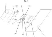
- Fig. 3 is an exploded view 2 of an anti-shake camera according to an embodiment of the present disclosure.
- the anti-shake camera includes a camera body 1, and a circuit board 2 and a coil fixing plate 3 which are fixed to a back surface of the camera body 1, and a substrate 4 is arranged below the coil fixing plate 3.
- the camera body 1, the circuit board 2 and the coil fixing plate 3 are fixed together, and the substrate 4 is movably connected to the coil fixing plate 3.
- the camera body 1 is an imaging assembly of the camera, and mainly includes a protective casing.
- One or more lenses in the protective casing and Complementary Metal Oxide Semiconductors (CMOS) below the one or more lenses are connected to the circuit board 2 and a motherboard through a circuit.
- the circuit board 2 includes a data transmission circuit and a power supply circuit for the camera body 1 and fan-shaped coils 301 on the coil fixing plate 3.
- the coil fixing plate 3 is a main component for driving the circuit board 2 and the camera body 1 to rotate.
- a front surface of the coil fixing plate 3 is fixed to the circuit board 2, a back surface of the coil fixing plate 3 is divided into four areas according to diagonal lines, the fan-shaped coils 301 are respectively fixed to two symmetric areas among the four areas, and electrodes formed after the fan-shaped coil 301 are powered on are distributed at a left end and a right end of the corresponding fan-shaped area.
- the fan-shaped coils 301 are connected to the circuit board 2 through which power is supplied to the fan-shaped coils 301.
- a rotating shaft 302 is arranged at a center of the diagonal lines on the back surface of the coil fixing plate 3, and matched with a matching mechanism 402 on the substrate 4, thereby realizing rotation of the coil fixing plate 3 relative to the substrate 4.
- a center of the substrate 4 corresponds to a center of the coil fixing plate 3, and the matching mechanism 402 matched with the rotating shaft 302 on the coil fixing plate 3 is arranged at the center position to realize rotation.
- One or more fan-shaped permanent magnets 401 are fixed to areas, staggered from the fan-shaped coils 301 of the coil fixing plate 3, on the substrate 4, and magnetic poles of each fan-shaped permanent magnet 401 are distributed at a left end and a right end of a corresponding fan shape.
- Gaps with included angles are formed between the one or more fan-shaped permanent magnets 401 and the left-end and right-end fan-shaped coils 301 after assembling, and the coil fixing plate 3 may rotate within the range of the included angles of the gaps, the larger the included angles of the gaps, the larger the rotating angles are, and the optional rotating angle range includes but not limited to +/-0 degree-20 degrees.
- an interval between the coil fixing plate 3 and the substrate 4 is greater than a thickness of the one or more fan-shaped permanent magnets 401, and is greater than a thickness of the fan-shaped coils 301.
- a reset spring is further arranged between a coil fixing plate and a substrate, one end of the reset spring is fixed to the coil fixing plate, and the other end of the reset spring is fixed to the substrate; and upon a condition that the coil fixing plate rotates relative to the substrate, the reset spring is compressed or stretched.
- a camera body is located at a fixed position upon a condition that fan-shaped coils are not powered on. Referring to Fig. 2 and Fig. 3 , the reference numeral 6 represents the reset spring.
- the reset spring includes two arc springs, and two symmetric spring fixing points are arranged on the back surface of the coil fixing plate.
- the two arc springs are symmetrically arranged on outer sides of the fan-shaped coils and the fan-shaped permanent magnets, middle points of the two arc springs are respectively fixed to the corresponding spring fixing points, and two ends of each of the two arc springs are fixed to the substrate.
- the reset spring 6 includes two arc springs. Meanwhile, the back surface of the coil fixing plate 3 is further provided with spring fixing points 303 capable of fixing the arc springs.
- spring fixing points 303 capable of fixing the arc springs.
- two ends of each arc spring are fixed to the substrate 4, middle points of the arc springs are fixed to the spring fixing points 303. Accordingly, upon a condition that the coil fixing plate 3 rotates, each arc spring is compressed between the middle point and one end of the arc spring, and is stretched between the middle point and the other end of the arc spring; and upon a condition that the fan-shaped coils 301 are powered off, the camera returns to an initial position under the action of the arc springs.
- the coil fixing plate rotates relative to the substrate through a bearing.
- the rotating shaft is a bearing fixing barrel, and the matching mechanism is a bearing fixing column; or the rotating shaft is a bearing fixing column, and the matching mechanism is a bearing fixing barrel.
- the rotating shaft on the back surface of the coil fixing plate 3 is a bearing fixing barrel
- the matching mechanism on the substrate 4 is a bearing fixing column
- the rotating shaft is a bearing fixing column
- the matching mechanism is a bearing fixing barrel
- a circuit board is a Flexible Printed Circuit (FPC).
- FPC Flexible Printed Circuit
- a front surface of the FPC is connected to a circuit of the camera body, and a back surface of the FPC is connected to the fan-shaped coils via through holes in the coil fixing plate.
- the FPC has the characteristics of being thin and good in flexibility and serves as the circuit board in a camera, which can reduce the integral thickness of a camera module.
- Data transmission and power supply of the entire camera module are usually realized by the FPC, thus, the front surface of the FPC is connected to the circuit of the camera body 1 to supply power to the camera body 1 and meanwhile transmit data generated by the camera body 1 in time.
- corresponding through holes are directly formed in the coil fixing plate 3 to facilitate connection between the fan-shaped coils 301 and the FPC, and the back surface of the FPC is directly connected to the fan-shaped coils 301 through the through holes.
- coil connecting columns 201 are arranged on the back surface of the FPC and penetrate through the through holes in the coil fixing plate 3 to be connected to the fan-shaped coils 301.
- one end of the FPC is usually directly packaged and fixed to the entire anti-shake camera module, and the other end of the FPC is connected to a corresponding port of the motherboard in a port manner.
- a circuit, extending out of a camera body, of an FPC is in a right angle form, and the other end of the right angle is reversely folded; and upon a condition that the coil fixing plate rotates, a folding point of the FPC moves along with the rotation of the coil fixing plate.
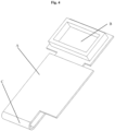
- Fig. 4 is a schematic diagram of a circuit board of an anti-shake camera according to an embodiment of the present disclosure.
- the part, extending out of the camera body, of the PFC is integrally in the right angle form, where the area A is a front surface of the part, extending out of the camera body, of the FPC, the area B is a port in the other end of the FPC and may be directly connected to the motherboard, and the area C is a reverse folding area.
- the circuit will not be damaged by reverse folding since the FPC is made of flexible materials.
- the folding area C follows rotation of the coil fixing plate through front-back movement in the rotating process of the coil fixing plate, thereby preventing the circuit board from interfering with rotation of the coil fixing plate.
- the fan-shaped permanent magnet is arranged in any area in the areas, corresponding to the areas of the coil fixing plate where no fan-shaped coils are fixed, on the substrate, or the fan-shaped permanent magnets are arranged in two areas, corresponding to the areas of the coil fixing plate where no fan-shaped coils are fixed, on the substrate.
- Fig. 2 is a schematic diagram of arranging the fan-shaped permanent magnets in two areas.
- the fan-shaped permanent magnet may be arranged only in one area so as to further reduce a weight of the entire anti-shake camera module.
- the camera body is a zoom camera which is able to prevent shake in an X-axis and a Y-axis. After Z-axis shake prevention is realized, the anti-shake capability of the camera is further enhanced by setting X-axis shake prevention and Y-axis shake prevention on the camera body.
- the camera body, the circuit board, the coil fixing plate and the substrate are packaged on an anti-roll frame, and rotating spaces for the camera body, the circuit board and the coil fixing plate are reserved in the anti-roll frame.
- the camera body, the circuit board, the coil fixing plate and the substrate may be packaged on one anti-roll frame, and meanwhile corresponding movement spaces need to be reserved in the anti-roll frame.
- the embodiments of the present disclosure provide an anti-shake camera.
- the anti-shake camera includes a camera body, and a circuit board and a coil fixing plate which are fixed to a back surface of the camera body; a back surface of the fixing plate is divided into four areas according to diagonal lines, fan-shaped coils are respectively fixed to two symmetric areas among the four areas, and a rotating shaft is arranged in a center of the diagonal lines; and a substrate is arranged behind the back surface of the fixing plate, a surface, opposite to the back surface of the fixing plate, of the substrate is provided with a matching mechanism of the rotating shaft, one or more fan-shaped permanent magnets are fixed to the areas, corresponding to areas of the coil fixing plate where no fan-shaped coils are fixed, on the substrate, and the gaps with included angles are formed between the one or more fan-shaped permanent magnets and the fan-shaped coils.
- the coil fixing plate, the camera body fixed by the coil fixing plate, and the substrate are enabled to rotate through the rotating shaft and the matching mechanism between the coil fixing plate and the substrate, and a rotation angle is controlled by a Micro Control Unit (MCU) through the fan-shaped coils and the permanent magnets.
- MCU Micro Control Unit
- the embodiment of the present disclosure provides a terminal.
- the terminal includes a terminal body with the anti-shake camera according to the embodiments of the present disclosure.
- the anti-shake camera according to the embodiments of the present disclosure may serve as a camera component to be integrated in the terminal, or may also serve as an independent camera shooting module to be externally hung on the exterior of the terminal body.
Landscapes
- Engineering & Computer Science (AREA)
- Multimedia (AREA)
- Signal Processing (AREA)
- Adjustment Of Camera Lenses (AREA)
- Studio Devices (AREA)
- Camera Bodies And Camera Details Or Accessories (AREA)
Abstract
Description
- The present disclosure is based on and claims the benefit of priority of
Chinese patent application No. "202010580877.8" filed on June 23, 2020 - The embodiments of the present disclosure relate to, but are not limited to, the field of device hardware, and particularly, relate to but are not limited to an anti-shake camera and a terminal.
- With the increasing popularity of mobile terminals and smart devices with cameras, more and more people record moments of life by photographing and shooting videos in daily life and meanwhile put forward higher requirements for the quality of photos and videos. A mobile terminal performs photographing and video shooting commonly in a handhold manner, but it is difficult to keep the terminal in a stable state when the user is holding the terminal by hand since the hand is likely to shake, which causes the photos being vague and the videos being formed by shaky images, and as a result, user experience is influenced.
- For the above problem, most of the cameras on the current mobile terminals have an anti-shake function. The current common anti-shake cameras prevent shake in an X-axis and a Y-axis, namely in a left-right direction and an up-down direction of a shooting plane. But when a user holds a mobile terminal for shooting, rotary shake, namely shake in a Z-axis direction is likely to happen due to reverse movement of two ends of the terminal on the shooting plane besides shake in the left-right direction and the up-down direction. For the problem about shake caused by rotation, there is still no proper solution yet.
- The embodiments of the present disclosure provide an anti-shake camera. The anti-shake camera includes a camera body, and a circuit board and a coil fixing plate which are fixed to a back surface of the camera body; a back surface of the coil fixing plate is divided into four areas according to diagonal lines, fan-shaped coils are respectively fixed to two symmetric areas among the four areas, and a rotating shaft is arranged in a center of the diagonal lines; a substrate is arranged behind the back surface of the coil fixing plate, a surface, opposite to the back surface of the coil fixing plate, of the substrate is provided with a matching mechanism of the rotating shaft, one or more fan-shaped permanent magnets are fixed to areas, corresponding to areas of the coil fixing plate where no fan-shaped coils are fixed, on the substrate, and gaps with included angles are formed between the one or more fan-shaped permanent magnets and the fan-shaped coils.
- The embodiments of the present disclosure further provide a terminal. The terminal includes a terminal body with the above anti-shake camera.
-
-
Fig. 1 is a perspective view of an anti-shake camera according to an embodiment of the present disclosure; -
Fig. 2 is an explodedview 1 of the anti-shake camera according to an embodiment of the present disclosure; -
Fig. 3 is an explodedview 2 of the anti-shake camera according to an embodiment of the present disclosure; and -
Fig. 4 is a schematic diagram of a circuit board of the anti-shake camera according to an embodiment of the present disclosure. - To make purposes, technical solutions and advantages of the present disclosure more clearly understood, the embodiments of the present disclosure are further described in detail by describing exemplary implementations with reference to drawings. It is to be understood that exemplary embodiments described herein are merely used for explaining the present disclosure rather than limit the present disclosure.
- The embodiments of the present disclosure provide an anti-shake camera and a terminal and mainly solve, by providing the anti-shake camera, the technical problem concerning how to prevent shake in a Z-axis on a shooting plane.
- The embodiments of the present disclosure are described in detail below, examples of the embodiments are shown in the drawings, and same or similar reference numerals are used throughout the description to represent same or similar components or components with same or similar functions. The following embodiments described with reference to the drawings are exemplary, and aim to explain the present disclosure instead of limiting the present disclosure.
- In the description of the embodiments of the present disclosure, it is to be understood that orientation or position relationships indicated by terms "upper", "lower", "front", "rear", "left", "right", "vertical", "horizontal", "top", "bottom", "inner", "outer", etc. are shown based on the drawings. These terms are adopted not to indicate or imply that indicated devices or components have to be in specific orientations or structured and operated in specific orientations, but only to conveniently describe the embodiments of the present disclosure and simplify the description, and thus should not be understood as limits to the present disclosure.
- In the embodiments of the present disclosure, the terms "install", "link", "connect", "fix" etc. should be generally understood unless specific regulations and limits are provided. For example, the scope of these terms includes fixed connection, detachable connection, or integrated connection; mechanical connection or electric connection; direct connection or indirect connection implemented through inter-media; internal communication between two components or interaction relationship between two components. Those having ordinary skill in the art can understand specific meanings of the above terms in the embodiments of the present disclosure according to specific situations.
- To realize rotation control on the camera on the Z-axis and make the camera have an angle compensation function for Z-axis shake, the embodiment of the present disclosure provides an anti-shake camera. The anti-shake camera includes a camera body, and a circuit board and a coil fixing plate which are fixed to a back surface of the camera body. A back surface of the coil fixing plate is divided into four areas according to diagonal lines, fan-shaped coils are respectively fixed to two symmetric areas among the four areas, and a rotating shaft is arranged in a center of the diagonal lines. A substrate is arranged behind the back surface of the coil fixing plate, a surface, opposite to the back surface of the coil fixing plate, of the substrate is provided with a matching mechanism of the rotating shaft, one or more fan-shaped permanent magnets are fixed to areas, corresponding to areas of the coil fixing plate where no fan-shaped coils are fixed, on the substrate, and gaps with included angles (included angles of certain values) are formed between the one or more fan-shaped permanent magnets and the fan-shaped coils.
- Referring to
Fig. 1 ,Fig. 2 andFig. 3 ,Fig. 1 is a perspective view of an anti-shake camera according to an embodiment of the present disclosure.Fig. 2 is an explodedview 1 of an anti-shake camera according to an embodiment of the present disclosure.Fig. 3 is an explodedview 2 of an anti-shake camera according to an embodiment of the present disclosure. - The anti-shake camera includes a
camera body 1, and acircuit board 2 and acoil fixing plate 3 which are fixed to a back surface of thecamera body 1, and asubstrate 4 is arranged below thecoil fixing plate 3. Thecamera body 1, thecircuit board 2 and thecoil fixing plate 3 are fixed together, and thesubstrate 4 is movably connected to thecoil fixing plate 3. - The
camera body 1 is an imaging assembly of the camera, and mainly includes a protective casing. One or more lenses in the protective casing and Complementary Metal Oxide Semiconductors (CMOS) below the one or more lenses are connected to thecircuit board 2 and a motherboard through a circuit. Thecircuit board 2 includes a data transmission circuit and a power supply circuit for thecamera body 1 and fan-shaped coils 301 on thecoil fixing plate 3. Thecoil fixing plate 3 is a main component for driving thecircuit board 2 and thecamera body 1 to rotate. A front surface of thecoil fixing plate 3 is fixed to thecircuit board 2, a back surface of thecoil fixing plate 3 is divided into four areas according to diagonal lines, the fan-shaped coils 301 are respectively fixed to two symmetric areas among the four areas, and electrodes formed after the fan-shaped coil 301 are powered on are distributed at a left end and a right end of the corresponding fan-shaped area. The fan-shaped coils 301 are connected to thecircuit board 2 through which power is supplied to the fan-shaped coils 301. A rotatingshaft 302 is arranged at a center of the diagonal lines on the back surface of thecoil fixing plate 3, and matched with amatching mechanism 402 on thesubstrate 4, thereby realizing rotation of thecoil fixing plate 3 relative to thesubstrate 4. A center of thesubstrate 4 corresponds to a center of thecoil fixing plate 3, and thematching mechanism 402 matched with the rotatingshaft 302 on thecoil fixing plate 3 is arranged at the center position to realize rotation. One or more fan-shapedpermanent magnets 401 are fixed to areas, staggered from the fan-shaped coils 301 of thecoil fixing plate 3, on thesubstrate 4, and magnetic poles of each fan-shapedpermanent magnet 401 are distributed at a left end and a right end of a corresponding fan shape. Gaps with included angles (included angles of certain values) are formed between the one or more fan-shapedpermanent magnets 401 and the left-end and right-end fan-shaped coils 301 after assembling, and thecoil fixing plate 3 may rotate within the range of the included angles of the gaps, the larger the included angles of the gaps, the larger the rotating angles are, and the optional rotating angle range includes but not limited to +/-0 degree-20 degrees. After the anti-shake camera according to the embodiment of the present disclosure is assembled, an interval between thecoil fixing plate 3 and thesubstrate 4 is greater than a thickness of the one or more fan-shapedpermanent magnets 401, and is greater than a thickness of the fan-shaped coils 301. - In some embodiments, a reset spring is further arranged between a coil fixing plate and a substrate, one end of the reset spring is fixed to the coil fixing plate, and the other end of the reset spring is fixed to the substrate; and upon a condition that the coil fixing plate rotates relative to the substrate, the reset spring is compressed or stretched. A camera body is located at a fixed position upon a condition that fan-shaped coils are not powered on. Referring to
Fig. 2 andFig. 3 , thereference numeral 6 represents the reset spring. - In some embodiments, the reset spring includes two arc springs, and two symmetric spring fixing points are arranged on the back surface of the coil fixing plate. The two arc springs are symmetrically arranged on outer sides of the fan-shaped coils and the fan-shaped permanent magnets, middle points of the two arc springs are respectively fixed to the corresponding spring fixing points, and two ends of each of the two arc springs are fixed to the substrate.
- Referring to
Fig. 3 , thereset spring 6 includes two arc springs. Meanwhile, the back surface of thecoil fixing plate 3 is further provided withspring fixing points 303 capable of fixing the arc springs. During assembling, two ends of each arc spring are fixed to thesubstrate 4, middle points of the arc springs are fixed to thespring fixing points 303. Accordingly, upon a condition that thecoil fixing plate 3 rotates, each arc spring is compressed between the middle point and one end of the arc spring, and is stretched between the middle point and the other end of the arc spring; and upon a condition that the fan-shaped coils 301 are powered off, the camera returns to an initial position under the action of the arc springs. - In some embodiments, the coil fixing plate rotates relative to the substrate through a bearing. The rotating shaft is a bearing fixing barrel, and the matching mechanism is a bearing fixing column; or the rotating shaft is a bearing fixing column, and the matching mechanism is a bearing fixing barrel.
- Referring to
Fig. 2 andFig. 3 , upon a condition that thecoil fixing plate 3 rotates relative to thesubstrate 4 through abearing 5, the rotating shaft on the back surface of thecoil fixing plate 3 is a bearing fixing barrel, and correspondingly, the matching mechanism on thesubstrate 4 is a bearing fixing column; alternatively, the rotating shaft is a bearing fixing column, and the matching mechanism is a bearing fixing barrel. - In some embodiments, a circuit board is a Flexible Printed Circuit (FPC). A front surface of the FPC is connected to a circuit of the camera body, and a back surface of the FPC is connected to the fan-shaped coils via through holes in the coil fixing plate.
- Referring to
Fig. 2 ,Fig. 3 andFig. 4 , the FPC has the characteristics of being thin and good in flexibility and serves as the circuit board in a camera, which can reduce the integral thickness of a camera module. Data transmission and power supply of the entire camera module are usually realized by the FPC, thus, the front surface of the FPC is connected to the circuit of thecamera body 1 to supply power to thecamera body 1 and meanwhile transmit data generated by thecamera body 1 in time. Since power is supplied to the fan-shapedcoils 301 arranged on the back surface of thecoil fixing plate 3 by the FPC, corresponding through holes are directly formed in thecoil fixing plate 3 to facilitate connection between the fan-shapedcoils 301 and the FPC, and the back surface of the FPC is directly connected to the fan-shapedcoils 301 through the through holes. Referring toFig. 3 ,coil connecting columns 201 are arranged on the back surface of the FPC and penetrate through the through holes in thecoil fixing plate 3 to be connected to the fan-shapedcoils 301. Referring toFig. 1 , one end of the FPC is usually directly packaged and fixed to the entire anti-shake camera module, and the other end of the FPC is connected to a corresponding port of the motherboard in a port manner. - In some embodiments, a circuit, extending out of a camera body, of an FPC is in a right angle form, and the other end of the right angle is reversely folded; and upon a condition that the coil fixing plate rotates, a folding point of the FPC moves along with the rotation of the coil fixing plate.
- Referring to
Fig. 4, Fig. 4 is a schematic diagram of a circuit board of an anti-shake camera according to an embodiment of the present disclosure. The part, extending out of the camera body, of the PFC is integrally in the right angle form, where the area A is a front surface of the part, extending out of the camera body, of the FPC, the area B is a port in the other end of the FPC and may be directly connected to the motherboard, and the area C is a reverse folding area. The circuit will not be damaged by reverse folding since the FPC is made of flexible materials. The folding area C follows rotation of the coil fixing plate through front-back movement in the rotating process of the coil fixing plate, thereby preventing the circuit board from interfering with rotation of the coil fixing plate. - In some embodiments, the fan-shaped permanent magnet is arranged in any area in the areas, corresponding to the areas of the coil fixing plate where no fan-shaped coils are fixed, on the substrate, or the fan-shaped permanent magnets are arranged in two areas, corresponding to the areas of the coil fixing plate where no fan-shaped coils are fixed, on the substrate.
Fig. 2 is a schematic diagram of arranging the fan-shaped permanent magnets in two areas. In some embodiments, the fan-shaped permanent magnet may be arranged only in one area so as to further reduce a weight of the entire anti-shake camera module. - In some embodiments, the camera body is a zoom camera which is able to prevent shake in an X-axis and a Y-axis. After Z-axis shake prevention is realized, the anti-shake capability of the camera is further enhanced by setting X-axis shake prevention and Y-axis shake prevention on the camera body.
- In some embodiments, the camera body, the circuit board, the coil fixing plate and the substrate are packaged on an anti-roll frame, and rotating spaces for the camera body, the circuit board and the coil fixing plate are reserved in the anti-roll frame. To reduce a fault rate of the camera and meanwhile improve installation convenience, the camera body, the circuit board, the coil fixing plate and the substrate may be packaged on one anti-roll frame, and meanwhile corresponding movement spaces need to be reserved in the anti-roll frame.
- The embodiments of the present disclosure provide an anti-shake camera. The anti-shake camera includes a camera body, and a circuit board and a coil fixing plate which are fixed to a back surface of the camera body; a back surface of the fixing plate is divided into four areas according to diagonal lines, fan-shaped coils are respectively fixed to two symmetric areas among the four areas, and a rotating shaft is arranged in a center of the diagonal lines; and a substrate is arranged behind the back surface of the fixing plate, a surface, opposite to the back surface of the fixing plate, of the substrate is provided with a matching mechanism of the rotating shaft, one or more fan-shaped permanent magnets are fixed to the areas, corresponding to areas of the coil fixing plate where no fan-shaped coils are fixed, on the substrate, and the gaps with included angles are formed between the one or more fan-shaped permanent magnets and the fan-shaped coils. The coil fixing plate, the camera body fixed by the coil fixing plate, and the substrate are enabled to rotate through the rotating shaft and the matching mechanism between the coil fixing plate and the substrate, and a rotation angle is controlled by a Micro Control Unit (MCU) through the fan-shaped coils and the permanent magnets.
- The embodiment of the present disclosure provides a terminal. The terminal includes a terminal body with the anti-shake camera according to the embodiments of the present disclosure.
- The anti-shake camera according to the embodiments of the present disclosure may serve as a camera component to be integrated in the terminal, or may also serve as an independent camera shooting module to be externally hung on the exterior of the terminal body.
- The above contents further describe the embodiments of the present disclosure in detail by combining the exemplary implementations, but it cannot be considered that the implementations of the present disclosure are only limited to these explanations. Those having ordinary skill in the technical field of the present disclosure may make some simple deductions or substitutions without departing from the concept of the present invention, which should fall within the scope of protection defined by the appended set of claims of the present disclosure.
Claims (10)
- An anti-shake camera, comprising a camera body, and a circuit board and a coil fixing plate which are fixed to a back surface of the camera body, whereina back surface of the coil fixing plate is divided into four areas according to diagonal lines, fan-shaped coils are respectively fixed to two symmetric areas among the four areas, and a rotating shaft is arranged in a center of the diagonal lines; anda substrate is arranged behind the back surface of the coil fixing plate, a surface, opposite to the back surface of the coil fixing plate, of the substrate is provided with a matching mechanism of the rotating shaft, one or more fan-shaped permanent magnets are fixed to areas, corresponding to areas of the coil fixing plate where no fan-shaped coils are fixed, on the substrate, and gaps with included angles are formed between the one or more fan-shaped permanent magnets and the fan-shaped coils.
- The anti-shake camera according to claim 1, wherein a reset spring is further arranged between the coil fixing plate and the substrate, one end of the reset spring is fixed to the coil fixing plate, and the other end of the reset spring is fixed to the substrate; and upon a condition that the coil fixing plate rotates relative to the substrate, the reset spring is compressed or stretched.
- The anti-shake camera according to claim 2, wherein the reset spring comprises two arc springs, and two symmetric spring fixing points are arranged on the back surface of the coil fixing plate; and
the two arc springs are symmetrically arranged on outer sides of the fan-shaped coils and the fan-shaped permanent magnets, middle points of the two arc springs are respectively fixed to the corresponding spring fixing points, and two ends of each of the two arc springs are fixed to the substrate. - The anti-shake camera according to any one of claims 1-3, wherein the coil fixing plate rotates relative to the substrate through a bearing;the rotating shaft is a bearing fixing barrel, and the matching mechanism is a bearing fixing column;
orthe rotating shaft is a bearing fixing column, and the matching mechanism is a bearing fixing barrel. - The anti-shake camera according to any one of claims 1-3, wherein the circuit board is a Flexible Printed Circuit, FPC, a front surface of the FPC is connected to a circuit of the camera body, and a back surface of the FPC is connected to the fan-shaped coils via through holes in the coil fixing plate.
- The anti-shake camera according to claim 5, wherein a circuit, extending out of the camera body, of the FPC is in a right angle form, and the other end of the right angle is reversely folded; and
upon a condition that the coil fixing plate rotates, a folding point of the FPC moves along with the rotation of the coil fixing plate. - The anti-shake camera according to any one of claims 1-3, wherein the fan-shaped permanent magnet is arranged in any area in the areas, corresponding to the areas of the coil fixing plate where no fan-shaped coils are fixed, on the substrate;
or
the fan-shaped permanent magnets are arranged in two areas, corresponding to the areas of the coil fixing plate where no fan-shaped coils are fixed, on the substrate. - The anti-shake camera according to claim 1, wherein the camera body is a zoom camera which is able to prevent shake in an X-axis and a Y-axis.
- The anti-shake camera according to claim 1, wherein the camera body, the circuit board, the coil fixing plate and the substrate are packaged on an anti-roll frame, and rotating spaces for the camera body, the circuit board and the coil fixing plate are reserved in the anti-roll frame.
- A terminal, comprising a terminal body with the anti-shake camera according to any one of claims 1-9.
Applications Claiming Priority (2)
| Application Number | Priority Date | Filing Date | Title |
|---|---|---|---|
| CN202010580877.8A CN113840055B (en) | 2020-06-23 | 2020-06-23 | Anti-shake camera and terminal |
| PCT/CN2021/092076 WO2021258867A1 (en) | 2020-06-23 | 2021-05-07 | Anti-shake camera and terminal |
Publications (3)
| Publication Number | Publication Date |
|---|---|
| EP4171009A1 true EP4171009A1 (en) | 2023-04-26 |
| EP4171009A4 EP4171009A4 (en) | 2023-12-06 |
| EP4171009B1 EP4171009B1 (en) | 2025-05-07 |
Family
ID=78963987
Family Applications (1)
| Application Number | Title | Priority Date | Filing Date |
|---|---|---|---|
| EP21828539.3A Active EP4171009B1 (en) | 2020-06-23 | 2021-05-07 | Anti-shake camera and terminal |
Country Status (5)
| Country | Link |
|---|---|
| US (1) | US12081872B2 (en) |
| EP (1) | EP4171009B1 (en) |
| CN (1) | CN113840055B (en) |
| ES (1) | ES3034271T3 (en) |
| WO (1) | WO2021258867A1 (en) |
Family Cites Families (18)
| Publication number | Priority date | Publication date | Assignee | Title |
|---|---|---|---|---|
| JPH09261524A (en) * | 1996-03-22 | 1997-10-03 | Sony Corp | Image stabilization apparatus and image stabilization method for video camera |
| JP3630964B2 (en) * | 1997-12-26 | 2005-03-23 | キヤノン株式会社 | Stage apparatus, exposure apparatus using the same, and device manufacturing method |
| TW200903142A (en) * | 2007-07-06 | 2009-01-16 | New Ken Technologies Co Ltd | Magnetically controlled zoom lens module |
| JP2011252989A (en) | 2010-06-01 | 2011-12-15 | Kenkotokina Corp | Camera shake correcting device |
| CN102483557B (en) * | 2010-07-07 | 2015-09-23 | 松下电器(美国)知识产权公司 | Camera drive device |
| JP5787699B2 (en) * | 2010-12-06 | 2015-09-30 | 株式会社アルファラボ・ソリューション | Image blur correction unit, image blur correction device, and optical device |
| KR101349524B1 (en) * | 2012-06-29 | 2014-01-09 | 엘지이노텍 주식회사 | Camera module |
| KR102089429B1 (en) * | 2012-12-12 | 2020-03-17 | 엘지이노텍 주식회사 | Camera Module |
| CN103062283B (en) * | 2012-12-19 | 2014-10-29 | 哈尔滨工业大学 | Zero stiffness vibration isolator and vibration isolation system for air floating ball bearing angle decoupling |
| KR101725442B1 (en) | 2014-03-07 | 2017-04-11 | 자화전자(주) | Camera lens module |
| JP6255290B2 (en) * | 2014-03-27 | 2017-12-27 | 日本電産サンキョー株式会社 | Method for preventing resonance in optical unit with shake correction function, and optical unit with shake correction function |
| JP6800706B2 (en) * | 2016-11-10 | 2020-12-16 | 日本電産サンキョー株式会社 | Optical unit |
| JP2018169497A (en) * | 2017-03-30 | 2018-11-01 | 日本電産サンキョー株式会社 | Optical unit with shake correction function |
| CN108693681B (en) * | 2017-04-12 | 2021-03-09 | 日本电产三协株式会社 | Optical unit and optical unit with 3-axis shake correction function |
| CN107888834A (en) * | 2017-11-28 | 2018-04-06 | 信利光电股份有限公司 | A kind of dual camera module and picture pick-up device |
| CN208707750U (en) * | 2018-08-02 | 2019-04-05 | Oppo(重庆)智能科技有限公司 | A kind of camera and the electronic device with the camera |
| CN110049236A (en) * | 2019-03-26 | 2019-07-23 | Oppo广东移动通信有限公司 | Camera anti-shake circuit, mobile terminal and assembling method |
| TWI718900B (en) * | 2019-09-19 | 2021-02-11 | 大陽科技股份有限公司 | Lens assembly module and electronic device |
-
2020
- 2020-06-23 CN CN202010580877.8A patent/CN113840055B/en active Active
-
2021
- 2021-05-07 WO PCT/CN2021/092076 patent/WO2021258867A1/en not_active Ceased
- 2021-05-07 US US18/009,010 patent/US12081872B2/en active Active
- 2021-05-07 ES ES21828539T patent/ES3034271T3/en active Active
- 2021-05-07 EP EP21828539.3A patent/EP4171009B1/en active Active
Also Published As
| Publication number | Publication date |
|---|---|
| US20230217110A1 (en) | 2023-07-06 |
| WO2021258867A1 (en) | 2021-12-30 |
| ES3034271T3 (en) | 2025-08-14 |
| EP4171009A4 (en) | 2023-12-06 |
| CN113840055A (en) | 2021-12-24 |
| EP4171009B1 (en) | 2025-05-07 |
| CN113840055B (en) | 2025-05-13 |
| US12081872B2 (en) | 2024-09-03 |
Similar Documents
| Publication | Publication Date | Title |
|---|---|---|
| JP7332798B2 (en) | Imaging modules and electronic equipment | |
| KR102701120B1 (en) | Camera modules and electronics | |
| US11095819B2 (en) | Camera module having electromagnetic driving assembly | |
| CN108156367B (en) | Camera module | |
| CN111654612A (en) | Camera module and electronic equipment | |
| US20190331933A1 (en) | Reflecting module for optical image stabilization and camera module including the same | |
| US20220224806A1 (en) | Camera module and electronic device | |
| CN110488452A (en) | Prism motor and imaging system | |
| CN112954185B (en) | Camera structure and electronic equipment | |
| WO2022222818A1 (en) | Camera structure and electronic device | |
| JP2023517974A (en) | Image stabilization motors, camera modules, and electronic devices | |
| US12081872B2 (en) | Anti-shake camera and terminal | |
| CN113099086B (en) | Camera units and electronics | |
| CN214252704U (en) | Lens module | |
| CN215818234U (en) | Miniature anti-shake cloud platform, little cloud platform module and mobile terminal | |
| CN113079294B (en) | Camera device and electronic equipment | |
| JPH11258649A (en) | Image stabilization device | |
| CN115278028A (en) | Camera module and electronic equipment |
Legal Events
| Date | Code | Title | Description |
|---|---|---|---|
| STAA | Information on the status of an ep patent application or granted ep patent |
Free format text: STATUS: THE INTERNATIONAL PUBLICATION HAS BEEN MADE |
|
| PUAI | Public reference made under article 153(3) epc to a published international application that has entered the european phase |
Free format text: ORIGINAL CODE: 0009012 |
|
| STAA | Information on the status of an ep patent application or granted ep patent |
Free format text: STATUS: REQUEST FOR EXAMINATION WAS MADE |
|
| 17P | Request for examination filed |
Effective date: 20221207 |
|
| AK | Designated contracting states |
Kind code of ref document: A1 Designated state(s): AL AT BE BG CH CY CZ DE DK EE ES FI FR GB GR HR HU IE IS IT LI LT LU LV MC MK MT NL NO PL PT RO RS SE SI SK SM TR |
|
| DAV | Request for validation of the european patent (deleted) | ||
| DAX | Request for extension of the european patent (deleted) | ||
| REG | Reference to a national code |
Ref country code: DE Free format text: PREVIOUS MAIN CLASS: H04N0005232000 Ipc: H04N0023680000 Ref country code: DE Ref legal event code: R079 Ref document number: 602021030566 Country of ref document: DE Free format text: PREVIOUS MAIN CLASS: H04N0005232000 Ipc: H04N0023680000 |
|
| A4 | Supplementary search report drawn up and despatched |
Effective date: 20231106 |
|
| RIC1 | Information provided on ipc code assigned before grant |
Ipc: H04N 23/54 20230101ALI20231030BHEP Ipc: H04N 23/68 20230101AFI20231030BHEP |
|
| GRAP | Despatch of communication of intention to grant a patent |
Free format text: ORIGINAL CODE: EPIDOSNIGR1 |
|
| STAA | Information on the status of an ep patent application or granted ep patent |
Free format text: STATUS: GRANT OF PATENT IS INTENDED |
|
| INTG | Intention to grant announced |
Effective date: 20250212 |
|
| GRAS | Grant fee paid |
Free format text: ORIGINAL CODE: EPIDOSNIGR3 |
|
| GRAA | (expected) grant |
Free format text: ORIGINAL CODE: 0009210 |
|
| STAA | Information on the status of an ep patent application or granted ep patent |
Free format text: STATUS: THE PATENT HAS BEEN GRANTED |
|
| AK | Designated contracting states |
Kind code of ref document: B1 Designated state(s): AL AT BE BG CH CY CZ DE DK EE ES FI FR GB GR HR HU IE IS IT LI LT LU LV MC MK MT NL NO PL PT RO RS SE SI SK SM TR |
|
| REG | Reference to a national code |
Ref country code: GB Ref legal event code: FG4D |
|
| REG | Reference to a national code |
Ref country code: CH Ref legal event code: EP |
|
| REG | Reference to a national code |
Ref country code: DE Ref legal event code: R096 Ref document number: 602021030566 Country of ref document: DE |
|
| REG | Reference to a national code |
Ref country code: IE Ref legal event code: FG4D |
|
| PGFP | Annual fee paid to national office [announced via postgrant information from national office to epo] |
Ref country code: DE Payment date: 20250530 Year of fee payment: 5 |
|
| PGFP | Annual fee paid to national office [announced via postgrant information from national office to epo] |
Ref country code: AT Payment date: 20250721 Year of fee payment: 5 |
|
| REG | Reference to a national code |
Ref country code: ES Ref legal event code: FG2A Ref document number: 3034271 Country of ref document: ES Kind code of ref document: T3 Effective date: 20250814 |
|
| REG | Reference to a national code |
Ref country code: NL Ref legal event code: MP Effective date: 20250507 |
|
| PG25 | Lapsed in a contracting state [announced via postgrant information from national office to epo] |
Ref country code: FI Free format text: LAPSE BECAUSE OF FAILURE TO SUBMIT A TRANSLATION OF THE DESCRIPTION OR TO PAY THE FEE WITHIN THE PRESCRIBED TIME-LIMIT Effective date: 20250507 Ref country code: PT Free format text: LAPSE BECAUSE OF FAILURE TO SUBMIT A TRANSLATION OF THE DESCRIPTION OR TO PAY THE FEE WITHIN THE PRESCRIBED TIME-LIMIT Effective date: 20250908 |
|
| PGFP | Annual fee paid to national office [announced via postgrant information from national office to epo] |
Ref country code: ES Payment date: 20250630 Year of fee payment: 5 |
|
| REG | Reference to a national code |
Ref country code: LT Ref legal event code: MG9D |
|
| PG25 | Lapsed in a contracting state [announced via postgrant information from national office to epo] |
Ref country code: NO Free format text: LAPSE BECAUSE OF FAILURE TO SUBMIT A TRANSLATION OF THE DESCRIPTION OR TO PAY THE FEE WITHIN THE PRESCRIBED TIME-LIMIT Effective date: 20250807 Ref country code: GR Free format text: LAPSE BECAUSE OF FAILURE TO SUBMIT A TRANSLATION OF THE DESCRIPTION OR TO PAY THE FEE WITHIN THE PRESCRIBED TIME-LIMIT Effective date: 20250808 |
|
| PG25 | Lapsed in a contracting state [announced via postgrant information from national office to epo] |
Ref country code: NL Free format text: LAPSE BECAUSE OF FAILURE TO SUBMIT A TRANSLATION OF THE DESCRIPTION OR TO PAY THE FEE WITHIN THE PRESCRIBED TIME-LIMIT Effective date: 20250507 Ref country code: PL Free format text: LAPSE BECAUSE OF FAILURE TO SUBMIT A TRANSLATION OF THE DESCRIPTION OR TO PAY THE FEE WITHIN THE PRESCRIBED TIME-LIMIT Effective date: 20250507 |
|
| PGFP | Annual fee paid to national office [announced via postgrant information from national office to epo] |
Ref country code: IT Payment date: 20250829 Year of fee payment: 5 |
|
| REG | Reference to a national code |
Ref country code: AT Ref legal event code: MK05 Ref document number: 1793816 Country of ref document: AT Kind code of ref document: T Effective date: 20250507 |
|
| PG25 | Lapsed in a contracting state [announced via postgrant information from national office to epo] |
Ref country code: BG Free format text: LAPSE BECAUSE OF FAILURE TO SUBMIT A TRANSLATION OF THE DESCRIPTION OR TO PAY THE FEE WITHIN THE PRESCRIBED TIME-LIMIT Effective date: 20250507 |
|
| PG25 | Lapsed in a contracting state [announced via postgrant information from national office to epo] |
Ref country code: HR Free format text: LAPSE BECAUSE OF FAILURE TO SUBMIT A TRANSLATION OF THE DESCRIPTION OR TO PAY THE FEE WITHIN THE PRESCRIBED TIME-LIMIT Effective date: 20250507 |
|
| PG25 | Lapsed in a contracting state [announced via postgrant information from national office to epo] |
Ref country code: AT Free format text: LAPSE BECAUSE OF FAILURE TO SUBMIT A TRANSLATION OF THE DESCRIPTION OR TO PAY THE FEE WITHIN THE PRESCRIBED TIME-LIMIT Effective date: 20250507 |
|
| PG25 | Lapsed in a contracting state [announced via postgrant information from national office to epo] |
Ref country code: RS Free format text: LAPSE BECAUSE OF FAILURE TO SUBMIT A TRANSLATION OF THE DESCRIPTION OR TO PAY THE FEE WITHIN THE PRESCRIBED TIME-LIMIT Effective date: 20250807 |
|
| PG25 | Lapsed in a contracting state [announced via postgrant information from national office to epo] |
Ref country code: IS Free format text: LAPSE BECAUSE OF FAILURE TO SUBMIT A TRANSLATION OF THE DESCRIPTION OR TO PAY THE FEE WITHIN THE PRESCRIBED TIME-LIMIT Effective date: 20250907 |
|
| PG25 | Lapsed in a contracting state [announced via postgrant information from national office to epo] |
Ref country code: LV Free format text: LAPSE BECAUSE OF FAILURE TO SUBMIT A TRANSLATION OF THE DESCRIPTION OR TO PAY THE FEE WITHIN THE PRESCRIBED TIME-LIMIT Effective date: 20250507 |
|
| REG | Reference to a national code |
Ref country code: CH Ref legal event code: H13 Free format text: ST27 STATUS EVENT CODE: U-0-0-H10-H13 (AS PROVIDED BY THE NATIONAL OFFICE) Effective date: 20251223 |
|
| PG25 | Lapsed in a contracting state [announced via postgrant information from national office to epo] |
Ref country code: SM Free format text: LAPSE BECAUSE OF FAILURE TO SUBMIT A TRANSLATION OF THE DESCRIPTION OR TO PAY THE FEE WITHIN THE PRESCRIBED TIME-LIMIT Effective date: 20250507 Ref country code: DK Free format text: LAPSE BECAUSE OF FAILURE TO SUBMIT A TRANSLATION OF THE DESCRIPTION OR TO PAY THE FEE WITHIN THE PRESCRIBED TIME-LIMIT Effective date: 20250507 |
|
| PG25 | Lapsed in a contracting state [announced via postgrant information from national office to epo] |
Ref country code: LU Free format text: LAPSE BECAUSE OF NON-PAYMENT OF DUE FEES Effective date: 20250507 |
|
| PG25 | Lapsed in a contracting state [announced via postgrant information from national office to epo] |
Ref country code: CH Free format text: LAPSE BECAUSE OF NON-PAYMENT OF DUE FEES Effective date: 20250531 |
|
| PG25 | Lapsed in a contracting state [announced via postgrant information from national office to epo] |
Ref country code: CZ Free format text: LAPSE BECAUSE OF FAILURE TO SUBMIT A TRANSLATION OF THE DESCRIPTION OR TO PAY THE FEE WITHIN THE PRESCRIBED TIME-LIMIT Effective date: 20250507 |
|
| PG25 | Lapsed in a contracting state [announced via postgrant information from national office to epo] |
Ref country code: EE Free format text: LAPSE BECAUSE OF FAILURE TO SUBMIT A TRANSLATION OF THE DESCRIPTION OR TO PAY THE FEE WITHIN THE PRESCRIBED TIME-LIMIT Effective date: 20250507 |
|
| PG25 | Lapsed in a contracting state [announced via postgrant information from national office to epo] |
Ref country code: SK Free format text: LAPSE BECAUSE OF FAILURE TO SUBMIT A TRANSLATION OF THE DESCRIPTION OR TO PAY THE FEE WITHIN THE PRESCRIBED TIME-LIMIT Effective date: 20250507 |
|
| REG | Reference to a national code |
Ref country code: BE Ref legal event code: MM Effective date: 20250531 |
|
| PG25 | Lapsed in a contracting state [announced via postgrant information from national office to epo] |
Ref country code: RO Free format text: LAPSE BECAUSE OF FAILURE TO SUBMIT A TRANSLATION OF THE DESCRIPTION OR TO PAY THE FEE WITHIN THE PRESCRIBED TIME-LIMIT Effective date: 20250507 |
|
| REG | Reference to a national code |
Ref country code: DE Ref legal event code: R097 Ref document number: 602021030566 Country of ref document: DE |
|
| PG25 | Lapsed in a contracting state [announced via postgrant information from national office to epo] |
Ref country code: MC Free format text: LAPSE BECAUSE OF FAILURE TO SUBMIT A TRANSLATION OF THE DESCRIPTION OR TO PAY THE FEE WITHIN THE PRESCRIBED TIME-LIMIT Effective date: 20250507 |
|
| PLBE | No opposition filed within time limit |
Free format text: ORIGINAL CODE: 0009261 |
|
| STAA | Information on the status of an ep patent application or granted ep patent |
Free format text: STATUS: NO OPPOSITION FILED WITHIN TIME LIMIT |
|
| REG | Reference to a national code |
Ref country code: CH Ref legal event code: L10 Free format text: ST27 STATUS EVENT CODE: U-0-0-L10-L00 (AS PROVIDED BY THE NATIONAL OFFICE) Effective date: 20260318 |
|
| PG25 | Lapsed in a contracting state [announced via postgrant information from national office to epo] |
Ref country code: IE Free format text: LAPSE BECAUSE OF NON-PAYMENT OF DUE FEES Effective date: 20250507 |
|
| 26N | No opposition filed |
Effective date: 20260210 |
|
| PG25 | Lapsed in a contracting state [announced via postgrant information from national office to epo] |
Ref country code: BE Free format text: LAPSE BECAUSE OF NON-PAYMENT OF DUE FEES Effective date: 20250531 |
|
| PG25 | Lapsed in a contracting state [announced via postgrant information from national office to epo] |
Ref country code: FR Free format text: LAPSE BECAUSE OF NON-PAYMENT OF DUE FEES Effective date: 20250707 |