EP4170894B1 - Voltage regulation of high voltage direct current systems - Google Patents
Voltage regulation of high voltage direct current systems Download PDFInfo
- Publication number
- EP4170894B1 EP4170894B1 EP22202992.8A EP22202992A EP4170894B1 EP 4170894 B1 EP4170894 B1 EP 4170894B1 EP 22202992 A EP22202992 A EP 22202992A EP 4170894 B1 EP4170894 B1 EP 4170894B1
- Authority
- EP
- European Patent Office
- Prior art keywords
- voltage
- generator
- load
- dbr
- regulator
- Prior art date
- Legal status (The legal status is an assumption and is not a legal conclusion. Google has not performed a legal analysis and makes no representation as to the accuracy of the status listed.)
- Active
Links
Images



Classifications
-
- H—ELECTRICITY
- H02—GENERATION; CONVERSION OR DISTRIBUTION OF ELECTRIC POWER
- H02K—DYNAMO-ELECTRIC MACHINES
- H02K19/00—Synchronous motors or generators
- H02K19/16—Synchronous generators
- H02K19/38—Structural association of synchronous generators with exciting machines
-
- H—ELECTRICITY
- H02—GENERATION; CONVERSION OR DISTRIBUTION OF ELECTRIC POWER
- H02P—CONTROL OR REGULATION OF ELECTRIC MOTORS, ELECTRIC GENERATORS OR DYNAMO-ELECTRIC CONVERTERS; CONTROLLING TRANSFORMERS, REACTORS OR CHOKE COILS
- H02P25/00—Arrangements or methods for the control of AC motors characterised by the kind of AC motor or by structural details
- H02P25/02—Arrangements or methods for the control of AC motors characterised by the kind of AC motor or by structural details characterised by the kind of motor
- H02P25/022—Synchronous motors
- H02P25/03—Synchronous motors with brushless excitation
-
- H—ELECTRICITY
- H02—GENERATION; CONVERSION OR DISTRIBUTION OF ELECTRIC POWER
- H02P—CONTROL OR REGULATION OF ELECTRIC MOTORS, ELECTRIC GENERATORS OR DYNAMO-ELECTRIC CONVERTERS; CONTROLLING TRANSFORMERS, REACTORS OR CHOKE COILS
- H02P9/00—Arrangements for controlling electric generators for the purpose of obtaining a desired output
- H02P9/10—Control effected upon generator excitation circuit to reduce harmful effects of overloads or transients, e.g. sudden application of load, sudden removal of load, sudden change of load
-
- H—ELECTRICITY
- H02—GENERATION; CONVERSION OR DISTRIBUTION OF ELECTRIC POWER
- H02P—CONTROL OR REGULATION OF ELECTRIC MOTORS, ELECTRIC GENERATORS OR DYNAMO-ELECTRIC CONVERTERS; CONTROLLING TRANSFORMERS, REACTORS OR CHOKE COILS
- H02P9/00—Arrangements for controlling electric generators for the purpose of obtaining a desired output
- H02P9/14—Arrangements for controlling electric generators for the purpose of obtaining a desired output by variation of field
-
- H—ELECTRICITY
- H02—GENERATION; CONVERSION OR DISTRIBUTION OF ELECTRIC POWER
- H02P—CONTROL OR REGULATION OF ELECTRIC MOTORS, ELECTRIC GENERATORS OR DYNAMO-ELECTRIC CONVERTERS; CONTROLLING TRANSFORMERS, REACTORS OR CHOKE COILS
- H02P2101/00—Special adaptation of control arrangements for generators
- H02P2101/30—Special adaptation of control arrangements for generators for aircraft
Definitions
- aerial and ground vehicles increasingly use electricity to control operations and provide various services.
- different electrical systems are being added to the vehicles to provide additional features.
- previously non-electrical systems are being electrified, like using hybrid-electric propulsion systems instead of traditional propulsion systems.
- Vehicles may include power generators to provide at least a portion of the power used by the various systems.
- US 2009/174188 A1 discloses a three-core synchronous design, wherein a rectifier in the form of a main IGBT/ diode bridge is connected after the generator.
- the POR is always the DC voltage after the rectifier, but an AC voltage loop present in the control scheme is mentioned as playing an important role during load transients for keeping the DC voltage of the POR in a desired range.
- EP 3 772 816 A1 considers the possibility of using either the AC voltage at the output of the generator (input of the rectifier) as POR, or the DC voltage at the output of the rectifier as POR, but in different embodiments.
- US 2011/106007 A1 discloses a POR selector to switch the regulation input, but does it among the DC voltage output of two rectifiers, each of them after the generator, and the switching is based on a failure.
- a system includes a generator that generates alternating current (AC) voltage.
- the system further includes a power converter that converts the AC voltage into regulated direct current (DC) voltage.
- the system includes a voltage regulator.
- Thevoltage regulator includes an AC voltage regulator that regulates the AC voltage generated by the generator.
- the voltage regulator includes a DC voltage regulator that regulates the DC voltage produced by the power converter.
- the voltage regulator includes a regulator selector that selectively activates one of the AC voltage regulator and the DC voltage regulator based on a current from the power converter and at least one of a voltage of the generator and a voltage of the power converter.
- the regulator selector identifies the DC voltage as the point of regulation (POR), namely DC voltage regulator, and selects the AC voltage as the POR, namely AC voltage regulator, based on monitoring HVDC bus voltages and HVDC bus currents. Switching to the AC voltage regulator from the DC voltage regulator based on monitoring HVDC bus voltages and currents stabilizes the generator terminal voltage without oscillations, improves AC line to line peak voltage during the no-load/light load conditions, and improves voltage transients during load-on.
- POR point of regulation
- the GCU 127 may include a rectifier 125 that receives the PMG AC power 113 from the PMG 105 and converts the PMG AC power 113 to DC power.
- a separate DC power input 155 can function as a DC power source.
- the GCU 127 may include a DC controller 123 that is controlled by a controller 121. The GCU 127 may direct the DC controller 123 to provide controllable DC power 115 to a stator of the exciter 107.
- the exciter 107 may supply AC power to the rectifier assemblies 109.
- the output from the rectifier assemblies 109 is DC power supplied to power the main generator 111, where the main generator 111 outputs AC power.
- a system may experience DC POR voltage overshoots during full-load to no-load or full-load to light-load transients.
- the transients caused by the removal or lightening of the load can lead to several issues. For example, when a load is suddenly removed, the DC POR voltage may instantly increase, leading to a DC bus overvoltage because of the load transient.
- the time to discharge the DC bus voltage to a normal voltage is extended because of DC bus capacitance. Extending the time to discharge can lead to the voltage exceeding voltage transient requirements defined in standards like the MIL-Std-704F or other stated design requirements.
- the generator 201 may include a PMG (such as PMG 105 in FIG. 1 ) that generates AC power, which is then converted to DC power for the operation of an exciter (such as exciter 107 in FIG. 1 ).
- the generator 201 may receive DC power through a DC power input 255.
- the voltage regulator 205 may include an FDR 221, which increases the dissipation rate of field energy during load-off transients. Accordingly, the system 200 can overcome the generator voltage instability with the DC POR during voltage buildup under no-load conditions. Also, the system 200 can regulate DC voltage overshoot during full-load to either no-load or light-load transients.
- the function of the voltage regulator 205 may be performed by hardware or through the execution of instructions performed by a processor that receives the various measurements from the system 200.
- the processor may execute portions of the methods described in the present disclosure.
- the processor and/or other computational devices used within the system 200 may be implemented using software, firmware, hardware, or an appropriate combination thereof.
- the processor and other computational devices may be supplemented by, or incorporated in, specially designed application-specific integrated circuits (ASICs) or field programmable gate arrays (FPGAs).
- ASICs application-specific integrated circuits
- FPGAs field programmable gate arrays
- the processors and other computational devices can also include or function with software programs, firmware, or other computer-readable instructions for carrying out various process tasks, calculations, and control functions used in the methods and systems described herein.
- program modules include routines, programs, objects, data components, data structures, algorithms, and the like, which perform particular tasks or implement particular abstract data types.
- FIG. 3 is a schematic diagram of a system 300 that switches the POR between DC voltage regulation and AC voltage regulation based on the monitoring of HVDC bus voltages and HVDC bus currents.
- the system 300 includes a generator system 301.
- the generator system 301 is similar to the generator system 101 regarding the generation of AC electrical power. However, the generator system 301 may generate six-phase or other number of multi-phase AC electrical power in contrast to the three-phase electrical power generated by the generator system 101 in FIG. 1 .
- the generator system 301 includes a rotor 303 that rotates an exciter 307 in relation to an exciter stator 308.
- the exciter 307 may function similarly to the exciter 107 in FIG. 1 .
- the exciter 307 may generate three-phase AC electrical power provided to a rectifier assembly 309.
- the rectifier assembly 309 may function similarly to the rectifier assemblies 109.
- the rectifier assembly 309 provides DC electrical power for driving a generator rotor 310 that rotates in relation to a generator stator 311.
- the generator stator 311 may provide AC power as an output of the generator system 301.
- the system 300 may provide the DC voltage to a load through a DC bus 349.
- the DC bus 349 may include a DC bus capacitor or capacitors 335 and 337 that function similar to the DC bus capacitor 215. Additionally, the DC bus 349 may provide measurements of the DC power to the GCU 325. For example, the DC bus 349 may provide a DC voltage measurement 341 and a DC current measurement 343 to the GCU 325.
- the GCU 325 may then provide DC power distribution control 345 to the DC bus 349 by controlling an output DC contactor (ODCC) 347.
- the GCU 325 may include the functionality of the regulator selector (such as the regulator selector 223 in FIG.
- the GCU 325 may also include the functionality for providing the DC voltage regulation 353 and AC voltage regulation 351.
- the GCU may coordinate the operation of separate devices that provide the DC voltage regulation 353 and the AC voltage regulation 351.
- DC voltage regulation 353 and the AC voltage regulation 351 can be implemented in the same physical unit.
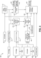
- FIG. 4 is a diagram illustrating a method for power regulation of the systems 200 and 300.
- the method 400 receives five inputs when regulating the voltage produced by systems such as the systems 200 and 300.
- the method 400 receives a DC current 401, a DC voltage 403, an AC voltage 405, an AC current 407, and a DC field current 409.
- the DC current 401 and the DC voltage 403 are the current and voltage produced by the generator system provided by the system to potentially connected loads.
- the AC voltage 405 and the AC current 407 are the voltage and current provided by the generator in the generator system before conversion from AC to DC.
- the DC field current 409 may refer to a DC field current applied to the exciter stator to drive the operation of an exciter.
- the method 400 receives the various inputs and determines how to regulate the voltage between a DC POR and an AC POR. For example, using the DC current 401, the method 400 proceeds at 411, where a load-off transient is detected. Also, using the DC voltage 403, the method 400 proceeds at 413, where DC voltage is fed back to facilitate the DC voltage regulation at the DC POR. For example, the DC voltage regulation may be provided to the GCU, which then regulates the DC voltage. The DC voltage and the outcome of the detection of the load-off transient may be provided to an AC POR or DC POR selection logic at 419.
- the method 400 receives the AC voltage at 415, where the AC voltage is feed back for regulation.
- the AC voltage 405 when the AC voltage 405 is produced by a six-phase generator, the AC voltage 405 includes six voltage measurements. Accordingly, the method 400 may also calculate a composite value for the six voltage measurements.
- the method 400 calculates a root-mean-square (RMS) value for the AC voltages 405.
- the RMS value 417 may also be provided to the AC voltage feedback 415, where the AC voltage feedback 415 uses the RMS value 417 for regulation of the AC voltage produced by the generator.
- the AC voltage feedback 415 may be additionally provided to the AC POR or DC POR selection logic 419.
- the selection logic 419 uses the DC voltage, the detected load-off transient, and the AC voltage feedback to determine whether to regulate the DC voltage or the AC voltage. For example, the selection logic may monitor the AC voltages and the DC bus voltages. When the load-off transient is detected, the selection logic 419 determines that the POR should switch from the DC voltage regulator to the AC voltage regulator. For example, the selection logic 419 determines that there is no load or a light load during a voltage buildup condition and/or steady-state operation and that the GCU should change the POR from the DC voltage regulator to AC voltage regulator. By switching the POR from the DC voltage regulator to the AC voltage regulator, a generator terminal voltage may remain stable without oscillations and maintain a desired AC line-to-line peak voltage during no-load or light-load conditions while improving voltage transients during load-on conditions.
- the method 400 proceeds at 421 with controlling an FDR and a DBR.
- the FDR and DBR may be controlled partly by DBR hardware and partly by a GCU.
- the FDR and DBR control may receive the output from the load-off transient detection and the feedback DC voltage. From the inputs, the FDR and DBR control may detect an overvoltage and turn on the DBR during a load-off transient.
- DBR hardware may include an overvoltage detection circuit during the load-off transient.
- the DBR control is taken over by the GCU.
- the GCU can produce FDR commands 423 and DBR commands 425 to control the operation of both the FDR and the DBR.
- the method 400 proceeds at 427, where a power limit, current limit, and average RMS measurements are calculated for the AC power measurements. For example, power limit, current limit, and average RMS measurements are calculated based on the AC current measurements, an RMS value for the AC current, and an RMS value for the AC voltage.
- the method 400 then proceeds at 431, where a logic selects a regulation loop. For example, using the calculated limits, the average RMS value, and the AC POR or DC POR selection, the system selects the feedback loop in either the AC POR or the DC POR to be regulated.
- the method 400 proceeds at 435, where multiple inputs are provided for use by voltage and current proportional-integral (PI) controllers.
- the voltage and current PI controllers may receive signals from the regulation loop selection logic, the FDR and DBR control, an average RMS current, and a measurement of the DC field current 409 from the exciter. Using the various inputs, the voltage and current PI controllers may provide a signal having a specific duty cycle 437 that drives the rotation of the generator. The voltage and current PI controllers can then control the voltage and current produced by the generator.
- PI proportional-integral
- FIG. 5 is a flowchart diagram of a method 500 for activating either DC voltage regulation or AC voltage regulation for power produced by a generator.
- Method 500 proceeds at 501, where operating conditions of a power generator having an AC generator and a DC converter are monitored.
- the method 500 proceeds at 503, it is determined whether the power generator is regularly operating. As described above, the power generator is regularly operating when providing DC power to a load as compared to light-load or no-load operation (or transitions between operative states).
- the method 500 proceeds at 505, where DC voltage regulation is activated.
- the method 500 proceeds at 507, where AC voltage regulation is activated. Additionally, after activating either the DC voltage regulation or the AC voltage regulation, the method 500 returns to 501 to continue monitoring operating conditions.
Landscapes
- Engineering & Computer Science (AREA)
- Power Engineering (AREA)
- Control Of Eletrric Generators (AREA)
Description
- For various reasons, aerial and ground vehicles increasingly use electricity to control operations and provide various services. For example, different electrical systems are being added to the vehicles to provide additional features. Also, previously non-electrical systems are being electrified, like using hybrid-electric propulsion systems instead of traditional propulsion systems. Vehicles may include power generators to provide at least a portion of the power used by the various systems.
- Further, as aerial and ground vehicles evolve, particularly over the past few decades, so has the demand for electrical systems that enable the functionality of the vehicles. Particularly for aerial and ground vehicles, electrification has resulted in a demand for systems that can produce high voltage direct current (HVDC) at high power levels (i.e., 100 kW or greater). Documents cited during prosecution include
US 2009/174188 A1 ;EP 3 772 816 A1 ;US 2011/133703 A1; "Excitation System Technologies for Wound-Field Synchronous Machines: Survey of Solutions and Evolving Trends" by Kristiansen et al. ; andUS 2012/106007 A1 . -
US 2009/174188 A1 discloses a three-core synchronous design, wherein a rectifier in the form of a main IGBT/ diode bridge is connected after the generator. In this case, the POR is always the DC voltage after the rectifier, but an AC voltage loop present in the control scheme is mentioned as playing an important role during load transients for keeping the DC voltage of the POR in a desired range. -
EP 3 772 816 A1 considers the possibility of using either the AC voltage at the output of the generator (input of the rectifier) as POR, or the DC voltage at the output of the rectifier as POR, but in different embodiments. -
US 2011/106007 A1 discloses a POR selector to switch the regulation input, but does it among the DC voltage output of two rectifiers, each of them after the generator, and the switching is based on a failure. - Aspects and preferred embodiments of the invention are defined in the appended claims. Systems and methods for voltage regulation of high voltage direct current systems are provided. Disclosed herein is a system includes a generator that generates alternating current (AC) voltage. The system further includes a power converter that converts the AC voltage into regulated direct current (DC) voltage. Also, the system includes a voltage regulator. Thevoltage regulator includes an AC voltage regulator that regulates the AC voltage generated by the generator. Also, the voltage regulator includes a DC voltage regulator that regulates the DC voltage produced by the power converter. Moreover, the voltage regulator includes a regulator selector that selectively activates one of the AC voltage regulator and the DC voltage regulator based on a current from the power converter and at least one of a voltage of the generator and a voltage of the power converter.
- Drawings accompany this description and depict only examples which should not be considered limiting in scope.
-
FIG. 1 is a block diagram illustrating a typical system providing alternating current voltage regulation described herein; -
FIG. 2 is a block diagram illustrating a system for voltage regulation of a high voltage direct current (DC) system according to the present disclosure: -
FIG. 3 is a schematic diagram illustrating a system for voltage regulation of a high voltage DC system according to the present disclosure: -
FIG. 4 is a diagram of an algorithm for providing voltage regulation for high voltage DC systems according to the present disclosure; and -
FIG. 5 is a flowchart diagram of a method for providing voltage regulation for high voltage DC systems according to the present disclosure. - Under common practice, the various described features are not drawn to scale but are drawn to emphasize specific features relevant to the examples.
- In the following detailed description, reference is made to the accompanying drawings that form a part of the present description and in which is shown, through illustration, specific examples. However, since the scope of the present invention is defined by the appended claims, it is to be understood that these and other examples may be used and that logical, mechanical, and electrical changes may be made, wherein the examples and their changes are covered by the present invention only if they do not contradict the appended claims (i.e. if they comprise at least all features of at least one of the independent claims).
- The present disclosure provides systems and methods for voltage regulation of high voltage direct current (HVDC) systems. Power systems may produce direct current (DC) electrical power by converting alternating current (AC) electrical power generated by an AC generator. The present system includes a DC voltage regulator for regulating the voltage of the DC electrical power and an AC voltage regulator for regulating the voltage of the AC electrical power. A regulator selector determines whether to use the DC voltage regulator or the AC voltage regulator by monitoring the voltage of the AC electrical power and the HVDC electrical power. As used herein, the term "high voltage direct current" or "HVDC" means a direct current (DC) potential difference of 270 VDC or greater. Typically, the regulator selector identifies the DC voltage as the point of regulation (POR), namely DC voltage regulator, and selects the AC voltage as the POR, namely AC voltage regulator, based on monitoring HVDC bus voltages and HVDC bus currents. Switching to the AC voltage regulator from the DC voltage regulator based on monitoring HVDC bus voltages and currents stabilizes the generator terminal voltage without oscillations, improves AC line to line peak voltage during the no-load/light load conditions, and improves voltage transients during load-on.
-
FIG. 1 is a block diagram illustrating a typical implementation of agenerator system 101. As shown, thegenerator system 101 may be a brushless AC motor/generator. Thegenerator system 101 may include a permanent magnet generator (PMG) 105, anexciter 107, amain generator 111, a generator control unit (GCU) 127, and one ormore rectifier assemblies 109. A generator system, such as that shown asgenerator system 101, may operate as a startergenerator for a gas turbine engine in aircraft, space, marine, land, or other vehicle-related applications that use gas turbine engines. Also, thegenerator system 101 may provide electrical power for various other systems found on vehicles or other stationary devices. Some aircraft applications use gas turbine engines for propulsion (e.g., the aircraft's main engines) and/or for power (e.g., the auxiliary power unit (APU)). - When the
generator system 101 operates, ashaft 103 rotates the rotor of thePMG 105, theexciter rotor 107, and themain generator rotor 111. In the depicted example, theshaft 103 rotates thePMG 105, theexciter rotor 107, and themain generator rotor 111 along a single axis at the same rotational speed. However, in other embodiments, the PMG 105 may rotate along a different axis with a different rotor. Moreover, the relative positioning of thePMG 105, theexciter 107, and themain generator 111 can be modified in relation to one another. - As illustrated, as the
shaft 103 rotates, thePMG 105 generates and supplies PMGAC power 113 to the GCU 127. The GCU 127 may include arectifier 125 that receives the PMGAC power 113 from thePMG 105 and converts the PMGAC power 113 to DC power. When aPMG 105 is not included in thegenerator system 101, a separateDC power input 155 can function as a DC power source. The GCU 127 may include aDC controller 123 that is controlled by acontroller 121. The GCU 127 may direct theDC controller 123 to providecontrollable DC power 115 to a stator of theexciter 107. As theshaft 103 rotates theexciter 107, theexciter 107 may supply AC power to therectifier assemblies 109. The output from therectifier assemblies 109 is DC power supplied to power themain generator 111, where themain generator 111 outputs AC power. - During operation, the
generator system 101 may output three-phase AC power from themain generator 111. One or more generator output leads 117 may supply the generated AC power to one ormore loads 119. As used herein, a load in the one ormore loads 119 refers to a system or device that uses electrical power at various frequencies and/or voltages produced by thegenerator system 101. TheGCU 127 can regulate the power output based upon monitoring the voltage and current generated by themain generator 111 through the generator output leads 117 and comparing the voltage and current against areference voltage 129. TheGCU 127 may regulate the AC voltage produced by themain generator 111 at a constant value when subjected to one ormore loads 119 or speed variations. When regulating the AC voltage, theGCU 127 may measure the voltages and currents at the AC POR 131 (at the output of the main generator 111) as feedback, and theGCU 127 may use the measurements to control excitation voltages for themain generator 111. - In embodiments of the present disclosure, a power converter converts the AC voltage, generated by systems such as the
generator system 101 shown inFIG. 1 , to a DC voltage. Systems having a typical GCU (like GCU 127) may not regulate the voltage correctly. For example, some typical systems may generate HVDC with a three-phase AC generator (such as the generator system 101) with diode rectifiers. Other typical systems may generate HVDC with a multi-phase AC generator and diode rectifiers. These generator topologies may be subject to certain problems with DC POR. One problem may include generator voltage instability during voltage buildup with DC POR under no-load conditions. Another problem with DC POR may include voltage overshoot during full load to no load transients, full load to light load transients, or both. - When a system experiences generator voltage instability with DC POR during voltage buildup under no-load conditions, a generator terminal voltage becomes unstable if the DC POR voltage is higher than a DC POR reference voltage. As the system is under a no-load condition, DC bus capacitors may remain charged and keep the voltage at a high value, and the generator terminal voltage may reduce continuously because of action by a generator control unit. During this period, the diodes of a rectifier may be in reverse bias and cause voltage instability.
- As stated above, a system may experience DC POR voltage overshoots during full-load to no-load or full-load to light-load transients. The transients caused by the removal or lightening of the load can lead to several issues. For example, when a load is suddenly removed, the DC POR voltage may instantly increase, leading to a DC bus overvoltage because of the load transient. In some examples, when a load is removed, the time to discharge the DC bus voltage to a normal voltage is extended because of DC bus capacitance. Extending the time to discharge can lead to the voltage exceeding voltage transient requirements defined in standards like the MIL-Std-704F or other stated design requirements. Additionally, if the DC bus capacitances are set to small values to meet voltage transient requirements, the DC bus overvoltage amplitude may exceed the overvoltage limit, and a system may experience DC overvoltage faults. Further, the terminal voltage of the generator may decrease because of the actions of a generator control unit, causing a system to be in an unstable state.
- Embodiments of the present disclosure address generator voltage instability with a DC POR by monitoring AC power voltages and HVDC bus voltages and currents. For example, systems switch the POR from DC voltage regulation to AC voltage regulation based on the monitoring of the AC power voltages and the HVDC bus voltages. Systems may switch the POR from DC to AC voltage regulation upon detecting either no-load or a light-load during voltage buildup conditions or steady-state operation. Further, during load transients from full-load to no-load or light-load, the GCU may switch the POR to AC voltage regulation based on the monitoring of the HVDC bus voltages and currents. When the GCU switches the POR to AC voltage regulation, a GCU may regulate the generator voltage based on a defined reference voltage that monitors the AC voltages generated by the generator. Swapping the POR from the DC voltage regulation to AC voltage regulation stabilizes the generator terminal voltage without oscillations and improves the performance of the AC line-to-line peak voltage during no-load or light-load conditions and improves the voltage transient during load-on.
- In certain embodiments, in addition to swapping the POR from DC voltage to the AC voltages, a generator system may address the transient response during load-off by detecting a load-off transient. When the system detects a load-off transient, the generator system may control a field dump resistor (FDR) and a dynamic break resistor (DBR). The GCU may include the FDR to increase the rate that field energy is dissipated when activated. Additionally, the DBR limits the DC bus overvoltage to bring it back to normal steady-state limits.
- The generator system may control the DBR using DBR hardware in conjunction with the GCU. The DBR hardware and/or the GCU may detect an overvoltage and turn on the DBR during a load-off transient. For example, the DBR hardware initially controls the DBR using an overvoltage detection circuit during a load-off transient to limit a DC bus overvoltage. After the initial operation of the DBR hardware control, the GCU may control the operation of the DBR. The initial control of the DBR by the DBR hardware control may reduce the delay on the DBR operation when a load-off transient is detected.
- In some embodiments, a DBR power rating may depend on the highest voltage limited by the DBR and on a DC bus capacitor. For example, to meet specific operational requirements (such as the MIL-Std-704f voltage transient requirement), the DC bus voltage should be below the DC voltage limit and should come back to steady-state limits within a specific time period from the instant a load-off transient begins. Once the DC bus voltage returns to steady-state, the DBR hardware or GCU may turn off the DBR. The size of the DBR may be proportional to the duration of the time used to come back from the load-off transient to steady-state. For example, a faster return to steady-state may permit a smaller DBR size. The reduction of DBR size may provide some advantages in certain applications. Effective control of the DBR allows for reducing a DC bus capacitor rating, permitting a reduction in capacitor size.
- In some embodiments, either the DBR hardware or the GCU coordinates the operation of the DBR with the FDR to improve the control of the DC bus voltage. For example, during the operation of the DBR, the FDR may be active, and the pulse width modulation (PWM) of the exciter may be disabled to permit improved control of the DC bus voltage. After the operation of the DBR completes, the FDR can be disabled, and the PWM of the exciter may enter an active state.
- Therefore, embodiments described herein are drawn toward systems and methods that enable the regulation of HVDC produced by generators. In particular, systems and methods described herein may help the regulation of the HVDC to achieve defined industry standards.
-
FIG. 2 is a block diagram of asystem 200 that switches the POR between a DC voltage regulator and an AC voltage regulator based on the monitoring of HVDC bus voltages and HVDC bus currents. Thesystem 200 includes agenerator 201 and apower converter 203 for converting AC power produced by thegenerator 201 into DC power. Thepower converter 203 may be a rectifier, a series of rectifiers, or other suitable device for converting AC power into DC power. Thegenerator 201 may function similar to thegenerator system 101 described above inFIG. 1 . For example, thegenerator 201 may be a multi-phase generator that produces AC power. In some embodiments, thegenerator 201 produces three-phase, six-phase, or other number of multi-phase AC power. Further, thegenerator 201 may include a PMG (such asPMG 105 inFIG. 1 ) that generates AC power, which is then converted to DC power for the operation of an exciter (such asexciter 107 inFIG. 1 ). Alternatively, thegenerator 201 may receive DC power through aDC power input 255. - In certain embodiments, the
system 200 may provide DC power to other systems (load 213) coupled to thegenerator 201. To provide the DC power, thegenerator 201 provides the generated AC power to apower converter 203, thepower converter 203 converts the AC power into DC power, and provides the DC power through a DC bus 212 for use by aload 213. Theload 213 may function similar to the one ormore loads 119 described above inFIG. 1 . The DC bus 212 may have aDC bus capacitor 215 that acts as a capacitance bank for the distribution of DC power to theload 213. - In exemplary embodiments, the
system 200 includes avoltage regulator 205 that functions similar to theGCU 127 inFIG. 1 . In contrast to theGCU 127, thevoltage regulator 205 includes aregulator selector 223 that selects one of a DC voltage regulator and an AC voltage regulator based on DC and AC power measurements. Theregulator selector 223 may implement logic that determines whether to switch to AC voltage regulation or DC voltage regulation based on the DC and AC power measurements. Theregulator selector 223 may be implemented using hardware, software, or a combination of hardware and software. As theregulator selector 223 can be implemented with software, thevoltage regulator 205 may include a processor that executes some instructions when selecting one of the AC or DC voltage regulation. - In some examples, the
voltage regulator 205 may manage separate DC and AC voltage regulators that are part of thevoltage regulator 205. Alternatively, thevoltage regulator 205 may receive input signals for both the DC and AC voltage and be a single device that selectively regulates generator 201 (AC voltage) and power converter 203 (DC voltage). In some exemplary implementations, thevoltage regulator 205 may receiveDC measurements 211 from the DC bus 212 andAC measurements 209 from thegenerator 201. The controlled excitation to thegenerator 201 may be represented bycontrol signal 207. TheDC measurements 211 may include the DC voltage and the DC current. Similarly, the AC measurements may include the AC voltage and the AC current. During regular operation, theregulator selector 223 may select the DC voltage regulator to functions as the point of regulation for thesystem 200. As used herein, regular operation refers to the operation of thesystem 200, when thegenerator 201 is providing power to aload 213. Theregulator selector 223 may monitor the DC and AC measurements to detect no-load, light-load, and transient conditions, e.g., not "regular operation." When theregulator selector 223 detects the no-load/light-load during voltage buildup or steady-state operation, theregulator selector 223 may switch the POR from the DC voltage regulation to the AC voltage regulation. Additionally, thevoltage regulator 205 may switch the POR to AC voltage regulation during load transients. - In additional embodiments, the
system 200 may include a dynamic break resistor (DBR)unit 217. TheDBR unit 217 may include aDBR 216 and an insulated gate bipolar transistor (IGBT) 218. TheDBR 216 may be turned on by theIGBT 218 that is controlled by hardware or the voltage regulator under load off conditions. For example, thevoltage regulator 205 may control theDBR unit 217 by sending DBR control signals 219 to theDBR unit 217. Additionally, theDBR hardware 218 may provide partial control of theDBR 216, where the DBR hardware control functions together with thevoltage regulator 205 to control the operation of theDBR 216. As described above, theDBR unit 217 limits the DC bus overvoltage and brings the DC bus voltage back to steady-state. Additionally, as described above, thevoltage regulator 205 may include anFDR 221, which increases the dissipation rate of field energy during load-off transients. Accordingly, thesystem 200 can overcome the generator voltage instability with the DC POR during voltage buildup under no-load conditions. Also, thesystem 200 can regulate DC voltage overshoot during full-load to either no-load or light-load transients. - In some embodiments, the function of the voltage regulator 205 (for example the regulator selector 223) may be performed by hardware or through the execution of instructions performed by a processor that receives the various measurements from the
system 200. When thevoltage regulator 205 includes a processor, the processor may execute portions of the methods described in the present disclosure. For example, the processor and/or other computational devices used within thesystem 200 may be implemented using software, firmware, hardware, or an appropriate combination thereof. The processor and other computational devices may be supplemented by, or incorporated in, specially designed application-specific integrated circuits (ASICs) or field programmable gate arrays (FPGAs). The processors and other computational devices can also include or function with software programs, firmware, or other computer-readable instructions for carrying out various process tasks, calculations, and control functions used in the methods and systems described herein. - The methods described herein may be implemented or controlled by computerexecutable instructions, such as program modules or components, executed by at least the processors or other computing devices. Generally, program modules include routines, programs, objects, data components, data structures, algorithms, and the like, which perform particular tasks or implement particular abstract data types.
- Instructions for carrying out the various process tasks, calculations, and generation of other data used in the operation of the methods described herein may be implemented in software, firmware, or other computer-readable instructions. These instructions are typically stored on appropriate computer program products that include computer-readable media used to store computer-readable instructions or data structures. The computer-readable media may store computer-readable instructions or data structures. Such a computer-readable medium may be available media that can be accessed by a general-purpose or special-purpose computer or processor, or any programmable logic device.
- Suitable computer-readable storage media may include, for example, non-volatile memory devices including semi-conductor memory devices such as Random Access Memory (RAM), Read Only Memory (ROM), Electrically Erasable Programmable ROM (EEPROM), or flash memory devices; magnetic disks such as internal hard disks or removable disks; optical storage devices such as compact discs (CDs), digital versatile discs (DVDs), Blu-ray discs; or any other media that can carry or store desired program code as computerexecutable instructions or data structures.
-
FIG. 3 is a schematic diagram of asystem 300 that switches the POR between DC voltage regulation and AC voltage regulation based on the monitoring of HVDC bus voltages and HVDC bus currents. Thesystem 300 includes agenerator system 301. Thegenerator system 301 is similar to thegenerator system 101 regarding the generation of AC electrical power. However, thegenerator system 301 may generate six-phase or other number of multi-phase AC electrical power in contrast to the three-phase electrical power generated by thegenerator system 101 inFIG. 1 . - To generate the AC electrical power, the
generator system 301 includes arotor 303 that rotates anexciter 307 in relation to anexciter stator 308. Theexciter 307 may function similarly to theexciter 107 inFIG. 1 . For example, theexciter 307 may generate three-phase AC electrical power provided to arectifier assembly 309. Therectifier assembly 309 may function similarly to therectifier assemblies 109. Therectifier assembly 309 provides DC electrical power for driving agenerator rotor 310 that rotates in relation to agenerator stator 311. Thegenerator stator 311 may provide AC power as an output of thegenerator system 301. - In certain embodiments, the
generator system 301 provides measurements of theAC generator voltage 331 and an AC generator current 333 to aGCU 325, which functions as an AC voltage regulator. Accordingly, the output of thegenerator system 301 may function as an input to the AC voltage regulator. TheGCU 325 may also provide an excitation field to theexciter stator 308 to control the operation of theexciter 307. Alternatively, DC power can be received through aDC power input 355 to provide the excitation field to theexciter stator 308. In addition to providing the measurements of theAC generator voltage 331 and the AC generator current 333 to theGCU 325, thegenerator system 301 may also provide AC electrical power to apower converter 313, where thepower converter 313 converts the AC voltage to DC voltage. - In exemplary embodiments, after the
system 300 converts the AC voltage to DC voltage, thesystem 300 may provide the DC voltage to a load through aDC bus 349. TheDC bus 349 may include a DC bus capacitor orcapacitors 335 and 337 that function similar to theDC bus capacitor 215. Additionally, theDC bus 349 may provide measurements of the DC power to theGCU 325. For example, theDC bus 349 may provide aDC voltage measurement 341 and a DCcurrent measurement 343 to theGCU 325. TheGCU 325 may then provide DCpower distribution control 345 to theDC bus 349 by controlling an output DC contactor (ODCC) 347. In some implementations, theGCU 325 may include the functionality of the regulator selector (such as theregulator selector 223 inFIG. 2 ) by selecting either theDC voltage regulation 353 or theAC voltage regulation 351. Additionally, theGCU 325 may also include the functionality for providing theDC voltage regulation 353 andAC voltage regulation 351. Alternatively, the GCU may coordinate the operation of separate devices that provide theDC voltage regulation 353 and theAC voltage regulation 351.DC voltage regulation 353 and theAC voltage regulation 351 can be implemented in the same physical unit. - As described above, the
GCU 325 may operate in conjunction with a DBR and FDR to provided DC voltage regulation.FIG. 4 is a diagram illustrating a method for power regulation of thesystems method 400 receives five inputs when regulating the voltage produced by systems such as thesystems method 400 receives a DC current 401, aDC voltage 403, anAC voltage 405, an AC current 407, and a DC field current 409. The DC current 401 and theDC voltage 403 are the current and voltage produced by the generator system provided by the system to potentially connected loads. TheAC voltage 405 and the AC current 407 are the voltage and current provided by the generator in the generator system before conversion from AC to DC. The DC field current 409 may refer to a DC field current applied to the exciter stator to drive the operation of an exciter. - As shown, the
method 400 receives the various inputs and determines how to regulate the voltage between a DC POR and an AC POR. For example, using the DC current 401, themethod 400 proceeds at 411, where a load-off transient is detected. Also, using theDC voltage 403, themethod 400 proceeds at 413, where DC voltage is fed back to facilitate the DC voltage regulation at the DC POR. For example, the DC voltage regulation may be provided to the GCU, which then regulates the DC voltage. The DC voltage and the outcome of the detection of the load-off transient may be provided to an AC POR or DC POR selection logic at 419. - In exemplary embodiments, the
method 400 receives the AC voltage at 415, where the AC voltage is feed back for regulation. For example, when theAC voltage 405 is produced by a six-phase generator, theAC voltage 405 includes six voltage measurements. Accordingly, themethod 400 may also calculate a composite value for the six voltage measurements. For example, at 417, themethod 400 calculates a root-mean-square (RMS) value for the AC voltages 405. TheRMS value 417 may also be provided to theAC voltage feedback 415, where theAC voltage feedback 415 uses theRMS value 417 for regulation of the AC voltage produced by the generator. TheAC voltage feedback 415 may be additionally provided to the AC POR or DCPOR selection logic 419. - In certain embodiments, the
selection logic 419 uses the DC voltage, the detected load-off transient, and the AC voltage feedback to determine whether to regulate the DC voltage or the AC voltage. For example, the selection logic may monitor the AC voltages and the DC bus voltages. When the load-off transient is detected, theselection logic 419 determines that the POR should switch from the DC voltage regulator to the AC voltage regulator. For example, theselection logic 419 determines that there is no load or a light load during a voltage buildup condition and/or steady-state operation and that the GCU should change the POR from the DC voltage regulator to AC voltage regulator. By switching the POR from the DC voltage regulator to the AC voltage regulator, a generator terminal voltage may remain stable without oscillations and maintain a desired AC line-to-line peak voltage during no-load or light-load conditions while improving voltage transients during load-on conditions. - To deal with overshoot, the
method 400 proceeds at 421 with controlling an FDR and a DBR. As discussed above, the FDR and DBR may be controlled partly by DBR hardware and partly by a GCU. For example, the FDR and DBR control may receive the output from the load-off transient detection and the feedback DC voltage. From the inputs, the FDR and DBR control may detect an overvoltage and turn on the DBR during a load-off transient. As described above, DBR hardware may include an overvoltage detection circuit during the load-off transient. After the initial operation of the DBR hardware control, the DBR control is taken over by the GCU. For example, after the initial operation of the DBR hardware control, the GCU can produce FDR commands 423 and DBR commands 425 to control the operation of both the FDR and the DBR. - In certain embodiments, the
method 400 proceeds at 427, where a power limit, current limit, and average RMS measurements are calculated for the AC power measurements. For example, power limit, current limit, and average RMS measurements are calculated based on the AC current measurements, an RMS value for the AC current, and an RMS value for the AC voltage. Themethod 400 then proceeds at 431, where a logic selects a regulation loop. For example, using the calculated limits, the average RMS value, and the AC POR or DC POR selection, the system selects the feedback loop in either the AC POR or the DC POR to be regulated. - In exemplary embodiments, the
method 400 proceeds at 435, where multiple inputs are provided for use by voltage and current proportional-integral (PI) controllers. For example, the voltage and current PI controllers may receive signals from the regulation loop selection logic, the FDR and DBR control, an average RMS current, and a measurement of the DC field current 409 from the exciter. Using the various inputs, the voltage and current PI controllers may provide a signal having aspecific duty cycle 437 that drives the rotation of the generator. The voltage and current PI controllers can then control the voltage and current produced by the generator. -
FIG. 5 is a flowchart diagram of amethod 500 for activating either DC voltage regulation or AC voltage regulation for power produced by a generator.Method 500 proceeds at 501, where operating conditions of a power generator having an AC generator and a DC converter are monitored. Themethod 500 proceeds at 503, it is determined whether the power generator is regularly operating. As described above, the power generator is regularly operating when providing DC power to a load as compared to light-load or no-load operation (or transitions between operative states). When it is determined that the power generator is regularly operating, themethod 500 proceeds at 505, where DC voltage regulation is activated. Alternatively, when it is determined that the power generator is not regularly operating, themethod 500 proceeds at 507, where AC voltage regulation is activated. Additionally, after activating either the DC voltage regulation or the AC voltage regulation, themethod 500 returns to 501 to continue monitoring operating conditions.
Claims (9)
- A system (200) comprising;a generator (201) configured to generate alternating current, AC, voltage;a power converter (203) configured to convert the AC voltage into regulated direct current, DC, voltage; anda voltage regulator (205) configured to function as a generator control unit for the generator (201), the voltage regulator (205) comprising:an AC voltage regulator (351) configured to regulate the AC voltage based on an AC output of the generator (201);a DC voltage regulator (353) configured to regulate the DC voltage based on a DC output of the power converter (203); anda regulator selector (223) configured to select the DC voltage regulator during regular operation in which the DC voltage is provided to a load (213), and to select the AC voltage regulator (351) when at least one of a current from the power converter (203) and a voltage of the power converter (203) indicate at least one of a no-load condition, a light-load condition, and a transient.
- The system (200) of claim 1, wherein the regulator selector (223) is configured to select the AC voltage regulator (351) based on a detected no-load condition, wherein the regulator selector (223) is configured to detect the no-load condition based on monitoring the current from the power converter (203), wherein the voltage regulator (205) is configured to regulate the generator AC voltages to a defined reference voltage during a transition from a load-on condition to at least one of the no-load condition and a light load condition.
- The system (200) of claim 1, wherein the voltage regulator (205) includes a field dump resistor (FDR) (221) and is configured to provide control of a dynamic break resistor (DBR) (216), wherein operation of the DBR (216) is additionally controlled by DBR hardware (218) and the DBR hardware (218) initially controls the operation of the DBR (217) upon detection of a load-off transient, wherein the control of the DBR (217) passes from the DBR hardware (218) to the voltage regulator (205).
- The system (200) of claim 1, further comprising a high voltage DC bus (212), wherein the high voltage DC bus (212) is configured to provide the DC voltage for use by one or more loads (213).
- The system (200) of claim 1, wherein the voltage regulator (205) is a generator control unit (325).
- A method comprising:monitoring operating conditions of a system (200) having a generator (201) that generates AC voltage and a power converter (203) that converts the AC voltage into regulated DC voltage;determining whether the power generator (200) is regularly operating based on a current of the DC bus (212) and the DC voltage, wherein the power generator (200) is regularly operating when providing DC voltage to a load (213);when determining that the power generator (200) is regularly operating, selecting DC voltage regulation to regulate the DC voltage based on a DC output of the power converter (203);when determining that the power generator (200) is not regularly operating by identifying, based on at least one of a current from the power converter (203) and a voltage of the power converter (203), at least one of a no-load condition, a light-load condition, and a transient, selecting AC voltage regulation to regulate the AC voltage based on an AC output of the generator (201); andcontrolling operation of the generator based on the selected voltage regulation.
- The method of claim 6, wherein identifying the no-load condition is based on monitoring the current of the DC bus (212), wherein the AC voltage regulation regulates the value of the AC voltage to a defined reference voltage during a transition from a load-on condition to the no-load condition.
- The method of claim 6, further comprising controlling operation of a field dump resistor (FDR) (221) and a dynamic break resistor (DBR) (216).
- The method of claim 6, wherein a generator control unit (325) determines whether the power generator (200) is regularly operating.
Applications Claiming Priority (2)
| Application Number | Priority Date | Filing Date | Title |
|---|---|---|---|
| IN202111048163 | 2021-10-22 | ||
| US17/586,512 US11770084B2 (en) | 2021-10-22 | 2022-01-27 | Voltage regulation of high voltage direct current systems |
Publications (2)
| Publication Number | Publication Date |
|---|---|
| EP4170894A1 EP4170894A1 (en) | 2023-04-26 |
| EP4170894B1 true EP4170894B1 (en) | 2024-06-12 |
Family
ID=83902948
Family Applications (1)
| Application Number | Title | Priority Date | Filing Date |
|---|---|---|---|
| EP22202992.8A Active EP4170894B1 (en) | 2021-10-22 | 2022-10-21 | Voltage regulation of high voltage direct current systems |
Country Status (1)
| Country | Link |
|---|---|
| EP (1) | EP4170894B1 (en) |
Family Cites Families (4)
| Publication number | Priority date | Publication date | Assignee | Title |
|---|---|---|---|---|
| US7508086B2 (en) * | 2006-03-24 | 2009-03-24 | General Electric Company | Aircraft engine starter/generator and controller |
| US8358111B2 (en) * | 2009-12-03 | 2013-01-22 | Hamilton Sundstrand Corporation | Architecture for dual source electric power generating system |
| US8699188B2 (en) * | 2010-10-27 | 2014-04-15 | Hamilton Sundstrand Corporation | Shunt regulator for overvoltage protection at transformer rectifier unit of electrical generating system |
| US11671038B2 (en) * | 2019-08-09 | 2023-06-06 | Hamilton Sundstrand Corporation | Control of a wound field synchronous generator for transient load response |
-
2022
- 2022-10-21 EP EP22202992.8A patent/EP4170894B1/en active Active
Also Published As
| Publication number | Publication date |
|---|---|
| EP4170894A1 (en) | 2023-04-26 |
Similar Documents
| Publication | Publication Date | Title |
|---|---|---|
| EP2137808B1 (en) | Dc voltage regulator | |
| US8008885B2 (en) | Power converters | |
| EP2068423B1 (en) | An AC power generation system | |
| US9673743B1 (en) | Efficient motor control | |
| CN108603916B (en) | Method for identifying faults in generator units | |
| JP3540152B2 (en) | Engine driven generator | |
| EP3644485B1 (en) | Control of an electrical power system responsive to sensing a ground fault | |
| US9270219B2 (en) | Voltage-controlled DC link for variable frequency generator excitation | |
| JP2004532595A (en) | How to operate a wind turbine | |
| KR20170015963A (en) | Method and device for optimizing efficiency of induction motor in electric vehicle | |
| US9660563B2 (en) | High voltage direct current system with improved generator excitation | |
| EP3518417A1 (en) | Real-time detection of motor faults with three-phase sine drive motors | |
| Rahnama et al. | Rotary diode failure detection in brushless exciter system of power plant synchronous generator | |
| US11770084B2 (en) | Voltage regulation of high voltage direct current systems | |
| CN106685289B (en) | Dynamic restriction device and dynamic restriction method for implementing such a device | |
| EP4170894A1 (en) | Voltage regulation of high voltage direct current systems | |
| US11894672B2 (en) | Wind turbine generator fault protection system | |
| US7990112B2 (en) | Adaptive field control of a variable frequency synchronous generator | |
| EP4131771A1 (en) | Drive device | |
| CN107517026B (en) | Synchronous rectification generator and protection method thereof | |
| JP2020088926A (en) | Power conversion device, and control method for power conversion device | |
| KR101372930B1 (en) | Pre-charging method of converter of wind power generating system | |
| TW201826685A (en) | Efficient motor control method and system thereof | |
| JP6441880B2 (en) | Inverter | |
| El Khil et al. | Sensorless field oriented control of doubly fed induction speed drive |
Legal Events
| Date | Code | Title | Description |
|---|---|---|---|
| PUAI | Public reference made under article 153(3) epc to a published international application that has entered the european phase |
Free format text: ORIGINAL CODE: 0009012 |
|
| STAA | Information on the status of an ep patent application or granted ep patent |
Free format text: STATUS: THE APPLICATION HAS BEEN PUBLISHED |
|
| AK | Designated contracting states |
Kind code of ref document: A1 Designated state(s): AL AT BE BG CH CY CZ DE DK EE ES FI FR GB GR HR HU IE IS IT LI LT LU LV MC ME MK MT NL NO PL PT RO RS SE SI SK SM TR |
|
| P01 | Opt-out of the competence of the unified patent court (upc) registered |
Effective date: 20230525 |
|
| STAA | Information on the status of an ep patent application or granted ep patent |
Free format text: STATUS: REQUEST FOR EXAMINATION WAS MADE |
|
| 17P | Request for examination filed |
Effective date: 20231024 |
|
| RBV | Designated contracting states (corrected) |
Designated state(s): AL AT BE BG CH CY CZ DE DK EE ES FI FR GB GR HR HU IE IS IT LI LT LU LV MC ME MK MT NL NO PL PT RO RS SE SI SK SM TR |
|
| GRAP | Despatch of communication of intention to grant a patent |
Free format text: ORIGINAL CODE: EPIDOSNIGR1 |
|
| STAA | Information on the status of an ep patent application or granted ep patent |
Free format text: STATUS: GRANT OF PATENT IS INTENDED |
|
| RIC1 | Information provided on ipc code assigned before grant |
Ipc: H02P 9/14 20060101ALI20231215BHEP Ipc: H02K 19/38 20060101ALI20231215BHEP Ipc: H02K 7/18 20060101ALI20231215BHEP Ipc: H02P 9/10 20060101AFI20231215BHEP |
|
| INTG | Intention to grant announced |
Effective date: 20240118 |
|
| GRAS | Grant fee paid |
Free format text: ORIGINAL CODE: EPIDOSNIGR3 |
|
| GRAA | (expected) grant |
Free format text: ORIGINAL CODE: 0009210 |
|
| STAA | Information on the status of an ep patent application or granted ep patent |
Free format text: STATUS: THE PATENT HAS BEEN GRANTED |
|
| AK | Designated contracting states |
Kind code of ref document: B1 Designated state(s): AL AT BE BG CH CY CZ DE DK EE ES FI FR GB GR HR HU IE IS IT LI LT LU LV MC ME MK MT NL NO PL PT RO RS SE SI SK SM TR |
|
| REG | Reference to a national code |
Ref country code: GB Ref legal event code: FG4D |
|
| REG | Reference to a national code |
Ref country code: CH Ref legal event code: EP |
|
| REG | Reference to a national code |
Ref country code: IE Ref legal event code: FG4D |
|
| REG | Reference to a national code |
Ref country code: DE Ref legal event code: R096 Ref document number: 602022003930 Country of ref document: DE |
|
| PG25 | Lapsed in a contracting state [announced via postgrant information from national office to epo] |
Ref country code: BG Free format text: LAPSE BECAUSE OF FAILURE TO SUBMIT A TRANSLATION OF THE DESCRIPTION OR TO PAY THE FEE WITHIN THE PRESCRIBED TIME-LIMIT Effective date: 20240612 |
|
| PG25 | Lapsed in a contracting state [announced via postgrant information from national office to epo] |
Ref country code: FI Free format text: LAPSE BECAUSE OF FAILURE TO SUBMIT A TRANSLATION OF THE DESCRIPTION OR TO PAY THE FEE WITHIN THE PRESCRIBED TIME-LIMIT Effective date: 20240612 Ref country code: HR Free format text: LAPSE BECAUSE OF FAILURE TO SUBMIT A TRANSLATION OF THE DESCRIPTION OR TO PAY THE FEE WITHIN THE PRESCRIBED TIME-LIMIT Effective date: 20240612 |
|
| REG | Reference to a national code |
Ref country code: LT Ref legal event code: MG9D |
|
| PG25 | Lapsed in a contracting state [announced via postgrant information from national office to epo] |
Ref country code: GR Free format text: LAPSE BECAUSE OF FAILURE TO SUBMIT A TRANSLATION OF THE DESCRIPTION OR TO PAY THE FEE WITHIN THE PRESCRIBED TIME-LIMIT Effective date: 20240913 |
|
| REG | Reference to a national code |
Ref country code: NL Ref legal event code: MP Effective date: 20240612 |
|
| PG25 | Lapsed in a contracting state [announced via postgrant information from national office to epo] |
Ref country code: ES Free format text: LAPSE BECAUSE OF FAILURE TO SUBMIT A TRANSLATION OF THE DESCRIPTION OR TO PAY THE FEE WITHIN THE PRESCRIBED TIME-LIMIT Effective date: 20240612 |
|
| PG25 | Lapsed in a contracting state [announced via postgrant information from national office to epo] |
Ref country code: LV Free format text: LAPSE BECAUSE OF FAILURE TO SUBMIT A TRANSLATION OF THE DESCRIPTION OR TO PAY THE FEE WITHIN THE PRESCRIBED TIME-LIMIT Effective date: 20240612 |
|
| PG25 | Lapsed in a contracting state [announced via postgrant information from national office to epo] |
Ref country code: NO Free format text: LAPSE BECAUSE OF FAILURE TO SUBMIT A TRANSLATION OF THE DESCRIPTION OR TO PAY THE FEE WITHIN THE PRESCRIBED TIME-LIMIT Effective date: 20240912 Ref country code: LV Free format text: LAPSE BECAUSE OF FAILURE TO SUBMIT A TRANSLATION OF THE DESCRIPTION OR TO PAY THE FEE WITHIN THE PRESCRIBED TIME-LIMIT Effective date: 20240612 Ref country code: HR Free format text: LAPSE BECAUSE OF FAILURE TO SUBMIT A TRANSLATION OF THE DESCRIPTION OR TO PAY THE FEE WITHIN THE PRESCRIBED TIME-LIMIT Effective date: 20240612 Ref country code: GR Free format text: LAPSE BECAUSE OF FAILURE TO SUBMIT A TRANSLATION OF THE DESCRIPTION OR TO PAY THE FEE WITHIN THE PRESCRIBED TIME-LIMIT Effective date: 20240913 Ref country code: FI Free format text: LAPSE BECAUSE OF FAILURE TO SUBMIT A TRANSLATION OF THE DESCRIPTION OR TO PAY THE FEE WITHIN THE PRESCRIBED TIME-LIMIT Effective date: 20240612 Ref country code: ES Free format text: LAPSE BECAUSE OF FAILURE TO SUBMIT A TRANSLATION OF THE DESCRIPTION OR TO PAY THE FEE WITHIN THE PRESCRIBED TIME-LIMIT Effective date: 20240612 Ref country code: BG Free format text: LAPSE BECAUSE OF FAILURE TO SUBMIT A TRANSLATION OF THE DESCRIPTION OR TO PAY THE FEE WITHIN THE PRESCRIBED TIME-LIMIT Effective date: 20240612 Ref country code: RS Free format text: LAPSE BECAUSE OF FAILURE TO SUBMIT A TRANSLATION OF THE DESCRIPTION OR TO PAY THE FEE WITHIN THE PRESCRIBED TIME-LIMIT Effective date: 20240912 |
|
| PG25 | Lapsed in a contracting state [announced via postgrant information from national office to epo] |
Ref country code: NL Free format text: LAPSE BECAUSE OF FAILURE TO SUBMIT A TRANSLATION OF THE DESCRIPTION OR TO PAY THE FEE WITHIN THE PRESCRIBED TIME-LIMIT Effective date: 20240612 |
|
| REG | Reference to a national code |
Ref country code: AT Ref legal event code: MK05 Ref document number: 1695066 Country of ref document: AT Kind code of ref document: T Effective date: 20240612 |
|
| PG25 | Lapsed in a contracting state [announced via postgrant information from national office to epo] |
Ref country code: NL Free format text: LAPSE BECAUSE OF FAILURE TO SUBMIT A TRANSLATION OF THE DESCRIPTION OR TO PAY THE FEE WITHIN THE PRESCRIBED TIME-LIMIT Effective date: 20240612 |
|
| PG25 | Lapsed in a contracting state [announced via postgrant information from national office to epo] |
Ref country code: PT Free format text: LAPSE BECAUSE OF FAILURE TO SUBMIT A TRANSLATION OF THE DESCRIPTION OR TO PAY THE FEE WITHIN THE PRESCRIBED TIME-LIMIT Effective date: 20241014 |
|
| PG25 | Lapsed in a contracting state [announced via postgrant information from national office to epo] |
Ref country code: PT Free format text: LAPSE BECAUSE OF FAILURE TO SUBMIT A TRANSLATION OF THE DESCRIPTION OR TO PAY THE FEE WITHIN THE PRESCRIBED TIME-LIMIT Effective date: 20241014 |
|
| PG25 | Lapsed in a contracting state [announced via postgrant information from national office to epo] |
Ref country code: PL Free format text: LAPSE BECAUSE OF FAILURE TO SUBMIT A TRANSLATION OF THE DESCRIPTION OR TO PAY THE FEE WITHIN THE PRESCRIBED TIME-LIMIT Effective date: 20240612 |
|
| PG25 | Lapsed in a contracting state [announced via postgrant information from national office to epo] |
Ref country code: EE Free format text: LAPSE BECAUSE OF FAILURE TO SUBMIT A TRANSLATION OF THE DESCRIPTION OR TO PAY THE FEE WITHIN THE PRESCRIBED TIME-LIMIT Effective date: 20240612 |
|
| PG25 | Lapsed in a contracting state [announced via postgrant information from national office to epo] |
Ref country code: IS Free format text: LAPSE BECAUSE OF FAILURE TO SUBMIT A TRANSLATION OF THE DESCRIPTION OR TO PAY THE FEE WITHIN THE PRESCRIBED TIME-LIMIT Effective date: 20241012 Ref country code: AT Free format text: LAPSE BECAUSE OF FAILURE TO SUBMIT A TRANSLATION OF THE DESCRIPTION OR TO PAY THE FEE WITHIN THE PRESCRIBED TIME-LIMIT Effective date: 20240612 |
|
| PG25 | Lapsed in a contracting state [announced via postgrant information from national office to epo] |
Ref country code: CZ Free format text: LAPSE BECAUSE OF FAILURE TO SUBMIT A TRANSLATION OF THE DESCRIPTION OR TO PAY THE FEE WITHIN THE PRESCRIBED TIME-LIMIT Effective date: 20240612 |
|
| PG25 | Lapsed in a contracting state [announced via postgrant information from national office to epo] |
Ref country code: SK Free format text: LAPSE BECAUSE OF FAILURE TO SUBMIT A TRANSLATION OF THE DESCRIPTION OR TO PAY THE FEE WITHIN THE PRESCRIBED TIME-LIMIT Effective date: 20240612 Ref country code: RO Free format text: LAPSE BECAUSE OF FAILURE TO SUBMIT A TRANSLATION OF THE DESCRIPTION OR TO PAY THE FEE WITHIN THE PRESCRIBED TIME-LIMIT Effective date: 20240612 |
|
| PG25 | Lapsed in a contracting state [announced via postgrant information from national office to epo] |
Ref country code: SM Free format text: LAPSE BECAUSE OF FAILURE TO SUBMIT A TRANSLATION OF THE DESCRIPTION OR TO PAY THE FEE WITHIN THE PRESCRIBED TIME-LIMIT Effective date: 20240612 |
|
| PG25 | Lapsed in a contracting state [announced via postgrant information from national office to epo] |
Ref country code: SM Free format text: LAPSE BECAUSE OF FAILURE TO SUBMIT A TRANSLATION OF THE DESCRIPTION OR TO PAY THE FEE WITHIN THE PRESCRIBED TIME-LIMIT Effective date: 20240612 Ref country code: SK Free format text: LAPSE BECAUSE OF FAILURE TO SUBMIT A TRANSLATION OF THE DESCRIPTION OR TO PAY THE FEE WITHIN THE PRESCRIBED TIME-LIMIT Effective date: 20240612 Ref country code: RO Free format text: LAPSE BECAUSE OF FAILURE TO SUBMIT A TRANSLATION OF THE DESCRIPTION OR TO PAY THE FEE WITHIN THE PRESCRIBED TIME-LIMIT Effective date: 20240612 Ref country code: PL Free format text: LAPSE BECAUSE OF FAILURE TO SUBMIT A TRANSLATION OF THE DESCRIPTION OR TO PAY THE FEE WITHIN THE PRESCRIBED TIME-LIMIT Effective date: 20240612 Ref country code: IS Free format text: LAPSE BECAUSE OF FAILURE TO SUBMIT A TRANSLATION OF THE DESCRIPTION OR TO PAY THE FEE WITHIN THE PRESCRIBED TIME-LIMIT Effective date: 20241012 Ref country code: EE Free format text: LAPSE BECAUSE OF FAILURE TO SUBMIT A TRANSLATION OF THE DESCRIPTION OR TO PAY THE FEE WITHIN THE PRESCRIBED TIME-LIMIT Effective date: 20240612 Ref country code: CZ Free format text: LAPSE BECAUSE OF FAILURE TO SUBMIT A TRANSLATION OF THE DESCRIPTION OR TO PAY THE FEE WITHIN THE PRESCRIBED TIME-LIMIT Effective date: 20240612 Ref country code: AT Free format text: LAPSE BECAUSE OF FAILURE TO SUBMIT A TRANSLATION OF THE DESCRIPTION OR TO PAY THE FEE WITHIN THE PRESCRIBED TIME-LIMIT Effective date: 20240612 |
|
| PG25 | Lapsed in a contracting state [announced via postgrant information from national office to epo] |
Ref country code: IT Free format text: LAPSE BECAUSE OF FAILURE TO SUBMIT A TRANSLATION OF THE DESCRIPTION OR TO PAY THE FEE WITHIN THE PRESCRIBED TIME-LIMIT Effective date: 20240612 |
|
| REG | Reference to a national code |
Ref country code: DE Ref legal event code: R097 Ref document number: 602022003930 Country of ref document: DE |
|
| PG25 | Lapsed in a contracting state [announced via postgrant information from national office to epo] |
Ref country code: DK Free format text: LAPSE BECAUSE OF FAILURE TO SUBMIT A TRANSLATION OF THE DESCRIPTION OR TO PAY THE FEE WITHIN THE PRESCRIBED TIME-LIMIT Effective date: 20240612 |
|
| PLBE | No opposition filed within time limit |
Free format text: ORIGINAL CODE: 0009261 |
|
| STAA | Information on the status of an ep patent application or granted ep patent |
Free format text: STATUS: NO OPPOSITION FILED WITHIN TIME LIMIT |
|
| REG | Reference to a national code |
Ref country code: DE Ref legal event code: R119 Ref document number: 602022003930 Country of ref document: DE |
|
| 26N | No opposition filed |
Effective date: 20250313 |
|
| PG25 | Lapsed in a contracting state [announced via postgrant information from national office to epo] |
Ref country code: MC Free format text: LAPSE BECAUSE OF FAILURE TO SUBMIT A TRANSLATION OF THE DESCRIPTION OR TO PAY THE FEE WITHIN THE PRESCRIBED TIME-LIMIT Effective date: 20240612 |
|
| PG25 | Lapsed in a contracting state [announced via postgrant information from national office to epo] |
Ref country code: DE Free format text: LAPSE BECAUSE OF NON-PAYMENT OF DUE FEES Effective date: 20250501 |
|
| PG25 | Lapsed in a contracting state [announced via postgrant information from national office to epo] |
Ref country code: LU Free format text: LAPSE BECAUSE OF NON-PAYMENT OF DUE FEES Effective date: 20241021 Ref country code: BE Free format text: LAPSE BECAUSE OF NON-PAYMENT OF DUE FEES Effective date: 20241031 |
|
| REG | Reference to a national code |
Ref country code: BE Ref legal event code: MM Effective date: 20241031 |
|
| PG25 | Lapsed in a contracting state [announced via postgrant information from national office to epo] |
Ref country code: SE Free format text: LAPSE BECAUSE OF FAILURE TO SUBMIT A TRANSLATION OF THE DESCRIPTION OR TO PAY THE FEE WITHIN THE PRESCRIBED TIME-LIMIT Effective date: 20240612 |
|
| PG25 | Lapsed in a contracting state [announced via postgrant information from national office to epo] |
Ref country code: IE Free format text: LAPSE BECAUSE OF NON-PAYMENT OF DUE FEES Effective date: 20241021 |
|
| PGFP | Annual fee paid to national office [announced via postgrant information from national office to epo] |
Ref country code: FR Payment date: 20251027 Year of fee payment: 4 |
|
| PG25 | Lapsed in a contracting state [announced via postgrant information from national office to epo] |
Ref country code: CY Free format text: LAPSE BECAUSE OF FAILURE TO SUBMIT A TRANSLATION OF THE DESCRIPTION OR TO PAY THE FEE WITHIN THE PRESCRIBED TIME-LIMIT; INVALID AB INITIO Effective date: 20221021 |
|
| PG25 | Lapsed in a contracting state [announced via postgrant information from national office to epo] |
Ref country code: HU Free format text: LAPSE BECAUSE OF FAILURE TO SUBMIT A TRANSLATION OF THE DESCRIPTION OR TO PAY THE FEE WITHIN THE PRESCRIBED TIME-LIMIT; INVALID AB INITIO Effective date: 20221021 |